

Page 1
1 of 13
Table of contents:
1. Preliminary Considerations Page 2
2. Technical Data Page 4
3. Tank Structure Page 5
4. Assembly Page 6
5. Assembling the tank dome and
telescopic dome shaft Page 7
6. Installation Page 8
7. Inspection and Page 12
Maintenance
PLEASE NOTE:
Read through these instructions
before beginning installation.
It is important to follow the
steps described in these instructions. Failing to follow these
instructions will void any warranty on this product. Separate
installation instructions will be
shipped with any additional
items you have purchased.
Keep this instruction manual
and make it available for all endusers.
FAILURE TO COMPLY WITH
THESE INSTRUCTIONS CAN
RESULT IN SERIOUS
PERSONAL UNJURY OR DEATH
AND/OR SEVERE PROPERTY
DAMAGE.
Watts is not responsible for any
damages or injuries that result
from improper installation
and/or use.
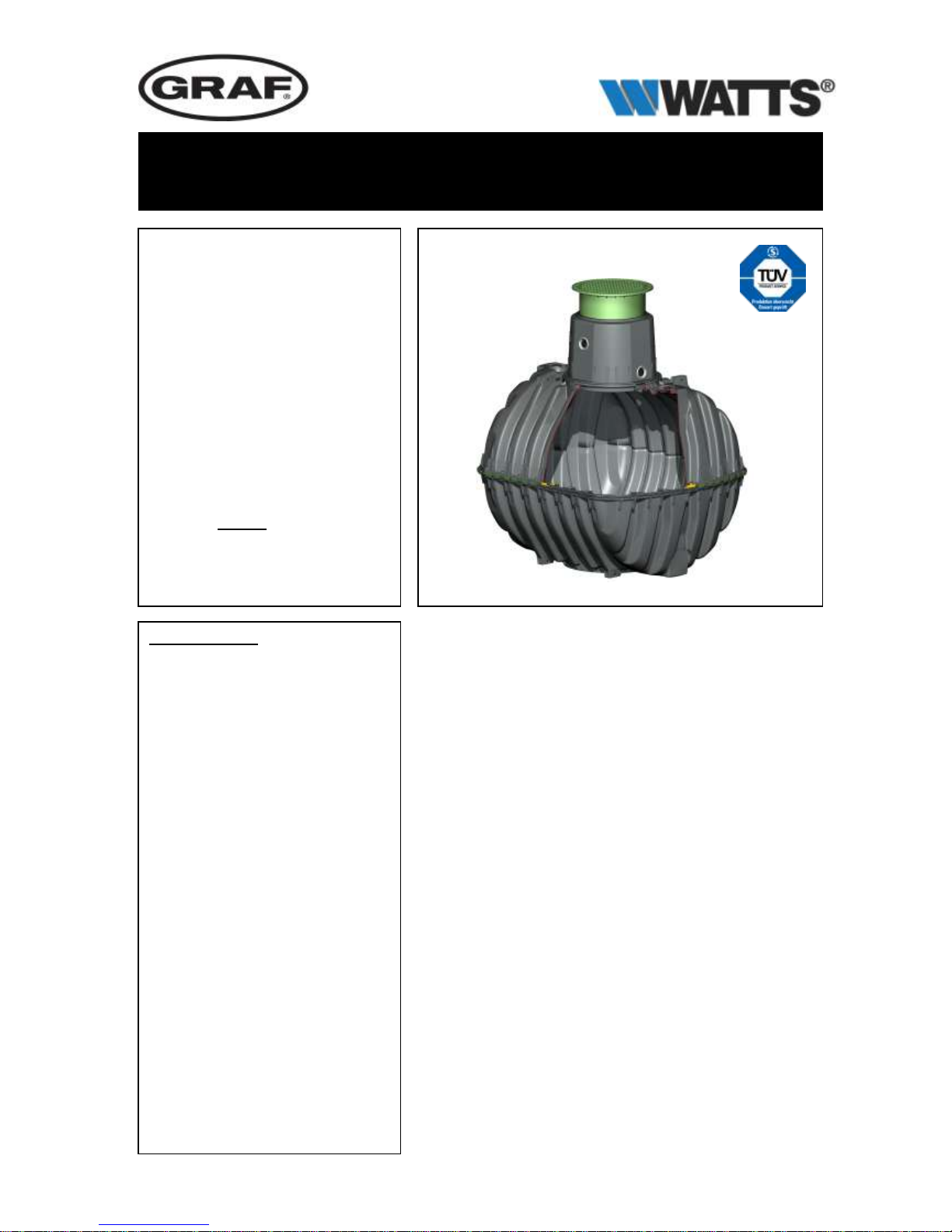
700 gallons / 2700 litres
Order No. 81011001
1000 gallons / 3750 litres
Order No. 81011002
1250 gallons / 4800 litres
Order No. 81011003
1700 gallons / 6500 litres
Order No. 81010059
Check the tanks for possible
damage before installing them
into the excavation pit.
The installation must be conducted by a qualified company.
Installation and maintenance instructions for Carat - S
series rainwater storage tank
distributed in the U.S. by
Page 2
2 of 13
2. Installation / assembly conditions
WARNING
KEEP THIS INSTRUCTION MANUAL AND MAKE IT AVAILABLE FOR ALL END USERS
Read through these instructions before beginning installation. FAILURE TO
COMPLY WITH THESE INSTRUCTIONS CAN RESULT IN SERIOUS PERSONAL
INJURY OR DEATH AND/OR SEVERE PROPERTY DAMAGE. Watts is not responsible for any damages or injuries that result from improper installation and/or use.
DO NOT USE RAINWATER COLLECTED WITH THIS EQUIPMENT FOR
POTABLE APPLICATIONS SUCH AS DRINKING, SHOWERING, OR
COOKING unless you are using a filtration system specifically designed and
approved for producing potable water from harvested rainwater. Water collected with this system should only be used to water outdoor plantings,
wash vehicles, or use in other outdoor cleaning tasks. Water may be stagnant or contaminated and can cause serious illness and/or death if ingested.
When working on any electrical system and/or system components, the en-
tire system must be disabled by disconnecting it from any and all power
sources to prevent an accidental restart.
Except in the event of work carried out in the tank, the cover of the tank
must always be kept sealed, as any other configuration presents a very high
risk of accident. Only original equipment covers or covers approved in writing by manufacturer may be used.
Separate installation instructions will be shipped with any additional manu-
facturer-approved items you have purchased. Consult those instructions
before making additions to your rainwater collection system.
WARNING
1. Preliminary Considerations
Page 3
3 of 13
Preliminary Considerations
ADDITIONAL WARNINGS
1.1 Safety Issues
All applicable federal, state, and local safety regulations should be observed
during assembly, installation, maintenance, and/or repair of this equipment.
When inspecting tanks, we strongly recommend that a second person be
present.
When inspecting tanks, particularly when standing on them, a 2nd person
must be present.
The installation of the system or any of its individual parts must be con-
ducted by qualified professionals.
The manufacturer offers a comprehensive portfolio of accessories that are
designed to work with each other and can be developed into complete systems. Using unapproved components may cause the system to malfunction,
in which case any existing warranties will not be applicable.
Wear safety glasses and gloves when drilling or cutting during this installa-
tion.
DO NOT ALLOW CHILDREN NEAR THE TANK BEFORE, DURING, OR AFTER
INSTALLATION WITHOUT DIRECT SUPERVISION BY A COMPETENT PERSON.
1.2 Compulsory Labelling
All lines, connections, and outlets of water processed with this equipment must be
labelled with the words “UNTREATED RAINWATER: DO NOT DRINK” in writing or
graphically in order to avoid an accidental connection to the drinking water network even after years of use. Even when there are correct labels, mistakes are
possible if children or other persons unfamiliar with the system are allowed access.
Additionally, all points where water processed by this system is accessible outside
the system must be equipped with child-proof valves.
1.3 State Regulations
The State of Colorado has strict requirements governing the diversion and use of
rainwater. Please check local and state requirements to see if special approval
must be obtained before the installation of this or any other rainwater harvesting
equipment.
1. Preliminary Considerations
Page 4
4 of 13
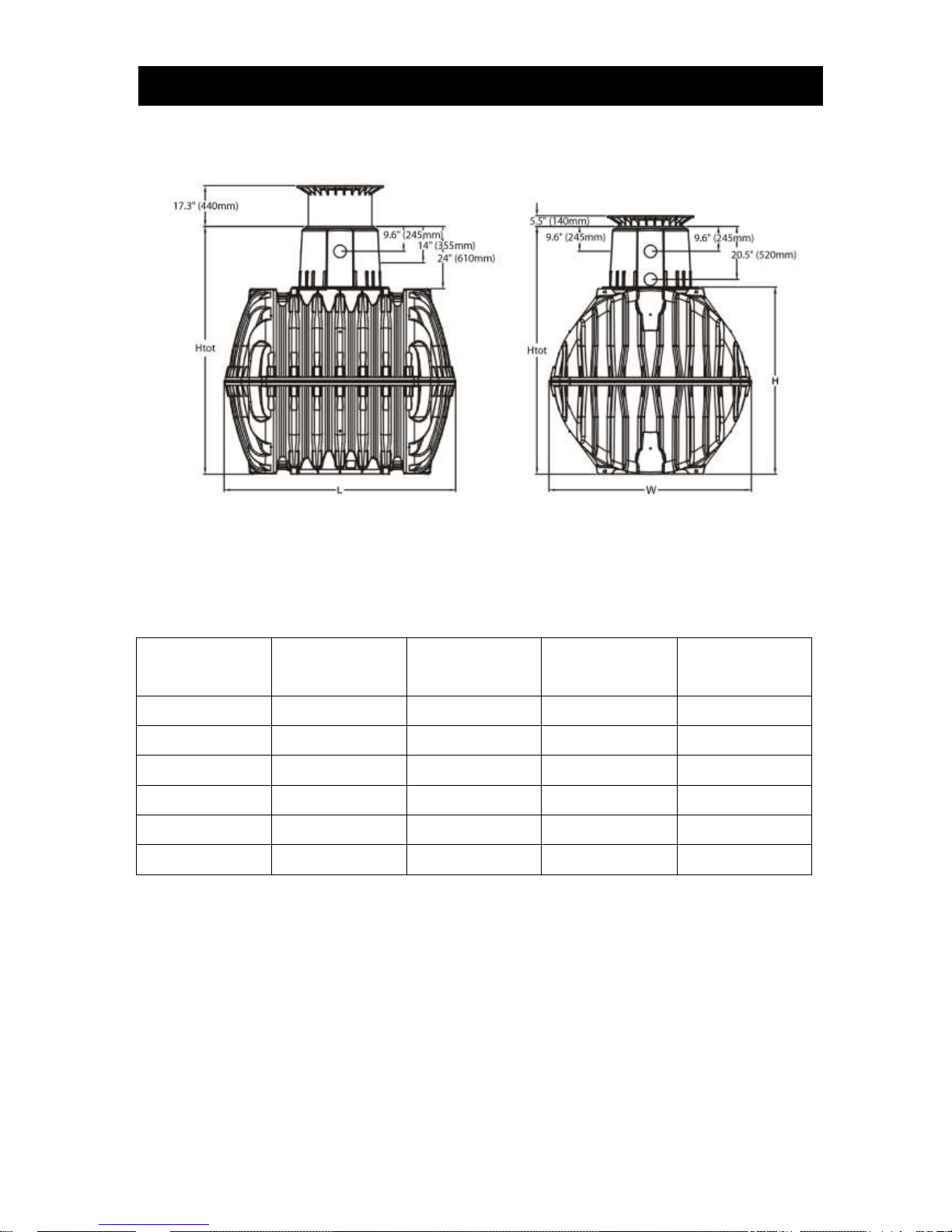
* Htot = total height
Tank
700 US-gallons
2700 litres
1000 US-gallons
3750 litres
1250 US-gallons
4800 litres
1700 US-gallons
6500 litres
Art. No.
81011001
81011002
81011003
81010059
Weight
321.5lbs/120 kg
401.8lbs/150 kg
495.6lbs/185 kg
589.4lbs/220 kg
L
81.9“/2080 mm
89.8“/2280 mm
89.8“/2280 mm
94“/2390 mm
W
61.6“/1565 mm
69“/1755 mm
78.1“/1985 mm
86“/2190 mm
H
55.1“/1400 mm
62.6“/1590 mm
71.7“/1820 mm
82.7“/2100 mm
Htot*
79.1“/2010 mm
86.6“/2200 mm
95.7“/2430 mm
106.7“/2710 mm
2. Technical data
47.2“
Page 5

5 of 13
3. Tank Structure
Cover
Telescopic dome shaft
(can be inclined by 5°)
Profile seal
Tank dome (can be
rotated by 360°)
Tank - tank dome seal
Upper half shell (open)
Centering pins
Circumferential seal
Quick connector
Lower half shell
(closed)
Page 6

6 of 13
4. Assembly
4.1 Tank assembly
First insert the circumferential profile seal into the
sealing groove in the lower half shell . Lightly coat
the entire seal with the enclosed soft soap.
Then insert the centering pins into the
corresponding slots around the circumference.
The upper half shell should now be positioned onto the lower half shell . Make sure that the seal
doesn’t slip out of the groove.
To install the quick connectors , attach them in an
alternating manner to the left and to the right (counterclockwise and clockwise). For this, every second
connector should be adjusted by hand initially, and then
driven securely into place using a hammer and a block
of wood. If attaching the clips is problematic, try
lubricating the inner edges of the connectors and/or
using 3 – 4 C-clamps positioned evenly around the lip
of the tank during the installation. Ensure the
connectors are engaged in their final position. After
completing the installation of the first half of the
connectors, repeat the procedure for the remainder
Page 7

7 of 13
5. Assembling the tank dome and telescopic dome shaft
5.1 Assembling the tank dome
Prior to actual assembly, the enclosed seal is inserted into the tank dome’s sealing groove “A.” After
aligning the openings of the dome with the pipes, lock the dome onto the tank as demonstrated in the
illustration on the right, making sure that the upper seal remains seated during the operation.
NOTE: Once the dome is locked onto the tank it can no longer be rotated.
5.2 Assembling the telescopic dome shaft
The telescopic dome shaft enables adjustment of the tank to
site surfaces with a deviation from level ≤ 5°. The Mini
telescopic dome shaft extends earth coverage between
29.5″/750 mm and 37.4″/950 mm, and the Maxi telescopic
dome shaft extends 29.5″/750 mm and 41.3″/1050 mm.
For assembly purposes, the enclosed profile seal (EPDM) is
inserted into the tank dome's upper sealing groove and is
coated generously with soft soap (do not use mineral oil-based
lubricants, as these attack the seal). The telescopic dome is
then greased, inserted and aligned with the surface of the site.
5.3 Assembling the adapter
For larger coverage heights, an adapter is needed. Install the
adapter between the tank dome and the telescopic dome shaft
making sure that all seals are lubricated with the soft soap.
With the use if the adapter, the maximum earth coverage
should be ≤ 47.2″/1.2 meter from the top of the dome shaft to
the top of the tank.
(in each case in connection with the Maxi telescopic dome
shaft)
A
Telescopic dome shaft (can be inclined by 5°)
Adapter
Tank dome (can be rotated by 360°)
Page 8

8 of 13
6. Installation
6. Installation
6. Installation
6.1 Construction site
When determining where to install the tank, the following should be clarified prior to installation:
- The structural suitability of the ground for this purpose
- minimum depth of water table/maximum groundwater levels and porosity/drainage capability of
the subsoil
- types of load which will occur above the tank location
In order to determine the soil composition and suitability for the project, local building codes and
governing agencies should be consulted.
Page 9

9 of 13
6. Installation
Pedestrian load-bearing dome shaft can handle weights of up to 330 lbs/150 kg for short
periods, and 110 lbs/50 kg for extended periods of time.
Vehicle load-bearing dome shafts are designed to bear
a maximum axle load of 4850 lbs.
Coverage heights with telescopic dome shaft in
green areas (areas where there is pedestrian
traffic only)
Maximum coverage heights with intermediate
section and telescopic dome shaft (in green
areas [pedestrian] only), insertion above watertable.
Coverage heights with cast iron telescopic dome
shaft (class B) in areas used by passenger cars
(insertion above water-table).
The Carat – S series tanks must not be installed
below areas used by vehicles that are heavier
than passenger cars.
Coverage heights on installation/insertion into
water-table – the hatched area specifies the
permissible immersion depth
(areas of pedestrian traffic only).
Page 10

10 of 13
6. Installation
6.2 Trench
To ensure that sufficient space is available for working, the base area of the trench must exceed the
dimensions of the tank by 20”/500 mm on each side; the distance from nearby foundations or any
other built structure must be at least 40”/1000 mm.
The trench embankment must be designed so that slippage or collapse of the embankment wall is
prevented. The foundation soil has to be level and must guarantee sufficient load-bearing capability.
The depth of the trench must be dimensioned so that the max. earth coverage (see section 2 – installation conditions) above the tank is not exceeded. In order to be able to use the system year-round,
the tank and those parts of the system that conduct water must be installed in the frost-free zone of
the soil profile. Normally, the frost-free depth is between 24” – 32”(60-80 cm), but you should obtain
the information that is specific to your area from local agencies.
A 6” – 8” (15-20 cm) layer of compacted, pea gravel (grain size 8/16) should be used as a foundation.
If the soil has inadequate load-bearing capabilities, a
reinforced concrete slab (approx. 4” thick) should be
poured to ensure stability.
6.2.1 Slope, embankment, etc.
On installation of the tank in the immediate vicinity (< 16 ft/5
m) of a hillside, mound or slope, a statically calculated
supporting wall has to be constructed in order to accept the
soil pressure. The wall must exceed the dimensions of the
tank by at least 20”/500 mm in all directions, and must be
located at least 40”/1000 mm away from the tank.
6.2.2 Groundwater and cohesive (waterimpermeable) soils (e.g. clay soil)
If it is anticipated that the tanks will be immersed
deeper into the groundwater than is shown in the
adjacent figure, additional provisions should be made to
guarantee sufficient drainage (See table for max.
immersion depth).
Installation of a drainage pipe is recommended in the
case of cohesive, water-impermeable soils.
6.2.3 Installation adjacent to surfaces used by
vehicles
If the underground tanks are installed adjacent to
surfaces that are used by vehicles heavier than
passenger cars, the minimum distance away from these
surfaces is at least the depth of the trench.
Tank size
700 US-gallons
2700 L
1000 US-gallons
3750 L
1250 US-gallons
4800 L
1700 US-gallons
6500 L
Immersion depth
27.5“/700 mm
31.3“/795 mm
35.8 ″/910 mm
41.3 ″ /1050 mm
Page 11

11 of 13
6. Installation
≥24
6.2.4 Connection of several tanks
Two or more tanks may be connected via the
designated areas near the bottom of the tanks by
means of manufacturer’s special seals and (customer
furnished) basic drainage pipes. The apertures must
be drilled using the manufacturer’s special crown bit in
the appropriate size. The distance between the tanks
should not be less than 24”/600 mm and the pipe must
extend at least 8”/200 mm into the tanks.
6.3 Insertion and filling
Lower the tank (or tanks) carefully into the
prepared trench. If the tank is inserted into
the water-table, fill it 1/3 full with water
before starting to fill in around it. If the tank
is entirely aboved the water-table, this step
may be omitted, however, partially filling
the tank prior to back-filling is highly
recommended.
Fill in the pit around the tank using pea
gravel (maximum grain size 8/16) in 1 ft (30
cm) increments until reaching about 6″
(15cm) over the top of the tank. At that
point you may switch to soil and finish filling
the trench. Individual layers must be well
compacted by hand; mechanical
compaction machines must not be used
under any circumstances.
6.4 Telescopic dome shaft (pedestrian)
Pedestrian load-bearing dome shaft can handle weights of up to 330
lbs/150 kg for short periods, and 110 lbs/50 kg for extended periods
of time.
Important: To prevent loads from being transferred onto the tank,
pea gravel (max. grain size 8/16) is filled in in layers around
the telescope and is evenly compacted. Damage to the tank
dome and telescope must be avoided during this step. The
cover is then positioned and closed to prevent entry by children.
Tighten the threaded connection on the cover tightly to
prevent unauthorized access.
6.5 Telescopic dome shaft (passenger vehicle load
bearing)
Vehicle load-bearing dome shafts are designed to bear a maximum
axle load of 4850 lbs.
If the tank is installed under areas used by passenger cars, the
collar area of the telescope (black) must be supported with
concrete (load class B25 = 0.356 psi/250 kg/m²). The layer of
concrete to be installed must be at least 12″/300 mm wide and
approx. 8″/200 mm high all around. The minimum coverage above
the shoulder of the tank is at least 31.5″/800 mm (max.
41.3″/1050 mm with telescope, coverage up to max. 47.2″/1200
mm possible with intermediate section).
Attention: Use the cast iron cover in all circumstances.
20″
Page 12

IS_WQP_CARAT_09222
©Watts 2009
 Loading...