

Grady-White Journey 258, Chase 273, Advance 257, Fisherman 222, Tournament 225 User Manual
...
TABLE OF CONTENTS
T ABLE OF C ONTENTS
WELCOME ABOARD!
T
ABLE OF CONTENTS
CHAPTER 1: CONSUMER INFORMATION
Owner’s Packet. . . . . . . . . . . . . . . . . . . . . . . . . . . . . . . . . . . . . . . . 1–1
Warranty Information . . . . . . . . . . . . . . . . . . . . . . . . . . . . . . . . . . . 1–1
Dealer’s Responsibilities. . . . . . . . . . . . . . . . . . . . . . . . . . . . . . . . . 1–1
Consumer Responsibilities . . . . . . . . . . . . . . . . . . . . . . . . . . . . . . . 1–2
Hazard Warning Labels . . . . . . . . . . . . . . . . . . . . . . . . . . . . . . . . . . 1–3
CHAPTER 2: SAFETY
Required Safety Equipment . . . . . . . . . . . . . . . . . . . . . . . . . . . . . . . 2–1
Additional Recommended Equipment . . . . . . . . . . . . . . . . . . . . . . . 2–1
Registration Numbers . . . . . . . . . . . . . . . . . . . . . . . . . . . . . . . . . . . 2–1
Emergency Stop Switch . . . . . . . . . . . . . . . . . . . . . . . . . . . . . . . . . . 2–2
Emergency Information. . . . . . . . . . . . . . . . . . . . . . . . . . . . . . . . . . 2–2
Boating Safety Tips . . . . . . . . . . . . . . . . . . . . . . . . . . . . . . . . . . . . 2–3
Certification . . . . . . . . . . . . . . . . . . . . . . . . . . . . . . . . . . . . . . . . . . 2–4
Loading Capacity . . . . . . . . . . . . . . . . . . . . . . . . . . . . . . . . . . . . . . 2–4
Carbon Monoxide . . . . . . . . . . . . . . . . . . . . . . . . . . . . . . . . . . . . . . 2–5
Suggested Boating Classes And Reading Material . . . . . . . . . . . . . . 2–6
CHAPTER 3: GENERAL INFORMATION
Fueling . . . . . . . . . . . . . . . . . . . . . . . . . . . . . . . . . . . . . . . . . . . . . . 3–1
Fuel System . . . . . . . . . . . . . . . . . . . . . . . . . . . . . . . . . . . . . . . . . . 3–2
Fuel Select Valve . . . . . . . . . . . . . . . . . . . . . . . . . . . . . . . . . . . . . . 3–3
Pollution Regulations . . . . . . . . . . . . . . . . . . . . . . . . . . . . . . . . . . . 3–3
Discharge of Oil or Hazardous Substances . . . . . . . . . . . . . . . . . . . . . . . . . . . . . . . . . . . . . 3–4
Disposal of Plastics or Garbage . . . . . . . . . . . . . . . . . . . . . . . . . . . . . . . . . . . . . . . . . . . . . . 3–4
Trailering . . . . . . . . . . . . . . . . . . . . . . . . . . . . . . . . . . . . . . . . . . . . 3–4
Predeparture . . . . . . . . . . . . . . . . . . . . . . . . . . . . . . . . . . . . . . . . . . 3–5
Casting Off & Approaching The Dock . . . . . . . . . . . . . . . . . . . . . . . 3–5
Anchoring . . . . . . . . . . . . . . . . . . . . . . . . . . . . . . . . . . . . . . . . . . . . 3–5
Towing . . . . . . . . . . . . . . . . . . . . . . . . . . . . . . . . . . . . . . . . . . . . . . 3–6
Shallow Water . . . . . . . . . . . . . . . . . . . . . . . . . . . . . . . . . . . . . . . . 3–6
Windlass . . . . . . . . . . . . . . . . . . . . . . . . . . . . . . . . . . . . . . . . . . . . . 3–7
General Information On Boat Handling . . . . . . . . . . . . . . . . . . . . . . 3–7
Twin Engine Boats . . . . . . . . . . . . . . . . . . . . . . . . . . . . . . . . . . . . . 3–7
Commonly Used Nautical Terms . . . . . . . . . . . . . . . . . . . . . . . . . . . 3–8
CHAPTER 4: PERFORMANCE
Performance Factors . . . . . . . . . . . . . . . . . . . . . . . . . . . . . . . . . . . . 4–1
Engine Efficiency. . . . . . . . . . . . . . . . . . . . . . . . . . . . . . . . . . . . . . . . . . . . . . . . . . . . . . . . . 4–1
Weather Conditions . . . . . . . . . . . . . . . . . . . . . . . . . . . . . . . . . . . . . . . . . . . . . . . . . . . . . . . 4–1
Load Distribution . . . . . . . . . . . . . . . . . . . . . . . . . . . . . . . . . . . . . . . . . . . . . . . . . . . . . . . . . 4–1
Marine Growth . . . . . . . . . . . . . . . . . . . . . . . . . . . . . . . . . . . . . . . . . . . . . . . . . . . . . . . . . . . 4–1
Trim . . . . . . . . . . . . . . . . . . . . . . . . . . . . . . . . . . . . . . . . . . . . . . . . . . . . . . . . . . . . . . . . . . . 4–1
Propeller . . . . . . . . . . . . . . . . . . . . . . . . . . . . . . . . . . . . . . . . . . . . . . . . . . . . . . . . . . . . . . . . 4–2
Propulsion System – Outboard . . . . . . . . . . . . . . . . . . . . . . . . . . . . . 4–3

T ABLE OF CONTENTS
Engine Warranty . . . . . . . . . . . . . . . . . . . . . . . . . . . . . . . . . . . . . . . 4–3
Steering . . . . . . . . . . . . . . . . . . . . . . . . . . . . . . . . . . . . . . . . . . . . . 4–4
Throttle/Shift Control . . . . . . . . . . . . . . . . . . . . . . . . . . . . . . . . . . 4–5
CHAPTER 5: INSTRUMENTATION AND SWITCHES
Yamaha Instrumentation Panel . . . . . . . . . . . . . . . . . . 5–1
Digital Speedometer and Fuel Management . . . . . . . . . . . . . . . . . . . 5–1
Digital Tachometer . . . . . . . . . . . . . . . . . . . . . . . . . . . . . . . . . . . . . 5–2
Switch Panel . . . . . . . . . . . . . . . . . . . . . . . . . . . . . . . 5–3
CHAPTER 6: MAINTENANCE AND SERVICE
General . . . . . . . . . . . . . . . . . . . . . . . . . . . . . . . . . . . . . . . . . . . . . . 6–1
Exterior Fiberglass Finish . . . . . . . . . . . . . . . . . . . . . . . . . . . . . . . . 6–1
Maintenance . . . . . . . . . . . . . . . . . . . . . . . . . . . . . . . . . . . . . . . . . . . . . . . . . . . . . . . . . . . . . 6–1
Cleaning . . . . . . . . . . . . . . . . . . . . . . . . . . . . . . . . . . . . . . . . . . . . . . . . . . . . . . . . . . . . . . . . 6–1
Finish/Waxing . . . . . . . . . . . . . . . . . . . . . . . . . . . . . . . . . . . . . . . . . . . . . . . . . . . . . . . . . . . 6–2
Repairing . . . . . . . . . . . . . . . . . . . . . . . . . . . . . . . . . . . . . . . . . . . . . . . . . . . . . . . . . . . . . . . 6–3
Bottom Paint . . . . . . . . . . . . . . . . . . . . . . . . . . . . . . . . . . . . . . . . . . 6–3
Canvas . . . . . . . . . . . . . . . . . . . . . . . . . . . . . . . . . . . . . . . . . . . . . . 6–3
Maintenance . . . . . . . . . . . . . . . . . . . . . . . . . . . . . . . . . . . . . . . . . . . . . . . . . . . . . . . . . . . . . 6–3
Snaps And Zippers . . . . . . . . . . . . . . . . . . . . . . . . . . . . . . . . . . . . . . . . . . . . . . . . . . . . . . . . 6–4
Vinyl. . . . . . . . . . . . . . . . . . . . . . . . . . . . . . . . . . . . . . . . . . . . . . . . . . . . . . . . . . . . . . . . . . . 6–4
Storage . . . . . . . . . . . . . . . . . . . . . . . . . . . . . . . . . . . . . . . . . . . . . . . . . . . . . . . . . . . . . . . . . 6–4
Upholstery . . . . . . . . . . . . . . . . . . . . . . . . . . . . . . . . . . . . . . . . . . . 6–5
Duratrim/Polyethylene/Plexiglass/Vinyl . . . . . . . . . . . . . . . . . . . . . 6–5
Scuppers. . . . . . . . . . . . . . . . . . . . . . . . . . . . . . . . . . . . . . . . . . . . . 6–5
Caulking/Gasket . . . . . . . . . . . . . . . . . . . . . . . . . . . . . . . . . . . . . . . 6–5
Hardware/Hardtop Frame/Stainless Steel Rails . . . . . . . . . . . . . . . . . 6–5
Hardware Mounting . . . . . . . . . . . . . . . . . . . . . . . . . . . . . . . . . . . . 6–6
Maintenance Procedure For Anodized Aluminum Components . . . . . 6–6
Fuel System Maintenance . . . . . . . . . . . . . . . . . . . . . . . . . . . . . . . . 6–6
Fuel Tank Compartment . . . . . . . . . . . . . . . . . . . . . . . . . . . . . . . . . 6–7
Shower Sump . . . . . . . . . . . . . . . . . . . . . . . . . . . . . . . . . . . . . . . . . 6–7
Batteries . . . . . . . . . . . . . . . . . . . . . . . . . . . . . . . . . . . . . . . . . . . . . 6–7
Light Bulb Replacement Guide . . . . . . . . . . . . . . . . . . . . . . . . . . . . 6–9
Accessory Wiring Color – Fuse/Breaker Sizes . . . . . . . . . . . . . . . . 6–10
CHAPTER 7: WINTERIZATION AND STORAGE
General . . . . . . . . . . . . . . . . . . . . . . . . . . . . . . . . . . . . . . . . . . . . . . 7–1
Boat Storage . . . . . . . . . . . . . . . . . . . . . . . . . . . . . . . . . . . . . . . . . . 7–1
Cleaning And Lubricating The Boat . . . . . . . . . . . . . . . . . . . . . . . . . 7–2
Draining & Water System . . . . . . . . . . . . . . . . . . . . . . . . . . . . . . . . 7–2
Head System. . . . . . . . . . . . . . . . . . . . . . . . . . . . . . . . . . . . . . . . . . 7–2
Batteries . . . . . . . . . . . . . . . . . . . . . . . . . . . . . . . . . . . . . . . . . . . . . 7–3
Engines . . . . . . . . . . . . . . . . . . . . . . . . . . . . . . . . . . . . . . . . . . . . . 7–3
Fuel System . . . . . . . . . . . . . . . . . . . . . . . . . . . . . . . . . . . . . . . . . . 7–3
Storage Checklist . . . . . . . . . . . . . . . . . . . . . . . . . . . . . . . . . . . . . . 7–3
Getting Boat Out After Storage . . . . . . . . . . . . . . . . . . . . . . . . . . . . 7–4
Prior To Launching . . . . . . . . . . . . . . . . . . . . . . . . . . . . . . . . . . . . . 7–4
After Launching . . . . . . . . . . . . . . . . . . . . . . . . . . . . . . . . . . . . . . . 7–4

T ABLE OF C ONTENTS
CHAPTER 8: 306 BIMINI
Specifications . . . . . . . . . . . . . . . . . . . . . . . . . . . . . . 8–1
Optional Features . . . . . . . . . . . . . . . . . . . . . . . . . . . 8–1
Accessories . . . . . . . . . . . . . . . . . . . . . . . . . . . . . . . . . . . . . . . . . . . 8–1
Canvas Options. . . . . . . . . . . . . . . . . . . . . . . . . . . . . . . . . . . . . . . . 8–1
Operation Of Standard Features . . . . . . . . . . . . . . . . . . 8–2
Switch Panel. . . . . . . . . . . . . . . . . . . . . . . . . . . . . . . . . . . . . . . . . . 8–2
Auxiliary Fuse Panel. . . . . . . . . . . . . . . . . . . . . . . . . . . . . . . . . . . . 8–3
Main Circuit Breaker . . . . . . . . . . . . . . . . . . . . . . . . . . . . . . . . . . . 8–4
Accessory Outlet - 12 Volt . . . . . . . . . . . . . . . . . . . . . . . . . . . . . . . 8–4
Compass. . . . . . . . . . . . . . . . . . . . . . . . . . . . . . . . . . . . . . . . . . . . . 8–4
Aft Rigging Compartment . . . . . . . . . . . . . . . . . . . . . . . . . . . . . . . . 8–4
Bilge Pump With Float Switch . . . . . . . . . . . . . . . . . . . . . . . . . . . . . 8–4
Bilge Pump Location . . . . . . . . . . . . . . . . . . . . . . . . . . . . . . . . . . . . 8–4
Shower Sump Pump . . . . . . . . . . . . . . . . . . . . . . . . . . . . . . . . . . . . 8–5
Cockpit Shower . . . . . . . . . . . . . . . . . . . . . . . . . . . . . . . . . . . . . . . 8–5
Console Fresh Water . . . . . . . . . . . . . . . . . . . . . . . . . . . . . . . . . . . . 8–5
Leanbar Fresh Water . . . . . . . . . . . . . . . . . . . . . . . . . . . . . . . . . . . . 8–5
Windshield Washer Switch . . . . . . . . . . . . . . . . . . . . . . . . . . . . . . . 8–5
Transducer Flats . . . . . . . . . . . . . . . . . . . . . . . . . . . . . . . . . . . . . . . 8–5
Seacocks . . . . . . . . . . . . . . . . . . . . . . . . . . . . . . . . . . . . . . . . . . . . . 8–6
Livewell - Raw Water . . . . . . . . . . . . . . . . . . . . . . . . . . . . . . . . . . . 8–6
Washdown Operation . . . . . . . . . . . . . . . . . . . . . . . . . . . . . . . . . . . 8–7
Battery Select Switches. . . . . . . . . . . . . . . . . . . . . . . . . . . . . . . . . . 8–7
Trim Tabs. . . . . . . . . . . . . . . . . . . . . . . . . . . . . . . . . . . . . . . . . . . . 8–8
Head Operating Instructions . . . . . . . . . . . . . . . . . . . . . . . . . . . . . . 8–9
Marine Head (W/ Hand Pump) Operation . . . . . . . . . . . . . . . . . . . . . . . . . . . . . . . . . . . . . . 8–9
Electric Marine Head Operation. . . . . . . . . . . . . . . . . . . . . . . . . . . . . . . . . . . . . . . . . . . . . . 8–9
Emptying Marine Head Holding Tank By Overboar d D ischarge . . . . . . . . . . . . . . . . . . . . 8–9
Emptying Marine Head Holding Tank Through Deck Pump-out . . . . . . . . . . . . . . . . . . . . 8–9
Operation Of Optional Features . . . . . . . . . . . . . . . . . 8–10
Bow Thruster . . . . . . . . . . . . . . . . . . . . . . . . . . . . . . . . . . . . . . . . 8–10
Dockside Power . . . . . . . . . . . . . . . . . . . . . . . . . . . . . . . . . . . . . . 8–10
Connecting The Dockside Power. . . . . . . . . . . . . . . . . . . . . . . . . . . . . . . . . . . . . . . . . . . . 8–10
Disconnecting The Dockside Power . . . . . . . . . . . . . . . . . . . . . . . . . . . . . . . . . . . . . . . . . 8–10
Battery Charger (Dockside Power Option) . . . . . . . . . . . . . . . . . . . . . . . . . . . . . . . . . . . . 8–11
T-top . . . . . . . . . . . . . . . . . . . . . . . . . . . . . . . . . . . . . . . . . . . . . . 8–11
Outriggers . . . . . . . . . . . . . . . . . . . . . . . . . . . . . . . . . . . . . . . . . . 8–11
Power Assist Hydraulic Steering . . . . . . . . . . . . . . . . . . . . . . . . . . 8–12
Stereo. . . . . . . . . . . . . . . . . . . . . . . . . . . . . . . . . . . . . . . . . . . . . . 8–12
Sirius Satellite Radio . . . . . . . . . . . . . . . . . . . . . . . . . . . . . . . . . . 8–12
In for mat ion al D raw ings . . . . . . . . . . . . . . . . . . . . . . 8–13
Access Plate And Rigging Tube Location. . . . . . . . . . . . . . . . . . . . 8–13
Labels And Location . . . . . . . . . . . . . . . . . . . . . . . . . . . . . . . . . . . 8–14
Fuel System . . . . . . . . . . . . . . . . . . . . . . . . . . . . . . . . . . . . . . . . . 8–15
Livewell/Washdown System Layout . . . . . . . . . . . . . . . . . . . . . . . 8–16
Livewell/Washdown System . . . . . . . . . . . . . . . . . . . . . . . . . . . . . 8–17
Freshwater System . . . . . . . . . . . . . . . . . . . . . . . . . . . . . . . . . . . . 8–18
Marine Head Layout . . . . . . . . . . . . . . . . . . . . . . . . . . . . . . . . . . . 8–19
Thru Hull Detail . . . . . . . . . . . . . . . . . . . . . . . . . . . . . . . . . . . . . . 8–20
Accessory Wiring . . . . . . . . . . . . . . . . . . . . . . . . . . . . . . . . . . . . . 8–21

T ABLE OF CONTENTS
Upper & Lower Console Wiring . . . . . . . . . . . . . . . . . . . . . . . . . . 8–22
Battery Wiring With Select Switches . . . . . . . . . . . . . . . . . . . . . . . 8–23
Hard Top Layout and Wiring. . . . . . . . . . . . . . . . . . . . . . . . . . . . . 8–24
Stereo Layout and Wiring with Factory T-top . . . . . . . . . . . . . . . . 8–25
Stereo Layout and Wiring without Factory T-top . . . . . . . . . . . . . . 8–26
Typical Outboard Switch Panel Wiring . . . . . . . . . . . . . . . . . . . . . 8–27
Dockside Power . . . . . . . . . . . . . . . . . . . . . . . . . . . . . . . . . . . . . . 8–28
CHAPTER 9: LIMITED WARRANTY
Registration Of Purchase: . . . . . . . . . . . . . . . . . . . . . . . . . . . . . . . . 9–1
Five Year Hull Transferable Warranty . . . . . . . . . . . . . . . . . . . . . . . 9–1
One Year Material And Workmanship Warranty . . . . . . . . . . . . . . . . 9–1
Warranty Claim Procedures. . . . . . . . . . . . . . . . . . . . . . . . . . . . . . . 9–2
TRANSFERABLE WARRANTY FORM

WELCOME
Chapter 1: Consumer Information
OWNER’S PACKET
Your Grady-White has many features and accessories that have existing printed material
provided by the various equipment manufacturers. This information is compiled in a package that
we will reference throughout this manual as an “Owner’s Packet.” This Owner’s Packet includes a
Grady-White Owner’s Manual and Engine Manual(s) to advise on operation, service,
specifications, maintenance, warranty, and other useful facts. While reading your Grady-White
manual, you will find other technical literature referenced as resources for detailed information.
The Owner’s Packet will also consist of operation guides, informative labels, and product
warranties you will need to be acquainted with. Your Owner ’s Packet can also be used to retain
instructions and data compiled on additional equipment and accessories installed after delivery.
Sportfish, Cruisers, Yachts Owner’s Manual, a book published by the National Marine
Manufacturer’s Association (NMMA), has been included with your Owner’s Packet as a
supplement. This publication will be referenced in your Grady-White Owner’s Manual to present
additional instructions and information on basic boating.
WARRANTY INFORMATION
The Grady-White warranty is located on the next to last page of this manual. Upon the
purchase of your new Grady-White Boat, the dealer will fill out a warranty card. This card
will be kept on file at the dealership and at the Grady-White factory. A copy will be provided for
your records and should be kept with other valuable documents for future reference. For questions
regarding your warranty please contact your dealership.
DEALER’S RESPONSIBILITIES
Throughout the fabricating and assembly processes, your Grady-White has undergone a series
of strict inspections. Subsequent to the final factory overview, your dealer must perform
additional pre-delivery checks and approve your Grady-White for delivery.
DEALER RESPONSIBILITIES INCLUDE PROVIDING THE FOLLOWING:
• An orientation of the general operation of your Grady-White.
• A warranty card to be completed and signed by the dealer and the customer. This warranty card
is to be sent to Grady-White Boats to validate the warranty.
• An explanation of safety issues regarding the use of containment systems and components.
• A complete Owner’s Packet containing literature and information regarding your Grady-White
and its separate warranted products’ operation, installation, and maintenance instructions.
• A review of all warranties pointing out the importance of mailing warranty and registration to
various manufacturers within the required time limits.
• Guidance on acquiring local and out of area service during and out of warranty periods.
1–1
W ELCOME
CONSUMER RESPONSIBILITIES
THE FOLLOWING ARE RESPONSIBILITIES OF THE GRADY-WHITE OWNER:
• Read and understand the express limited warranty.
• Study in detail all literature and instructions enclosed, and use all equipment in accordance.
• Examine the boat and confirm all systems are working suitably at the time of accepting
delivery.
• Render proper maintenance and periodic servicing of the boat in accordance with suggestions
in the Owner’s Manual.
• Return the boat to the selling dealer for an engine inspection. Refer to the engine’s owner ’s
manual for the proper maintenance schedule.
Grady-White Boats has a permanent record of your boat which is retained under its “Hull
Identification Number” (HIN). Data regarding equipment and accessories, as well as dealer/
shipping information is documented. When contacting your dealer concerning warranties or
service, please have all relevant information such as serial numbers (HIN) and model number
available. This information is on your copy of the warranty card.
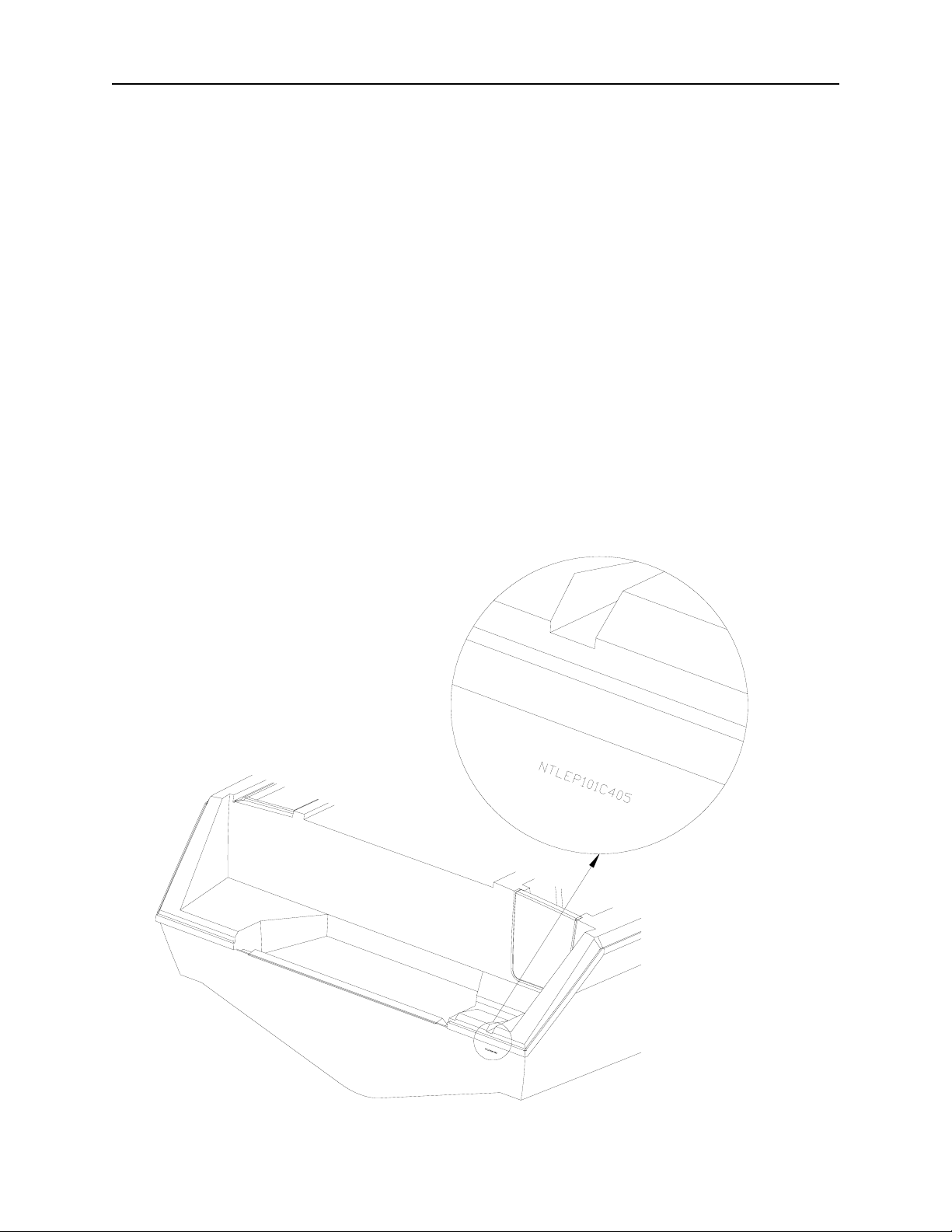
The “Hull Identification Number,” located on the starboard side of the transom, is a
significant source of identification and must be noted in all correspondence and orders. Failure to
include the HIN only creates delay.
1–2
WELCOME
HAZARD WARNING LABELS
The hazard warning labels shown below are applied throughout this manual to alert the
customer of potentially dangerous situations that can lead to death, personal injury, and/or product
damage. We urge you to observe these warnings and comply with all safety recommendations.
D A N G E R
!
This symbol alerts you to imminently hazardous situations which will cause severe personal injury
or death if the warning is ignored.
W A R N I N G
!
This symbol alerts you to potentially hazardous situations or unsafe practices that could resul t in
severe personal injury or death if the warning is ignored.
C A U T I O N
!
This symbol alerts you to potentially hazardous situations that may result in minor personal
injury or cause product or property damage if the warning is ignored.
N O T I C E
This symbol calls attention to installation, operation, or maintenance information which is
important for proper operation, but is not hazard related.
1–3

W ELCOME
1–4

SAFETY
Chapter 2: Safety
REQUIRED SAFETY EQUIPMENT
The US Coast Guard (USCG) requires that every boat have specific equipment on board.
Check with local regulations on mandatory equipment apart from the list of Coast Guard
requirements. See Sportfish, Cruisers, Yachts Owner’s Manual, page 17, for details on the
following required safety equipment.
•Fire Extinguisher
Boats should be equipped with a marine approved fire extinguisher.
• Personal Flotation
All passengers must have an USCG approved personal flotation device (PFD).
Children and non-swimmers are advised to wear a PFD at all times.
• Sound Signaling Device (Horn, Bell Or Whistle)
Your Grady-White is equipped with a horn that meets USCG requirements.
• Visual Distress Signals
USCG approved visual distress signals are required on U. S. waters. See page 33 of the
pamphlet Sportfish, Cruisers, Yachts Owner’s Manual enclosed with this manual for more
information.
• Lighting
Grady-White boats are equipped with navigational lights that meet requirements for
recreational vessels for inland and international waters.
ADDITIONAL RECOMMENDED EQUIPMENT
In addition to the required safety equipment, there are additional items that will provide an
extra margin of safety and convenience for you and your passengers while boating. For an
extended list of basic gear, tools and spare parts, reference page 18 of the pamphlet Sportfish,
Cruisers, Yachts Owner’s Manual enclosed with this manual.
Keep tools and spare parts in good condition. Replace parts removed from spare parts kit.
Most importantly, use US Coast Guard approved or marine certified parts where applicable.
Conditions found requiring corrective action should be worked on by a qualified repairman.
REGISTRATION NUMBERS
Federal and State laws require a powerboat to be registered in the State where it is primarily
used. Registration numbers and validation stickers must be displayed according to regulations.
The registration certificate must be on board when boating. The boat serial number or Hull
Identification Number (HIN, page 1–2) is required on the registration form. The HIN is located
on the upper right hand corner of the transom, and is the most important identifying factor. The
HIN should be included in all documents and correspondence to provide you timely service.
2–1

S AFETY
EMERGENCY STOP SWITCH
All Grady-Whites are equipped with an emergency stop switch. This is a safety feature that if
used properly will shut the engine(s) down if the operator leaves or falls from the helm position.
The ignition shutdown system includes a shut-off switch, switch clip, lanyard and lanyard clip.
The lanyard clip is attached to the operator. If a situation arises where the boat should stop, a pull
on the cord to release the clip from the shut-off switch will shut down the engine(s). To reset the
emergency stop switch, simply reinstall the switch clip. The decision to use the emergency stop
switch rests with the owner/operator. See page 72 in Sportfish, Cruisers, Yachts Owner’s Manual.
EMERGENCY INFORMATION
While boating, unpleasant situations may develop. You should prepare yourself on how to
cope with them whether they happen aboard your vessel or someone else’s. Anticipate and game
plan for specific situations such as fire, man overboard, collision, etc. to give you the confidence
and ability necessary to handle an emergency. The key is to remain calm. For emergency
procedures, see Section 4 in Sportfish, Cruisers, Yachts Owner’s Manual.
• Rendering Assistance
The owner or operator of a vessel is required by law to render all practical or necessary
assistance to any person or vessel affected by collision, accident or casualty. However, you
are not required to endanger your vessel or passengers to render assistance.
• Accident Reporting
Report all boating accidents to your local authorities. Federal regulations require boat
operators involved in an accident to submit a written report within 48 hours. In the event of
death or disappearance, notification is required immediately by phone or radio in addition
to the written report. These reports can be submitted to the State Boating Law Administrator.
Forms can be obtained through the USCG, local harbor patrol offices, sheriff, and police
stations.
• Lightning Precautions
This awareness is included to ensure the safety of the owner and passengers. Always be
mindful of the weather! When a lightning storm advances, certain safety precautions should
be taken. Dock the boat and seek shelter on land. If this is not possible, seek refuge inside the
boat until the storm has passed. Stay out of the water! Lightning will seek a ground when it
strikes and may pass through metal components if it hits your boat. For this reason, avoid
contact with metal parts of the boat under these conditions.
2–2

SAFETY
BOATING SAFETY TIPS
Safety is an important aspect of boating. Your safety as well as the safety of your passengers
and vessel is your responsibility. The following precautions and the ones mentioned in section 1
of Sportfish, Cruisers, Yachts Owner’s Manual will add to you and your passengers’ boating
safety and pleasure.
• Before operating your Grady-White READ AND STUDY ALL OPERATION AND
MAINTENANCE MANUALS. It is important that you fully understand how to use your
boat. Contact your Grady-White dealer for questions. Proper use and service will insure quality
performance and longevity of your boat.
• A written float plan left with a RESPONSIBLE person can serve as valuable information
should you not return as scheduled. Upon returning, your primary responsibility is to notify the
person of your return.
• NEVER operate or allow anyone to operate your boat while under the influence of drugs or
alcohol.
• Individuals under the age of 16 should not be allowed to operate your boat.
Inexperienced drivers should have constant and direct supervision.
• Instruct at least one passenger on the fundamentals of basic boating and safe operation in the
event of an emergency.
• While boating, passengers should be settled in a safe position. Use hand holds and rails for
steadiness. Do not allow bow, transom or gunwale riding. The captain is ultimately responsible
for their passenger’s safety.
• Keep your boat speed under control. Respect for other boaters and those on shore are common
courtesies. The boat’s operator is responsible for injury or damage caused by the boat or the
wake. Your wake could swamp a smaller craft and endanger its passengers. Stay alert for
posted “No Wake Zones”.
• Become familiar with the handling personality and limitations of your boat.
• Never allow swimmers/skiers to enter or exit the boat with engine(s) running. A shift lever
in neutral could become engaged accidentally. Also, exhaust fumes from the outboard
engine(s) contain carbon monoxide gas. These fumes may concentrate in this area. See more
information on “Dangers of Carbon Monoxide” on page 2-5.
• Obtain information and a chart for new areas when possible.
• Clean water and air are responsibilities for all persons. Use litter containers on board and
dispose of refuse properly. See “Pollution Regulations” on page 3–3.
• Know and obey the “Rules of the Road”. See Sportfish, Cruisers, Yachts Owner’s Manual,
beginning on page 19, for a better understanding of right of ways, signals and waterway
markers.
2–3
S AFETY
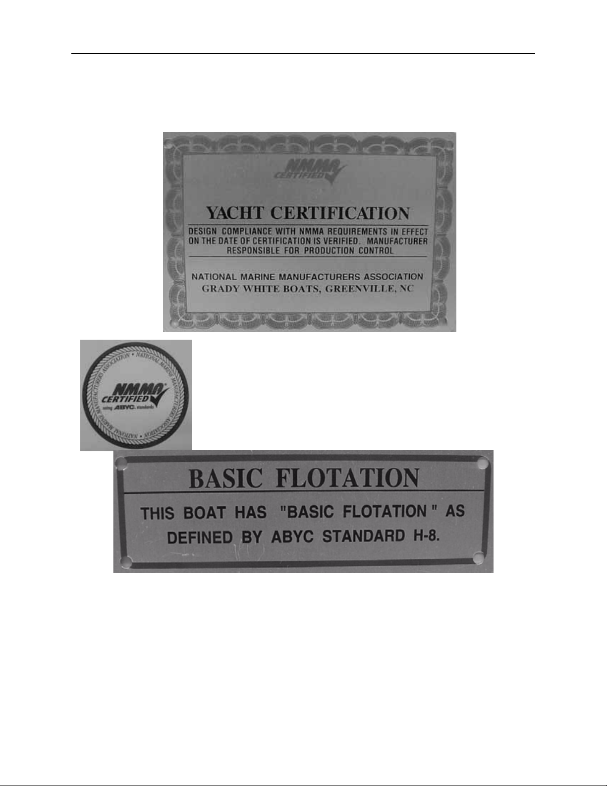
CERTIFICATION
At the helm station you will find a NMMA (National Marine Manufacturers Association)
Yacht Certification tag. This means your yacht complies with the Coast Guard safety standards.
(NOTE: Any boat with an overall length of 26 feet or greater is defined as a “yacht” by NMMA.)
This label means your Grady-White is certified by the NMMA. With
this tag, you are assured your fuel system, electrical system, lighting,
ventilation, and steering are not only in compliance with the US Coast
Guard regulations, but also meet the more stringent standards of the
NMMA. The NMMA is a national trade organization serving all
elements of the recreational boating industry including manufacturers
of boating equipment. With this tag, you can have confidence in the
safety of your boat.
This label means that Grady-White has designed and built your boat to the ABYC standard
H-8, buoyancy in the event of swamping. Basic flotation is defined as having enough foam in the
boat to create buoyancy and prevent sinking under swamped conditions.
LOADING CAPACITY
Though overloading is a primary cause of many boating accidents, improper loading is
equally hazardous. Boaters should know the amount of weight on board and evenly distribute the
weight within the boat.
2–4

SAFETY
CARBON MONOXIDE
W A R N I N G
!
(CO) is produced by all combustion engine(s) and generator sets.
Avoid brain damage or death from carbon monoxide.
Keep cockpit and cabin areas well ventilated.
Avoid blockage of exhaust outlets.
Signs of exposure include headache, nausea, dizziness and drowsiness.
Carbon Monoxide, commonly written (CO), is a colorless, odorless gas emitted from any
boat’ s exhaus t. The gas is s imila r in weight to the air we breathe. Therefore, it cannot be expected
to rise or fall, but will accumulate in confined spaces.
Carbon monoxide is poisonous, and potentially fatal if breathed over an extended period of
time. Symptoms of CO poisoning include dizziness, nausea, headache, sleepiness, vomiting,
throbbing in the temples, muscular twitching, and an inability to think clearly. If you or anyone
else experience these symptoms, immediately get away from fumes and into an area where
plenty of FRESH air can be consumed. If any symptoms from above persist, seek medical
attention.
Carbon monoxide can accumulate in cabins and under canvas. If your boat is equipped
with a canvas that encloses the aft cockpit and propulsion equipment, do not operate the boat with
this canvas closed.
Outboard engine exhaust fumes contain carbon monoxide. These fumes may concentrate at
the motorwell area. Do not board your vessel with the engine(s) running. Also, do not occupy the
motorwell area with the engine(s) running.
Operators need to be aware of the influence of other boats on their vessel as well as the effects
they have on neighboring crafts. Of primary concern is the operation of an auxiliary generator
with boats moored along side each other. This situation creates an atmos phere which is filled with
CO, and extremely dangerous.
W A R N I N G
!
BE AWARE of the significance your exhaust may have on other vessels. Likewise, BE AWARE
that the operation of other vessel's equipment may influence the carbon monoxide concentration
on your vessel.
W A R N I N G
!
Exhaust fumes from engine(s) contain (CO). Boats with canvas deployed are more likely to collect
exhaust fumes. Avoid brain damage or death from (CO). Keep cockpit and cabin areas well
ventilated. Signs of exposure include headache, nausea, dizziness and drowsiness.
2–5

S AFETY
SUGGESTED BOATING CLASSES AND READING MATERIAL
Like a car, boats must be operated according to safety rules and traffic regulations. Although
we include some basic boating tips in this manual, a thorough review of the safety rules and
regulations for boating is beyond the scope of this text.
We support the work of the United States Coast Guard Auxiliary and the United States Power
Squadrons. We urge you to attend any instructional classes sponsored by these organizations.
Reference page 8 of Sportfish, Cruisers, Yachts Owner’s Manual for training options, and page 23
for information on charts and maps. For further knowledge on boating, we advise that you review
the following publications:
• Piloting, Seamanship And Small Boat Handling
(Chapman)*
Motor Boating and Sailing
Post Office Box 2319 -- F.D.R. Station
New York, New York 10022
*Available on CD ROM
• Pleasure Boating And Seamanship
US Coast Guard Auxiliary
306 Wilson Road Oaklands
Newark, Delaware 19711
• Boatman’s Handbook
by Tom Bottomly
Motor Boating and Sailing
Post Office Box 2319 -- F.D.R. Station
New York, New York 10022
FOR MORE INFORMATION ON BOATING SAFETY COURSES IN YOUR AREA CALL:
• Boating Education Hotline......................................................1-800-336-BOAT (2628)
• Us Coast Guard Boating Hotline.............................................1-800-368-5647
• Contact Your Local Coast Guard.
2–6

G ENERAL I NFORMATION
Chapter 3: General Information
FUELING
W A R N I N G
!
Safety during fueling requires CAUTION and COMMON SENSE.
Please study the following precautions carefully. Consult your dealer if you have any
questions. Prior to your initial fill-up, check your engine manual to confirm the type of fuel and
octane rating specified by the manufacturer. Tanks should be filled when the boat is not in use to
reduce the accumulation of moisture and condensation. Add stabilizer to fuel that won’t be used
in 60-90 days.
Fuel containing up to a 10% ethanol blend (E10) is acceptable for use in your boat. Do not use
alcohol blended fuel that has greater than 10% ethanol such as E20 or E85. These concentrations
may be harmful to fuel system components and outboard engines.
Other considerations related to Ethanol fuel blends:
•Avoid mixing E10 with fuels that contain MTBE, an additive to gasoline in some fuel
blends that oxygenates the fuel to reduce emissions.
• Use a 10 micron fuel filter to capture particulate contaminants that may be loosened from
the fuel system due to the solvent nature of alcohol blended fuels.
• Carry spare fuel filters with a 10 micron rating on your boat for emergency replacement if
required.
• Before Fueling
•Shut down all engines.
•Turn battery select switch(es) to “OFF” to insure that all fans, lights, etc. are off.
•Close all ports, hatches, windows and engine compartments to prevent fumes from
accumulating in closed areas.
•Extinguish cigarettes and all other lighted materials.
•Have a fire extinguisher near.
• During Fueling
•Observe all safety regulations for the safe handling of fuel.
•Keep the fuel supply nozzle in contact with the fuel tank opening to prevent any static
sparks.
• After Fueling
•Secure the fuel cap, and check fuel lines and connections for leakage. Wash and clean up
any spilled fuel. Dispose of clean up rags or sponges on shore. Do not store these clean up
rags in the boat.
•After fueling ventilate all ports, windows, hatches and other closed areas. Conduct a “sniff
test” to make certain all fumes are vacant before using the battery select switch(es).
3–1
G ENERAL INFORMATION
•If your boat is equipped with two fuel tanks use the fuel select valve (see “Fuel Select
Valve” on page 3–3) to select the main or aux tank. Select the tank to be used first taking
into consideration the distribution of your load as fuel is consumed. Performance will be
influenced by weight distribution.
See warnings and check list in Section 6, page 37 of the Sportfish, Cruisers, and Yachts
Owner’s Manual. Reference “Fuel Tank Compartment” on page 6–7 for more information on
cleaning the fuel storage area.
FUEL SYSTEM
After fueling, inspect the fuel hoses, connections, and tanks for signs of leaks or deterioration.
Annually conduct a more detailed inspection of fuel system components, especially those hidden
from routine inspection. Replace deteriorated hoses, clamps, connections or fittings immediately.
If you are experiencing fuel flow problems, there is a simple method to determine if the
problem is in your fuel system or your engine. Connect a six-gallon portable tank to your engine.
If the problem persists, the likely cause is with the engine itself. If the problem goes away, the
source must be in the boat’s fuel system. One component that should be inspected if a restriction
occurs is the anti-siphon valve. If fuel does not flow properly through this part it must be cleaned
and/or replaced. Do not remove the anti-siphon valve and replace with a regular barb.
3–2
G ENERAL I NFORMATION
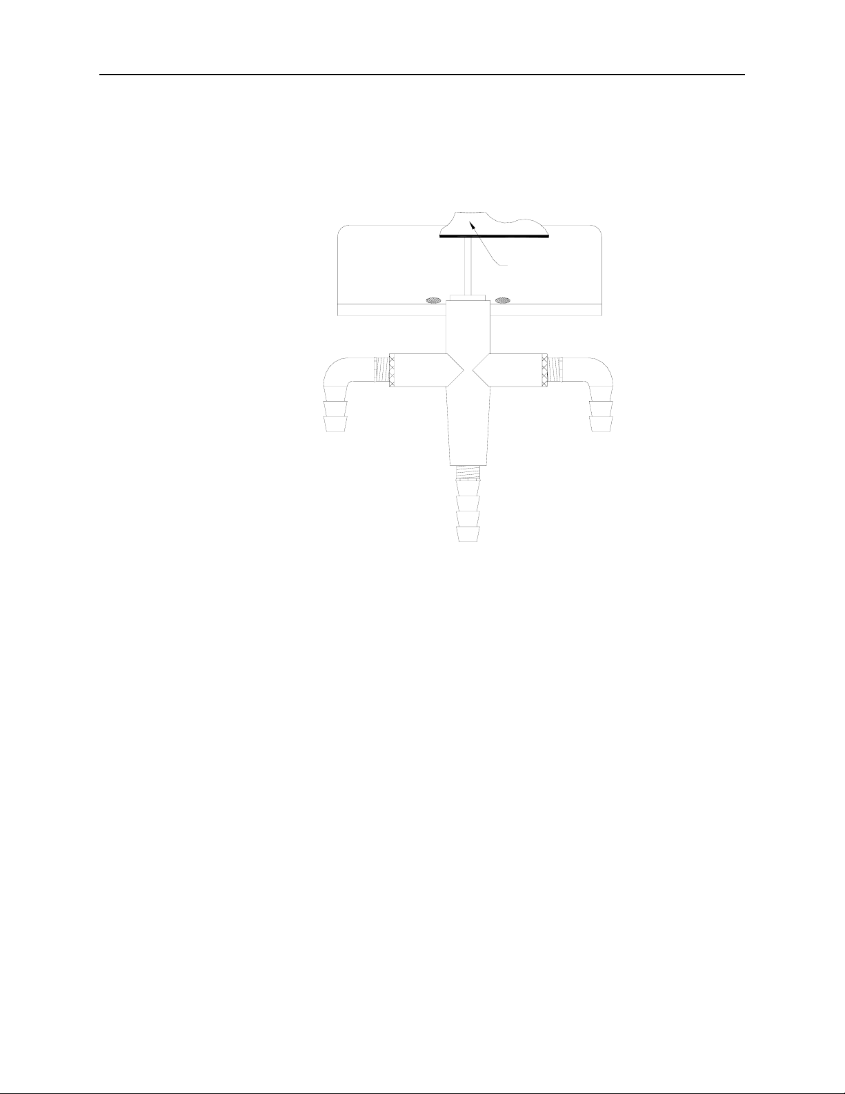
FUEL SELECT VALVE
If your boat is equipped with dual fuel tanks, you will have a manual fuel select valve
installed. This valve allows you to choose from which tank fuel will be consumed. Remember, as
the fuel is consumed and the fuel load redistributes the performance will be influenced. Select the
tank that allows the best performance for your boat.
Aluminum
Angle
Brass Elbow
1/4" Male X 3/8"
Barb
3-way Shut
Off Valve
To Aux
Tank
To
Engine
To Main
Tank
POLLUTION REGULATIONS
The U.S. Coast Guard defines restrictions on the discharge of oil or hazardous substances and
plastics or garbage in the “Federal Requirements for Boating and Boating Safety”. You should
have received this pamphlet when you registered your boat. Detailed below is a summary of those
regulations. You should read the pamphlet and become familiar with any local restrictions where
you operate your vessel. Passengers or crew members aboard your boat should also be notified of
these regulations.
3–3
G ENERAL INFORMATION
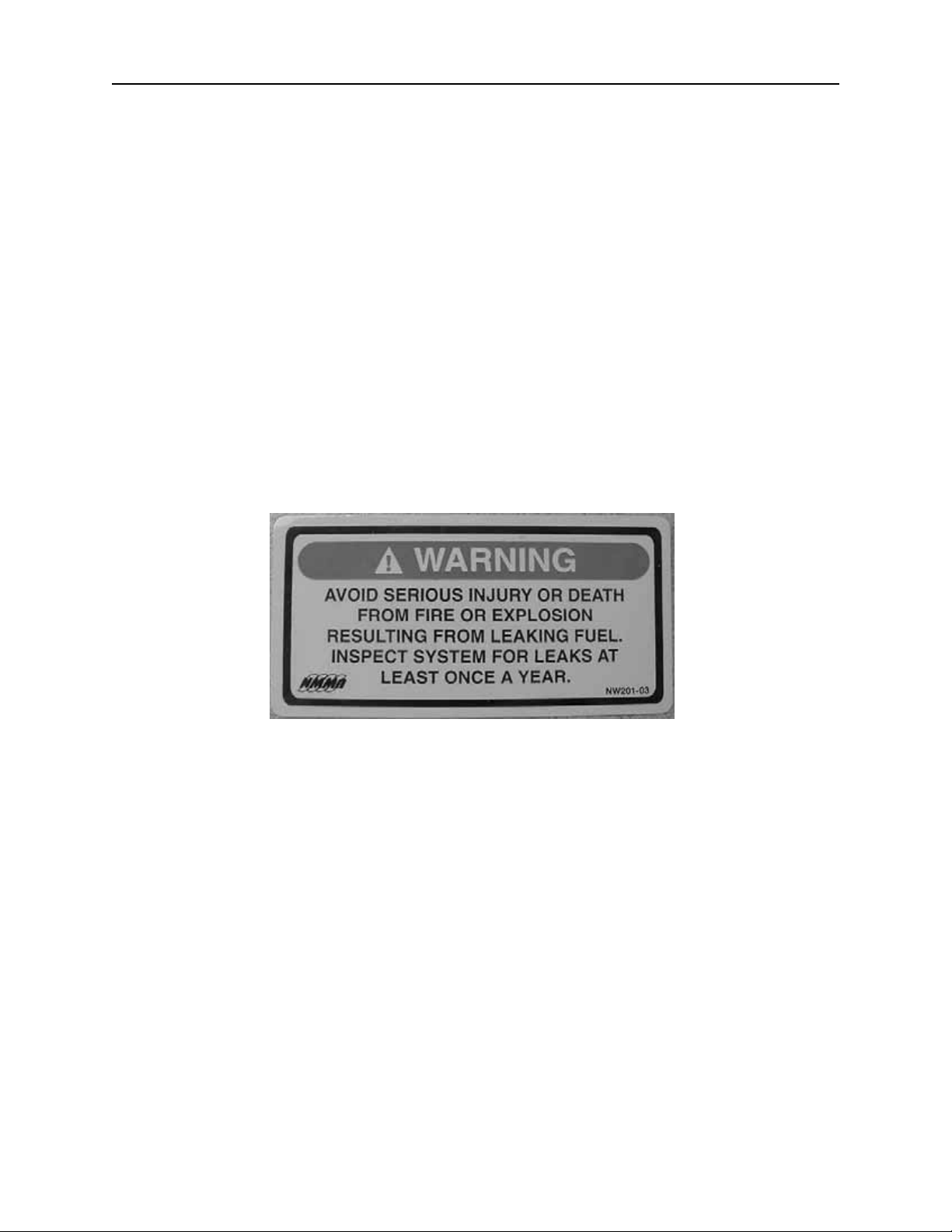
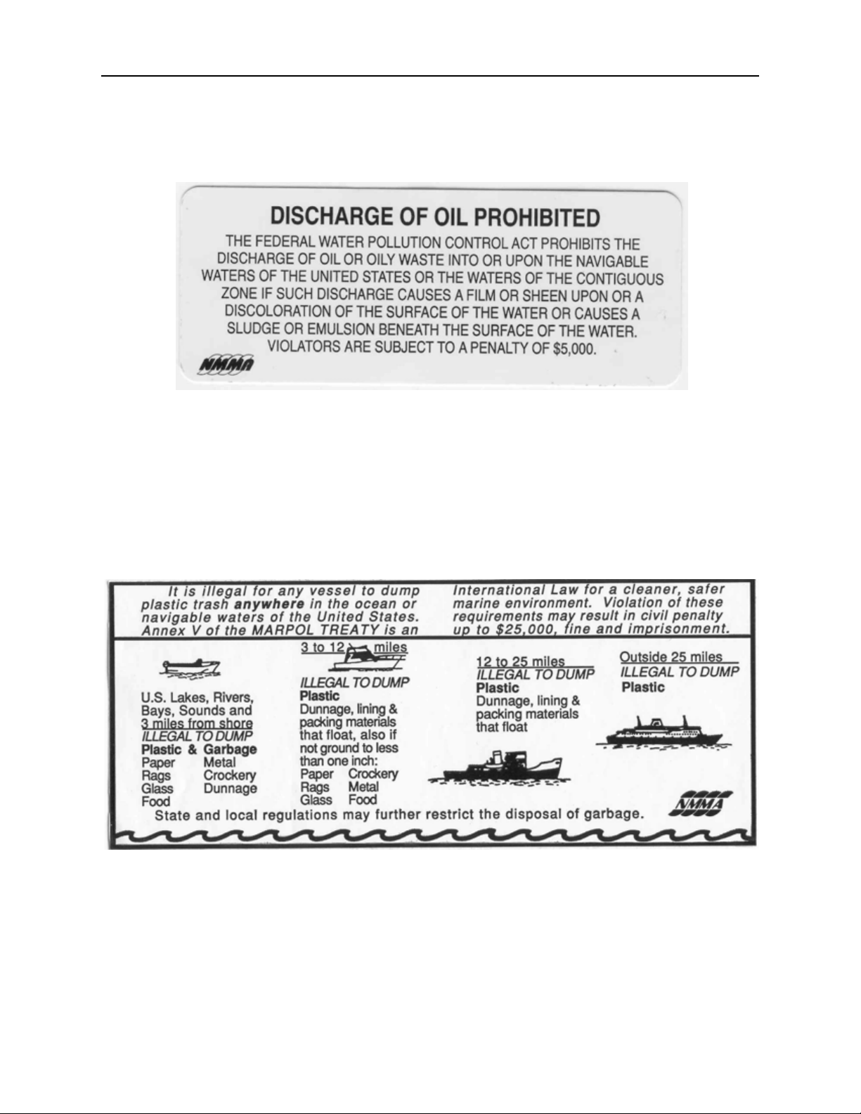
Discharge of Oil or Hazardous Substances
The Federal Water Pollution Control Act prohibits the discharge of oil or hazardous
substances, which may be harmful, into or upon U.S. navigable waters. Vessels 26 feet in
length or over must display a placard at least 5” x 8”. The placard should state the following:
Disposal of Plastics or Garbage
The MARPOL ANNEX V is the Act to prevent pollution from ships and other vessels.
Federal regulations prohibit the discharge of plastic garbage anywhere in the marine
environment. Plastic includes, but is not limited to: synthetic fishing nets, ropes, lines, straws,
six pack holders, styrofoam cups and lids, bottles, buckets and plastic bags. These regulations
also restrict the disposal of other types of garbage within specified boundaries from shore.
Any vessel 26 feet and over must display the placard below or a similar version which details
the regulations. The placard must be at least 4” x 9” and should be available from your dealer.
TRAILERING
The adjustment and balance of your boat on the trailer determines how easily your boat may
be transported. The tongue weight on the hitch ball should be 5-10% of the total weight of your
boat, motor and trailer. Tail-heavy loads cause swaying while trailering. The rollers and/or
bunkers of your trailer should be adjusted so that the weight is distributed evenly across the stern
and forward throughout the keel sections. Your dealer can help adjust your trailer properly.
3–4

G ENERAL I NFORMATION
Practice maneuvering the trailer; the trailer always backs in the opposite direction of the
vehicle. To maneuver the trailer, turn the steering wheel in the direction you want the trailer to go.
Familiarize yourself with this manual and all aspects of your boat prior to initial launch. At the
launch site, go through a pre-launch checklist. The list should be suited to your specific needs.
Trailering and relative information can be found on page 94 in Sportfish, Cruisers, Yachts
Owner’s Manual.
PREDEPARTURE
See the checklist on page 35 in Sportfish, Cruisers, Yachts Owner ’s Manual before starting
out.
CASTING OFF & APPROACHING THE DOCK
Unlike an automobile, the stern of your boat reacts first when turning. A turn to the right will
swing the stern to the left and vice-versa. Remember that turning your boat away from an object,
such as a dock, will tend to swing the stern toward that object. Reference procedures for casting
off and approaching the dock on page 42 of Sportfish, Cruisers, Yachts Owner’s Manual.
ANCHORING
Some factors that determine the size and type of anchor most suitable for your boat include
the size of your boat and the type of lake, sea or river bottom in your boating area. Sportfish,
Cruisers, Yachts Owner’s Manual has a list of tips concerning anchoring starting on page 46.
N O T I C E
It is illegal to tie your boat to navigational aids such as buoys and markers.
W A R N I N G
!
Never anchor off the stern of the boat especially in strong winds or currents. The weight of the
stern and flat surface to the seas can easily cause water to enter over the transom and swamp the
boat.
3–5

G ENERAL INFORMATION
TOWING
In the event of a mishap or power loss you may need to tow a boat or be towed. You should
not tow a boat larger than your own. Always use safety and good judgement when towing. Never
tow a boat if you are not equipped with the proper lines. Passengers should never grasp a towline.
It should be secured to the boat. See page 30 in Sportfish, Cruisers, Yachts Owner’s Manual.
Before towing a boat, make a bridle and tie it securely to the pad eyes on the transom with
enough slack to clear the engines. Pad the line wherever it comes into contact with the boat to
prevent chafing. Attach a tow line to the bridle so that it can slide from side to side to prevent too
much pressure on a single pad eye. The tow line should then be attached to the bow eye or to a
bridle on the towed boat. The tow line should be a minimum of twice the length of the towing
boat, the longer the better. Do not try to run in too close when passing the towline to the other
boat. Send either a light line or attach the towline to a life preserver to be pulled in. Be aware of
the other boat’s propeller.
The towed boat should always have someone at the wheel since the boat may swing off
course. Start the tow off slowly; a steady pull at a moderate speed should be used. It is important
to keep the slack out of the propeller area. Watch the action of the towing boat. If excessive slack
develops in the towline and contact is obvious, turn in either direction to avoid hitting the stern.
W A R N I N G
!
As a precaution, passengers on both boats should stay clear of the towline; lines under stress could
snap and fly in either direction causing injury.
SHALLOW WATER
Most boats that become grounded can be floated off with engine(s) tilted to reduce the draft at
the transom. With motors tilted, try rocking the boat from side to side to break the suction of mud
from the keel. Move passengers or heavy objects from the point where the boat is grounded. Do
not lower or start the engine(s) until the boat is clear of the ground. Refer to page 53 in Sportfish,
Cruisers, and Yachts Owner’s Manual.
C A U T I O N
!
Do not lower or start engines if the propeller is in mud or sand. Wait until the boat is refloated to
avoid damage to the cooling system of your engine.
Be mindful of water level fluctuations when boating in water with tidal changes. If you are
grounded on an incoming tide, you can wait until the tide is high enough to refloat your boat.
However, on an outgoing tide, quick action should be taken to refloat your boat. If this is not
possible, set an anchor to keep the boat from becoming driven further aground. Set the anchor to
counter the action of the wind or current. The anchor, in some cases, can also be used to pull the
boat free.
Many inland areas have rocks and stumps which could crack or puncture a fiberglass hull. Be
familiar with the boating area, and use caution in shallow water.
3–6

G ENERAL I NFORMATION
WINDLASS
Anchoring can be less laborious if your boat has a windlass accessory . If your boat is equipped
with a windlass, reference your windlass Operation Manual for instructions.
GENERAL INFORMATION ON BOAT HANDLING
The best method of learning how to handle and obtain the best performance from your boat is
to practice and experiment. After several hours of operation, you should experiment with the
throttle settings to discover the setting that will be the most comfortable and economical range for
your particular load conditions.
We suggest that you make a speed and RPM chart to obtain the most economical operation.
Operate the boat at various speeds and check the fuel consumption. Compute the amount of
operating time remaining when the fuel gauge has only one bar remaining on the display. Make a
log of this type of information and have it available when using your boat. Other statistics you
may want to determine could include the following:
• Minimum speed for effective steering.
• Turning radius at different speeds.
• Response to steering at low speeds.
• Accelerating and deceleration rates.
• Time and distance to bring the boat to a stop at different speeds.
• Control of the boat using both engines in close quarters.
Also read the section in Sportfish, Cruisers, Yachts Owner’s Manual beginning on page 49 for
information on safe operating speed.
TWIN ENGINE BOATS
T win engine boats are easier to maneuver than si ngle engine crafts. However, they still require
practice to ensure comfortable operation. The boat will run ahead or backward in a straight line
when both engines are working together at the same speed. The engines also can be used to steer
to port as well as starboard. Moving ahead on one engine will cause the bow to swing away from
the running engine side and to move forward at the same time. Backing up with one engine will
cause the bow to swing toward the running engine side and the boat to move backward. Running
one engine ahead and one engine astern will cause the boat to turn end-for-end in little more than
its own length. Running both engines in the same direction at different speeds will cause the boat
to move in the direction dictated by the faster engine but its influence will be modified by the
slower engine.
3–7
G ENERAL INFORMATION
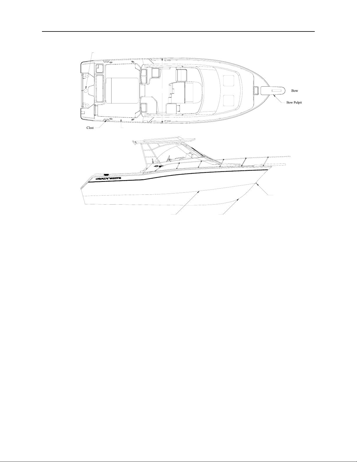
COMMONLY USED NAUTICAL TERMS
Access Plate
Port Side
Stern
Abeam - a line perpendicular to a
boat’s keel
Access Plate - a removable,
watertight cover that provides quick
entry to enclosed areas for
maintenance or visual inspection.
Aft - toward the rear or stern of the
boat
Beam - the greatest width of the
boat
Bilge - the lower interior area of the
hull
Bow - the forward section of the
boat
Bow Eye - a U-shaped hull fitting
used to attach the trailer winch to the
boat
Bulkhead - vertical partition in the
boat
Chine - point where the topside and
bottom of the boat join
Cleat - deck fitting with arms or
horns on which lines are fastened
Beam
Gunwale
Starboard Side
Deck - upper structure which covers
the hull
Draft - depth of water required to
float a boat
Fathom - a depth measurement
equal to six feet
Freeboard - distance measured
between waterline and deck
Gunwale (Gunnel) - point where
the deck and hull join
Hatch - an opening in the deck to
provide access below
Headroom - vertical distance
between the floor and over head
structure or canopy ceiling
Hull - major component that
provides a watertight platform
buoyant enough to float a craft and
its load
Keel - the major longitudinal
member of a hull -the lowest
external portion of the boat
Knot - a measurement of speed
equal to nautical miles per hour
Bow Eye
KeelChine
Lee - the side that is sheltered from
the wind
List - a tilt or lean to one side
Port - a term designating the left
side of the boat when facing forward
Scupper - holes permitting water to
drain overboard from deck and
cockpit
Sheer - curve or sweep of the deck
as viewed from the side
Starboard - a term designating the
right side of the boat when facing
forward
Stern - rear of the boat
Stringer - longitudinal members
fastened inside the hull to add
rigidity and strength
Wake - the movement of water
created by a moving boat
Windward - side facing the
direction of the wind (against the
wind)
3–8

PERFORMANCE
Chapter 4: Performance
PERFORMANCE FACTORS
Maximum performance is dependent on many factors and cannot be guaranteed. These factors
will vary with changing conditions. Some of these factors are listed below. Reference the troubleshooting guide on page 65 in Sportfish, Cruisers, Yachts Owner’s Manual for additional
suggestions on adjusting performance.
Engine Efficiency
Engines operate most efficiently when they are properly tuned, and the props are in good
condition. Efficiency will decrease if normal care and maintenance is not performed.
Neglecting the engines will cause power to drop and speed to decrease. In addition, expensive
repairs may become necessary. Be sure to follow all instructions in the engine operation
manual(s).
Weather Conditions
Weather conditions sway engine performance. Barometric pressure and humidity affect
horsepower. A change of weather could amount to a 10% loss in horsepower on some hot
days.
Load Distribution
A decrease in performance will be noted when gear, equipment, passengers, and fuel are
added. This extra load will affect the performance of your boat according to the distribution of
the weight. Another type of extra load that could affect performance is the accumulation of
water in the bilge. Keep the bilge dry to eliminate this type problem.
Marine Growth
Maximum performance is obtained only when your hull bottom is clean. Marine growth on
the bottom of the boat will increase resistance and decrease speed. These conditions will also
increase fuel consumption. Reference “Cleaning” on page 6–1 for more information on
cleaning your hull bottom.
Trim
The outboard engines are equipped with power tilt and trim mechanisms. The purpose of
power tilt is to raise the engine(s) for launching, loading or trailering. Power trim may be
used to adjust the boat’s planing performance and running attitude. See power trim, page 52
and 72, in Sportfish, Cruisers, Yachts Owner’s Manual.
Trim refers both to the weight distributions inside the boat and to the angle of thrust of the
engine. The angle of thrust of the engine forces the bow up or down. The trim tabs on your
boat also control the trim of the boat, similar to the po wer trim. Refe r to the Trim Tabs section
in Chapter 8 for additional information.
4–1
P ERFORMANCE
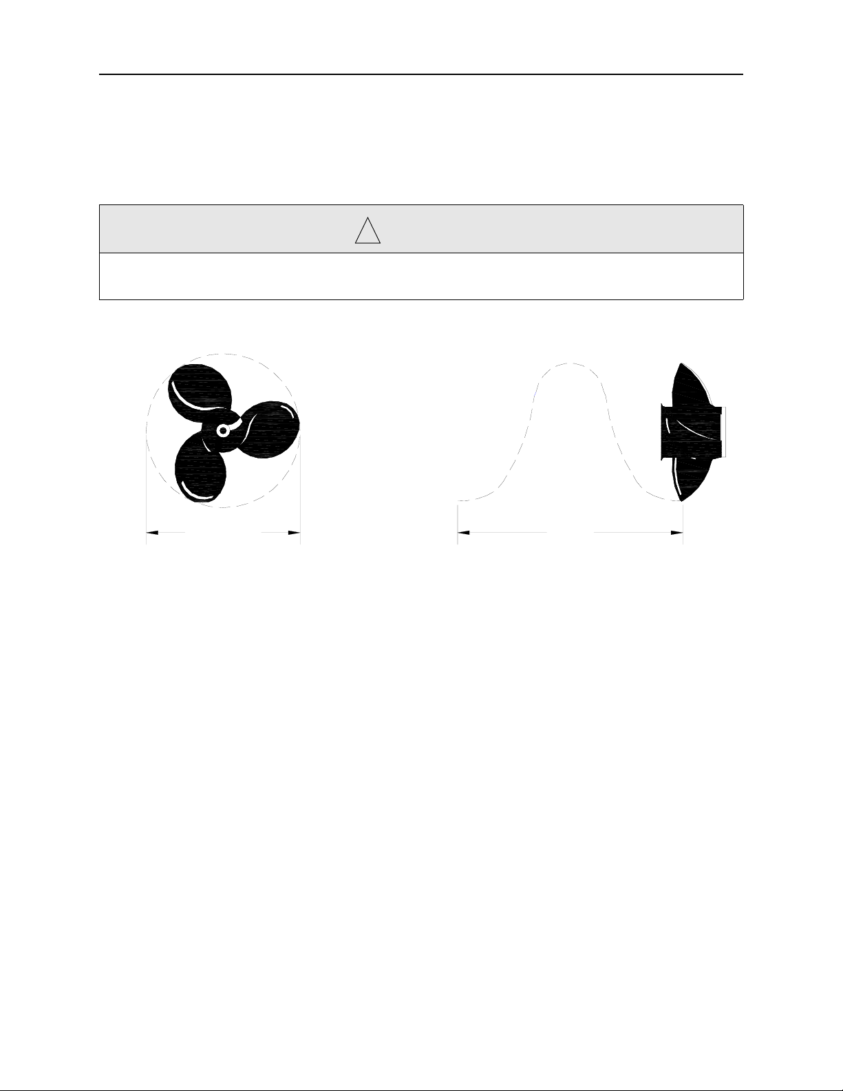
Propeller
The condition of your prop has a major influence on the performance of your boat. Your
engine(s) should be equipped with the best size prop for normal conditions. Unusual uses or
weight conditions may require special props. A damaged prop can affect your boat's top
speed, cause vibrations, create a sudden drop in RPMs or even increase fuel consumption.
C A U T I O N
!
Stay within the engine manufacturer's maximum and minimum RPM ranges when replacing
props. This information is located in your engine manual.
PitchDiameter
Diameter = 14 Pitch = 14
Diameter and pitch are the two basic dimensions of a propeller. Diameter is the distance
across the circle made by the blade tips as the propeller rotates. Pitch is the theoretical (not
accounting for slippage) forward distance the propeller would move in one revolution. An
example of a propeller dimension would be 14 X 17 for a propeller having a diameter of 14”
and a pitch of 17”.
4–2

PERFORMANCE
PROPULSION SYSTEM – OUTBOARD
The engine manufacturer supplies all vital information concerning your engine(s) in the
Operation and Maintenance Manual(s). Details of important engine functions such as the
lubrication system, cooling system, and alarm/monitoring system are outlined in these manuals.
Your familiarization with this engine reference material will result in the proper usage and service
essential for safe and enduring engine performance. These manuals are included with the Owner’s
Packet.
D A N G E R
!
Do not inhale exhaust fumes! Exhaust contains carbon monoxide — a dangerous gas which is
potentially lethal.
W A R N I N G
!
Do not attempt to service any engine or drive component without being totally familiar with the
safe and proper service procedures. Certain moving parts are exposed and can be dangerous.
C A U T I O N
!
Do not paint the outboard motors with anti-fouling paints designed for boat hulls. Many of these
paints can cause severe damage to the engines.
ENGINE WARRANTY
A warranty registration card is included with all engine manuals. It should be completed and
returned to the engine manufacturer as soon as possible.
4–3

P ERFORMANCE
STEERING
Most outboard engines are equipped with an adjustable rudder trim tab. This trim tab should
be adjusted to balance the steering at the speed which you travel most frequently. Variations in
speed, boat load or engine trim will cause the steering to pull in one direction. If the boat pulls to
the left, adjust the trim tab to the left and vice-versa.
• Hydraulic Steering
Hydraulic steering systems (not to be confused with power steering) require regular
preventative maintenance for continued safe and reliable operation. The oil level in the helm
pump must be maintained within acceptable operating levels. A low oil level will allow air to
get into the steering system and result in unresponsive steering. The oil level should always be
within 1/2 inch from the base of the fill hole, located on the front top portion of the helm
pump. Check the entire steering system regularly for oil leaks. Unobserved leaks over a period
of time will result in unresponsive steering and possibly loss of steering. Refer to the steering
manual for specific recommendations and additional maintenance requirements.
Any slow or sudden change in the “feel” of your steering system indicates an immediate need
for a thorough inspection. All repairs and replacements to steering systems should be made
only by a qualified marine technician.
• Tilt Steering
This feature enables the operator to tilt the wheel up or down. Refer to the steering system's
manual for information on oil levels with hydraulic tilt steering.
4–4

PERFORMANCE
THROTTLE/SHIFT CONTROL
The throttle/shift controls located at the helm station control the flow of fuel to the engine.
They also act as gear shift levers to control the forward and aft thrust of the propellers.
The middle position of the throttle control is the neutral position. Move the control forward to
engage the shifting mechanism which creates a forward thrust of the propeller. Advance the
forward movement to increase the fuel flow to the engine and boost the forward lunge.
Move the control lever aft of the neutral position to reverse the shift mechanism and create a
reverse thrust of the propeller. Increase the aft movement to increase the reverse thrust.
Remember that propellers are designed for maximum forward thrust; so, reverse thrust will not be
as efficient.
All controls have a neutral safety mechanism. This mechanism will not allow the engine to
start when the control is in gear. You may use the neutral lock out feature on the control handle to
increase the flow of fuel to the engine while remaining in the neutral position.
Neu tral Lo c k-o ut B u tton
for Mechanical Shifter is
located on starboard handle.
Reverse the shift mechanism to stop a boat that is moving forward. This change in direction
will provide a “braking action” and slow the boat.
C A U T I O N
!
The braking action causes a wake which may wash over the transom and flood the boat if the
vessel is moving too fast. Allow engine RPMs to decrease before shifting into reverse.
If your boat has mechanical controls, there will be control cables that operate the shift and
throttle functions on the engine. If your throttle or shift cables need replacing, use the same style
and length as the original equipment.
4–5

P ERFORMANCE
4–6

I NSTRUMENTATION AND S WITCHES
Chapter 5: Instrumentation and Switches
YAMAHA INSTRUMENTATION PANEL
Grady-White installs full Yamaha Command Link instrumentation on pre-rig boats. The
instruments are powered by the ignition key(s) and will operate when the ignition switch(es) is in
the “on” position.
DIGITAL SPEEDOMETER AND FUEL MANAGEMENT
• Fuel Level
This feature indicates the gas tank(s) fuel level. Remember two things when reading this
gauge:
• The accuracy of your gauge varies with the attitude of your boat in the water (trim or list).
• The fuel pickup tube inside the gas tank is not capable of withdrawing all of the fuel from
the tank.
For these reasons, never operate your boat at extremely low fuel levels.
• Fuel Economy
This feature indicates the engine’s fuel economy in miles per gallon.
• Fuel Consumption
This feature indicates the fuel consumption in gallons since the feature was last reset. For twin
engine applications, this may be monitored individually or as a total.
•Fuel Flow
This feature indicates the fuel flow through the engine(s) in gallons per hour.
• Low Fuel Warning Indicator
This feature indicates the amount of fuel in gallons per hour flowing through the engines.
Each engine may be monitored separately or a total amount displayed.
5–1

I NSTRUMENTATION AND SWITCHES
• Speedometer
This feature indicates boat speed in miles per hour, knots per hour, or nautical miles per hour.
On boats with V8 engines, this gauge must be interfaced with a GPS.
• Trip Distance Meter
This feature indicates the distance traveled in miles or nautical miles since the meter was last
set.
DIGITAL TACHOMETER
• Revolutions Per Minute (RPM)
This feature indicates the RPM using 100 RPM intervals. Consult your engine Owner's
Manual for the recommended operating RPM range.
• Trim Position
This feature indicates the angle of thrust of the engine. See “Trim” on page 4–1 for
adjustment recommendations.
• Battery Voltage Indicator
This feature indicates the battery charge when the engine is off and indicates the alternator
output when the engine is running. A reading of 12 or 13 volts is normal indicating a fullycharged battery. Readings below 11 indicate a weak battery which may not start the engine. A
reading of 13 to 15 volts when the engine is running is normal. Readings over 15 volts may
indicate regulator problems. Low or fluctuating readings may indicate loose connections or
trouble in the regulator and alternator circuit.
• Cooling Water Temperature with Warning
This feature indicates the temperature of the cooling water circulating through the engine and
warns you when the temperature exceeds the recommended operating range indicated by your
engine owner's manual. Should you receive this warning, immediately shut off your engine to
prevent damage. Overheating is often caused by obstruction of your engine's intake on the
lower unit. Check this water intake first if you experience trouble.
• Hour Meter
This feature records the cumulative number of hours the engine has been in use.
• Tripped Hour Meter
This feature indicates the number of hours the engine has been in use since it was last set.
• Oil Pressure with Warning
This feature indicates the engine oil pressure with a warning for low oil pressure. Refer to
your engine owner's manual for information regarding engine oil and oil pressure.
5–2

I NSTRUMENTATION AND S WITCHES
SWITCH PANEL
At the helm station you will find an accessory switch panel. Not all boats are equipped with
the same accessories. Consult your dealer for specific information or questions on the accessories
included on your boat. More detailed descriptions of switch functions are located in Chapter 8 of
this manual.
M
COCKPIT
LIGHT
NAV/
ANCHOR
WASHDOWN
LIVEWELL
WATER
PRESSURE
MACERATOR
HORN
WIPER
FWD
BILGE
AFT
BILGE
ELEC
BOX
ACC
This represents a generic switch panel layout. Actual panels will
differ depending on the boat model and optional accessories installed
during manufacturing.
5–3

I NSTRUMENTATION AND SWITCHES
5–4

M AINTENANCE AND S ERVICE
Chapter 6: Maintenance and Service
GENERAL
The amount of maintenance required to keep your boat operating properly and to maintain the
appearance is dependent on how the boat is used, amount of usage, salt or fresh water, geographic
location, etc.
Your hull and deck are constructed by the “hand lay-up method” using the highest quality
fiberglass mat and woven roving. This method of construction ensures a proper fiberglass-to-resin
ratio and uniform thickness resulting in a much stronger boat than those constructed of “chopped
glass”. This process ensures your Grady-White is the strongest, most durable fiberglass boat
possible.
Keep the bilge area clean and dry. Leaks found early and corrected will less likely cause
damage. Do not allow grease, grime, and dirt to build up.
While proper maintenance of your boat is a source of pride, it is also key to maintaining your
boat's value. A few simple steps will keep your fiberglass Grady-White looking showroom bright
for years.
EXTERIOR FIBERGLASS FINISH
The exterior finish of your Grady-White is a thin layer of resin with a finished color pigment
called gel-coat. It is used for cosmetic purposes and makes routine maintenance relatively simple.
Although gel-coat has a hard smooth surface, it does contain microscopic pores that will allow
surface discoloration if not kept clean.
Maintenance
Normal exterior finish maintenance of your Grady-White is similar to the care you would give
your automobile. Do not use caustic, highly alkaline cleaners or those containing ammonia.
These cleaning agents may darken gel-coat. The resulting stain is a chemical reaction and can
be removed with a rubbing compound followed by waxing. Also, using common household
bleach (chlorine) may damage the gel-coat finish just like bleach can damage clothing with
colors. Bleach impacts solid colors by causing blushing or fading and for this reason should
not be used on gel-coat.
Cleaning
The best way to prevent discoloration and soil build-up is to hose the boat with fresh water
after each outing or on a regular basis. This build-up is the result of use and environmental
pollutants. Clean the boat regularly with a mild household detergent and plenty of fresh water.
Avoid strong detergents, citrus based cleaners, or bleaches. These products are potentially
harmful to the appearance and durability of your boat’s gel-coat. Always read the label before
using any cleaning product to make sure it says safe for use on fiberglass finishes. Use a
sponge on smooth surfaces and the deck. A brush can be used on the nonskid areas. Rinse
away all grime and residue.
6–1

M AINTENANCE AND SERVICE
Finish/Waxing
Gel-coat will age or dull naturally due to constant exposure to the natural environment and
pollutants. Discolorations are shallow in depth. Factors that will affect the rate of
discoloration are: the sun, pollution, old wax accumulation, and the salt content of water.
Polishing compound (fine abrasive) or rubbing compound (coarse abrasive) is recommended
for use on fiberglass finishes to remove scratches and stains or restore severely weathered
surfaces. These products can be applied by hand or mechanical means. The process below will
help restore fiberglass finishes:
•Clean the affected area with a good detergent.
•Remove stubborn stains or discoloration by gently wet sanding the affected areas with 600
grit “wet or dry” sandpaper. ALWAYS SAND IN ONE DIRECTION. Use plenty of
water and sand curves in the same direction. Dry the area to make sure all the discoloration
has been removed. Repeat this process if necessary.
•Buff using a polishing compound suitable for fiberglass, an electric buffer (1750-1800
RPM), and an 8-inch lamb’s wool pad.
C A U T I O N
!
Keep buffer moving. Do not allow it to rest in one spot. Heat build up will quickly distort the
surface.
C A U T I O N
!
Compounding too often or excessive compounding can wear away the gel-coat.
•When buffing is complete, wash away compound with clear water and dry the area.
•Once the area is clean it may be waxed. This will enhance the gloss while providing a seal
to retard staining or soil accumulation.
•See a local dealer for advice on wax for your boating region. The wax film will seal the
pores as well as enhance the looks of your boat. DO NOT wax surfaces that may be
walked on; they will become slippery. While waxing your boat, inspect the surface for
any damage. Have the damage corrected as soon as possible.
6–2

M AINTENANCE AND S ERVICE
Repairing
Though gel-coat is a very durable material, it is susceptible to scratches, blistering, and weblike cracking (crazing) over time. It is elastic enough to withstand strong blows while flexing
with the hull's movement. Gel-coat problems are cosmetic and will not effect the structural
integrity of your boat.
Some gel-coat damage and imperfections such as nicks and scratches can be repaired by
obtaining a color match patch kit. This kit can be purchased through your Grady-White dealer .
Acetone, the most suitable cleaning agent for gel-coat, can also be acquired through your
dealer. Instructions are included in the patch kit.
W A R N I N G
!
M.E.K.P. (Methyl ethyl ketone peroxide), gel-coat and acetone are flammable and hazardous
chemicals that must be handled properly. Follow instructions carefully. After the gel-coat is
catalyzed, it will soon heat up and put off fumes. When finished with catalyzed chemicals, or if
they start to build up heat, submerse completely in water until cool.
BOTTOM PAINT
If your boat is left in the water for more than a few days at a time, the hull bottom below the
waterline should be painted with anti-fouling paint to protect it from marine growth and barnacles
that hinder performance. Since anti-fouling paint slowly dissolves, yearly inspection and cleaning
of the hull bottom to prevent marine growth is advised. Repaint when necessary. To help prevent
blistering, use an epoxy barrier coat to be applied in conjunction with the anti-fouling paint.
CANVAS
Grady-White’s canvas is made using the highest quality vinyl and latest sewing techniques.
The canvas will not be completely leak proof. The seam holes in your canvas may stretch and tend
to leak. However, you can correct this problem by applying *Apseal® or Uniseal™ to the seams.
Please understand that Grady-White does not warrant the fit and design of the canvas to be
entirely watertight.
Maintenance
To maintain your boat's top and other canvas follow these guidelines:
Fabric should be cleaned regularly to prevent the buildup of soil and soil penetration of the
fabric. Simply brush off any loose dirt, hose down canvas and clean with a mild solution and
warm water . Do not use petroleum-based or ammonia cleaners on canvas or clear vinyl as they
will yellow. For heavily soiled fabric, remove the top from the frame. Soak the fabric in a
solution of 1/2 cup of Clorox™ and 1/4 cup of Ivory or Lux soap per gallon of warm water.
Let soak until mildew and stains can be brushed out with a common kitchen brush. Rinse
thoroughly with cold water until all soap is removed. Allow fabric to air dry completely. DO
NOT STEAM PRESS OR DRY IN AN ELECTRIC OR GAS DRYER. This will damage
the canvas fabric. Water repellent was applied to your canvas during manufacturing. The
repellent may have diminished after extended cleaning. Re-treatment of the fabric is
recommended. Do not use wax-based products. Use a water based repellent like *Apseal® or
Uniseal™. Scotchguard® is effective for short-term use only.
6–3

M AINTENANCE AND SERVICE
Snaps And Zippers
To protect the snaps and zippers on your boat’s canvas and cushions from corrosion and
binding, Grady White includes a snap/zipper assist tool and a tube of lubricant (E-Z Snap™)
in your owner’s packet. The lubricant, manufactured by IOSSO (part number 10909), should
be applied per the manufacturer’s directions during the initial use of your canvas and
cushions. The lubricant should be reapplied every 3 months or sooner depending on your
boating environment and usage. The snap/zipper assist tool included in your owner’s packet
should be used whenever you remove the canvas, cushions, or operate the zippers to prevent
damaging or tearing the material. Contact your dealer if you need to replace your assist tool or
reorder the lubricant.
Vinyl
•Clean clear vinyl thoroughly with denatured alcohol and apply a protective layer of clear
wax. Do not use paste wax, as it will turn the vinyl yellow. This process should be repeated
as necessary to maintain the protective wax coating.
•Store and secure canvas before trailering.
•Dry all canvas before storing to prevent mildew.
•Remove the top, front, and side panels. Roll them for storage. This is necessary to prevent
the front and side vinyl pieces from cracking. NEVER FOLD THESE PIECES!
Storage
Consider the following steps when putting your folding top canvas option in the stored
position:
•Fold the top and zip it into the canvas cover provided.
•Pivot the covered top into the stowed position on the foredeck. The canvas cover is
equipped with a strap on each side and an eyelet in each strap. Place the eyelets over the
male fasteners located on the port and starboard foredeck.
•Twist the male fastener 90 degrees to engage.
C A U T I O N
!
Secure the folded top when in the stowed position to prevent damage or the loss of your canvas.
6–4

M AINTENANCE AND S ERVICE
UPHOLSTERY
Your exterior vinyl upholstery may be cleaned with a mild solution of household detergent
and fresh water. Commercial cleaners for vinyl also work well. Since the seams of your exterior
upholstery are not waterproof, your upholstery should be stored in the cabin or covered when not
in use. Exterior cushions will trap moisture between themselves and the gel coat. If a cushion is
not removed to allow the moisture to dry, blistering of the gel coat may occur. Cockpit bolsters
may be removed if you desire. These bolsters clip onto brackets mounted to the deck structure.
Screws are then installed through the underside of the bolster to hold them in place. Most cabin
cushions are removable and may be dry-cleaned or steam cleaned. Some cabin cushions are of a
Herculon-type fabric and may be cleaned with upholstery cleaner.
C A U T I O N
!
Do not machine wash cabin fabrics.
DURATRIM/POLYETHYLENE/PLEXIGLASS/VINYL
In the cockpit area of your boat, duratrim, plexiglass, and vinyl are used for trim and
polyethylene is used for the toe rails and rod racks. Routine maintenance for duratrim and vinyl
should include regular cleaning with soapy water and the application of a surface protector at least
twice per year. Polyethylene can be cleaned with products such as 409 or any spray and wipe
cleaner. Plexiglass, used to cover your instruments’ radio box and also as interior storage doors,
can be maintained by use of a glass cleaner and a soft cloth.
SCUPPERS
Grady-White boats have self-bailing cockpits meaning water on the cockpit floor drains by
gravity through large aft scuppers and not into the bilge. The aft drains (scuppers) have an
external scupper flap assembly that restricts the flow of water back into the boat. Inspect the flaps
periodically to make sure they are free of debris. The scupper flaps may need periodic
replacement if the rubber becomes damaged or no longer seals properly in the thru-hull.
CAULKING/GASKET
Deck fittings, bow rails, windows, hatches, etc. have been caulked or gasketed with the
highest quality material to ensure a waterproof joint with the boat. However, the working action
of normal use will tend to flex the joint and eventually break down the seal between them.
Periodically inspect the caulking or gaskets for leaks. Recaulk or replace the gaskets necessary, or
have your dealer do the repair.
HARDWARE/HARDTOP FRAME/STAINL ES S STEEL RAILS
The hardware on your Grady-White is made of laboratory grade 316 stainless steel and needs
regular cleaning to maintain its “less staining” properties. The key to maintaining your stainless
steel is to keep it clean with a mild solution of soap and FRESH water. Remove salt or dirt from
your stainless steel on a regular basis.
6–5

M AINTENANCE AND SERVICE
HARDWARE MOUNTING
Ensure all holes are sealed properly when mounting hardware in the boat surface. Sealing will
prevent water leakage. This is crucial in fiberglass areas that have been reinforced with plywood.
A hole sealed improperly allows water inside the fiberglass leading to saturation of the plywood
reinforcement.
MAINTENANCE PROCEDURE FOR ANODIZED ALUMINUM COMPONENTS
(Lean Bars, Rod Holders, T-Top and Hardtop Frames, Outriggers, Etc.)
Due to the nature of anodized aluminum and the harsh exposure conditions of the marine
environment, it is important to follow a required maintenance procedure. Failure to follow a
preventative maintenance procedure will most likely result in aluminum pitting.
These parts must be washed periodically with a very mild soap and water solution. Grady
White recommends washing with a mild soap (such as Ivory Liquid) after each use and every two
to three weeks if stored in an outside marine environment. Strong cleaners and soaps must not be
used. Never use abrasive cleaners or products that contain chlorine bleach. These products can
remove the anodized coating.
Give special attention to the upper tubes of a hardtop or T-top frame. The area just below the
top is shielded by the canvas or fiberglass top and does not receive the natural rinse that rainwater
provides. Failure to thoroughly clean and maintain this area will allow contaminates that attack
the anodized aluminum to remain on the frame.
For maximum protection, coat parts with a non-abrasive metal protector. The best protectors
will displace moisture, remove contaminates, and leave a wax film protecting the anodized
aluminum. Follow the application guidelines for the product you choose. A sample of one metal
protector has been provided with your boat.
METAL PROTECTORS:
Boeshield T-9 Aluma Guard Premier Polish
PMS Products Inc. Rupp Marine, Inc. Aquatech
76 Veterans Dr. Unit 1104761 Anchor Ave. 6726 Netherlands Drive, Suite 200
Holland, MI 49423 Port Salerno, FL 34992 Wilmington, NC 28405
800-962-1732 561-286-5300 800-853-7760
C A U T I O N
!
Do not use abrasive cleaning products, pads, steel wool or steel brushes. These products will
damage the finish.
FUEL SYSTEM MAINTENANCE
To determine whether a fuel flow problem is in your fuel system or your engine, follow this
simple method. Connect a six-gallon portable tank to the engine and operate the engine. If the
problem persists, the likely cause is with the engine itself. If the problem goes away, the source
must be in the boats’ fuel system. One component that should be inspected if a restriction occurs
is the anti-siphon valve. If fuel does not flow properly through this part, it must be cleaned and/or
replaced. DO NOT remove the anti-siphon valve and replace it with a regular barb.
6–6

M AINTENANCE AND S ERVICE
Annually conduct a detailed inspection of fuel system components, especially those hidden
from routine inspection. Replace any fittings, deteriorated hoses, clamps or connections
immediately. Fuel filter/water separators should be replaced at least annually.
FUEL TANK COMPARTMENT
The fuel tank compartments need to be rinsed periodically especially when used in a saltwater environment. Dirt accumulation attracts salt, creating salt crystals. Salt crystals can corrode
most metal surfaces if left untreated over a period of time. T o help protect your fuel tank from rust
and corrosion, rinse the compartment with FRESH water. After rinsing, make sure all water is
drained from the compartments. Remove the access plates from fuel tank lids and inspect this area
for leaks or unsecured lines.
The access plates on your fuel tank lids keep the fuel compartments sealed. Over time, the
opening and closing of these plates causes the o-rings to wear-out. Replace these o-rings as
necessary to maintain the watertight integrity of the plates.
SHOWER SUMP
A shower in the head compartment drains into a contained “sump” which is used to prevent
hair, soap, scum and bacteria from accumulating in the bilge and creating odors. This sump
should be cleaned regularly. The sump pump box contains a filter. Remove the filter and rinse
with water to clean. The filter should always be installed when using the shower to prevent the
sump pump from becoming clogged.
BATTERIES
Proper battery power is essential to the operation of your vessel. For this reason, Grady-White
has carefully chosen a battery with cranking ability and reserve capacity sufficient to meet your
needs. The factory installed Deka Marine Master 27M6 battery is a maintenance free battery . This
battery utilizes an exclusive demineralized electrolyte and maintenance free calcium alloy grids.
These features reduce water loss and extend the life of the battery. However, this battery is
maintenance accessible in the unlikely event a charging malfunction occurs. Grady-White
recommends the Deka 27M6 product for all replacement applications. If your boat is equipped
with batteries not installed at the factory, consult with the battery manufacturer for proper care
and maintenance instructions and the engine manufacturer for appropriate battery specifications.
Batteries must be secured in a non-metallic tray to contain electrolyte spills. An insulated boot
should cover battery terminals. Keep terminals clean by scrubbing them with a stiff brush and a
mixture of baking soda and water. Afterwards, apply a light coat of grease or corrosion
preventative.
Batteries contain sulfuric acid, a harmful and potentially volatile chemical. When handling
batteries, exercise caution and follow these guidelines.
• Avoid contact between skin, eyes, or clothing and sulfuric acid.
• Protective gloves, eye wear, and clothing should be worn when servicing to
minimize risk to yourself.
• Batteries produce explosive gases. Keep sparks, flames and cigarettes away.
Ventilate when charging or using in an enclosed space.
• Keep out of reach of children
6–7

M AINTENANCE AND SERVICE
This is not a complete set of guidelines. It is your responsibility to safely maintain your
batteries and avoid injury. Use good judgement and remain alert to prevent an accident. In the
event of an accident or exposure to electrolyte, immediately seek prompt medical advice or
attention.
W A R N I N G
!
Do not allow any electrically conductive material to make contact with both the positive and
negative terminals at the same time (i.e. a hand tool used when disconnecting and reconnecting
battery cables). A short of this nature can cause severe burns and create dangerous sparks which
could result in personal injury and/or property damage.
C A U T I O N
!
When disconnecting and reconnecting battery cables, the black cable must be connected to the
negative terminal and the red cable must be connected to the positive terminal. Reversing these
connections will immediately damage your system.
Never disconnect the battery when the engine is running. This can cause damage to the charging
system. When replacing your battery , use the same brand and type as the factory installed battery.
If this is not available, reference your engine Owner’s Manual for r ecommended b attery type and
required performance specifications.
6–8

M AINTENANCE AND S ERVICE
LIGHT BULB REPLACEMENT GUIDE
The following chart provides identification of replacement light bulbs for your Grady-White.
All of the lights shown may not be used on every model boat. If you have difficulty finding
replacement bulbs under the part numbers listed, contact your Grady-White dealer for further
assistance. Always use the specified replacement bulb. Improper substitution my result in
electrical malfunction, insufficient lighting, boat damage or personal injury.
The following are Registered Trademarks: Attwood, GE, Guest, Perko, Phillips, Scandvik,
and Sylvania.
13-123
13-125
13-127
13-002/13-003
13-115
Reduced Glare Hardtop Mast Light
Light Manufacturer: Perko
Replacement Bulb #: Perko 71 DP CLR
Top Mount Light (Wind s hie ld )
Light Manufacturer: Perko
Replacement Bulb #: Perko 338 DP2 CLR "Reduced Glare"
Stern Pole Light
Light Manufacturer: Perko
Replacement Bulb #: Perko 337 012 DP
Flood Light
Light Manufacturer: Hella
Replacement Bulb #: contact
Grady-White
Combination Bowlight
Manufacturer: Attwood
Replacement Bulb #: Attwood 912717
Separate Bowlight
Manufacturer: Attwood
Replacement Bulb #: Attwood 912717
GE 2641L
GE 2641L
13-156
13-117
13-130
13-106
13-105
Reading Light (Cabin)
Light Manufacturer: Daniel R. Smith
Replacement Bulb# : G4 14V 10W T3 Xenon
Dome Light (large cabin)
Light Manufacturer: Daniel R. Smith
Replacement Bulb #: G4 14V 20W T3 Xenon
Dome Light (small cabin)
Light Manufacturer: Perko
Replacement Bulb #: Perko 337-013 DP
Recessed Light
Light Manufacturer: Daniel R. Smith
Replacement Bulb#: G4 14V 20W T3 XENON
Recessed Light
Light Manufacturer: Daniel R. Smith
Replacement Bulb#: G4 14V 10W T3 Xenon
Night Vision Dome Light (360 only)
Light Manufacturer: Daniel R. Smith
Replacement Bulb #: 12V 10W H alogen Bulb
13-116
X
X
13-103
Y
S
E
T
R
U
O
C
13-131
13-005
S
P
R
E
A
D
E
R
Cockpit Light
Light Manufa cturer: At twood
Replacement Bulb #: Attwood #90
Night Vision Dome Light
Light Manufacturer: Guest
Replacement Bulb #: Guest P-13650
GE 912
1
Dome Light 4
" (290 Only)
2
Light Manufacturer: Daniel R. Smith
Replacement Bulb #: G4 14V 20W T3 Xenon
6–9
13-160
13-164
13-004
Night Vision Dome Light
Light Manufa cturer: Guest
Replacement Bulb #: Guest P-13650
GE 912
Flourescent Rail Light
Light Manufa c turer: Danie l R. Smith
Replacement Bulb #: 41K Fl o urescent Bulb

M AINTENANCE AND SERVICE
d
k
ACCESSORY WIRING COLOR – FUSE/BREAKER SIZES
180-283 & 306 DC Wiring Chart
Together Delivering the Ultimate Boating Experience!
Accessory Wire Size & Color Amperage Fuse/Breaker Location
Lights
Aft Pole Light 14 ga. Gray/White 10.0 w/ bow light Accessory Panel
Bow Light 14 ga. Gray 10.0 Accessory Panel
Cabin Lights 16 ga. Blue/Green 10.0 Fuse Block
Cockpit Lights 16 ga. Blue/Yellow 10.0 Accessory Panel
Console Lights (Interior) 16 ga. Blue/Green 5.0 Fuse Block
Livewell Light 16 ga. Blue/Red w/ Livewell Pump Accessory Panel
Mast Light 14 ga. Gray/Red w/ Bow Light Accessory Panel
Panel Lights 16 ga Dark Blue w/ Nav Lights Accessory Panel
Spreader Lights 14 ga Dark Blue/White 10.0 Hardtop or T-top Fuse Block
Pumps
Bilge Pump (Aft excluding 226 & 228): -- -- --
Rule 1500 16 ga. Brown 8.0 Accessory Panel
Auto Float Switch (Aft) 16 ga. Brown/White
Bilge Pump (Forward) (226 & 228 Aft also): -- -- --
Rule 1100 16 ga. Brown/Black 6.0 Accessory Panel
Auto Float Switch (Forward) 16 ga. Brown/Red
7.5 Near Battery
8.0 In Battery Select Box
5.0 Near Battery
6.0 In Battery Select Box
Rule 1100 (Integrated Float) - 257 & 283
Head - Head Pump (Marine Electric) 10 ga. Red/Gray or Red 25.0 Fuse Block
Head - Control Panel, Holding Tank, & Macerator (Marine) 10 ga. Orange/Red 20.0 Fuse Block
In-line Macerator Pump 10 ga. Orange/Gray 20.0 Accessory Panel
Livewell Pump -- -- --
Sentry 1100 GPH 16 ga. Orange/Brown 6.0 Accessory Panel
Sentry 800 GPH 16 ga. Orange/Brown 5.0 Accessory Panel
Shower Sump Pump (Float Switch) 16 ga. Brown/Orange 3.0 Fuse Block
Washdown Pump 12 ga. Orange/Brown 15.0 Accessory Panel
Water Pressure Pump 12 ga. Orange/Blue 15.0 Accessory Panel
6 ga. Brown/Black & Brown/Re
6.0 Battery Select Box & Accessory Panel
Miscellaneous
12 Volt Accessory Outlets 10 ga. Red/Orange 15.0 Fuse Block
Accessory Negatives (Branch)
Accessory Negatives (Mains) 4, 6, or 10 ga. Black N/A N/A
Accessory Panel Power Lead 4, 6, or 10 ga. Red 40.0 / 50.0 Near Battery or in Battery Select Box
Anchor Windlass (232 & up) 6 ga. Red 35.0
Positive to Switches (306 only) 14 ga. Red 5.0 In-line @ Solenoid
Down (306 only) 14 ga. Green/Orange N/A N/A
Up (306 only) 14 ga. Blue/Orange N/A N/A
Constant 12V (Memory) 16 ga. Red/Pink 10.0 Near Battery or in Battery Select Box
Electronics Box Ram (273, 283, 306 Only) 16 ga. White 5.0 Accessory Panel
Fuel Grounds 16 ga. Green N/A N/A
Fuel Tank Sender (Auxiliary) 16 ga. Pink/White N/A N/A
Fuel Tank Sender (Main) 16 ga. Pink N/A N/A
Hard Top or T-top Negative (Main) 10 ga. Black/Blue N/A Negative Buss
Hard Top or T-top Power Lead (Main) 10 ga. Red/Blue N/A Fuse Block / Positive Block
Horn (180, 185, 208, 209, 222, 257, 273, 283, 306) 12 ga. Orange/White 5.0 Accessory Panel
Horn (225, 226, 228, 232, 258, 282) 12 ga. Orange/White 10.0 Accessory Panel
Hydraulic Trim Tabs 14 ga. Orange 20.0 Fuse Block
Power Seats (275 only) -- -- --
Positive 12 or 16 ga. White/Orange 10.0 Fuse Block
Actuator Control - Extend 14 or 16 ga. White/Green -- --
Actuator Control - Retract 14 or 16 ga. White/Black -- -Refrigerator 10 ga. Orange/Yellow 15.0 Fuse Block
Seakey Float (282, 283, & 306 only) 16 ga. White/Red N/A N/A
Stereo 16 ga. Red 10.0 Fuse Block
VHF (Hardtop Radio Box) Power Lead 10 ga. Red/White 10.0 In-line Near Battery
VHF Negative 10 ga. Black/White N/A N/A
Windshield Wiper (Actuator) -- -- --
Port 16 ga. Orange/Green Dual = 10.0 Accessory Panel
Starboard 16 ga. Orange/Black Single = 5.0 Accessory Panel
Windshield Wiper (Position) 16 ga. Orange w/ motor Accessory Panel
1
Wire gauge is the same as the gauge of the power wire to the corresponding component.
1
Blac
N/A N/A
At helm near switch (all but 306); in
console rigging area (306)
6–10

W INTERIZATION AND S TORAGE
Chapter 7: Winterization and Storage
GENERAL
Boats stored during the winter or for an extended period of time require some routine
maintenance. The boat and its systems should be checked for maintenance and repairs prior to and
during the storage process. Arrange repairs during the storage period to reduce downtime during
your boating season.
Avoid costly damage and delay when launching your boat by having it stored and winterized
properly. This information is presented as a general guide; the actual storage should be performed
by a professional and qualified dealership. See page 61, in Sportfish, Cruisers, Yachts Owner ’s
Manual for a checklist on winterizing and storage.
BOAT STORAGE
Grady-White boats are equipped with stern eyes and a bow eye. These eyes are for anchoring
and trailering purposes, and should be inspected regularly to insure structural integrity.
W A R N I N G
!
The boat should not be lifted for storage using the bow and stern eyes.
STo avoid personal injury and pr operty damage, it is advised to take extra precautions when
lifting or moving the boat for storage.
While transporting a boat by a lift or fork lift, the structure should remain as close to ground
level as possible. If slings are necessary for lifting or transporting, they should be in proper
condition and tied together to prevent any movement (separating or slipping) which could cause
damage to the boat. If fork lifts are used to move the boat, the forks should be padded, contoured
to match the hull bottom, and in a secure location under the hull in alignment with the stringers.
The forks should be long enough to prevent the boat from rocking forward and aft causing it to
become unbalanced. Always verify the fork lift’s capacity to ensure it is sufficient for the weight
of the boat. Other conditions that should be considered before hauling, transporting, or storing
your boat include overhead lines, ground conditions (frozen or soft), and storm conditions that
may arise.
When storing your boat on the trailer, raise and block the trailer axle to prevent tire
deterioration. This is an excellent time to lubricate and pack the wheel bearings per the
manufacturer’s instructions.
Make sure the keel, chines and transom are fully supported. Indoor storage is beneficial
particularly if your climate produces freezing weather. The storage unit should not be airtight, but
should be ventilated. Ventilation is extremely important both around and through the boat.
7–1

W INTERIZATION AND STORAGE
For outdoor storage, a canvas cover should be used to prevent “sweating”. One method is to
build a frame over the boat to support the canvas. It should be a few inches wider than the boat so
the canvas will clear the rails and allow passage of air. The cover should be fastened securely so
that winds cannot remove it or cause it to chafe the boat. A poor covering job will eventually cost
more than the price of a well-made cover.
W A R N I N G
!
Boats covered with plastic shrink wrap during storage must leave the fuel fill and vent fitting
outside of the enclosure to prevent the trapping of dangerous fumes or spillage from thermal
expansion.
CLEANING AND LUBRICATING THE BOAT
Clean and wax your boat before storage. If you store your boat in the water, there may be a
layer of growth on the bottom. As it dries, this debris will harden. Clean, scrub and scrape the
bottom promptly when the boat is removed from the water. Remove all marine growth and other
foreign matter from the hull. Clean the inside of hull openings, thru-hull fittings and scupper
drains. Inspect the hull for damage. Remember to avoid harsh cleaners, citrus solutions and
bleaches; these could have harmful effects on your boat’s gel-coat and metal components.
Check cleats and rails for corrosion and tightness. Clean stainless steel as directed under
“Hardware/Hardtop Frame/Stainless Steel Rails” on page 6–5. Use a quality metal preservative
like T-9™ on metal surfaces to prevent salt-water damage. Check for loose silicone, hinges and
unseated gaskets. Replace or tighten where necessary. Heavy seas pounding and twisting the hull
can cause leaks in your windows, doors and hatches. Check hinges for corrosion. Lubricate hinges
as necessary.
The T-9™ metal protection product was developed by Boeing™ Aviation for long-term protection of aircraft. It works
by coating and penetrating fasteners and fixtures, displacing moisture and drying to a clear wax film that lubricates
and protects metals for months. T-9 can be used to protect deck hardware, engines, electronics, and fishing tackle.
DRAINING & WATER SYSTEM
If the boat is stored out of water, remove the garboard drain plug to keep the bilge dry. Store
your boat with the bow elevated for drainage.
Drain all water tanks, hoses, filters and pumps to prevent freeze damage. The fresh water
system may be drained by running any faucet until the tank is empty. When empty, turn the water
pump off to prevent damage. Remove the filter on the freshwater pump inlet, remove any water
and reinstall. Residual water will not damage the tank. If desired, the fresh water system may have
a non-toxic antifreeze for potable water systems added. To drain other systems, close seacocks
and run the pumps until the lines are dry. Open the seacocks after lines are dry. Draining will help
prevent water stagnation in warmer climates.
HEAD SYSTEM
Empty toilet and holding tank making sure all water is cleared. Reference Owner’s Packet for
manufacturer’s information on winterization. Water should be removed from deck pump-out
hoses.
7–2

W INTERIZATION AND S TORAGE
BATTERIES
Fully charge the battery before storing. A weak battery loses its charge more rapidly than a
strong battery. Ideally, you should disconnect the battery and cover the terminals with grease to
prevent corrosion.
ENGINES
See your engine Operator’s Manual regarding the winterizing procedures. Follow instructions
carefully, and your engine will withstand severe weather conditions. Change all filters. Check
hoses and clamps. If you have developed any vibrations during the season, look for loose engine
bolts, bent shafts or bent propellers.
FUEL SYSTEM
The fuel systems should be winterized by following the fuel system maintenance and fuel tank
compartment instructions in the maintenance and service section. Ta nks should be kept filled
when the boat is not in use to reduce the accumulation of moisture and condensation. Add
stabilizer to fuel that won’t be used in 60-90 days. .
Fill/Vent
Fitting
Green Ground Wire
To Battery (-)
Fuel Fill
Ground
Deck
3/8" Fuel Feed Hose
(uscg Type A1)
Stainless
Clamp
Anti-siphon
Valve
Ground Tab
Green Jumper
Pick-up
Elbow
Sending Unit
Pink Or Pink/white
Wire To Fuel Gauge
Green Ground Wire
To Battery (-)
Manufacturer's
Label
1 1/2" Fill Hose
(uscg Type A2)
Double Stainless
Clamps
Stainless
Clamp
5/8" Vent Hose
(uscg Type B2)
Vent
Fill
Aluminum
Fuel Tank
STORAGE CHECKLIST
In addition to winterization guidelines the following checklist can be used as a guide for
storing your boat. Additional details should be added as needed for your personal application.
• Remove all loose items and personal effects.
• Remove any detachable and valuable equipment such as electronics. Store all electronics
inside. Your compass should be covered for the winter. Ultraviolet rays from the sun will cloud
the compass and make it difficult to read.
• Winterize all equipment as directed in the manufacturer’s manuals.
• Store cushions indoors to prevent mildew.
7–3

W INTERIZATION AND STORAGE
• Clean the exterior and interior of the boat. Remove all grease, oil, salt spray, etc.
• Remove garbage. Clean storage areas, fish boxes, and livewells. Prop fishbox lids open.
• Lubricate hinges, valves, the backs of electrical panels, and other surfaces that will rust.
• Check underwater items. Hardware should be in good condition and tight.
• Inspect electrical systems and have any repairs performed.
GETTING BOAT OUT AFTER STORAGE
Before placing your boat in the water for the boating season, have the hull bottom sanded and
reapply anti-fouling bottom paint if necessary. Leave as much equipment and personal effects as
possible off the boat until after launch and final check.
PRIOR TO LAUNCHING
Start your own personalized list of items to check and perform prior to placing your boat in
the water. The following list will give you some ideas and suggestions:
• Check all gear and replace if necessary.
• Check thru hull fittings for cleanliness, damage, and tightness.
• Check prop installation and tightness.
• Clean battery terminal posts with a wire brush or bronze wool. Install batteries, attach cables,
and tighten. Apply grease to post to exclude air and acid.
• Check all wire connections for contact corrosion and tightness.
• Check hull valves for easy operation and for condition of hose.
• Check operation of bilge pumps in manual and automatic modes.
• Check shower sump pump.
• Check operation of all AC (if applicable) and DC circuits.
• Check the hoses on the fresh water system, and close all valves, fill fresh water system and
check for leaks.
• Perform maintenance on engines according to the manufacturer’s manuals prior to returning
them to service.
• Check all engine and steering control cables and linkage for operation. Lubricate cables and
linkage as necessary.
• Check safety equipment including flares, fire extinguisher and first aid kits. Replace items as
necessary.
AFTER LAUNCHING
• With the boat in the water, check all sources of possible leaks stem to stern.
• Thoroughly check the fuel system including lines, fittings, connections, valves, and filters for
leaks.
• Connect to shore power. Check out all electrical equipment, lights, hot water heater, air
conditioning system, etc. the battery charger operation.
• Check operation of toilet (reference manufacturer’s manual).
• Test run engines as directed in manufacturer’s manual.
7–4

306 BIMINI
Chapter 8: 306 Bimini
Specifications
Beam-amidship............................................................................................. 10’ 7”
Bridge Clearance.......................................................................................... 7’3”
Bridge Clearance W/Hard Top & Top Guns ................................................ 10’1/2”
Centerline Length.................................................... ..................................... 30’ 6”
Fresh Water Capacity.................................................................................... 32 Gallons
Fuel Capacity - Aux...................................................................................... 150 Gallons
Fuel Capacity - Main.................................................................................... 140 Gallons
Hull Draft...................................................................................................... 21”
Engine Shaft Length..................................................................................... 25”
Transom Width............................................................................................. 9’ 6”
Dry Weight ................................................... .................................... ............ 6500 Lbs
Keel To Top Of Windshield Bar................................................................... 106 13/16”
Steering Type................................................................................................ Hydraulic Tilt
Hydraulic Hose Length................................................................................. Helm To Tee – 22’
............................................................................................................... Tee To Port – 6’
............................................................................................................... Tee To Stbd – 4’
Control Cable Length................................................................................... Stbd 26’
............................................................... ................................................ Port 28’
Maximum Outboard Max. HP...................................................................... 700 HP
Optional Features
ACCESSORIES
• Bow thruster
• Casting platform insert with cushions
• Cockpit table
• Convenience package - battery charger & dockside power w/galvanic isolator
• Head - marine head w/electric flush (10-gallon)
• Lean bar rod holders
• Outrigger kit - 15-ft. radial T-top mounted (w/T-top option only)
• Sirius satellite radio system
• Steering - power assist
• Stereo/CD system w/MP3/auxiliary audio connections - satellite ready
• T-top (fiberglass) w/radio box, radar flat, dome light, storage net, and fore & aft spreader lights
CANVAS OPTIONS
• T-top front & side curtains (canvas available in ivory or navy)
8–1

306 BIMINI
Operation Of Standard Features
SWITCH PANEL
At the helm you will find an accessory switch panel. Refer to the “Accessory Wiring Color –
Fuse/Breaker Sizes” on page 6–10 for overcurrent protection amperage ratings for each circuit.
Consult your dealer for specific information or questions on the accessories included on your
boat.
• Aft and Forward Bilge Pumps
These two-way switches serve as manual switches for each bilge pump. These switches
operate independently of each other. Tw o circuit breakers located above each switch provide
over-current protection at the panel for each bilge pump circuit.
• Cockpit Lights
The cockpit lights provide illumination in the cockpit. A circuit breaker located above this
switch provides over-current protection for this circuit.
•Electronics Box
This momentary switch activates the lift which opens and closes the raisable electronics box
at the helm. A circuit breaker located above this switch provides over-current protection for
this circuit.
• Horn
This momentary switch activates a horn which meets the requirements of the USCG for
sounding devices. A circuit breaker located above this switch provides over-current protection
for this circuit.
• Livewell
This switch activates the livewell pump and light. A circuit breaker located above this switch
provides over-current protection for this circuit.
• Navigational/Anchor Lights
This three-position switch (NAV-OFF-ANC) changes the lighting configurations to running or
anchor lights. A circuit breaker located above this switch provides over-current protection for
this circuit.
• Spreader Light
This switch activates the aft hard top spreader lights. A circuit breaker located above this
switch provides over-current protection for this circuit.
•Trim/Tilt
The trim/tilt switch is located on the throttle control. Trim changes the angle of thrust of the
engine(s) (reference “Trim” on page 4–1). Tilt raises the drive unit for trailering.
•Trim Tab
These switches control the hydraulic trim tabs used for adjusting the attitude of the boat. See
“Trim Tabs” on page 8–8 for more details.
• Washdown
This switch activates the washdown system. A circuit breaker located above this switch
provides over-current protection for this circuit.
8–2

306 BIMINI
• Water Pressure
This switch activates the pressurized fresh water system. A circuit breaker located above this
switch provides over-current protection for this circuit.
• Wi ndshield Wiper
This switch powers the windshield wiper . A circuit breaker located above this switch provides
over-current protection for this circuit.
• Accessory
Switches and breakers labeled “ACC” are blank. They may be used for non-factory installed
accessories. A circuit breaker located above this switch provides over-current protection for
this circuit. See “Accessory Wiring Color – Fuse/Breaker Sizes” on page 6–10 for
recommended breaker amperages. Switch labels are available from your dealer for nonfactory installed options.
N O T I C E
Use anti-corrosion spray on the back of panels and on exposed wires to prevent the rust of
corrosion that could lead to an electrical system failure.
AUXILIARY FUSE PANEL
The auxiliary fuse panel located inside the upper console rigging compartment provides a
source of power for electronics in addition to the accessory switches and breakers. Your model
utilizes the automotive type fuse.
8–3

306 BIMINI
MAIN CIRCUIT BREAKER
There is a 50 amp circuit breaker located in the panel beneath the battery select switches. This
breaker is the main protection for the wiring supplying power to the accessory switch panel and
helm fuse block. If this breaker is tripped, depress the red button on the breaker box to reset it.
ACCESSORY OUTLET - 12 VOLT
The two 12-volt outlets on either side of the control cable chase on the console provide easily
accessible power supplies for accessories such as cellular phones and spotlights.
N O T I C E
These outlets cannot be used with a cigarette lighter.
COMPASS
The compass is located at the helm in direct view of the operator when navigating the boat.
Compensation adjustments may be made by following the instructions provided in the “Owners
Packet”.
AFT RIGGING COMPARTMENT
The rigging compartment is located aft of the fuel tank compartment. This area is functional
for rigging ignition protected accessories and for better access to the rigging components located
aft of this compartment. This compartment contains two flats in the hull bottom for mounting
transducers.
N O T I C E
The rigging hatch and mounting screws must be sealed with silicone sealer after rigging is
complete. When the lid is removed, it must be resealed to insure watertight integrity.
BILGE PUMP WITH FLOAT SWITCH
Your boat is equipped with automatic float switches adjacent to the bilge pumps. A float
switch will enable the bilge pump to come on automatically if a significant amount of water
accumulates in the bilge. These switches are wired directly to the batteries. They function
independently of the battery select switches and can activate the bilge pump with the battery
select switches in the “off” position. Batteries should be inspected frequently to ensure proper
operation. The bilge pumps are also equipped with switches at the helm. When a switch is in the
“off” position, the pump is off unless activated by the float switch.
C A U T I O N
!
To prevent damage to the bilge pump, do not run it dry for a prolonged period of time.
BILGE PUMP LOCATION
There are two bilge pumps on the 306 Bimini. One is located under the motorwell access plate
forward of the transom. The other is located under the rectangular access plate in the lower
console rigging area.
8–4

306 BIMINI
SHOWER SUMP PUMP
The shower sump pump pumps water from the shower floor overboard. The console sink also
drains to this pump. This unit is located under the rectangular access plate in the lower console
rigging area.
COCKPIT SHOWER
To operate the cockpit shower, the water pressure switch located on the switch panel must be
in the “on” position. Open the cover and pull the shower wand out from the recessed deck fitting.
Depress the button on the back of the wand to spray water. To reinstall the shower wand into the
recessed fitting, gently feed the hose down through the deck and replace the cover on the deck
fitting. The fresh water capacity is 32 gallons. The water pressure pump is located in the lower
console rigging area. See “Freshwater System” on page 8–18 for a layout diagram.
CONSOLE FRESH WATER
The console fresh water system is pressurized by the water pressure switch located on the
switch panel. After turning this switch to the “on” position, the console faucet water flow can be
controlled by the using its flow control knob. When needed, you can pull the fixture out from its
recessed fitting to be used as a shower. To reinstall, gently feed the hose back down through lean
bar. See “Freshwater System” on page 8–18 for a layout diagram.
LEANBAR FRESH WATER
To operate the lean bar fresh water system, the water pressure switch located on the switch
panel must be in the “on” position. Control the water flow by depressing the lever on the back of
the wand. Pull up on the lever to lock for continuous use. When needed, you can pull the fixture
out from its recessed fitting to be used as a shower. To reinstall, gently feed the hose back down
through lean bar. See “Freshwater System” on page 8–18 for a layout diagram.
WINDSHIELD WASHER SWITCH
A valve located in the forward wall of the deckwing controls your windshield washer. Water
will be sprayed on the windshield, by opening this valve with the Fresh Water System pressurized.
To pressurize, locate the water pressure switch on your boat’s DC panel, and place it in the “on”
position.
TRANSDUCER FLATS
The inverted transducer flats are designed primarily for a bronze style torpedo-shaped
transducer. An example of a torpedo shaped unit would be an Aero Mar Tri-Transducer. This
transducer is approximately ¾” thick. This thickness allows the transducer face to protrude below
the bottom of the hull. An additional ½” spacer may be installed between the hull bottom and the
transducer for optimum results. The transducer should be installed as far forward on the flat as
possible, and parallel with the keel.
N O T I C E
A flush mount style transducer will not work with the inverted flat.
8–5

306 BIMINI
SEACOCKS
Ball valve seacocks are installed on the inlet thru hulls for the livewell and washdown
systems, and on the inlet and discharge thru hulls for the head system. It is necessary for the
seacocks to be in the open position to operate the systems. The open position is identified by the
orientation of the handle. If the handle is in line or parallel to the body of the valve, the seacock is
in the open position. If the handle is perpendicular to the body of the valve, the seacock is in the
closed position. Remote arms are installed on the seacocks. The open position can be obtained by
pulling up on the remote arm attached to the seacock handles. Pushing down on the remote arm
closes the seacock.
N O T I C E
All seacocks should be in the closed position if not in use or if the boat is left unattended to prevent
water from entering the boat if a plumbing component fails.
LIVEWELL - RAW WATER
To operate the livewell, open the seacock located in the port aft rigging area using the remote
arm labeled livewell. The livewell pump is screwed directly into this seacock. The livewell switch
at the helm should be in the "on" position. Place the livewell standpipe in the drain located at the
bottom of the livewell. Screw it down until the black flange makes contact with the flange on the
drain fitting. Water will enter through a plenum along the side of the livewell and be distributed
through a series of holes arranged vertically along the plenum. The water will rise to a depth even
with the strainer on the standpipe and drain overboard. The shut-off valve attached to the thru hull
drain must be open for the livewell to drain. This shut-off valve can be accessed through the 6”
access plate located at midship on the port side. To evacuate debris and bait waste from the
bottom of the box while the livewell is in operation, unscrew the standpipe approximately three
turns to expose two 3/8” holes located in the threads of the standpipe base. This will allow a small
amount of water to escape through these holes and remove any waste that has settled in the
bottom of the livewell. See “Livewell/Washdown System Layout” on page 16 for a layout
diagram.
N O T I C E
If the livewell seacock is left open and the pump is not on, the boats forward motion through the
water will gradually fill the box. To prevent this inadvertent filling, close the seacock when the
livewell is not in use.
Under certain conditions, placing the outboard engine(s) in reverse will ventilate the water under
the boat and create an air lock in the livewell pump. To prevent this situation from occurring, it is
recommended the livewell be turned off prior to any high RPM or continuous reverse operation.
If the livewell pump becomes air-locked, correct this situation by turning the pump off for 20
seconds.
8–6

306 BIMINI
WASHDOWN OPERATION
T o operate either washdown, open the seacock located on starboard side of the aft rigging area
using the remote arm labeled washdown. Depress the washdown switch on the accessory switch
panel. This system will now be pressurized at the forward washdown faucet outlet and the
hosecoil unit located in the lean bar . The forward faucet may be used alone or with a hose. A hose
with a spray nozzle attached at the forward outlet or the hosecoil unit may be used intermittently
without turning the switch off in the same fashion as a home yard hose with a nozzle. The
washdown pump has an internal pressurization switch that will maintain water pressure as needed
until the switch is turned off at the switch panel. The pump is mounted in the aft rigging area
beneath the aft rigging lid. An in-line strainer on the pump intake is mounted near the pump and
should be inspected and cleaned at least annually.
See “Livewell/Washdown System” on page 8–17 for a system diagram.
BATTERY SELECT SWITCHES
The 306 Bimini is equipped with three batteries and two select switches. Two of the batteries
are wired in parallel and function as a single battery bank (“1” on the switches). The third battery
is a separate bank (“2” on the switches). See “Battery W iring With Select Switches” on page 8–23
for a wiring diagram.
An outboard engine should be connected to each battery select switch. Either engine may be
started with either battery bank by selecting position “1” or position “2” on the select switches. In
normal use, select position “1” on the starboard switch and position “2” on the port switch so that
both battery banks will be charged simultaneously when the engines are running. The DC
accessories on the boat will always be controlled by the starboard switch. This recommended
setting also insures that the accessories are being powered by the larger battery bank.
C A U T I O N
!
Never turn the battery select switches to the “OFF” position with the engine running since this
could damage the charging system.
8–7

306 BIMINI
TRIM TABS
Trim tabs are electrically and hydraulically operated. The trim tab system consist of a
hydraulic pump, a two-rocker switch panel, a trim tab position indicator panel, and an auto-retract
device. The rocker switch controls the pump which lowers and raises the trim tabs. The indicator
panel keeps you constantly aware of the trim tab’s position. The auto-retract device causes the
pump to raise the tabs every time the ignition switch is turned off
Trim tabs are used to regulate the attitude of the boat while moving. They are operated by a
two-rocker switch panel and will aid in trimming the boat fore and aft for a smoother ride. Tr im
tabs can improve the ride of your boat by adjusting where the water is hitting the keel line. In a
slight chop, the waves may be hitting the keel of your boat around the helm area causing an
uncomfortable ride. By adjusting the trim tabs and lowering the bow, the waves will hit the keel at
a more forward point and soften the ride. Experimenting with trim tabs in various sea conditions
will help you determine the best positions for your boat under different load conditions.
Trim tabs are also useful in correcting a port or starboard running list. If the boat is listing to
the port side, press the starboard trim tab switch toward “bow down”. Press the port trim tab
switch toward “bow down” to correct a starboard list. This will tend to lower the bow by pulling
the higher side to a level position. If your bow is already in a low position, you may correct a
listing condition by pressing the trim tab switch toward “bow up”. This will cause the low side to
rise and level the boat. The running angle will also gradually improve.
The switches are marked “bow down” only. Trim tabs in the extreme “bow up” positions will
have no effect on the boat's ride. Trim tabs in the extreme “bow down” position will cause the
boat to come on plane with minimum bow rise. Unless you are operating at low speeds or with
considerable cockpit weight you will likely want to raise the tabs slightly when underway to avoid
“plowing” water. With the tabs in the “bow down” position, you will be able to maintain a plane at
the least possible RPMs.
N O T I C E
Most drive units are equipped with an adjustable rudder trim tab. This trim tab should be
adjusted to balance the steering at the speed which you travel most frequently. Variations in
speed, boat load, or changes in the drive unit trim will cause the steering to pull in one direction. If
the boat pulls to the left, adjust the trim tab to the left and vice versa.
Trim Tab Pump Location
The trim tab pump is located in the console lower aft rigging compartment.
8–8

306 BIMINI
HEAD OPERATING INSTRUCTIONS
Marine Head (W/ Hand Pump) Operation
1. Open the marine head inlet seacock. This seacock is in the forward bilge and is control by
the remote seacock arm labeled “Marine Head Inlet Seacock.” It can be accessed through
the upper rigging door on the aft wall inside the console.
2. Position the wet/dry bowl selector in the wet bowl setting. Fill the toilet with water by
pumping the handle several times.
3. Flush the toilet by pumping the handle several more times in the wet bowl position. The
contents of the bowl are discharged into the holding tank.
4. Move the bowl selector to the dry bowl position and pump the handle until almost all of the
water is removed. Leave the toilet in the dry bowl position when not in use.
Electric Marine Head Operation
1. Open the marine head inlet seacock. This seacock is in the forward bilge and is control by
the remote seacock arm labeled “Marine Head Inlet Seacock.” It can be accessed through
the upper rigging door on the aft wall inside the console.
2. Flush the toilet by turning the flush control knob clockwise on the pump beside the bowl.
Turn the flush control knob counter clockwise to remove most of the water from the bowl.
The contents of the bowl are discharged into the holding tank.
Emptying Marine Head Holding Tank By Overboard Discharge
1. Open the marine head discharge seacock. This seacock is in the forward bilge and is control
by the remote seacock arm labeled “Holding Tank Discharge Seacock.” It can be accessed
through the upper rigging door on the aft wall inside the console.
2. Press the level/sleep button on the tank level monitor.
3. Press and hold the empty button for 3 seconds to activate the pump. The pump will run until
the tank is empty.
4. Close the discharge seacock.
N O T I C E
Overboard discharge seacock must be secured in the closed position in accordance with the laws
in your boating area.
Emptying Marine Head Holding Tank Through Deck Pump-out
1. Remove the cap from the deck pump-out fitting located on the port gunwale.
2. Connect a vacuum hose from a pump-out station to the deck fitting and run until the tank is
empty. Replace the cap on the deck pump-out fitting.
See “Marine Head Layout” on page 8–19 for a layout diagram.
8–9

306 BIMINI
Operation Of Optional Features
BOW THRUSTER
The optional bow thruster aids in maneuvering your boat. The outboard engines can control
the direction of the stern while the bow thruster moves the bow side to side. Use the joystick
control located at the helm to control the thruster. The emergency shut-off switch, located below
the binnacle controls and to the starboard side, provides a simple method to quickly disconnect
power from the thruster motor. Depress this button to disengage the thruster in the event of an
emergency.
DOCKSIDE POWER
The dockside power feature provides AC current to the battery charger located in the console
rigging area. This is a dedicated system, supplying power only to the battery charger. It does not
supply current to any other panels or devices on your boat The dockside power is used by
connecting the heavy duty cable supplied with the boat to an appropriate external power source.
This cable provides power to the boat’s AC inlet which is routed directly to the battery charger.
See “Dockside Power” on page 8–28 for more information on component location and wiring
specifics.
C A U T I O N
!
Always disconnect the dockside power cable if leaving the boat unattended for an extended period
of time.
Connecting The Dockside Power
1. Verify that the external power source is a 3 wire grounded system with amperage and
voltage ratings compatible with the boat’s AC system ratings.
2. Be sure there is sufficient cable length to allow for normal movement between the boat and
the dock.
3. Turn the circuit breaker under the starboard deckwing to off. Turn the circuit breaker at the
dock outlet to off.
4. Connect the dockside power cable at the boat inlet first.
5. Connect the dockside power cable at the dock outlet and turn the dock outlet circuit breaker
to "on".
6. Turn the circuit breaker under the starboard deckwing to the "on" position.
Disconnecting The Dockside Power
1. Switch the circuit breaker under the starboard deckwing off.
2. Switch the circuit breaker off at the dock outlet.
3. Disconnect the dockside power cable at the dock outlet first.
4. Disconnect the dockside power cable at the boat inlet.
N O T I C E
Keep inlet cover closed tightly when not in use.
8–10

306 BIMINI
Battery Charger (Dockside Power Option)
The dockside power must be connected for the charger to work. See “Dockside Power” on
page 8–10 for instructions. The charger is located in the upper rigging compartment inside the
console. It can be accessed through the upper rigging door on the aft head wall. To activate the
charger, turn the breaker switch located under the aft starboard gunwale to the "on" position.
The charger has a built-in isolator which senses the charging needs of all the batteries and
distributes charge accordingly. At the point that all batteries are nearly fully charged, the
charger will automatically reduce the current being sent to the batteries to a maintenance
level. See the Operation Manual for further information.
T-TOP
If your boat is equipped with a T-top, do not use the top for storing heavy or large items such
as a raft. The frame for the top is designed for continual use with antennas, radar, and outriggers.
The additional weight caused by larger items such as a raft may cause damage to the frame
structure.
OUTRIGGERS
The optional outriggers allow you to spread the fishing lines trolled from your boat and
decrease the chance of entanglement.
• Advantages
Advantages of outriggers include: offering bait throughout a larger area behind the boat,
placing bait out of the wake zone, automatic drop back following strikes (which allows for
fish to completely accept bait), and a reduction in unnecessary twisting action characteristic of
artificial bait.
• Instructions
For proper installation and use, refer to the instruction sheet included in your Owner’s Packet.
• Care And Maintenance
- Outriggers should be washed with fresh water, mild soap, and a soft cloth. The poles should
be sprayed down with fresh water. Never use acidic or abrasive cleaners to clean your outriggers.
- A periodic waxing of the outriggers is suggested if your boat is frequently exposed to salt
water. The wax will provide a protective coati ng and seal the pores of the metal. A non-abrasive high quality marine or automotive wax is recommended. Clean and wax your outriggers before storage.
- During assembly grease all threads, bolts, and tubes where one section is inserted into
another. Annually disassemble and regrease all applicable surfaces.
8–11

306 BIMINI
POWER ASSIST HYDRAULIC STEERING
The engine ignition switches must be on for this system to function. The power assist
hydraulic pump in activated simply by turning the steering wheel. The hydraulic pump senses the
motion of the hydraulic fluid from the helm and pumps fluid in the cylinders at the engine
accordingly. The power assist pump is installed in the console rigging compartment and can be
accessed via the access panel in the aft console wall. Over-current protection is provided by a 40A
fuse located near the battery. This system is compatible with multiple steering stations and the use
of an autopilot. Refer to the owner’s manual in your owner’s packet for more information.
STEREO
The stereo is a marine Sirius ready AM/FM receiver with CD player. It is located inside the
console with speakers in the cockpit. The unit can be remotely operated with the touch pad
mounted at the helm station. An auxiliary audio input panel is also part of the stereo system. This
panel may be used to listen to any external audio device (such as an mp3 player) using either
standard RCA cables or an 1/8” cable. Refer to the stereo’ s Operation and Maintenance manual in
your Owner’s Packet for specific instructions on using this unit. See “Stereo Layout and Wiring
without Factory T-top” on page 8–26 for a layout diagram.
SIRIUS SATELLITE RADIO
The Sirius satellite radio includes the Sirius satellite tuner and antenna which provides access
to many channels of digital entertainment. The antenna is installed on the forward bow area away
from any structure that may cause signal interference. The tuner is installed inside the console
rigging area beneath the stereo. The tuner is controlled by the Sirius ready stereo installed on your
boat.
You may activate your subscription to Sirius online at siriusradio.com or by calling toll-free 1888-539-SIRIUS. If you choose to call, a Sirius operator will walk you through the initial setup
process. You will need the ESN number for your tuner, a major credit card, your boat in a location
where the antenna is not blocked from receiving signal, and the Sirius tuner tuned to channel 184.
You will find the ESN number attached to the warranty card for the tuner included in the owner’s
packet. You may also obtain this number using your Sirius ready stereo by following a few simple
steps:
1. Press the TU/SR button repeatedly until “SIRIUS” appears.
2. Hold the MENU button until “MENU” appears.
3. Use the AM/FM buttons to scroll through the option until “ESN XXXXXXXXXXXX”
appears.
4. Write the number down and press MENU to exit.
For more information, refer to the tuner’s owner’s manual and quick start guide included in
your owner’s packet.
8–12

306 BIMINI
Informational Drawings
#
A
B
C
D
E
Access Plate And Rigging Tube Location
Description
3" x 21"
1 1/4" X 63"
1 1/4" X 15"
3" X 11"
1 1/4" X 11"
F 3" X 105 1/2"
G 1 1/4" X 97 1/2"
H 3" X 67"
I 3" X 44"
J
3" X 130"
6" Access Plate
J
B
6" Access Plate
K
L
1" X 14"
3" X 16"
A
H
D
I
C
D
A
E
4"
L
6"
6"6"
6"
G
6"
6"
F (2)
E
D
K
8–13
6" 6" 6"

306 BIMINI
Labels And Location
CAUTION
TO AVOID PERSONAL INJURY,
KEEP HANDS FREE OF WINDLASS
AND ROPE WHEN OPERATEING
WARNING
ACCESS HATCH AND MOUNTING
SCREWS MUST BE SEALED AFTER
RIGGING TO INSURE WATERTIGHT
INTEGRITY. INSPECT FREQUENTLY
AND RE-SEAL WITH SILICONE
SEALANT IF REQUIRED.
On aft rigging lid
WARNING
Inside rigging compartment
WARNING
DOOR MUST BE
CLOSED AND LOCKED
WHILE ENGINES ARE IN
OPERATION
WARNING
TO AVOID SERIOUS INJURY OR
DEATH FROM PROPELLER CONTACT,
DO NOT BOARD OR OCCUPY PLATFORM
WITH ENGINE(S) RUNNING.
8–14

Fuel System
306 BIMINI
140 Gallon
Fuel Tank
150 Gallon
Fuel Tank
Fuel Select Valves
Fuel Filters
Primer Bulbs
Fuel Fill
& Vent
8–15

306 BIMINI
Livewell/Washdown System Layout
Washdown Outlet
Lean Bar Drain with Shut-off
(sink & livewell drains together)
41 Gallon Livewell
Livewell Inlet Plenum
Washdown Hosecoil Unit
Washdown Intake Strainer
Washdown Pump
Washdown Intake Seacock
Livewell Intake Seacock
8–16

To Livewell
306 BIMINI
Livewell/Washdown System
To Washdown
Fitting
Washdown Pump
Forward
Strainer
Pump
Seacock
Hull Bottom
Intake Strainer
(Water Inlet Facing Fwd.)
Forward
8–17

306 BIMINI
Freshwater System
Sink/Shower Faucet
Stainless Steel Sink
Lean Bar Drain with Shut-off
(sink & livewell drains together)
Lean Bar Sink Faucet
32 Gallon Water Tank
Shower Sump Pump
Freshwater Pump w/ Strainer
Water Fill & Vent
Cockpit Shower
8–18

Marine Head Layout
306 BIMINI
Head
Deck Pump Out
Vent Thru Hull
10 Gallon
Holding Tank
1 1/2" Vented Loop
3/4" Vented Loop
Marine Head
Control Panel
Inlet Seacock
Discharge Seacock
8–19

306 BIMINI
Thru Hull Detail
Description
A
Fishbox Drain
B
Head Vent
C
Lean Bar Drain
D
Aft Bilge
E
Livewell Drain/Overflow
F
Scupper Drains
G
Fwd Bilge
H#Shower Sump
B
A
C
H
G
A
F
D
E
F
8–20

Accessory Wiring
Accessed through console lower rigging door:
1250 gph bilge pump & float switch
Freshwater Pump
Marine Head Macerator Pump
Sump Pump
Trim Tab Pump
306 BIMINI
Bow Light
Accessed through console upper rigging door:
12V DC Fuse Block, Negative, & Positive Blocks
Batteries
Electronics Box Lift
See upper & lower console rigging
layouts for more wiring detail.
Console Harness
Console Harness
To Electronics Box Lift
To Batteries
(see upper console wiring drawing)
12V DC Switch Panel
M
I
S
P
S
O
N
-
L
A
W
R
E
N
C
E
Anchor Windlass
Wiper Motor
Galley Light
12V DC 12 Gang Fuse Block
(upper console rigging area)
P
12V Accessory Outlets
Battery Cables
Battery Select Switch
1500 GPH Bilge Pump & Float Switch
(accessed via motorwell access plates)
Livewell Light
Cockpit Lights
Hull Harness
Washdown Pump
(beneath aft rigging lid)
Livewell Pump
(beneath aft rigging lid)
8–21

306 BIMINI
Upper & Lower Console Wiring
Accessed through console lower rigging door:
1250 gph bilge pump & float switch
Freshwater Pump
Marine Head Macerator Pump
Sump Pump
Trim Tab Pump
Accessed through console upper rigging door:
12V DC Fuse Block, Negative, & Positive Blocks
Batteries
Electronics Box Lift
See accessory wiring layout
for more wiring detail.
From Switch Panel
To Battery Select Box
Upper Console Rigging Area
Batteries
12V DC Positive Block
To Main Breaker in Battery
Select Box via hull harness
12V DC 12 Gang Fuse Block
12V DC Negative Block
Lower Console Rigging Area
Sump Pump
Marine Head Macerator Pump
Hull Harness
1100 GPH Bilge Pump & Float Switch
Freshwater Pump
Trim Tab Pump
8–22

306 BIMINI
Battery Wiring With Select Switches
Main Accy. Neg. Bus
Fuel Ground
Battery
Bank (#1)
Battery
Bank (#1)
2
5
A
10 ga Black "Power Assist"
Battery #2
0
4
A
10 ga Red "Power Assist"
2
5
A
Ground Stud
Stbd. Engine Ground
Port Engine Ground
"+"
"+"
"-"
Battery Charger
(optional)
"-"
Stbd. Engine
Cranking Lead
1
BOTH
FEED
OFF
2
Port Engine
Cranking Lead
1
BOTH
FEED
OFF
2
4 ga Red "Main"
16 ga Red/Pink "12V Constant"
16 ga Brown/White "Aft Bil g e "
16 ga Brown/Red "Fwd Bilge"
8–23

306 BIMINI
Hard Top Layout and Wiring
Forward Spreader Light
(switched at courtesy light)
Mast Light
Courtesy Light
Aft Spreader Lights
(switched at console switch panel)
6 Gang Fuse Block
From Console via
Hard Top Frame
8–24

306 BIMINI
Stereo Layout and Wiring with Factory T-top
6" Speakers
From Console
(Speaker Wires &
Sirius Antenna Cable)
Sirius Antenna
12 Gang Fuse Block
Sirius Ready Water Resistant
Stereo with CD Player
Sirius Tuner
To Hard Top
Stereo Remote
(on console)
6" Speakers
To Memory Breaker
in Battery Select Box
Battery Select Box
8–25

306 BIMINI
Stereo Layout and Wiring without Factory T-top
NOTE:
Sirius antenna installed by the dealer.
6" Speakers
12 Gang Fuse Block
Sirius Ready Water Resistant
Stereo with CD Player
Sirius Tuner
Stereo Remote (on console)
6" Speakers
To Memory Breaker
in Battery Select Box
Battery Select Box
8–26

306 BIMINI
Typical Outboard Switch Panel Wiring
Blue/Yellow - Cockpit Lights
Brown - Aft Bilge (Manual "O N" )
Orange/Brown - Livewell
Blue/Red - Livewell Light
Cockpit Lights Acc
3. Indicator lights are incorporated into
connected. Extra wires are for dealer to
install other switches and accessories
the switches where needed
Orange - Power Source
to only those items that are installed and
installed on all models. Drawing applies
1. Wires terminate in two plugs that go
2. Not all component systems are
to individual components through
harnesses
Note:
Orange/Black - Starboard Wiper
Orange - Wiper (Positioning)
Orange/Green - Port Wiper
Orange/White - Horn
Gray - Bow Lights
Gray/Red - Mast Light
Brown/Black - Forward Bilge Pump (Manual " ON")
Horn Nav/Anc Fwd Bilge Pump Wiper(s)
Gray
Aft Bilge Pump
Livewell
Orange
Black
Blue
Gray
8–27

306 BIMINI
Dockside Power
Battery Charger
(in uppper console rigging area)
Galvanic Isolator
30A Main Breaker
30A Inlet
8–28

L IMITED W ARRANTY
Chapter 9: Limited Warranty
REGISTRATION OF PURCHASE:
The “Federal Boat Safety Act of 1971” requires all boat manufacturers to maintain a record of
all first retail purchasers and their current addresses for the purpose of notification in case of
defective parts or equipment or in case of non-compliance with standards or regulations set forth
by this act. Under the act, failure to complete and return your factory warranty card for our
records will waive your right to notification of defect and/or repair at manufacturer’s expense.
FIVE YEAR HULL TRANSFERABLE WARRANTY
Grady-White warrants to the original retail purchaser of each new Grady-White boat that
under normal use the hull will be free from structural defects for a period of five years from the
date of delivery to the original retail purchaser. Any structural defects covered by the warranty
will be repaired free of charge at either the Grady-White factory in Greenville, North Carolina, or
at an authorized Grady-White dealer location as elected by Grady-White. Transportation to and
from the point of repair will be the responsibility of the owner with all repairs subject to prior
written authorization by Grady-White Boats, Incorporated. NO BOAT IS TO BE SENT TO THE
GRADY-WHITE FACTORY WITHOUT SUCH WRITTEN AUTHORITY.
The Five Year Hull Structural Warranty is transferable to the second and subsequent owners
for the remainder of the five (5) years from the date of delivery to the original purchaser. There is
no fee involved in the transfer of warranty to the new owner. The Grady-White Boats
Transferable Warranty Form must be completed and returned to Grady-White at the time of sale.
Upon receipt of this form, Grady-White will update it’s records to reflect the new ownership and
warranty coverage will be provided for the remainder of the five (5) years.
ONE YEAR MATERIAL AND WORKMANSHIP WARRANTY
Grady-White further warrants to the original retail purchaser of each Grady-White boat that
under normal use, it will be free from defects in workmanship and material for a period of 12
months from the date of delivery to the original retail purchaser. Necessary repairs under this
warranty will be made free of charge at Grady-White’s factory in Greenville, North Carolina, or at
an authorized Grady-White dealer as elected by Grady-White. Transportation to and from the
point of repair will be the responsibility of the owner with all repairs subject to prior written
authorization. NO BOAT OR PART THEREOF IS TO BE SENT TO THE GRADY-WHITE
FACTORY WITHOUT SUCH WRITTEN AUTHORITY.
Exclusions
• This warranty specifically does not include the following:
• Damage caused by abuse, negligence, vandalism, lack of maintenance, improper storage, or accident.
• Any statements, representati ons, or warranties given by dealer or other third persons other than those provided
within this warranty.
• Any unit which is part of a rental fleet, used for racing, or commercial purposes.
• The following consequential damages: a) loss of time; b) inconvenience; c) towing charges; d) expenses for travel,
lodging, telephone, and gasoline; e) loss or da mage to personal property or loss o f revenue; f) loss of use of the
boat.
9–1

L IMITED WARRANTY
• This warranty specifically does not apply to engines, outdrives, propellers, controls, steerin g, bilge pumps, and
any other part expressly warranted by the manufacturer thereof. In addition, also excluded are gel coat cracking,
gel coat crazing, gel coat blistering or fading, chrome, windshields, glass breakage, all vinyl upholstery and
canvas, instruments and gauges, and leakage around windshields, windows, hatches, and other apertures.
• Any boat which has been overpowered according to the maximum Grady-White recommended engine
horsepower specifications on the capacity plate affixed to the boat.
WARRANTY CLAIM PROCEDURES
Upon the discovery of a defect, the owner is to promptly contact the Grady-White dealer from
whom the original retail purchaser purchased the boat who will effect the corrective action under
this warranty upon prior written authorization from Grady-White Boats, Incorporated.
THESE WARRANTIES ARE EXPRESSLY MADE IN LIEU OF ALL OTHER WARRANTIES. DURATION OF ANY IMPLIED
WARRANTY
AND
AND
OF MERCHANTABILITY OR FITNESS FOR A PARTICULAR PURPOSE OR OTHERWISE SHALL BE LIMITED TO
COINCIDENT WITH THE DURATION OF THESE EXPRESSED WARRANTIES.
T
HIS WARRANTY SHALL NOT BE VALID UNLESS THE FACTORY WARRANTY POSTCARD IS PROPERLY EXECUTED
MAILED WITHIN 10 DAYS OF THE PURCHASE OF YOUR GRADY-WHITE BOAT.
9–2

Transferable Warranty Form
(Not for original owner use *)
* Note: For second owner’s use in transferring remainder of 5 year hull structural warranty.
Please complete the following:
Hullid: _____________________________
Boat Model: _________________________
Name: _______________________________________________________
Address: _____________________________________________________
City: _________________________________ State: __________ Zip: _______________
Home Phone: __________________________Work Phone: __________________________
Last 4 digits of your Social Security Number (to be used for customer identification number): ___________
Dealership or Previous Owner: _______________________________________
Date Purchased: ________________
About Your Boat
1. What type of power is your boat equipped with? Single OB Dual OB Inboard/Outboard
2. What engine brand does your boat have? Johnson Mercury Evinrude Yamaha Volvo Other
3. Engine horsepower (total if twin power) ________
4. Is your new Grady-White the first boat you’ve ever owned?
Yes → Please skip to question 5a
No → Please tell us about your previous boat:
Builder’s name: ________________________ Length: ______
Why did you sell this boat? _____________________________
5a. In which of the following ways do you use your Grady-White? (Please mark all applicable in column A.)
5b. In which one way do you use your Grady-White most often? (Please mark one only in column B.)
A B
Ways One Way Use
Use
Casual cruising
Casual fishing
Serious offshore fishing
Socializing/entertaining
Watersports
Other:
Most Often

6. Which of the following most influenced your selection of a Grady-White boat? (Please pick three or fewer reasons.)
About Grady-White
Grady-White's overall reputation
Previous experience with a Grady-White
About the boat itself
Cockpit layout
Hull design/ride
Resale value
Safety/seaworthiness
Styling
Other: ___________________________
7. How would you rate the overall value received from your Grady-White?
Excellent Good Fair Poor
8. How likely would you be to consider buying each of the following brands of boats in the future?
Definitely Might Would Not Don’t
Consider Consider Consider Know
• Boston Whaler
•Century
• Grady-White
• Hydra-Sport
•Mako
•Pursuit
•Searay
• Wellcraft
• Other:____________________
9. Which of the following magazines do you subscribe to or read often?
Boating Fisherman Magazine Motorboating & Sailing Sportfishing
Boating World Florida Sportsman Power & Motoryacht Wall Street Journal
Boats U.S. Offshore Saltwater Sportsman Other ____________________
10. What is your age? Under 25 25-34 35-44 45-54 55-64 65 or older
11. Which of the following best describes your educational background?
Some High School Some College or Technical Some Post-Graduate Work
High School Graduate College Graduate Post-Graduate Degree or More
12. What is your total annual household income?
Under $30,000 $75,000 - $99,999 $150,000 - $174,999
$30,000 - $49,999 $100,000 - $124,999 $175,000 - $199,999
$50,000 - $74,999 $125,000 - $149,999 $200,000 or more
13. Does your family own a second home, where you most often do your boating? Yes No
If yes, where is your second home? _______________________________ _______
CityState
Thank you for completing this questionnaire.
When we receive this information, you will automatically begin receiving our AnchorLine Newsletter.
Please return this form to:
Grady-White Boats, Customer Relations Dept., P.O. Box 1527, Greenville, NC 27835-1527
 Loading...