

Grady-White 360 express Owner's Manual

Welcome Aboard!
Dear Grady-White Owner:
Welcome aboard!
Buying and owning a boat is a very special experience. Of all the many products you’ll ever
own we want your Grady-White experience to be the absolute best. That means providing the
descriptions, explanations and technical support that you need to enjoy your Grady-White with
confidence and security.
Your Grady-White exceeds all US Coast Guard safety standards and is built to standards
certified by the National Marine Manufacturers Association (NMMA). Best of all, your boat is
built to Grady-White standards, standards that have served our owners through some truly
extraordinary conditions since our first models built in 1958.
The seaworthiness and safety of your Grady-White is highly dependent on the operation,
maintenance and care of your boat, so please read this manual thoroughly and keep it around for
reference. If you need further explanation or “hands-on” help, don’t hesitate to ask the people at
your Grady-White dealership; they have experience with the systems and operations of your boat.
If for any reason you need additional help, please feel free to call us at the factory. We sincerely
want to provide you with the help and information that will make your Grady-White experience
delightful.
Thanks for choosing a Grady-White. All of us at the factory and at your dealership are
dedicated to earning your confidence in Grady-White Boats. Again, welcome aboard.
Sincerely yours,
Kris Carroll
President
Grady-White Boats, Inc.
5121 Greenville Blvd. NE, Greenville, NC 227834 • P.O. Box 1527 • Greenville, NC 27835-1527
Tel: 252-752-2111 • Fax: 252-752-4217 • http://www.gradywhite.com
Grady-White Boats, Inc.


TABLE OF CONTENTS
T ABLE OF C ONTENTS
WELCOME ABOARD!
T
ABLE OF CONTENTS
CHAPTER 1: CONSUMER INFORMATION
Owner’s Packet. . . . . . . . . . . . . . . . . . . . . . . . . . . . . . . . . . . . . . . . 1–1
Warranty Information . . . . . . . . . . . . . . . . . . . . . . . . . . . . . . . . . . . 1–1
Dealer’s Responsibilities. . . . . . . . . . . . . . . . . . . . . . . . . . . . . . . . . 1–1
Consumer Responsibilities . . . . . . . . . . . . . . . . . . . . . . . . . . . . . . . 1–2
Hazard Warning Labels . . . . . . . . . . . . . . . . . . . . . . . . . . . . . . . . . . 1–3
CHAPTER 2: SAFETY
Required Safety Equipment . . . . . . . . . . . . . . . . . . . . . . . . . . . . . . . 2–1
Additional Recommended Equipment . . . . . . . . . . . . . . . . . . . . . . . 2–1
Registration Numbers . . . . . . . . . . . . . . . . . . . . . . . . . . . . . . . . . . . 2–1
Emergency Stop Switch . . . . . . . . . . . . . . . . . . . . . . . . . . . . . . . . . . 2–2
Emergency Information. . . . . . . . . . . . . . . . . . . . . . . . . . . . . . . . . . 2–2
Boating Safety Tips . . . . . . . . . . . . . . . . . . . . . . . . . . . . . . . . . . . . 2–3
Certification . . . . . . . . . . . . . . . . . . . . . . . . . . . . . . . . . . . . . . . . . . 2–4
Loading Capacity . . . . . . . . . . . . . . . . . . . . . . . . . . . . . . . . . . . . . . 2–4
Carbon Monoxide . . . . . . . . . . . . . . . . . . . . . . . . . . . . . . . . . . . . . . 2–5
Suggested Boating Classes And Reading Material . . . . . . . . . . . . . . 2–6
CHAPTER 3: GENERAL INFORMATION
Fueling . . . . . . . . . . . . . . . . . . . . . . . . . . . . . . . . . . . . . . . . . . . . . . 3–1
Before Fueling . . . . . . . . . . . . . . . . . . . . . . . . . . . . . . . . . . . . . . . . 3–1
During Fueling . . . . . . . . . . . . . . . . . . . . . . . . . . . . . . . . . . . . . . . . 3–1
After Fueling . . . . . . . . . . . . . . . . . . . . . . . . . . . . . . . . . . . . . . . . . 3–1
Fuel System . . . . . . . . . . . . . . . . . . . . . . . . . . . . . . . . . . . . . . . . . . 3–1
Fuel Select Valve . . . . . . . . . . . . . . . . . . . . . . . . . . . . . . . . . . . . . . 3–2
Pollution Regulations . . . . . . . . . . . . . . . . . . . . . . . . . . . . . . . . . . . 3–3
Discharge Of Oil Or Hazardous Substances . . . . . . . . . . . . . . . . . . . . . . . . . . . . . . . . . . . . 3–3
Disposal Of Plastics Or Garbage . . . . . . . . . . . . . . . . . . . . . . . . . . . . . . . . . . . . . . . . . . . . . 3–3
Trailering . . . . . . . . . . . . . . . . . . . . . . . . . . . . . . . . . . . . . . . . . . . . 3–4
Predeparture Checklist . . . . . . . . . . . . . . . . . . . . . . . . . . . . . . . . . . 3–4
Casting Off and Approaching The Dock. . . . . . . . . . . . . . . . . . . . . . 3–4
Towing . . . . . . . . . . . . . . . . . . . . . . . . . . . . . . . . . . . . . . . . . . . . . . 3–4
Shallow Water . . . . . . . . . . . . . . . . . . . . . . . . . . . . . . . . . . . . . . . . 3–5
Anchoring . . . . . . . . . . . . . . . . . . . . . . . . . . . . . . . . . . . . . . . . . . . . 3–5
Windlass . . . . . . . . . . . . . . . . . . . . . . . . . . . . . . . . . . . . . . . . . . . . . 3–5
General Information On Boat Handling . . . . . . . . . . . . . . . . . . . . . . 3–6
Twin Engine Boats . . . . . . . . . . . . . . . . . . . . . . . . . . . . . . . . . . . . . 3–6
Commonly Used Nautical Terms . . . . . . . . . . . . . . . . . . . . . . . . . . . 3–7

T ABLE OF CONTENTS
CHAPTER 4: PERFORMANCE
Performance Factors . . . . . . . . . . . . . . . . . . . . . . . . . . . . . . . . . . . . 4–1
Engine Efficiency. . . . . . . . . . . . . . . . . . . . . . . . . . . . . . . . . . . . . . . . . . . . . . . . . . . . . . . . . 4–1
Weather Conditions . . . . . . . . . . . . . . . . . . . . . . . . . . . . . . . . . . . . . . . . . . . . . . . . . . . . . . . 4–1
Load Distribution . . . . . . . . . . . . . . . . . . . . . . . . . . . . . . . . . . . . . . . . . . . . . . . . . . . . . . . . . 4–1
Marine Growth . . . . . . . . . . . . . . . . . . . . . . . . . . . . . . . . . . . . . . . . . . . . . . . . . . . . . . . . . . . 4–1
Trim . . . . . . . . . . . . . . . . . . . . . . . . . . . . . . . . . . . . . . . . . . . . . . . . . . . . . . . . . . . . . . . . . . . 4–1
Propeller . . . . . . . . . . . . . . . . . . . . . . . . . . . . . . . . . . . . . . . . . . . . . . . . . . . . . . . . . . . . . . . . 4–2
Propulsion System – Outboard . . . . . . . . . . . . . . . . . . . . . . . . . . . . . 4–3
Engine Warranty . . . . . . . . . . . . . . . . . . . . . . . . . . . . . . . . . . . . . . . 4–3
Steering . . . . . . . . . . . . . . . . . . . . . . . . . . . . . . . . . . . . . . . . . . . . . 4–4
CHAPTER 5: INSTRUMENTATION AND SWITCHES
Yamaha Instrumentation Panel . . . . . . . . . . . . . . . . . . 5–1
Digital Fuel Management . . . . . . . . . . . . . . . . . . . . . . . . . . . . . . . . 5–1
Digital Speedometer . . . . . . . . . . . . . . . . . . . . . . . . . . . . . . . . . . . . 5–1
Digital Tachometer . . . . . . . . . . . . . . . . . . . . . . . . . . . . . . . . . . . . . 5–2
Switch Panel . . . . . . . . . . . . . . . . . . . . . . . . . . . . . . . 5–3
CHAPTER 6: MAINTENANCE AND SERVICE
General . . . . . . . . . . . . . . . . . . . . . . . . . . . . . . . . . . . . . . . . . . . . . . 6–1
Bottom Paint . . . . . . . . . . . . . . . . . . . . . . . . . . . . . . . . . . . . . . . . . . 6–1
Exterior Fiberglass Finish . . . . . . . . . . . . . . . . . . . . . . . . . . . . . . . . 6–1
Maintenance . . . . . . . . . . . . . . . . . . . . . . . . . . . . . . . . . . . . . . . . . . . . . . . . . . . . . . . . . . . . . 6–1
Cleaning . . . . . . . . . . . . . . . . . . . . . . . . . . . . . . . . . . . . . . . . . . . . . . . . . . . . . . . . . . . . . . . . 6–1
Finishing/Waxing. . . . . . . . . . . . . . . . . . . . . . . . . . . . . . . . . . . . . . . . . . . . . . . . . . . . . . . . . 6–2
Repairing . . . . . . . . . . . . . . . . . . . . . . . . . . . . . . . . . . . . . . . . . . . . . . . . . . . . . . . . . . . . . . . 6–3
Upholstery . . . . . . . . . . . . . . . . . . . . . . . . . . . . . . . . . . . . . . . . . . . 6–3
Duratrim/Polyethylene/Plexiglas . . . . . . . . . . . . . . . . . . . . . . . . . . . 6–3
Hardware Mounting . . . . . . . . . . . . . . . . . . . . . . . . . . . . . . . . . . . . 6–3
Canvas . . . . . . . . . . . . . . . . . . . . . . . . . . . . . . . . . . . . . . . . . . . . . . 6–4
Maintenance . . . . . . . . . . . . . . . . . . . . . . . . . . . . . . . . . . . . . . . . . . . . . . . . . . . . . . . . . . . . . 6–4
Snaps And Zippers . . . . . . . . . . . . . . . . . . . . . . . . . . . . . . . . . . . . . . . . . . . . . . . . . . . . . . . . 6–4
Vinyl. . . . . . . . . . . . . . . . . . . . . . . . . . . . . . . . . . . . . . . . . . . . . . . . . . . . . . . . . . . . . . . . . . . 6–4
Caulking/Gasket . . . . . . . . . . . . . . . . . . . . . . . . . . . . . . . . . . . . . . . 6–5
Stainless Steel Rails & Hardware. . . . . . . . . . . . . . . . . . . . . . . . . . . 6–5
Fuel System Maintenance . . . . . . . . . . . . . . . . . . . . . . . . . . . . . . . . 6–5
Fuel Tank Compartment . . . . . . . . . . . . . . . . . . . . . . . . . . . . . . . . . 6–5
Shower Sump . . . . . . . . . . . . . . . . . . . . . . . . . . . . . . . . . . . . . . . . . 6–5
Scuppers. . . . . . . . . . . . . . . . . . . . . . . . . . . . . . . . . . . . . . . . . . . . . 6–6
Maintenance Procedure For Anodized Aluminum Components . . . . . 6–6
Batteries . . . . . . . . . . . . . . . . . . . . . . . . . . . . . . . . . . . . . . . . . . . . . 6–7
Light Bulb Replacement Guide . . . . . . . . . . . . . . . . . . . . . . . . . . . . 6–8
Accessory Wiring Color – Fuse/Breaker Sizes . . . . . . . . . . . . . . . . . 6–9

T ABLE OF C ONTENTS
CHAPTER 7: WINTERIZATION AND STORAGE
General . . . . . . . . . . . . . . . . . . . . . . . . . . . . . . . . . . . . . . . . . . . . . . 7–1
Boat Storage . . . . . . . . . . . . . . . . . . . . . . . . . . . . . . . . . . . . . . . . . . 7–1
Cleaning And Lubricating The Boat . . . . . . . . . . . . . . . . . . . . . . . . . 7–2
Draining And Water Systems . . . . . . . . . . . . . . . . . . . . . . . . . . . . . . 7–2
Head System. . . . . . . . . . . . . . . . . . . . . . . . . . . . . . . . . . . . . . . . . . 7–2
Fuel System . . . . . . . . . . . . . . . . . . . . . . . . . . . . . . . . . . . . . . . . . . 7–3
Batteries . . . . . . . . . . . . . . . . . . . . . . . . . . . . . . . . . . . . . . . . . . . . . 7–3
Engines . . . . . . . . . . . . . . . . . . . . . . . . . . . . . . . . . . . . . . . . . . . . . 7–3
Storage Checklist . . . . . . . . . . . . . . . . . . . . . . . . . . . . . . . . . . . . . . 7–3
Getting Boat Out After Storage . . . . . . . . . . . . . . . . . . . . . . . . . . . . 7–4
Prior To Launching . . . . . . . . . . . . . . . . . . . . . . . . . . . . . . . . . . . . . 7–4
After Launching . . . . . . . . . . . . . . . . . . . . . . . . . . . . . . . . . . . . . . . 7–4
CHAPTER 8: 360 EXPRESS
Specifications . . . . . . . . . . . . . . . . . . . . . . . . . . . . . . 8–1
Optional Features . . . . . . . . . . . . . . . . . . . . . . . . . . . 8–1
Accessories . . . . . . . . . . . . . . . . . . . . . . . . . . . . . . . . . . . . . . . . . . . 8–1
Operation Of Standard Features . . . . . . . . . . . . . . . . . . 8–2
Switch Panels . . . . . . . . . . . . . . . . . . . . . . . . . . . . . . . . . . . . . . . . . 8–2
Auxiliary Fuse Panel. . . . . . . . . . . . . . . . . . . . . . . . . . . . . . . . . . . . 8–3
Main Circuit Breaker . . . . . . . . . . . . . . . . . . . . . . . . . . . . . . . . . . . 8–3
Accessory Outlet - 12 Volt . . . . . . . . . . . . . . . . . . . . . . . . . . . . . . . 8–4
Compass. . . . . . . . . . . . . . . . . . . . . . . . . . . . . . . . . . . . . . . . . . . . . 8–4
Bilge Pump With Float Switch . . . . . . . . . . . . . . . . . . . . . . . . . . . . . 8–4
Bilge Pump Locations . . . . . . . . . . . . . . . . . . . . . . . . . . . . . . . . . . . 8–4
Battery Select Switch . . . . . . . . . . . . . . . . . . . . . . . . . . . . . . . . . . . 8–5
Seacocks . . . . . . . . . . . . . . . . . . . . . . . . . . . . . . . . . . . . . . . . . . . . . 8–5
Hard Top . . . . . . . . . . . . . . . . . . . . . . . . . . . . . . . . . . . . . . . . . . . . 8–5
Shore water . . . . . . . . . . . . . . . . . . . . . . . . . . . . . . . . . . . . . . . . . . 8–6
AC/DC Panel . . . . . . . . . . . . . . . . . . . . . . . . . . . . . . . . . . . . . . . . . 8–6
AC Power Distribution – Shore 1, Shore 2, and Generator . . . . . . . . 8–7
Using Separate Shore 1 and Shore 2 Shore Connections. . . . . . . . . . . . . . . . . . . . . . . . . . . 8–7
Using One Shore Connection Only . . . . . . . . . . . . . . . . . . . . . . . . . . . . . . . . . . . . . . . . . . . 8–7
Using Generator Power Only . . . . . . . . . . . . . . . . . . . . . . . . . . . . . . . . . . . . . . . . . . . . . . . . 8–7
Using One Shore Connection and Generator Power . . . . . . . . . . . . . . . . . . . . . . . . . . . . . . 8–8
AC Powered Accessory Switches. . . . . . . . . . . . . . . . . . . . . . . . . . . 8–8
DC Powered Accessory Switches. . . . . . . . . . . . . . . . . . . . . . . . . . . 8–9
Dockside Power . . . . . . . . . . . . . . . . . . . . . . . . . . . . . . . . . . . . . . 8–10
Connecting The Dockside Power. . . . . . . . . . . . . . . . . . . . . . . . . . . . . . . . . . . . . . . . . . . . 8–11
Disconnecting The Dockside Power . . . . . . . . . . . . . . . . . . . . . . . . . . . . . . . . . . . . . . . . . 8–11
Generator . . . . . . . . . . . . . . . . . . . . . . . . . . . . . . . . . . . . . . . . . . . 8–11
Generator Control Panel. . . . . . . . . . . . . . . . . . . . . . . . . . . . . . . . . . . . . . . . . . . . . . . . . . . 8–11
Wattage Requirements . . . . . . . . . . . . . . . . . . . . . . . . . . . . . . . . . . . . . . . . . . . . . . . . . . . . 8–12
Starting the Generator. . . . . . . . . . . . . . . . . . . . . . . . . . . . . . . . . . . . . . . . . . . . . . . . . . . . . 8–12
Stopping the Generator. . . . . . . . . . . . . . . . . . . . . . . . . . . . . . . . . . . . . . . . . . . . . . . . . . . . 8–13
Blower . . . . . . . . . . . . . . . . . . . . . . . . . . . . . . . . . . . . . . . . . . . . . . . . . . . . . . . . . . . . . . . . 8–13
Carbon Monoxide Detector . . . . . . . . . . . . . . . . . . . . . . . . . . . . . . . . . . . . . . . . . . . . . . . . 8–13

T ABLE OF CONTENTS
AC Powered Accessories. . . . . . . . . . . . . . . . . . . . . . . . . . . . . . . . 8–14
Air/Cooler Pump . . . . . . . . . . . . . . . . . . . . . . . . . . . . . . . . . . . . . . . . . . . . . . . . . . . . . . . . 8–14
Air Conditioner. . . . . . . . . . . . . . . . . . . . . . . . . . . . . . . . . . . . . . . . . . . . . . . . . . . . . . . . . . 8–14
Battery Charger . . . . . . . . . . . . . . . . . . . . . . . . . . . . . . . . . . . . . . . . . . . . . . . . . . . . . . . . . 8–14
Bow Thruster Charger . . . . . . . . . . . . . . . . . . . . . . . . . . . . . . . . . . . . . . . . . . . . . . . . . . . . 8–15
Cockpit Coolers . . . . . . . . . . . . . . . . . . . . . . . . . . . . . . . . . . . . . . . . . . . . . . . . . . . . . . . . . 8–15
Microwave . . . . . . . . . . . . . . . . . . . . . . . . . . . . . . . . . . . . . . . . . . . . . . . . . . . . . . . . . . . . . 8–15
Outlets. . . . . . . . . . . . . . . . . . . . . . . . . . . . . . . . . . . . . . . . . . . . . . . . . . . . . . . . . . . . . . . . . 8–15
Refrigerator. . . . . . . . . . . . . . . . . . . . . . . . . . . . . . . . . . . . . . . . . . . . . . . . . . . . . . . . . . . . . 8–16
Stove. . . . . . . . . . . . . . . . . . . . . . . . . . . . . . . . . . . . . . . . . . . . . . . . . . . . . . . . . . . . . . . . . . 8–16
Water Heater. . . . . . . . . . . . . . . . . . . . . . . . . . . . . . . . . . . . . . . . . . . . . . . . . . . . . . . . . . . . 8–16
DC Powered Accessories. . . . . . . . . . . . . . . . . . . . . . . . . . . . . . . . 8–17
Bow Thruster . . . . . . . . . . . . . . . . . . . . . . . . . . . . . . . . . . . . . . . . . . . . . . . . . . . . . . . . . . . 8–17
Cabin Lights . . . . . . . . . . . . . . . . . . . . . . . . . . . . . . . . . . . . . . . . . . . . . . . . . . . . . . . . . . . . 8–17
Cockpit Shower . . . . . . . . . . . . . . . . . . . . . . . . . . . . . . . . . . . . . . . . . . . . . . . . . . . . . . . . . 8–17
Cockpit Switch Panel . . . . . . . . . . . . . . . . . . . . . . . . . . . . . . . . . . . . . . . . . . . . . . . . . . . . . 8–18
Helm Switch Panel. . . . . . . . . . . . . . . . . . . . . . . . . . . . . . . . . . . . . . . . . . . . . . . . . . . . . . . 8–18
Head And Discharge Pump . . . . . . . . . . . . . . . . . . . . . . . . . . . . . . . . . . . . . . . . . . . . . . . . 8–18
Head Shower . . . . . . . . . . . . . . . . . . . . . . . . . . . . . . . . . . . . . . . . . . . . . . . . . . . . . . . . . . . 8–18
Livewell – Raw Water . . . . . . . . . . . . . . . . . . . . . . . . . . . . . . . . . . . . . . . . . . . . . . . . . . . . 8–18
Pressurized Fresh Water. . . . . . . . . . . . . . . . . . . . . . . . . . . . . . . . . . . . . . . . . . . . . . . . . . . 8–19
Shower Sump Pump. . . . . . . . . . . . . . . . . . . . . . . . . . . . . . . . . . . . . . . . . . . . . . . . . . . . . . 8–19
Stereo . . . . . . . . . . . . . . . . . . . . . . . . . . . . . . . . . . . . . . . . . . . . . . . . . . . . . . . . . . . . . . . . . 8–19
Sirius Satellite Radio . . . . . . . . . . . . . . . . . . . . . . . . . . . . . . . . . . . . . . . . . . . . . . . . . . . . . 8–19
Teleflex i6000 Electronic Controls . . . . . . . . . . . . . . . . . . . . . . . . . . . . . . . . . . . . . . . . . . 8–20
Trim Tabs . . . . . . . . . . . . . . . . . . . . . . . . . . . . . . . . . . . . . . . . . . . . . . . . . . . . . . . . . . . . . . 8–21
TV/DVD. . . . . . . . . . . . . . . . . . . . . . . . . . . . . . . . . . . . . . . . . . . . . . . . . . . . . . . . . . . . . . . 8–22
Washdown Operation. . . . . . . . . . . . . . . . . . . . . . . . . . . . . . . . . . . . . . . . . . . . . . . . . . . . . 8–22
Windshield Wiper System . . . . . . . . . . . . . . . . . . . . . . . . . . . . . . . . . . . . . . . . . . . . . . . . . 8–23
Vacuflush Head System . . . . . . . . . . . . . . . . . . . . . . . . . . . . . . . . . . . . . . . . . . . . . . . . . . . 8–24
Operation Of Optional Features . . . . . . . . . . . . . . . . . 8–25
Outrigger Kit – 15’ Top Mount Radial; 24’ Lee Pro Series Lay Out 8–25

T ABLE OF C ONTENTS
In for mat ion al D raw ings . . . . . . . . . . . . . . . . . . . . . . 8–26
Fuel System . . . . . . . . . . . . . . . . . . . . . . . . . . . . . . . . . . . . . . . . . 8–26
Air Conditioning Layout . . . . . . . . . . . . . . . . . . . . . . . . . . . . . . . . 8–27
Cockpit Coolers Layout . . . . . . . . . . . . . . . . . . . . . . . . . . . . . . . . . 8–28
Livewell/Washdown System Layout . . . . . . . . . . . . . . . . . . . . . . . 8–29
Vacuflush Head Layout . . . . . . . . . . . . . . . . . . . . . . . . . . . . . . . . . 8–30
Pressurized Fresh Water System Layout . . . . . . . . . . . . . . . . . . . . . 8–31
Access Plate And Hull Rigging Tube Locations . . . . . . . . . . . . . . . 8–32
Liner Rigging Tubes . . . . . . . . . . . . . . . . . . . . . . . . . . . . . . . . . . . 8–33
Safety Labels And Location . . . . . . . . . . . . . . . . . . . . . . . . . . . . . 8–34
Thru Hull Detail . . . . . . . . . . . . . . . . . . . . . . . . . . . . . . . . . . . . . . 8–35
Generator Layout . . . . . . . . . . . . . . . . . . . . . . . . . . . . . . . . . . . . . 8–36
Bow Thruster & Power Assist Layout . . . . . . . . . . . . . . . . . . . . . . 8–37
Hardtop Accessories Layout . . . . . . . . . . . . . . . . . . . . . . . . . . . . . 8–38
Stereo Layout . . . . . . . . . . . . . . . . . . . . . . . . . . . . . . . . . . . . . . . . 8–39
12 Volt DC Accessory Locations . . . . . . . . . . . . . . . . . . . . . . . . . . 8–40
120 Volt AC Accessory Locations . . . . . . . . . . . . . . . . . . . . . . . . . 8–41
Battery Wiring With Select Switches . . . . . . . . . . . . . . . . . . . . . . . 8–42
AC/DC Panel Wiring – One-Line Diagram. . . . . . . . . . . . . . . . . . . 8–43
12 Volt DC Helm Switch Panel Diagram . . . . . . . . . . . . . . . . . . . . 8–44
12 Volt DC Lighting Diagram . . . . . . . . . . . . . . . . . . . . . . . . . . . . 8–45
12 Volt DC Fuse Block Diagram . . . . . . . . . . . . . . . . . . . . . . . . . . 8–46
12 Volt DC Wiper/Washer System Diagram . . . . . . . . . . . . . . . . . . 8–47
12 Volt DC Anchor Windlass Diagram . . . . . . . . . . . . . . . . . . . . . . 8–48
12 Volt DC Hard Top Elementary Diagram . . . . . . . . . . . . . . . . . . 8–49
12 Volt DC Trim Tab Diagram . . . . . . . . . . . . . . . . . . . . . . . . . . . 8–50
12 Volt DC Cockpit Switch Panel Diagram . . . . . . . . . . . . . . . . . . 8–51
12 Volt DC Ignition Circuit & Trim Diagram. . . . . . . . . . . . . . . . . 8–52
12 Volt DC i6000 Engine Switches Diagram . . . . . . . . . . . . . . . . . 8–53
Air Condition & Cockpit Coolers One-Line Diagram . . . . . . . . . . . 8–54
Stereo System Diagram . . . . . . . . . . . . . . . . . . . . . . . . . . . . . . . . . 8–55
TV/DVD and Phone Diagram . . . . . . . . . . . . . . . . . . . . . . . . . . . . 8–56
Electrical Plug Connection Detail . . . . . . . . . . . . . . . . . . . . . . . . . 8–57
12 Volt DC Elementary Diagram . . . . . . . . . . . . . . . . . . . . . . . . . . 8–59
12 Volt DC Distribution Diagram . . . . . . . . . . . . . . . . . . . . . . . . . 8–60
12 Volt DC i6000 One-line Diagram . . . . . . . . . . . . . . . . . . . . . . . 8–61
120 Volt AC Electrical Diagram . . . . . . . . . . . . . . . . . . . . . . . . . . 8–62
CHAPTER 9: LIMITED WARRANTY
Registration Of Purchase: . . . . . . . . . . . . . . . . . . . . . . . . . . . . . . . . 9–1
Five Year Hull Transferable Warranty . . . . . . . . . . . . . . . . . . . . . . . 9–1
One Year Material And Workmanship Warranty . . . . . . . . . . . . . . . . 9–1
Warranty Claim Procedures. . . . . . . . . . . . . . . . . . . . . . . . . . . . . . . 9–2
TRANSFERABLE WARRANTY FORM


WELCOME
Chapter 1: Consumer Information
OWNER’S PACKET
Your Grady-White has many features and accessories that have existing printed material
provided by the various equipment manufacturers. This information is compiled in a package that
we will reference throughout this manual as an “Owner’s Packet.” This Owner’s Packet includes a
Grady-White Owner’s Manual and Engine Manual(s) to advise on operation, service,
specifications, maintenance, warranty, and other useful facts. While reading your Grady-White
manual, you will find other technical literature referenced as resources for detailed information.
The Owner’s Packet will also consist of operation guides, informative labels, and product
warranties you will need to be acquainted with. Your Owner’s Packet can also be used to retain
instructions and data compiled on additional equipment and accessories installed after delivery.
Sportfish, Cruisers, Yachts Owner’s Manual, a book published by the National Marine
Manufacturer’s Association (NMMA), has been included with your Owner’s Packet as a
supplement. This publication will be referenced in your Grady-White Owner’s Manual to present
additional instructions and information on basic boating.
WARRANTY INFORMATION
The Grady-White warranty is located on the next to last page of this manual. Upon the
purchase of your new Grady-White Boat, the dealer will fill out a warranty card. This card
will be kept on file at the dealership and at the Grady-White factory. A copy will be provided for
your records and should be kept with other valuable documents for future reference. For questions
regarding your warranty please contact your dealership.
DEALER’S RESPONSIBILITIES
Throughout the fabricating and assembly processes, your Grady-White has undergone a series
of strict inspections. Subsequent to the final factory overview, your dealer must perform
additional pre-delivery checks and approve your Grady-White for delivery.
DEALER RESPONSIBILITIES INCLUDE PROVIDING THE FOLLOWING:
• An orientation of the general operation of your Grady-White.
• A warranty card to be completed and signed by the dealer and the customer. This warranty card
is to be sent to Grady-White Boats to validate the warranty.
• An explanation of safety issues regarding the use of containment systems and components.
• A complete Owner’s Packet containing literature and information regarding your Grady-White
and its separate warranted product’s operation, installation, and maintenance instructions.
• A review of all warranties pointing out the importance of mailing warranty and registration to
various manufacturers within the required time limits.
• Guidance on acquiring local and out of area service during and out of warranty periods.
1–1
W ELCOME
CONSUMER RESPONSIBILITIES
THE FOLLOWING ARE RESPONSIBILITIES OF THE GRADY-WHITE OWNER:
• Read and understand the express limited warranty.
• Study in detail all literature and instructions enclosed, and use all equipment in accordance.
• Examine the boat and confirm all systems are working suitably at the time of accepting
delivery.
• Render proper maintenance and periodic servicing of the boat in accordance with suggestions
in the Owner’s Manual.
• Return the boat to the selling dealer for an engine inspection. Refer to the engine’s owner’s
manual for the proper maintenance schedule.
Grady-White Boats has a permanent record of your boat which is retained under its “Hull
Identification Number” (HIN). Data regarding equipment and accessories, as well as dealer/
shipping information is documented. When contacting your dealer concerning warranties or
service, please have all relevant information such as serial numbers (HIN) and model number
available. This information is on your copy of the warranty card.
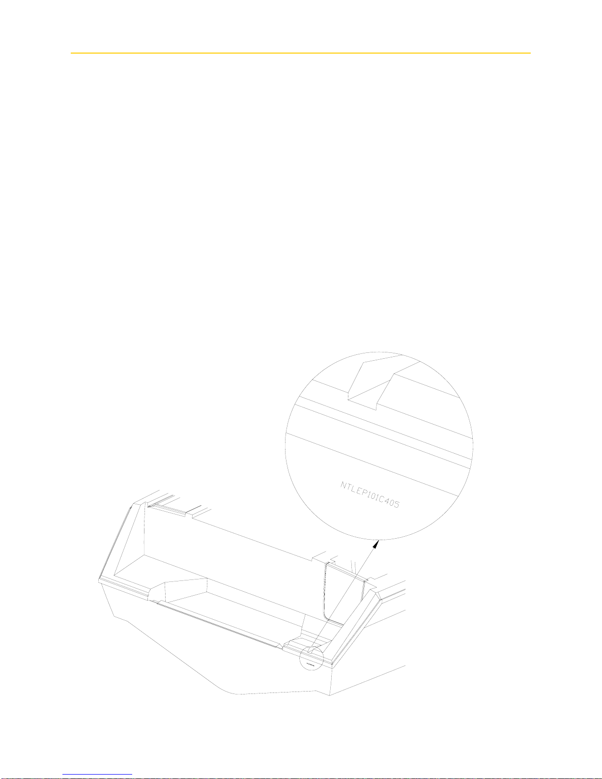
The “Hull Identification Number,” located on the starboard side of the transom, is a
significant source of identification and must be noted in all correspondence and orders. Failure to
include the HIN only creates delay.
1–2
WELCOME
HAZARD WARNING LABELS
The hazard warning labels shown below are applied throughout this manual to alert the
customer of potentially dangerous situations that can lead to death, personal injury, and/or product
damage. We urge you to observe these warnings and comply with all safety recommendations.
D A N G E R
!
This symbol alerts you to imminently hazardous situations which will cause severe personal injury
or death if the warning is ignored.
W A R N I N G
!
This symbol alerts you to potentially hazardous situations or unsafe practices that could result in
severe personal injury or death if the warning is ignored.
C A U T I O N
!
This symbol alerts you to potentially hazardous situations that may result in minor personal
injury or cause product or property damage if the warning is ignored.
N O T I C E
This symbol calls attention to installation, operation, or maintenance information which is
important for proper operation, but is not hazard related.
1–3


SAFETY
Chapter 2: Safety
REQUIRED SAFETY EQUIPMENT
The US Coast Guard (USCG) requires that every boat have specific equipment on board.
Check with local regulations on mandatory equipment apart from the list of Coast Guard
requirements. See Sportfish, Cruisers, Yachts Owner’s Manual page 17 for details on the
following required safety equipment.
•Fire Extinguisher
Boats should be equipped with a marine approved fire extinguisher.
• Personal Flotation
All passengers must have an USCG approved personal flotation device (PFD).
Children and non-swimmers are advised to wear a PFD at all times.
• Sound Signaling Device (Horn, Bell Or Whistle)
Your Grady-White is equipped with a horn that meets USCG requirements.
• Visual Distress Signals
USCG approved visual distress signals are required on U. S. waters. See page 33 of the
pamphlet Sportfish, Cruisers, Yachts Owner’s Manual enclosed with this manual for more
information.
• Lighting
Grady-White boats are equipped with navigational lights that meet requirements for
recreational vessels for inland and international waters.
ADDITIONAL RECOMMENDED EQUIPMENT
In addition to the required safety equipment, there are items that will provide an extra margin
of safety and convenience for you and your passengers while boating. For an extended list of
basic gear, tools and spare parts, reference page 18 of the pamphlet Sportfish, Cruisers, Yachts
Owner’s Manual enclosed with this manual.
Keep tools and spare parts in good condition; replace parts removed from spare parts kit. Most
importantly use US Coast Guard approved or marine certified parts where applicable. Conditions
found requiring corrective action should be worked on by a qualified repairman.
REGISTRATION NUMBERS
Federal and state laws require a powerboat to be registered in the state where it is primarily
used. Registration numbers and validation stickers must be displayed according to regulations.
The registration certificate must be on board when boating. The boat serial number or Hull
Identification Number (HIN, page 1–2) is required on the registration form. The HIN is located
on the upper right hand corner of the transom, and is the most important identifying factor. The
HIN should be included on all documents and any correspondence to provide you timely service.
2–1

S AFETY
EMERGENCY STOP SWITCH
Some Grady-Whites are equipped with an emergency stop switch. This is a safety feature that,
if used properly, will shut the engines down if the operator leaves or falls from the helm position.
This ignition shutdown system includes a shut-off switch, switch clip, lanyard, and lanyard clip.
The lanyard clip should be attached to the operator. If a situation arises where the boat should
stop, a pull on the cord to release the clip from the shut-off switch will shut down the engines.
Simply reinstalling the switch clip will reset the emergency stop switch. The decision to use the
emergency stop switch rests with the owner/operator. See page 72 in Sportfish, Cruisers, Yachts
Owner’s Manual.
EMERGENCY INFORMATION
Unpleasant situations may develop while boating. You should prepare yourself on how to
cope with emergency situations should one materialize aboard your vessel or someone else’s.
Anticipate a game plan for specific situations such as fire, man overboard, collision, etc., to give
you the confidence and ability necessary for an emergency; the key is to remain calm. For
emergency procedures, see Section 4 in Sportfish, Cruisers, Yachts Owner’s Manual.
• Rendering Assistance
The owner or operator of a vessel is required by law to render all practical or necessary
assistance to any person or vessel affected by collision, accident, or casualty. However, you
are not required to endanger your vessel or passengers to render assistance.
• Accident Reporting
Report all boating accidents to your local authorities. Federal regulations require boat
operators involved in an accident to submit a written report within 48 hours. In the event of
death or disappearance, notification is required immediately by phone or radio in addition
to the written report. These reports can be submitted to the State Boating Law Administrator.
Forms can be obtained through the USCG, local harbor patrol offices, sheriff, and police
stations.
• Lightning Precautions
This awareness is included to ensure the safety of the owner and passengers. Always be
mindful of the weather! When a lightning storm advances, certain safety precautions should
be taken. Dock the boat and seek shelter on land. If this is not possible seek refuge inside the
boat until the storm has passed. Stay out of the water! Lightning will seek a ground when it
strikes and may pass through metal components if it hits your boat. For this reason avoid
contact with metal parts of the boat under these conditions.
2–2

SAFETY
BOATING SAFETY TIPS
Safety is an important aspect of boating. Your safety as well as the safety of your passengers
and vessel is your responsibility. The following precautions, and the ones mentioned in section 1
of Sportfish, Cruisers, Yachts Owner’s Manual, will add to yours and your passengers’ boating
safety and pleasure.
• Before operating your Grady-White, READ AND STUDY ALL OPERATION AND
MAINTENANCE MANUALS. It is important that you fully understand how to use your
boat. Contact your Grady-White dealer for questions. Proper use and service will insure quality
performance and longevity of your boat.
• A written float plan left with a RESPONSIBLE person can serve as valuable information
should you not return as scheduled. Upon returning, your primary responsibility is to notify the
person of your return.
• NEVER operate or allow anyone to operate your boat while under the influence of drugs or
alcohol.
• Individuals under the age of 16 should not be allowed to operate your boat.
Inexperienced drivers should have constant and direct supervision.
• Instruct at least one passenger on the fundamentals of basic boating and safe operation in the
event of an emergency.
• While boating, passengers should be settled in a safe position. Use hand holds and rails for
steadiness. Do not allow bow, transom or gunwale riding. Remember, the captain is ultimately
responsible for the safety of the passengers aboard their vessel.
• Keep your boat speed under control. Respect for other boaters and those on shore are common
courtesy. The boat’s operator is responsible for injury or damage caused by the boat or the
wake. Your wake could swamp a smaller craft and endanger its passengers. Stay alert for
posted “No Wake Zones”.
• Become familiar with the handling personality and limitations of your boat.
• Never allow swimmers/skiers to enter or exit the boat with engines running. A shift lever
in neutral could become engaged accidentally. Also, exhaust fumes from the outboard engines
contain carbon monoxide gas. These fumes may concentrate in this area.
• Obtain information and a chart for new areas when possible.
• Clean water and air are responsibilities for all persons. Use litter containers on board and
dispose of refuse properly. See “Pollution Regulations” on page 3–3.
• Know and obey the “Rules of the Road”. See Sportfish, Cruisers, Yachts Owner’s Manual
beginning on page 19 for a better understanding of rights of way, signals, and waterway
markers.
2–3
S AFETY
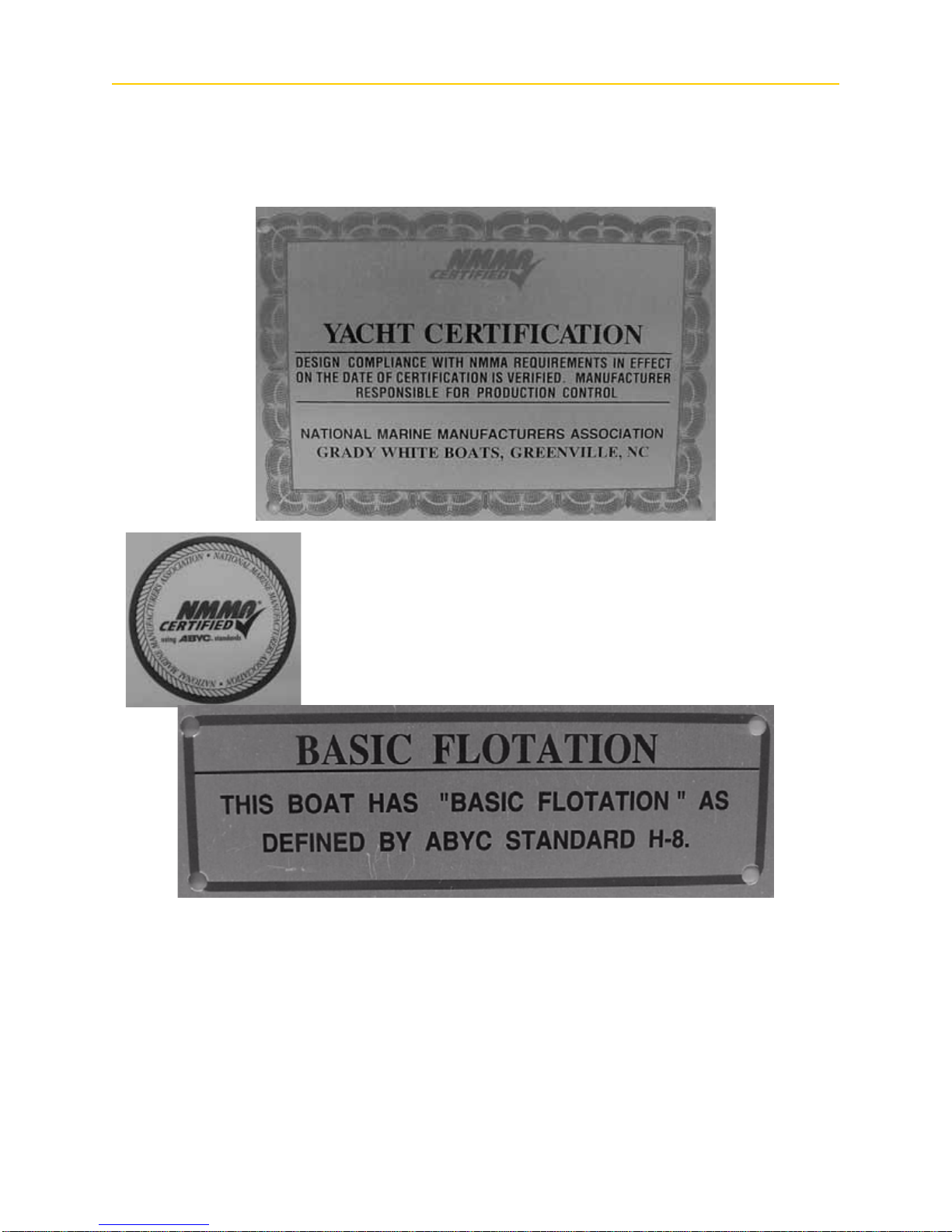
CERTIFICATION
At the helm station you will find a NMMA (National Marine Manufacturers Association)
Yacht Certification tag. This means your yacht complies with the Coast Guard safety standards.
(NOTE: Any boat with an overall length of 26 feet or greater is defined as a “yacht” by NMMA.)
This label means your Grady-White is certified by the NMMA. With
this tag, you are assured your fuel system, electrical system, lighting,
ventilation, and steering are not only in compliance with the US Coast
Guard regulations, but also meet the more stringent standards of the
NMMA. The NMMA is a national trade organization serving all
elements of the recreational boating industry including manufacturers
of boating equipment. With this tag, you can have confidence in the
safety of your boat.
This label means that Grady-White has designed and built your boat to the ABYC basic
flotation standard H-8. Basic flotation is defined as having enough foam in the boat to create
buoyancy and prevent sinking under swamped conditions.
LOADING CAPACITY
Though overloading is a primary cause of many boating accidents, improper loading is
equally hazardous. Boaters should know the amount of weight on board and evenly distribute the
weight within the boat.
2–4

SAFETY
CARBON MONOXIDE
D A N G E R
!
CO is produced by all gasoline engines and generator sets. Keep cockpit and cabin areas well
ventilated and avoid blockage of exhaust outlets. Extended exposure to (CO) can cause brain
damage or death. Signs of exposure include headache, nausea, dizziness, and drowsiness.
Carbon Monoxide, commonly written CO, is a colorless, odorless gas emitted from any boat’ s
exhaust. The gas is similar in weight to the air we breathe. Therefore, it cannot be expected to rise
or fall, but will accumulate in confined spaces.
Carbon monoxide is poisonous and potentially fatal if breathed over an extended period of
time. Symptoms of CO poisoning include: dizziness, nausea, headache, sleepiness, vomiting,
throbbing in the temples, muscular twitching, and an inability to think clearly. If you or anyone
else experience these symptoms, immediately get away from fumes and into an area where
plenty of FRESH air can be consumed. If any symptoms from above persist, seek medical
attention.
Carbon monoxide can accumulate in cabins and under canvas. If your boat is equipped
with a canvas that encloses the aft cockpit and propulsion equipment, do not operate the boat with
this canvas closed.
Operators need to be aware of the influence of other boats on their vessel as well as the effects
they have on neighboring crafts. Of primary concern is the operation of an auxiliary generator
with boats moored along side each other. This situation creates an atmosphere which is filled with
CO, and extremely dangerous.
W A R N I N G
!
BE AWARE of the affect your exhaust may have on other vessels. Likewise, BE AWARE that the
operation of other vessel's equipment may influence the carbon monoxide concentration on your
vessel.
W A R N I N G
!
Exhaust fumes from engines contain CO. Boats with canvas deployed are more likely to collect
exhaust fumes. Keep cockpit and cabin areas well ventilated.
2–5

S AFETY
SUGGESTED BOATING CLASSES AND READING MATERIAL
Like a car, boats must be operated according to safety rules and traffic regulations. Although
we include some basic boating tips in this manual, a thorough review of the safety rules and
regulations for boating is beyond the scope of this text.
We support the work of the United States Coast Guard Auxiliary and the United States Power
Squadrons. We urge you to exercise the opportunity to attend any instructional classes sponsored
by these organizations. Reference page 8 of Sportfish, Cruisers, Yachts Owner’s Manual for
training options and page 23 for information on charts and maps. For further knowledge on
boating, we advise that you review the following publications.
• Piloting, Seamanship and Small Boat Handling
(Chapman)*
Motor Boating and Sailing
Post Office Box 2319 -- F.D.R. Station
New York, New York 10022
*Available on CD ROM
• Pleasure Boating and Seamanship
US Coast Guard Auxiliary
306 Wilson Road Oaklands
Newark, Delaware 19711
• Boatman’s Handbook
by Tom Bottomly
Motor Boating and Sailing
Post Office Box 2319 -- F.D.R. Station
New York, New York 10022
FOR MORE INFORMATION ON BOATING SAFETY COURSES IN YOUR AREA, CALL
• Boating Education Hotline ......................................................1-800-336-BOAT (2628),
• US Coast Guard Boating Hotline ............................................1-800-368-5647, or
• Contact Your Local Coast Guard.
2–6

G ENERAL I NFORMATION
Chapter 3: General Information
FUELING
W A R N I N G
!
Safety during fueling requires CAUTION and COMMON SENSE.
Please study the following precautions carefully. Consult your dealer if you have any
questions. Prior to your initial fill-up, check your engine manual to confirm the type of fuel
specified by the manufacturer . Never use fuels containing alcohol. The alcohol can deteriorate the
rubber materials used to make up your fueling system. Methanol based fuels absorb water making
fuel more corrosive to the metals in tanks and carburetors.
BEFORE FUELING
• Shut down all engines.
• Turn battery select switch(es) to “OFF” to insure that all fans, lights, etc. are off
• Close all ports, hatches, windows, and engine compartments to prevent fumes from
accumulating in closed areas.
• Extinguish cigarettes and all other lighted materials.
• Have a fire extinguisher near.
DURING FUELING
• Observe all safety regulations for the safe handling of fuel.
• Keep the fuel supply nozzle in contact with the fuel tank opening to prevent any static sparks.
AFTER FUELING
• Secure the fuel cap and check fuel lines and connections for leakage. Wash and clean up any
spilled fuel. Dispose of clean up rags or sponges on shore. Do not store these clean up rags in
the boat.
• Ventilate all ports, windows, hatches, and other closed areas. Conduct a “sniff test” to make
certain all fumes are vacant before using the battery select switch(es).
• Select your first tank cautiously. Take into consideration the distribution of your load as fuel is
consumed. Performance will be influenced by weight distribution. If your boat is equipped
with two fuel tanks, use the fuel select valve (see “Fuel Select Valve” on page 3–2) to select
the proper tank.
See warnings and check list in Section 6, page 37 of the Sportfish, Cruisers, and Yachts
Owner’s Manual. Reference the “Fuel Tank Compartment” on page 6–6 for more information on
cleaning the fuel storage area.
FUEL SYSTEM
Inspect the fuel hoses, connections, and tanks for tightness, signs of leaks, and deterioration
after fueling. Annually conduct a more detailed inspection of fuel system components, especially
3–1
G ENERAL INFORMATION
those hidden from routine inspection. Replace deteriorated hoses, clamps, connections, or fittings
immediately.
If you are experiencing fuel flow problems, there is a simple method to determine if the
problem is in your fuel system or your engine. Connect a six-gallon portable tank to your engine.
If the problem persists, the likely cause is with the engine itself. If the problem goes away, the
source must be in the boat fuel system. One component that should be inspected if a restriction
occurs is the anti-siphon valve. If fuel does not flow properly through this part, it must be cleaned
and/or replaced. DO NOT remove the anti-siphon valve and replace with a regular barb.
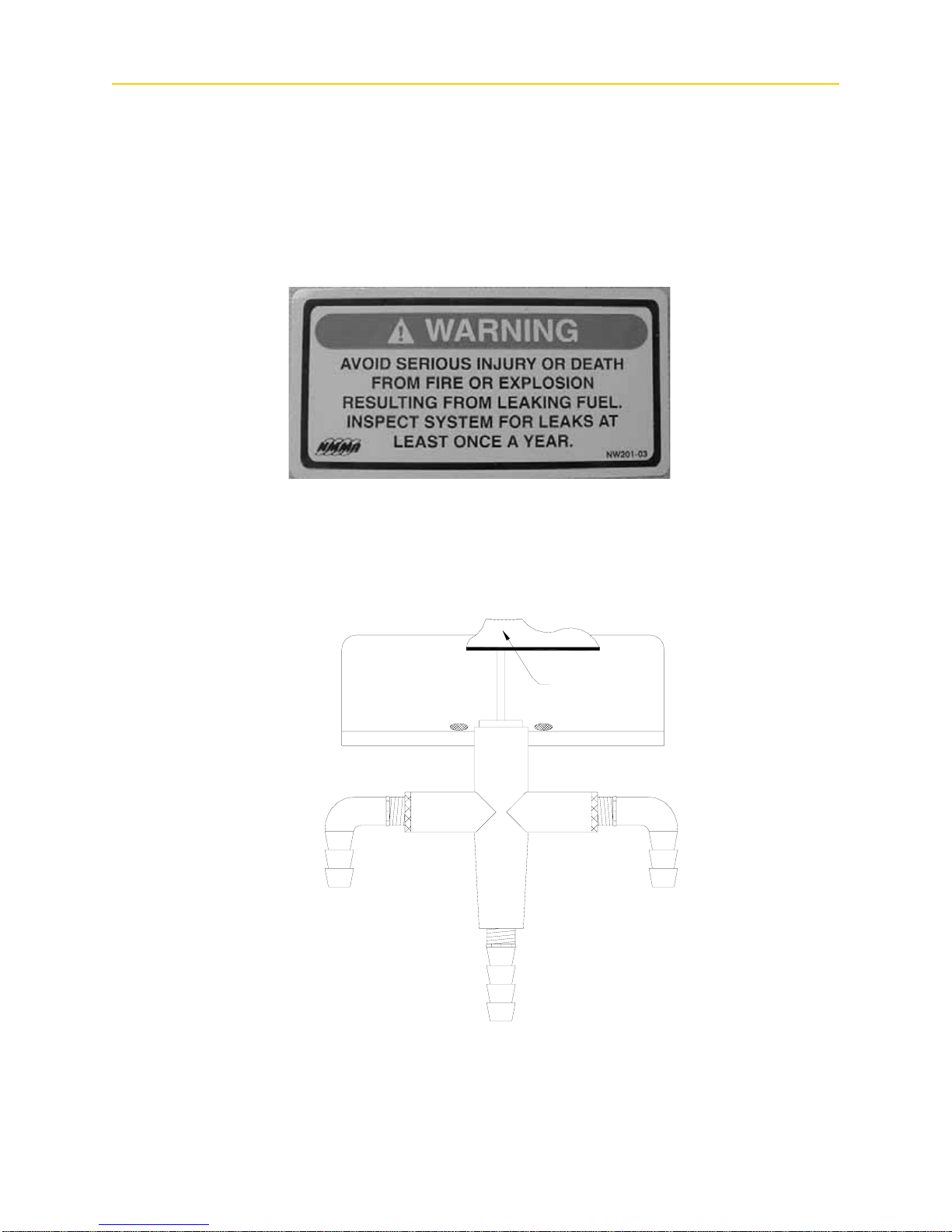
FUEL SELECT VALVE
If your boat is equipped with dual fuel tanks, you will have a manual fuel select valve
installed. This valve allows you to choose from which tank fuel will be consumed. Remember, as
the fuel is consumed and the fuel load redistributes, the performance will be influenced. Select the
tank that allows the best performance for your boat.
Aluminum
Angle
Brass Elbow
1/4" Male X 3/8"
Barb
To Aux
Tank
3-way Shut
Off Valve
To Main
Tank
To
Engine
3–2
G ENERAL I NFORMATION
POLLUTION REGULATIONS
The U.S. Coast Guard defines restrictions on the discharge of oil or hazardous substances and
plastics or garbage in the “Federal Requirements for Boating and Boating safety”. You should
have received this pamphlet when you registered your boat. Detailed below is a summary of those
regulations. You should read the pamphlet and also become familiar with any local restrictions
where you operate your vessel. Passengers or crew members aboard your boat should also be
notified of these regulations.
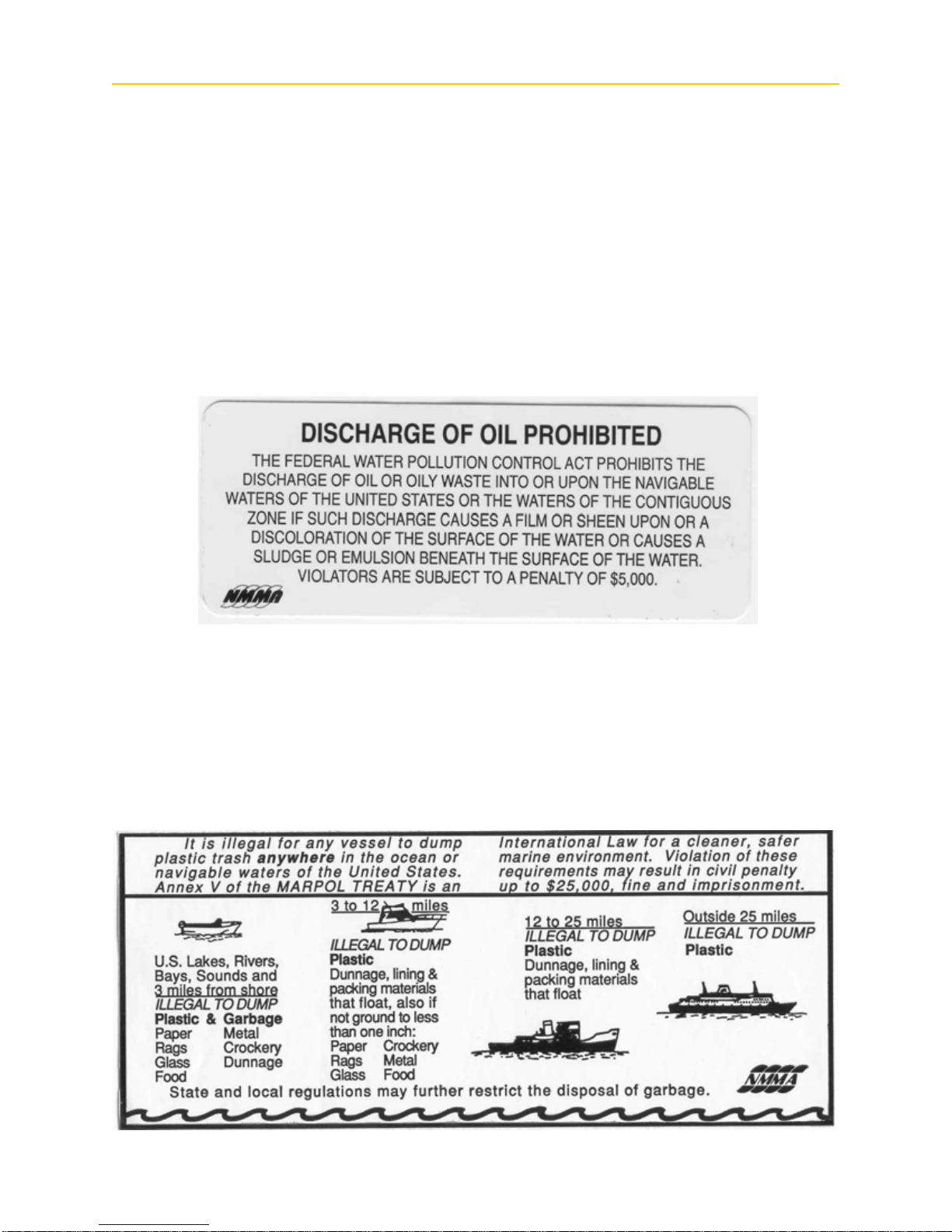
Discharge Of Oil Or Hazardous Substances
The Federal Water Pollution Control Act prohibits the discharge of oil or hazardous
substances which may be harmful into or upon U.S. navigable waters. Vessels 26 feet in
length or over must display a placard at least 5” x 8” in a visible location in the bilge or near
the bilge pump controls. The placard should state the following:
Disposal Of Plastics Or Garbage
The MARPOL ANNEX V is the Act to prevent pollution from ships and other vessels.
Federal regulations prohibit the discharge of plastic garbage anywhere in the marine
environment. Plastic includes but is not limited to: synthetic fishing nets, ropes, lines, straws,
six pack holders, styrofoam cups, lids, bottles, buckets, and plastic bags. These regulations
also restrict the disposal of other types of garbage within specified boundaries from shore. The
following plaque will help you determine the specific distances offshore that certain garbage
is permitted.
3–3

G ENERAL INFORMATION
TRAILERING
The adjustment and balance of your boat on the trailer determines how easily your boat may
be transported. The tongue weight on the hitch ball should be 5-10% of the total weight of your
boat, motor, and trailer. Tail-heavy loads cause swaying while trailering. The rollers and/or
bunkers of your trailer should be adjusted so that the weight is distributed evenly across the stern
and forward throughout the keel sections. Your dealer is capable of adjusting your trailer properly.
Practice maneuvering the trailer; the trailer always backs in the opposite direction of the
vehicle. To maneuver the trailer, turn the steering wheel in the direction you want the trailer to go.
Familiarize yourself with this manual and all aspects of your boat prior to initial launch. At the
launch site, go through a pre-launch checklist. The list should be suited to your specific needs.
Trailering and relative information is provided in the Sportfish, Cruisers, and Yachts Owner’s
Manual in Section 9, page 94.
PREDEPARTURE CHECKLIST
Sportfish, Cruisers, and Yachts Owner’s Manual provides a checklist for predeparture on page
35.
CASTING OFF AND APPROACHING THE DOCK
Unlike an automobile, the stern of your boat reacts first when turning. A turn to the right will
swing the stern to the left and vice-versa. Remember that turning your boat away from an object
such as a dock will tend to swing the stern toward that object. See page 43 in your publication of
Sportfish, Cruisers, and Yachts Owner’s Manual.
TOWING
In the event of a mishap or power loss, you may need to tow a boat or have yours towed.
Remember, you should not tow a boat larger than your own. Never tow a boat if you are not
equipped with the proper lines; nylon ropes are recommended. They have the strength and
elasticity needed to absorb the shock of towing and sudden jerks. Individuals should never hold a
towline — always secure it to the boat.
Before towing a boat, make a bridle and tie it securely to the pad eyes on the transom with
enough slack to clear the engines. Pad the line wherever it comes into contact with the boat to
prevent chafing. Attach a tow line to the bridle so that it can slide from side to side to prevent too
much pressure on a single pad eye. The tow line should then be attached to the bow eye or to a
bridle on the towed boat. The tow line should be a minimum of twice the length of the towing
boat, the longer the better. Do not try to run in too close when passing the towline to the other
boat. Send either a light line or attach the towline to a life preserver to be pulled in. Be aware of
the other boat’s propeller.
The towed boat should always have someone at the wheel since the boat may swing off
course. Start the tow off slowly; a steady pull at a moderate speed should be used. It is important
to keep the slack out of the propeller area. Watch the action of the towing boat. If excessive slack
develops in the towline and contact is obvious, turn in either direction to avoid hitting the stern.
W A R N I N G
!
As a precaution, passengers on both boats should stay clear of the towline. Lines under stress
could snap and fly in either direction causing injury.
3–4

G ENERAL I NFORMATION
SHALLOW WATER
Most boats that become grounded can be floated off with motor(s) tilted to reduce the draft at
the transom. With motors tilted, try rocking the boat from side to side to break the suction of mud
from the keel. Move passengers or heavy objects from the point where the boat is grounded. Do
not lower or start the engines until the boat is clear of the ground. Refer to page 53 in Sportfish,
Cruisers, and Yachts Owner’s Manual.
C A U T I O N
!
Do not lower or start engines if the propeller is in mud or sand. Wait until the boat is refloated to
avoid damage to the cooling system of your engine.
Be mindful of water level fluctuations when boating in water with tidal changes. If you are
grounded on an incoming tide, wait until the tide is high enough to refloat your boat. However, on
an outgoing tide, quick action should be taken to refloat your boat. If this is not possible, set an
anchor to keep the boat from becoming driven further aground; set the anchor to counter the
action of the wind or current. The anchor, in some cases, can also be used to pull the boat free.
Many inland areas have rocks and stumps which could crack or puncture a fiberglass hull. Be
familiar with the boating area, and use caution in shallow water.
ANCHORING
Some factors that determine the size and type of anchor most suitable for your boat include
the size of your boat and the type of lake, sea, or river bottom in your boating area. See page 46 in
Sportfish, Cruisers, and Yachts Owner’s Manual for more information on anchoring.
N O T I C E
It is illegal to tie your boat to navigational aids such as buoys and markers.
W A R N I N G
!
Never anchor off the stern of the boat especially in strong winds or currents. The weight of the
stern and flat surface to the seas can easily cause water to enter over the transom and swamp the
boat.
WINDLASS
Anchoring can be less laborious if your boat has a windlass accessory . If your boat is equipped
with a windlass, reference your windlass Operation Manual for instructions.
3–5

G ENERAL INFORMATION
GENERAL INFORMATION ON BOAT HANDLING
The best method of learning how to handle and obtain the best performance from your boat is
to practice and experiment. After several hours of operation, you should experiment with the
throttle settings to discover the setting that will be the most comfortable and economical range for
your particular loading conditions.
We suggest you make a speed/RPM chart in order to obtain the most economical operation.
Operate the boat at various speeds while monitoring the fuel consumption. Determine the amount
of operating time remaining when the fuel gauge has only one bar remaining on the display. Make
a log of this type of information, and have it available when using your boat. Other statistics you
may want to determine could include the following:
• Minimum speed for effective steering.
• Turning radius at different speeds.
• Response to steering at low speeds.
• Acceleration and deceleration rates.
• Time and distance to bring the boat to a stop at different speeds.
• Control of the boat using both engines in close quarters.
Also, read the section in Sportfish, Cruisers, Yachts Owner’s Manual beginning on page 49 for
information on safe operating speed.
TWIN ENGINE BOATS
T win engine boats are easy to ma neuver. The boat will run ahead or backward in a straight line
when both engines are working together at the same speed. The engines also can be used to steer
to port as well as starboard. Moving ahead on one engine will cause the bow to swing away from
the running engine side and move forward at the same time. Backing up with one engine will
cause the bow to swing toward the running engine side and the boat to move backward. Running
one engine ahead and one engine astern will cause the boat to turn end-for-end in little more than
its own length. Running both engines in the same direction at different speeds will cause the boat
to move in the direction dictated by the faster engine, but its influence will be modified by the
slower engine.
3–6
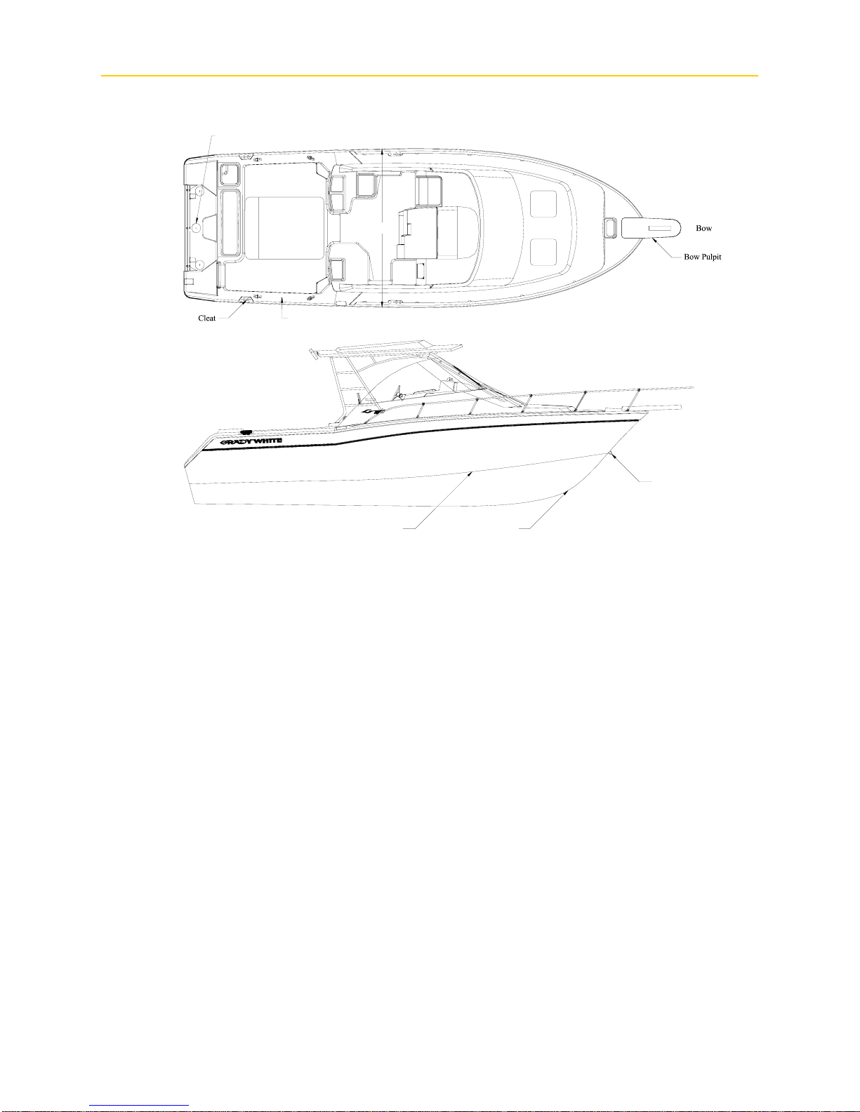
COMMONLY USED NAUTICAL TER MS
G ENERAL I NFORMATION
Access Plate
Stern
Gunwale
Abeam - a line perpendicular to a
boat’s keel
Access Plate - a removable,
watertight cover that provides quick
entry to enclosed areas for
maintenance or visual inspection.
Aft - toward the rear or stern of the
boat
Beam - the greatest width of the
boat
Bilge - the lower interior area of the
hull
Bow - the forward section of the
boat
Bow Eye - a U-shaped hull fitting
used to attach the trailer winch to
the boat
Port Side
Beam
Starboard Side
KeelChine
Draft - depth of water required to
float a boat
Fathom - a depth measurement
equal to six feet
Freeboard - distance measured
between waterline and deck
Gunwale (Gunnel) - point where
the deck and hull join
Hatch - an opening in the deck to
provide access below
Headroom - vertical distance
between the floor and over head
structure or canopy ceiling
Hull - major component that
provides a watertight platform
buoyant enough to float a craft and
its load
Bow Eye
Port - a term designating the left
side of the boat when facing
forward
Scupper - holes permitting water to
drain overboard from deck and
cockpit
Sheer - curve or sweep of the deck
as viewed from the side
Starboard - a term designating the
right side of the boat when facing
forward
Stern - rear of the boat
Stringer - longitudinal members
fastened inside the hull to add
rigidity and strength
Wake - the movement of water
created by a moving boat
Bulkhead - vertical partition in the
boat
Chine - point where the topside and
bottom of the boat join
Cleat - deck fitting with arms or
horns on which lines are fastened
Deck - upper structure which
covers the hull
Keel - the major longitudinal
member of a hull -the lowest
external portion of the boat
Knot - a measurement of speed
equal to nautical miles per hour
Lee - the side that is sheltered from
the wind
List - a tilt or lean to one side
3–7
Windward - side facing the
direction of the wind (against the
wind)


PERFORMANCE
Chapter 4: Performance
PERFORMANCE FACTORS
Maximum performance is dependent on many factors and cannot be guaranteed. These factors
will vary with changing conditions. Some of these factors are listed below. Reference the trouble
shooting guide, page 65 in Sportfish, Cruisers, Yachts Owner’s Manual, for additional suggestions
on adjusting performance.
Engine Efficiency
Engines operate most efficiently at the RPM confirmed in the engine operating manuals,
assuming your boat is equipped with the correct engine(s), the engine(s) are properly tuned,
and the drive system(s) are in good condition. Efficiency will decrease if normal care and
maintenance is not performed. Neglecting the engines will cause power to drop and speed to
decrease. In addition, expensive repairs may become necessary. Be sure to follow all
instructions in the engine operation manual(s).
Weather Conditions
Weather conditions affect engine performance. Barometric pressure and humidity both
influence horsepower. A change of weather could cause a 10% loss in horse power on some
hot days.
Load Distribution
A decrease in performance will be noted when gear, equipment, passengers, and fuel are
added. This type of extra load will affect the performance of the boat according to the
distribution of the weight. Water accumulation in the bilge, another type of extra load, will
affect performance. Keep the bilge dry to eliminate this problem.
Marine Growth
Maximum performance is obtained only when your hull bottom is clean. Marine growth on
the bottom of the boat will increase resistance and decrease speed. These conditions will also
increase fuel consumption. Reference “Cleaning” on page 6–1 for more information on
cleaning your hull bottom.
Trim
Most outboard models are equipped with power tilt and trim mechanisms. The purpose of
power tilt is to raise the engine for launching, loading, or trailering your boat. Power trim may
be used to adjust the boats planing performance and running attitude. See Power trim in
Sportfish, Cruisers, Yachts Owner’s Manual on pages 52 and 72.
Trim refers both to the weight distributions inside the boat and to the angle of thrust of the
drive unit. The angle of thrust of the drive unit forces the bow up or down. The trim tabs on
your boat also control the trim of the boat, similar to the power trim. Refer to the Trim Tabs
section in Chapter 8 for additional information.
4–1
P ERFORMANCE
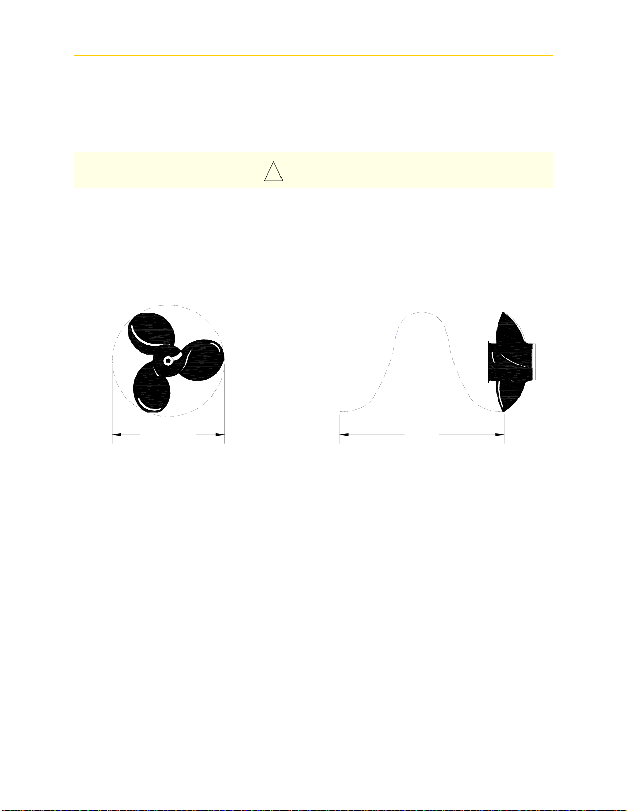
Propeller
The condition of your prop has a major influence on the performance of your boat. Your
engine(s) should be equipped with the best size prop for normal conditions. Unusual uses or
weight conditions may require special props. A damaged prop can affect your boat's top
speed, cause vibrations, create a sudden drop in RPMs, or even increase fuel consumption.
C A U T I O N
!
Stay within the engine manufacturer's maximum and minimum RPM ranges when replacing
props. This information is located in your engine manual. If your boat does not have a tachometer ,
consult your dealer for propeller changes.
PitchDiameter
Diameter = 14 Pitch = 14
Diameter and pitch are the two basic dimensions of a propeller. Diameter is the distance
across the circle made by the blade tips as the propeller rotates. Pitch is the theoretical (not
accounting for slippage) forward distance the propeller would move in one revolution. An
example of a propeller dimension would be 14 X 17 for a propeller having a diameter of 14”
and a pitch of 17”.
4–2
PERFORMANCE
PROPULSION SYSTEM – OUTBOARD
The engine manufacturer supplies all vital information concerning your engine(s) in the
Operation and Maintenance Manual(s). Details of important engine functions such as the
lubrication system, cooling system and alarm/monitoring system are outlined in these manuals.
Your familiarization with this engine reference material will result in the proper usage and service
essential for safe and enduring engine performance. These manuals are included with the Owner’s
Packet.
D A N G E R
!
Do not inhale exhaust fumes! Exhaust contains carbon monoxide — a dangerous gas which is
potentially lethal.
W A R N I N G
!
Do not attempt to service any engine or drive component without being totally familiar with the
safe and proper service procedures. Certain moving parts are exposed and can be dangerous.
C A U T I O N
!
Do not paint the outboard motors with anti-fouling paints designed for boat hulls. Many of these
paints can cause severe damage to the engines.
ENGINE WARRANTY
A warranty registration card is included with all engine manuals and should be completed and
returned to the engine manufacturer as soon as possible.
4–3

P ERFORMANCE
STEERING
Most outboard engines are equipped with an adjustable rudder trim tab. This trim tab should
be adjusted to balance the steering at the speed which you travel most frequently. Variations in
speed, boat load or engine trim will cause the steering to pull in one direction. If the boat pulls to
the left, adjust the trim tab to the left and vice-versa.
• Hydraulic Steering
Hydraulic steering systems (not to be confused with power steering) require regular
preventative maintenance for continued safe and reliable operation. The oil level in the helm
pump must be maintained within acceptable operating levels. A low oil level will cause air to
be introduced into the steering system resulting in unresponsive steering. The oil level should
always be within one-half inch from the base of the fill hole located on the front top portion of
the helm pump. Check the entire steering system regularly for oil leaks; unobserved leaks over
a period of time will result in unresponsive steering or loss of steering.
Any moving mechanical linkages, sliders, etc. should be greased as needed with a high quality
marine grease. Refer to the manufacturer’s steering manual for specific recommendations and
additional maintenance.
Any slow or sudden change in the “feel” of your steering system indicates an immediate need
for a thorough inspection. All repairs and replacements to steering systems should be made by
an authorized repairman.
• Power Assist Hydraulic Steering
The engine ignition switches must be on for this system to function. The power assist
hydraulic pump in activated simply by turning the steering wheel. The hydraulic pump senses
the motion of the hydraulic fluid from the helm and pumps fluid in the cylinders at the engine
accordingly . The power assist pump is installed in the starboard aft berth rigging compartment
and can be accessed via the access panel in the aft berth wall. The power source for this pump
is the bow thruster battery located behind the helm table. Over-current protection is provided
by a 40A fuse located near the bow thruster battery. This system is compatible with multiple
steering stations and the use of an autopilot. Refer to the owner’s manual in your owner’s
packet for more information.
• Tilt Steering
This feature enables the operator to tilt the wheel up or down. Refer to the steering system’s
owner's manual for information on oil levels with tilt steering.
4–4
 Loading...