

Page 1

UAM VENTILATOR
QUICK SET UP GUIDE
Page 2
1
Page 3
Setting Up the Ventilator
preparing the UaM and the Ventilator
1. Ensure that equipment such as the ventilator and the patient monitor are
securely attached to the top shelf of the UAM
2. Ensure that all cables and sample lines are correctly attached – refer to the
manual of each individual manufacturer.
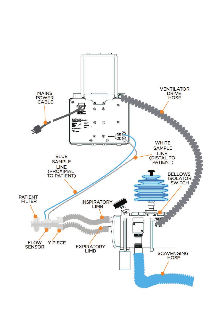
3. Connect these essential items:
a. Patient Circuit with Y piece.
b. Ventilator to UAM using the ventilator drive hose.
c. Ventilator patient flow sensor between the patient Y piece and the
bacteria filter.
d. Ventilator patient flow sensor sample lines at rear of ventilator
e. Patient bacterial filter to prevent flow sensor contamination
f. Theatre anaesthetic gas scavenging system
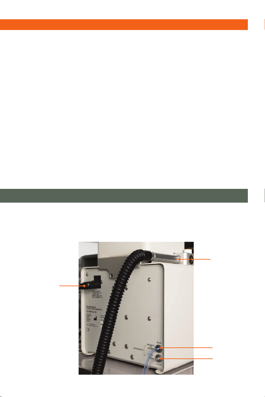
Ventilator ConneCtionS
1. Flow sensor connection – The patient inspired and expired
gas is measured with a variable orifice flow sensor.
a. Distal to patient – The clear tube is connected furthest from the patient.
b. Proximal to patient – blue tube. The blue tube is connected closest to
the patient.
note: A breathing circuit filter must be used to prevent contamination.
2. Bellows connection – 17 mm male taper that is attached to the UAM
anaesthesia machine using a 15 mm x 1.5 m black corrugated breathing hose.
3. Mains power inlet socket-IEC power cable.
3
4
2
1
2
Page 4
perforMing the pre-USe CheCkS
1. Check the ventilator for labeling to indicate if the machine has any faults or
needs to be serviced
2. Check for visible signs of damage.
3. Check the correct connection of the patient circuit and any auxiliary
equipment such as patient monitoring equipment, gas scavenger etc.
4. Perform a patient circuit leak check:
a. With the patient circuit connected check that all connections are secure
and all tubes used are in good condition.
b. With the UAM anaesthesia machine in manual bellows mode block
the patient Y piece and ensure that the manual bellows on the UAM
anaesthesia machine can generate 30 cmH2O or more pressure when the
bellows is pushed down without the bellows descending due to a leak.
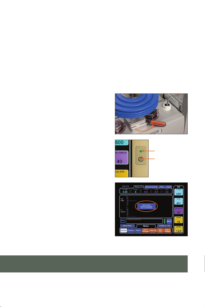
iSolating the hand BellowS
Push the lever to the rear to isolate the
hand bellows and pull it forward when
the hand bellows is in use.
The Manual Bellows Isolator lever isolates
the Hand bellows from the breathing
circuit when the ventilator is being used.
MAINS INDICATOR
Yellow: Mains applied
tUrning the Ventilator on
To turn the ventilator on press the
Green: Ventilator ON
ON/OFF
push button
On/O push button for 1 second.
Start Up Self teSt
If the patient circuit was connected
to a patient or a test lung, the ventilator
will alert you to remove the Y piece and
press to repeat tests.
When the ventilator turns on it will
perform a series of self-tests and the
bellows will move up and down. The
screen will be blank at this time.
note: During these tests, the breathing circuit must be disconnected from
the patient.
3
Page 5
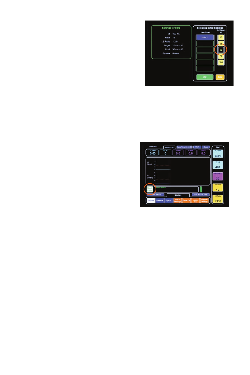
patient SeleCt SCreen
Once the self-tests are over the patient
select screen will appear.
The patient select screen allows the user to
choose patient ventilator settings by weight
– 3kg, 10kg, 25kg, 50kg, 70kg and 100kg or
by selecting one of 6 user-defined settings.
Connect, pulse oximeter probe, NIBP cu
and ECG leads for patient monitoring.
Patient select screen with body weight
setting for 50Kg selected. Note that the
selected key is now black and that the
ventilator settings for this weight are
displayed on the left hand side
Starting the Ventilator
Observe that no alarms are indicated in the
alarms dialogue box – this indicates that
there are no system errors, including mains
power, battery failures. The alarms are
disabled until the ventilator is switched to
the “start” screen allowing the ventilator to
be turned on without nuisance alarms.
Once the user has chosen the initial settings
the actual settings can be adjusted as
required prior to starting to ventilate. If
the settings are to the users satisfaction,
pressing the green “Start Case” button
shown on the lower left hand side of the
display will start the ventilator.
Patient settings are displayed in the “SET”
column on the right hand side vertical
column. These settings can be adjusted
before or during a case. All functions
require “OK” to be pressed to confirm the
setting change. If the setting change is
made and the OK button is not pressed
the screen will time out and stay at the
original setting.
4
Page 6

adJUSting patient SettingS
Patient settings are displayed in the “SET” column on the right hand side
vertical column. These settings can be adjusted before or during a case. All
functions require “OK” to be pressed to confirm the setting change. If the
setting change is made and the OK button is not pressed he screen will time
out and stay at the original setting.
MinUte VolUMe
Minute volume is adjustable between 0.6
and 12 liters per minute.
Press the Vm L/min key to open the
keypad. Either toggle the set value up
or down with the (+) or (-) keys or type
in the new value then press “OK” to
confirm and then “EXIT” or wait for
the key pad to time out
note: The cancel key can be used to return the setting to its original value.
tidal VolUMe
Tidal volume is adjustable between 50
and 1000 ml. Press the VT ml key to
call out the keypad.
Either toggle the set value up or down
with the (+) or (-) keys or type in the
new value then press “OK” to confirm
and then “EXIT” or wait for the key
pad to time out.
note: The cancel key can be used to return the setting to its original value.
preSSUre liMit
Pressure Limit is adjustable between
10 and 50 cmH20.
Target Pressure is adjustable between
10 and 30 cmH20.
Both “Limit” and “Target” pressures
are adjustable. The displayed key in
the Set column is dependent on
whether the ventilator is in Volume
or Pressure mode.
5
Page 7

The call out keypad defaults to the relevant alarm level type for the mode
that has been selected.
The Target Pressure alarm is relevant only to pressure mode and the Pressure
Limit only to volume mode. Note that the pressure limit is automatically
adjusted to 10 Cm H2O above peak pressure during ventilation after 3 breaths
to maintain patient safety.
Press the Plim cmH20 or the Ptarg cmH2O key to call out the keypad.
Either toggle the set value up or down with the + or - keys or type in the new
value then press OK to confirm and then EXIT or wait for the key pad to time
out.
note: The cancel key can be used to return the setting to its original value.
BreathS per MinUte (BpM)
The Breaths per minute, or respiratory
rate, can be adjusted between 4 and
40 breaths per minute.
Press the “Rate BPM” key to call out
the keypad. Either toggle the set value
up or down with the (+) or (-) keys or
type in the new value then press “OK”
to confirm and then “EXIT” or wait
for the key pad to time out.
note: The cancel key can be used to return the setting to its original value.
i:e ratio
The I:E ratio can be adjusted between
1:1 to 1:3 and any value in between.
Press the “I:E Ratio” key to call out the
keypad. Either toggle the set value up
or down with the (+) or (-) keys, type
in the new value or choose a preset
value displayed on the top row, then
press “OK” to confirm and then “EXIT”
or wait for the key pad to time out.
note: The cancel key can be used to return the setting to its original value.
6
Page 8

SeleCting Ventilator ModeS
The following ventilation modes are available:
• Volume Controlled Ventilation (VCV) - delivery of the set tidal or minute
volume at a flow determined by the set inspiration time. If the set volume is
reached early or the set pressure limit is exceeded then the inspiration phase
will end at that time.
• Pressure Controlled Ventilation (PCV) - set target pressure is achieved as
quickly as possible during inspiration. The set target pressure is maintained
for the remaining inspiration time.
• Spontaneous - patient breathes with no assistance from the ventilator. The
ventilator provides measurement of volume, peak, and mean airway pressure.
An apnea alarm will sound if the patient stops breathing.
These modes are accessed through the horizontal line of select buttons at the
bottom of the screen and are color-coded blue.
VolUMe Mode
Press the “Volume” mode key to select
volume mode.
preSSUre Mode
Press the “Pressure” mode key to select
pressure mode.
SpontaneoUS Mode
Press the “Spont” mode key to select
Spontaneous mode. All mechanical
ventilation by the ventilator’s bellows
will cease. Only select this mode if the
patient can breathe unaided.
7
Page 9

Changing Ventilation Mode when
Ventilator iS CyCling
The ventilation mode can be changed
while the patient is being ventilated
without stopping ventilation.
A change of mode must always be
confirmed to prevent accidental mode
change during a case.
Press the key for the new mode
required, eg. If changing from volume
to pressure. The new mode turns white
and a white “Change Mode” key appears.
Press the “Change Mode” key.
A confirmation window appears.
Press “OK” to confirm change to
pressure mode.
Setting the VolUMe alarM and
the apnea tiMe
The volume alarm can be set so that the
alarm is triggered by a measured value
of either Minute Volume or Tidal Volume
outside the set limits. Select the desired
alarm format and press “EXIT” or wait
for the keypad to time out.
The apnea time can be adjusted between
1 and 20 seconds by using the keypad.
Then press “OK” to confirm and then
“EXIT” or wait for the keypad to time out.
In the screen pictured the Tidal Volume
alarm is selected, the Low Airway Pressure
alarm is o and the apnea alarm is set
to 8 seconds. Keys for the selections made
turn white.
8
Page 10

Setting the SCreen waVeforMS
The top screen wave form can be changed to:
a) Flow vs. Time
b) Volume vs. Time
c) Volume vs. Pressure
d) Flow vs. Pressure
Press the Waveform key followed by the
key for the type of waveform you wish to
use as the top waveform.
note: The lower waveform is always
pressure vs. time.
Stopping the Ventilator
At the end of a procedure pressing the
white/red “End Case” button shown
on the lower left hand side stops the
ventilator. This must be confirmed by
pressing the “OK” button on the
“End Case” dialogue box.
tUrning the Ventilator off
To turn the ventilator o, the button must be pressed for 2 seconds, and then
the user must confirm that the ventilator is required to be shut down before a
shutdown sequence will be initiated. If the user does not confirm the requirement
to shut down the ventilator will not enter the shutdown sequence.
Cleaning the Ventilator
The external surfaces of the ventilator can be wiped with a damp cloth followed
by drying o prior to clinical use.
note: mild antiseptic solutions may be used to clean the ventilator but
must be wiped o thoroughly with water on a damp cloth prior to drying.
Care must be taken to prevent water entering the machine during cleaning.
9
Page 11

Cleaning the flow SenSor
The patient flow sensor cannot be autoclaved and should be used with a patient
filter to prevent cross contamination. The flow sensor can be given a wash with
a mild disinfectant and warm water only. After cleaning and air drying it must be
recalibrated.
note: Cleaning with alcohol-based solutions will damage the flow sensor and
result in unreliable flow measurement readings.
note: ensure that the sample tubes are clear of water.
10
Page 12

CaliBrating the patient flow SenSor
note: The patient flow sensor requires calibration when being used for the
first time, periodically once a week, if damage is suspected, and if set
volumes and pressures dier from the screen readings.
1. Disconnect the ventilator drive hose
from the ventilator and attach the
red plastic adaptor to the 17mm
bellows drive taper on the rear
of the ventilator bellows assembly.
2. Connect the patient flow sensor with
the flow in the patient direction
(blue line closest to patient, clear
line closest to ventilator) to first
calibrate in the forward direction.
3. Press the “Flow Cal” button. Then
press “Calibrate Patient Flow”.
Press “yes” to start calibration of
the inspired flow.
4. When prompted, turn the flow
sensor around to calibrate the
expired flow and press the
“continue” button.
5. When complete press exit.
note: The ventilator will prompt the
user to put the sensor in the correct
orientation if connected incorrectly
6. After calibration reconnect the
flow sensor to the patient circuit
Y piece and place a clean patient
bacterial filter ready for the next
case. Reconnect the ventilator drive
hose between the bellows 17 mm
taper and the UAM anaesthesia
machine ventilator connector.
11
Page 13

noteS
12
Page 14

Gradian Health Systems, Inc.
915 Broadway
Suite 1001
New York, NY 10010
T +1 212 537 0340 F 212 954 5299
info@gradianhealth.org
gradianhealth.org
@GradianHealth
 Loading...