

Page 1
INSTRUCTIONS-PARTS
LIST
308–551
This
manual contains important
warnings and information.
READ AND KEEP FOR REFERENCE.
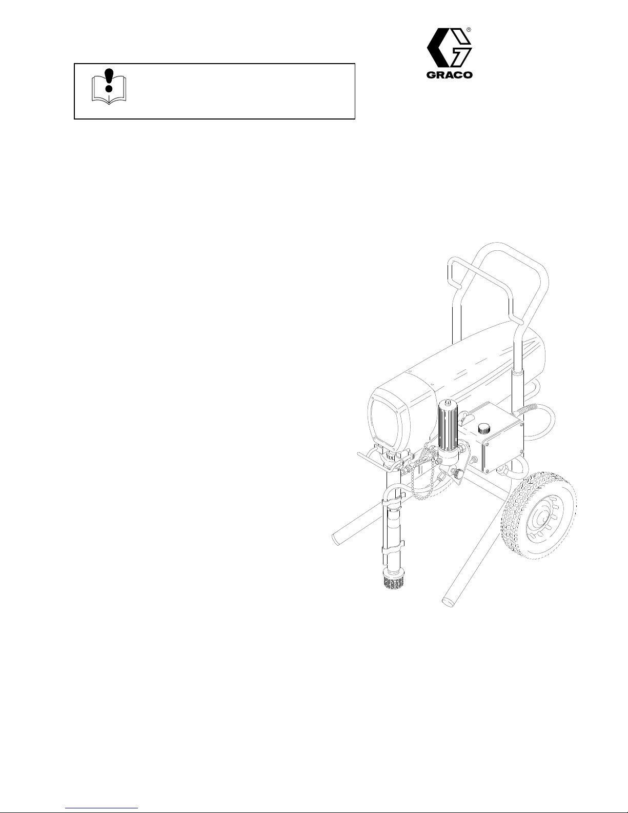
INSTRUCTIONS
120 V
ULTRA
AC, 18A
Plus
+ 1500
Airless Paint Sprayer
3000 psi (21.0 MPa, 210 bar) Maximum Working Pressure
Part No. 223–773, Series A
Basic
Sprayer on upright cart, CSA certified
Patents
Pending
First
choice when
quality counts.
Rev. G
Supersedes D
and PCN E
GRACO INC. P.O. BOX 1441
MINNEAPOLIS, MN
http://www.graco.com
COPYRIGHT
Graco
Inc. is registered to I.S. EN ISO 9001
1994, GRACO INC.
55440–1441
Page 2
Table
of Contents
Warnings 2.
Setup 6
Operation
Flushing 9
Troubleshooting 10
Motor
Displacement
Pressure
Power
Motor 19
. . . . . . . . . . . . . . . . . . . . . . . . . . . . . . . . . . . . .
. . . . . . . . . . . . . . . . . . . . . . . . . . . . . . . . . . . . . . . . .
7. . . . . . . . . . . . . . . . . . . . . . . . . . . . . . . . . . . . .
. . . . . . . . . . . . . . . . . . . . . . . . . . . . . . . . . . . . . .
. . . . . . . . . . . . . . . . . . . . . . . . . . . . . . .
Brush
Supply Cord
. . . . . . . . . . . . . . . . . . . . . . . . . . . . . . . . . . . . . . . .
. . . . . . . . . . . . . . . . . . . . . . . . . . . . . . . . .
Pump
Control
. . . . . . . . . . . . . . . . . . . . . . . . . .
. . . . . . . . . . . . . . . . . . . . . . . . . . . . .
. . . . . . . . . . . . . . . . . . . . . . . . . . .
12.
13.
18.
18.
Symbols
Warning Symbol
WARNING
his
symbol alerts you to the possibility of serious
injury or death if you do not follow the instructions.
Bearing
Drive
Sprayer
Sprayer
Displacement
Accessories 25
Technical
Dimensions 27
Graco Warranty 28.
Phone
Housing & Connecting Rod
Housing
Parts Drawing
Parts List
Data
Number
. . . . . . . . . . . . . . . . . . . . . . . . . . . . . . .
. . . . . . . . . . . . . . . . . . . . . . . .
. . . . . . . . . . . . . . . . . . . . . . . . . . . .
Pump Parts Drawing and List
. . . . . . . . . . . . . . . . . . . . . . . . . . . . . . . . . .
. . . . . . . . . . . . . . . . . . . . . . . . . . . . . . .
. . . . . . . . . . . . . . . . . . . . . . . . . . . . . . . . . . .
. . . . . . . . . . . . . . . . . . . . . . . . . . . . . .
. . . . . . . . . . . . . . . . . . . . . . . . . . . . . . .
. . . . . . . . . . . .
. . . . .
20.
21.
22.
23.
24.
27.
28.
Caution Symbol
CAUTION
This
symbol alerts you to the possibility of damage to
or destruction of equipment if you do not follow the
instructions.
INSTRUCTIONS
WARNING
WARNING
EQUIPMENT MISUSE HAZARD
Equipment
This equipment is for professional use only
Read all instruction manuals, tags, and labels before operating the equipment.
Use the equipment only for its intended purpose. If you are not sure, call Graco T
tance at 1–800–543–0339.
Do not alter or modify this equipment.
Check equipment daily
Do not exceed the maximum working pressure of the lowest rated system component. Refer to
the Technical Data
Use fluids and solvents which are compatible with the equipment wetted parts. Refer to the
nical Data
ings.
Do not use hoses to pull equipment.
misuse can cause the equipment to rupture or malfunction and result in serious injury
.
echnical Assis
. Repair or replace worn or damaged parts immediately
on page 27 for the maximum working pressure of this equipment.
section of all equipment manuals. Read the fluid and solvent manufacturer’s warn
.
.
-
Tech-
-
Route hoses away from traffic areas, sharp edges, moving parts, and hot surfaces. Do not ex
pose Graco hoses to temperatures above 82C (180F) or below –40C (–40
Do not lift pressurized equipment.
Comply with all applicable local, state, and national fire, electrical, and safety regulations.
-
F).
Page 3
WARNING
WARNING
INJECTION HAZARD
Spray
from the gun, leaks or ruptured components can inject fluid into your body and cause ex
tremely serious injury
can also cause serious injury
Fluid injected into the skin is a serious injury
injury
. Get immediate medical attention.
Do not point the gun at anyone or at any part of the body
Do not put your hand or fingers over the spray tip.
Do not stop or deflect leaks with your hand, body
Do not “blow back” fluid; this is not an air spray system.
Always have the tip guard and the trigger guard on the gun when spraying.
Check the gun dif
Be sure the gun trigger safety operates before spraying.
Lock the gun trigger safety when you stop spraying.
, including the need for amputation. Fluid splashed in the eyes or on the skin
.
. The injury may look like just a cut, but it is a serious
.
, glove or rag.
fuser operation weekly
. Refer to the gun manual.
-
Follow the
checking or servicing the equipment.
T
ighten all fluid connections before operating the equipment.
Check the hoses, tubes, and couplings daily
not repair high pressure couplings; you must replace the entire hose.
Fluid hoses must have spring guards on both ends, to help protect them from rupture caused by
kinks or bends near the couplings.
Pressure Relief Procedure
on page 10 if the spray tip clogs and before cleaning,
. Replace worn or damaged parts immediately
TOXIC FLUID HAZARD
Hazardous
skin, inhaled, or swallowed.
Know the specific hazards of the fluid you are using.
Store hazardous fluid in an approved container
state and national guidelines.
Always wear protective eyewear
and solvent manufacturer
fluid or toxic fumes can cause serious injury or death if splashed in the eyes or on the
. Dispose of hazardous fluid according to all local,
, gloves, clothing and respirator as recommended by the fluid
.
. Do
Page 4
WARNING
WARNING
FIRE AND EXPLOSION HAZARD
Improper
result in a fire or explosion and serious injury
grounding, poor ventilation, open flames or sparks can cause a hazardous condition and
.
If there is any static sparking or you feel an electric shock while using this equipment,
spraying immediately. Do not use the equipment until you identify and correct the problem.
Provide fresh air ventilation to avoid the buildup of flammable fumes from solvents or the fluid
being sprayed.
Keep the spray area free of debris, including solvent, rags, and gasoline.
Electrically disconnect all equipment in the spray area.
Extinguish all open flames or pilot lights in the spray area.
Do not smoke in the spray area.
Do not turn on or of
Do not operate a gasoline engine in the spray area.
f any light switch in the spray area while operating or if fumes are present.
MOVING PARTS HAZARD
Moving
parts can pinch or amputate your fingers.
stop
Keep clear of all moving parts when starting or operating the pump.
Before servicing the equipment, follow the
NOTE: This
your sprayer
equipment from starting unexpectedly
is an example of the DANGER label on
. This label is available in other
.
languages, free of charge. See page 25 to order
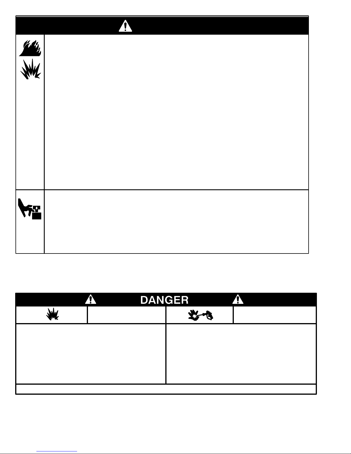
FIRE
AND
EXPLOSION HAZARD
Spray
painting,
in confined areas can result in fire or explosion.
uids
Use outdoors or in extremely well ventilated areas. Ground equip
hoses, containers and objects being sprayed.
ment,
Avoid
all ignition sources such as
cloths,
open flames
arcs from
rettes,
light switches on and off.
ing
Failure
to follow this warning can result in death or serious injury
flushing or cleaning equipment with flammable liq
static electricity from plastic drop
such as pilot lights, hot objects such as ciga
connecting or disconnecting power cords or turn
READ AND UNDERSTAND ALL LABELS AND INSTRUCTION MANUALS BEFORE USE
Pressure Relief Procedure
on page 10 to prevent the
.
SKIN INJECTION
HAZARD
Liquids
-
-
-
-
.
can be injected into the body by high
or
leaks – especially hose leaks.
Keep
body clear of the nozzle. Never stop leaks with any part of the
body.
Drain all pressure before removing parts.A
of gun by always setting safety latch when not spraying.
gering
Never spray without a tip guard.
In case of accidental skin injection, seek immediate
“Surgical
Failure to follow this warning can result in amputation or serious
injury.
T
reatment”.
pressure airless spray
void accidental trig
-
4 308-551
Page 5
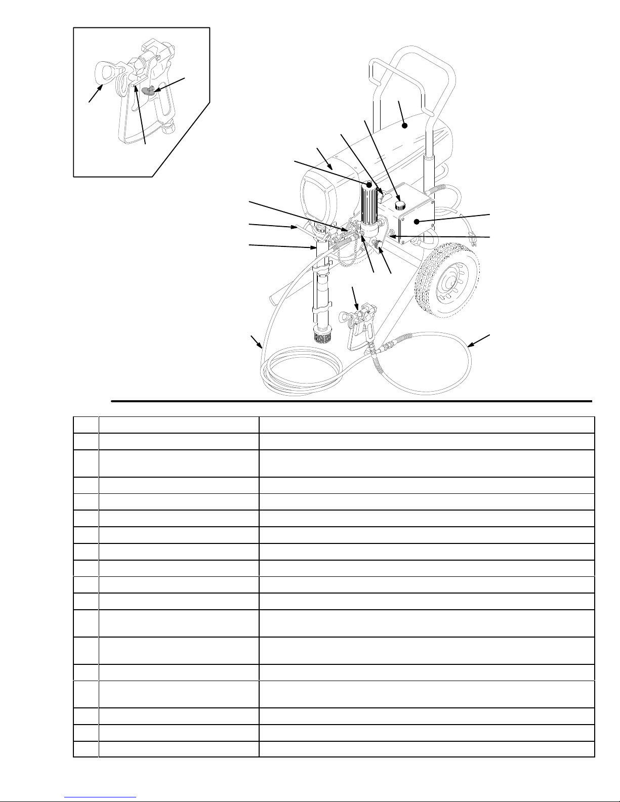
Major Components
S
A
K
Fig. 1
M
B
C
D
E
F
R
G
H
U
LTP
J
N
01888
A Motor
B
C
(Under shield shown) DC motor
Pressure Adjusting Knob
ON/OFF Switch, Circuit Breaker
, 120 V
ac, 18A, 1 phase
Controls fluid outlet pressure
Power switch that controls 120 V
breaker
D
Drive Assembly
E
Fluid Filter
F
Secondary Fluid Outlet
G
Pail Hanger
H
Displacement Pump
J
50 ft (15 m) Main Hose
K
RAC IV T
L
Contractor Gun
M
RAC IV Switch T
ip Guard
ip
T
ransfers power from DC motor to the displacement pump
Filter of fluid between source and spray gun
Second hose and spray gun is connected here
Container of fluid to be sprayed may be hung here
Pressures fluid to be sprayed through spray gun
1/4 in. ID, grounded, nylon hose with spring guards on both ends
Reverse-A-Clean (RAC) ti
High pressure spray gun with gun safety latch
RAC switch tip atomizes fluid and removes clogs from spray tip without
removing tip from spray gun
N
3 ft (0.9 m) Hose
3/16 in. ID, grounded, nylon hose used between 50 ft hose and spray
gun to allow more flexibility when spraying
P
Pressure Drain V
R
Pressure Control
alve
Relieves fluid pressure when open
Controls motor speed to maintain fluid pressure. W
adjusting knob.
S
Spray Gun Safety Latch
T
Primary Fluid Outlet Hose and spray gun is connected here
U
15/20 Amp Switch
Inhibits accidental triggering of spray gun
Allows sprayer to operate on 15A service with reduced performance
p g
uard reduce
ac power to sprayer; with circuit
s t
he ris
k o
f f
lui
d i
njectio
orks with pressure
n i
njury
Page 6

Setup
WARNING
If you supply your own hoses and spray gun, be
sure the hoses are electrically conductive, that the
gun has a tip guard, and that each part is rated for
at least
Pressure
ry caused by static sparking, fluid injection or overpressurization and rupture of the hose or gun.
3000 psi (21.0 MPa, 210 bar) Working
. This is to reduce the risk of serious inju
4.
Check the electrical service.
cal service is 120 V
grounded outlet. Do not remove the grounding
prong of the power supply cord. Do not use an
adapter
minimum 12 gauge size. Long extension cords
-
reduce sprayer performance. If 20A service is not
available, flip the 15/20 Amp switch (U) to 15 set
ting to avoid nuisance tripping of circuit breakers.
5. With the the ON/OFF switch OFF, plug the cord
into a grounded electrical outlet
20 ft. (6 m) away from the spray area.
. Extension cords must have 3 wires of a
AC, 60 Hz, 20A. Use a properly
Be sure the electri
located at least
-
-
CAUTION
T
o avoid damaging the pressure control, which
may result in poor equipment performance and
component damage, follow these precautions:
1.
Always use a nylon spray hose at least 50 ft.
(15 m) long.
2.
Never use a wire braid hose as it is too rigid to
act as a pulsation dampener
3.
Never install any shutof
filter and the hose. See Fig. 2.
1. Assemble the gun (L), 3 ft. whip hose (N) and
50 ft. hose (J).
guard yet.
2. Two gun hookup.
1/4 npsm(m) secondary hose outlet and attach a
minimum 50 ft. long hose. For more flexible gun
movement, install a 3/16 in. ID, 3 ft. whip hose be
tween the main hose and the gun.
3. Fill the packing nut/wet–cup (216)
Graco Throat Seal Liquid (TSL), supplied.
Don’t install the spray tip and tip
Remove the cap (12) from the
.
f device between the
1/3 full with
6. Flush the pump
which was left in to protect pump parts after fac
tory testing. See page 9.
Do
not install any
fluid shutof
46
12
216
-
to remove the lightweight oil
f device here
42
L
-
C
B
U
50
WARNING
FIRE AND EXPLOSION HAZARD
Proper electrical grounding is essential
to reduce the risk of fire or explosion
which can result in serious injury and
property damage. Also read
EXPLOSION HAZARD
6 308-551
on page 4.
FIRE OR
Fig. 2
KJ N
01888
Page 7
Operation
WARNING
INJECTION
T
o reduce the risk of serious injury
whenever you are instructed to relieve
pressure, follow the
Procedure
on page 10.
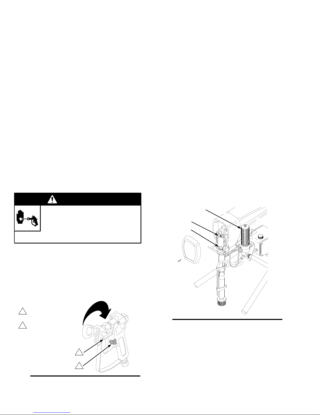
Startup (Fig. 2)
Always
is ready to operate and that you start it safely
1.
2.
3. Don’t install the spray tip and tip guard until
4. Put the suction tube (42) into the paint con-
5.
6. Disengage the gun safety latch.
use this procedure to help ensure the sprayer
For a first time startup
page 9.
Close the pressure drain valve (50).
the pump is primed!
tainer.
Lower the pressure setting
sure adjusting knob (B) fully counterclockwise.
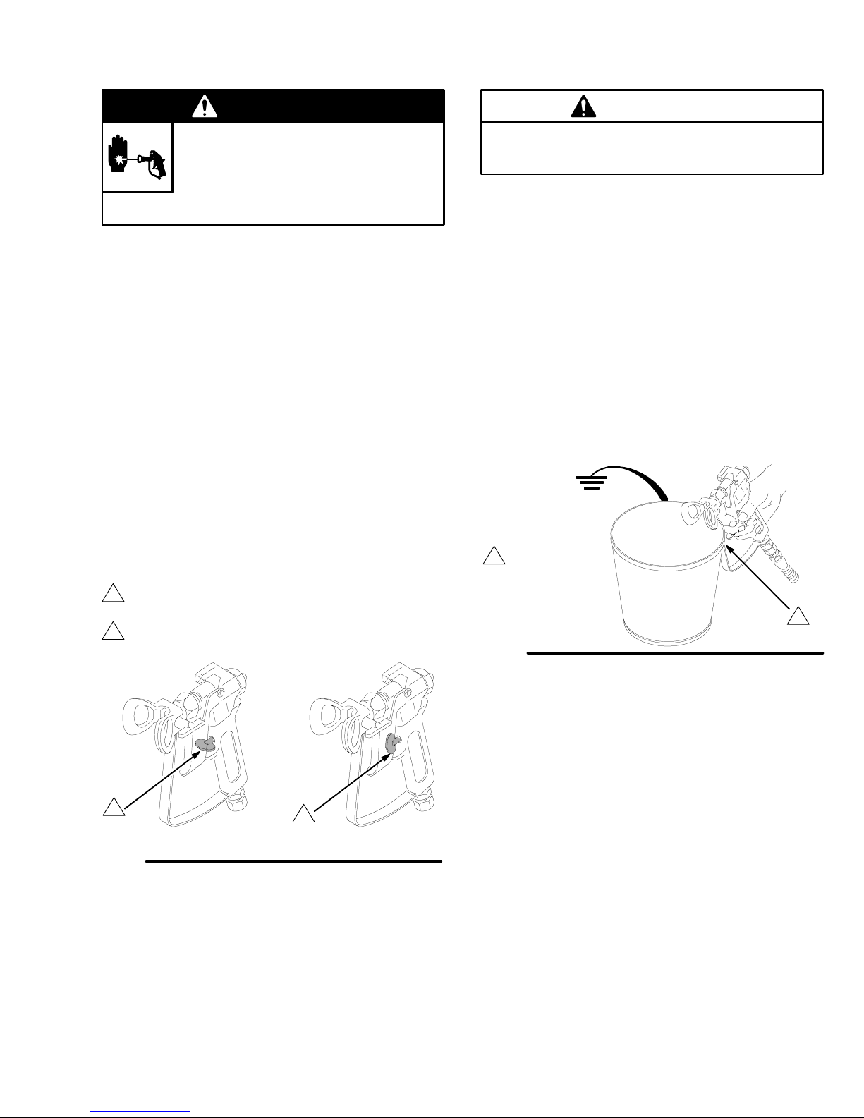
Gun
1
2
safety latch
shown engaged
Gun safety latch
shown disengaged
HAZARD
Pressure Relief
, flush the sprayer
by turning the pres
,
.
. See
See Fig 3.
CAUTION
Do
not run the sprayer dry for more than 30 sec
onds to avoid damaging the pump packings.
7. T
o prime the pump
a.
Open the drain valve.
b. T
urn the ON/OFF (C) switch to ON.
c.
Slowly increase the pressure setting until the
:
sprayer starts.
d.
When fluid is flowing from the valve, turn down
the pressure and close the valve.
e.
Hold a metal part of the gun firmly against a
grounded metal waste container
. See Fig. 4.
-
Maintain
metal to metal
1
contact when
flushing
firm
Fig. 4
-
1
0143
1
Fig. 3
f. Trigger
the gun and slowly increase the pres
sure setting until the sprayer starts. Keep the
gun triggered until all air is forced out of the
system and the paint flows freely from the gun.
g.
Release the trigger and engage the gun safety
latch. See Fig 3.
2
0137
8. Check all fluid connections for leaks
. If any
leaks are found, relieve pressure before tightening
the connections.
308-551 7
Page 8
Operation
9. Install the spray tip and tip guard.
gun safety latch. Install the spray tip. If you are
using the RAC IV tip guard, refer to manual
307–848 for installation instructions.
10.
Adjust the pressure.
a. T
urn the pressure adjusting knob clockwise
just until spray from the gun is completely at
omized. T
ging, and to decrease tip wear and extend the
life of the sprayer
sible pressure needed to get the desired re
sults.
b.
If more coverage is needed, use a larger tip
rather than increasing the pressure.
c. T
est the spray pattern. T
of the spray pattern: engage the gun safety
latch, loosen the retaining nut, position the tip
guard horizontally for a horizontal pattern or
vertically for a vertical pattern and tighten the
retaining nut.
o avoid excessive overspray and fog
, always use the lowest pos
o adjust the direction
Engage the
Cleaning a Clogged Tip
WARNING
INJECTION HAZARD
To
reduce the risk of serious injury
whenever you are instructed to relieve
Procedure
pressure, follow the
on page 10.
Pressure Relief
3. Return
gage the gun safety latch, and resume spraying.
4.
If the tip is still clogged, engage the gun safety
latch, shut of
the pressure drain valve to relieve pressure. Clean
the spray tip as shown in manual 307–848, sup
-
-
plied with the RAC IV
the switch tip to the original position, disen
f and unplug the sprayer
.
, and open
-
-
Shutdown and Care
-
-
,
1. Check the packing nut/wet-cup (216) daily.
lieve the pressure. Keep the packing nut/wet-cup
1/3 full with TSL at all times to help prevent fluid
buildup on the piston rod and premature wear of
packings. Tighten the packing nut just enough to
stop leakage. Overtightening may cause binding
and excessive packing wear
and light hammer to adjust the nut. See Fig. 6.
2. Clean the fluid filter (48) often
sprayer is stored. First relieve pressure. See man
ual 307–273 for the cleaning procedure.
3. Fill the connecting rod cavity (A)
every 100 hours of operation. Relieve pressure
first. See Fig. 6.
48
A
216
. Use a screwdriver
and whenever the
with motor oil
Re
-
-
1.
If the spray tip clogs, release the gun trigger, en
gage the gun safety latch, relieve pressure, and
rotate the RAC IV switch tip 180. See Fig. 5.
2.
Disengage the gun safety latch and trigger the gun
into a waste container
latch again.
Switch tip
1
in spraying position
Gun safety latch
2
shown engaged
Fig. 5
shown
. Engage the gun safety
1
2
-
0137
Fig. 6
4. For very short shutoff periods,
tube in the paint, relieve pressure, and clean the
spray tip.
5. Coil the hose and hang it on the hose rack
when storing it, even for overnight, to help protect
the hose from kinking, abrasion, coupling damage,
etc.
leave the suction
01892
Page 9
When to Flush
1. New
Sprayer. The sprayer was factory tested in
lightweight oil which was left in to protect pump
parts.
Before using water–base paint
spirits, then warm, soapy water
water.
, flush with mineral
, and then clean
Flushing
5.
Storage.
sprayer
pressure and leave it open.
W
ater–base paint:
spirits. Leave the system filled with mineral spirits.
Oil–base paint:
Flush as indicated below
, open the pressure drain valve to relieve
flush with water
flush with mineral spirits.
, shut of
, then mineral
f the
Before usin
2. Changing
vent.
3. Changing water–base to oil–base paint.
with warm, soapy water
4. Changing from oil–base to water–base paint.
Flush with mineral spirits, then warm, soapy water
and then clean water
g o
il–bas
e p
aint,
f
lus
h with m
Colors. Flush with a compatible sol
, then mineral spirits.
.
inera
l s
Flush
pirits.
How to Flush
A
B
CAUTION
Never
allow water to freeze in the pressure control.
-
,
Doing so prevents the sprayer from being started
and causes serious damage to the pressure control.
Push the water out with mineral spirits.
6. Startup
paint, flush out the mineral spirits with soapy water
and then clean water
flush out the mineral spirits with the paint to be
sprayed.
7.
Open the drain valve. T
increase the pressure until until the sprayer starts.
When fluid comes from the valve, close it. Hold a
metal part of the gun firmly against a metal waste
container. T
of the system and the solvent flows freely from the
gun. Release the trigger and engage the gun
safety latch.
after storage.
rigger the gun until all air is forced out
Before using water–base
. When using oil–base paint,
urn on the sprayer and
C
Fig.
7
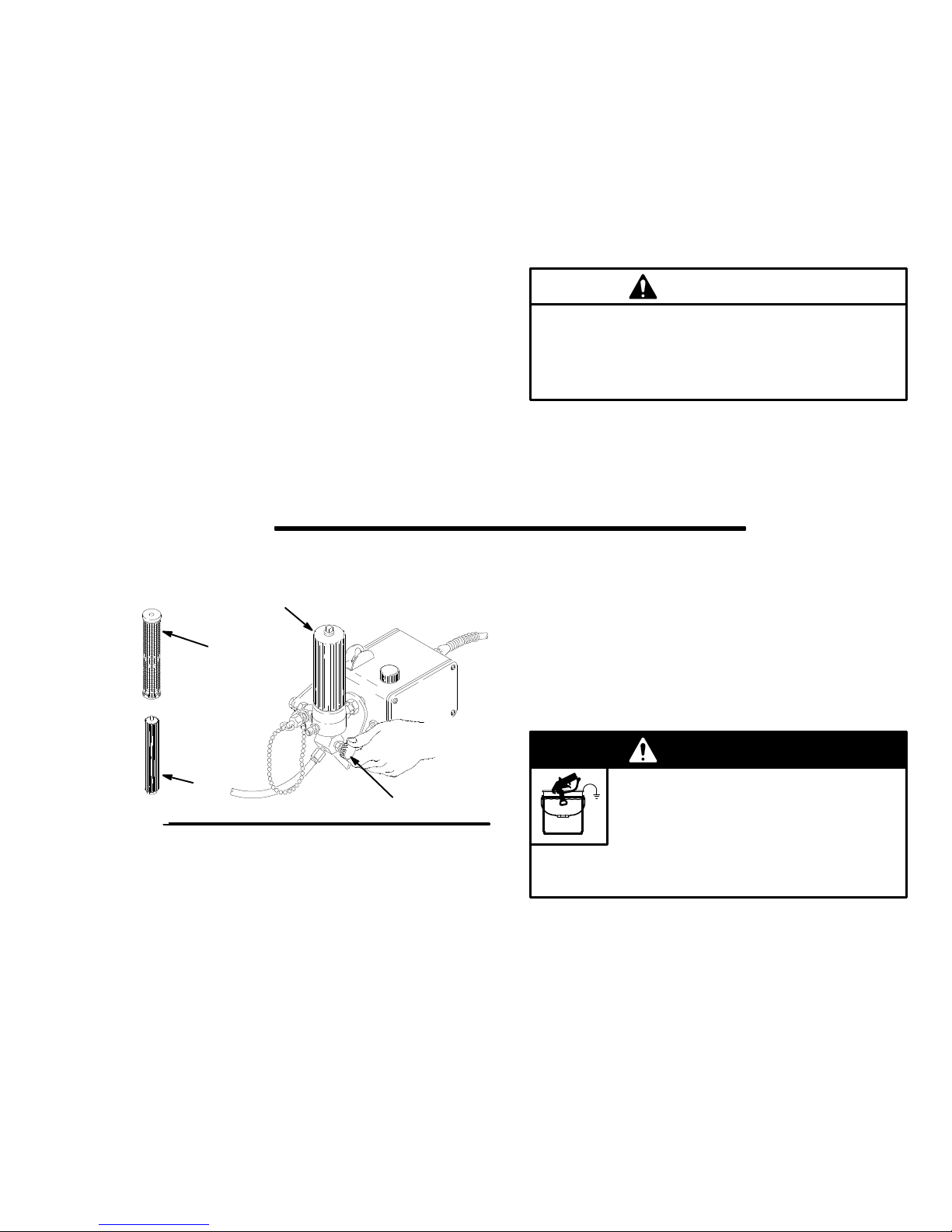
1.
Relieve pressure.
2.
Remove the filter bowl (A), support (C) and screen
(B); see manual 307–273. Install the bowl and
support. Clean the screen separately and install
after flushing.. See Fig 7.
3.
Close the pressure drain valve.
4.
Pour one–half gallon of compatible solvent into a
grounded metal pail. Put the suction tube in the
pail.
Remove the spray tip from the gun, if it is installed.
5.
6. T
urn the pressure adjusting knob all the way coun
terclockwise to lower the pressure setting.
50
WARNING
FIRE AND EXPLOSION HAZARD
T
o reduce static sparking and splashing,
always remove the spray tip from the
gun, and hold a metal part of the gun
firmly to the side of a grounded metal pail when
flushing.
8.
Remove the suction tube from the pail. Disengage
the gun safety latch and trigger the gun to force
solvent from the hose. Do not run the pump dry for
more than 30 seconds to avoid damaging the
pump packings! Relieve pressure.
9.
Leave the pressure drain valve open until you are
ready to use the sprayer again. If the screen was
removed, unscrew the filter bowl and reinstall the
clean screen. Reinstall the bowl, hand tight only
If you flushed with mineral spirits and are going to
10.
-
use a water–base paint, flush with soapy water
and then clean water. Relieve pressure.
308-551 9
.
Page 10

Troubleshooting
Pressure Relief Procedure
T
o reduce the risk of serious bodily injury
, including
fluid injection, injury from splashing fluid or solvent in
the eyes or on the skin, moving parts or electric
shock, always follow this procedure whenever you
shut of
f the sprayer
, when checking or servicing any
part of the spray system, when installing, cleaning or
changing spray tips, and whenever you stop spray
ing.
1.
Engage the gun safety latch.
2. Turn the ON/OFF switch to OFF
3.
Unplug the power supply cord.
.
Check everything in the troubleshooting table
before disassembling the sprayer
TYPE OF PROBLEM WHA
Building circuit breaker opens
.
T T
If check is OK, go to next check
Check all electrical wiring for damaged
insulation.
Check for other electrical appliances on
circuit.
O CHECK
4.
Disengage the gun safety latch. Hold a metal
part of the gun firmly to a grounded metal pail.
T
rigger the gun to relieve pressure.
5.
Engage the gun safety latch.
6. Open the pressure drain valve. Leave the pres
sure drain valve open until you are ready to
spray again.
-
If you suspect that the spray tip or hose is completely
clogged, or that pressure has not been fully relieved
after following the steps above
loosen the tip guard retaining nut or hose end cou
pling to relieve pressure gradually
pletely
. Now clear the tip or hose obstruction.
WHA
T T
When check is not OK refer to this column
Replace any damaged wiring.
Shutdown other electrical appliances on
circuit.
O DO
, VER
Y SLOWL
, then loosen com
Y
-
-
Sprayer circuit breaker opens
Sprayer will not run
Check position of 15–20 (Lo-High) amp
switch.
Check for locked motor rotor
and try to turn fan blades with a screwdriver
Check for shorted motor
check for shorts between motor leads or
between motor leads and motor frame.
Check electrical supply with voltmeter
should read 105–125 V
Check pressure control knob setting. Motor
will not run if it is at minimum setting (fully
counterclockwise).
Check for a clogged spray tip. Refer to
separate gun or tip instruction manual.
Check extension cord for visible damage.
Use a volt meter or test lamp at extension
cord outlet to check.
Check sprayer power supply cord for visible
damage such as broken insulation or wires.
Check electrical supply with volt meter
should read 105–125 V
Check for motor damage. Remove drive
housing assembly
fan by hand.
. See page 21. T
. Unplug cord
. Use ohmmeter to
. Meter
AC.
. Meter
AC.
ry to rotate
Put switch in 15 amp (LO) position.
Repair gear train or pump, if damaged.
.
the sprayer
the pressure control, if damaged.
Inspect for damage to motor brush leads.
Replace motor
Connect to outlet of correct voltage.
Slowly increase pressure setting to see if
motor starts.
Relieve pressure. Refer to separate gun or
tip instruction manual for tip cleaning.
Replace extension cord.
Replace power supply cord.
Reset building circuit breaker; replace
building fuse. T
Replace motor (1) if fan won’t turn.
, if frozen; See NOTE 1. Replace
, if necessary.
ry another outlet.
Thaw
Poor spray pattern
Check for worn spray tip.
Relieve pressure and then replace the tip.
See the separate gun or tip manual.
Page 11

Troubleshooting
TYPE OF PROBLEM WHA
If check is OK, go to next check
Motor runs and pump strokes,
but output is low or there is no
output.
Check extension cord size and length.
Check paint supply
Check for clogged intake strainer
Check for loose suction tube or loose fittings.Tighten; use thread sealant or sealing tape
Check for worn spray tip.
Check motor brushes; check for loose leads
and terminals, minimum 1/2” brush length,
broken or misaligned springs, or brushes
binding in holders. See page 12.
Check motor armature for shorts by using an
armature tester (growler).
Check to see if pump continues to stroke
when gun trigger is released. With pump on
and primed, trigger gun momentarily
release and engage safety latch. Relieve
pressure, turn of
T T
O CHECK
.
.
f and unplug sprayer
, then
.
WHA
T T
O DO
When check is not OK refer to this column
Replace cord with a larger size, grounding
type extension cord.
Refill and reprime pump.
Remove and clean strainer and reinstall.
on threads, if necessary
Follow
Pressure Relief Procedure
Warning
separate gun or tip manual.
Replace parts as needed. See page 12.
Replace motor
Service pump. See page 13.
, then replace tip. See your
. See page 19.
.
Motor runs but pump does not
stroke.
Motor is hot and runs
intermittently.
Check to see if intake valve ball and piston
ball are seating properly
Check for leaking around throat packing nut
which may indicated worn or damaged
packings.
Check displacement pump connecting rod
pin (20). See page 17.
Check for frozen or hardened paint in the
pump (39).
Be sure crank in drive housing rotates; plug
in sprayer and turn on briefly to check. T
f and unplug sprayer
of
Determine if sprayer was operated at high
pressure with small tips, which causes low
motor RPM and excessive heat build up.
Be sure ambient temperature where sprayer
is located is no more than 90F and sprayer
is not located in direct sun.
Determine in sprayer was turned on,
pressurized, but not operating for long
periods of time.
.
urn
.
Remove intake valve and clean. Check balls
and seats for nicks; replace if necessary.
See page 14. Strain paint before using to
remove particles that could clog the pump.
Replace packings. See page 13. Also check
piston valve seat for hardened paint or nicks
and replace if necessary
packing nut/wetcup.
Replace pin, if missing. Be sure retainer
spring (35) is fully in groove all around
connecting rod. See Fig. 38, page 17.
Thaw
. See NOTE 1. Plug in sprayer and turn
on. Slowly increase pressure setting to see if
motor starts.
Check drive housing assembly for damage
and replace if necessary
Decrease pressure setting or increase tip
size.
Move sprayer to shaded, cooler area, if
possible.
T
urn of
f sprayer whenever you stop spraying
for a while and relieve fluid pressure.
. T
ighten the
. See page 21.
NOTE 1:
Thaw the sprayer if water or water-based paint has frozen in it, by placing it in a warm area. Do not try to
start the sprayer until it has thawed completely
See page 15.
. If paint hardened (dried) in the sprayer
, replace the pump packings.
Page 12

Motor
Brush
NOTE: Replace
about 0.4 in (10 mm). Always check both brushes and
replace them together
220–853, and the spring clip, p/n 1
able. Order separately
NOTE:
long as the original ones. To maximize brush life, break
in new brushes by operating the sprayer for at least
one hour with no load (remove the pump connecting
rod pin).
Replacement brushes may last only half as
the brushes when they have worn to
. A Brush Repair Kit, p/n
10–816, are avail
.
-
WARNING
INJECTION HAZARD
T
o reduce the risk of serious injury
whenever you are instructed to relieve
pressure, follow the
Procedure
1.
Remove the motor cover (14) and both inspection
covers (A). See Fig 8.
2.
Push in the spring clip (D) to unhook it, and then
pull it out. See Fig 9.
on page 10.
Pressure Relief
,
9.
Reinstall the remaining parts.
14
Fig. 8
B
Part
1
No.
110–816
A
01891
C
D
1
3.
Loosen
(G) away
the brush (C) and spring (B). See Fig 10.
4.
Inspect the commutator for excessive pitting, burn
ing or gouging. A black color on the commutator is
normal. Have the commutator resurfaced by a
qualified motor repair shop if the brushes seem to
wear too fast.
5.
Install the new brush (C) so its lead is in the long
slot (K) of the holder (H). Slide the terminal (E)
under the terminal screw (F) washer
the motor lead terminal (G) is still connected at the
screw. T
Place the spring (B) on the brush (C) as shown in
6.
Fig 1
7.
Push in and hook the spring clip (D). See Fig 1
8.
Repeat for the other side.
the terminal screw (F). Pull the brush lead
, leaving the motor lead in place. Remove
. Make sure
ighten the screw
1.
. See Fig 1
1.
1.
Fig. 9
B
-
C
E
F
Fig.
10
Note:
1
2
Spring must coil
in this direction
Minimum brush length:
0.4 in. (10 mm)
G
D
H
J
K
C
B
D
CAUTION
Do not run the sprayer dry for more than 30 sec
onds while checking the brushes to avoid damag
ing the displacement pump.
2
-
-
Fig. 11
1
01227
Page 13

Displacement
Pump
Removing the Pump
WARNING
INJECTION
T
o reduce the risk of serious injury
whenever you are instructed to relieve
pressure, follow the
Procedure
1.
Flush the pump, if possible, and relieve pressure
again. Stop the pump with the piston rod in its
lowest position, if possible.
2.
Remove the hose (47), clips and drain tube (101).
Remove the suction tube (42); hold the wrench
on the pump intake valve (223) to keep the pump
from loosening. See Fig. 12.
3.
Push the retaining spring (35) up. See Fig. 13.
4.
Push out the pin (20). See Fig. 14.
on page 10.
HAZARD
Pressure Relief
WARNING
INJECTION HAZARD
Always use the special sleeve removal
tool to remove the sleeve. Other removal
,
ture, resulting in serious bodily injury
cannot be removed easily using the tool, return the
sleeve and cylinder to your Graco distributor for
removal.
Fig. 12
methods could cause the pump to rup
. If the sleeve
101
47
42
-
02553
5.
Loosen the locknut (38) and unscrew the pump
from the bearing housing (27). See Fig. 15.
Tools Needed for Pump Repair
Repair
Kit, P/N 220–877
Sleeve Removal T
Heavy duty vise
1-1/16’
’ open end wrench for Pump 220–872
2-1/4’
’ adjustable, open-end wrench
Plastic mallet
Small screwdriver
Throat Seal Liquid
Thread Sealant
NOTE:
Soak leather packings in oil before installing.
ool, P/N 220–991
Cleaning and Inspecting Parts
Clean
and inspect the parts. Pay particular attention to
the ball seat in the intake valve, which should have no
nicks or wear
outside of the piston rod, which should not be worn or
scratched. Replace worn or damaged parts.
, and to the inside of the sleeve and the
Fig. 13
Fig. 14
02554
02555
Remove and clean the sleeve when you are repacking
the pump. A special sleeve removal tool is available.
See the chart, above, for the tool number for your
pump.
Fig. 15
02556
Page 14

Displacement
Disassembly
NOTE:
220–877, are marked with an asterisk (*) in the text
and drawings. Use all the new parts in the kit.
1.
2.
3.
4. T
5.
6.
Parts included in the Packing Repair Kit, P/N
Loosen the packing nut (216) and remove the plug
(205). Unscrew the cylinder from the intake valve.
See Fig. 16.
Disassemble the intake valve. Use a pick to
remove the old gasket (202). Clean and inspect
the parts. See Fig. 17.
Reassemble the intake valve using a new gasket
(202*), ball (204*) and pin (221*). See Fig. 17.
ap the piston rod (224) out of the cylinder
Fig. 18.
Screw the sleeve removal tool’
the top of the cylinder
the sleeve out. See Fig. 19. Remove the tool.
Clean and inspect the parts.
Clamp the piston rod (224) in a vise. Loosen the
retaining nut (21
(222). See Fig. 20.
. Screw down the rod to push
1). Unscrew the piston valve
s large nut (A) into
. See
Pump
Fig. 18
Fig. 19
224
02561
A
02562
222
211
7.
Disassemble the piston and discard the packings
and glands. See Fig. 21.
8.
Remove and discard the throat packings and
glands from pump cylinder
Fig. 16
*204
*202
. See Fig. 22.
205
216
221*
02558
Fig. 20
Fig. 21
224
02563
02564
Fig. 17
14 308-551
02559
Fig. 22
02565
Page 15

Pump Reassembly
Displacement
Pump
1. Clean
the piston valve threads. One at a time,
stack the backup washer (203*), seal (215*) (with
lips facing down), and female gland (214*) on the
piston. Alternately stack the polyethylene (212*)
and leather (206*) packings (lips facing up) on the
piston. Then install the male gland (210*). See Fig.
23.
2.
Place the flats of the piston valve in a vise. T
the packing retaining nut against the piston valve
to 4 in-lb (0.35 N.m). See Fig. 24.
Note th
nut
3.
e a
. Maintai
lignment o
n this a
f the p
lignmen
isto
t t
hroug
n to the p
h S
tep
acking retainer
s 4 and 5.
Apply one drop of Locktite to the threads. Place
the ball (225*) on the piston valve. See Fig. 25.
4.
While maintaining the alignment, thread the piston
valve assembly into the piston rod just until the
piston valve nut contacts the rod. See Fig. 26.
5.
Place the flats of the rod in a vise. Carefully tighten
the piston valve nut (21
1) against the piston rod to
19 ft-lb (27 N.m). Use two wrenches to maintain
the alignment. See Fig. 27.
ighten
Fig.
25
Fig. 26
*225
02568
02569
6.
Place the male gland (208*) in the cylinder
nately stack the polyethylene (213*) and leather
packings (207*) (lips facing down). Then place the
female gland (209*) in the top of the cylinder
the packings. See Fig. 28.
*210
*212
206*
*214
Fig. 23
Torque
to 4 in-lb
(0.35 N.m)
Fig. 24
. Alter
. Seat
215*
203*
02566
02567
Torque
-
Fig. 27
to 19 ft-lb
(27 N.m)
02570
209*
*207
213*
208*
Fig.
28
02571
Page 16

Displacement
Pump
7. Loosely
install the packing nut (216) and plug
(205). See Fig. 29.
8.
Place a o-ring (217*) in the cylinder
. Slide the
sleeve in to the cylinder to seat the o-ring. See Fig.
30. Remove the sleeve.
9.
Grease the piston packings and the top edge of
the sleeve. See Fig. 31.
10.
Carefully slide the piston assembly into the top of
the sleeve. See Fig. 32.
11.
Slide the sleeve/piston rod assembly into the
bottom of the cylinder
12.
Grease the intake valve o-ring with non-silicon
. See Fig. 33.
grease. Screw the pump cylinder into the intake
valve. T
13. T
orque to 70 ft-lb (95 N.m). See Fig. 34.
ighten the packing nut (216) hand tight. Screw
the cylinder locknut (A) down to the bottom of the
external cylinder threads. See Fig. 35.
02575
Fig. 32
Fig. 29
Fig. 30
217*
205
216
02576
Fig. 33
02572
02577
Fig. 34
02573
216
A
Fig. 31
16 308-551
02574
Fig. 35
02578
Page 17

Installing the Pump
Displacement
Pump
1. Screw
2.
3.
the displacement pump into the bearing
housing (27) until the pin holes align. See Fig. 36.
Install the pin (221*). See Fig. 37.
Continue to screw the pump into the bearing hous
ing until the top threads of the pump cylinder are
flush with the face of the bearing housing and the
outlet nipple is straight back. Push the retaining
spring (35) into the groove all the way around the
connecting rod to prevent it from working loose
due to vibration. See Fig. 38.
WARNING
MOVING P
If the pin works loose, it or other parts
could break of
pumping action. These parts could be
projected through the air and result in serious bodi
ly injury or property damage, including damage to
the pump, connecting rod or bearing housing.
ARTS HAZARD
f due to the force of the
-
Fig. 37
35
-
Fig. 38
221*
02580
02581
4. T
ighten the locknut (38) to 70 ft-lb (97 N.m). See
Fig. 39.
CAUTION
If the locknut (38) loosens during operation, the
threads of the bearing housing (29) will be dam
aged. Be sure to tighten the locknut firmly
ighten the packing nut/ wet-cup just enough to
5. T
stop leakage, but no tighter
ing nut 1/3 full with Graco TSL. See Fig. 40.
. Fill the wet-cup/pack
.
-
Torque
to
70 ft-lb
(97 N.m)
-
Fig. 39
02582
Fig. 36
02579
Fig.
40
02583
308-551 17
Page 18

Pressure
4
6
Control
WARNING
INJECTION
T
o reduce the risk of serious injury
whenever you are instructed to relieve
pressure, follow the
Procedure
NOTE:
1.
Disconnect the hose (47).
2.
Disconnect the drain tube (101) from the drain
valve.
3.
Loosen the outside filter bracket nut (28).
Unscrew the swivel fitting (8) and remove the filter
4.
Remove the pressure control cover (36). Discon
nect the four motor leads. See Fig. 42.
5.
Unscrew the connector (54). Pull the wires out of
the pressure control.
6.
Remove the pressure control mounting screws
(37). Remove the pressure control. Install the con
nector (54) on the new pressure control.
7.
Install the new pressure control. Place the seal
(103) around the motor leads and push the seal
into the connector (54). See Fig. 42.
on page 10.
Refer to Fig. 41 except where noted.
HAZARD
Pressure Relief
41
40
84
,
28
13
28
8
.
-
-
Fig. 41
101
16
47
3
5
22
37
01894
Power
WARNING
INJECTION
T
o reduce the risk of serious injury
whenever you are instructed to relieve
pressure, follow the
Procedure
NOTE:
1.
Relieve pressure.
2.
Remove the back pressure control plate (16).
3.
Remove the pressure control cover
the power supply cord leads. See Fig. 42.
4.
Loosen the strain relief bushing (B). Remove the
power supply cord (23).
5.
Install the new cord.
on page 10.
Refer to Fig. 41 except where noted.
HAZARD
Pressure Relief
. Disconnect
Supply Cord
BACK
,
White
23
Black/
white (+)
Fig. 42
Black
B
Green
Black
FRONT
(–)
103
54
VIEW OF PRESSURE CONTROL
01898
VIEW OF PRESSURE CONTROL
Red
01897
Page 19

WARNING
Procedure
INJECTION
T
o reduce the risk of serious injury
whenever you are instructed to relieve
pressure, follow the
on page 10.
HAZARD
Pressure Relief
CAUTION
T
o avoid damage to the drive housing:
Do not drop the gear cluster (9), which may
stay engaged in the motor bell or in the drive
housing.
Do not lose the thrust balls (10) or drop them
between gears. The balls usually stay in the
shaft recesses, but could be dislodged. If the
balls are not in place, the bearings will wear
prematurely.
1.
Remove the motor shield (14). Remove the front
cover (31). Disconnect the hose (47).
2.
Remove the pressure control cover (36). Discon
nect the four motor leads.
3.
Unscrew the connector (54) from the pressure
control. Pull the wires through the connector
4.
Unscrew the connector (54) from the motor and
remove the conduit (22).
5.
Remove the screws (51) from the recess of the
drive housing.
6.
Remove the screws (21 and 30) from the the mo
tor end bell (F).
18
T
orque to
1
175 in-lb (19 N.m)
Bronze
2
6 oz.
Apply
3
bearing grease
4
Silver
31
32
33
1
27
49
39
Motor
,
-
.
-
18a
4
3
9
2
18b
10
7.
Use a plastic mallet to tap the displacement pump
(39) from the rear to loosen the drive housing (18)
from the motor end bell (F). Pull of
f the drive hous
ing.
8.
Remove the screws (37) holding the motor to the
frame. Lift of
9.
Mount the new motor on the frame.
10.
Slide a connector (54) over the conduit (22) of the
f the motor
.
new motor and screw two or three threads of it into
the motor
11.
Liberally grease the gear cluster (9) and pinion
. T
ighten the locknut (44) up to the motor
gear (G) and pack all bearings in the motor end
bell. Be sure the thrust balls (10) are in place.
(One ball is included with a replacement drive
housing.)
12.
Place the bronze-colored washer (18b) and THEN
the silver-colored washer (18a) on the shaft pro
truding from the big gear in the drive housing (18).
13.
Align the gears and push the drive housing (18)
straight onto the motor bell (F) and locating pins.
14.
Continue to reassemble the sprayer
.
14
64
37
21
63
F
G
10
40
41
-
.
-
54
36,15
30
63
Fig. 43
51
47
63
54
22
308-551 19
Page 20

Bearing
Housing & Connecting Rod
WARNING
INJECTION
T
o reduce the risk of serious injury
whenever you are instructed to relieve
pressure, follow the
Procedure
1
Torque
Lubricate with motor oil
2
Liberally pack roller bearing with bearing grease
3
1
on page 10.
to 175 in-lb (19 N.m)
2
K
27
49
33
3
29
HAZARD
Pressure Relief
18
H
J
NOTE: Stop
get the crank (H) in its lowest position.T
crank manually
a screwdriver
,
1.
Remove the pump. See page 13.
2.
Remove the front cover (31). Remove the bearing
housing screws (33).
3. T
ap the lower rear of the bearing housing (27) with
a plastic mallet to loosen it from the drive housing
(18). Pull the bearing housing and the connecting
rod (29) straight of
4.
Remove the pail bracket assembly (L) and reinstall
it on the new bearing housing.
5.
Inspect the crank (H) for excessive wear and re
place parts as needed.
6.
Evenly lubricate the inside of the bronze bearing
(K) with motor oil. Liberally pack the roller bearing
(J) with bearing grease.
7.
Slide the connecting rod (29) into the bearing
housing (27).
the sprayer at the bottom of its stroke to
o lower the
, rotate the blades of the motor fan with
.
f the drive housing.
-
Fig. 44
32
31
8.
Clean the mating surfaces of the bearing and drive
housings.
L
02654
9.
Align the connecting rod with the crank (H) and
align the locating pins in the drive housing with the
holes in the bearing housing (27). Push the bear
ing housing onto the drive housing or tap it into
place with a plastic mallet.
10.
Install the bearing housing screws (33). T
evenly to 175 in-lb (19 N.m).
11.
Reinstall all parts. See page 17 to install the pump.
-
orque
Page 21

Drive
WARNING
INJECTION
T
o reduce the risk of serious injury
whenever you are instructed to relieve
pressure, follow the
Procedure
NOTE:
get the crank (H) in its lowest position. T
manually
screwdriver.
1.
Remove the front cover (31). Remove the motor
shield (14).
2.
Disconnect the pump outlet hose (47).
3.
Remove the screws (33) from the bearing housing.
4.
Lightly tap the lower rear of the bearing housing
(27) with a plastic mallet to loosen it from the drive
housing (18). Pull the bearing housing and con
necting rod assembly straight of
5.
Remove the screws (51) from the recess of the
drive housing.
on page 10.
Stop the sprayer at the bottom of its stroke to
, carefully rotate the blades of the fan with a
HAZARD
Pressure Relief
o lower it
f the drive housing.
Housing
7. T
,
8.
-
9.
10.
ap the drive housing (18) with a plastic mallet to
loosen it from the motor end bell, then pull it
straight of
f.
CAUTION
T
o avoid damage to the drive housing:
Do not drop the gear cluster (9), which may
stay engaged in the motor bell or in the drive
housing.
Do not lose the thrust balls (10) or drop them
between gears. The balls usually stay in the
shaft recesses, but could be dislodged. If the
balls are not in place, the bearings will wear
prematurely.
Use approximately 6 oz. of the bearing grease
supplied with the drive housing replacement kit to
grease the gear cluster (9). Check to be sure the
thrust balls (10) are in place.
Place the bronze-colored washer (18b) and THEN
the silver-colored washer (18a) on the shaft pro
truding from the big gear in the drive housing (18).
Align the gears and push the new drive housing
straight onto the motor bell and locating pins.
-
6.
Remove the screws (30 and 21) from the motor
end bell (F).
T
orque to
1
175 in-lb (19 N.m)
Bronze
2
Apply
3
4
31
6 oz. bearing grease
Silver
49
1
33
27
2
18b
18
H
11.
Continue to reassemble the sprayer
screws (33) to 175 in-lb (19 N.m).
64
21
63
F
4
3
10
18a
9
10
63
51
. T
orque the
14
64
30
63
32
Fig. 45
47
01896
Page 22

46
28
13
28
85
34
71,
77
107
Sprayer
84
16
95
88
Parts Drawing
92
43
23
87
15
37
98
3
6
14
32
4
12
31
33
49
27
Ref 101
29
18
46
10
50
18b
48
9
69
8
18a
57
10
51
37
1
99
41
40
63
63
21
97
37
64
109
54
22
30
63
40
41
2
82
64
91
81
64
35
100
101
102
20
75
38
39
42
7
19
47
108
53
Ref
37
60
26
58
11
Page 23

Sprayer Parts List
Model
223–773, Series A
Basic Sprayer
Ref.
No. Part No. Description Qty.
1 220–854 MOTOR KIT
, CSA certified, Includes items 1–109
Includes 1 of item 92
2 290–058
3 290–059
4 290–057
6 220–636 CART 1
7 187–147 STRAINER 1
8 155–665
9 220–637 GEAR REDUCER 1
10 100–069
11 104–811 HUBCAP 2
12 220–285 CAP 1
13 100–322 LOCKW
14
15
16 185–539 BRACKET
18 220–879 DRIVE HOUSING KIT
223–153 MOTOR SHIELD KIT 1
110–037 SCREW
LABEL, identification, motor cover
LABEL, identification, motor cover
LABEL, identification, front cover
UNION, adapter; 3/8” npsm swivel
x 3/8 npt(m)
BALL, steel; 1/4” dia.
ASHER, ext., 7/16”
, pnh; 10–24 type C x 1/2”
, mounting
Includes items 18 a and 18b,
and one of item 10
18a 183–209 BEARING, thrust 1
18b 106–227 SPACER 1
19 186–227 HANGER, pail 1
20 183–210
21 100–644 SCREW
22
23 POWER SUPPLY CORD
24 107–264
26 154–636 WASHER 2
27 220–639 BEARING HOUSING KIT 1
28 150–513 NUT
29 220–640 CONNECTING ROD KIT 1
30 100–643 SCREW
31 183–168
32 108–850
33
34
35 183–169
36 185–000 COVER, pressure control 1
37 110–963 CAPSCREW
38 183–170 NUT
39 220–872 DISPLACEMENT PUMP
40 100–214 LOCKW
41 100–188 NUT
42 183–423 TUBE, INTAKE 1
065–312 CONDUIT, electrical, 13 in.
238–342
238–167
110–141 CAPSCREW
186–374 ADAPTER, elbow
PIN, straight, 3/8 x 1–1/8”
, soc head, no. 1/4–20 x 3/4”
For Models 231–351, 231–352
For Model 223–773
TERMINAL, female
, jam; 7/16”
, socket head, no. 1/4–20 x 1”
COVER, housing 1
SCREW
1/4–18 npt(m x f)
SPRING, retaining
5/16–18 x 3/4”
, filh; no. 8–32 x 1–1/4”
, sch; 3/8–16 x 1–1/5”
, special;
, flange head,
, hex, 1 13/16 unc–2b
see page 24
ASHER, spring; 5/16”
, heavy hex; 5/16–18 unc–2a
Ref.
No. Part No. Description Qty.
43 PRESSURE CONTROL KIT 1
includes
items 13, 16, 23, 2 of 28, 34,4 of 84
223–803 NEW
223–804 REBUILT
224–018 NEW
46
1
47 220–849
1
48 214–570
1
1
49 106–115 LOCKWASHER,
50 221–077 PRESSURE DRAIN VALVE 1
51 108–849 CAPSCREW
1
53 108–691
54 108–460 CONNECTOR 2
1
56 102–556 RIVET
57 178–034 TAG, WARNING 1
58 101–242
1
59 206–994 THROA
60 179–81
4
63
1
64 108–865 SCREW
69 110–814 NUT
71 177–762
1
75 183–461
77 290–060 LABEL, IDENTIFICATION 1
81 185–384 BRACKET 2
82 110–240 NUT 2
1
84 106–078 SCREW
2
85 100–040 PLUG 1
1
87 106–170 BUSHING, strain relief 1
88 185–565
1
89 100–035 SCREW
1
2
90 157–021 LOCKWASHER,
162–453
1
105–510
KIT
,
for
Models 231–351 & 231–352
KIT
,
for Models 231–351
& 231–352
KIT
,
for
Sprayer 223–773
NIPPLE, hex; 1/4 npsm x 1/4 npt,
1–3/16” long
HOSE, 3/8 npsm(f) x 14–1/2”
FLUID FIL
see
includes one of items 46 and 85
PLUG, tubing
RING, retaining
WHEEL 2
LOCKW
LABEL, W
ADAPTER; 3/8 npsm x 1/4 npt
LABEL, control
inside
TER
manual 307–273 for parts
spring; 3/8”
, sch; 1/4–20 x 3”
, blind; 1/8” dia.
T SEAL L
ASHER, spring, 1/4”
, pnh; 8–32 x 3/8”
, retainer
, flat hd; 10–24 x 3/8”
, pnh; 8–32 x 5/16”
pressure control
IQUI
D 8 oz. (
ARNING 1
internal, No. 8
inside pressure control
91 100–020 LOCKWASHER, .194” ID 2
2
92
93 110–619
2
95 178–035
97 185–951 LABEL, DANGER 1
4
98 185–952 LABEL, DANGER 2
4
99 185–955 LABEL, DANGER 1
100 186–490 CLIP
1
101 186–495
1
102 181–102 CLIP
103 107–447 SEAL 2
107 112–152 SWITCH, circuit breaker
7
108 105–659 BOOT
1
1
109 113–605 BOOT
7
7
187–656
105–679
GASKET 2
LABEL, Caution
LABEL, Caution
, spring
TUBE, drain
, spring
, toggle
SWITCH, toggle
, circuit breaker 1
Replacement Danger and W
arning labels, tags and cards
are available at no cost.
0.2
7 l
, 1
10V 1
1
1
1
2
1
1
4
2
2
2
2
iter) 1
6
10
2
1
4
1
1
1
1
1
1
1
1
1
1
Page 24

Displacement
Model
220–872, Series A
Displacement Pump
Includes items 202 to 225
Pump Parts Drawing and List
205
Ref.
No. Part No. Description Qty.
202* 107–098 PACKING, o-ring, PTFE 1
203* 108–690
204* 108–775 BALL; sst 1
205 183–171 PLUG 1
206* 183–174 V-P
207* 183–175 V-P
208* 183–176
209* 183–177
210* 183–178
211
212* 183–182 V-PACKING, plastic 3
213* 183–183 V-PACKING, plastic 3
214* 183–653 WASHER, backup 1
215* 183–185
216
217* 183–172 O-RING, PTFE 1
218
219
220
221* 183–173
222
223
224
225* 101–947
*
183–179
183–186
183–361
183–181
183–180
220–631
220–629
220–630
These parts are also included in Repair Kit 220–877,
which may be purchased separately
SEAL, u–cup, polyurethane
ACKING, leather
ACKING, leather
GLAND, male
GLAND, female
GLAND, male
NUT
, hex, retaining
GLAND, female
NUT
, packing
SLEEVE, cylinder 1
CYLINDER 1
GUIDE, ball 1
PIN, ball stop
VAL
VE, piston
VAL
VE, intake
ROD, piston 1
BALL
.
216
224
209*
1
225*
2
2
1
1
1
*207
1
1
1
213*
208*
*212
211
210*
206*
219
1
1
1
1
215*
203*
214*
222
SLEEVE
REMOV
AL T
OOL 220–991
Use to remove a sleeve that is stuck.
Purchase separately
.
217*
218
220
*204
*202
221*
223
Page 25

Accessories
DANGER
LABELS
The English language DANGER label shown on
page 1 is also on your sprayer
. If you have paint
ers who do not read English, order one of the fol
lowing labels to apply to your sprayer
. The draw
ing below shows the best placement of these la
bels for good visibility
.
Order the labels directly from Graco, free of
charge. T
oll Free:
1–800–367–4023
French 185–956
Spanish 185–961
German 186–041
Greek 186–045
Korean 186–049
English 185–953
Apply
language here
MOT
OR BRUSH KIT
DISPLACEMENT PUMP P
other
220–853
ACKING KIT
220–877
See contents on page 24.
SUCTION
TUBE KIT
208–259
55 gallon (200 liter) size
-
-
-
-
Includes:
Ref
No. Part No. Description Qty
1 156–589 UNION, 90
2 214–961
3 156–591 ELBOW
4 156–593 P
5 100–220 THUMBSCREW
6 176–684
7 156–592 TUBE, riser 1
8 159–100 RETAINER, screen 1
9 161–377 SCREEN, filter 1
10 159–101 NUT
HOSE, cpld 3/4 npt(mbe); 3/4” ID; nylon;
6 ft (1.8 m); spring guard one end
ACKING, o-ring, nitrile
ADAPTER, bung
, screen retainer
;3/4 npt(f) x 3/4 npt(f) sw
, 90; 3/4 npt x 1–1/2 – 24 ns
, 5/16–18 X 1”
1
1
1
1
1
1
2
3
4
6
5
7
SUCTION TUBE KIT
208–920
5 gallon (19 liter) size
Includes:
Ref
No. Part No. Description Qty
1 101–818 CLAMP
2 160–327 UNION, 90
3 170–705 ADAPTER, intake 1
4 170–706 HOSE, 1” ID x 48”; nylon 1
5 170–957 TUBE, suction 1
6 181–072 STRAINER 1
, hose
swIvel; 3/4 npt(m x f)
5
4
6
1
2
3
8
9
10
2
1
1
Page 26

Notes
Page 27

Technical
Power
Requirements (full output)
W
orking Pressure Range
Cycles/Gallon (liter)
Power
Cord
.
. . . . . . . . . . . . . . .
Inlet
Paint Strainer
Outlet Paint Filter
Pump Inlet Size
Fluid
Outlet Size
Wetted Parts:
Displacement Pump
Filter
.
. . . . . . . . . .
.
. . . . . . . . . . . . . . . . .
.
. . . . . . . . . . . . . . . . . . . . . . . . . . . .
.
. . . . . . . . . . . . . . .
Data
120 V
. . . . . . . .
1
phase, 18 amp minimum
.
. . . . . . . . . . . . . . . . . . .
(0–21.0
.
. . . . . . . . . . . . . . . . . . . . . . . . .
No. 12 A
.
. . . . . . . . . . . . . . .
Stainless
Stainless
.
. . . . . . .
Polyethylene,
Aluminum, Carbon steel, Stainless steel,
Carbon steel, Polyurethane,
MPa, 0 – 210 bar)
WG, 3 wire, 10’ (3 m)
16 mesh (1
steel screen, reusable
60 mesh (250 micron)
steel screen, reusable
1/4 npsm from fluid filter
PTFE,
AC, 60Hz,.
0–3000 psi
104 (27.5)
190 micron)
3/4 npt(m)
Delrin, Leather
Weight
Height
Length
Width
Dimensions
122 lb (55.5 kg)
32 in. (813 mm)
24.25 in. (616 mm)
22.5 in. (572 mm)
NOTE:
the DuPont Company
Delrin is a registered trademark of
.
Page 28

Graco
Graco
warrants all equipment manufactured by Graco and bearing its name to be free from defects in material and workmanship on the
date
of sale by an authorized Graco distributor to the original purchaser for use. With the exception of any special, extended, or limited
warranty
determined
dance
This
faulty
stitution
Graco equipment with structures, accessories, equipment or materials not supplied by Graco, or the
installation,
This
verification
equipment
in
transportation.
THIS
NOT
published
with Graco’
warranty does not cover
installation, misapplication, abrasion, corrosion, inadequate or improper maintenance, negligence, accident, tampering, or sub
of non–Graco component parts. Nor shall Graco be liable for malfunction, damage or wear caused by the incompatibility of
warranty is conditioned upon the prepaid return of the equipment claimed to be defective to an authorized Graco distributor for
of the claimed defect. If the claimed defect is verified, Graco will repair or replace free of charge any defective parts. The
material or
will be returned to the original purchaser transportation prepaid. If inspection of the equipment does not disclose any defect
W
ARRANTY IS EXCLUSIVE, AND IS IN LIEU OF ANY OTHER W
LIMITED T
by Graco, Graco will, for a period of twelve months from the date of sale, repair or replace any part of the equipment
by Graco to be defective. This warranty applies only when the equipment is installed, operated and maintained in accor
s written recommendations.
, and Graco shall not be liable
operation or maintenance of structures, accessories, equipment or materials not supplied by Graco.
workmanship, repairs will be made at a reasonable charge, which charges may include the costs of parts, labor
O WARRANTY OF MERCHANTABILITY OR WARRANTY OF FITNESS FOR A PARTICULAR PURPOSE.
Standard W
for general wear and tear
ARRANTIES, EXPRESS OR IMPLIED, INCLUDING BUT
arranty
, or any malfunction, damage or wear caused by
improper design, manufacture,
, and
-
-
Graco’s
remedy (including, but not limited to, incidental or consequential damages for lost
other incidental or consequential loss) shall be available. Any action for breach of warranty must be brought within two
date
Graco
with
by
purchaser
In
hereunder,
breach
FOR GRACO CANADA CUSTOMERS
The
entered into, given or instituted pursuant hereto or relating directly or indirectly hereto, be drawn up in English. Les parties reconnais
sent
exécutés,
sole obligation and buyer’s sole remedy for any breach of warranty shall be as set forth above.
of sale.
makes no warranty
accessories, equipment, materials or components sold but not manufactured by Graco. These items sold, but not manufactured
Graco (such as electric motors, switches, hose, etc.), are subject to the warranty
with reasonable assistance in making any claim for breach of these warranties.
no event will Graco be liable for indirect, incidental, special or consequential damages resulting from Graco supplying equipment
TO
or the furnishing, performance, or use of any products or other goods sold hereto, whether due to a breach of contract,
of warranty
parties acknowledge that they have required that the present document, as well as all documents, notices and legal proceedings
avoir convenu que la rédaction du présente document sera en Anglais, ainsi que tous documents, avis et procédures judiciaires
donnés ou intentés à la suite de ou en rapport, directement ou indirectement, avec les procedures concernées.
PLACE AN ORDER
, and disclaims all implied warranties of merchantability and fitness for a particular purpose in
, the negligence of Graco, or otherwise.
Graco
, contact your Graco distributor
Phone Number
, or call this number to identify the distributor closest to you:
1–800–367–4023 T
oll Free.
profits,
lost sales, injury to person or property
, if any
, of their manufacturer
The buyer agrees that no other
(2)
. Graco will provide
, or any
years of the
connection
-
Manual
Models
All
written and visual data contained in this document reflects the latest product information available at the time of publication.
Foreign Offices:
231–351 and 231–352 are obsolete and were removed from this manual.
Graco reserves the right to make changes at any time without notice.
Sales Offices:
Belgium, Canada, England, Korea, France, Germany
GRACO INC. P.O. BOX 1441
PRINTED
IN U.S.A. 308–551 December 1994, Revised December 1997
Change Summary
Minneapolis, Detroit, Los Angeles
MINNEAPOLIS, MN
http://www.graco.com
, Hong Kong, Japan
55440–1441
 Loading...