

Page 1
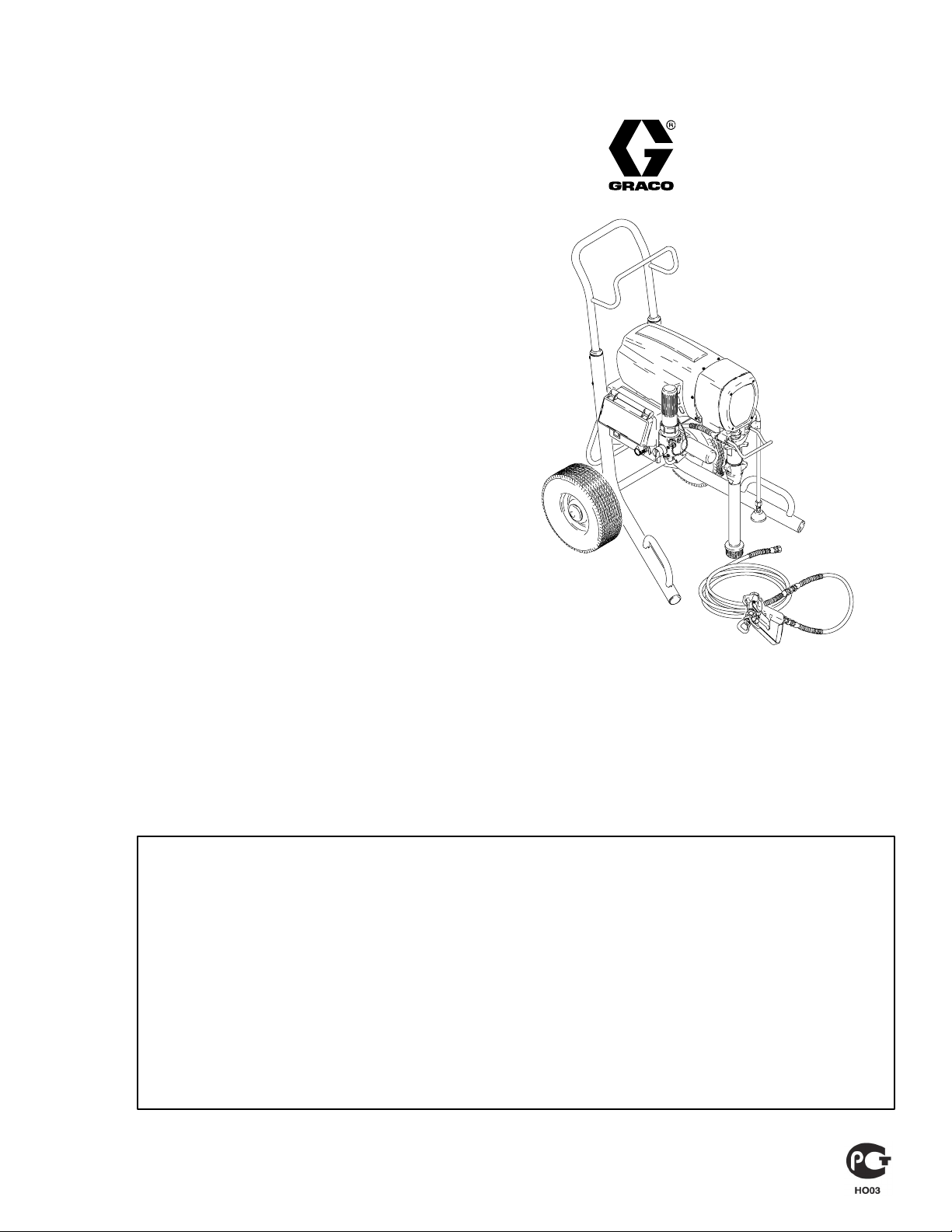
Ultra Maxt
309273
Electric Airless Sprayers
Operating Instructions
3300 psi (227 bar 22.7 MPa) Maximum Working Pressure
How To Perform:
Rev. D
S Component Identification 3. . . . . . .
S Setup 4. . . . . . . . . . . . . . . . . . . . . . . . . . .
S Startup 7. . . . . . . . . . . . . . . . . . . . . . . . . .
S SMARTCONTROLt 9. . . . . . . . . . .
S Cleanup 11. . . . . . . . . . . . . . . . . . . . . . . .
S Trouble Shooting 15. . . . . . . . . . . . . .
S Maintenance 16. . . . . . . . . . . . . . . . . . .
S Storage 16. . . . . . . . . . . . . . . . . . . . . . . .
S Tip Wear 16. . . . . . . . . . . . . . . . . . . . . . .
The intent of these instructions is to provide the new painter with a quick and easy reference to
become familiar with airless sprayers. This does not replace the Instruction Manual supplied
with this sprayer. Read and understand the instructions and warnings in that manual.
Important Note: The Graco Standard product line has a wide range of sprayer units that vary
slightly. The basic operations procedures are the same for all sprayers. Some illustrations may
not be applicable to the particular sprayer purchased.
Tools Required:
D Two adjustable wrenches
D Two 5 gallon metal pails
D Grounding wires and clamps for pails
D Pencil
Suggested proper clothing:
D Respirator
D Safety glasses
GRACO INC. P.O. BOX 1441 MINNEAPOLIS, MN 55440–1441
ECOPYRIGHT 2000, GRACO INC.
Graco Inc. is registered to I.S. EN ISO 9001
Page 2

WARNING
Fire and explosion hazard: Solvent and paint fumes can
ignite or explode.
To help prevent a fire and explosion:
DUse only in an extremely well ventilated area.
DEliminate all ignition sources; such as pilot lights, cigarettes
and static arcs from plastic drop cloths. Do not plug or
unplug power cords or turn lights on or off in spray area.
DGround Sprayer, object being sprayed, paint and solvent
pails.
DHold gun firmly to side of grounded pail when triggering into
pail.
DUse only conductive airless paint hose.
DDo not use 1,1,1-trichloroethane, methylene chloride, other
halogenated hydrocarbon solvents or fluids containing such
solvents in pressurized aluminum equipment. Such use
could result in a chemical reaction, with the possibility of
explosion.
DTo reduce risk of electric shock, use grounded outlet
only. Shut OFF and unplug when repairing.
Fluid injection and high pressure hazard: High pressure
spray or leaks can inject fluid into the body.
To help prevent injection, always:
DEngage trigger safety latch when not spraying.
DKeep clear of nozzle and leaks.
DNever spray without a tip guard.
DDo PRESSURE RELIEF if you stop spraying or begin
servicing sprayer.
DDo not use components rated less than sprayer Maximum
Working Pressure.
DNever allow children to use this unit.
If high pressure fluid pierces your skin, the injury might
look like “just a cut”. But it is a serious wound! Get immediate
medical attention.
PRESSURE RELIEF – Do this when cleaning, repairing or shuting down sprayer
1. Turn pressure to lowest setting.
Turn power OFF.
Unplug sprayer.
2. Trigger gun to relieve pressure.
3. Put drain tube in pail.
Turn prime valve down.
WASTE
RESÍDUOS
À JETER
DESECHO
2 309273
Page 3

Digital Display
(Not available on all models)
Power Switch
Component Identification
15/20A Switch
Use 15A if sprayer
causes circuit
breakers to trip
(1095/1595 only)
Pressure Control
Prime Valve
Filter
Drain Tube
Note:Unclip drain
tube for best filter
drainage
Suction Tube
Prime/drain position
Paint position
AutoClean Valve
(Not available on all models)
Spray Gun Trigger Safety
Put trigger safety ON
when not spraying.
Contractor II
safety OFF
safety ON
Contractor
Take trigger safety OFF
before triggering gun.
3309273
Page 4

Setup
1. Connect Graco airless hose to sprayer.
Tighten securely.
2. Connect other end of hose to gun.
3. Tighten securely.
4. Remove tip guard.
4 309273
Page 5

5. Check inlet strainer for clogs and debris.
Approximate Fill Level
6. Fill throat packing nut with TSL to prevent
premature packing wear.
Do this each time you spray.
5309273
Page 6

7. Turn power OFF.
8. Plug power supply cord into a properly grounded
electrical outlet.
9. Turn prime valve down.
PAINT
6 309273
10.Place suction tube and drain tube in grounded
metal pail partially filled with flushing fluid. Attach
ground wire to pail and to true earth ground. Do 1.
– 5. of Startup to flush out storage oil shipped in
sprayer. Use water to flush water base paint and
mineral spirits to flush oil base paint and storage
oil.
FLUSH
Page 7

Startup
1. Turn prime valve down.
Turn pressure control to lowest pressure.
2. Turn power ON.
3. Increase pressure enough to start motor
and allow fluid to circulate for 15 seconds; turn pressure down, turn prime
valve horizontal.
15 SEC
4. Take spray gun trigger safety OFF.
5. Hold gun against grounded metal
flushing pail. Trigger gun and increase
fluid pressure slowly until pump runs
smoothly.
safety OFF ContractorContractor II
FLUSH
Note: Inspect fittings for leaks. Do not stop leaks with your hand or a rag! If leaks
occur, do Pressure Relief. Tighten leaky fittings. Repeat Startup, 1. – 5. If no
leaks, continue to trigger gun until system is thoroughly flushed. Proceed to 6.
7309273
Page 8

PAINT
6. Place siphon tube in paint pail.
7. Trigger gun again into flushing fluid pail until
paint appears. Assemble tip and guard, page 8.
FLUSH
General Surfaces Tip Recommendations Chart
Fan Width (in.)
at 12 in.
S
S
S
S
S
S
S
S
S
S
S
S
SS
S
SS
S
S
SS
S
SS
S
S
S
S
Surfaces Materials
Wood Interior Cabinets, Paneling
Interior Walls or Ceilings
Drywall, Plaster
Over Hang
Masonry
Block, Stucco, Concrete
Wood Exterior
Shingle, Siding, Shiplap
Open Joist and Ceiling
Areas
Stain, Sanding
Sealer, Lacquer,
Varnish, Shellac
Latex, Vinyl, Acrylic
Primers, Enamels
Latex, Vinyl, Acrylic,
Oil Base Alkyds
Exterior Stains,
Latex, Vinyl, Acrylic
Mil White, Hi Builds
Filter
Mesh
100
60
60
60
60
60
6–8 8–10 10–12 12–14
S
S
S
Orifice
Size (in.)
.011
.013
.015
.017
.019
.015
.017
.019
.017
.019
.021
.017
.019
.021
.019
.021
.023
8 309273
Page 9

SwitchTip and Guard Assembly
1. Insert SwitchTip.
Insert seat and OneSeal.
2. Screw assembly onto gun. Hand tighten.
SwitchTip
seat
OneSeal
SMARTCONTROLt
(Not available on all models*)
Operation
Press SMARTCONTROL button to cycle through
PRESSURE – GAL/LTR – TIMER displays
DPRESSURE: Fluid pressure at the sprayer
DGAL/LTR: Accumulated total of gallons/liters sprayed
DTIMER: Duration of AutoClean flush cycle
NOTE: The SMARTCONTROL button is not
active if pressure is above 200 psi
Error Codes
Sprayer stops and displays error code if fault
occurs
After fault has been corrected or Timer
reaches zero, turn sprayer OFF and then
ON to reset SMARTCONTROL
* Models not equipped with digital displays:
Error codes are displayed inside SMART-
CONTROL. Refer to Manual 309255 for instructions.
High pressure limit
Pressure transducer fault
Line voltage too high
Too much current
Motor overheated
Pressure > 2000 psi while in Flush Timer Mode
Line voltage too low
Pressure is below 200 psi
Digital display switches are not set
9309273
Page 10

Spray Test Pattern
heavy
edges
1. Trigger gun and spray test pattern.
Slowly adjust pressure to eliminate
heavy edges. Use smaller tip size if
pressure adjustment can not eliminate
heavy edges.
2. Hold gun perpendicular, 10–12 in.
(25–30 cm) from surface. Spray back
and forth. Use strokes overlapped by
50%. Start gun movement before triggering gun and release trigger before
stopping gun movement.
Clearing Tip Clogs
10 309273
1. Release trigger, put trigger safety ON.
Rotate SwitchTip. Take trigger safety
OFF and trigger gun to clear the clog.
Never point gun towards your hand
or into a rag!
2. Put trigger safety ON, return SwitchTip
to original position, take trigger safety
OFF and continue spraying.
Page 11

Cleanup
Perform AutoClean procedure (Manual 309278) or follow conventional
flushing/cleaning procedure that follows:
1. Turn power OFF.
2. Turn pressure to lowest setting.
Trigger gun to relieve pressure.
3. Turn prime valve down.
4. Remove filter assembly and
assemble gun without filter.
PAINT
ti2874a
ContractorContractor II
11309273
Page 12

FLUSH
5. Remove guard and SwitchTip.
6. Clean filter, guard and SwitchTip
in flushing fluid.
7. Remove siphon tube set from paint and place
in flushing fluid. Use water for water base
paint and mineral spirits for oil base paint.
PAINT
FLUSH
8. If sprayer has a filter, unscrew bowl, remove
filter. Assemble without filter. Clean filter.
12 309273
Page 13

9. Turn power ON.
10.Turn prime valve horizontal.
11. Hold gun against paint pail.
Take trigger safety OFF.
Trigger gun until flushing
fluid appears.
12.Move gun to flushing pail, hold
gun against pail, trigger gun to
thoroughly flush system.
Release trigger and put trigger
safety ON.
13.Turn prime valve down and allow
flushing fluid to circulate for 20
seconds to clean drain tube.
PAINT
FLUSH
13309273
Page 14

PAINT
14.Raise siphon tube above flushing fluid
and run sprayer for 15 to 30 seconds to
drain fluid. Turn power OFF.
FLUSH
Note: If flushing with water, flush again with mineral spirits or Pump
Armor, but do not repeat 8. or 14. This leaves a protective
coating in the system to help prevent freezing or corrosion.
15.Make sure plastic center tube is tightened
securely. Install filter bowl and filter. Hand
tighten filter bowl. Install filter assembly
into gun. Hand tighten gun handle.
FLUSH
16.Wipe sprayer, hose and gun with a rag
soaked in water or mineral spirits.
17.Clean tip, guard and gasket with a soft
bristle brush to prevent part failure due
to dried materials. Assemble parts and
attach loosely onto gun.
14 309273
Page 15

Trouble Shooting
TYPE OF PROBLEM
D Sprayer does not
respond
D Sprayer will not prime
or takes too long to
prime
D Sprayer loses prime
while spraying
D Sprayer does not
have enough pressure at gun or pressure drops off
WHAT TO CHECK
If check is OK, go to next check
1. Check if error code is displayed, page 9. 1. Refer to your repair manual.
1. Air in paint pump 1. Open prime valve to purge air from paint
2. Inlet strainer clogged 2. Clean strainer
3. Suction tube is loose 3. Tighten fittings
4. Lower ball is stuck
NOTE: Caused by insufficient cleaning and/or
not leaving paint thinner in sprayer.
1. Suction tube is loose 1. Tighten fittings
2. Lower ball not sealing on down stroke 2. Check for:
1. Spray tip worn out 1. Replace spray tip
WHAT TO DO
When check is not OK refer to this column
pump
4. Clean lower ball
• Large debris holding ball open
• Worn or scarred lower ball
• Inlet strainer not being used
D Sprayer packings
wear out too quickly
2. Filters clogged 2. Clean filters
3. Filtration being used for wrong coatings
(i.e. block fillers, elastomerics)
4. Wrong size filter mesh 4. Select coarser filter mesh. 30 instead of 60,
5. Hose too long and/or wrong size diameter. 5. Check sprayer instruction manual for cor-
1. Operating sprayer with clogged or no inlet
strainer
2. Priming sprayer without using prime valve 2. Prime sprayer with prime valve
3. Upper packings have not been inspected/adjusted on regular basis
4. Throat seal liquid not being used 4. Keep packing nut/wet cup 1/3 full with
5. Water or paint being left in sprayer 5. Always leave paint thinner in sprayer
6. Worn pump cylinder 6. Replace pump cylinder
7. Kinked or clogged suction tube 7. Replace suction tube
8. Spraying aggressive coatings
(i.e. low and latex, zinc coatings)
9. Unrealistic expectations of packing life 9. Packing life varies with fluids sprayed and
3. Operate with no filter or change coating
60 instead of 100
rect size hose
1. Clean/install inlet strainer
3. Adjust upper packings after spraying
2 – 5 gallons of paint and then weekly
throat seal liquid
8. Use alternate packing materials. Consult
your sprayer instruction manual
pressures used
D Premature wear on
prime valve
1. Pressure being relieved at prime valve and
not at gun
2. Water or paint being left in sprayer 2. Always leave mineral spirits or Pump
1. Relieve pressure at gun
Armor in sprayer
15309273
Page 16

Maintenance
Daily:
Inspect, clean and replace as needed
D Manifold filter, gun filter and inlet stainer
D Wet cup for leakage, tighten if needed
D TSL level
D Gun trigger safety
D Tip wear, replace if necessary
D Electric cord and plug
Weekly:
D Check tightness of wet cup.
D Inspect all high pressure paint hoses.
Annually:
D Schedule maintenance check at an
authorized Graco repair center
Storage
1. Perform Cleanup, page 11
2. Wrap power cord and
spray hose around sprayer
Tip Wear
Worn Tips Waste Paint
Cost Money!
SPRAY PATTERN WIDTH
in inches (millimeters)
TIP OPENING ENLARGEMENT
FLOW RATE
in gpm (lpm)
Note: A 515 tip produces a 10 in. pattern width when measured 12 in. from tip to work
surface; spraying paint with viscosity of 20 sec #4 Zahn cup and at 1600 psi
(110 bar, 11 MPa)
NEW
12
(305)
New Tip
.015
1/4
(.87)
11
(280)
Worn to
.017
1/3
(1.14)
9
(229)
Worn to
.019
3/8
(1.4)
WORN
OUT
5.5
(140)
Worn to
.021
1/2
(1.74)
Graco Phone Number
TO PLACE AN ORDER, contact your Graco distributor, or call 1–800–690–2894 Toll Free to identify a distributor near you.
International Offices: Belgium, Korea, Hong Kong, Japan
GRACO INC. P.O. BOX 1441 MINNEAPOLIS, MN 55440–1441
16 309273
Sales Offices: Minneapolis, Detroit
www.graco.com
PRINTED IN U.S.A. 309273 12/2000 Revised 3/2003
 Loading...