

Page 1
INSTRUCTIONS-PARTS LIST
308854
KEEP FOR REFERENCE.
Read this and all related manuals for
important warnings and instructions.
INSTRUCTIONS
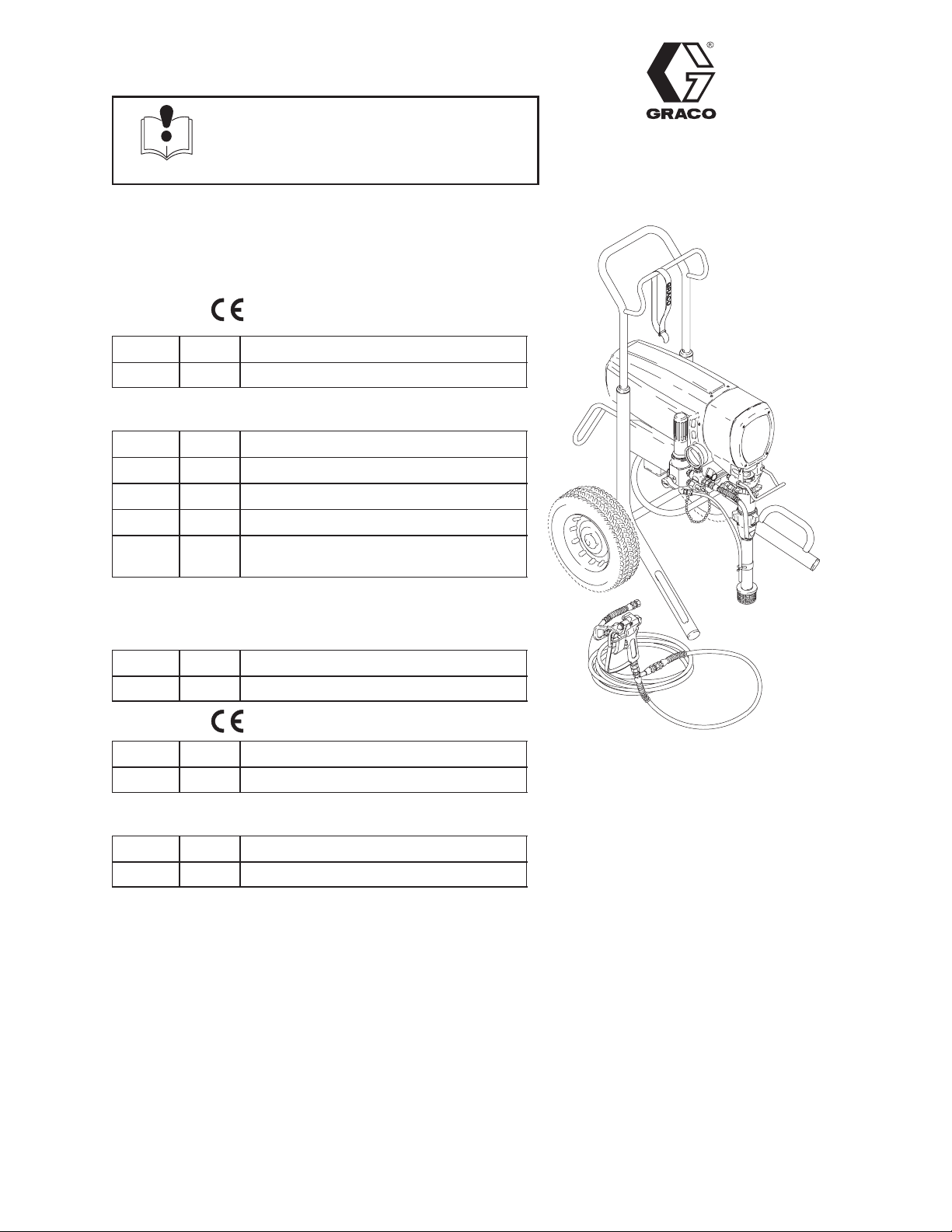
Airless Paint Sprayers
3000 psi (210 bar, 21 MPa ) Maximum Working Pressure
ULTRAMAX 1595
230 VAC
Model Series Description
232164 A Hi-boy with RAC IV tip, gun and hose
120 VAC
Model Series Description
232160 A Hi-Boy
232161 A Hi-Boy with RAC IV tip, gun and hose
232162 A CSA/UL Hi-Boy
232163 A CSA/UL Hi-Boy with RAC IV tip, gun
and hose
Rev. F
First choice when
quality counts.
MARK V
100 VAC
Model Series Description
232166 A Hi-Boy
230 VAC
Model Series Description
232173 A Hi-boy with RAC IV tip, gun and hose
120 VAC
Model Series Description
232171 A Hi-Boy with RAC IV tip, gun and hose
All models are not available in all countries
Table of Contents
Component Function and Identification 3. . . . . . . . . . . .
Troubleshooting 5. . . . . . . . . . . . . . . . . . . . . . . . . . . . . . . .
General Repair Information 4. . . . . . . . . . . . . . . . . . . . . .
Motor Brush Replacement 7. . . . . . . . . . . . . . . . . . . . . .
Pressure Control 9. . . . . . . . . . . . . . . . . . . . . . . . . . . . . . .
Pressure Control Repair 10. . . . . . . . . . . . . . . . . . . . . . .
Pressure Control Wiring 12. . . . . . . . . . . . . . . . . . . . . . . .
Motor Replacement 13. . . . . . . . . . . . . . . . . . . . . . . . . . . .
Bearing Housing & Connecting Rod Replacement 14.
8194A
Model 232164
Related Manuals
Operator 308855. . . . . . . . . . . . . . . . . . . . . . . . . . .
Displacement Pump 308798. . . . . . . . . . . . . . . . .
Spray Gun 308491. . . . . . . . . . . . . . . . . . . . . . . . .
Spray Tip 308644. . . . . . . . . . . . . . . . . . . . . . . . . . .
Drive Housing Replacement 15. . . . . . . . . . . . . . . . . . . .
Displacement Pump Repair 16. . . . . . . . . . . . . . . . . . . . .
Parts 18. . . . . . . . . . . . . . . . . . . . . . . . . . . . . . . . . . . . . . . .
Accessories 23. . . . . . . . . . . . . . . . . . . . . . . . . . . . . . . . . .
Technical Data 23. . . . . . . . . . . . . . . . . . . . . . . . . . . . . . . .
Dimensions 23. . . . . . . . . . . . . . . . . . . . . . . . . . . . . . . . . . .
Graco Phone Number 24. . . . . . . . . . . . . . . . . . . . . . . . . .
Graco Warranty 24. . . . . . . . . . . . . . . . . . . . . . . . . . . . . . .
GRACO INC. P.O. BOX 1441 MINNEAPOLIS, MN 55440–1441
COPYRIGHT 1998, GRACO INC.
Graco Inc. is registered to I.S. EN ISO 9001
Page 2
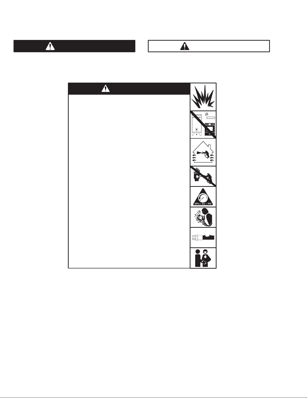
Warnings and Cautions
Warning Symbol
WARNING
This symbol alerts you to the possibility of serious
injury or death if you do not follow the instructions.
WARNING
Fire and explosion can occur when spraying or flushing
flammable fluid in an area where air circulation is poor and
flammable vapors can be ignited by an open flame or sparks.
To help prevent a fire and explosion:
Use outdoors or in an extremely well ventilated area.
Do not use 1,1,1–trichloroethane, methylene chloride, other
halogenated hydrocarbon solvents or fluids containing such
solvents in pressurized aluminum equipment. Such use could
result in a chemical reaction, with the possibility of explosion.
Remove, extinguish or unplug all ignition sources; tape wall
switches. Do not smoke in spray area.
Ground Sprayer, object being sprayed, paint and solvent pails.
Hold gun firmly to side of a grounded pail when triggering into pail.
Use a properly grounded outlet.
Use only conductive airless paint hose.
Do not modify this equipment.
Fluid injection is a serious injury! If high pressure fluid
pierces your skin, the injury might look like “just a cut”. But it is
a serious wound! Get immediate medical attention.
To help prevent injection, always:
Engage trigger safety latch when not spraying.
Point gun away from yourself or anyone else.
Relieve pressure before checking or repairing any leak.
Relieve pressure when you turn off the sprayer or stop
spraying
Keep drain hose outlet under fluid when opening drain valve.
Relieve pressure through the gun when you turn off the
sprayer or stop spraying.
Do not use components rated less than system Maximum
Working Pressure
Caution Symbol
CAUTION
This symbol alerts you to the possibility of damage to
or destruction of equipment if you do not follow the
instructions.
2 308854
Never allow children to use this unit. If you are injured using this
equipment, get immediate medical treatment.
Page 3
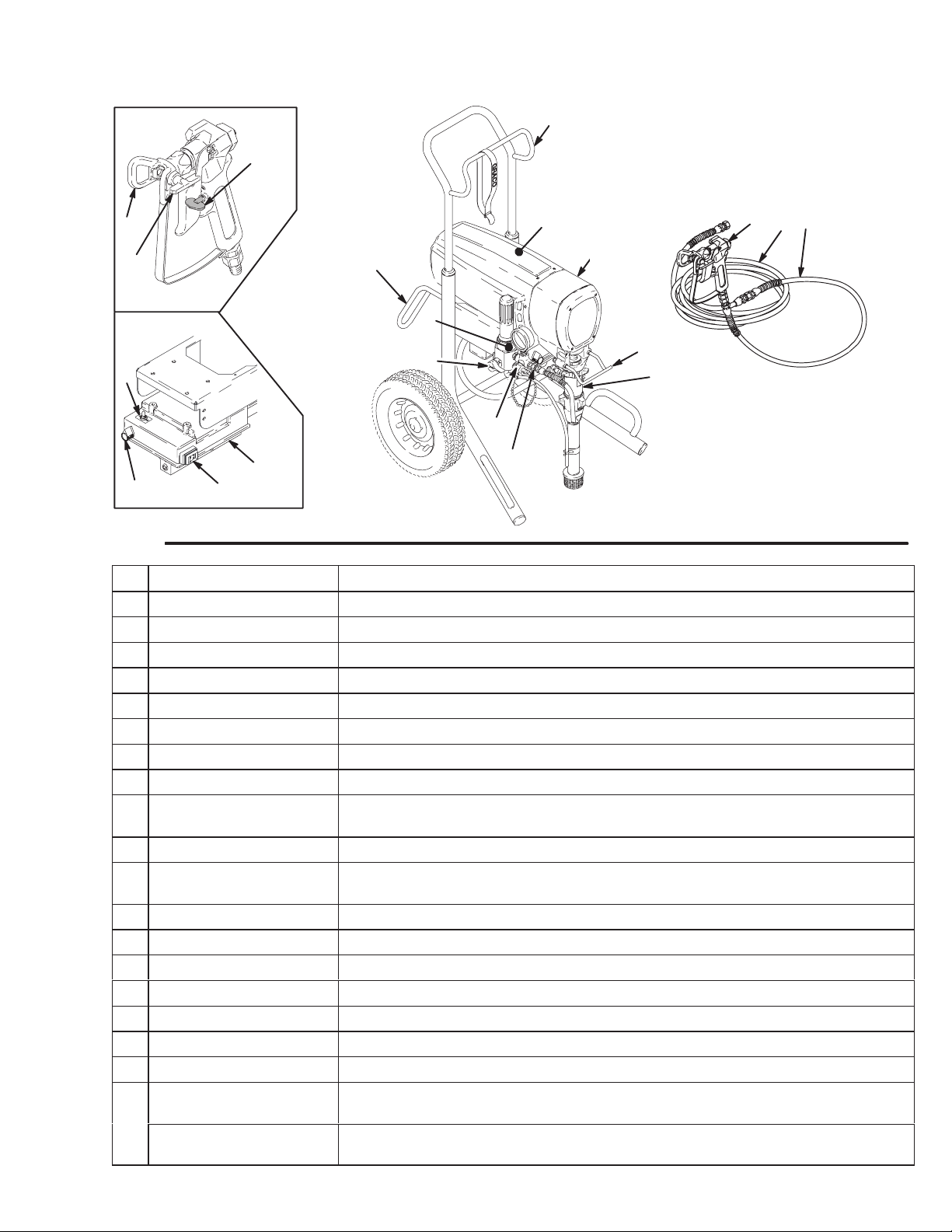
Component Identification and Function
V
T
S
R
03008
W
K
LJ
7148B
Fig. 1
A Motor DC motor, permanent magnet, totally enclosed, fan cooled
B Drive Assembly Transfers power from DC motor to the displacement pump
C Pail Hanger Container for fluid to be sprayed may be hung here
D Displacement Pump Transfers fluid to be sprayed from source through spray gun
E Primary Fluid Outlet Single spray gun operation is connected here
F Secondary Fluid Outlet Second spray gun operation is connected here
G Pressure Drain Valve Relieves fluid outlet pressure when open
H Fluid Filter Final filter of fluid between source and spray gun
J Pressure Adjust Knob Controls fluid outlet pressure
K Pressure Control Controls motor speed to maintain fluid outlet pressure at displacement pump
L ON/OFF Switch Power switch that controls VAC main power to sprayer
M 3 ft (0.9 m) Hose 3/16 in. ID, grounded, nylon hose used between 50 ft hose and spray gun to
N 50 ft (15 m) Main Hose 1/4 in. ID, (3/8 in. ID, MARK V) grounded, nylon hose, spring guards both ends
P Spray Gun High pressure spray gun with gun safety latch
R RAC IV Switch Tip Uses high pressure fluid to clear tip clogs without removing tip from spray gun
S RAC IV Tip Guard Reverse-A-Clean (RAC) tip guard reduces the risk of injection injury
T Spray Gun Safety Latch Gun safety latch inhibits accidental triggering of spray gun
U Power Cord Rack Holds wrapped power cord for storage
V Spray Hose Rack Holds wrapped spray hose for storage
W 10/12 Amp Switch Allows Models 232164, 232173 to operate on 10A service with reduced perfor-
15/20 Amp Switch Allows Models 232160 through 232163, 232166, 232171 to operate on 15A ser-
U
H
G
F
outlet. Works with pressure adjusting knob.
allow more flexibility when spraying
mance
vice with reduced performance
A
B
C
D
E
8194A
M
P
N
3308854
Page 4
General Repair Information
CAUTION
To reduce risk of pressure control malfunction:
Use needle nose pliers to disconnect a wire. Never
pull on wire, pull on connector.
Mate wire connectors properly. Center flat blade of
insulated male connector in female connector.
Route wires carefully to avoid interference with
other connections of pressure control. Do not pinch
wires between cover and control box.
Tool List
Phillips screwdriver
Small flat blade
screwdriver
Needle nose pliers
Plastic mallet or 20 oz
(max) hammer
12 in. adjustable wrench
Adjustable, open-end
wrench
Torque wrench
1. Keep all screws, nuts, washers, gaskets, and
electrical fittings removed during repair procedures. These parts are not normally provided with
replacement assemblies.
1/4 in. hex key wrench
3/16 in. hex key wrench
5/8 in. socket wrench
3/8 in. open end wrench
1/2 in. open end wrench
3/4 in. open end wrench
7/8 in. open end wrench
High quality motor oil
Bearing grease
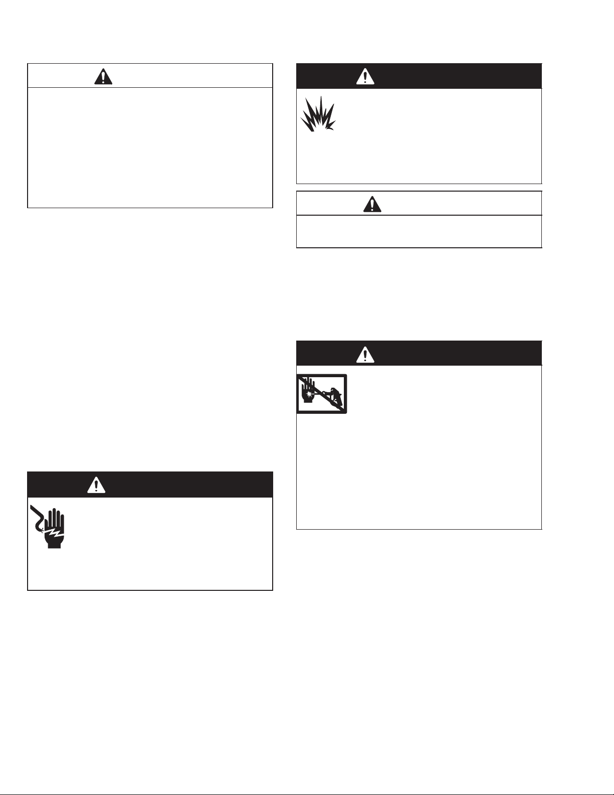
WARNING
ELECTRIC SHOCK HAZARD
To reduce risk of serious injury, including
electric shock, do not touch moving or
electrical parts with fingers or tools while
testing repair. Shut off and unplug sprayer when
inspection is complete. Install all covers, gaskets,
screws and washers before operating sprayer.
2. Test repair after problem is corrected.
3. If sprayer does not operate properly, review
repair procedure to verify procedure was done
correctly. If necessary, see Troubleshooting, page
5, for other possible solutions.
WARNING
EXPLOSION HAZARD
Motor and drive housing are very hot
during operation and could burn skin if
touched. Flammable materials spilled on
hot, bare motor could cause fire or explosion. Have
motor shield in place during operation to reduce
risk of burns, fire or explosion.
CAUTION
Do not run sprayer dry for more than 30 seconds to
avoid damaging pump packings.
4. Install motor shield before operation of sprayer
and replace if damaged. Motor shield directs
cooling air around motor to prevent overheating. It
can also reduce risk of burns, fire or explosion; see
preceding WARNING.
Pressure Relief Procedure
WARNING
INJECTION HAZARD
System pressure must be manually
relieved to prevent system from starting
or spraying accidentally. Fluid under high
pressure can be injected through skin and cause
serious injury. To reduce risk of injury from injection, splashing fluid, or moving parts, follow Pres-
sure Relief Procedure whenever you:
are instructed to relieve pressure,
stop spraying,
check or service any system equipment,
or install or clean spray tip.
1. Lock gun safety latch.
2. Turn ON/OFF switch to OFF.
3. Unplug power supply cord.
4. Unlock gun safety latch. Hold metal part of gun
firmly to grounded metal pail. Trigger gun to relieve
pressure.
5. Lock gun safety latch.
6. Open pressure drain valve. Leave pressure drain
valve open until ready to spray again.
If suspected that spray tip or hose is completely
clogged, or that pressure has not been fully relieved
after following steps above, VERY SLOWLY loosen tip
guard retaining nut or hose end coupling to relieve
pressure gradually, then loosen completely. Now clear
tip or hose obstruction.
4 308854
Page 5

Troubleshooting
TYPE OF PROBLEM WHAT TO CHECK
Motor runs and pump strokes,
but output is low or there is no
output.
If check is OK, go to next check
Extension cord size and length. Replace cord with a larger size, grounding
Paint supply. Refill and reprime pump.
Clogged intake strainer. Remove and clean strainer and reinstall. Mark
Loose suction tube or loose fittings. Tighten; use thread sealant or sealing tape on
Worn spray tip. Follow Pressure Relief Procedure
Motor brushes, loose leads and terminals,
minimum 13 mm brush length, broken or
misaligned springs, or brushes binding in
holders. See page 7.
Motor armature for shorts. Use an armature
tester (growler).
If pump continues to stroke when gun trigger
is released. With pump on and primed, trigger
gun momentarily, then release and engage
safety latch. Relieve pressure, turn off and
unplug sprayer.
WHAT TO DO
When check is not OK refer to this column
type extension cord.
V models 232171 and 232173 strainer is for
use in paint only.
threads, if necessary.
Warning, then replace tip. See your
separate gun or tip manual.
Replace parts as needed. See page 7.
Replace motor. See page 13.
Service pump. See manual 308798.
If intake valve ball and piston ball are seating
properly.
Intake valve ball is packed with material. Remove and clean intake valve. Do not
Leaking around throat packing nut which may
indicated worn or damaged packings.
Defective pressure control transducer. Replace pressure control transducer. See
Remove intake valve and clean. Check balls
and seats for nicks; replace if necessary.
See manual 308798. Strain paint before
using to remove particles that could clog the
pump.
leave Mark V models 232171 and 232173
sprayers under pressure for more than 5
minutes when pumping texture material and
not actively spraying.
Replace packings. See manual 308798.
Also check piston valve seat for hardened
paint or nicks and replace if necessary.
Tighten the packing nut/wetcup.
page 10.
(Continued on page 6)
5308854
Page 6

Troubleshooting
Motor runs but pump does not
stroke.
Motor is hot and runs
intermittently.
Displacement pump connecting rod pin (20).
See page 16.
Frozen or hardened paint in the pump (39). Thaw. See NOTE 1. Plug in sprayer and turn
Be sure crank in drive housing rotates; plug
in sprayer and turn on briefly to check. Turn
off and unplug sprayer.
Determine if sprayer was operated at high
pressure with small tips, which causes low
motor RPM and excessive heat build up.
Be sure ambient temperature where sprayer
is located is no more than 90
is not located in direct sun.
Determine if sprayer was turned on,
pressurized, but not operating for long
periods of time.
F and sprayer
Replace pin, if missing. Be sure retainer
spring (35) is fully in groove all around
connecting rod. See page 16.
on. Slowly increase pressure setting to see if
motor starts.
Check drive housing assembly for damage
and replace if necessary. See page 17.
Decrease pressure setting or increase tip
size.
Move sprayer to shaded, cooler area, if
possible.
Turn off sprayer whenever you stop spraying
for a while and relieve fluid pressure.
NOTE 1: Thaw sprayer in a warm area if water or water-based paint has frozen in it. Do not start sprayer until it has
thawed completely. If paint hardened (dried) in sprayer, replace pump packings. See manual 308798.
6 308854
Page 7
Grounding
Grounding
WARNING
Improper installation or alteration of the grounding
plug will result in a risk of electric shock, fire or
explosion that could cause serious injury or death.
1. Models 232160 through 233163, 232171 require a
120 Vac, 60 Hz, 10A circuit with a grounding
receptacle. Models 232164, 232173 requires a 230
Vac, 50 Hz, 10A circuit with a grounding receptacle. Model 232166 requires a 100 Vac, 50 Hz,
15A circuit with a grounding receptacle. See Fig. 2.
Motor Brush Replacement
NOTE: Replace brushes worn to less than 1/2 in.
Brushes wear differently on each side of motor, check both sides. Brush Repair Kit 222157
is available for Models 232164, 232173 and
Brush Repair Kit 220853 is available for Models 232160 through 232163, 232166, 232171.
Spring clip, 110816, may be purchased separately.
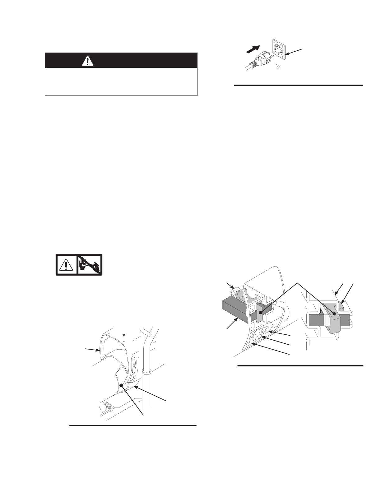
Motor Brush Removal
Grounded
Outlet
Fig. 2
2. Do not alter ground prong or use adapter.
3. A 1.5 mm
with this equipment.
4. Fig. 4. Push in 110816 spring clip (A) to release
hooks (B) from brush holder (C). Pull out spring
clip.
5. Fig. 4. Loosen terminal screw (D). Pull brush lead
(E) away, leaving motor lead (F) in place. Remove
brush (G) and spring (H).
Model 232164
2
by 90 m extension cord may be used
9286A
1. Read General Repair Information; page 4.
2.
3. Fig. 3. Remove motor shield (14). Remove inspection covers (B) and gaskets on each side of
motor.
14
Fig. 3
Relieve pressure; page 4.
(Continued on page 8)
A
B
7703B
H
G
Fig. 4
6. Inspect commutator for excessive pitting, burning
or gouging. A black color on commutator is normal.
Have commutator resurfaced by a qualified motor
repair shop if brushes wear too fast.
A
E
D
F
BC
01227
7308854
Page 8
Motor Brush Replacement
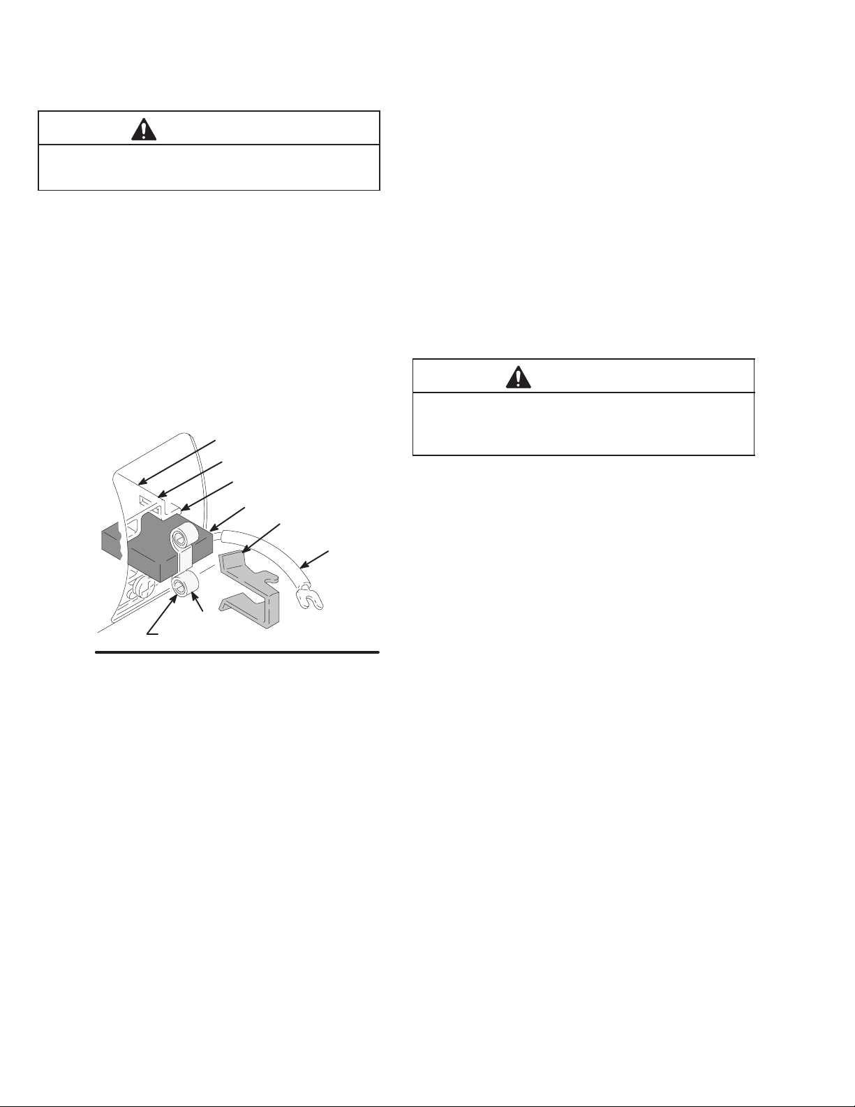
Motor Brush Installation
CAUTION
When installing brushes, follow all steps carefully to
avoid damaging parts.
7. Fig. 5. Install new brush (G) with lead in long slot
(J) of brush holder (C).
8. Fig. 4. Slide brush lead (E) under washer of terminal screw (D) and tighten screw. Be sure motor
lead (F) is connected at terminal screw.
9. Fig. 5.Place spring (H) on brush (G).
10. Fig. 5. Install spring clip (A). Push down to hook
short slots (K) in brush holder (C).
C
K
J
G
A
11. Repeat for other side.
12. Test brushes.
a. Remove pump connecting rod pin.
b. With sprayer OFF, turn pressure control knob
fully counterclockwise to minimum pressure.
Plug in sprayer.
c. Turn sprayer ON. Slowly increase pressure
until motor is at full speed.
CAUTION
Do not run sprayer dry for more than 30 seconds
while checking brushes to avoid damaging displacement pump packings.
13. Install brush inspection covers and gaskets.
14. Break in brushes.
Fig. 5
H
NOTE SPRING COIL DIRECTION
E
01227
a. Operate sprayer 1 hour with no load.
b. Install connecting rod pin.
8 308854
Page 9

Pressure Control
CAUTION
8. Install pump pin and fan cover.
Do not install the pressure control until motor is
checked. A defective motor may damage the pressure control. Make sure to test the motor prior to
pressure control installation.
WARNING
ELECTRIC SHOCK HAZARD
To reduce the risk of Electric Shock: wait
5 minutes after turning sprayer off before
servicing to allow stored current to dis-
charge.
Motor Test
With motor shield off and four motor leads disconnected:
1. Check continuity with multimeter from each black
motor lead to ground (one at a time). Any reading
less than infinite resistance – even very high resistance – means motor is shorted to ground. Replace motor.
Pressure Control Replacement
1.
2. Remove two screws (19) holding filter
assembly (A). See Fig. 7 and parts list, except as
noted.
3. Remove filter assembly by unthreading swivel
union (15) from hex nipple (102). Unthread nipple
from pressure control (5)
4. Remove 8 screws (64) and motor shield (14).
5. Remove outlet cover (221) on pressure control
wiring box. Disconnect motor leads. See Fig 6.
6. Loosen electrical tubing (22) from pressure control
fitting and pull out wires
7. Remove hose (28) from rear of pressure
control swivel union (15).
Relieve pressure; page 4.
CAUTION
A motor that is shorted to ground will damage the
pressure control.
2. Remove fan cover from motor.
3. Remove pump pin ( See page 16 for instructions to
remove pin).
4. With black motor leads not connected, use motor
fan to spin motor quickly. Motor should spin freely
in both directions. If not, replace motor.
5. Connect black motor leads together.
6. Use motor fan to turn motor. It should be much
harder to turn than in step 4. If there is uneven or
no resistance to turning, check brushes and replace if necessary.
7. If there is still uneven or no resistance to turning,
replace motor.
8. Support pressure control (5) and carefully remove
motor mount screws (37). Remove pressure
control.
9. Install new pressure control (5) with screws (37).
10. Continue to assemble sprayer.
Black
Fig 6
Red
Yellow
Black/White
Black
7145A
9308854
Page 10

Pressure Control
22,85
1
15
28
1 Seals (85) located inside conduit (22)
Fig 7
64
06964A
37
19
5
221
A
102
ULTRAMAX 1595 shown
Pressure Control Repair
14
8184A
General Repair and Replacement
1.
2. Remove power cord (90) and plug retainer (89) by
removing screws (230) and washers (229).
3. Remove screws (213) and lockwashers (214).
Carefully remove control housing (202) from
control motor board (201) so internal wiring is not
damaged. Lay housing on side next to control
motor board. See Fig. 8 and parts list.
4. Remove and replace only those components and
wires necessary for repair. Make a diagram showing wire hook–ups for items removed to insure
correct wiring when reinstalling. See Fig 9 for
wiring information.
5. Install control housing (202) to motor control
board (201) using screws (213) and
lockwashers (214).
Relieve pressure; page 4.
Pressure Control Transducer and O–Ring
Replacement
WARNING
FIRE AND EXPLOSION HAZARD
Proper o–ring replacement is essential
to reduce the risk of fire or explosion
which can result in serious injury and
property damage.
NOTE: Do not replace o–ring unless damaged or if
leakage is seen around weep hole, o–ring or
transducer.
1. See Fig. 8 and pressure control part list. Disassemble pressure control as in steps 1 through 4 on
page 10 and remove old transducer (219) and, if
necessary, old o–ring (220).
10 308854
Page 11
Pressure Control Repair
229
202
214
216
218
217
219
220
A
213
215
230
90 REF
89 REF
1
213
B
Torque to 150 in–lb (17 N.m)
1
Fig 8
2. Carefully slide new o–ring (220) down bore (A) of
motor control (201) into o–ring groove (B). Make
sure o–ring is in groove around its entire circumference.
NOTE: PTFEo–ring (220) is stiffer than a rubber
o–ring and may be difficult to place in groove.
214
C
201
8185A
5. Carefully remove transducer and verify that o–ring
is seated correctly and not pushed out of groove. If
not seated correctly use new o–ring and repeat
steps 2 through 5.
6. When o–ring is correctly installed, reinstall transducer and tighten screws to 150 in-lb (17 Nm).
Install spacer (216) and C-clip (215). Connect
electrical lead and assemble sprayer.
3. Carefully slide new transducer and plastic
spacer (217) down bore. Loosely attach
bracket (218), screws (213), and washers (214).
4. Seat transducer into o–ring by drawing down
screws and washers until bracket is flush with
motor control surface.
7. Perform Flush and Prime procedures in STARTUP
of Operation Manual 308855 with compatible fluid.
8. Inspect weep hole (C) for any leakage.
9. If any leakage is present, replace o–ring repeating
steps 1 through 9.
11308854
Page 12

Pressure Control Wiring
GRN/YEL wire, E to housing ground
ON/OFF sw
WHITE wire
ON/OFF
SW–5 to
L2 on board
BLACK wire
ON/OFF
SW–2 to
L1 on board
Twisted pair
64
1253
Twisted pair
To J 3
Housing ground
L
E
N
BLACK wire, L to on/off sw–1
WHITE wire, N to on/off sw–4
Red wires to I1
and I2 on board
Twisted pair
7369C
From control housing,
one red wire to I1
From control housing,
one red wire to I2
Connector from
potentiometer to J3
Twisted pair
Wires J4/J5 to
10/12 switch
I1
I2
J3
J5 J4
J6
Connector from pressure
transducer to J6
L2
From control
housing, WHITE
wire to L2
From control
housing, BLACK
wire to L1
L1
J7
GND
Ground wire to
housing ground
7135B
Fig 9
12 308854
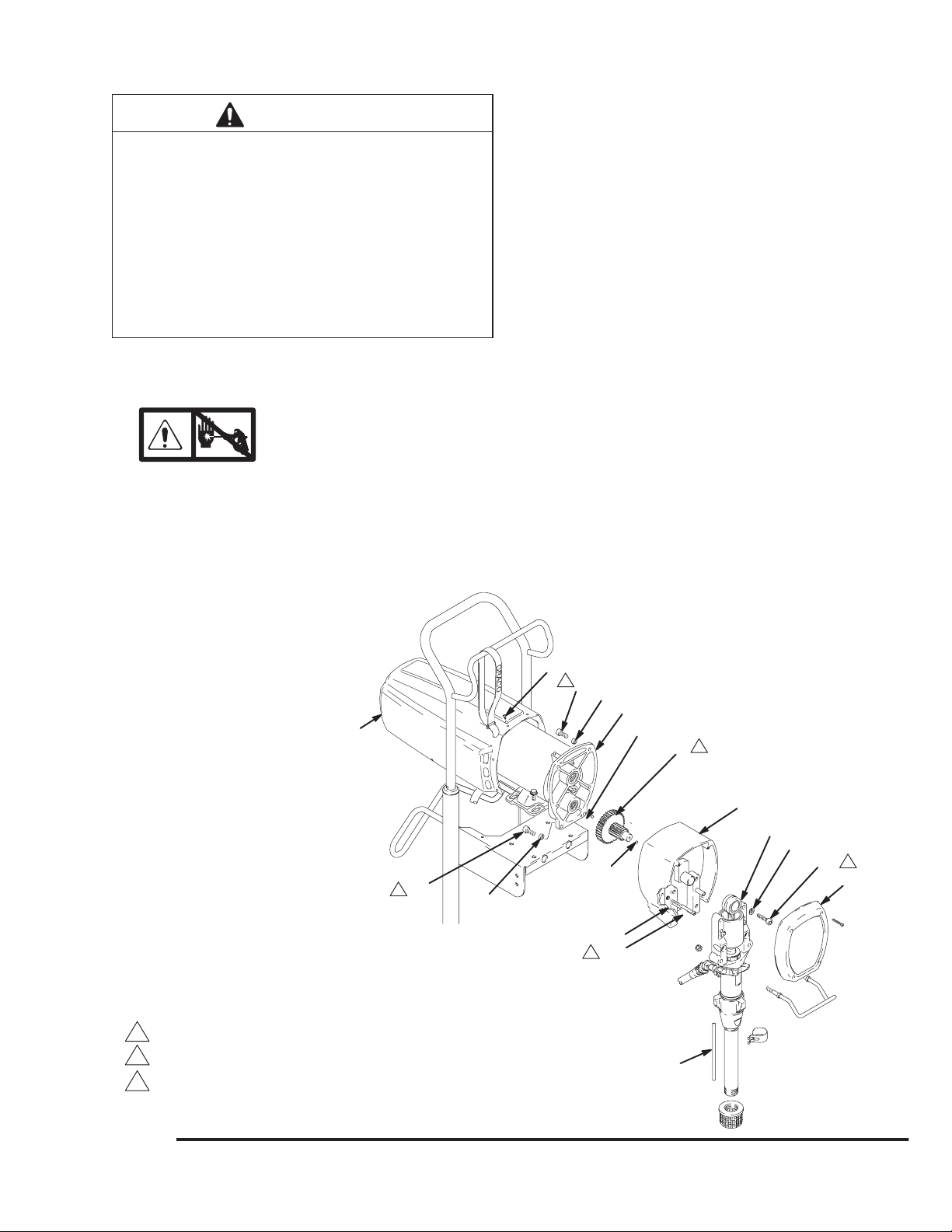
Page 13

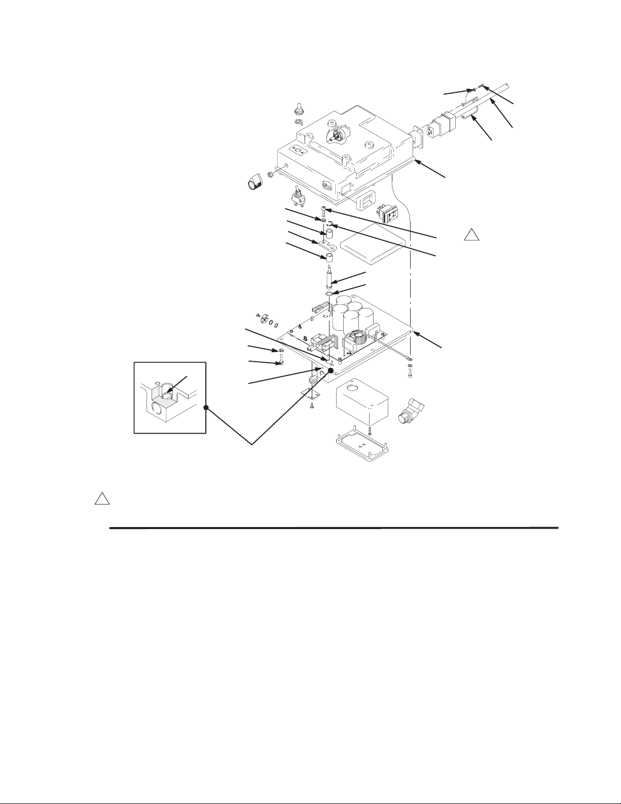
Motor Replacement
WARNING
ELECTRIC SHOCK HAZARD
To reduce the risk of Electric Shock: wait
5 minutes after turning sprayer off before
servicing to allow stored current to dis-
charge.
NOTE: Refer to Fig. 10 and parts list, except as
noted.
1.
2. Remove motor shield (14). Remove front cover
(31). Disconnect hose (28) at pump. Disconnect
drain hose (79) from pump (39).
3. Remove outlet cover on pressure control wiring
box. Disconnect four motor leads. See Fig 6.
4. Unscrew conduit connector (16) from motor and
pull motor leads from tubing (22).
5. Remove screws (33) from recess of drive housing.
6. Remove screws (21 and 30) from motor bell (F).
7. Use a plastic mallet to tap displacement pump (39)
from rear to loosen drive housing (18) from motor
bell (F). Pull off drive housing.
Relieve pressure; page 4.
CAUTION
DO NOT drop gear cluster (9) when removing drive
housing (18). The gear cluster may stay engaged in
the motor front end bell or the drive housing.
DO NOT lose thrust balls (10) located at each end of
gear cluster (9) or drop them between gears. The
balls, which are heavily covered with grease, usually
stay in the shaft recesses, but could be dislodged. If
caught between gears and not removed, the balls will
seriously damage the drive housing. If the balls are
not in place, the bearings will wear prematurely.
8. Lower pressure control (5) by unscrewing motor
mounting screws (37).
9. Lift off motor (1).
10. Mount and center new motor on frame and attach
pressure control (5) with motor mounting screws
(37).
11. Insert motor leads through connector (16) and
tubing (22) to pressure control. Screw connector
(125) two or three threads into motor. Tighten
locknut up to motor. Connect four motor leads.
See Fig. 6.
12. Liberally grease gear cluster (9) and pinion gear
(G) and pack all bearings in motor bell. Be sure
thrust balls (10) are in place. (One ball is included
with a replacement drive housing.)
13. Align gears and push drive housing (18) straight
onto motor bell (F) and locating pins.
14. Continue to reassemble sprayer.
Fig. 10
14
1
21
F
G
28
10
2
9
10
5
79
18
39
33
31
ULTRAMAX 1595 shown
12Seals (93) located inside conduit (22)
Apply 6 ounces bearing grease
7957A
37
16
22
1
30
13308854
Page 14
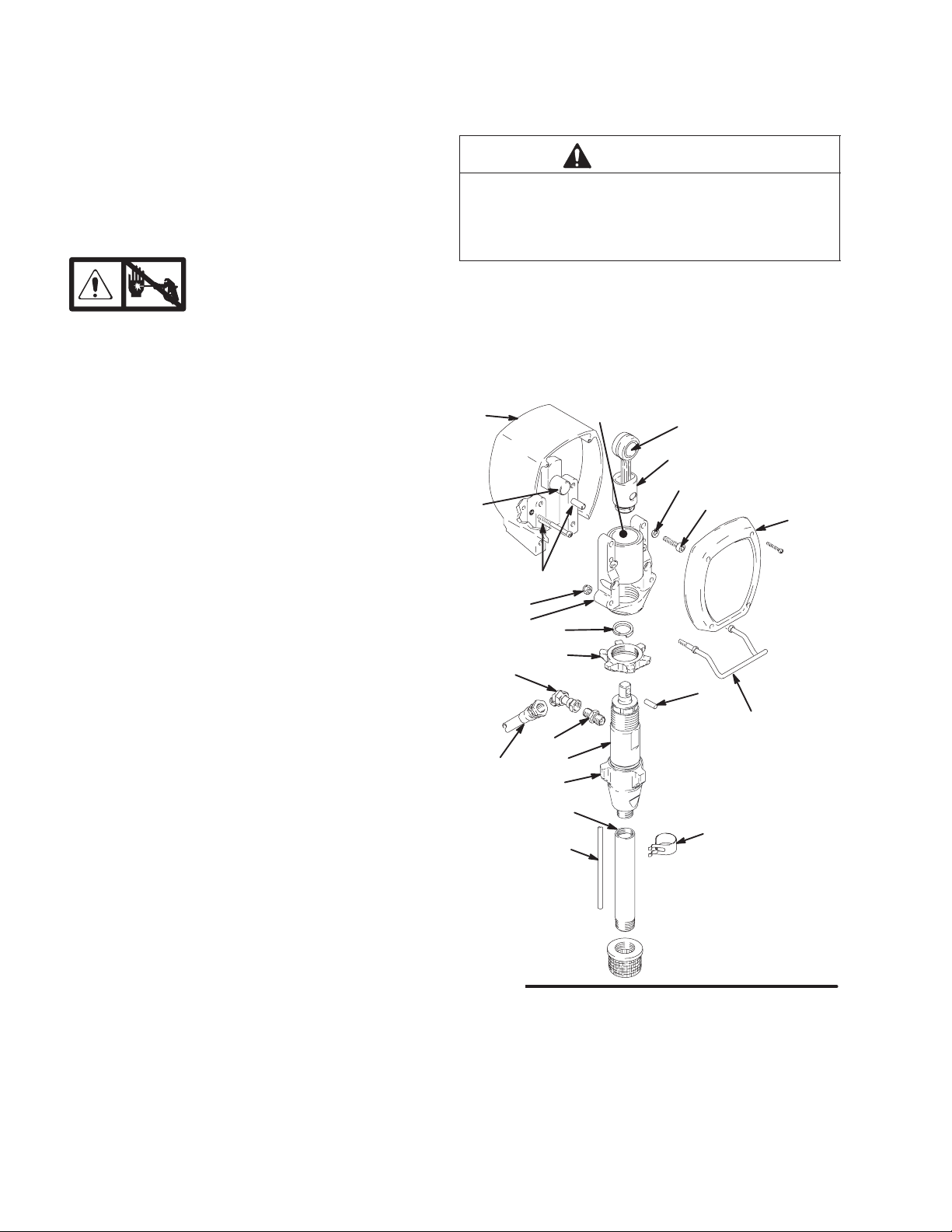
Bearing Housing and Connecting Rod
Replacement
NOTE: Read General Repair Information on page 4
before doing this procedure. See Fig. 11.
NOTE: Stop sprayer at bottom of its stroke to get crank
(E) in its lowest position.To lower crank manually, carefully rotate blades of fan with a screwdriver.
CAUTION
DO NOT use the bearing housing screws (33) to try
to align or seat the bearing housing; the bearing and
drive housing will not align properly and will result in
premature bearing wear.
1.
2. Remove front cover (31). Unclip drain hose (79)
from pump. Hold a wrench on pump intake valve
(H) and unscrew pump suction tube (42). Disconnect pump hose (28).
3. Push up retaining spring (35). Push pin (20) out
rear.
4. Loosen locknut (38). Unscrew displacement
pump (39).
5. Remove four screws (33) and lockwashers (49).
6. Lightly tap lower rear of bearing housing (27) with
a plastic mallet to loosen it from drive housing (18).
Pull bearing housing and connecting rod assembly
(29) straight off drive housing.
7. Remove pail bracket assembly (F) and install with
locknuts (13) on new bearing housing.
8. Inspect crank (E) for excessive wear and replace
parts as needed. Evenly lubricate inside of bronze
bearing (B) with high quality motor oil. Liberally
pack roller bearing (C) with bearing grease.
Relieve pressure; page 4.
12. Install screws (33) and lockwashers (49). Tighten
screws evenly to 300 in-lb (34 N.m).
13. Install pump. See page 17.
14. Install remaining parts. See Fig. 11.
B
35
38
39
OIL
H
PACK WITH
C
BEARING GREASE
29
49
TORQUE TO
300 in-lb (34 N.m)
33
20
31
F
18
E
G
13
27
25
101
28
9. Assemble connecting rod (29) and bearing
housing (27).
10. Clean mating surfaces of bearing (27) and
drive (18) housings.
11. Align connecting rod (29) with crank (E) and drive
housing locating pins (G) with bearing housing (27)
holes. Push bearing housing onto drive housing or
tap it into place with a plastic mallet.
14 308854
42
86
79
ULTRAMAX 1595 shown
7955A
Fig. 11
Page 15
Drive Housing Replacement
CAUTION
DO NOT drop gear cluster (9) when removing drive
housing (18). Gear cluster may stay engaged in the
motor front end bell or the drive housing.
DO NOT lose thrust balls (10) located at each end of
gear cluster (9) or drop them between gears. The
balls, which are heavily covered with grease, usually
stay in the shaft recesses, but could be dislodged. If
caught between gears and not removed, the balls will
seriously damage drive housing. If the balls are not
in place, the bearings will wear prematurely.
NOTE: Read General Repair Information on page 4
before doing this procedure. See Fig. 12.
1.
Relieve pressure; page 4.
4. Lightly tap lower rear of bearing housing (27) with
a plastic mallet to loosen it from drive housing (18).
Pull assembled bearing housing and connecting
rod straight off drive housing.
5. Remove two drive housing screws (51) and
lockwashers (63).
6. Remove two lower screws (30) and lockwashers
(63) and then two upper screws (21) and lockwashers (63) from front of motor (1).
7. Tap drive housing (18) with a plastic mallet to
loosen it from front of motor (1), and then pull drive
housing straight off.
8. Liberally apply approximately 4 ounces of bearing
grease to gear cluster (9). Grease is supplied with
drive housing replacement kit. Be sure thrust balls
(10) are in place.
2. Remove front cover (31) and motor shield (14).
Unclip drain hose (79) from pump.
3. Remove four bearing housing screws (33) and
lockwashers (49).
14
30
2
63
9. Align gears and push new drive housing straight
onto front of motor and locating pins.
10. Continue reassembling sprayer.
64
2
21
63
1
10
3
9
18
27
49
1
10
33
31
Torque to 300 in-lb (34 N.m)
1
2
Torque to 90–100 in-lb (10.2–11.3 N.m)
3
Liberally apply grease
Fig. 12
63
2
51
ULTRAMAX 1595 shown
79
7956A
15308854
Page 16

Removing pump
Displacement Pump Repair
1. Flush pump. Relieve pressure. Fig. 13. Cycle
pump with piston rod (A) in its lowest position.
2. Fig. 13. Unscrew suction tube and hose from
pump.
A
Fig. 13
3. Fig. 14. Use screwdriver to push retaining spring
(35) up and pin (20) out.
7672A
4. Fig. 15. Loosen locknut by hitting firmly with a
20 oz (maximum) hammer. Unscrew pump.
Fig. 15
7673A
Repairing Pump
See manual 308798 for pump repair instructions.
Fig. 14
35
20
7674A
16 308854
Page 17

Displacement Pump Repair
Installing pump
WARNING
If the pin works loose, it or other parts could break
off due to the force of the pumping action. These
parts could be projected through the air and result
in serious bodily injury or property damage, including damage to the pump, connecting rod or bearing
housing.
CAUTION
3. Fig. 18. Push retaining spring (35) into groove all
the way around connecting rod.
If the pump locknut loosens during operation, the
threads of the bearing housing will be damaged.
1. Fig. 16. Pull piston rod out 1.5 in. Screw in pump
until holes in bearing cross link and piston rod
align.
7676A
Fig. 16
35
Fig. 18
Fig. 19. Screw jam nut down onto pump until stops.
Screw pump up into bearing housing until it is stopped
by jam nut. Back off pump and jam nut to align pump
outlet to back. Tighten jam nut by hand, then tap 1/8 to
1/4 turn with a 20 oz (maximum) hammer to approximately 75" 5 ft–lb (102 Nm).
7674A
2. Fig. 17. Push pin (20) into holes.
Fig. 17
7675A
20
Fig. 19
Fig. 20. Fill packing nut with Graco TSL, through one
of the slits, until fluid flows onto the top of seal.
Fig. 20
7673A
7677A
17308854
Page 18

Parts Drawing – Sprayer
,
Models 232160 through 232164, 232166, Series A
82
74
90
REF
61
62
17
83
52
80
REF
6
89
81
64
14
61
55
104
A
A
110
88
Detail B
59
37
30
44
10
9
64
77
63
19
48
69
10
21
1
5
237 REF
18
63
51
25
28
79 REF
35
13
101
29
27
20
39
50
38
42
49
33
86
15
31
32
73
16
22
54
28
Detail A–A
26
58
11
95
18 308854
47
92
19
75
34
60
36
93
94
72
103
41
79
56
15
57
43
71
98
53
99
102
96
97
57
6
8
24
Detail B
107
105
106
7951A
Page 19

Parts List – Sprayer
Models 232160 through 232164, 232166, Series A
REF
NO. PART NO. DESCRIPTION QTY
1 MOTOR, ELECTRIC 1
includes 41 and 73a
235726* Model 232164 1
220854* Models 232160 thru 232163 1
5 PRESSURE CONTROL 1
see parts list on page 23
239429 Model 232164 1
239750 Models 232160 thru 232163 1
6 240143 FRAME, cart 1
8 107266 TERMINAL 2
9 220637 GEAR REDUCER 1
10 100069 BALL 2
11 104811 CAP, hub 2
13 112746 LOCKNUT, 5/16 –18 2
14 240483 SHIELD, motor (includes label 77) 1
15 155494 UNION, swivel, 90 2
16 110138 CONNECTOR, conduct 1
17 112827 BUTTON, snap 2
18 220879 DRIVE HOUSING 1
19 114402 SCREW, hex hd, flanged 4
20 183210 PIN, straight, hdls 1
21 100644 SCREW, cap 2
22 065312 TUBING, electrical, flexible, 5.5 in. 1
24 107264 TERMINAL 2
25 161889 UNION, swivel 1
26 154636 WASHER 2
27 240701 BEARING HOUSING 1
28 240246 HOSE, coupled, 1/4in. by 20 in. 1
29 220640 ROD CONNECTING KIT 1
30 100643 SCREW, cap 2
31 188423 COVER, housing 1
32 108850 SCREW, mach, filh 4
33 110141 SCREW, cap, sch 4
34 193081 BRACKET, manifold, filter 1
35 183169 SPRING, retaining 1
36 111699 GASKET, seat, valve 1
37 110963 SCREW, flange, hex hd 4
38 193031 NUT, retaining 1
39 240291 KIT, pump, displacement 1
manual 308798
41 112538 ELBOW, 90, street, reducing 1
42 193097 TUBE, suction 1
43 PLUG, packless
240131 Models 232160 thru 232164, 1/4 in. 1
240987 Model 232166, 3/8 in. 1
44 114271 STRAP, retaining 1
47 206994 THROAT SEAL LIQUID, 8 OZ 1
48 240315 BOWL, filter 1
49 106115 WASHER, lock, spring 4
50 181072 STRAINER, inlet 1
51 108849 SCREW, cap, sch 2
52 110243 RING, retaining 2
53 108691 PLUG, tubing 2
54 108460 CONNECTOR, conduit, 45 1
55 LABEL, caution 1
192839 English 1
193521 Japanese 1
56 104361 PACKING, o–ring 1
57 ADAPTER
164672 Models 232160 thru 232164, 2
3/8 npt x 1/4 npsm
162485 Model 232166, 3/8 npt x 3/8 npsm 2
58 101242 RING, retaining, ext. 2
59 167025 STRAINER, 60 mesh 1
60 179811 WHEEL, semi–pneumatic 2
REF
NO. PART NO. DESCRIPTION QTY
61 240136 HANDLE, cart 1
62 192027 SLEEVE, cart 2
63 105510 WASHER, lock, spring 6
64 108865 SCREW, machine, pan hd 10
69 111482 RIVET, snap 1
71 171941 SPRING, compression 1
72 186075 SUPPORT, filter 1
73 192719 HANGER, pail 1
74 100020 CONNECTOR, tube, female 2
75 187615 VALVE, seat 1
77 LABEL, DANGER 1
187791 English 1
189702 Japanese 1
79 240144 HOSE, drain 1
80 109032 SCREW, machine, pan hd 4
81 185384 BRACKET 2
82 110240 NUT, self–retaining 2
83 183350 WASHER 2
85 107447 SEAL, conduit 2
86 192691 CLIP, spring 1
87 290447 LABEL, warning 3
(on brush covers–not shown)
88 187784 LABEL, danger, French 1
89 192149 RETAINER, plug 1
90 CORD SET 1
240539 European 1
240540 Italy 1
240541 Denmark 1
240542 Switzerland 1
240543 Bare end, European 1
240247 Japan 1
92 235014 DRAIN VALVE ASSEMBLY 1
93 224807 CAM, drain valve 1
94 111600 PIN, grooved 1
95 187625 HANDLE, valve, drain 1
96 102814 GAUGE, pressure, fluid 1
97 100176 BUSHING, hex 1
98 156849 NIPPLE, pipe 1
99 100483 TEE, pipe 1
101 162485 NIPPLE, adapter 1
102 193024 NIPPLE, hex 1
103 240700 HOUSING KIT, filter (includes item 56) 1
104 192839 LABEL, warning, French 1
105 238361 HOSE, grounded, nylon, 1/4” ID, 1
cpld 1/4 npsm(f), 50 ft (15m)
spring guards both ends
106 238358 HOSE, grounded, nylon, 3/16” ID, 1
cpld 1/4 npsm(f), 3 ft (.9 m)
spring guards both ends
107 222667 GUN, contractor, basic 1
manual 307614
108 221621 TIP, spray, cylinder (not shown) 1
manual 308644
109 237859 GUARD, rac (not shown) 1
110 LABEL, WARNING 1
187975 English 1
193520 Japanese 1
Extra Danger and Warning tags and labels available free.
*Motor Brush Repair Kit is available:
Model 232164; order 222157
Models 232160 thru 232163, 232166; order 220853
Models 232160 and 232162 have items 88 & 104, but not 105
thru 107. Model 232166 does not nave any of these items.
19308854
Page 20

Parts Drawing – Sprayer
Models 232171, 232173; Series A
10
18
82
74
REF 61
62
17
83
52
80
REF 6
58
11
90
81
64
26
89
95
14
92
61
55
104
A
A
A
A
110
88
Detail B
60
19
34
75
97
36
59
72
103
37
30
19
56
15
48
44
57
64
71
77
63
53
9
21
69
63
63
1
79 REF
5
237 REF
6
102
96
99
42
25
51
35
13
10128
29
27
38
20
39
50
49
33
15
Detail B
Detail B
31
32
73
86
Detail A–A
Detail A–A
115
16
22
54,85
28 REF
8
24
106
47
20 308854
94
93
41
120
79
43
101
121
105
107
119
9001C
Page 21

Parts List – Sprayer
Models 232171, 232173; Series A
REF
NO. PART NO. DESCRIPTION QTY
REF
NO. PART NO. DESCRIPTION QTY
1 MOTOR, ELECTRIC 1
includes 41 and 73a
235726* Model 232173 1
220854* Model 232171 1
5 PRESSURE CONTROL 1
see parts list on page 23
239429 Model 232173 1
239750 Model 232171 1
6 240143 FRAME, cart 1
8 107266 TERMINAL 2
9 220637 GEAR REDUCER 1
10 100069 BALL 2
11 104811 CAP, hub 2
13 112746 LOCKNUT, 5/16 –18 2
14 240483 SHIELD, motor (includes label 77) 1
15 155494 UNION, swivel, 90 2
16 110138 CONNECTOR, conduct 1
17 112827 BUTTON, snap 2
18 220879 DRIVE HOUSING 1
19 114402 SCREW, hex hd, flanged 4
20 183210 PIN, straight, hdls 1
21 100644 SCREW, cap 2
22 065312 TUBING, electrical, flexible, 5.5 in. 1
24 107264 TERMINAL 2
25 161889 UNION, swivel 1
26 154636 WASHER 2
27 240701 BEARING HOUSING 1
28 240246 HOSE, coupled, 1/4in. by 20 in. 1
29 220640 ROD CONNECTING KIT 1
30 100643 SCREW, cap 2
31 188423 COVER, housing 1
32 108850 SCREW, mach, filh 4
33 110141 SCREW, cap, sch 4
34 193081 BRACKET, manifold, filter 1
35 183169 SPRING, retaining 1
36 193710 SEAL, valve 1
37 110963 SCREW, flange, hex hd 4
38 193031 NUT, retaining 1
39 240800 KIT, pump, displacement 1
manual 308798
41 100840 ELBOW, 90 1
42 241717 DEFLECTOR 1
43 240131 PLUG, packless 1
44 114271 STRAP, retaining 1
47 206994 THROAT SEAL LIQUID, 8 OZ 1
48 240315 BOWL, filter, includes 71 1
49 106115 WASHER, lock, spring 4
50 189920 STRAINER, inlet 1
51 108849 SCREW, cap, sch 2
52 110243 RING, retaining 2
53 108691 PLUG, tubing 2
54 108460 CONNECTOR, conduit, 45 1
55 LABEL, caution 1
192839 English 1
193521 Japanese 1
56 104361 PACKING, o–ring 1
57 164672 ADAPTER 1
58 101242 RING, retaining, ext. 2
59 167025 STRAINER, 60 mesh 1
60 179811 WHEEL, semi–pneumatic 2
61 240136 HANDLE, cart 1
62 192027 SLEEVE, cart 2
63 105510 WASHER, lock, spring 6
64 108865 SCREW, machine, pan hd 10
69 111482 RIVET, snap 1
71 171941 SPRING, compression 1
72 186075 SUPPORT, filter 1
73 192719 HANGER, pail 1
74 100020 WASHER, lock 2
75 193709 VALVE, seat 1
77 LABEL, DANGER 1
187791 English 1
189702 Japanese 1
79 194178 HOSE, drain 1
80 109032 SCREW, machine, pan hd 4
81 185384 BRACKET 2
82 110240 NUT, self–retaining 2
83 183350 WASHER 2
85 107447 SEAL, conduit 2
86 194525 CLIP, spring 1
87 290447 LABEL, warning 3
(on brush covers–not shown)
88 187784 LABEL, danger, French 1
89 114426 RETAINER, plug 1
90 CORD SET 1
114514 USA Models 232160, 232161, 232171 1
114515 CSA Models 232162, 232163 1
240539 European 1
240540 Italy 1
240541 Denmark 1
240542 Switzerland 1
240543 Bare end, European 1
92 240914 DRAIN VALVE ASSEMBLY 1
93 114708 SPRING 1
94 114688 NUT, capped 1
95 194102 HANDLE, valve, drain 1
96 102814 GAUGE, pressure, fluid 1
97 114797 GASKET 1
98 156849 NIPPLE, pipe 1
99 237475 SWIVEL, union 1
101 162485 NIPPLE, adapter 3
102 193024 NIPPLE, hex 1
103 194497 HOUSING, filter 1
104 192839 LABEL, warning, French 1
105 240797 HOSE, grounded, 3/8 in. x 50 ft (15m) 1
spring guards both ends
106 241735 HOSE, grounded, 1/4 x 3 ft (.9 m) 1
spring guards both ends
107 241338 GUN, texture; includes 105 and 106 1
manual 308491
110 LABEL, WARNING 1
187975 English 1
193520 Japanese 1
111 195119 LABEL, warning 1
(on drain hose–not shown)
115 159841 ADAPTER, 1/4 npt(f) x 3/8 npt(m) 1
119 224457 SWIVEL, straight 1
120 156971 NIPPLE 1
121 240987 PLUG, packless, 3/8 1
Extra Danger and Warning tags and labels available free.
* Motor Brush Repair Kit is available:
Model, 232173; order 222157
Model 232171; order 220853
Models 232171, 232173 have items, 105 thru 107.
Drain valve replacement kit 241276 is available
21308854
Page 22

Pressure Control Drawing
209
210
208
204
203
205
214
218
217
212
213
207
229
90 REF
230
228
89 REF
234
211
202
3
206
1
215
216
238
220
4
219
201
225
224
236
235
214
213
227
237
226
221
Torque to 150 in–lb (17 N·m)
1
To housing ground, Fig. 9.
2
Located this point, inside housing
3
WARNING! See Pressure Control Transducer and O–Ring Replacement on page 10 for correct replacement procedure.
4
222
Fig 21
232
233
231
2
54 REF
7202D
22 308854
Page 23

Pressure Control Parts List
Part Number 239750 or 239429
Ref
No. Part No. Description Qty
PRESSURE CONTROL 1
See Ref. No. 5 on page 21 for location
239750 Models 232160 through 232163, 1
232166
239429 Model 232164 1
201 MOTOR CONTROL BOARD 1
239283 Model 232164 1
239751 Models 232160 thru 232163, 166 1
202 CONTROL HOUSING 1
238976 Model 232164 1
239442 Models 232160 thru 232163, 166 1
203 111930 . SWITCH, toggle (10/12 or 15/20) 1
204 105658 . RING, locking 1
205 105659 . BOOT, toggle 1
206 111961 . SWITCH, rocker (on/off) 1
207 236352 . POTENTIOMETER (pressure adjust) 1
208 112382 . NUT, shaft sealing 1
209 114273 . KNOB, control 1
210 193072 . LABEL, control knob 1
211 192226 . SPACER, switch 1
212 112788 . SCREW, cap hd 2
213 100644 SCREW, cap 5
214 100016 WASHER, lock 5
215 114031 CLIP, cee 1
216 192223 SPACER, transducer 1
217 192144 SPACER, transducer 1
Replacement Danger and Warning labels, tags and cards are available at no cost.
These parts are included on all sprayers as shipped, but not on replacement pressure control 239576.
* These parts are included with replacement pressure control 239576, but are not on all sprayers as shipped.
Technical Data
Power Requirements
Models 232164 and 232173 230 VAC, 50 Hz,. . . . . . . . . . . .
Models 232160 thru 163, 232171 120 VAC, 60 Hz,. . . . . . . .
Model 232166 100 VAC, 50/60 Hz,. . . . . . . . . . . . . . . . . . . . .
Motor 1.6 HP. . . . . . . . . . . . . . . . . . . . . . . . . . . . . . . . . . . . . . . . .
Working Pressure Range 0–210 bar (0–21 MPa, 0–3000 psi)
Cycles/Gallon (liter) 118 (31). . . . . . . . . . . . . . . . . . . . . . . . . . . .
Maximum Delivery Rating 1.25 gpm (4.75 lpm). . . . . . . . . . . . .
Tip Size: one gun – 0.035; two guns – 0.025; three guns – 0.019
Power Cord
Model 232164. 232173 1.5 mm
Models 232160 – 163, 166, 171 2.0 mm
Inlet Paint Strainer 16 mesh (975 micron). . . . . . . . . . . . . . . . .
Outlet Paint Filter 60 mesh (238 micron). . . . . . . . . . . . . . . . . .
Pump Inlet Size 3/4 npt(m). . . . . . . . . . . . . . . . . . . . . . . . . . . . .
Fluid Outlet Size
Filter 3/8 npt(f). . . . . . . . . . . . . . . . . . . . . . . . . . . . . . . . . . . . . .
Filter with standard 3/8 npt(f) to 1/4 npsm adapter 1/4 npsm
Sound Data
Sound pressure level at one meter 85.3 db(A). . . . . . . . . . .
Sound power level 95.2 db(A). . . . . . . . . . . . . . . . . . . . . . . . .
Measured under maximum operating conditions per
ISO–3744
1 phase, 12A min or 5000W generator
1 phase, 15A min or 5000W generator
1 phase, 15A min or 5000W generator
with latex at 138 bar (13.8 MPa, 2000 psi)
with latex at 138 bar (13.8 MPa, 2000 psi )
2
by 4.5 m, 3 wire. . . . . . . .
2
by 4.5 m, 3 wire.
stainless steel screen, reusable
stainless steel screen, reusable
Ref
No. Part No. Description Qty
218 192145 BRACKET, transducer 1
219 236364 TRANSDUCER, pressure control 1
220 104319 O-RING See O-Ring Replacement 1
page 10
221 192050 ELECTRICAL ENCLOSURE KIT 1
222 M71503 SCREW 2
224 192142 PLUG 1
225 104836 SCREW 4
226 110637 SCREW 2
227 192155 COVER 1
228 113799 INLET, ac power 1
229 114027 WASHER, flat 2
230 111714 SCREW, machine, phillips, pan hd 2
231 189930 LABEL, caution 1
232 157021 WASHER, lock, internal 1
233 111593 SCREW, grounding 1
234 186620 LABEL, ground 1
235 111710 O-RING 1
236 111711 RING, backup 1
237 101754 PLUG, pipe 1
238 192212 PAD, foam 1
323* 235009 SWITCH TRANSDUCER (not shown) 1
324* 192150 BLOCK, transducer (not shown) 1
325* 108850 SCREW, machine, fil hd (not shown) 4
326* 111704 SCREW, machine, fil hd (not shown) 2
327* 239530 SWITCH (not shown) 1
Basic Sprayer Wetted Parts: zinc-plated carbon steel,. . . . . .
NOTE: Delrin
polyurethane, polyethylene, stainless steel, PTFE,
Delrin
, chrome plating, leather, V-Max UHMWPE,
aluminum, stainless steel, tungsten carbide
Dimensions
Weight (dry w/o packaging) 140 lb (63.5 kg). . . . . . . . . . . . . . .
Height 30.5 in. (775 mm). . . . . . . . . . . . . . . . . . . . . . . . . . . . . . .
Length 25.5 in. (648 mm). . . . . . . . . . . . . . . . . . . . . . . . . . . . . . .
Width 22.5 in. (572 mm). . . . . . . . . . . . . . . . . . . . . . . . . . . . . . . .
Accessories
DANGER LABELS
An English language DANGER label is on your sprayer.
If
you have painters who do not read English, order one of the following labels to apply to your
sprayer. Order labels from your Graco distributor.
Apply other
language here
French 187784
Spanish 185962
German 186042
Greek 186046
8183A
Korean 186050
23308854
Page 24

Graco Standard Warranty
Graco warrants all equipment referenced in this document which is manufactured by Graco and bearing its name to be free from
defects in material and workmanship on the date of sale by an authorized Graco distributor to the original purchaser for use. With the
exception of any special, extended, or limited warranty published by Graco, Graco will, for a period of twelve months from the date of
sale, repair or replace any part of the equipment determined by Graco to be defective. This warranty applies only when the equipment
is installed, operated and maintained in accordance with Graco’s written recommendations.
This warranty does not cover, and Graco shall not be liable for general wear and tear, or any malfunction, damage or wear caused by
faulty installation, misapplication, abrasion, corrosion, inadequate or improper maintenance, negligence, accident, tampering, or substitution of non–Graco component parts. Nor shall Graco be liable for malfunction, damage or wear caused by the incompatibility of
Graco equipment with structures, accessories, equipment or materials not supplied by Graco, or the improper design, manufacture,
installation, operation or maintenance of structures, accessories, equipment or materials not supplied by Graco.
This warranty is conditioned upon the prepaid return of the equipment claimed to be defective to an authorized Graco distributor for
verification of the claimed defect. If the claimed defect is verified, Graco will repair or replace free of charge any defective parts. The
equipment will be returned to the original purchaser transportation prepaid. If inspection of the equipment does not disclose any defect
in material or workmanship, repairs will be made at a reasonable charge, which charges may include the costs of parts, labor, and
transportation.
THIS WARRANTY IS EXCLUSIVE, AND IS IN LIEU OF ANY OTHER WARRANTIES, EXPRESS OR IMPLIED, INCLUDING BUT
NOT LIMITED TO WARRANTY OF MERCHANTABILITY OR WARRANTY OF FITNESS FOR A PARTICULAR PURPOSE.
Graco’s sole obligation and buyer’s sole remedy for any breach of warranty shall be as set forth above. The buyer agrees that no other
remedy (including, but not limited to, incidental or consequential damages for lost profits, lost sales, injury to person or property, or any
other incidental or consequential loss) shall be available. Any action for breach of warranty must be brought within two (2) years of the
date of sale.
GRACO MAKES NO WARRANTY, AND DISCLAIMS ALL IMPLIED WARRANTIES OF MERCHANTABILITY AND FITNESS FOR
A PARTICULAR PURPOSE, IN CONNECTION WITH ACCESSORIES, EQUIPMENT, MATERIALS OR COMPONENTS SOLD
BUT NOT MANUFACTURED BY GRACO. These items sold, but not manufactured by Graco (such as electric motors, switches,
hose, etc.), are subject to the warranty, if any, of their manufacturer. Graco will provide purchaser with reasonable assistance in making any claim for breach of these warranties.
In no event will Graco be liable for indirect, incidental, special or consequential damages resulting from Graco supplying equipment
hereunder, or the furnishing, performance, or use of any products or other goods sold hereto, whether due to a breach of contract,
breach of warranty, the negligence of Graco, or otherwise.
FOR GRACO CANADA CUSTOMERS
The parties acknowledge that they have required that the present document, as well as all documents, notices and legal proceedings
entered into, given or instituted pursuant hereto or relating directly or indirectly hereto, be drawn up in English. Les parties reconnaissent avoir convenu que la rédaction du présente document sera en Anglais, ainsi que tous documents, avis et procédures judiciaires
exécutés, donnés ou intentés à la suite de ou en rapport, directement ou indirectement, avec les procedures concernées.
ADDITIONAL WARRANTY COVERAGE
Graco does provide extended warranty and wear warranty for products described in the “Graco Contractor Equipment Warranty
Program”.
Graco Phone Number
TO PLACE AN ORDER, contact your Graco distributor, or call this number to identify the distributor closest to
you: 1–800–690–2894 Toll Free.
All written and visual data contained in this document reflects the latest product information available at the time of publication.
Graco reserves the right to make changes at any time without notice.
Foreign Offices: Belgium, Korea, Hong Kong, Japan
Sales Offices: Minneapolis, Detroit
GRACO INC. P.O. BOX 1441 MINNEAPOLIS, MN 55440–1441
http://www.graco.com
PRINTED IN USA 308854 May 1998, Revised 04/2000
24 308854
 Loading...