

Page 1
INSTRUCTIONS-P
This
INSTRUCTIONS and WARNINGS.
READ AND RETAIN FOR REFERENCE.
120 VAC, 15 AMP
ARTS LIST
manual contains
IMPORTANT
307–786
Rev
E
Supersedes D
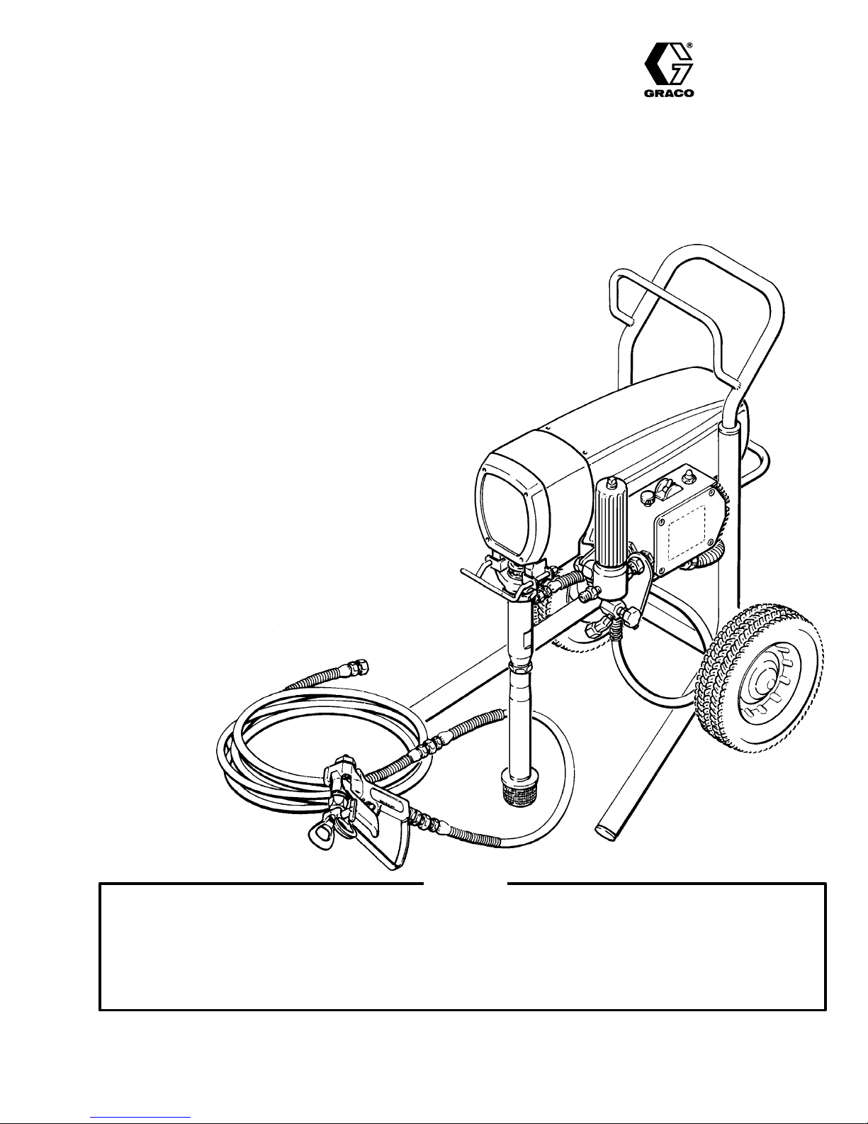
ULTRA 750
3000
psi (210 bar) MAXIMUM WORKING PRESSURE
AIRLESS P
Model 231–033, Series C
Basic
sprayer on Upright cart without
hose or gun
Model 231–042, Series B
Complete
gun, RAC IV, DripLess
and SwitchT
sprayer on Upright cart with hose,
T
ip Guard
ip
Model 221–120, Series C
Basic
sprayer on Lo–Boy cart without
hose or gun
Model 221–130, Series B
Complete
gun, RAC IV, DripLess
and SwitchT
U.S. PATENT NO. 4,323,741, 4,397,610
PA
TENTED 1983, CANADA
AND OTHER PATENTS PENDING
sprayer on Lo–Boy cart with hose,
T
ip Guard
ip
AINT SPRA
YER
Hazard of Using Fluids Containing Halogenated Hydrocarbons
Never
use 1,1, 1–trichloroethane, methylene chloride, other halogenated hydrocarbon solvents or fluids containing
such
solvents in this equipment. Such use could result in a serious chemical reaction, with the possibility of explo
sion,
which could cause death, serious bodily injury and/or substantial property damage.
Consult your fluid suppliers to ensure that the fluids being used are compatible with aluminum and zinc parts.
Refer to the T
echnical Data on page 47 for more information.
GRACO INC. P.O. BOX 1441
WARNING
COPYRIGHT
MINNEAPOLIS, MN
1986, GRACO INC.
MODEL
55440–1441
231–042 SHOWN
-
Page 2

TABLE OF CONTENTS
INTRODUCTION 2.
SAFETY WARNINGS 4.
AVERTISSEMENT 6
ADVERTENCIA 8
SETUP 10
OPERATION 11
SHUTDOWN
FLUSHING
TROUBLESHOOTING
. . . . . . . . . . . . . . . . . . . . . . . . . . . . . . . . . . . . . .
Startup 11
Cleaning
GUIDELINES
When T
How
Motor W
Low
No
Excessive
Motor
Electrical
Spin Test 22.
Bridge Test 23.
o Flush
to Flush
Output
Output
Is Hot And Runs Intermittently
. . . . . . . . . . . . . . . . . . . . . . . . . . . . . .
. . . . . . . . . . . . . . . . . . . . . . . . . .
. . . . . . . . . . . . . . . . . . . . . . . . . . . . .
. . . . . . . . . . . . . . . . . . . . . . . . . . . . . . . .
. . . . . . . . . . . . . . . . . . . . . . . . . . . . . . . . .
. . . . . . . . . . . . . . . . . . . . . . . . . . . . . . . . . . .
a Clogged T
AND CARE
. . . . . . . . . . . . . . . . . . . . . . . . . . . . .
on’t Operate
. . . . . . . . . . . . . . . . . . . . . . . . . . . . . .
. . . . . . . . . . . . . . . . . . . . . . . . . . . . . . .
Pressure Fluctuations
Short
. . . . . . . . . . . . . . . . . . . . . . . . . . . . . . . .
. . . . . . . . . . . . . . . . . . . . . . . . . . . . . .
ip 12.
. . . . . . . . . . . . . . . . . . . .
. . . . . . . . . . . . . . . . . . . . .
. . . . . . . . . . . . . . . . . . . . . . . . . . .
GUIDE
. . . . . . . . . . . . . . . . . . . . . .
. . . . . . . . . . .
. . . . . . . .
. . . . . . . . . . . . . . . . . . . . . . . . . . .
13.
14.
15.
16.
19.
20.
20.
21.
21.
REPAIR
General
Motor
Power
On/Off
Bridge
Circuit
Circuit
Pressure
Pressure
Bearing
Connecting Rod Replacement
Drive
Motor
Displacement
PARTS
Displacement Pump
Upright
Lo-Boy
Pressure
Wiring
ACCESSORIES 46
TECHNICAL
DIMENSIONS 47
GRACO
THE
GRACO W
Repair Information
Brush Replacement
Supply Cord Replacement
Switch Replacement
Rectifier Replacement
Breaker Replacement
Board Replacement
Control Replacement
Control Adjustment
Housing &
Housing Replacement
Replacement
Pump Repair
DRA
WINGS & LISTS
Sprayer
Sprayer
Control
Diagram
. . . . . . . . . . . . . . . . . . . . . . . . . . . . . .
DA
TA 47.
. . . . . . . . . . . . . . . . . . . . . . . . . . . . . . . .
PHONE NUMBERS
ARRANTY AND DISCLAIMERS
. . . . . . . . . . . . . . . . . . . . . . .
. . . . . . . . . . . . . . . . . . . . . .
. . . . . . . . . . . . . . . . . . . . . . . . . .
. . . . . . . . . . . . . . . . . . . . . . . . . .
. . . . . . . . . . . . . . . . . . . . . . . . .
. . . . . . . . . . . . . . . . . . . . . . . . . . .
. . . . . . . . . . . . . . . . . . . . . . . . . . .
. . . . . . . . . . . . . . . .
. . . . . . . . . . . . . . . . .
. . . . . . . . . . .
. . . . . . . . . . . . . . . .
. . . . . . . . . . . . . .
. . . . . . . . . . . . . . .
. . . . . . . . . . . . . . . .
. . . . . . . . . . . . .
. . . . . . . . . . . . . . .
. . . . . . . . . . . . . .
. . . . . . . . . . . . . . .
. . . . . . . . . . . . . . . .
. . . . . . . . . . . . . . . . . .
.
24.
25.
26.
26.
27.
27.
28.
29.
30.
32.
33.
34.
36.
39.
40.
42.
44.
45.
47.
48.
ULTRA 750
Your
new Ultra 750 Sprayer functions
ferently
help
ing
than other airless paint sprayers. This section will
you become familiar with the sprayer before operat
it.
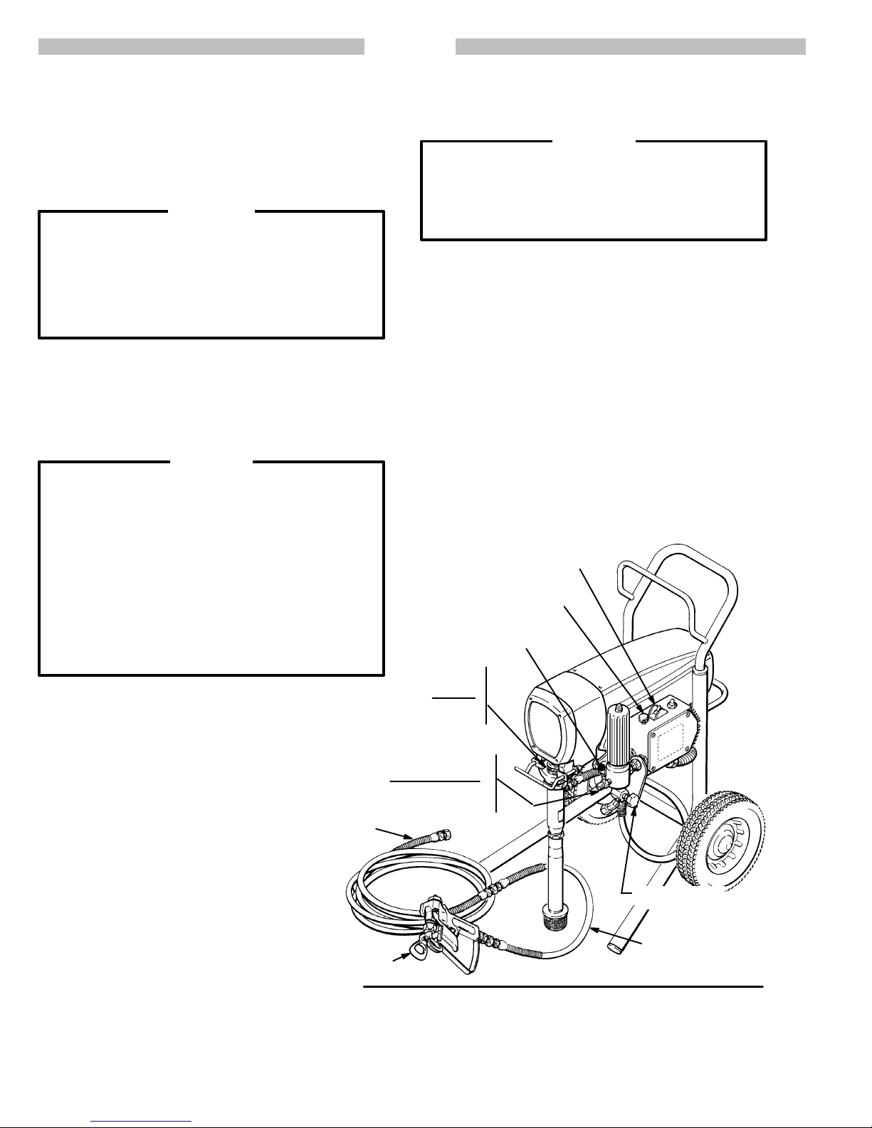
BASIC COMPONENTS
and operates dif
Pressure Control
The
pressure control includes
sprayer
sensing device and a current overload circuit breaker
with
control is to control the motor speed so that the sprayer
maintains constant fluid pressure at the pump outlet.
, the pressure adjusting control knob, a pressure
a manual reset button. The function of the pressure
an ON/OFF switch for the
Motor
The
DC motor has sealed bearings and replaceable
tor brushes. Its function is to drive the displacement
pump
at the
rate needed to supply suf
at
the selected pressure. W
control and motor cause the pump to cycle whenever
is fluid or pressure demand.
there
cling,
the motor sounds like an automobile starter crank
ing. When the pump is not cycling, the motor may hum
intermittently until the fluid pressure stabilizes, then the
motor
will shut itself of
to the sprayer and it will stay pressurized and ready to
use
until you manually shut it of
Because the motor is DC, it is less sensitive to low voltage or voltage fluctuations than an AC motor , and a
heavy gauge extension cord of up to 150 ft. (45 m) can
be
used.
307–786
orking together
f. However
ficient paint volume
, the pressure
When the pump is cy
, there will still be power
f and relieve pressure.
INTRODUCTION
Drive Assembly
The
sealed drive assembly
motor
to the displacement pump.
Displacement Pump
The
positive displacement, volume–balanced pump pro
vides
equal fluid delivery on both the up
strokes.
Graco Throat Seal Liquid, helps prevent damage to the
throat
packings and piston rod.
Fluid Filter
The
fluid filter strains the paint to help avoid clogs in
hose
and spray tip. The filter includes a reusable element
and
has a pressure drain valve for manually relieving fluid
pressure.
Hoses
The
grounded, nylon spray hoses have spring guards on
both
ends. The 50 ft. (15.2 m) hose has a 1/4 in. ID. The
3 ft.
(0.9 m), 3/16
movement. The nylon hose material acts
dampener to absorb pressure fluctuations.
Spray Gun & RAC IV DripLess Tip Guard
Graco high pressure spray guns have a trigger safety
prevents accidental
which
See the Detail in Fig 3–1.
sprayer
verse–A–Clean IV SwitchT
remove
the
a
tion
also has a
clogs from the spray tip without removing it from
gun. The Reverse–A–Clean IV DripLess tip guard is
safety feature which helps reduce the risk of fluid
injury
mo
-
-
-
-
-
The pump has a
in. ID hose provides more flexible gun
filter for final paint straining. The Re
.
transfers power from the DC
and down pump
wet–cup which, when filled with
the
as a pulsation
triggering when it is engaged.
The gun provided with the
ip uses high pressure fluid to
injec
-
-
-
Page 3
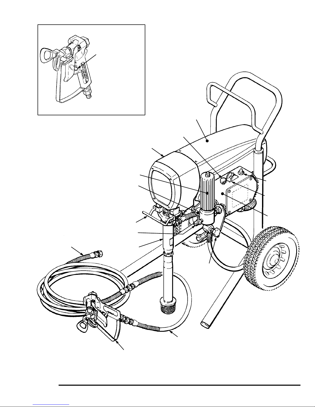
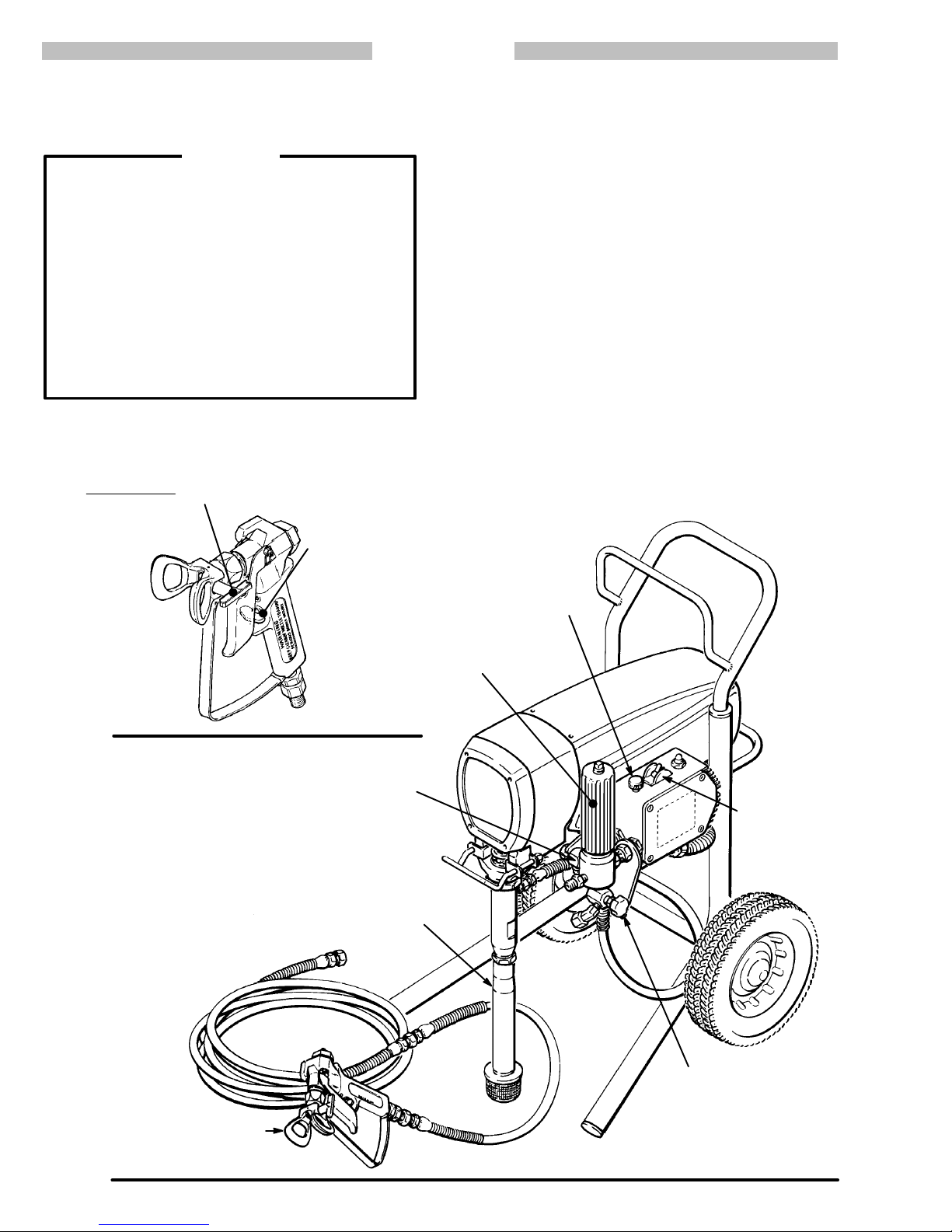
TRIGGER SAFETY
SHOWN ENGAGED
PRESSURE
ADJUSTING KNOB
MOTOR
50 FT (15 M)
MAIN HOSE
SECONDAR
ON UPRIGHT CAR
Y HOSE OUTLET
PAIL HANGER
FLUID OUTLET
DISPLACEMENT
DRIVE ASSEMBL
FLUID FIL
TER
TS ONL
PUMP
Y
Y
PRESSURE
DRAIN
V
RESET BUTT
ON/OFF SWITCH
PRESSURE
CONTROL
ALVE
ON
Fig 3–1
3 ft. (0.9 m) HOSE
CONTRACTOR GUN
WITH RAC IV DRIPLESS TIP GUARD AND
517 SIZE SWITCHTIP
307–786
3
Page 4
SAFETY
HIGH
PRESSURE SPRA
FOR PROFESSIONAL USE ONLY. OBSER
W
ARNINGS
Y CAN CAUSE SERIOUS INJUR
VE ALL W
ARNINGS
Y.
Read and understand all instruction manuals before operating equipment.
FLUID
INJECTION HAZARD
General Safety
This equipmen
gun, leaks or ruptured components can inject fluid through your
skin
and into your body and c
including
the e
into
NEVER
NEVER
back”
p
ALWAYS
ing.
ALWAYS follow the Pressure Relief Procedure, below, before
cleaning
ment.
NEVER
Be sure equipment safety devices are operating properly before
each
u
t g
enerate
the need for a
yes o
r o
p
oin
t the s
put hand o
aint
; t
his is NO
have the tip g
o
r r
emovin
t
ry to sto
se.
s very high f
mputation
n t
he skin can cause serious damage.
pra
y gun at a
r f
inger
s over the s
T a
n a
uar
d i
n p
g the s
pra
p o
r d
eflec
t l
lui
d p
ressure
aus
e e
xtremely seriou
. A
lso
, f
lui
nyon
e o
r a
pra
e o
n the s
r s
ervicin
y tip. N
ir spray system.
lac
y tip o
eaks with you
d i
njecte
t any part o
EVER tr
pra
y gun when s
g any s
r hand o
. S
pra
s b
d o
yste
y from t
odil
r s
f the b
r b
ody.
y i
njury,
plashed
y t
o “
pray-
m e
he
ody.
blow
quip-
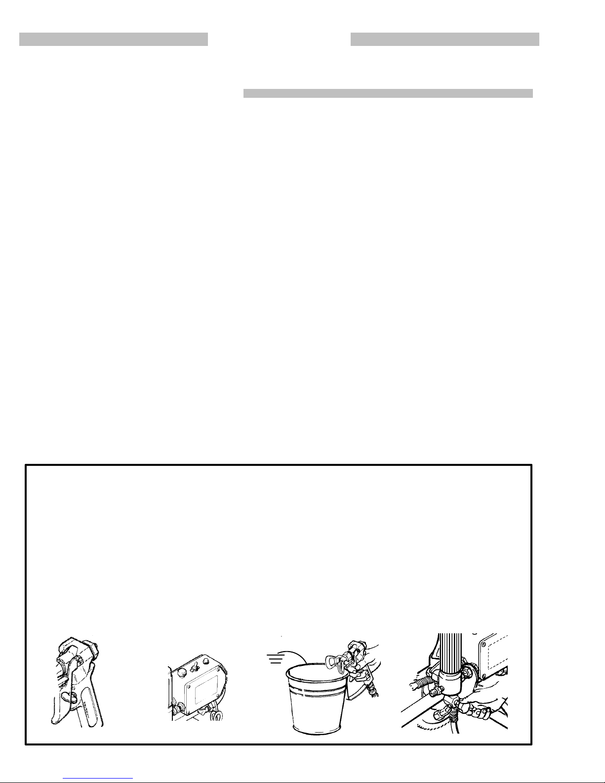
Medical Alert––Airless Spray Wounds
If any fluid appears to penetrate your skin, get EMERGENCY
MEDICAL CARE AT ONCE. DO NOT TREAT AS A SIMPLE
CUT.
Tell the d
Note
t
o P
hysician
octo
r e
xactly wha
:
I
njectio
n i
n t
t f
h
lui
e s
d w
as injected.
ki
n i
s a t
raumati
c i
njury
. I
t i
important to treat the injury surgically as soon as possible. Do
not dela
with som
Consultation
geon may b
y t
reatmen
e e
xoti
w
e a
t t
c c
oating
it
h a p
dvisable
o r
esearch toxicity. Toxicit
s i
njecte
d d
urgeo
n o
irectl
r r
econstructiv
lasti
c s
.
y i
y i
s a c
nt
o t
h
e b
loo
e h
d s
an
oncern
tream.
d s
ur-
Spray Gun Safety Devices
Be sur
use.
m
a
e all gun s
D
o not r
alfunctio
afet
emov
n and r
y d
evice
e o
esul
s are o
r m
odif
y any part o
t i
n serious bodily injury.
peratin
g p
roperl
f the gun; this can c
y b
efore each
ause
Safety Latch
Whenever yo
gun
s
afet
operative.
gering
y l
atc
F
ailur
of the g
u stop s
h in the c
e t
o set the s
un.
praying
lose
, even for a m
d o
r “
safe
y l
atc
” p
h can r
afet
oment
osition
esul
, m
t i
Diffuser
The gun diffuse
tion
when the tip i
Follow the Pressure Relief Procedure, below, then remove the
spray tip
pail.
U
sin
emitted
immediately.
r b
reak
s u
p s
s not i
nstalled
. Aim the gun into a m
g the l
owes
t p
iffuse
ossibl
d into a
i
s n
ot
d
pra
eta
e p
n i
rregula
y and r
. C
hec
l p
ressure
educe
k d
iffuse
ail
, h
oldin
, t
rigge
r s
tream, replac
s the risk o
r o
peratio
g the gun f
r the gun. I
Tip Guard
ALWAYS hav
ing.
The tip g
reduce,
fingers
e the tip g
uar
r a
ny par
d a
t o
but does not p
o
uar
d i
lert
s you to the f
revent
f you
r b
n p
lac
e o
lui
, the risk o
ody clos
n the s
d i
njectio
f a
ccidentall
e to t
he spray tip.
pray gu
n h
Trigger Guard
s
Always hav
t
o r
educ
or
b
e the risk o
umped.
e the t
rigge
f a
r g
uar
d i
ccidentall
n p
y t
riggerin
lac
e o
n the gun when s
g the gun i
Spray Tip Safety
Use extrem
spray
diately
remove
NEVER
relieved
tip c
log
. A
LWAY
t
he spray ti
wipe off b
and the g
e c
autio
s w
S f
n when c
hil
e s
praying
ollo
w the P
p t
o clea
uild–u
p a
un safety latc
leanin
, e
ressur
n i
roun
g o
ngag
e R
t.
d the s
h i
s engaged.
r c
hangin
e the gun s
elie
f P
rocedure an
pra
y tip u
g s
afet
nti
, a
lway
akin
g the gun i
n a
ccidenta
e the d
n w
azar
y p
f i
pra
y l
l p
ressur
s set t
f f
lui
d i
n r
egularly.
irml
y t
f the f
hil
e s
d and h
lacin
g y
praying
t i
s d
ropped
y t
ips
. If t
atc
h i
d t
e is f
he
n-
l t
rig-
njec-
o t
he
luid
iffuser
pray-
elps
our
he
mme-
hen
ully
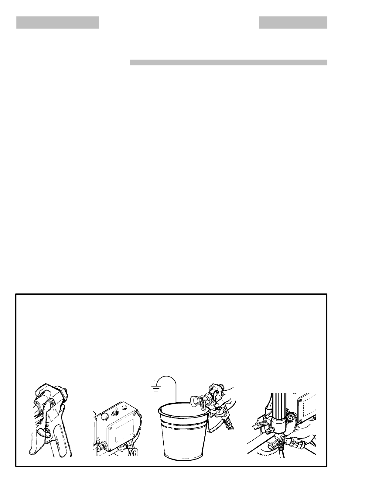
Pressure Relief Procedure
To
reduce the risk of serious bodily injury
jection,
splashing fluid or solvent in the eyes or on the skin,
or injury from moving parts or electric shock, always
this procedure whenever you shut of f the sprayer , when
checking
stalling,
stop
1.
2.
3.
or servicing any part of the spray system, when in
cleaning or changing
spraying.
Engage the gun safety latch.
Turn the ON/OFF switch to OFF.
Unplug the power supply cord.
spray tips, and whenever you
1
307–786
4
, including fluid in
2
follow
4
4.
Disengage
-
-
gun
ger
5.
Engage the gun safety latch.
6. Open the pressure drain valve, having a container
ready
you
the gun safety latch. Hold a metal part of the
firmly to the side of a
the gun to relieve pressure.
to catch the drainage. Leave the valve open until
are ready to spray again.
grounded metal pail, and trig
If you suspect that the spray tip or hose is completely
clogged,
lowing
taining
the part to relieve pressure gradually , then loosen completely.
or that pressure
the steps
nut or hose end coupling and VER
Now clear the tip or hose.
above,
has not been fully relieved after fol
wrap a rag around the tip guard re
Y SLOWL
-
-
-
Y loosen
6
Page 5

MOVING P
Moving
parts
parts.
KEEP CLEAR of moving parts when starting or
the
sprayer
before checking
it
from starting accidentally
ARTS HAZARD
can pinch or amputate your fingers or other body
. Follow the
Pressure Relief Procedure
or servicing any part of the sprayer
.
operating
on page
, to prevent
EQUIPMENT MISUSE HAZARD
General Safety
Any misuse of the spray equipment or accessories, such as
overpressurizing, modifying parts, using incompatible chemicals and fluids, or using worn or damaged parts, can cause
them
to rupture and result in fluid injection, splashing in the eyes
or
on the skin, or other serious bodily injury
property
NEVER alter or modify any part of this equipment; doing so
could
CHECK all spray equipment regularly and repair or replace
worn
Always
tor
damage.
cause it to malfunction.
or damaged parts immediately
wear protective eyewear
as recommended by the fluid and solvent manufacturer
, gloves, clothing and respira
System Pressure
This sprayer can develop
WORKING
accessories
exceed the maximum working pressure of any component or
accessory
PRESSURE
used are rated to withstand this pressure. DO NOT
used in the system.
3000 psi (210 bar) MAXIMUM
.
Be sure that all
Fluid and Solvent Compatibility
BE
SURE that all
with the wetted parts shown in the
patible
on page 47. Always read the fluid and solvent manufacturer’s
literature
before using them in this sprayer
fluids and solvents used are chemically com
, or fire, explosion or
.
.
spray equipment and
TECHNICAL DATA
.
HOSE SAFETY
High
pressure fluid in the hoses can
hose develops a leak, split or rupture due to any kind of wear,
4
damage
cause a fluid injection injury or other serious bodily injury or
property
ALL FLUID HOSES MUST HA VE SPRING GUARDS ON
BOTH ENDS! The spring guards help protect the hose from
kinks or bends at or close to the coupling which can result in
hose
TIGHTEN
pressure
sure
NEVER
tire
movement of the hose couplings. If
ist, replace the hose immediately
pressure hose or mend it with tape or any other device. A repaired
HANDLE AND ROUTE HOSES CAREFULLY. Do not pull on
hoses to move equipment. Keep hoses clear of moving parts
and
or solvents which are not compatible with the inner tube and
cover
above
or misuse, the high pressure spray emitted from it
damage.
rupture.
all fluid connections securely before each use. High
fluid can dislodge a loose coupling or allow high pres
spray to be emitted from the coupling.
use a damaged hose. Before each use, check the en
hose for cuts,
hose cannot contain the high pressure fluid.
hot surfaces of the pump and gas engine. Do not use
of the hose. DO NOT
180 F (82C) or below –40 F (–40
leaks, abrasion, bulging cover
expose Graco hose to temperatures
Hose Grounding Continuity
Proper
hose grounding continuity is essential to maintaining a
grounded
fluid
tag on it which specifies the maximum electrical resistance,
contact
sistance
-
for your hose to check the resistance. If the resistance exceeds
the recommended limits, replace it immediately . An ungrounded
ardous.
spray system. Check the electrical resistance of your
hoses at least once a week. If your hose does not have a
the hose supplier or manufacturer for the maximum re
limits. Use a resistance meter in the appropriate range
or poorly grounded hose can make
Also read
FIRE OR EXPLOSION HAZARD.
be very dangerous. If the
can
, or damage or
any of these conditions ex
. DO NOT try to recouple high
fluids
C).
your system haz
-
-
-
-
-
FIRE OR EXPLOSION HAZARD
Static
electricity is created by the flow of fluid through the pump
and hose. If every part of the spray equipment is not properly
grounded, sparking may occur, and the system may become
hazardous. Sparking may also occur when plugging in or unplugging a power supply cord or using a gasoline engine.
Sparks can ignite fumes from solvents and the fluid being
sprayed, dust particles and other flammable substances,
whether you are spraying indoors or outdoors, and can cause
a fire or explosion and serious bodily injury and property
damage.
If you experience any static sparking or even a slight shock
while
using this equipment, STOP SPRA
Check the entire system for proper grounding. Do not use the
system again until the problem has been identified and
corrected.
Grounding
To
reduce the risk of static sparking, ground the sprayer and
other spray equipment used or located in the spray area.
CHECK
tions
all
1.
your local electrical code for
for your area and type of equipment. BE SURE to ground
of this spray equipment:
Sprayer:
true
connect a ground wire and clamp
earth ground.
YING IMMEDIA
detailed grounding instruc
(supplied) to a
TELY.
all
2.
Fluid
hoses:
500 ft (150 m) combined hose length to
continuity.
Spray
3.
erly
grounded fluid hose and sprayer
Object being sprayed:
4.
5.
Fluid supply container:
6.
All solvent pails used when flushing,
code. Use only metal pails, which are conductive. Do not
place
or
cardboard, which interrupts the grounding continuity
To
maintain grounding
7.
pressure
side
of a grounded metal pail, then trigger the gun.
use only grounded hoses with
See
Hose Grounding Continuity.
gun:
obtain grounding through connection
according to local code.
according to local code.
the pail on a non–conductive surface,
,
always hold a metal part of the gun firmly to the
continuity when flushing or relieving
ensure
.
according to local
Flushing Safety
Reduce the risk of fluid injection injury , static sparking, or
splashing
of
this manual. Follow the
4, and remove the spray tip before flushing. Hold a metal part
of
the gun firmly to the side of
lowest
by following the flushing procedure given on page 14
Pressure Relief Procedure
a grounded metal pail and use the
possible fluid pressure during flushing.
a maximum of
grounding
to a prop
such as paper
.
on page
-
United
States Government safety standards have been adopted under the Occupational Safety and
particularly
the General Standards, Part 1910, and the Construction Standards, Part 1926 – should be consulted.
IMPORTANT
Health Act. These standards –
307–786
5
Page 6
AVERTISSEMENT
La
pulvérisation à haute pression peut causer des blessures très graves.
Réservé exclusivement à l’usage professionnel. Observer toutes les consignes de sécurité.
Bien lire et bien comprendre tous les manuels d’instructions avant d’utiliser le matériel.
RISQUES D’INJECTION
Consignes generales d
Cet appareil produit un fluide à très haute pres sion. Le fluide
pulvérisé
ou
et
Même
dans
NE JAMAIS pointer le pistolet vers quelqu’un ou vers une partie
quelconque
l’ajutage
ture. Ce
TOUJOURS garde
tolet
TOUJOURS
sion
pulvérisateur, ou d’effectuer un
d
NE JAMAI
ou
Avant
rité
par l
e p
d
e r
upture
e
ntraine
sans être sous p
l
es yeux peu
p
endan
d
onné
e l
’appareil.
l
e corps.
c
haqu
f
onctionnent correctement.
s peut p
r des b
d
u c
d
u p
ulvérisateur
t a
ppareil N’es
t l
a p
o
bserve
e plus l
S e
ssaye
e u
tilisation, bie
istole
lessure
t a
orps
r l
ulvérisation.
oin
r d
Soins medicaux
En cas de pénétration de fluide sous la peau: DEMANDER IMMEDIATEMENT
SOIGNER CETTE BLESSURE COMME UNE SIMPLE
COUPURE.
Avis
a
u m
traumatisme. Il est important de traiter chirurgicalement
cette blessure immédiatement. Ne pas retarder le traitement pour effectuer des recherches sur la toxicité. Certains
revêtements ex otiques sont dangereus ement tox iques
quand ils sont injec tés direc tement dans le sang. Il est
souhaitable de consulter un chirurgien es thétique ou un
chirurgien spécialis
Dispositifs d
Avant chaqu
sécurité
d
modifier une partie quelconque du pistolet; ceci risquerait d’entraîner un m
DES S
edecin
: L
a p
e s
écurité du pistolet
e u
tilisation
u p
istole
t f
auvais fonctionnemen
e s
t ou l
e f
luid
énétre
r sous l
s très g
ression
uss
i e
ntraine
. N
E J
AMAIS mettr
. N
E J
t PAS u
a p
rotectio
r la Marc
, a
van
t d
’arrête
r ou d
n s
OIN
S M
énétratio
é d
ans l
, bien s
onctionnen
écurité
e sous p
ressio
n p
a peau ou à l’interieu
raves
, voir même une a
, l
e f
luide éclaboussan
r d
es blessures graves.
AMAI
n compresseu
h à S
e n
t
’assure
n d
’assur
t c
e l
S e
ssaye
n d
e l
’ajutag
uivr
e pour D
ettoye
r o
ravail quelconque sur un
e d
évie
r que les d
EDICAU
es fluides sous l
a r
econstructio
e que tous les d
orrectement
t et d
rovenan
a main o
r de “
refouler
r p
neumatique.
e en p
étendr
u d
’enleve
r les f
uite
ispositif
X D
’URGENCE. NE PAS
n d
. N
e pas e
es blessures graves.
t d
e f
r d
u c
mputation.
t ou e
ntrant
u les d
oigt
” l
a p
lac
e sur l
e p
e l
a P
r l
’ajutag
e p
s avec l
a m
s d
e s
a peau est u
es mains.
ispositifs de
nleve
uites
orps
s s
ein-
is-
res-
e d
artie
ain
écu-
r n
Verrou
d
e s
A chaqu
court
i
p
ositio
la
de fonctionner. Si le verrou de sécurité n’est pas mis, le pistolet
peut s
e f
nstant
n “
e d
éclenche
écurité
ois qu
, t
oujour
fermée
e l’on s
’arrêt
s m
ettr
” ou “
sécurité
r a
ccidentellement
e l
e d
e v
e p
” (
erro
“safe”
ulvérisér
u d
e s
) pour e
. Voir l
, même s’il s
écurit
é d
u p
mpêche
a Fig. 1
, ci–dessus.
’agi
istole
r l
e p
t d
’un
t s
istolet
ur
Diffuser
u
Le diffuseu
d’injection
le
f
onctionnemen
tion,
Détendre
pulvérisateur.
tenant
plus
projete
immédiatement
ur
Protection
TOUJOURS mainteni
tolet du pulvérisateur pendant la pulvérisation. La protection de
l’ajutage
réduire, mais n’évite pas le risque, que les doigts ou une partie
quelconque du corps ne passent ac cidentellement à prox imité
immédiate de l
Consignes d
pulvérisateur
n
Faire ex tremement attention à l’oc casion du nettoy age ou du
remplacement des ajutages du pulvérisateur. Si l’ajutage se
bouche pendan
de sécurité du pistolet. TOUJOURS bien observer la Marche à
Suivre pour Détendre la Pression puis enlev er l’ajutage du
pulvérisateur
NE
pulvérisateur
et
que l
i
r d
a
ccidentell
d
étendr
e l
l
a P
f
ermement contr
f
aibl
e p
ossible
n’est pas
d
a
ttir
e l
J
AMAI
S e
e verro
u p
istole
t sert à d
e q
t d
u d
a p
ression donné
P
e l
pour l
ssuye
a
van
u d
iffuseu
ressio
ointe
r l
e p
, a
ppuye
diffusé sous forme de jet irrégulier, remplacer
l
e d
iffuseur.
’ajutage
r l
’attention su
’ajutag
e du p
e s
écurit
t l
a p
ulvérisation
e n
ettoyer.
r c
e qui s
t que l
e sécurit
iviser le jet e
uan
d l
’ajutag
r r
égulièrement
n en o
bservan
e plus loin puis e
istole
t d
e l
a p
ans un seau e
e s
eau
. P
r sur l
a g
rotectio
n d
r l
es risques d’injection et contribu
ulvérisateur.
é c
oncernant l’ajutage du
, m
ettr
’es
t a
ressio
é du p
ccumul
n n
istole
a p
t à r
e n
t la March
uis
, e
achett
e l
’ajutag
e i
e soit c
t n
éduir
’es
t pas e
. Pour c
nleve
n m
n u
tilisan
e d
u p
e en p
mmédiatemen
é a
utou
ompletement tombée
e soi
t e
e les r
n p
e à S
r l
étal
t l
a p
istolet
lac
r d
e l
ngagé.
lace
ett
uivr
’ajutag
, e
. S
e sur le p
’ajutag
isques
. V
e v
érifica-
e p
n l
e m
ressio
i l
e f
t l
e v
érifier
our
e d
ainn l
luide
is-
e à
errou
e d
u
a
u
Marche
Pour réduire les risques de blessures graves, y compris les
blessures par injection de fluide ou celles causées par des
éclaboussures dans les yeux ou sur la peau, des pièces en
mouvement
marche
à
l’occasion de la vérification, du reglage ou du nettoyage du
systeme
1.
2. Basculer
3.
à Suivre pour Détendre la Pression
ou par électrocution, toujours bien observer cette
à suivre à chaque fois que l’on arrête le pulvérisateur
ou lors du changement des ajutages.
Engager le verrou de sécurité du pistolet.
l’interrupteur de commande de pression sur AR
RET (OFF).
Debrancher le cordón d’alimentation.
12
307–786
6
4. Désengager le verrou de sécurité du pistolet. T out en
maintenant une partie métallique du pistolet fermement
appuyée contre le côté d’un seau en métal, actionner le
pour libérer la pression.
pistolet
,
5.
Engager le verrou de sécurité du pistolet.
6. Ouvrir
Si
ment bouche, ou que la pression n’a pas été complètement
-
libérée
serrer très LENTEMENT un raccord du bout du tuyau ou
l’écrou de retenue de la protection de l’ajutage et libérer
progressivement
4
la soupape de sécurité et la laisser ouverte jusqu’a
ce
que l’on soit pret à se servir de nouveau du pulvérisa
teur
. Débrancher le fil de la bougie.
l’on soupçonne que le tuyau ou l’ajutage du est complète
après avoir procede aux operations ci–dessus, des-
la pression.
6
-
-
Page 7

RISQUES EN CAS DE MAUVAISE UTILISATION DU MATERIEL
Consignes générales d
Toute utilisatio
cessoires
les m
sive,
et de matières incompatibles et l’utilisation de pièces usées ou
abîmées
pièces
sérieuses,
NE JAMAIS alterer ou modifier une piece de cet appareil; ceci
risquerait
Vérifier régulièremen
ments et réparer ou remplacer immédiatement les pièces usées
ou
a
bîmées.
n a
normal
c
omme
, par e
odification
p
eut causer des dégâts à l’appareil o
e
t e
ntraîne
r une i
u
n i
ncendie
d
’entraîner so
e s
écurité
e d
e l
’apparei
xemple
s d
, une e
t tout l
, la mise sous une p
e p
ièces
, l
’utilisatio
njectio
n d
e l
xplosió
n m
auvais fonctionnement.
’apparei
l d
MESURES DE SÉCURITÉ CONCERNANT LES TUYAUX FLEXIBLES
Le fluid
e à haut
dangereux.
rupture
à l
tion, les projections de fluide haute pression qui en proviennent
peuvent entraîner des blessures graves par pénétration sous la
peau
ou p
LES T
TOUS
SORTS
p
rotectio
de
ou
d
e n
tuyau
à l
SERRER
tion.
L
e f
p
roduir
ou
NE JAMAIS utiliser un tuyau endommagé. NE PAS essayer de
refaire le r
avec
d
u r
peut p
ne
e p
ressio
E
n cas d
a s
uit
e d
e l
ar contact
UYAUX FLEXIBLE
S
PIRAL
E D
n c
ontribuen
œud
s sur les t
’endroi
t d
u r
F
ERMEMEN
luid
e sous p
e u
n jet à h
accor
d d’un t
uba
n a
dhesi
as résiste
n c
irculan
e f
uit
e sur l
’usure
, d
e d
, a
ins
i que d
E P
ROTECTIO
t à e
vite
uyau
accor
ressio
aut
f o
r a
uya
u f
r la f
x qui p
d o
u à s
T tous les r
n peut f
e p
ression s’échappan
u h
aut
u par tout a
luide sous pression.
t dans les t
e t
uyau
égât
es dégâts matériels.
S D
ormatio
ourraien
on voisinagé.
accord
air
e p
RISQUES D’INCENDIE OU D’EXPLOSIÓN
De l’électricité statique est produite par le passage du fluide à
grande vitesse dans la pompe et dans les tuyaux. Si toutes les
pieeces de l’appareil de pulvérisation ne sont pas convenablement reliées à la masse ou à la terre, des étincelles peuvent se
produire et l’appareil ris que d’être dangereux. Des étinc elles
peuvent également se produire à l’occasion du branchement ou
du débranchement du cordón d’alimentation. Les étincelles sont
suffisantes pour allumer les vapeurs de solvants et le fluide
pulvérisé, les fines partic ules de pous sieère ainsi que d’autrès
substances inflammables, quand on pulvérisé à l’intérieur ou à
l’extérieur,
ainsi
brancher le pulvérisateur dans une prise se trouvant à a
6
m (20 p
Ne pas brancher ou débrancher un cordón d’alimenations quel
qui’il soit dans la zone où se fait la pulvérisation quand il y à le
moindre
nent
S’il se
sentez la moindre décharge, ARRÊTEZ IMMÉDIATEMENT LA
PULVÉRISATION.
erre.
identifié
Mise
Pour réduire les ris ques de production d’étinc elles d’élec tricité
statique, le pulvérisateur et tous les équipements utilisés ou se
trouvant
ou
la terre dans la region et le type particulier d’équipement, CONSULTER
SURER
bien relié
.
1
e
t e
lle
s p
euven
t c
ause
que des b
f
eu.
p
N
e vous s
à l
à la m
Pulvérisateur:
longe
état, dans une prise de courant convenablement mise à la
terre. Ne pas utilis er d’adaptateur . T outes les rallonges
doivent
lessure
ieds
) d
e l
’apparei
r
isqu
e que des v
rodui
t des é
V
erve
e
t corrigé.
z pas d
a terre ou à l
dans l
a zone de p
asse
. Pour c
l
e code o
que tous les é
s à l
a t
qui d
a
u les r
erre:
Branc her le cordón d’alimentation ou la ral -
oiven
voi
r 3 f
s g
apeur
tincelles d’électricit
érifie
z que le s
a m
onnaîtr
églementation
quipement
t être é
ils e
t être p
rave
s e
l e
t d
e l
’endroi
s e
u s
ystèm
asse
ulvérisatio
e l
e d
quipés d’un
revues pou
r u
t des d
ncor
ystèm
etai
s d
l d
e p
ulvérisatio
n d
iquid
e o
n ou d
’autrès dégâts.
e p
ulvérisatio
, de f
s o
u d
’un
OIVEN
N AUX B
n d
t e
s a
e s
aute
r un r
ressio
n n
utr
e m
oyen
n i
ncendi
égât
t o
ù se fait l
e p
résente
é s
tatique
e e
ntie
e a
van
t que l
n d
oiven
l des i
nstruction
s é
lectrique
e p
ulvérisatio
e p
ris
r 1
n o
ressio
e p
roduit
s c
u d
es ruptures de
u d
’autrè
s b
n e
t ses e
uyau
x peut être t
issure
, d
échirur
e m
auvais
T A
VOI
R DES R
OUTS! Le
e p
liures
ntraîne
van
i d
e o
s m
t être r
, d
r l
a r
t c
haqu
accor
d d
t par l
e r
e r
épare
. U
n t
uya
u une e
atériels
a p
ulvérisation.
s dans l
, o
u s
i vou
r est bien mis à l
e p
roblèm
eliés
s d
s l
ocales
n s
uivant
e à 3 f
iche
5 a
mpères.
u des a
n e
xces-
himiques
lessures
quipe-
e o
e u
tilisa-
ES-
s s
pirales
e b
oucles
uptur
e d
e u
tilisa–
esserre
accord.
r l
e t
uyau
u r
éparé
xplosión,
. T
oujours
u m
oins
’ai
r p
ren-
s r
e s
à l
a t
erre
e mise à
. S
’AS-
s s
s e
n b
c-
rès
es-
at-
oit
ont
on
Pression
Ce pulvérisateur peut produire une PRESSION MAXIMUM DE
TRAVA IL
du
pression max imum de trav ail de ce pulv érisateur. NE P AS
depasser la pression maximum de travail d’aucun des éléments
ou
Compatibilité chimique de
BIEN S’ASSURER que tous les corps des solvants utilisés sont
chimiquement compatibles avec les parties mouillées indiquées
dans les Technical Data
les
lisés
MANIPULE
SOIGNEUSEMENT
u
tirant
sont
tuyau.
à
Continuité d
Une bonn
tiell
tion.
u
air, au m
d’étiquette
contact
límites
la
celle–ci dépasse les límites recommandées, remplacez le tuyau
immédiatement.
à
Lisez
dessus.
2
3
4.
5
6.
7
Mesures d
Pour réduir
et
boussures,
la page 14 de ce manuel. Observer la “Marche à Suivre pour
Détendre
pulvérisateur
pistolet
utiliser
210 bar (
p
ulvérisateu
a
ccessoires utilisés avec ce
d
ocument
a
van
t d
sur l
e t
pas c
ompatible
N
E PAS e
8
2 C (180 F) ou i
e c
e pour m
V
érifie
oin
qui p
avec le f
d
e r
g
l
a t
.
.
.
ésistanc
amm
e a
err
e i
ncorrect
a
ussi LE
Tuyaux flexibles:
terre,
n
et
a
yan
pieds).
circuit
Pistolet
flexible
terre.
Récipient d’alimentation:
tions
l
ocales.
Objets, matériel ou surfaces reçevant la pulvérisation:
server
Tous le
le code ou les réglementations loc ales. N’utilis er que des
saux
m
le
seau sur une s
d
u c
ou
la terre.
.
Pour conserver la continuité de la mise à la terre quand on
l
e m
rince
tenir une partie métallique du pistolet fermement appuy ée
contre
du
p
istolet.
les r
isque
l
a P
f
ermement appuyé
l
a p
ressio
300
0 l
b/po2)
r e
t ses a
. S
ccessoire
t a
s c
s e
t b
e s’en servi
R LES T
uyau
e l
ontinuit
ainteni
z l
a r
ésistanc
s une fois par s
récis
ournisseu
pproprié
U
S R
’utilise
t une l
S
e r
eporte
d
e mise à l
: Réalise
e
t à u
l
e cod
s s
eau
étalliques conducteurs d
arto
n car cela i
atérie
l
e côté d’un seau e
e s
écurit
e les r
s dûs aux e
o
bserve
ression
a
van
, a page 47. T
rochure
s d
u f
abrican
r d
ans c
UYAUX AVEC PRECAUTION E
LEUR C
. N
e pas u
s avec l
xpose
a mise à l
é de l
r l
a mise à l
e l
e m
e pour v
n t
uya
e peut e
ISQUE
r que des t
ongueu
r l
n p
ulvérisateur dèj
e o
u l
x de s
l o
isque
r l
” d
t l
e r
n l
a p
HEMIN
tilise
r d
’envelopp
r l
e t
uya
u à des t
nférieure
a terre des tuyaux
a mise à l
a t
e é
lectriqu
emaine
a r
ésistanc
r d
e t
aximum
Afin d’assurer la continuité de la mise à la
r é
a mise à l
urfac
u q
a m
lus faibl
uyau
. U
otr
e t
u sans mise à l
ntraîne
r des r
S D
’INCENDI
uyau
r m
aximu
galemen
a t
err
e des t
a t
o
bserve
es réglementations locales.
olvants
u
e non c
nterromprai
uan
d o
n l
n m
é c
oncernant l
s d
e b
lessures pa
tincelle
s d
arch
e à s
onné
e à l
incage
. M
e c
ontr
e p
’assure
r que tous les é
s sont c
onçu
s pour r
ppareil.
orps
oujour
s lire s
t des f
e p
ulvérisateur.
. N
e f
s à –
a t
err
e d
e d
. S
i v
e é
x o
tilise
uya
x c
omportan
m c
t a
u p
err
á c
tilisé
onductric
ibér
éta
’electricit
uivr
a page 6 en
ainteni
e l
e côté d’un seau e
ossibl
luide
e pas d
luide
e i
err
e vo
otr
lectrique maximum
z u
u e
isque
uyaux.
e e
r l
s pour l
e l
e l
l puis a
e pour l
éplace
s o
u d
ntérieur
e o
empérature
40 C (–40 F).
e des t
e l
’ensembl
s t
uyau
e t
uya
u n
u l
a f
abrican
n m
ètr
e d
t v
érifie
z l
a t
err
e o
s pour v
E O
U D
’EXPLOSIÓN ci–
t une m
ombiné
e d
aragraphe Continuité du
n l
e r
accordan
onvenablemen
e code o
e r
’électricité. N
e c
omm
t la c
ontinuit
a p
ression
ppuye
e R
incage
r p
énétratio
e s
tatiqu
e r
enleve
r une p
arti
e p
endan
léments
ésiste
oigneusement
s e
t s
olvant
T C
HOISIR
r l
e f
e s
uyau
u avec une m
u les r
inçage
incag
t l
luid
olvant
s qui n
u e
xtérieur
s s
upérieures
x est e
e d
e v
aporisa-
x à f
luides e
e c
omport
, p
t pour a
voi
e r
ésistance de
a r
ésistance
otr
e s
ysteme.
ise
à l
e 150 m (
t à u
n t
t r
elié
églementa-
: o
bserver
e p
as mettre
e sur d
u p
é d
e l
a mise à
, t
oujour
s m
r sur l
a d
n d
e l
a p
e ou aux é
e d
onnée
r l
’ajutag
e m
étalliqu
n m
e r
incage.
a t
étente
307–786
r à la
s u
e e
e d
ssen-
e p
renez
r l
. S
ise
erre
1500
uyau
s à l
ob -
apier
ain-
eau
cla-
e d
e d
éta
l e
ti-
n
e
u
t à
as
es
i
a
à
u
u
t
7
Page 8
ADVERTENCIA
EL
ROCIADO a ALTA PRESIÓN PUEDE CAUSAR GRA
SOLO P
Lea y entienda todo el manual de instrucciónes antes de manejar el equipo.
PELIGRO DE INYECCIÓN DE FLUIDO
Seguridad
Este
equipo genera un fluido a una presión muy alta. El rociado
de la pistola, los escapes de fluido o roturas de los componentes
lesiones extremadamente graves, incluyendo a veces la
necesidad de amputación. También, el fluido inyectado o salpicado
NUNCA apuntar la pistola hacia alguien o alguna parte del
cuerpo.
quilla.
un
sistema de rociado de aire.
SIEMPRE tener colocado el protector de la boquilla en la pistolamientras
SIEMPRE seguir el procedimiento de descarga de presión,
dado
vicioa
NUNCA
cuerpo.
Asegurar
funciónando
Tratamiento
Si pareciera que un poco de fluido penetró la piel, conseguir
TRATAMIENTO
TRATAR LA HERIDA COMO UN SIMPLE CORTE. Decir al
médico
A
viso al médico:
causa
mente la lesión a la brevedad posible. No demorar el
tratamiento
suma importancia en algunas pinturas exóticas cuando se inyectan directamente al torrente sanguineo. Sirá conveniente
consultar
de
las manos.
general
pueden inyectar fluido en la piel y el cuerpo y causar
en los ojos puede causar graves daños.
NUNCA colocar la mano o los
NUNCA
másabjo, antes de
cualiquier equipo del sistema.
tratar de “hacer retornar la pintura”; este NO es
se está pulverizando.
tratar de parar o desviar los escapes
que todos los aparatos de seguridad del equipo están
bien antes de cada uso.
médico
médico DE URGENCIA DE INMEDIATO. NO
exactamente cua fluido fue.
una lesión traumática.
Si se llega a inyectar este fluido en la piel se
para investigar la toxicidad. La toxicidad es algo de
a un especialista en cirugia plástica o reconstructiva
ARA USO PROFESIONAL. RESPETE LOS A
dedos encima de la bo–
limpiar o sacar la boquilla o de dar ser
con la mano o el
Es importante tratar
quirúrgica
VES LESIONES.
VISOS DE ADVERTENCIA.
Aparatos
Asegurar
funciónando bien antes de cada uso. No sacar ni modificar
ningúna
miento
Pestillo
Cada
momento, siempre colocar el pestillo de seguridad en la posición “cerrada” lo que deja la pistola inoperante. El no hacerlo
puede
Difusor
El
difusor de la pistola dispersa el chorro pulverizado y reduce
el riesgo de inyección cuando no está instalada la boquilla.
Revisar
procedimiento de descarga de presión, dado más abajo, y
después
co,
sosteniéndola bien firme contra el. Utilizando la presión más
bajo
perso
Protector
SIEMPRE
mientras
contra
la
colocación accidental de los dedos o cualquier otra parte del
cuerpo
Seguridad
Tener
ra a obstruirse mientras está pulverizando,
tillo de la pistola de inmediato. SIEMPRE seguir el pro–
cedimiento
quilla
NUNCA
quilla
y
el pestillo este enganchado.
de seguridad de la pistola pulverizadora
que todos los aparatos protectores de la pistola están
pieza de la pistola pues podria causar el malfuncióna
de
la misma con las consiguientes lesiones personales.
de seguridad
vez que se deje de pulverizar
llevar al disparo imprevisto de la pistola.
con regularidad el
sacar la boquilla. Apuntar la pistola a un balde metáli
posible, disparar la pistola. Si el fluido emitido no sale dis
en un
chorro irregular
funciónamiento del difusor
, reemplazar de inmediato el difusor
, aunque sea por un breve
de la boquilla
tener
el protector de la boquilla colocado en la pistola
se está pulverizando.
el peligro de inyección
cerca de la boquilla.
Este protector llama la atención
y ayuda a reducir
de la boquilla pulverizadora
mucho cuidado al limpiar o cambiar las
de descarga de presión
para limpiarla.
limpiar la acumulación de pintura alrededor de la bo–
antes de que se haya descargado por completo la presión
boquillas. Si llega
enganchar el pes
y después sacar la bo–
-
. Seguir el
-
.
, pero no evita,
-
-
Procedimiento
Para
reducir el riesgo de
cluyendo inyección o lesiones causadas por piezás en
movimiento o choque eléctrico, siempre seguir este
procedimiento
o
dar servicio a cualquier
al
instalar
deja
1.
2. Mover
3. Desenchufar
4.
, limpiar o cambiar las boquillas, y cada vez que se
de pulverizar
Enganchar el pestillo de la pistola.
el interruptor eléctrico (ON/OFF) a la posición OFF
(apagado).
Desenganchar el pestillo de la pistola. Sujetar una parte
metálica
y
disparar la pistola para descargar la presión.
de descarga de presión
sufrir graves lesiones corporales, in
al apagar la máquina pulverizadora, al revisar
el cordón electrico.
de la pistola
parte del sistema de pulverización,
.
bien firme contra un balde de metal,
12
307–786
8
5.
Enganchar el pestillo de la pistola.
-
6. Abrir
Si se sospecha que la boquilla o la manguera está completamente obstruida, o que no se ha descargado por completo
anterior, aflojar MUY LENTAMENTE la tuerca de retención
del
manguera y descargar gradualmente la presión, después,
aflojarlo por completo. Luego, despejar la boquilla o la
manguera.
la válvula de presión y tener listo un reclipiente
recibir la pintura. Dejar la válvula de alivio de presión
abierta hasta que se este nuevamente listo para pulverizar.
la
presión después de haber seguido el procedimiento
protector de la boquilla o acoplamiento
de la punta de la
4
para
6
Page 9

PELIGRO POR MAL USO DEL EQUIPO
Seguridad
Cualquier
como sobre presurización, modificación de piezás, uso de
matériales
piezás dañadas o desgastadas, puede hacen que se rompan
y causen la inyección de fluido u otras lesiones corporales
graves,
NUNCA alterar o modificar ningúna pieza de este equipo; el
hacerlo
REVISAR con regularidad el equipo pulverizador y reparar o
reemplazar
general
mal uso del equipo pulverizador o los accesorios, tal
y productos quimicos incompatibles, o utilización
incendio, explosión o dañon a la propiedad.
podria causar una avería.
de inmediato las piezás dañadas o desgastadas.
de
SEGURIDAD EN EL USO DE LAS MANGUERAS
El fluido que escapa a alta presión por las mangueras puede
ser
muy peligroso. Si en la manguera se desarrolla un
una
rotura o rajadura debido a cualquier tipo de desgaste, daño
o maltrato, el chorro a alta presión emitido por alli puede causar
una lesion por inyección u otras lesiones corporales graves o
daños
a la propiedad.
!TODAS LAS MANGUERAS PARA FLUIDOS TIENEN QUE
TENER
Estas
en los acoplamientos o cerca de ellos, los que podrian
traducirse
Antes
El fluido a alta presión puede desalojar un acoplamiento suelto
o
NUNCA usar una manguera que está dañada. Siempre,
revisarla
abultada, o acoplamientos sueltos o dañados. Si llegara a en
contrarse cualquiera de estás condiciónes, reemplazar de inmediato la manguera. NO intentar racoplar una manguera de
alta presión o enmendarla con cinta adhesiva u otro matérial
similar. Una manguera que ha sido remendada no aguante el
fluido
GUARDAS DE RESORTE EN AMBOS EXTREMOS!
protegen las
en roturas de la manguera.
de usarlas, APRET
dejar que por el escape un chorro a alta presión.
en busca de cortaduras, escapes, abrasion, cubierta
a alta presión.
mangueras contra dobleces o retorceduras
AR bien firmes
todas las conexiones.
escape,
-
Presión
está
presión DE TRABAJO MÁXIMA.
pulverizador
tar la presión máxima de trabajo de está pulverizadora. NO ex
ceder la presión máxima de trabajo de ningún componente o
accesorio
del sistema
pulverizadora puede desarrollar
y sus accesorios
de este sistema.
Asegurar que todo el equipo
tienen la capacidad para aguan
210 barías (3000 psi) de
Compatibilidad de fluido
Siempre leer las instrucciónes del fabricante del fluido y sol-
antes de usarlos en está
vente
na
47.
Siempre usar gafas, guantes, vestimetas protectora y un
respiradero,
del solvente.
MANEJAR Y PASAR CUIDADOSAMENTE LAS MANGUERAS.
usar fluidos o solventes que sean incompatibles con el tubo in
terno
t
emperatura
a
Continuidad
tal como recomiendan los fabricantes del fluido
No tirar de las mangueras para mover el equipo.
y la
cubierta dela manguera. N
s s
obr
e 82 C (
del circuito de puestá a tierra de la
pulverizadora, dadas en la pági
O e
xpone
r las m
angueras
180 F) o bajo –
40 C (–40 F).
y
No
manguera
La continuidad del circuito de puestá a tierra apropiado es
esencial para mantener conectado a tierra el sistema pulverizador. Es indispensable revisar la resistencia eléctrica
máxima
vez
se
el proveedor o fabricante de la manguera para la información
sobre
la
límites
riesgado
a tierra en malas condiciónes. Leer también la información
sobre
de las mangueras de aire y de fluido por lo menos una
a la semana. Si la manguera no tiene una etiqueta
especifica la resistencia eléctrica, ponerse en contacto con
los límites de resistencia. Usar un metro de resistencia en
gama apropiade para comprobar la resistencia; si excede los
recomendados, reemplazarla
tener una manguera sin puestá a tierra o con la puestá
RIESGO DE INCENDIO O EXPLOSION
de inmediato. Es muy ar
en la cual
, más arriba.
-
-
-
-
-
PELIGRO DE INCENDIO O EXPLOSION
El
flujo a alta velocidad del fluido al pasar por la bomba y man
guera
crea electricidad estática. Si todas las partes del
pulverizador no tienen buena tierra, pueden ocurrir chispas,
convirtiendo al sistema en algo peligroso. T ambién, pueden
producirse chispas a enchufar o desenchufar el cordón
electrico
inflamar
verizado, particulas de polvo y otras sustancias in flamables,
sea
o
Enchufar siempre la pulverizadora a un tomacorriente que se
encuentre
que se va a rociar. No enchufar o desenchufar ningún cordón
electrico
ista
Si
choque electrico mientras se usa el equipo, DEJAR DE PULVERIZAR DE INMEDIATO. Revisar todo el sistema en busca
de una tierra apropiada. No usar de nuevo el sistema hasta
haber
Peusta
Para
pulverisadora
se encuentre en el lugar que se va a rociar . CONSULTAR el
codigo
conexiones a tierra exigidas para la zona y tipo de equipo.
ASEGURAR
1.
o al usar un motor
los vapores de los solventes y el chorro de fluido pul
al aire libre o bajo techo, lo que podria causar una explosión
incendio y graves lesiones corporales
a por lo menos 6 m (20
en el lugar
la posibilidad de que queden
ocurre una chispa de electricidad estática o incluso un ligero
identificado y soluciónado el problema.
donde se está rociando cuando todavia ex
de gasolina. estás chispas pueden
pies) de la maquina y del area
vapores inflamables en el aire.
a tierra
reducir el reisgo de chispas estáticas, conectar a tierra la
Pulverizadora:
sor, cada uno un enchuf de très patas en buen estádo, a
un
adaptador. Totos los cables extensores tienen que tener
très
y todo el otro equipo de pulverisar que se use o
electrico de la localidad para las instrucciónes sobre
de conectar a tierra todo
enchufar el cordón electrico, o cable
tomacorreinte con puesat a tierra aporpiado. No usar un
hilos y una capacidad de 15 amperios.
equipo
y daños al a propiedad.
las
este equipo pulverisador:
exten
-
2.
Mangueras para fluidos:
puestá
a
pies),
también al párrafo sobre continuidad a tierra de la
manugeura.
Pistola:
3.
-
-
guera
4.
Suministrar un recipiente:
localidad.
5.
Objeto
local.
6.
Todos
conformidad con el código local. Usar
de
superficie no conductiva, como papel o cartón, que interumpe
7.
Para mantenar la continuidad a tierra durante el lavado o
tierra de una longitud combinada de 150 m (500
para asequrar buena continuidad a tierra. Referirse
hace la puestá a tierra conectándola a una man-
de fluido y pulverizadora bien conectadas a tierra.
que se está rociando:
los baldes de solvente
metal,
que sean conductivos. no colocar el balde en una
la continuidad a tierra.
descarga de presión,
de la pistola bien firme contra el costado del
metal,
después apretar el gatillo.
usar solamente mangueras con
de acuerdo al código de la
de conformidad con el codigo
usados durante el lavado, de
solamente baldes
siempre apoyar una parte metálica
Seguridad durante el lavado
Para
reducir el riesgo
piel, o que ocurra una descarga de electricidad estática,
siempre seguir las INSTRUCCIÓNES PARA EL LAVADO,
dadas
-
en la página 14. Seguir el
de
presión
lavar.
el costado de un
posible
en la págna 8, y quita la
Apoyar una parte metalica de
de fluido durante el lavado.
de que se inyecte o salpique fluido en la
procedimiento de descarga
boquilla rociadora antes
balde de metal
la pistola bien firme contra
y usar le presión más baja
balde de
307–786
de
9
Page 10
SETUP
NOTE: Refer
to Fig 10–1 for Steps 1 to 3.
1. Connect Hose and Gun. Connect the gun, 3 ft.
hose and 50 ft. hose. Remove the disposable cap
from the outlet nipple. Screw the gun and hose assembly
onto the nipple.
NOTE: Don’t use thread sealant, and don’t install the
tip yet!
spray
WARNING
If
you supply your own hoses and spray gun, be sure
the hoses are electrically conductive, that the gun
has
a tip guard, and that each part
3000 psi (210 bar) Working Pressure
duce
the risk of serious
bodily injury caused by static
is rated for at least
. This is to re-
sparking, fluid injection or over–pressurization and
rupture
of the hose or gun.
2. Two Gun Hookup. Remove the plug from the 1/4
npsm(m) secondary hose outlet. Connect a hose
and gun to the outlet. Use a 1/4 in. ID, 50 ft. long
(minimum) main hose. For more flexible gun movement,
install a 3/16 in. ID, 3 ft. hose between the main
hose
and the gun.
CAUTION
To
avoid damaging the pressure control, which
result in poor equipment performance and component
damage, follow these precautions:
may
5.
Plug in the Sprayer . Be sure the ON/OFF switch
is
OFF
. Then plug the cord into a grounded electrical
outlet
at least 20 ft. away from the spray area.
WARNING
Proper electrical grounding is essential to reduce
the
risk of fire
ous
bodily injury and property damage. Refer to the
warning section
on
page 5
6. Flush
was
left in to protect pump parts after factory testing.
Refer to FLUSHING GUIDELINES on page 14 for
flushing procedure.
the
7. Prepare the paint according to the manufacturer ’s
recommendations.
a. Remove
paint
b. Strain the paint through a fine nylon mesh bag
(available
cles
probably the most important step toward
trouble–free
or explosion which can result in seri
FIRE OR EXPLOSION
HAZARD
for more detailed grounding instructions.
the pump
to remove the lightweight oil which
any skin that may have formed. Stir the
to mix pigments.
at most
paint dealers) to remove parti
that could clog the filter or spray tip. This
spray painting.
-
is
-
1. Always
2. Never
use nylon spray hose
use a wire braid hose as it is too rigid
act as a pulsation dampener
3. Never
4. Always
install any
ter
and the main hose.
use the main filter outlet for one gun
eration.
Never plug this outlet.
shutof
f device between the fil
Refer to Fig 10–1.
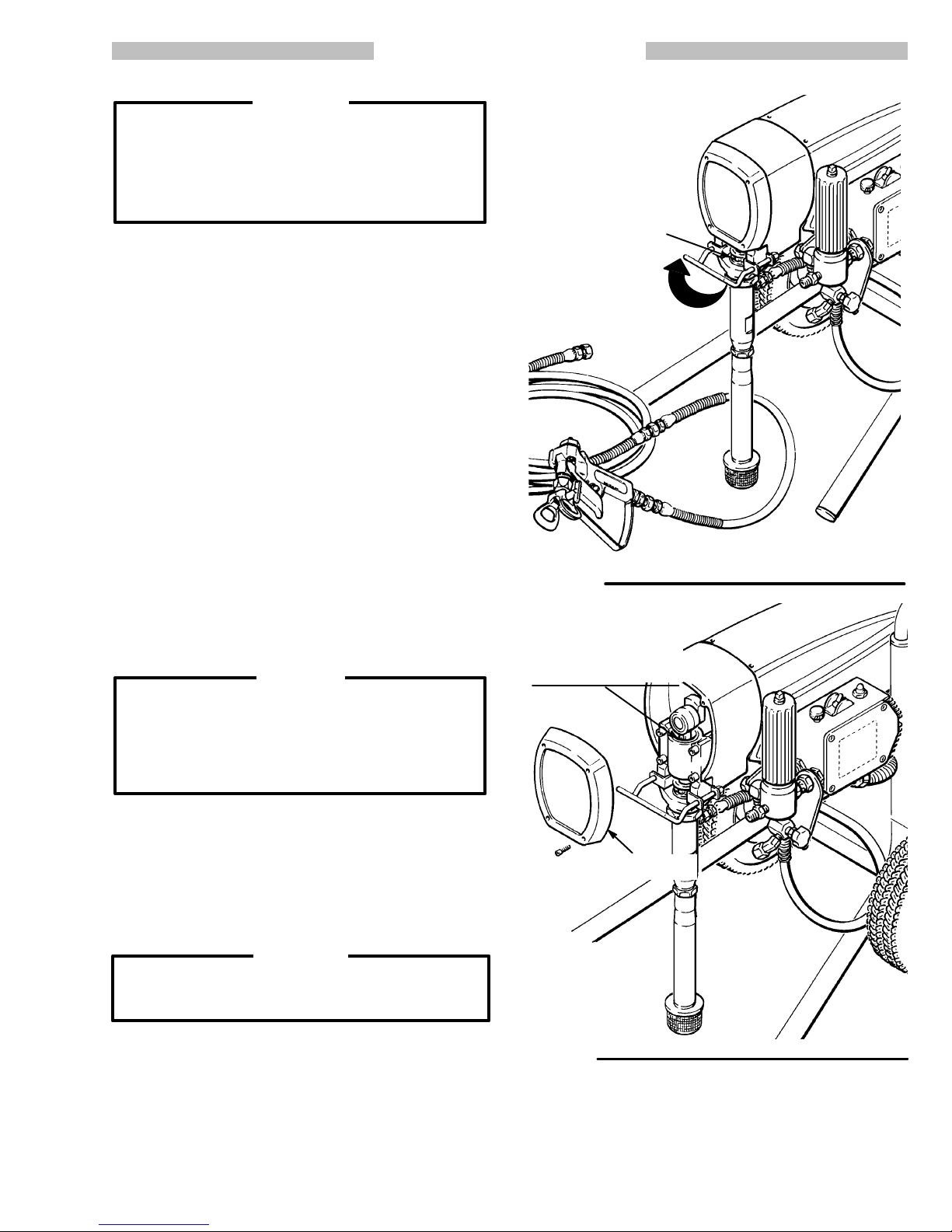
3. Fill the Packing Nut/Wet–
Cup. Fill the packing nut/wet–
cup 1/3 full with Graco Throat
Seal
Liquid (TSL), supplied.
4.
Check the Electrical Service.
a.
Be sure the electrical service is 120 V , 60 HzAC, 15
Amp (minimum) and that
the outlet you use is properly
grounded.
b.
Do not remove the third
prong of the power supply
cord,
which is the grounding
prong, and do not use an
adapter.
c. Use an extension cord
which
has 3 wires of a mini
mum 12 gauge size, a
maximum of 150 ft. long
and is rated for 15 amps.
Longer lengths may af fect
sprayer
performance.
at least 50 ft. long.
to
.
op
SHUT
MAIN HOSE
1/4 in. x 50 ft.
Fig
10–1
TIP GUARD
-
-
-
PACKING
WET–CUP
FILL 1/3 FULL
WITH TSL
1/4
npsm(m) FLUID
OUTLET NIPPLE
DO NOT INST
OFF DEVICE HERE
PRESSURE
ADJUSTING KNOB
PLUG FOR
SECONDARY
HOSE OUTLET
NUT/
ALL ANY
ON/OFF
SWITCH
PRESSURE
DRAIN V
ALVE
SHORT HOSE
3/16 in. x 3 ft.
307–786
10
Page 11
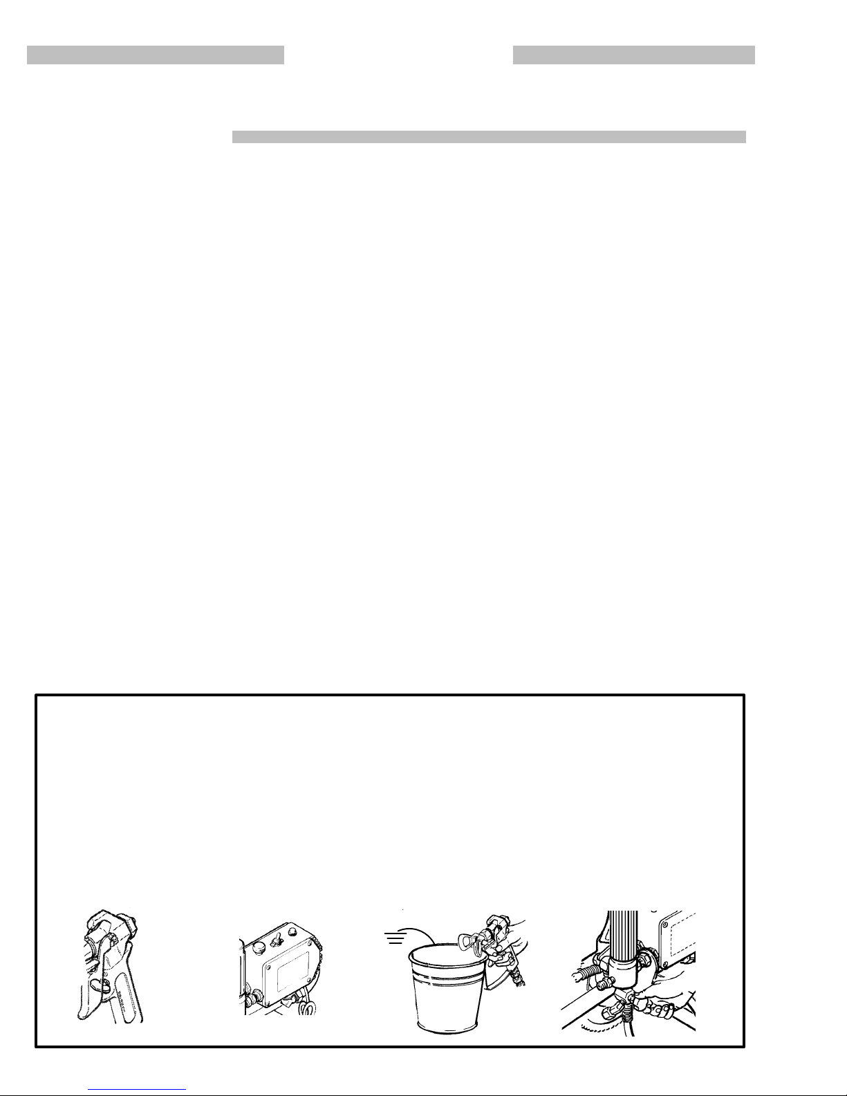
OPERATION
Pressure
To
reduce
fluid
or
on the skin, or injury
shock,
Relief Procedure
the risk of serious bodily injury
injection, splashing fluid
always follow this
WARNING
, including
or solvent in the eyes
from moving parts or electric
procedure whenever you
shut of f the sprayer , when checking or servicing
any part of the spray system, when installing,
cleaning
stop
1.
2. Turn the ON/OFF switch to OFF
3.
4.
or changing spray tips, and whenever you
spraying.
Engage the gun safety latch.
.
Unplug the sprayer
.
Disengage the gun safety latch. Hold a metal
part
of the gun firmly to the side of a
grounded
metal pail, and trigger the gun to relieve
pressure.
5.
Engage the gun safety latch.
6. Open the pressure drain valve, having a container ready to catch the drainage. Leave the
valve
open until you
are ready to spray again.
If you suspect that the spray tip or hose is completely
clogged, or that
relieved
around
pling
after following the steps above,
the tip guard retaining nut or hose end cou
and
VER
Y SLOWL
pressure has not been fully
wrap a rag
Y loosen the part to relieve
pressure gradually, then loosen completely . Now
clear
the tip or hose.
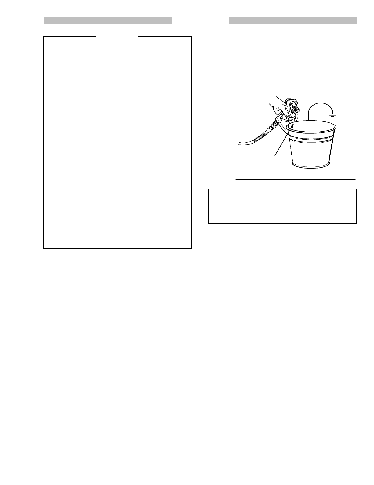
6. To prime the pump , hold a metal part of the gun
firmly against and aimed into a metal waste container.
Refer to Fig 1 1–1.
Squeeze the trigger and
hold it open, turn the ON/OFF switch to ON, and
slowly
increase the pressure setting until the sprayer
starts.
Keep
the gun triggered until all air is forced out
of
the system and the paint flows freely from the gun.
Release
the trigger and engage the gun safety
MAINTAIN
MET
AL T
CONT
FIRM
O MET
ACT WHEN
AL
FLUSHING
latch.
Fig 11–1
CAUTION
If
the pump runs without fluid in it for more than
seconds, the displacement pump packings will
damaged.
the NOTE
If the pump does not prime easily
below
.
30
be
, follow
-
NOTE: If the pump is hard to prime, place a container
under the pressure drain valve and open it.
When
fluid comes from the valve, close it. Then
disengage the gun safety latch and proceed as
in
Step 6, above.
Startup
Use this procedure each time you start the sprayer to
help
ensure the sprayer
start
it safely
.
NOTE: For the first time startup, be sure to flush the
sprayer first. Refer to page 14 for FLUSHING
GUIDELINES.
1. Close
the pressure
stalled
a secondary hose, be
curely plugged with the plug provided.
12–1.
2. Don’t install the spray tip until the pump is
primed!
3. Put the suction tube into the paint container.
4. Lower
the pressure
adjusting knob all the way counterclockwise.
to
Fig 12–1.
5. Disengage
the gun safety latch.
is ready to operate and that you
drain valve.
If you have not in
sure the adapter is se
Refer to Fig
setting
by turning the pressure
Refer
Refer to Fig 12–2.
7. Check all fluid connections for leaks . If any are
found,
follow the
ing,
to the left, before tightening connections.
8.
Install the Spray Tip and Tip Guard. Be sure the
gun safety latch is engaged.
Pressure Relief Procedure W
Refer to Fig 12–2.
stall the spray tip. If you are using the RAC IV tip
guard, refer to manual 307–848, supplied with the
gun,
for installation instructions.
9.
Adjust the Spray Pattern
-
-
a. Increase
until
spray from the gun is completely atomized.
the pressure adjusting knob setting just
To avoid excessive overspray and fogging, and
to decrease tip wear and extend the life of the
sprayer, always use the lowest possible pressure
needed to get the desired results.
b.
If more coverage is needed, use a larger tip
rather
than increasing the pressure.
c.
Test
the spray pattern. T
o adjust the direction of
the spray pattern, engage the gun safety latch
and loosen the retaining nut. Position the tip
guard
horizontally for a horizontal pattern or ver
tically
for a vertical
pattern. Then tighten the re
taining nut.
arn-
In-
-
-
307–786
11
Page 12
Cleaning a Clogged Tip
WARNING
To
reduce the risk of serious bodily injury from from
fluid
injection;
NEVER
moved.
DO NOT hold your hand, body, or a rag in front of
the
tip.
a
clear.
DO
spray
operate the spray gun with the tip guard re
spray tip when
cleaning or checking a clogged
Always point the gun toward the ground or
waste container when checking to
NOT try to “blow
sprayer
back” paint; this is NOT an air
.
see if the tip is
OPERATION
1.
2. If the spray tip does clog, release the gun trigger
-
into
3.
4.
5. If the tip is still clogged, engage the gun safety latch,
Clean the front of the tip frequently during the day’s
operation. First, follow the Pressure Relief Proce-
dure
W
arning
on page 1
1.
, en
gage the gun safety latch, and rotate the RAC IV
handle
180.
Refer to Fig 12–2.
Disengage the gun safety latch and trigger the gun
into a waste container. Engage the gun safety latch
again.
Return
the handle to the original position, disengage
the
gun safety latch, and resume spraying.
shut
of
f and unplug the sprayer
sure
drain valve to relieve pressure. Clean the spray
, and open the pres-
tip as shown in manual 307–848, supplied with the
RAC
IV
.
-
HANDLE
SPRA
TURN HANDLE 180,
DISENGAGE SAFETY
LATCH AND TRIGGER
GUN TO CLEAR CLOG
Fig
12–2
SHOWN IN
YING POSITION.
GUN
LA
ENGAGED
SECONDAR
SAFETY
TCH SHOWN
ROTA
FLUID FIL
Y HOSE PLUG
PRESSURE
ADJUSTING KNOB
TE CLOCKWISE T
CREASE PRESSURE
TER
O IN
-
ON/OFF
SWITCH
NEVER OPERA
WITH THE TIP GUARD REMOVED
Fig
12–1
307–786
12
TE THE GUN
SUCTION TUBE
PRESSURE
DRAIN VALVE
Page 13
SHUTDOWN
WARNING
To
reduce the risk of serious bodily injury
fluid
injection or splashing in the
or
injury from moving parts, always
Relief Procedure W
sure
checking, adjusting, cleaning
eyes or on the skin,
arning
on page 14 before
and
shutting down the
sprayer.
1. Check
the packing nut/wet–cup daily. First follow
the Pressure Relief Procedure W arning on page
14.
Be sure the wet–cup is 1/3 full of TSL at all times
to help prevent fluid buildup on the piston rod and
premature
wear of packings.
2. Tighten the packing nut just enough to stop
leakage.
Over tightening causes binding and exces
sive packing wear. Use a round punch or brass rod
and
light hammer to adjust the nut.
, including
follow the
Pres
Refer to Fig 13–1.
AND CARE
-
-
PACKING
TURN P
ACKING NUT
CLOCKWISE T
NUT/
WET–CUP
TIGHTEN
O
3. Clean
the fluid filter often
er
is
stored. First follow the
and whenever the spray
Pressure Relief Proce
dure W arning on page 14. Refer to manual
307–273,
Lubricate the bearing housing after every 100
4.
supplied, for the cleaning procedure.
hours of operation. Remove the front cover. Fill the
bearing housing cavity with SAE 10 non–detergent
oil.
Refer to Fig 13–2.
5. Flush
the sprayer at the end of each work day
fill
it with mineral spirits to help prevent pump corro
and
sion and freezing. Refer to FLUSHING GUIDE-
LINES
on page 14.
CAUTION
To prevent pump corrosion, and to reduce the
chance
trol in cold weather, never leave water or any type
of
can
of
6. For very short shutoff periods, leave the suction
7. Coil
of fluid
freezing in the pump or pressure con
paint in the sprayer when it is not in use.
Freezing
seriously damage the sprayer or result in a loss
pressure or stalling.
tube
in the paint, follow the Pressure Relief Proce
dure
W
arning
the hose and hang it on the
storing
it, even for overnight, to help protect the hose
from
kinking, abrasion, coupling damage, etc.
on page 14, and clean the spray tip.
hose rack
-
when
-
-
Fig 13–1
-
FILL BEARING HOUSING
CA
NON-DETERGENT OIL
AFTER EVER
HOURS OF OPERATION
-
VITY WITH SAE
Y 100
FRONT
COVER
WARNING
Refer to the warning section, HOSE SAFETY, on
page
5, for information on the hazard of using dam
aged
hoses.
-
Fig 13-2
307–786
13
Page 14
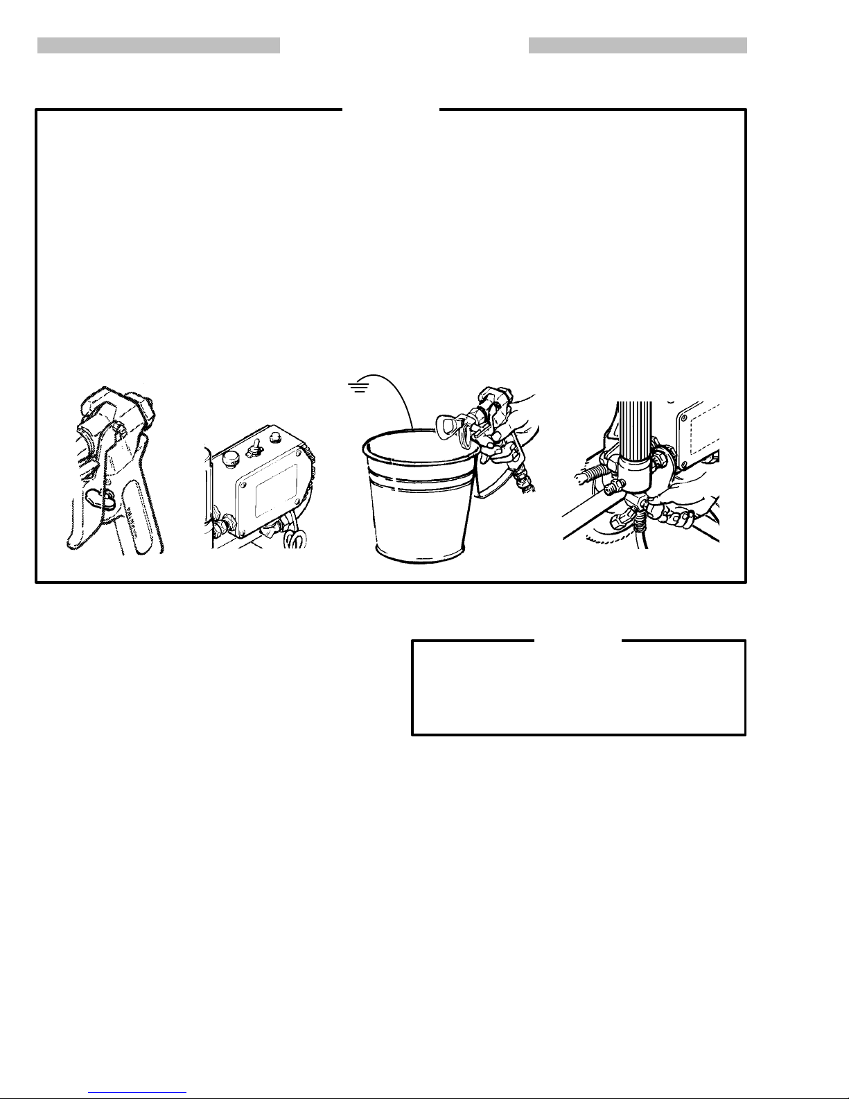
FLUSHING GUIDELINES
WARNING
Pressure
To reduce the risk of serious bodily injury , including
fluid
on the skin, or injury from moving parts or electric
shock, always follow this procedure whenever you
shut off the sprayer, when checking or servicing any
part of the spray system, when
changing
Relief Procedure
injection, splashing fluid or solvent in the eyes or
installing, cleaning or
spray tips, and whenever you stop spraying.
4.
Disengage
of the gun firmly to the side of a grounded metal
pail,
and trigger the gun to relieve pressure.
5.
Engage the gun safety latch.
6. Open
ready to catch the drainage. Leave the
until
you are ready to spray again.
the gun safety latch. Hold a metal part
the pressure drain valve, having a container
valve
open
1. Engage
2. Turn the ON/OFF switch to OFF
Unplug the power supply cord.
3.
the gun safety latch.
.
1,5 2 4 6
When to Flush
1. New
Sprayer
in lightweight oil which was left in to protect pump
parts.
Before using water–base paint
spirits followed by soapy water , and then a clean
water
flush.
. Your new sprayer was factory tested
, flush with mineral
If
you suspect that the spray
tip or hose is completely
clogged, or that pressure has not been fully relieved
after
following the
tip
guard retaining
SLOWLY
then
loosen the part to relieve pressure
loosen completely
steps above,
nut or hose end coupling and VER
. Now clear the tip or hose.
wrap a rag around the
gradually
CAUTION
NEVER
est chance it could freeze. Push the water out with
mineral spirits. W ater left to freeze in the pressure
control tube prevents the sprayer from being started
and
leave water in the sprayer if there is the slight
causes serious damage to the pressure control.
Y
,
-
Before
using oil–base paint,
only.
2. Changing Colors. Flush with a compatible solvent
such
as mineral spirits or water
3. Changing from water–base to oil–base paint.
Flush
with warm, soapy water
4. Changing from oil–base to water–base paint.
Flush with mineral spirits, followed by warm, soapy
water,
then a clean water flush.
5. Storage.
Water–base paint:
spirits
and leave the pump, hose and gun filled with
mineral spirits. Shut off the sprayer, open the pressure
drain valve to relieve pressure and leave it open.
Oil–base
sprayer, open the pressure drain valve to relieve
pressure
307–786
14
paint:
and leave it open.
flush with water , then mineral
flush with mineral spirits. Shut of
flush with mineral spirits
.
, then mineral spirits.
f the
6.
Startup after storage.
Before using water–base paint, flush out mineral
spirits
with soapy water and then a clean water flush.
When
using oil–base paint, flush out the mineral
its with the paint to be sprayed and the sprayer is
ready
to use.
spir
-
Page 15
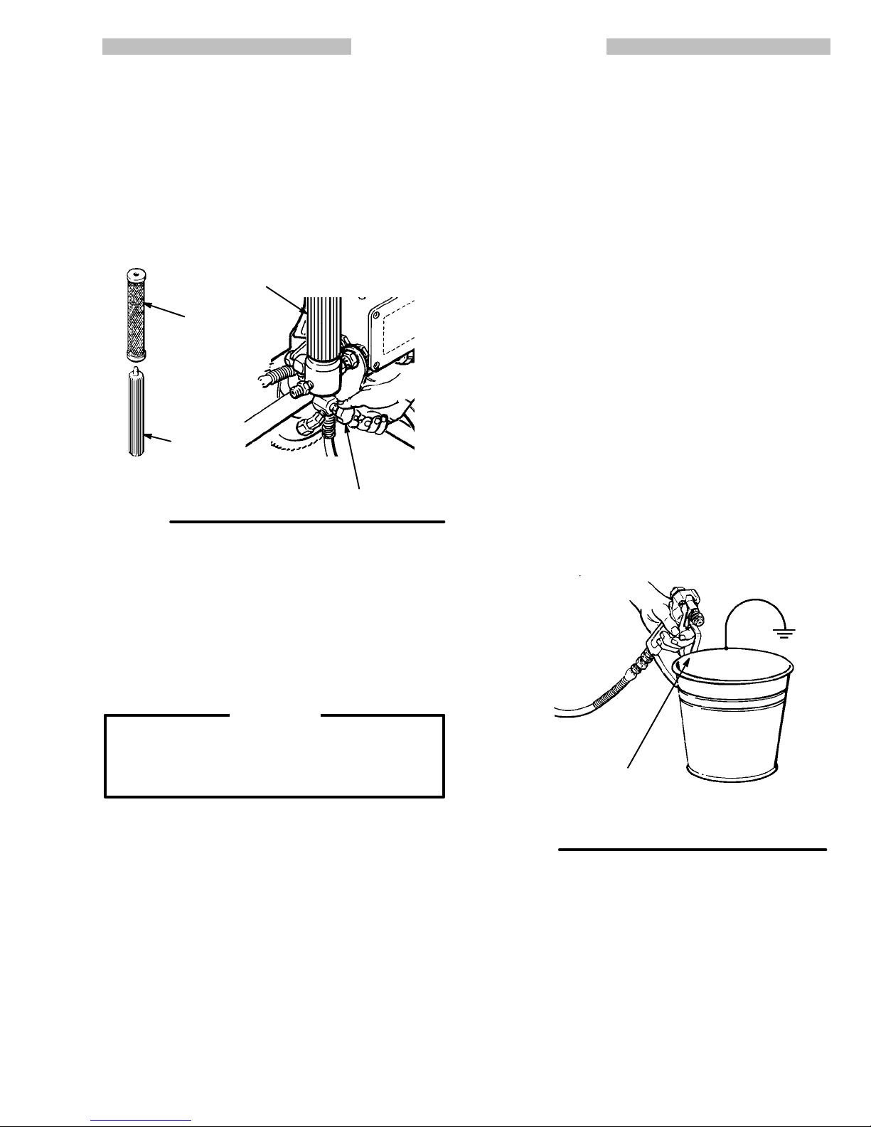
FLUSHING GUIDELINES
How to Flush
1. Follow
2. If
Fig 15–1
the
Pressure Relief Procedure W
page
14.
the sprayer has been
used before, remove the filter
bowl and screen; see manual 307–273, supplied.
Clean
the
screen separately and install the bowl with
out
the screen to flush it.
FILTER
BOWL
SCREEN
TER
FIL
SUPPORT
Refer to Fig 15–1.
PRESSURE
DRAIN
arning
V
ALVE
on
7. Hold
a metal part of the gun firmly against and aimed
into a metal waste container .
Refer to Fig 15–2.
Squeeze the trigger and hold it open, turn the ON/
OFF
switch to ON, and slowly
increase the pressure
setting until the sprayer starts. Keep the gun triggered
until all
solvent
-
and engage the gun safety latch. This procedure
air is forced out of the system and the
flows
freely from the gun. Release the trigger
helps reduce the risk of static sparking and splashing.
NOTE: If the pump is hard to prime, place a container
under the pressure drain valve and open it.
When
fluid comes from the valve, close it. Then
disengage the gun safety latch and proceed as
in
Step 7, above.
8. Remove the suction tube from the pail. Disengage
the
gun safety latch and trigger the gun to force sol
vent from the hose. Do not let the pump run dry for
more
than 30 seconds
to avoid damaging the pump
packings! Then follow the Pressure Relief Proce-
dure
W
arning
on page 14.
9. Leave the pressure drain valve open until you are
ready
to use the sprayer again. If the screen was re
moved,
screen.
10. If
a
by
lief
unscrew the filter bowl and reinstall the clean
Reinstall the bowl, hand tight only
you flushed with
water–base paint,
mineral spirits and are going to use
flush with soapy water followed
a clean water flush. Then follow the
Procedure W
arning
on page 14.
.
Pressure Re
-
-
-
3. Close
4. Pour
the pressure drain valve.
one–half gallon (2 liters) of compatible
solvent
into a grounded metal pail. Put the suction tube in the
pail.
5. Remove
the spray tip from the gun, if it is installed.
WARNING
To
reduce the risk of static sparking and splashing,
always
a
into
6. Lower the pressure setting by turning the pressure
remove the spray tip
metal part of
the gun firmly to the side of and aimed
form the gun, and hold
a grounded metal pail when flushing.
adjusting
knob all the way counterclockwise.
MAINTAIN
MET
CONT
Fig 15–2
AL T
O MET
ACT WHEN
FLUSHING
FIRM
AL
307–786
15
Page 16

TROUBLESHOOTING
Pressure
To reduce the risk of serious bodily injury , including
fluid injection, injury from splashing fluid or solvent in
the
always
sprayer, when checking or servicing any part of the
spray system, when installing, cleaning or changing
spray
1.
2. Turn the ON/OFF switch to OFF
3.
4. Disengage
Check
Relief Procedure
eyes or on the skin, moving parts or electric shock,
follow this procedure whenever you shut of
tips, and whenever you stop spraying.
Engage the gun safety latch.
.
Unplug the power supply cord.
the gun safety
of
the gun firmly to a grounded metal pail. Trigger
the
gun to relieve pressure.
latch. Hold a metal part
everything in the guide before disassembling the sprayer
WARNING
f the
GUIDE
5.
Engage the gun safety latch.
6.
Open
the pressure drain valve, having a container
ready to catch the drainage. Leave the pressure
drain
valve open until you are ready to spray
If
you suspect that the spray tip or hose is completely
clogged,
ter
or that pressure has not been fully relieved af
following the steps above,
wrap a rag around the tip
guard retaining nut or hose end coupling and VER Y
SLOWLY
loosen the part to
relieve pressure gradually
then loosen completely . Now clear the tip or hose
obstruction.
.
again.
-
,
MOTOR
TYPE
Basic
Basic Mechanical Problems
Basic Electrical Problems 1. Check
WON’T OPERA
OF PROBLEM
Fluid Pressure Problems
TE
WHAT TO CHECK
If check is OK, go to next check
1. Check
motor
(fully counterclockwise).
2. Check for a clogged spray tip. Refer to the
separate
1.
Check for frozen or hardened paint in the
pump (76) and/or pressure control tube. Using
back
2. Check displacement pump connecting rod
pin (43). It must be completely pushed into
connecting
must be firmly in groove of connecting rod.
See
3. Check for motor damage. Remove drive
housing assembly (67). See page 33. Try to
rotate
be
the pressure control knob setting. The
will not run if it is at the minimum setting
gun or tip instruction manual.
a screwdriver
of motor by hand. See page 22.
page 35.
fan by hand.
sprayer circuit breaker (309) button
sure it has not popped up.
, carefully try to rotate fan at
rod (68) and retaining spring (42)
WHA
T T
When check is not OK refer to this column
1. Slowly
2. Relieve
1.
2. Push pin into place and secure with the
3.
to
1. Depress button to reset. If circuit breaker
O DO
increase the pressure setting to see
if
the motor starts.
or
Thaw. Plug in sprayer and turn on. Slowly
increase pressure setting to see if motor
starts.
spring
Replace motor (73) if fan won’t turn.
continues
page
pressure, refer to
tip instruction manual for tip cleaning.
If it doesn’t, see NOTE 1, below
retainer
22.
.
to open, see
the separate gun
‘Electrical Short’ on
.
2. Check
3. Check extension cord for visible damage.
4. Check sprayer power supply cord (31 1) for
5. Check motor brush leads, terminals and
NOTE 1: Thaw the sprayer if water or water–based paint has
frozen
in it, due to exposure to low temperatures, by placing
in
a warm area. Do not
completely.
ing, the pump should operate. If paint hardened (dried) in the
sprayer,
be
replaced. See page 37 (pump) or 29 (pressure control).
16
If the bourdon tube was not damaged by the freez
the pump packings and/or bare pressure control must
307–786
try to start the sprayer until it has thawed
electrical supply with volt meter
should
read 105–125 V
Use
a volt meter or test lamp at extension cord
outlet to check.
visible damage such as broken insulation or
wires.
brush length. Brush length should be 1/2”
minimum.
See page 25.
AC.
it
-
. Meter
2. Reset building circuit breaker; replace
building
3.
Replace extension cord.
4. Replace
5.
Tighten
See
fuse. T
ry another outlet.
power supply cord. See page 26.
terminal screws; replace brushes.
page 25.
Page 17

MOTOR
TYPE
OF PROBLEM
WON’T OPERA
TE
WHAT TO CHECK
If check is OK, go to next check
WHA
T T
O DO
When check is not OK refer to this column
Diagnosing circuit board
indicator
condition
lamp
pump
Follow Pressure Relief Pro-
cedure W arning. Remove
gun
sure control cover. Check for
faulty condition of circuit
board
Condition A
lamps.
is red
on when board is telling
The
normal
lamp on, clear
to run.
from hose. Remove
lamps.
Both
lamps on; pump
operate and motor is not
running
pres
won’t
1.Check
2. Check G1 and G2 connections between cir-
3. Check for loose motor brush lead connec-
-
4. Check brush length which should be 1/2”
5. Check for broken or misaligned motor brush
6. Check motor brushes for binding in brush
7. Check motor armature commutator for burn
leads from bridge (308) to motor to be
sure they are securely fastened and properly
mated.
cuit
board (23) and bridge (308) for damage or
loose
terminals.
tions
and terminals. See page 25.
minimum.
NOTE: The brushes do not wear at the same
rate on both sides of the motor. Check both
brushes.
springs. Rolled portion of spring must rest
squarely
holders.
spots, gouges and extreme roughness. Remove motor cover and brush inspection
plates
See page 25.
on top of brush. See page 25.
See page 25.
to check. See page 25.
1. Replace loose terminals; crimp to leads.
Be sure male terminal blades are straight
and
firmly connected to mating part.
2. Clean circuit board male terminals. Replace loose or damaged terminals. Securely
reconnect leads.
3. Tighten
4. Replace
5. Replace spring if broken. Realign spring
6. Clean
7. Remove
terminal
if
leads are damaged. See page 25.
brushes. See page 25.
with
brush. See page 25.
brush holders. Remove carbon
small cleaning brush. Align brush leads
with
slot in brush holder to
cal
brush movement.
face
motor and have
commutator if possible.
screws. Replace brushes
with
assure free verti
motor shop resur
See page 34.
-
-
Condition B
Both
lamps of
(continued)
f
REFER TO THE WIRING
DIAGRAM ON P
AGE 18
TO IDENTIFY TP POINTS.
NOTE: Connect the volt meter
to the terminal not the wire
which
you disconnect from the
terminal.
8. Check
9. Check bridge (308) by substituting with a
1. Check
2. Check power supply cord (31 1). Disconnect
3. Check
4. Check jumper wire (306). Disconnect TP3
motor armature for
ture
tester (growler) or perform spin test. See
page
22.
good bridge or performing bridge test. See
page
23.
CAUTION:
motor armature is determined to be good. A
bad
a
good bridge.
it
has not popped up.
TP6 female (neutral) and TP1 female and
connect volt meter to these leads. Plug in
sprayer. Meter should read 105 to 125 VAC.
Unplug sprayer
and connect volt meter to TP6 female and
TP2
should
plug sprayer
and connect volt meter to TP6 female and
TP3
ter
should read 105 to 125 V
unplug sprayer
Do not perform this check until
motor armature will immediately burn out
circuit breaker (309) button
. Reconnect TP1.
ON/OFF switch (303). Disconnect
male.
Plug in sprayer and turn ON. Meter
read 105
female. Plug in sprayer and turn on. Me
to 125 V
. Reconnect TP2.
. Reconnect TP3.
shorts using arma
to be sure
AC. T
urn of
f and un
AC. T
urn of
f and
TP2
-
8.
Replace motor
9.
Replace bridge. See page 27.
1. Depress
fuse continues to open, see “Electrical
Short”,
page 22.
2. Replace
3.
Replace ON/OFF switch. See page 26.
-
4.
Replace jumper wire. See page 28.
-
. See page 34.
button to
power supply cord. See page 26.
reset. If circuit breaker or
5. Check
circuit breaker (309). Connect volt me
ter to TP6 female and TP4. Plug in sprayer
and turn ON. Meter should read 105 to 125
VAC.
T
urn of
f and unplug sprayer
.
-
5.
Replace circuit breaker
. See page 27.
307–786
17
Page 18

MOTOR
WON’T OPERA
TE
TYPE
OF PROBLEM
Condition B
Both
lamps of
REFER TO
GRAM
TP POINTS.
THE WIRING DIA
BELOW T
(continued)
f
O IDENTIFY
WHAT TO CHECK
If check is OK, go to next check
6. Check
motor thermal cutout switch. Connect
volt meter to TP6 female and TP9 female.
Plug
in sprayer and turn on. Meter should read
105
to 125 V
-
7. Check microswitch (302).Reconnect TP6
connectors.Connect
and
TP4. Meter should read 50–125 V
8. Visually
AC. Turn of
f and unplug sprayer
volt meter to TP15 male
inspect microswitch (302) button. Ad
justment stud should not depress button
when fluid pressure is zero. Depress button
with
small screwdriver; audible click
microswitch
9. Check
meter.
should
in
the sprayer
is in normal position.
microswitch (302)
continuity with ohm
Be sure sprayer is unplugged!
read zero ohms with no fluid pressure
.
10.Check all terminals for damage or loose fit.
Reconnect TP6 connectors.
WIRING
TP16
11.Check
DIAGRAM
YELLOW
BLACK
circuit board (71) by substituting with
good
board. See page 28.
303
TP1
TP15
302
BLUE
WHITE
RED
TP6
TP14
TP13
TP7
AC.
indicates
Meter
309
TP2
306
AC1
G1
AC2G2
WHA
T T
O DO
When check is not OK refer to this column
6. Allow
motor to cool. Correct cause of over
heating.
If switch remains open after
cools, check continuity between TP9 female
.
place
and TP10
motor
.
with ohmmeter
7. Clean microswitch male terminals. Replace loose or damaged terminals. Securely
reconnect leads.
-
8. Microswitch
is faulty
. Return sprayer for re
pair.
9. Microswitch
is faulty
. Return sprayer for re
pair.
10.Replace damaged terminals and reconnect securely.
a
11.
Replace circuit board. See page 28.
TP3
TP4
TP10
TP9
_
+
308
MOTOR
LEADS
motor
. If open, re
-
-
-
-
These leads have
NOTE:
interchangeable
connections:
TP9 and TP10
TP13 and TP14
TP15 and TP16
Condition
Red
Clear lamp of
C
lamps on,
f
Unplug sprayer!
1. Check circuit board (71) by removing from
box
without
for
removal procedure.
WARNING: Removing circuit board while still
wired over–rides optical detector which may
sprayer to over–pressurize, if
cause
does not function properly . T urn sprayer on
ONLY
long enough to check lamp condition,
shut
of
f immediately
WARNING: To reduce risk of electric shock,
handle board by edges only! Do not allow any
objects to come in contact with board!
metal
Plug
in and turn on sprayer
be
on now
2. Check bourdon tube flag and detector position. Reinstall circuit board (see page 29).
Turn pressure setting to maximum; flag
should extend less than half way into optical
detector
.
307–786
18
BLACK
GREEN
GROUND
WIRE
POWER SUPPLY CORD
WHITE
disconnecting wires; see page 28
microswitch
.
. Clear lamp should
. T
urn of
f and unplug sprayer
slot from the bottom.
TP8
.
MOTOR
THERMAL SWITCH
1.
Replace circuit board. See page 28.
FLAG
OPTICAL
DETECTOR
then
CIRCUIT
BOARD
2. Perform pressure control adjustment to
see
if that corrects problem. See page 30.
If not, replace bare pressure control box
See page 29.
(301).
Page 19

LOW OUTPUT
TYPE
OF PROBLEM
Low
Output
WHAT TO CHECK
If check is OK, go to next check
1.
Check for worn spray tip. 1. Follow Pressure Relief Procedure W
2.
Check
to see that pump does not continue to
stroke when gun trigger is released. Plug in
and
turn on sprayer
gun momentarily, then release and engage
safety
latch. Relieve pressure, turn of
plug sprayer.
3. Check
4. Check extension cord size and length; must
5.
6. Check
7.
electrical supply with volt meter
should
read 105–125 V
be
at least 12 gauge wire and no longer than
150
ft.
Check
G1
circuit
or
connectors. Refer to page 25.
trol
Check bridge (308) + and – leads and termi
nals to motor . Inspect wiring insulation and
terminals for signs of overheating. See page
27.
and G2 leads from bridge (308) to
board (71) for damaged
stall pressure. Refer
Adjustment on page 30.
. Prime with paint. T
f and un
AC.
or loose wires
to Pressure Con
rigger
. Meter
WHA
T T
O DO
When check is not OK refer to this column
ing
then replace tip. See
or tip manual.
2.
Service pump. See pages 37–39.
-
3. Reset building circuit breaker; replace
building
another
4. Replace with a correct, grounded extension
5. Clean circuit board male terminals. Replace
curely
-
6. Perform
page
-
7. Be
and firmly connected to female terminals.
Replace any loose terminal or damaged
wiring.
fuse. Repair electrical outlet or try
outlet.
cord.
loose or defective lead terminals.
reconnect lead terminals to board.
pressure control adjustment.
30.
sure male terminal blades are centered
Securely reconnect wires to bridge.
your separate gun
arn-
Se
See
-
8. Check
9. Check for worn motor brushes which should
10.Check
11.Check motor brushes for binding in brush
12.Check
13.Check
14. Check bridge (308) by substituting with a
for loose motor brush leads and
nals.
See page 25.
be
1/2” minimum. See page 25.
for
springs. Rolled portion of spring must rest
squarely
holders.
good
armature
See
good
See
CAUTION: Do not perform this check until
armature
mature will immediately burn out a good
bridge.
broken and misaligned motor brush
on top of brush.
See page 25.
circuit board (71) by substituting with
circuit board. See page 28.
motor armature for shorts
tester (growler) or perform spin test.
page 22.
bridge or by performing the bridge
page 23 or 27.
is determined to be good. A bad ar
termi
by using an
test.
-
8. Tighten
9.
10.Replace spring if broken. Realign spring
11.Clean brush holders, remove carbon dust
a
12.
13.
14.Replace
-
terminal
if
leads are damaged. See page 25.
Replace brushes. See page 25.
with
brush. See page 25.
with
small cleaning brush. Align brush
with
slot in brush holder to
cal
brush movement.
Replace circuit board. See page 28.
Replace motor
bridge. See page 27.
screws. Replace brushes
assure free verti
. See page 34.
lead
-
307–786
19
Page 20

NO OUTPUT
TYPE
OF PROBLEM
Motor runs and pump strokes
Motor runs but pump does not
stroke
WHAT TO CHECK
If check is OK, go to next check
1.
Check paint supply
2.
Check for clogged intake strainer
3.
Check for loose suction tube or fittings.
4. Check to see if intake valve ball and piston
ball
are seating properly
5. Check for leaking around throat packing nut
which may indicate worn or damaged packings.
See page 37.
1. Check displacement pump connecting rod
pin
(43). See page 39.
2. Check
3. Be sure
connecting rod assembly (68) for dam
age.
See page 32.
sprayer and turn on briefly to check. T
and unplug sprayer
crank in drive housing rotates; plug in
. 1.
. 2.
. See page 37.
urn of
. See page 33.
WHA
T T
O DO
When check is not OK refer to this column
Refill and reprime pump.
Remove and clean, then reinstall.
3. Tighten;
on threads if necessary.
4. Remove intake valve and clean. Check
balls
sary.
ing
pump.
5. Replace
check
or
the
1.
Replace pin if missing. Be sure retainer
spring
necting
-
2.
Replace connecting rod assembly . See
page
3.
Check
f
and replace if necessary
use
thread sealant or sealing tape
and seats
See
to remove
piston valve seat for hardened
nicks and replace if necessary
packing nut/wet-cup.
(42) is fully in groove all around con
rod. See page 39.
32.
drive housing assembly for
for nicks; replace if neces
page 37. Strain paint before us
particles that could clog the
packings. See pages 39–41. Also
. See page 33.
paint
. T
ighten
damage
-
-
-
EXCESSIVE
TYPE
OF PROBLEM
Spray pattern variations.
PRESSURE FLUCTUA
TIONS
WHAT TO CHECK
If check is OK, go to next check
1.
Be sure both G1 and G2 leads from bridge
(308) to circuit board (71) are firmly connected.
See page 28.
2.
Check maximum working pressure adjustment. Refer to Pressure Control Adjustment
on
page 30.
3.
Check bourdon tube flag and detector position. Turn pressure setting to maximum; flag
should
not drag or bind in optical detector slot
of
circuit board.
4.
Check
circuit board (71) by substituting with
good
board. See page 28.
5.
Check LOW OUTPUT section, page 19.
CIRCUIT BOARD
OPTICAL
DETECTOR
FLAG
WHA
T T
O DO
When check is not OK refer to this column
1.
Reconnect securely
2.
Perform
page
3. Carefully
tector slot to see if that corrects problem.
If not, replace bare pressure control assembly
justment
a
4.
Replace circuit board. See page 28.
pressure control adjustment.
30.
bend
(301). Perform
after reassembly
. See page 28.
flag into alignment with de
pressure control ad
.
See
-
-
307–786
20
Page 21

MOTOR
IS HOT AND RUNS
INTERMITTENTL
Y
TYPE OF PROBLEM
ELECTRICAL
TYPE
OF PROBLEM
Building circuit breaker opens
as soon as sprayer switch is
turned
on.
SHORT
CAUTION
Any short in any part of the
motor power circuit, which is
connected to the output side
of the bridge, will cause the
bridge to burn out immediately.
Correctly diagnose and
repair
all shorts before
ing
and replacing bridge.
check
WHAT TO CHECK
If check is OK, go to next check
1. Determine if sprayer was operated at high
pressure with small tips, which causes low
motor
RPM and excessive heat build up.
2. Be sure ambient temperature where sprayer
is located is no more than 90
not located in direct sun.
is
3. Determine
ized,
WHAT TO CHECK
if was sprayer turned on, pressur
but not operating for long periods of time.
F and sprayer
If check is OK, go to next check
1. Check
2. Check for missing inspection plate gasket
3. Check
-
4. Check bridge (308) by substituting with a
all electrical wiring
tion,
and all terminals
Also check wires between pressure control
and motor which are encased in conduit (1).
See
page 34.
(see page 25), bent terminal forks or other
metal to metal contact points which could
cause
a short.
motor armature for shorts. Use an ar
mature tester (growler) or perform spin test.
See
page 22. Inspect windings for burns.
good
bridge or by performing
page
24.
CAUTION: Do not check bridge until armature
is determined to
will
immediately burn out a good bridge.
for damaged insula
for loose fit or damage.
bridge test. See
be good. A bad armature
WHA
T T
O DO
When check is not OK refer to this column
1. Decrease pressure setting or increase tip
size.
2.
Move
sprayer to shaded, cooler area if pos
sible.
-
3 Turn
WHA
off sprayer whenever you stop spray
ing
for a while and relieve fluid pressure.
T T
O DO
When check is not OK refer to this column
-
1. Repair or replace any damaged wiring or
terminals.
2.
Correct faulty conditions.
-
3.
Replace motor
4.
Replace bridge. See page 27.
Securely reconnect all wires.
. See page 34.
-
-
Building circuit breaker
opens as soon as
sprayer is plugged into
outlet and sprayer is
NOT
turned on.
Sprayer circuit breaker opens
after sprayer operates for 5 to
10
minutes.
.
1. Check ‘Basic Electrical Problems’ on page
16.
2. Check
1. Check
2. Check tightness of pump packing nut. Over-
3. Check maximum working pressure adjust-
4. After
ON/OFF switch (302) See page 26.
sure the sprayer is unplugged!
wires
from switch. Check switch with
ter.
The reading should be infinity with the ON/
OFF switch OFF
CAUTION: A short
the bridge out immediately , which usually
the ON/OFF switch to fail
causes
mode.
electrical supply with volt meter
should
read 105 to 125 V
tightening tightens packings on rod, restricts
pump
action, and damages packings.
ment.
determining that there is no
tem,
reset circuit breaker button.
, and
zero with the switch ON.
in the motor circuit burns
Disconnect
in the closed
AC.
short in sys
Be
ohmme
. Meter
2. Replace
-
1.
If voltage is too high, do not operate
sprayer until corrected.
2. Loosen packing nut. Check for leaking
around throat. Replace pump packings, if
necessary.
3. Perform
page
-
4. If
pops up), replace the circuit breaker. See
page
ON/OFF switch. See page 26.
See page 37.
pressure control adjustment.
30.
circuit
breaker continues to open (button
27.
See
307–786
21
Page 22

SPIN TEST
WARNING
Before doing this procedure, follow the Pressure
Relief Procedure Warning on page 24 to reduce
the risk of a fluid injection injury , splashing in the
eyes or on the skin, injury from moving parts, or
electric shock.
For
checking armature, motor winding and brush electri
cal
continuity
Unplug the sprayer!
.
Setup
Remove the drive housing. Refer to page 33.
Remove the pressure control cover. Remove the motor
(56). Remove the fan cover (F)
shield
covers (J).
Disconnect the two leads from the motor to the bridge
(308).
Refer to Fig 22–1.
Refer to Fig 22–2.
and the inspection
Armature Short Circuit Test
Quickly
the
ing
the
Refer
turn the motor fan by hand. If there are no shorts,
motor will coast two or three revolutions before com
to a complete stop. If the motor does not spin freely
armature is shorted and
to page 34.
the motor must be replaced.
Armature, Brushes, and Motor Wiring Open
Circuit Test (Continuity)
Connect the two black motor leads together with a test
lead.
T
urn
the motor fan by hand at about two revolutions
per
second.
If
there is uneven or no
lowing:
loose
brushes.
broken brush springs, brush leads, motor leads;
brush terminal screws, motor lead terminals;
Repair parts as needed. Refer to page 25.
turning resistance, check the fol
worn
-
,
-
Fig 22-1
71
302
Fig 22-2
56
F
J
303
309
308
If
there is still uneven or no turning resistance, replace the
motor.
Refer to page 34.
307–786
22
Page 23

BRIDGE TEST
Remove the bridge from the pressure control box and
perform this test to determine if the bridge is functional.
Refer to BRIDGE RECTIFIER REPLACEMENT , page
27. Use a continuity tester, such as multi–meter set on
the
X1 ohms scale.
Perform
test,
all tests in the chart. If the bridge fails even one
it must be replaced.
Fig 23–1 shows the position of the wires on the bridge.
Using the chart at the right, connect the meter wires as
indicated
the
by the black dots for each test,
continuity
.
AC1
G1 –
AC2 G2
and then check
+
Fig 23–1
In T
ests 1, 2 and 3, there should be NO continuity
.
In Tests 4, 5 and 6, connect the + and – meter wires as
indicated, check continuity , then switch the meter wire
connections
NO
continuity one way and YES continuity the other way
and check continuity again. Y
ou should get
T
ests 7 and 8, connect the meter wires as indicated by
In
the black dots. T
wire,
and
then to the other
one
way and YES continuity the other way
CONTINUITY
NO TEST
NO
NO
YES
NO
YES
NO
YES
NO
YES
NO
YES
NO
ouch the indicated “G” wire to one meter
. Y
ou should get NO continuity
BRIDGE
WIRES
G2 G1 – + AC1 AC2
OR
OR
.
.
TEST 2
TEST 3
TEST 4
TEST
TEST 6
TEST 7
TEST 8
1
5
307–786
23
Page 24

GENERAL REP
AIR INFORMA
TION
WARNING
Pressure Relief Procedure
To
reduce the risk of serious bodily injury
fluid injection, injury from splashing fluid or solvent
in the eyes or on the skin, moving parts or electric
shock, always follow this procedure whenever you
shut
of
f the sprayer
part of the spray system, when installing, cleaning
or changing spray tips, and whenever you stop
spraying.
1.
Engage the gun safety latch.
2. Turn the ON/OFF switch to OFF
3.
Unplug the power supply cord.
4. Disengage the gun safety latch. Hold a metal
part of the gun firmly to the side of a grounded
metal pail, and trigger the gun to relieve
pressure.
5.
Engage the gun safety latch.
6.
Open the pressure drain valve, having a container ready to catch the drainage. Leave the
pressure
spray
again.
, when checking or servicing any
drain valve open until you are ready to
, including
.
If you suspect that the spray tip or hose is completely
clogged, or that pressure has not been fully
relieved
around
pling
pressure gradually, then loosen completely . Now
clear
after following the steps above,
the tip guard retaining nut or
and VER
the tip or hose obstruction.
Y SLOWL
Y loosen the part to relieve
wrap a rag
hose end cou
Tool List
Phillips screwdriver
Small flat blade
screwdriver
Needle nose pliers
Plastic mallet
Adjustable wrench
Adjustable, open–end
wrench
T
orque wrench
8. When
9. When reconnecting the wires, be sure the flat
disconnecting wires
assembly,
connectors.
blade
the
wrap–around blade of the female connector
use needle nose pliers to separate mating
of
the insulated male connector is centered in
1/4 in. hex key wrench
3/16 in. hex key wrench
5/8 in. socket wrench
3/8 in. open end wrench
1/2 in. open end wrench
3/4 in. open end wrench
7/8 in. open end wrench
High quality motor oil
Bearing grease
in
the pressure control
.
CAUTION
reduce the risk
To
be
sure to properly mate connectors, and never pull
on a wire to disconnect it. Pulling on a wire could
the connector from the wire.
loosen
of a pressure control malfunction,
10. Route wires carefully in the pressure control as-
sembly, guiding them through the legs of the U–
shaped
the
ting changes, and to avoid pinching the wires between
bourdon tube. This is to avoid interfering with
bourdon tube, which moves as
the pressure control and cover
the pressure set
.
-
CAUTION
Improper
formance
11. Keep all screws, nuts, washers, gaskets, and
electrical fittings removed during repair proce-
dures.
placement
12.
Test your repair before regular operation of the
sprayer
13. If the sprayer does not operate properly , review
the repair procedure again to verify that everything
was done correctly . If necessary , refer to the
Troubleshooting Guide, pages 16–21, to help identify
T
o reduce the risk of serious bodily injury
electric shock, DO NOT touch any moving parts or
electrical parts with your fingers or a tool while inspecting
Shut off the sprayer and unplug it as soon as you
complete
Reinstall all covers, gaskets, screws and washers
before
wire routing can result in poor sprayer per
or damage to the pressure control.
These parts are not normally provided with
assemblies.
to be sure the problem is corrected.
other possible problems and solutions.
WARNING
, including
the repair
the inspection.
operating the sprayer
.
.
-
re
-
CAUTION
Do
not
run the sprayer dry for more than 30 seconds
to
avoid damaging the pump packings.
14. Reinstall the motor shield before regular operation
of the sprayer and replace it if it is damaged. The
cover
directs cooling air around the motor to help pre
vent overheating. It can also help reduce the risk of
burns,
fire or explosion; see the
WARNING,
below
-
.
WARNING
During operation, the motor and drive housing become very hot and could burn your skin if touched.
Flammable
could
tor
shield in place during regular operation to reduce
the
risk of burns, fire or explosion.
materials spilled
cause a
fire or explosion. Always have the mo
on the hot, bare motor
-
307–786
24
Page 25

MOTOR
BRUSH
NOTE: Replace the brushes when they have worn to
less
than 1/2 in. Refer to STEP 1, Fig 25–3. Note
that
the
brushes wear dif
the
motor, so check them both. Brush Repair Kit
220–853
is available.
ferently on each side of
WARNING
Before doing this procedure, follow the Pressure
Relief Procedure Warning on page 24 to reduce
the risk of a fluid injection injury , splashing in the
eyes or on the skin, injury from moving parts, or
electric shock.
Unplug the sprayer!
REPLACEMENT
SPRING
Fig 25–2
SPRING
HOOK
BRUSH
SPRING CLIP
SPRING
CLIP
1. Remove
the motor shield (56). Remove the inspec
tion covers (J) and gaskets (K) on each side of the
motor.
Refer to Fig 25–1.
56
Fig 25–1
2. Push in the spring clip to release its hooks from the
brush holder. Pull out the spring clip. Refer to Fig
25–2.
3.
Loosen
lead
Remove
the brush lead terminal screw
away
, but leave the motor lead terminal in
and discard the brush and spring. Refer to
Fig 25–3.
4. Inspect the commutator for excessive pitting, burning
or gouging.
NOTE: A
5. Repeat
black color on the commutator is normal. Have
the
commutator resurfaced by a qualified
repair
shop if the brushes seem to wear too
for the other side.
CAUTION
When installing the brushes, follow all steps carefully. Improper installation damages parts beyond
use.
6. Place
7. Place
8. Install
9.
a new brush in the holder so the lead is in
long slot of the holder. Slide the terminal under the
terminal
connected
screw washer
at the screw
. Ensure the motor lead is still
. Refer to Fig 25–4.
the spring on the brush as shown in Fig 25–4.
Do
not install backwards
spring
clip is installed.
the
spring clip and push it down until its hooks
to avoid damage when the
catch the short slots in the housing. Refer to Fig
25–4.
Incorrect installation may jam the clip.
Repeat for the other side.
-
BRUSH
BRUSH
LEAD
TERMINAL SCREW
MOT
OR LEAD
TERMINAL
Fig
F
J
25–3
BRUSH HOLDER
SLOT
SHORT
LONG SLOT
BRUSH
SPRING
CLIP
. Pull the brush
place.
NOTE: SPRING MUST COIL
IN THIS DIRECTION
.
motor
fast.
Fig
25–4
10. Test the brushes.
a. With the sprayer OFF, turn the pressure control
knob fully counterclockwise to minimum pressure.
Plug in the sprayer
b. Turn the sprayer ON. Slowly increase the pres-
sure
until the motor comes up to full speed.
c. Inspect
for
cle
the brush and commutator contact
excessive arcing. Arcs
should not “trail” or cir
around the commutator surface.
area
-
WARNING
the
Do not touch the brushes, leads, springs or brush
holders
risk
while the sprayer is plugged in
to reduce the
of electric shock and serious bodily injury
.
CAUTION
Do not run the sprayer dry for more than 30 seconds while checking the brushes to avoid damaging the displacement pump packings.
11. Install the brush inspection covers and gaskets. In the motor shield.
stall
307–786
25
Page 26

POWER SUPPLY CORD REPLACEMENT
WARNING
Before doing this procedure, follow the Pressure
Relief Procedure Warning on page 24 to reduce
the risk of a fluid injection injury , splashing in the
eyes or on the skin, injury from moving parts, or
electric shock.
Refer to Fig 26–1.
Unplug the sprayer!
5. Reinstall
the cover
.
303
308
1. Remove the pressure control cover
2.
Disconnect
OFF
(308), and the green wire to the grounding screw
(343)
3. Loosen the strain relief bushing (328). Remove the
power
4.
Install
assembly.
the power supply cord lead from the ON/
switch (303), the white wire going
and lockwasher (327).
supply cord (31
the new cord (31
1).
1) in
the reverse order of dis
.
to the bridge
ON/OFF
SWITCH
WARNING
Before doing this procedure, follow the Pressure
Relief Procedure Warning on page 24 to reduce
the risk of a fluid injection injury , splashing in the
eyes or on the skin, injury from moving parts, or
electric shock.
Refer to Fig 26–2 except where noted.
1. Remove the pressure control cover
Unplug the sprayer!
.
343,327
-
Fig 26–1
REPLACEMENT
7.
Install the switch guard (305), aligning the internal
tab
with the groove in the threads.
8.
Powder the inside of the rubber boot (304) with talcum,
then shake excess out of boot.
9.
Install the nut and rubber boot and tighten.
10. Reconnect
reconnect
11.
Reinstall the pressure control cover
328
311
the wires to the ON/OFF switch (303)
the wire to the microswitch (302).
.
and
2.
Use
a needle nose pliers to disconnect the upper
minal
wire from
moving
3. Use
ON/OFF
4. Use a 5/8 in. socket wrench to loosen and remove
the nut and rubber boot (304) from the top of the
pressure control box. Remove the switch guard
(305).
5.
Remove the ON/OFF switch.
6.
Install
rotation ring (W) engages with the vertical groove in
the threads of the switch, and the external tab engages
box.
the ON/OFF switch (303). Refer to Fig 26–1.
pliers to disconnect the two black wires from the
the new switch so the internal tab of the anti–
with the blind hole (D) of
the microswitch (302) for ease in re
switch (303). Refer to Fig 26–1.
the pressure control
ter
-
-
Fig 26–2
304
305
D
W
303
307–786
26
Page 27

BRIDGE RECTIFIER REPLACEMENT
WARNING
Before doing this procedure, follow the Pressure
Relief Procedure Warning on page 24 to reduce
the risk of a fluid injection injury , splashing in the
eyes or on the skin, injury from moving parts, or
electric shock.
NOTE:
1.
2.
3.
4.
The
a
faulty motor
ing the bridge to prevent damaging the new
bridge.
Remove the pressure control cover
Disconnect
propriate
Outside the pressure control box are two screws
(331).
the
motor
Slide
the bridge out.
Slide
the slotted end of the new bridge (308) into the
box so the lockwasher (333) on the rear screw (331)
is
IN FRONT of
low.
Unplug the sprayer!
most common cause of bridge failure is
.
Check the motor before replac
.
all wires from the
terminals, using needle nose pliers.
Loosen,
but don’t remove the screw nearest
. Then loosen and remove the front screw
the bridge. Refer to the DET
bridge (308) at the ap
AIL be
5.
Install the front screw (331), lockwasher (333) and
nut
(332). Make sure the bridge is flush with the side
of
the box and tighten the screws securely
.
CAUTION
The
lockwashers (333) must be
to avoid overheating which will result in bridge
-
failure.
6.
Be
is centered in the wrap–around blade of the female
connector
connections
.
Route
movement of the bourdon tube, circuit board, or
control
-
7.
Refer to the DET
Connect all wires. Carefully route the wires.
AIL in Fig 27–1.
CAUTION
sure the flat blade of the insulated male connector
when the connections are made.
may cause the sprayer to malfunction.
all wires carefully to avoid interference with the
box cover which could cause a malfunction.
Reinstall the pressure control cover
in front of the bridge
Improper
.
303
310
Fig 27–1
CIRCUIT BREAKER REPLACEMENT
WARNING
Before doing this procedure, follow the Pressure
Relief Procedure Warning on page 24 to reduce
the risk of a fluid injection injury , splashing in the
eyes or on the skin, injury from moving parts, or
electric shock.
Unplug the sprayer!
306
309
308
BRIDGE INST
SLOTTED
END
4. Use a 5/8 in. socket wrench to loosen the nut and
boot
(310) on the circuit breaker button.
5. Push
6.
down on the top of the circuit breaker and pull
it
out of the box.
Install the new circuit breaker in the reverse order
ALLA
TION DET
LOOSEN THIS SCREW
BUT DO NOT REMOVE
333
332
AIL
LOOSEN AND
REMOVE
308
331
.
Refer to Fig 27–1.
1.
Remove the pressure control cover
2. Use
3. Disconnect the single black wire (306) from the cir-
a small screwdriver to slide the terminal adapter
off
the circuit breaker terminal.
cuit
breaker (309) to the ON/OFF switch (303).
7.
Reinstall the pressure control cover
.
Do
not alow the circuit breaker contacts to touch the
bourdon tube, which will cause a short. T
circuit breaker nut firmly to prevent the circuit
breaker
from turning.
CAUTION
.
ighten the
307–786
27
Page 28

CIRCUIT
BOARD
WARNING
Before doing this procedure, follow the Pressure
Relief Procedure Warning on page 24 to reduce
the risk of a fluid injection injury , splashing in the
eyes or on the skin, injury from moving parts, or
electric shock.
Refer to Fig 28–1 and 28–2.
1. Remove the pressure control cover
2.
Turn the pressure control knob to the minimum setting
to release spring tension on the board. Check to
be sure only three or four threads of the pressure
control knob shaft are exposed below the pressure
adjustment
fer
to Fig 28–1.
Unplug the sprayer!
.
nut (S). Loosen the nut, if necessary. Re
REPLACEMENT
6.
Reconnect all wires. Refer to the wiring diagram in
Fig
28–2. Ease the pin (330) into the retainer
PRESSURE
CONTROL KNOB
CIRCUIT
BOARD
-
Fig
28–1
.
330
S
CAUTION
Step 2 is essential to reduce the risk of damaging
the
circuit board while removing or installing it.
3. Disconnect ALL wires from the board, including the
two
heavy black wires. Pay close
connections
4.
Pull
out the black plastic–tipped pin (330). Push the
bottom
trol
and carefully slide the board out.
5.
Reinstall
as
it was removed.
are made. Refer to Fig 28–2.
of the circuit board toward the wall of the con
the new board in the box at the same angle
BLUE
WHITE
YELLOW
BLACK
RED
attention to where
CAUTION
Be
sure the flat blade of the insulated male connec
tor
is centered in the wrap–around blade of the
male
connector when the connections are made.
Route
all wires carefully to avoid interference with
the
circuit board, bourdon tube, or pressure control
fe
-
-
cover.
precautions are essential to reduce the
-
These
of
a malfunction.
7.
Perform the PRESSURE CONTROL ADJUST-
MENT,
page 30, if you installed a new board.
risk
71
330
Fig 28–2
307–786
28
BLACK
GREEN
GROUND
WIRE
POWER SUPPLY CORD
WHITE
AC1
AC2G1G2
_
+
MOTOR
THERMAL SWITCH
MOTOR
LEADS
Page 29

PRESSURE CONTROL REPLACEMENT
WARNING
Before doing this procedure, follow the Pressure
Relief Procedure Warning on page 24 to reduce
the risk of a fluid injection injury , splashing in the
eyes or on the skin, injury from moving parts, or
electric shock.
Refer to Fig 29–1 except where noted.
1.
Disconnect
dary fluid hose, if used. Disconnect the fluid hose
(70) at the displacement pump nipple (40) and the
pressure
2.
Loosen the filter bracket nut (38).
3.
Hold the hex of the pressure control adapter (341)
firmly with a 3/4” open end wrench. Use an adjustable wrench to unscrew the swivel union (39), and
then
remove the fluid filter (66).
4.
Remove
the
four motor leads. Refer to Fig 28–2.
5.
Remove
28.
Unplug the sprayer!
the main fluid hose (101) and the secon
control nipple (344).
the pressure control cover (63). Disconnect
the circuit board and retain it. Refer to page
Remove the conduit (1).
6.
7.
Remove the three screws (8) and lockwashers (10)
and
nuts (1
move
8. Remove
bracket
1) located below the pressure control. Re
the pressure control.
the screws (22) holding the back mounting
(64) to the pressure control.
9. Install the new pressure control assembly in the re-
-
verse order of disassembly . Reinstall the conduit
seal (29) around the wires in the conduit connector
(345) to prevent motor contamination from entering
the
control. See the DET
AIL below
.
10. Perform the PRESSURE CONTROL ADJUST-
MENT, page 30, before regular operation of the
sprayer.
CAUTION
Do
not allow
the new pressure control assembly . Turning it can
damage the sensitive bourdon tube. Hold the
adapter firmly with a 3/4” open end wrench while
screwing
the adapter (341) to turn while installing
in the swivel union (39).
-
10
11
Fig 29–1
38
12
40
22
341
344
39
70
CAUTION
Do
not allow the adapter
(341) to turn at any time.
64
345
36,63
8
1
DETAIL
Shows position of conduit
seal (29) in conduit
connector (345)
29
345
307–786
29
Page 30

PRESSURE
CONTROL ADJUSTMENT
WARNING
USE EXTREME CAUTION WHEN PERFORMING THIS ADJUSTMENT PROCEDURE to reduce the risk of a
fluid injection injury or other serious bodily injury which can result from component rupture, electric shock, fire,
explosion,
This
MAXIMUM WORKING PRESSURE and sets the
overpressurization switch (microswitch) to approximately
Perform this procedure whenever the pressure control
assembly is removed and reinstalled or replaced,
or
a new circuit board is installed.
Improper adjustment can cause the sprayer to overpressurize
plosion.
the maximum working pressure, resulting in poor
sprayer
or moving parts.
procedure sets the sprayer to3000 psi (210 bar)
3600 psi (242 bar).
and result in component rupture, fire or ex
It may also prevent the sprayer from obtaining
performance.
NEVER
ing pressure of 3000 psi (210 bar ) by performing
these
of
ponent rupture, fire or explosion. To perform this adjustment,
porarily
sure.
Use
3000 psi (210 bar) MAXIMUM WORKING PRESSURE. A used, under–rated hose could develop a
high
try to
increase the sprayer’s maximum work
adjustments in any other
the sprayer at higher pressures may result in com
however
increased above the normal working pres-
a
new
50 ft (15.2 m) spray hose rated for at least
pressure leak or rupture.
, the sprayer pressure
way
. Normal operation
must be
tem-
-
-
NOTE: The following tools and equipment are required
for
this procedure.
3/8 in. nut driver or 3/8 in. socket wrench
1/4 in. open end wrench
7/16 in. open end wrench
0 – 5000 psi, oil–filled test gauge, Part No. 102–814
Pail of clean water
Mineral spirits
NEW 3000 psi (210 bar) high pressure spray hose,
Part No. 214–915
1.
Follow
the
Pressure Relief Procedure W
page
24.
2. Refer
to the above list
Remove the plug (A) from the top
ed.
and install the fluid-filled pressure gauge. Refer to
Fig
30–1. Connect the gun to the
connect
the hose to the sprayer outlet.
A
of tools and equipment need
new
arning
of the fluid filter
test hose and
on
4. Place
5. Be
NOTE:
6.
7. Turn the pressure control knob (B) to the
-
Adjust the Overpressurization Switch
8. With the spray gun triggered,
9. Slowly turn the pressure control knob to the maxi-
the pump suction tube in a pail of clean water
sure the gun safety latch is engaged.
For Steps 5 through 18, refer to Fig 31–1.
Plug in the sprayer
setting
(fully counterclockwise), and turn the
ON. THE DISPLACEMENT PUMP SHOULD NOT
CYCLE
If
it does cycle
bottom
driver through the opening, and unscrew the
pressure
stops
of the pressure control. Insert a 3/8 in. nut
running.
.
,
remove the plug (17) from the
adjustment nut (T) just until the sprayer
slowly
sure control knob clockwise just until the sprayer
starts.
Prime the pump and hose.
mum
setting. While watching the red light
cuit board and the pressure gauge, turn the nut (T)
slowly
to increase pressure until the red light goes
out and the gauge reads between 3400 –3800 psi
(238
– 266 bar).
minimum
sprayer
turn the pres-
on the cir
.
-
Fig 30-1
3. Remove the pressure control cover
307–786
30
.
If the red light does not go out by 3800 psi
(266
bar),
loosen the nut (P) and adjust the stud
(Q)
until the light goes out.
If
the red light goes out before 3400 psi (238
bar), loosen the nut (P) and adjust the stud (Q)
until
the light goes out between 3400 – 3800 psi
(238
– 266 bar).
10. T
ighten the nut (P) if it was loosened in Step 9.
11. Trigger
ger and engage the safety latch. Repeat Step 9 to
verify
12.
Install the pressure control cover
the gun to relieve pressure. Release the
your results.
.
trig
-
Page 31

PRESSURE
CONTROL ADJUSTMENT
Maximum Working Pressure Adjustment
13. Turn the sprayer OFF . Disengage the gun safety
latch.
T
rigger the gun into a grounded waste contain
er until pressure is relieved. Engage the gun safety
latch.
17. Turn the pressure control knob to the minimum setting.
Release the gun safety latch and trigger the
into
-
a grounded waste container until
lieved.
Engage the gun safety
the pressure to verify that the maximum working
pressure
is set at 3000 psi (210 bar).
latch. Slowly increase
pressure is re
gun
-
14. Use
15. With the pressure control knob at the
16.
the 3/8 in. nut driver to turn the pressure adjust
ment
nut (T) counterclockwise one full turn.
minimum
ting,
turn the sprayer ON.
Slowly
to the maximum setting and hold it there. Use a 3/8
in.
sure adjustment nut (T) clockwise until the gauge
reads
turn the pressure control
nut
driver or socket wrench to slowly turn the pres
EXACTL
Y 3000 psi (210 bar).
knob (B) clockwise
B
P
Q
71
T
set-
-
-
CAUTION
To prevent pump corrosion,
the
pump, hose
to close the drain valve, first. Use the lowest
pressure necessary to flush. Follow the Pressure
Relief Procedure Warning on page 24. Leave the
mineral
ready
18. Install
spirits in the pump to protect it
to spray again.
the plug (17) in the bottom of the pressure con
trol. Remove the gauge assembly and reinstall the
plug.
Flush out the water with mineral spirits.
and gun with mineral spirits. Be sure
flush the water out of
until you are
-
Fig 33–1
INSERT
WRENCH HERE
T
O ADJUST NUT (T)
17
307–786
31
Page 32

BEARING
HOUSING &
CONNECTING ROD REPLACEMENT
WARNING
Before doing this procedure, follow the Pressure
Relief Procedure Warning on page 24 to reduce
the risk of a fluid injection injury , splashing in the
eyes
or in the skin, injury from moving parts or elec
tric
shock.
BEARING GREASE
Unplug the sprayer!
P
ACKING WITH
C
67
E
8. Assemble
the connecting rod (68)
and bearing hous
-
ing (69).
9. Clean the mating surfaces of the bearing and drive
-
housings.
10. Align
fully
the
holes in the bearing housing (69). Push the bear
the connecting rod with the crank (E) and care
align the locating pins in the drive housing with
-
ing housing onto the drive housing or tap it into place
with
a plastic mallet.
23
68
OIL
B
TORQUE TO
175 IN–LB
(19 N.M)
49
25
69
24
F
42
43
47
70
40
76
Fig 34–1
NOTE: Stop
the sprayer at the bottom of its stroke to get
the crank (E) in its lowest position.To lower the
crank
manually
fan
with a screwdriver
, carefully rotate the blades of the
.
1. Remove the front cover (49). Hold a wrench on the
pump intake valve and unscrew the pump suction
tube.
Disconnect the short hose (70) from the pump.
2. Push up the retaining spring (42). Push the pin (43)
out the rear
3.
Loosen the pump jam nut (47). Unscrew the dis-
.
placement pump (76).
CAUTION
DO
NOT use the bearing housing screws (25) to try
to
align or seat the
drive
housing will not align properly and will result in
premature
bearing wear
11. Install the screws (25) and lockwashers (23) in the
bearing housing. T ighten the screws evenly to
175
in–lb (19 N.m).
FACE
BEARING
HOUSING
Fig 34–2
12. Screw
the displacement pump 3/4 of the way into the
bearing
housing (69). Hold the pin (43) up to the pin
hole in the connecting rod (68). Screw in the pump
until the pin slides easily into the hole. Back of f the
pump until the top threads of the pump cylinder are
flush
with
the face of the bearing housing and the out
let adapter (A) is facing back. Push the retaining
spring (42) into the groove all the way around the
connecting
about
70 ft–lb (95 N.m) –
and
a light hammer
bearing housing; the bearing and
.
43
68
OF
42
69
47
TORQUE TO
70 ft–lb
(95 N.M)
rod. Tighten the locknut (47) very tight –
with a 2 in. open end wrench
.
See Fig 34–2.
-
4. Remove the four screws (25) and lockwashers (23)
from
the bearing housing (69).
5. Lightly
tap the lower rear of the bearing housing (69)
with
a plastic mallet to loosen it from the drive hous
ing
(67). Pull the bearing housing and the connecting
rod
assembly (68) straight of
f the drive housing.
6. Remove the pail bracket assembly (F) and reinstall
it
on the new bearing housing.
7. Inspect
the crank (E) for excessive
wear and replace
parts as needed. Evenly lubricate the inside of the
bronze
ally
32
bearing (B) with high quality motor oil. Liber
pack the roller bearing (C) with bearing grease.
307–786
-
-
WARNING
Be sure the retaining spring (42) is firmly in the
groove all the way around, to prevent the pin (43)
from
working loose due to vibration.
If the pin works loose, it or other parts could break
off
due to the force of the pump action. These parts
could
be projected through the air and result in seri
ous
bodily injury or property damage, including dam
age
to the pump connecting rod or bearing housing.
13. Install
the front cover (49). Connect the suction tube
(86)
and short hose (70) to the pump.
See Fig 34–2.
See Fig 34–1.
-
-
Page 33

DRIVE HOUSING REPLACEMENT
WARNING
Before doing this procedure, follow the Pressure
Relief Procedure Warning on page 24 to reduce
the risk of a fluid injection injury , splashing in the
eyes
or in the skin, injury from moving parts or elec
tric
shock.
Refer to Fig 33–1
1.
Remove the front cover (49). Remove the motor
shield (56).
2.
Remove the four screws (25) and lockwashers (23)
from
3.
Lightly
with
ing
ing
4.
Remove the two screws (26) and lockwashers (20)
from
5. Remove the two screws (13) and lockwashers (20)
from
6. Remove the two screws (16) and lockwashers (20)
from
7. Tap the drive housing (67) with a plastic mallet to
loosen it from the front end bell (R), then pull it
straight
Unplug the sprayer!
.
the bearing housing.
tap the lower rear of the bearing housing (69)
a plastic mallet to loosen it from the drive hous
(67). Then pull the bearing housing and connect
rod assembly straight of
the recess of the drive housing
the rear of the motor front end bell (R)
the upper rear of the motor front end bell (R).
of
f.
f the drive housing.
-
CAUTION
DO
NOT allow the gear cluster (51) to fall when re
moving
if
front
DO NOT lose the thrust balls (9) located at each
end
tween
grease, usually stays in the shaft recesses, but
could be dislodged. If caught between gears and
not removed, the balls will seriously damage the
drive
ings
-
8. Liberally apply bearing grease to the gear cluster
-
9. Place the bronze–colored washer (67b) THEN the
10.
the drive housing (67). It is easily damaged
dropped. The gear may stay engaged in either the
end bell or the drive housing.
of the gear cluster (51) or
gears. The ball,
housing. If the balls are not in place, the bear
will wear prematurely
(51).
Use approximately 6 oz. of the grease supplied
with the drive housing replacement kit.Check to be
sure
the thrust balls (9) are in place.
silver–colored washer (67a) on the shaft protruding
from
the big gear in the drive housing (67). Align the
gears
and push the new drive housing straight onto
the front end bell and locating pins.
Starting
to
at Step
reassemble the sprayer
which is heavily covered with
7 and working backwards, continue
allow them to fall be
.
.
-
-
-
49
24
25
23
69
E
67
67b
67a 9
51
26
20
34
16
20
R
56
34
13
9
20
Fig 33–1
307–786
33
Page 34

MOTOR REPLACEMENT
WARNING
Before doing this procedure, follow the Pressure
Relief Procedure Warning on page 24 to reduce
the risk of a fluid injection injury , splashing in the
eyes
or in the skin, injury from moving parts or elec
tric
shock.
Unplug the sprayer!
Refer to FIg 35–1 unless otherwise instructed.
1.
Remove the motor shield (56).
2.
Remove
the
3.
Loosen
sure
4.
Swing
elbow (31).
5. Remove the conduit seal (29) from around the conduit
leads
the pressure control cover (63). Disconnect
four motor leads.
the conduit connector nut (345)
control (75).
the conduit (1) away from the pressure control
elbow coming into the control box. Pull the motor
through the elbow
, one at a time.
at the pres
CAUTION
Always pull the motor leads one at a time to avoid
loosening
connection
6.
Loosen
the conduit (1) away from the motor . Pull the leads
through
7.
Unscrew the connector elbow from the motor
the terminals, which could result in a
and poor sprayer performance.
the connector nut (31) at the motor and
the conduit, one at a time.
-
bad
pull
.
CAUTION
DO
NOT allow the gear cluster (51) to fall when re
moving
if
the
DO NOT lose the thrust balls (9) located at each
end
tween
grease, usually stays in the gear recesses, but
could be dislodged. If caught between gears and
not removed, the balls will seriously damage the
drive
-
ings
14. While
15. Place the new motor on the frame and align the
16.
17. Place the bronze–colored washer (67b) and THEN
the drive housing (67). It is easily damaged
dropped. The cluster may stay engaged in either
front end bell or the drive housing.
of the gear cluster (51) or
gears. The ball,
housing. If the balls are not in place, the bear
will wear prematurely
supporting
tipping, remove the four screws (8), washers (87),
lockwashers
the
frame. Lift of
frame mounting holes. Install the screws (8),
washers
Liberally grease the gear cluster (51) and pinion gear
(B)
and pack all bearings in the motor front end bell.
Check
the
silver–colored washer (67a) on the shaft protrud
ing
from the big gear in the drive housing (67).
(1
(87), lockwashers (1
to be sure the thrust balls (9) are in place.
which is heavily covered with
the motor to keep the sprayer from
1) and nuts (10) holding the motor to
f the motor
allow them to fall be
.
.
1) and nuts (10),
-
-
-
tightly
.
-
8.
Pull the wires through the elbow
9.
Remove the front cover and screws (49, 24).
10. Remove
the
11. Remove
the
12. Remove
the
13. Use a plastic mallet to gently tap the displacement
pump
(67)
away
the two screws (26) and washers (20) from
recess of the drive housing,
the two screws (13) and washers (20) from
lower rear of the motor front end bell (73b),
the two screws (16) and washers (20) from
upper rear of the motor front end bell (R).
(76) from the rear to loosen
from the front end bell (R). Pull the drive housing
from the end bell.
, one at a time.
the drive housing
18. Align the gears and push the drive housing (67)
straight
19. Starting
to
NOTE: Use a turning motion on the conduit (1) when
20. Install the conduit seal (29) around the wires in the
conduit elbow (345) at the pressure control to keep
contaminants from entering the motor conduit. See
the
21.
Install the motor shield and pressure control cover
onto the front end
at Step
reassemble the sprayer
feeding
Detail in FIg 35–1.
12 and working backwards, continue
wires through it.
bell (R) and locating pins.
.
.
307–786
34
Page 35

WIRING DIAGRAM
302
BLUE
WHITE
YELLOW
BLACK
RED
303
BLACK
GREEN
GROUND
WIRE
POWER SUPPLY CORD
WHITE
309
AC1
AC2G1G2
_
+
MOTOR
THERMAL SWITCH
16
20
56
MOTOR
LEADS
34
DETAIL
Shows
position of
conduit seal (29) in
conduit connector
29
345
(345)
49
24
25
23
69
R
8
87
67
67a 9
51
67b
31
E
75
36,63
13
9
20
11
10
70
20
1
345
SEE
DET
ABOVE
AIL
26
40
Fig 35–1
307–786
35
Page 36

DISPLACEMENT PUMP REPAIR
WARNING
Before doing this procedure, follow the Pressure
Relief
Procedure W
arning
on page 24 to reduce
the risk of a fluid injection injury , splashing in the
eyes or on the skin, injury from moving parts or
electric
shock.
NOTE: Packing Repair Kit 222–588 is available. In the
text and drawings, reference numbers with an
asterisk, i.e., (210*), indicate the parts included
in the repair kit. For the best results, use all the
new
parts in the kit, even if the old ones still
look
good.
69
DETAIL
42
INT
AKE V
OF
ALVE
224
43
219
47
220
*221
40
70
204*
*202
2. Clean
3. Remove
4. Use
and inspect the parts
placing
included
eded,
parts as needed. Always use
in the Repair Kit. If no further service is ne
reassemble the intake valve.
for wear or damage, re
the new o–ring
the packing nut (216) and plug (205).
to
Fig 37–3.
a plastic mallet to tap the piston rod (224) down,
Refer
then pull the rod out through the bottom of the
cylinder.
5. Remove the throat packings (207, 213) and glands
(208,
209).
Refer to Fig 37–3.
NOTE: Whenever
ing
or repair
you
disassemble the pump for clean
, remove the sleeve. A special sleeve
removal tool is available. Order Graco Part No.
222–586.
Do not use any other type of tool.
WARNING
Always use the special
sleeve
removal tool to re
-
A
move the sleeve. Other
removal methods could
cause the pump to rup-
B
ture, resulting in serious
bodily
injury
. If the
sleeve
cannot
ly using the tool, return
the
your
be removed easi
sleeve
and cylinder to
Graco distributor for
219
removal.
-
-
-
223
86
Fig
36–1
Removing the Pump
Refer to Fig 36–1.
1. Flush the pump, if possible, and relieve pressure
again.
Stop the pump with the piston rod (224) in its
lowest
position, if possible.
2. Hold the wrench on the pump intake valve (223) to
keep
the pump from loosening and remove the suc
tion tube (86).
NOTE:If
3.
repairing only the
Disassembling
intake valve assembly
the Pump
, Steps 1 and 2.
Remove the hose (70) from the nipple (40).
4. Push the retaining spring (42) up. Push out the pin
(43).
5. Loosen
the
the locknut (47) and unscrew the pump from
bearing housing (69).
Disassembling the Pump
1. Unscrew the intake valve (223) from the cylinder
(219). Remove the o-ring (202), ball guide (220),
stop
pin (221) and ball (204) from the valve.
Fig
36–1.
307–786
36
, go to
Refer to
6. Screw the large nut (B)
of the tool into the top of
the cylinder (19). Screw
the rod (A) to push
down
the sleeve out. Remove
the tool.
Refer to Fig
36–2.
7. Clamp
the flats of the piston rod in a vise. Loosen
retaining nut (211). Unscrew the piston valve (222)
from
the rod. Remove all
(222).
Refer to Fig 37–1.
Reassembling the Pump
NOTE: Alternate
-
NOTE:
1. Check
2. Stack
in Fig 37–1. The lips of the throat “V” packings
must face down, against pressure. The lips of
the piston “V” packings must face up, against
pressure. The lips of the U–cup seal (3) face
down. Incorrect installation damages the packings
and results in pump leaking.
Soak leather packings in oil before using them.
the outside of the piston rod (224) and the in
side of the sleeve (218) for scoring or scratches. If
these
parts are damaged, new packings will not seal
properly.
Replace these parts if needed.
the backup washer (214), seal (203*),
gland
(215*), alternate the
then male gland (210*) onto the piston valve (222).
Refer
to Fig 37–1.
Fig 36–2
the
parts from the piston valve
leather and plastic packings as shown
-
female
packings (212*,206*), and
Page 37

DISPLACEMENT PUMP REPAIR
3. Tighten
ton
Note
the packing retaining
nut (21
valve (222) to 19 ft –lb (27 N.m).
the alignment
of the
piston (222) to the pack
1) onto the pis
ing retainer nut (21 1). Maintain this alignment
through
4. Place
to
Steps 5, 6 and 7.
the ball (225) on the piston valve (222).
Fig 37–1.
Refer
CAUTION
Step
5 is critical.
avoid
5. Apply
damaging the packings by overtightening.
one drop of
Follow the procedure carefully to
adhesive, supplied, to the threads
of the piston valve. Then hand tighten the valve assembly
tacts
into the piston rod just
the rod.
Refer to Fig 37–1.
until the nut (21
1) con
224
225*
TORQUE TO
10.5 in-lb (1.2 N.m)
to seat the packing,
and then back of
tighten finger tight.
LEA
THER
POLY
LIPS F
Fig
37–1
6. Place
the flats at the top of the rod in a vise.
f and
*206
*212
ACE UP
211
APPLY ONE DROP
OF SEALANT T
THESE THREADS
O
210*
215*
203*
LIPS FACE DOWN
222
7. Use a wrench to CAREFULLY tighten the nut (211)
onto
the piston rod to 19 ft–lbs (25 N.m).
Refer to Fig
37–2.
Use two wrenches to maintain the alignment mentioned
in Step 7, above.
TORQUE
ONTO ROD TO
DO NOT ALLOW NUT
(211) TO MOVE
INSTALLING
NUT
19 ft–lb
(27 N.m)
WHEN
PIST
ONTO ROD
ON
211
224
-
10. Coat the piston rod and packings with oil. Carefully
slide the assembly INT O THE T OP OF THE
-
SLEEVE.
NOTE: The
Refer
tapered end of the sleeve is the bottom of
to Fig 38–1.
11. Place a new o–ring (202*) firmly in the cylinder
groove.
Refer to Fig 37–3.
THROA
205
216
*209
47
*207
LEATHER
LIPS MUST
FACE DOWN
*208
DET
PISTON PACKINGS
*202
219
218
*210
*206
LEATHER
LIPS MUST
F
ACE UP
*203
U–CUP SEAL
LIPS MUST
FACE DOWN
212*
POLY
LIPS
F
215*
214*
DET
AIL OF
T P
ACKINGS
213*
POLY
LIPS MUST
F
ACE UP
AIL OF
MUST
ACE UP
it.
Fig 37–2
8. One
at a time stack the male
the
packings (213*,207*), and then
gland
(9), into the top of the cylinder (219).
Fig 37–3.
9. Install
loose
the packing
for now.
Refer to Fig 37–3.
nut (216) and plug (205), but leave
gland (208*), alternate
install the female
Refer to
*202
Fig 37–3
223
TORQUE TO:
67 ft-lb
(90 N.m)
307–786
37
Page 38

DISPLACEMENT PUMP REPAIR
Be sure the retaining spring (42) is firmly in the
CYLINDER
SLEEVE
groove
prevent
to
If the pin works loose, it or other parts could break
off due to the force of the pumping action. These
parts could be projected through the air and result
in
ing
housing.
of the connecting rod, all the way around, to
it from working loose due to vibration. Refer
Fig 38–2.
serious bodily injury or property damage, includ
damage to the pump, connecting rod or bearing
WARNING
-
PISTON
ASSEMBLY
TAPERED
END
Fig 38-1
12. Slide the sleeve/piston rod assembly INT O THE
BOTTOM OF THE CYLINDER . This is to prevent
packing damage during reassembly .
Refer to Fig
38–1.
13. Screw
14.
15. Screw
down the cylinder locknut (47) until
tight
at the bottom of the external cylinder threads.
it is finger
Place flats of the intake valve (223) in a vise. Install
a
new o-ring (202*). Screw the pump
valve. Torque to 67 ft–lb (90 N.m).
cylinder into the
Refer to Fig 37–3.
the displacement pump about 3/4 of the way
into
the bearing housing (69). Hold the pin (43) up to
the
pin hole in the connecting rod assembly (68) and
continue screwing in the pump until the pin slides
easily into the hole. Back off the pump until the top
threads of the pump cylinder are flush with the face
of the bearing housing and the outlet nipple (40) is
straight
groove
back. Push the retaining spring (42) into the
all the way around the connecting rod. T
ighten the locknut (47) very tight–about 70 ft-lb (97
N.m)–with
mer.
a 2 in. open–end wrench and a light ham
Refer to Fig 38–2.
CAUTION
If the locknut (47) loosens during operation, the
threads of the bearing housing (69) will be damaged.
Be sure to tighten the locknut firmly
16. Tighten the packing nut (216) just enough to stop
leakage,
1/3
but no tighter
full with Graco TSL.
. Fill the wet–cup/packing
43
68
F
ACE OF
BEARING
HOUSING
47
TORQUE TO
70 ft–lb
-
Fig 38–2
(95 N.m)
.
nut
42
69
307–786
38
Page 39

PARTS
PTFE
PTFE
DRA
WING & LIST – DISPLACEMENT PUMP
Model 222–580, Series A
Sleeved
Includes items 202 to 225
REF
NO. PART NO. DESCRIPTION QTY
202 110–165* P
203 107–093*
204 105–445* BALL; sst 1
205 179–810 PLUG 1
206 178–939* V–P
207 178–940* V–P
208 178–942*
209 178–943*
210 178–944*
211
212 178–964* V–PACKING, plastic 3
213 178–965* V–PACKING, plastic 3
214 181–338* WASHER, backup 1
215 178–969*
216
218
219 185–21
220
221 178–938*
222
223
224
225 105–444*
*Supplied in repair kit 222–588.
Displacement Pump
SEAL, u–cup, polyurethane
GLAND, male
GLAND, female
178–945
179–809
185–213
185–214
218–036
222–437
222–438
GLAND, male
NUT
GLAND, female
NUT
SLEEVE, cylinder 1
1
CYLINDER 1
GUIDE, ball 1
PIN, ball stop
VAL
VAL
ROD, piston 1
BALL
ACKING, o–ring,
ACKING, leather
ACKING, leather
, hex, retaining
, packing
VE, piston
VE, intake
2
1
2
2
1
1
1
1
205
216
209*
224
225*
211
1
1
1
1
1
1
*207
213*
208*
*212
210*
206*
REPAIR
Must
be purchased separately
KIT 222–588
.
Includes:
REF
NO. DESCRIPTION QTY
202 PACKING,
203
SEAL, u–cup, polyurethane
204 BALL; sst 1
206 V–P
207 V–P
208
GLAND, male
209
GLAND, female
GLAND, male
210
212 V–PACKING, plastic 3
213 V–PACKING, plastic 3
214 WASHER, backup 1
215
GLAND, female
221
PIN, ball stop
225
BALL
o–ring,
ACKING, leather
ACKING, leather
SLEEVE REMOVAL TOOL
Must
be purchased separately
.
219
215*
203*
214*
1
1
2
2
1
1
1
202*
222
220
*221
1
1
1
218
204*
202*
223
NOTE: Be
222–586 Sleeve
sure you
order the correct tool for your pump.
Removal T
ool, for pump 222–580.
307–786
39
Page 40

PARTS
DRA
WING – UPRIGHT SPRAYER
750 Sprayers with Upright
Ultra
Model
231–033, Series C
Includes items 1–90
Basic Sprayer
Model 231–042, Series B
Includes items 1 – 90, 100 – 102
Complete Sprayer
67
68
59
IDENTIFICATION
LABEL
49
69
23
25
42
Cart
W
ARNING LABEL
51
67b
26
32
60
67a
20
IDENTIFICATION
WARNING
41
16
20
73
9
9
10
11
LABEL
10
46
56
34
LABEL
8
87
58
78
77
31
13
20
57
IDENTIFICATION
LABEL
348590
34
3
Ref
62
48
89
37
Ref
78
77
35
24
61
SEE P
ON P
43
47
76
ARTS
AGE 39
86
53
40
70
38
12
72
40
66
50
33
64
Ref 64
Ref
8
14
21
19
22
8
63
44
INSIDE
55
OUTSIDE
LABEL
LABEL
36
1
39
75
SEE PARTS ON P
AGE 44
45
Ref
70
307–786
40
74
Page 41

PARTS LIST – UPRIGHT SPRAYER
Ultra 750 Sprayers with Upright Cart
Model 231–033, Series C
Includes
Basic Sprayer
REF
NO. PART NO. DESCRIPTION QTY
1 065–099 CONDUIT
3 100–020 LOCKWASHER, 3/8” 2
8 100–057 SCREW,
9 100–069
10
11 100–214
12 100–322 LOCKWASHER,
13 100–643 SCREW,
14 101–242 RING,
16
17 101–754 PLUG,
19 104–811 HUBCAP 2
20 105–510
21 106–062 WHEEL,
22
23 106–115 LOCKWASHER,
24 107–209 SCREW,
25 107–210 CAPSCREW,
26 107–218
27 107–258 TIP,
29 107–447 SEAL,
31 108–460
32 108–662 NUT,
33 108–691
34 108–865
35 109–032 SCREW,
36 110–037 SCREW,
37 110–243 RING,
38
39 155–665 UNION,
40 162–453 NIPPLE,
41 176–250* LABEL,
42 176–817 SPRING,
43
44 177–762* LABEL,
45 178–034*
46 178–934*
47 178–941 NUT,
48 179–777 BUTTON,
49 179–899 COVER,
50 179–945 ADAPTER,
51 179–961 GEAR REDUCER 1
52 180–041
53 181–072
55 181–608 LABEL,
56 222–693 SHIELD,
57 181–636 LABEL,
58 181–637 LABEL,
59 181–638 LABEL,
60 183–035 BRACKET 2
61 183–037 HANGER,
items 1–90
s
pecify
5/16–18 x .25”
100–188
100–644
106–078 SCREW,
150–513
176–818 PIN, straight,
BALL,
NUT
LOCKWASHER,
shakeproof;
no. 1/4–20 x 1.00”
SCREW,
no. 1/4–20 x 0.75”
LOCKWASHER, spring,
no. 6–24 x 1/2”, type “c”
unc–3a x 1–1/2”
CAPSCREW
CONNECTOR, conduit,
PLUG, tubing
SCREW
no. 8 x 3/8”
NUT
swivel x 3/8 npt(m)
0.3125” dia x 1.023”
TAG,
LABEL,
1/4–18 npt (m x f)
PIN, straight,
STRAINER 1
includes
of items 41, 57, and 58
,
electrical
length when ordering
hex head no.
0.8 ft
steel; 1/4” dia.
,
heavy
hex; 5/16–18 unc–2a
7/16”
socket
spring; 5/16”
external
head
retaining 2
socket head,
pipe,
see
page 44
semi–pneumatic 2
mach, ovhd, thd frmg;
mach, filh; no. 8–32 x1”
sch; 3/8–16
,
grip,
conduit,
retainer 2
,
jam;
sch;
see
page 44
see
,
mach;
pan head;
mach, pnh
mach,
retaining 2
pnhd
7/16”
adapter; 3/8” npsm
1/4
npt(m) x 1/4 npsm
WARNING 1
retaining
hdls;
1/4”
spring, 3/8”
1/4–20 x 2.75”
page 44
45
1
W
ARNING 1
W
ARNING 1
WARNING 1
hex
snap 2
housing 1
elbow,
special;
see
page 44
identification
motor
ID,
motor cover
ID,
motor cover
ID,
front cover
pail
, left
, right
8 of item 34, and one each
10
Model 231–042, Series B
Includes
Complete Sprayer
REF
NO. PART NO. DESCRIPTION QTY
62 183–194 SLEEVE 2
63 183–995 COVER,
64
65 206–994 THROAT SEAL LIQUID,
66 214–570 FLUID
7
2
7
7
67 220–369 DRIVE HOUSING
1
67a 178–967 .WASHER,
2
67b 107–089 .WASHER,
68
69
70 218–083
2
1
71 218–405
6
72 100–509 PLUG
73 222–376**
4
4
4
73a 107–267 .TERMINAL,
73b 107–504 .TERMINAL,
4
73c
2
74 222–198
1
2
75 220–455 PRESSURE CONTROL ASSY
76 222–580
2
77 222–554 HANDLE,
78 222–555 FRAME,
85 185–384 BRACKET 2
4
86 185–386 TUBE,
4
87 107–194 WASHER 4
89 183–350 WASHER 2
1
90 110–240 CLIP 2
100 210–541 HOSE,
1
2
101 214–701 HOSE,
1
1
102 220–955 SPRAY GUN
1
*Extra
**Motor Brush Repair Kit 220–853 is available.
Order separately
1
1
1
1
1
1
1
1
items 1 – 90, 100 – 102
183–365 BRACKET,
Includes
see manual 307–273 for parts
includes
and one of item 9
218–034
ROD, CONNECTING 1
218–035 HOUSING,
HOSE, grounded,
cpld 1/4 npsm (f); 29” (715 mm);
spring guards both ends
BOARD, CIRCUIT;
MOTOR, ELECTRIC
includes
(shown on page 45)
and one each of items 9 and 41
596–421
.TERMINAL,
VAL
see
DISPLACEMENT PUMP
see
cpld 1/4 npsm(f); 50 ft (15 m)
spring guards both ends
cpld 1/4 npsm(f); 3 ft (.9 m);
spring guards both ends
see
pressure control
mounting
FIL
TER
one of item 40
replaceable items 67a and 67b
silver–colored 1
bronze–colored 1
BEARING
, pipe 1/4 npt
replaceable items 73a to 73c
female 2
female
VE,
parts on page 44
page 39 for parts
manual 307–614 for parts
wire, female, snap–on
PRESSURE DRAIN
cart
sprayer
suction 1
grounded, nylon; 1/4” ID;
grounded,
warning tags and labels available free.
.
102
nylon;1/4” ID
1
15V 1
nylon; 3/16” ID;
100 101
8
OZ
1
1
1
1
1
1
1
1
1
1
1
1
1
1
1
1
1
1
1
307–786
41
Page 42

Ultra
750 Sprayer
with Lo-Boy Cart
Model 221–120, Series C
Includes items 1 to 99
Model 221–130, Series B
Includes items 1 to 102
98
PARTS
37
97
DRA
WING – LO-BOY SPRAYER
58
57
46
34
83
92
5
20
W
ARNING LABEL
WARNING
LABEL
73
16
ID LABEL
ID LABEL
41
56
34
90
ID
LABEL
49
24
59
SEE P
53
91
23
25
43
AGE 39
92
68
69
42
47
76
REF 97
67
99
93
Ref
70
9
67b
WARNING
26
51
20
38
67a
46
LABEL
11
10
77
12
9
50
62
72
10
11
40
30
8
87
34
3
85
31
11
10
13
8
20
11
78a
8
33
35
22
21
89
63
4
8
64
14
INSIDE
LABEL
OUTSIDE
19
LABEL
66
44
55
1
39
45
70
36
75
SEE PARTS
ON P
AGE 44
74
307–786
42
100 101
102
Page 43

PARTS LIST – LO-BOY SPRAYER
Ultra 750 Sprayers with Lo-Boy Cart
Model 221–120, Series C
Includes
Basic Sprayer with Lo-Boy Cart
REF
NO. PART NO. DESCRIPTION QTY
1 065–099 CONDUIT
3 100–020 LOCKWASHER, 3/8” 2
4 185–407 SPACER 1
5 183–769 TUBE,
8 100–057 SCREW,
9 100–069
10
11 100–214
12 100–322 LOCKWASHER,
13 100–643 SCREW,
14 101–242 RING,
16
17 101–754 PLUG,
19 104–811 HUBCAP 2
20 105–510
21 106–062 WHEEL,
22
23 106–115 LOCKWASHER,
24 107–209 SCREW,
25 107–210 CAPSCREW,
26 107–218
27 107–258 TIP,
29 107–447 SEAL,
30 108–982 CONNECTOR,
31
33 105–521 PLUG,
34 108–865
35 183–275 SPACER,
36 110–037 SCREW
37 103–117 RING,
38
39 155–665 UNION,
40 162–453 NIPPLE,
41 176–250* LABEL,
42 176–817 SPRING,
43
44 177–762* LABEL,
45 178–034*
46
47 178–941 NUT,
49 179–899 COVER,
50 179–945 ADAPTER,
51 179–961 GEAR REDUCER 1
52 180–041
53 183–770
55 181–608 LABEL,
56 222–693** MOTOR SHIELD KIT
57 181–636 LABEL,
items 1–99
s
pecify
5/16–18 x .25”
100–188
100–644
106–078 SCREW,
108–460
150–513
176–818 PIN, straight,
178–934*
BALL,
NUT
LOCKWASHER,
shakeproof;
no. 1/4–20 x 1.00”
SCREW,
no. 1/4–20 x 0.75”
LOCKWASHER, spring,
no. 6–24 x 1/2”, type “c”
unc–3a x 1–1/2”
CAPSCREW
CONNECTOR, conduit,
SCREW
no. 8 x 3/8”
NUT
swivel x 3/8 npt(m)
0.3125” dia x 1.023”
TAG, WARNING 1
LABEL,
1/4–18 npt (m x f)
PIN, straight
STRAINER 1
includes
of items 41, 57, and 58
,
electrical
length when ordering
suction 1
hex head no.
0.8 ft
steel; 1/4” dia.
,
heavy
hex; 5/16–18 unc–2a
7/16”
socket
spring; 5/16”
external
head
retaining 2
socket head,
pipe,
see
page 44
semi–pneumatic 2
mach, ovhd, thd frmg;
mach, filh; no. 8–32 x1”
sch; 3/8–16
,
see
sch;
page 44
see
grip,
conduit,
1/4”
spring, 3/8”
1/4–20 x 2.75”
page 44
tube 1
45
1
tubing
,
mach;
pan head;
wheel 2
,
mach,
retaining 2
,
jam;
pnhd
7/16”
adapter; 3/8” npsm
1/4
npt(m) x 1/4 npsm
WARNING 1
retaining
hdls;
W
ARNING 1
WARNING 1
hex
housing 1
elbow,
special;
see
page 44
identification
8 of item 34, and one each
ID,
motor cover
, left
11
11
11
10
Model 221–130, Series B
Includes
Complete Sprayer with Lo-Boy Cart
REF
NO. PART NO. DESCRIPTION QTY
58 181–637 LABEL,
59 181–638 LABEL,
62 178–566 SLEEVE 2
63 183–995 COVER,
64
65 206–994 THROAT SEAL LIQUID,
66 214–570 FLUID
2
67 220–369 DRIVE HOUSING KIT
1
67a 178–967 .WASHER,
67b 107–089 .WASHER,
2
68
69
70 220–680 HOSE,
2
1
71 218–405
6
72 100–509 PLUG,
73 222–376
4
4
73a 107–267 .TERMINAL,
4
73b 107–504 .TERMINAL,
73c
4
2
74 221–077 VALVE,
75 220–455 PRESSURE CONTROL ASSY
1
2
76 222–580**
77 183–288 HANDLE,
2
78 220–678 FRAME KIT
78a 221–119 FRAME, cart 1
4
83 176–920 HOSE,
85 185–384 BRACKET 2
1
87 107–194 WASHER 4
89 154–636 WASHER 2
1
90 110–240 CLIP 2
1
91 103–473 STRAP,
1
92 103–927 CLAMP,
93 110–229 UNION,
97 183–281 HOSE,
1
98 178–342 CLIP
99 156–823 UNION,
100 210–541 HOSE,
1
101 214–701 HOSE,
1
102 220–955 SPRAY GUN
1
1
*Extra
**Repair Kits A
1
1
items 1 – 102
ID,
motor cover
ID,
front cover
183–365 BRACKET,
Includes
see manual 307–273 for parts
includes
and one of item 9
218–034
CONNECTING ROD KIT 1
pressure control
mounting
FIL
TER
one of item 40
replaceable items 67a and 67b
silver–colored 1
bronze–colored 1
218–035 BEARING HOUSING KIT 1
grounded,
pipe, 1/4 npt
replaceable items 73a to 73c
female 2
female
wire, female, snap–on
PRESSURE DRAIN
parts on page 44
page 39 for parts
cart
items 78a and
suction, 30” (762 mm)
wire
tie
hose,
1.25” ID
adapter 1
drain 1
,
spring 2
swivel,
grounded, nylon; 1/4” ID;
grounded,
manual 307–614 for parts
596–421
cpld 1/4 npsm (f); 29” (715 mm)
BOARD, circuit;
ELECTRIC MOTOR KIT
includes
(shown on page 45)
and one each of items 9 and 41
.TERMINAL,
see
DISPLACEMENT PUMP
see
Includes
items 14, 33, 35, 37, 62, 77, 89
cpld 1/4 npsm(f); 50 ft (15 m)
spring guards both ends
cpld 1/4 npsm(f); 3 ft (.9 m);
spring guards both ends
see
warning tags and labels available free.
vailable.
Motor Brushes: 220–853
Pump Packings: 222–588
, right
nylon;1/4” ID
1
15V 1
1/4 npt(m) x 1/4 npt(f)
nylon; 3/16” ID;
8
OZ
1
1
1
1
1
1
1
1
1
1
1
1
1
1
1
1
1
1
2
2
1
1
1
1
307–786
43
Page 44

PARTS
DRA
WING & LIST – PRESSURE CONTROL
PRESSURE
Includes all items listed below
CONTROL ASSEMBL
, except the terminals.
Y 220–455
The terminals are included with the circuit board (item
71).
The terminals listed in
wiring
diagram on page 45.
REF
NO. PART NO. DESCRIPTION QTY
302 180–043 ,MICROSWITCH 1
303 105–679 .ON/OFF switch 1
304 105–659 .BOOT, switch 1
305 107–255 .GUARD, locking 1
306 218–168 JUMPER WIRE 1
308 218–170
309 107–256 CIRCUIT BREAKER 1
310 107–254 BOOT, circuit breaker 1
31
1 218–169 CORD, power supply 1
312 107–268
314 107–267
315 107–293
316 107–264
317 107–396
318 107–262
319 107–260
320 107–266
321 103–885
322 103–886
323 107–265
324 107–263
RECTIFIER, bridge
ADAPTER, terminal
TERMINAL, female
TERMINAL, female
TERMINAL, male
TERMINAL, male
TERMINAL, female
TERMINAL, female
TERMINAL, female
TERMINAL, male
TERMINAL, female
TERMINAL, female
TERMINAL, female
this parts list are shown on the
Part
numbers for items 17,
73c
are shown in the drawings below and on page 45 are
given
on page 41 and 43.
REF
NO. PART NO. DESCRIPTION QTY
325 102–799
327 157–021 LOCKW
328 108–295 BUSHING, strain relief 1
331 101–273 SCREW
332 100–179 NUT, hex, mscr
1
333 100–718 LOCKW
334 178–797**
335 178–035**
1
336 107–261
1
2
337 107–503
338 107–504
1
341 157–350
1
342 100–840 ELBOW
1
1
343 100–035 SCREW
1
344 162–453
1
345 108–460 CONNECT
3
1
1
*Extra warning labels available free.
TERMINAL, ring
no. 10–24 x 5/8”
shakeproof, no. 10
LABEL, W
LABEL, W
TERMINAL, male
TERMINAL, female
TERMINAL, male
ADAPTER, 3/8 npt(m) x 1/2 npt (m)
pan hd; no. 8 x 5/16”
NIPPLE, 1/4 npt(m) x 1/4 npsm
27, 29, 52, 71, 73a, 73b and
ASHER, no. 8, internal
, mach; flat hd;
, no. 10–24 thd
ASHER, internal,
ARNING 1
ARNING 1
, street; 1/4 npt(m x f)
, mach; slotted
OR, conduit
1
1
2
2
2
2
1
1
1
1
1
1
1
301
REF 71
302
52,27
341
342
(REAR
)
344
The
terminals listed in this
parts list are shown in the
wiring diagram on page 45.
17
343,327
334,335
LABELS
325
328
311
304
305
303
310
29
345
309
308
331,332,333
306
DETAIL
Shows
duit seal (29) in conduit
connector (345)
position of con
29
345
-
307–786
44
Page 45

WIRING
DIAGRAM
BLUE
WHITE
YELLOW
BLACK
RED
CIRCUIT
BOARD 218–405
316
318
317
302
336
Ref
27,52
73a
319
323
324
320
303
306
322
337
AC1
AC2G1G2_+
309
312
321
(73c)
73b
308
323
73a
BLACK
GREEN
GROUND
WIRE
POWER SUPPL
WHITE
Y CORD
314
323
MOTOR
THERMAL
SWITCH
307–786
45
Page 46

ACCESSORIES
SUCTION TUBE KIT
208–259
55 gallon (200 liter) size
Includes:
REF
NO. PART NO. DESCRIPTION QTY
1 156–589 UNION 1
2 214–961
3 156–591 ELBOW 1
4 156–593 PACKING 1
5 100–220 THUMBSCREW
6 176–684 ADAPTER 1
7 156–592 TUBE 1
8 159–100 RETAINER 1
9 161–377 SCREEN 1
10 159–101 NUT 1
HOSE, 3/4 ID; nylon; 6 ft
2
7
1
5
6
8
9
10
SUCTION TUBE KIT
208–920
5 gallon (19 liter) size
Includes:
REF
NO. PART NO. DESCRIPTION QTY
1 101–818 CLAMP
1
2 160–327 UNION, 90
3 170–705 ADAPTER 1
4 170–706 HOSE, 48” 1
5 170–957 TUBE, 1
6 181–072 STRAINER 1
,
6
2
3
1
1
4
1
5
307–786
46
Page 47

TECHNICAL
Power
Requirements
W
orking Pressure Range
Cycles/Gallon
Maximum Delivery
Power
Cord
Inlet
Paint Strainer
Outlet Paint Filter
Pump Inlet Size
Fluid
Outlet Size
Wetted Parts:
Displacement Pump
Filter
NOTE: Delrin
(liter)
.
. . . . . . . . . . . . .
.
. . . . . . . . . .
.
. . . . . . . . .
.
. . . . . . . . . . . . . . . . .
.
. . . . . . . . . . . . . . .
DA
TA
120 V
. . . . . . . . . . . . . . . . . .
.
. . . . . . . .
.
. . . . . . . . . . . . . . . . . . . . . . . . . . .
.
. . . . . . . . . . . . . .
.
. . . . . . . . . . . . . . .
.
. . . . . . .
Aluminum, Carbon steel, Stainless Steel,
1
phase, 15 amp minimum
0–3000 psi (0 – 210 bar)
No. 14 AWG, 3 wire, 8’6” (2.6 m)
Stainless
Stainless
0.85 GPM (3.2 liter/min)
16 mesh (1
Steel Screen, reusable
60 mesh (250 micron)
Steel Screen, reusable
3/4 npt(m) with 20 ID chamfer
1/4 npsm from fluid filter
Carbon steel, Polyurethane,
Polyethylene, Delrin, Leather
AC, 60Hz,.
260 (70)
190 micron)
DIMENSIONS
W
eight (dry w/o packaging)
Height 28
Length 26.0
Width 22.5
.
. . . . . . . . . . . . . . . . . . . . . . . . . . . . . . . .
.
. . . . . . . . . . . . . . . . . . . . . . . . . . . . . .
.
. . . . . . . . . . . . . . . . . . . . . . . . . . . . . . .
.
. . . . . . . . . . . . . . . .
95 lb (43 Kg)
in. (71
in. (660 mm)
in. (572 mm)
GRACO PHONE NUMBERS
TO
PLACE AN ORDER
Graco,
7:00 a.m. to 6:00 p.m. Central T
1–800–423–8594 T
1–612–623–6921 in Minnesota
FOR
TECHNICAL ASSIST
or
answers about the application of Graco equipment, call the
following
number
1–612–623–6922 in Minnesota
, contact your Graco
ANCE
,
service repair information
, 7:00 a.m. to 6:00 p.m. Central T
1–800–543–0339 T
oll Free
distributor
ime:
oll Free
, or call
ime:
1 mm)
307–786
47
Page 48

WARRANTY
THE
GRACO WARRANTY AND DISCLAIMERS
warrants all equipment manufactured by it and bearing its name to be free from
Graco
ship
on
the date of sale by an authorized Graco distributor to the original purchaser for use. As purchaser’s sole remedy
for
breach of this warranty
equipment
power
Gas–Hydraulic
chanical
ated
This
tion,
proven
train on EH & GH sprayers, which will be repaired
(GH) and Gas Mechanical (GM) sprayers and for thirty–six months from the date of sale for Electric–Me
(EM) and Electric–Hydraulic (EH) Sprayers. This warranty applies only when the equipment is installed, oper
and maintained in accordance with Graco’
warranty does not cover
misapplication, abrasion, corrosion, inadequate or improper maintenance, negligence, accident, tampering, or sub
, Graco will, for a period of twelve months from the date of sale, repair or replace any part of the
defective, with the exception of defects in parts on the drive train/gear box on EM and GM sprayers or
or replaced for twenty–four months from the date of sale for
s written recommendations.
, and Graco shall not be liable for
, any malfunction, damage or wear caused by faulty installa
stitution of non–Graco component parts. Nor shall Graco be liable for malfunction, damage or wear caused by the incom
patibility
design,
with Graco equipment of structures, accessories, equipment or materials not supplied by Graco, or the improper
manufacture, installation, operation or maintenance of structures, accessories, equipment or materials not sup
defects in material and workman
-
-
-
-
-
-
-
plied by Graco.
warranty is conditioned upon the prepaid return of the equipment claimed to be defective to an authorized
This
distributor
tive
does
may
for verification of the claim. If the claimed
parts. The equipment will
be returned to the original purchaser transportation prepaid. If inspection of the equipment
defect is verified, Graco will repair or replace free of charge any defec
not disclose any defect in material or workmanship, repairs
include the costs of parts, labor and transportation.
will be made at a reasonable charge, which charges
Graco
-
DISCLAIMERS AND LIMITATIONS
THE
TERMS OF THIS W
OTHER WARRANTIES (EXPRESS OR IMPLIED), INCLUDING W
FOR
A PARTICULAR PURPOSE, AND OF ANY NON–CONTRACTUAL LIABILITIES, INCLUDING PRODUCT LIABILITIES, BASED
ON
NEGLIGENCE OR STRICT LIABILITY
OR
LOSS IS EXPRESSL
PURCHASE
SALE.
PRICE. ANY ACTION FOR BREACH OF W
ARRANTY CONSTITUTE PURCHASER’S SOLE AND EXCLUSIVE REMEDY AND ARE IN LIEU OF ANY
. EVER
Y EXCLUDED AND DENIED. IN NO CASE SHALL GRACO’S LIABILITY EXCEED THE
Y FORM OF LIABILITY FOR DIRECT
ARRANTY
ARRANTY OF MERCHANT
MUST BE BROUGHT WITHIN TWO (2) YEARS OF THE DA
ABILITY OR W
, SPECIAL OR CONSEQUENTIAL DAMAGES
ARRANTY OF FITNESS
AMOUNT OF THE
TE OF
EQUIPMENT NOT COVERED BY GRACO WARRANTY
GRACO
MAKES NO W
PARTICULAR
MANUFACTURED
etc.)
are subject to the warranty
making
PURPOSE, WITH RESPECT TO ACCESSORIES, EQUIPMENT
any claim for breach of these warranties.
ARRANTY
BY GRACO.
, AND DISCLAIMS ALL IMPLIED W
These
items sold, but not manufactured by Graco (such as electric motor
, if any
, of their
manufacturer
ARRANTIES OF MERCHANT
, MA
TERIALS, OR COMPONENTS SOLD BUT NOT
. Graco will provide purchaser with reasonable assistance in
ABILITY AND FITNESS FOR A
, switches, hose,
Factory
Branches:
Atlanta, Dallas, Detroit, Los Angeles, W
Subsidiary and Affiliate Companies:
GRACO INC.P.O. BOX 1441
PRINTED
307–786
48
est Caldwell (N.J.)
Canada; England; Switzerland; France; Germany; Hong Kong; Japan
MINNEAPOLIS, MN
IN U.S.A. 307–786 7–86 Revised 5–89
55440–1444
 Loading...