

Graco ULTRA 600 231–307 Series A, ULTRA 600 231–325 Series A Instructions-parts List Manual
Page 1
INSTRUCTIONS–P
ARTS LIST
308–319
This manual contains important
warnings and information.
READ AND RETAIN FOR REFERENCE
ELECTRIC, 120 VAC
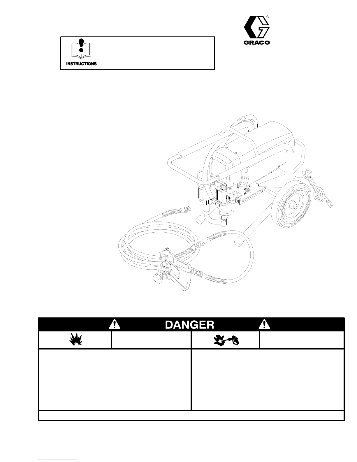
ULTRA) 600 Airless Paint Sprayer
2750
psi (195 bar) MAXIMUM WORKING PRESSURE
Model 231–307, Series A
Complete
T
ip Guard and SwitchT
Model 231–325, Series A
Basic
sprayer with hoses, gun, RAC IV DripLess
ip
sprayer only
Rev A
NOTE: This
is an example of the DANGER label on your sprayer
bel is available in other languages, free of charge. See page 39 to order
FIRE
EXPLOSION HAZARD
Spray
painting,
uids
in confined areas can result in fire or explosion.
Use
outdoors or in extremely well ventilated areas. Ground
ment,
hoses, containers and objects being sprayed.
Avoid
all ignition sources such as
cloths,
open flames
rettes,
arcs from connecting or disconnecting power cords or turn
ing
light switches on and off.
Failure
to follow this warning can result in death or serious injury
flushing or cleaning equipment with flammable liq
such as pilot lights, hot objects such as ciga
static electricity from plastic drop
READ
AND UNDERST
GRACO INC. P.O. BOX 1441
. This la
-
.
AND
Liquids
-
equip
-
-
-
.
AND ALL LABELS AND INSTRUCTION MANUALS BEFORE USE
can be injected into the body by high pressure airless spray
or
leaks – especially hose leaks.
Keep
body clear of the nozzle. Never stop leaks with any part of the
body.
Drain all pressure before removing parts. A
gering
of gun by always setting safety latch when not spraying.
Never spray without a tip guard.
In case of accidental skin injection, seek immediate
“Surgical
Failure to follow this warning can result in amputation or serious
injury.
T
reatment”.
MINNEAPOLIS, MN
COPYRIGHT
1994, GRACO INC.
SKIN INJECTION
HAZARD
55440–1441
02982
void accidental trig
-
Page 2

Table
of Contents
Warnings 3.
Setup 9
Startup 12
Shutdown
Flushing 15
Troubleshooting 17
General
Motor Test 22.
Motor
Displacement
Motor 28
Motor
Power
. . . . . . . . . . . . . . . . . . . . . . . . . . . . . . . . . . . . .
. . . . . . . . . . . . . . . . . . . . . . . . . . . . . . . . . . . . . . . . .
. . . . . . . . . . . . . . . . . . . . . . . . . . . . . . . . . . . . . . .
and Care
. . . . . . . . . . . . . . . . . . . . . . . . . . . . . . . . . . . . .
Repair Information
. . . . . . . . . . . . . . . . . . . . . . . . . . . . . . . . . . .
Brush
. . . . . . . . . . . . . . . . . . . . . . . . . . . . . . . . . . . . . . . .
Control Board
Supply Cord
. . . . . . . . . . . . . . . . . . . . . . . . . . . . . . . . .
Pump
. . . . . . . . . . . . . . . . . . . . . . . . . .
. . . . . . . . . . . . . . . . . . . . . . . . . . . . . . .
. . . . . . . . . . . . . . . . . . . .
. . . . . . . . . . . . . . . . . . . . . . . . . .
. . . . . . . . . . . . . . . . . . . . . . . . . .
. . . . . . . . . . . . . . . . . . . . . . . . . . .
14.
21.
23.
24.
29.
29.
On/Off
Switch
Drive
Housing, Connecting Rod, Crankshaft
Pressure Transducer 32.
Pressure T
Suction
Drain Valve 35.
Complete
Displacement
Dimensions 39
Accessories 39
Graco
Phone
Hose
Ultra)Warranty
Numbers
. . . . . . . . . . . . . . . . . . . . . . . . . . . . . . . .
. . . . .
. . . . . . . . . . . . . . . . . . . . . . . . .
ransducer Seal
. . . . . . . . . . . . . . . . . . . . . . . . . . . . . . . .
. . . . . . . . . . . . . . . . . . . . . . . . . . . . . . . . . .
Sprayer Parts
Pump Parts
. . . . . . . . . . . . . . . . . . . . . . . . . . . . . . . . . . .
. . . . . . . . . . . . . . . . . . . . . . . . . . . . . . . . . .
. . . . . . . . . . . . . . . . . . . . . . . . . . . . . .
. . . . . . . . . . . . . . . . . . . . .
. . . . . . . . . . . . . . . . . . . . . . .
. . . . . . . . . . . . . . . . . . . . .
and Disclaimers
. . . . . . . . .
29.
30.
33.
34.
36.
38.
40.
40.
Page 3
High
Observe All W
WARNINGS
Pressure Spray Can Cause Serious Injury
arnings. Read and understand all instruction manuals before operating equipment.
FIRE OR EXPLOSION HAZARD
. For Professional Use Only.
General
This
from the gun, leaks or ruptured components can inject fluid
through your skin and into your body and cause extremely
serious bodily injury
fluid injected or splashed into the eyes or on the skin can
cause serious damage.
NEVER point the spray gun at anyone or at any part of the
body
try to “blow back” paint; this is NOT an air spray system.
ALWA
spraying.
ALWA
fore cleaning or removing the spray tip or servicing any sys
tem equipment.
NEVER try to stop or deflect leaks with your hand or body
Be sure equipment safety devices are operating properly
before each use.
Medical
If
any fluid appears to penetrate your skin, get
MEDICAL CARE AT ONCE. DO NOT TREAT AS A SIMPLE
CUT
Spray
Be
each use. Do not remove or modify any part of the gun; this
can cause a malfunction and result in serious bodily injury
Safety
equipment generates very high fluid pressure. Spray
, including the need for amputation. Also,
. NEVER put hand or fingers over the spray tip. NEVER
YS have the tip guard in place on the spray gun when
YS follow the
Alert––Airless Spray W
. T
ell the doctor exactly what fluid was injected.
Note to Physician
jury
. It is important to treat the injury surgically as soon as
possible.
T
oxicity is a concern with some exotic coatings injected
directly into the blood stream. Consultation with a plastic
surgeon or reconstructive hand surgeon may be advisable
Do not delay treatment to research toxicity
Pressure Relief Procedure
, below
ounds
EMERGENCY
:
Injection in the skin is a traumatic in
, be
-
-
.
-
.
Gun Safety Devices
sure all gun safety devices are operating properly before
.
Safety Latch
Whenever
the gun safety latch in the closed or “safe” position, making
the gun inoperative. Failure to set the safety latch can result
in accidental triggering of the gun.
you stop spraying, even for a moment, always set
Diffuser
The gun dif
injection
regularly.
then remove the spray tip. Aim the gun into a metal pail, hold
ing the gun firmly to the pail. Using the lowest possible pres
sure, trigger the gun. If the fluid emitted
irregular stream, replace the dif
fuser breaks up spray and reduces the risk of fluid
when the tip is not installed. Check dif
Follow the
Pressure Relief Procedure
is not
fuser immediately
Tip Guard
ALWAYS
spraying. The tip guard alerts you to the fluid injection hazard
and helps reduce, but does not prevent, the risk of acciden
tally placing your fingers or any part of your body close to the
spray tip.
have the tip guard in place on the spray gun while
Trigger Guard
Always
have the trigger guard in place on the gun when
spraying to reduce the risk of accidentally triggering the gun if
it is dropped or bumped.
Spray T
Use
the spray tip clogs while spraying, engage the gun safety
.
latch immediately
cedure
NEVER wipe of
is fully relieved and the gun safety latch is engaged.
ip Safety
extreme caution when cleaning or changing spray tips. If
and then remove the spray tip to clean it.
. ALWAYS follow the
f build–up around the spray tip until pressure
Pressure Relief Pro
fuser operation
, below
,
dif
fused into an
.
-
-
-
-
Pressure
To
reduce the risk of serious bodily injury
injection, splashing fluid or solvent in the eyes or on the
skin, or injury from moving parts or electric shock, always
follow this procedure whenever you shut of
when checking or servicing any part of the spray system,
when installing, cleaning or changing spray tips, and when
ever you stop spraying.
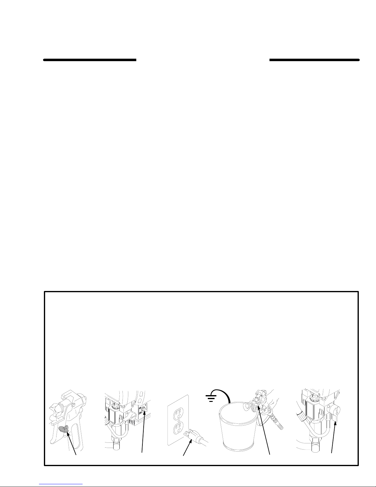
1.
Engage the gun safety latch.
2. Turn the ON/OFF switch to OFF.
3.
Unplug the power supply cord.
Relief Procedure
1,5
, including fluid
f the sprayer
2
4.
Disengage the gun safety latch. Hold a metal part of the
gun firmly to the side of a grounded metal pail, and trig
ger the gun to relieve pressure.
5.
,
-
34
Engage the gun safety latch.
6.
Open the pressure drain valve, having a container ready
to catch the drainage. Leave the valve open until you
are ready to spray again.
If you suspect that the spray tip or hose is completely
clogged, or that pressure has not been fully relieved after
following the steps above,
guard retaining nut or hose end coupling to relieve pres
sure gradually
hose.
, then loosen completely
VERY SLOWL
. Now clear the tip or
Y loosen the tip
6
-
-
02983
Page 4

MOVING PARTS HAZARD
Moving
parts can pinch or amputate your fingers or other
body parts. KEEP CLEAR of moving parts when starting or
operating the sprayer
dure
on page 3 before checking or servicing any part of the
sprayer
, to prevent it from starting accidentally
. Follow the
Pressure Relief Proce
.
-
EQUIPMENT MISUSE HAZARD
General
Any
overpressurizing, modifying parts, using incompatible chemi
cals and fluids, or using worn or damaged parts, can cause
them to rupture and result in fluid injection, splashing in the
eyes or on the skin, or other serious bodily injury
plosion or property damage.
NEVER alter or modify any part of this equipment; doing so
could cause it to malfunction.
CHECK all spray equipment regularly and repair or replace
worn or damaged parts immediately
Always wear protective eyewear
rator as recommended by the fluid and solvent manufacturer
System
This
working pressure
cessories used are rated to withstand this pressure. DO NOT
exceed the maximum working pressure of any component or
accessory used in the system.
Fluid and Solvent Compatibility
BE
compatible with the wetted parts shown in the
DATA
facturer’
Do
halogenated hydrocarbon solvents or fluids containing such
solvents in this equipment, which contains aluminum and/or
zinc parts. Such use could result in a serious chemical reac
tion, with the possibility of explosion, which could cause death,
serious bodily injury and/or substantial property damage.
Safety
misuse of the spray equipment or accessories, such as
, or fire, ex
.
, gloves, clothing and respi
Pressure
sprayer can develop
SURE that all fluids and solvents used are chemically
on page 39. Always read the fluid and solvent manu
s literature before using them in this sprayer
not use 1,1,1-trichloroethane, methylene chloride, other
.
Be sure that all spray equipment and ac
195 bar (2750 psi)
maximum
TECHNICAL
.
-
-
.
-
-
-
HOSE SAFETY
High
pressure fluid in the hoses can
hose develops a leak, split or rupture due to any kind of wear
damage or misuse, the high pressure spray emitted from it
can cause a fluid injection injury or other serious bodily injury
or property damage.
All fluid hoses must have spring guards on both ends!
Spring guards help protect the hose from kinks or bends at or
close to the coupling which can result in hose rupture.
TIGHTEN all fluid connections securely before each use.
High pressure fluid can dislodge a loose coupling or allow
high pressure spray to be emitted from the coupling.
NEVER
entire hose for cuts, leaks, abrasion, bulging cover
or movement of the hose couplings. If any of these conditions
exist, replace the hose immediately
high pressure hose or mend it with tape or any other device. A
repaired hose cannot contain the high pressure fluid.
Handle
move equipment. Keep hoses clear of moving parts and hot
surfaces of the pump and gas engine. Do not use fluids or
solvents which are not compatible with the inner tube and
cover of the hose. DO NOT expose Graco hose to tempera
tures above 180 F (82C) or below –40 F (–40
use a damaged hose. Before each use, check the
and route hoses carefully
Hose Grounding Continuity
Proper
hose grounding continuity is essential to maintaining a
grounded spray system. Check the electrical resistance of
your fluid hoses at least once a week. If your hose does not
have a tag on it which specifies the maximum electrical resis
tance,
contact the hose supplier or manufacturer
mum
resistance limits. Use a resistance meter in the appro
priate range for your hose to check the resistance. If the
resistance exceeds the recommended limits, replace it imme
diately
. An ungrounded or poorly grounded hose can make
your system hazardous. Also read FIRE OR EXPLOSION
HAZARD.
be very dangerous. If the
, or damage
. DO NOT try to recouple
. Do not pull on hoses to
-
C).
for the maxi
-
,
-
-
-
FIRE OR EXPLOSION HAZARD
Static
electricity is created by the flow of fluid through the
pump and hose. If every part of the spray equipment is not
properly grounded, sparking may occur
become hazardous. Sparking may also occur when plugging
in or unplugging a power supply cord. Sparks can ignite
fumes from solvents and the fluid being sprayed, dust parti
cles and other flammable substances, whether you are
spraying indoors or outdoors, and can cause a fire or explo
sion and serious bodily injury and property damage. Plug the
sprayer into a grounded outlet at least 20 ft. (6 m)
sprayer.
If
you experience any static sparking or even a slight shock
while using this equipment,
Check the entire system for proper grounding. Do not use the
system again until the problem has been identified and cor
rected.
stop spraying immediately
, and the system may
-
-
from the
.
-
Grounding
To
reduce the risk of static sparking, ground the sprayer and
all other spray equipment used or located in the spray area.
CHECK your local electrical code for detailed grounding in
structions for your area and type of equipment. BE SURE to
ground all of this spray equipment:
1.
Sprayer:
an adapter
be rated for at least 15
plug into a properly grounded outlet. Do not use
. Extension cords must have three wires and
amps.
-
2.
Fluid hoses:
500 ft (150 m) combined hose length to ensure grounding
continuity
3.
Spray gun:
properly grounded fluid hose and sprayer
Object being sprayed:
4.
5.
Fluid supply container:
6.
All solvent pails used when flushing,
code. Use only metal pails, which are conductive. Do not
place the pail on a non–conductive surface, such as pa
per or cardboard, which interrupts the grounding continu
ity.
T
o maintain grounding continuity when flushing or reliev
7.
ing pressure
the side of a grounded metal pail, then trigger the gun.
Flushing
Reduce
splashing by following the flushing procedure given on page
15 of this manual. Follow the
page 3, and remove the spray tip before flushing. Hold a
metal part of the gun firmly to the side of a grounded metal pail
and use the lowest possible fluid pressure during flushing.
the risk of fluid injection injury
use only grounded hoses with a maximum of
. See
Hose Grounding Continuity.
obtain grounding through connection to a
according to local code.
according to local code.
, always hold a metal part of the gun firmly to
Safety
Pressure Relief Procedure
IMPORTANT
United
States Government safety standards have been adopted under the Occupational Safety and Health Act. These standards
– particularly the General Standards, Part 1910, and the Construction Standards, Part 1926 – should be consulted.
4 308-319
.
according to local
-
-
-
, static sparking, or
on
Page 5
Avertissement
La
pulvérisation à haute pression peut causer des blessures très graves.
Réservé exclusivement à l’usage professionnel. Observer toutes les consignes de sécurité.
Bien lire et bien comprendre tous les manuels d’instructions avant d’utiliser le matériel.
RISQUES D’INJECTION
Consignes
Cet appareil produit un fluide à très haute pression. Le fluide
pulvérisé
fuites
ou de ruptures peut pénétrer sous la peau ou à l’interieur
du
corps et entrainer des blessures très graves, voir même une
amputation.
sant ou entrant dans les yeux peut aussi entrainer des blessures graves.
NE
JAMAIS pointer le pistolet vers quelqu’un ou
quelconque
sur
l’ajutage du pulvérisateur
la peinture. Cet appareil N’est P AS un compresseur
pneumatique.
TOUJOURS
tolet
pendant la pulvérisation.
TOUJOURS observer la March à Suivre pour Détendre la
Pression donnée plus loin, avant de nettoyer ou d’enlever
l’ajutage
sur
une partie de l’appareil.
NE JAMAIS essayer d’arrêter ou de dévier les fuites avec la
main
ou le corps.
Avant chaque utilisation, bien s’assurer que les dispositifs de
sécurité
Soins
En
cas de pénétration de fluide sous la peau:
MEDIATEMENT DES SOINS MEDICAUX D’URGENCE. Ne
pas
soigner cette blessure comme une simple coupure.
A
vis au medecin: La pénétration des fluides sous la peau est
un traumatisme.
ment cette blessure immédiatement.
traitement pour effectuer des recherches sur la toxicité.
Certains revêtements exotiques sont dangereusement
toxiques quand ils sont injectés directement dans le sang.
Il est souhaitable de consulter un chirurgien esthétique ou
un chirurgien spécialisé dans la
generales de sécurité
par le pistolet ou le fluide sous pression provenant de
Même sans être sous pression, le fluide
du corps. NE
garder la protection
du pulvérisateur, ou d’ef
fonctionnent correctement.
JAMAIS mettre la main ou les doigts
. NE JAMAIS essayer de “refouler”
de l’ajutage en place sur le pis
fectuer un travail quelconque
éclabous
vers une partie
medicaux
DEMANDER
Il est important de traiter chirurgicale
reconstruction des mains.
Ne pas retarder le
IM
Dispositifs de sécurité du pistolet
Avant
chaque utilisation, bien s’assure que
de sécurité du pistolet fonctionnent correctement. Ne pas enlever ni modifier une partie quelconque du pistolet; ceci
risquerait d’entraîner un mauvais fonctionnement et des blessures graves.
-
V
errou de sécurité
A chaque fois que l’on s’arrête de pulvérisér , même s’il s’agit
d’un
court instant, toujours mettre le verrou de sécurité du pis
tolet sur la position “fermée” ou “sécurité” (“safe”) pour
empêcher le pistolet de fonctionner . Si le verrou de sécurité
n’est
pas
mis, le pistolet peut se déclencher accidentellement.
Diffuser
Le
dif
fuseur du pistolet sert à diviser le jet et à réduire les risques
d’injection accidentelle quand l’ajutage n’est pas en place.
Vérifier le fonctionnement du dif fuseur régulièrement. Pour
cette
vérification, détendre la pression en observant la Marche
à
Suivre
lever
en
utilisant la pression la plus faible possible, appuyer sur la
gachette du pistolet. Si le fluide projete
forme
pour Détendre la Pression
l’ajutage du pulvérisateur
métal, en le maintenant fermement contre le seau. Puis,
de jet irrégulier
, remplacer immédiatement le dif
. Pointer le pistolet dans un seau
Protection de l’ajutage
TOUJOURS
pistolet
de
l’ajutage attire l’attention sur les risques d’injection et contri
bue
à réduire, mais n’évite pas le risque, que les doigts ou une
partie
ximité
Consignes de sécurité concernant l’ajutage du
pulvérisateur
Faire extremement attention à l’occasion du nettoyage ou du
remplacement des ajutages du pulvérisateur . Si l’ajutage se
bouche
-
rou de sécurité du pistolet. T OUJOURS bien observer la
Marche à Suivre pour Détendre la Pression puis enlever
l’ajutage
JAMAIS essuyer
NE
du pulvérisateur avant que la pression ne soit completement
tombée
maintenir la protection de l’ajutage en place sur le
du pulvérisateur pendant la
quelconque du corps
immédiate de l’ajutage du pulvérisateur
pendant la pulvérisation, mettre immédiatement le ver
du pulvérisateur pour le nettoyer
et que le verrou
ne passent accidentellement à pro
ce qui s’est accumulé autour de l’ajutage
de sécurité du pistolet ne soit engagé.
pulvérisation. La protection
tous les dispositifs
donnée plus loin puis en
n’est pas
.
-
-
en
diffusé sous
fuseur.
-
-
.
-
Marche
Pour réduire les risques de blessures graves, y compris les
blessures par projection de fluide ou celles causées par de
éclaboussures
en
chaque
vérification,
changement
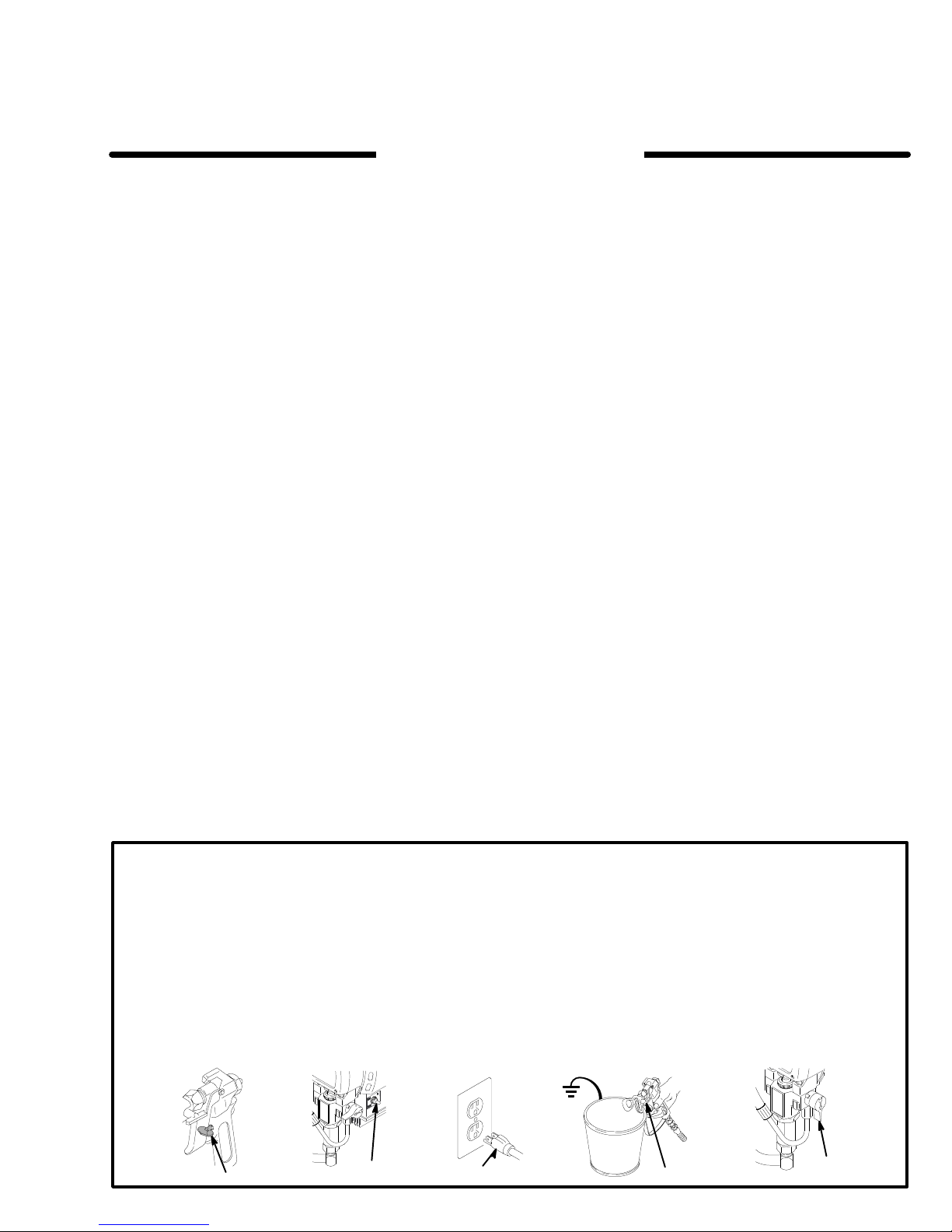
1.
2.
3.
à Suivre pour Détendre la Pression
dans les yeux ou sur la peau, par des pièces
mouvement, toujours bien observe cette marche à suivre
fois que l’on arrête le pulvérisateur
du égale ou du nettoyage du système ou lors du
des ajutages.
Engager le verrou de sécurité du pistolet.
Mettre le levier d’arrêt du moteur sur ARRET (OFF).
Débrancher le cord d’alimentation.
1,5
, à
l’occasion de la
2
4.
Désengager le verrou de sécurité du pistolet. T
maintenant une partie métallique du pistolet fermement
appuyé contre le côte d’un seau en métal, actionner le
pistolet pour libérer la pression.
5.
Engager le verrou de sécurité du pistolet.
6.
Ouvrir la soupape de sécurité et la laisser ouverte jus
qu’à ce que l’on soit prêt à se servir de nouveau du pul
vérisateur.
Si
l’on soupconne que le tuyau ou l’ajutage est complètement
bouché
ou que la pression n’a pas
après avoir procédé aux opérations ci–dessus, desserrer
TRES LENTEMENT un raccord de bout de tuyau ou l’écrou
de
retenue de la protection de l’ajutage et libérer progressive
ment
la pression.
3
4
été complètement libérée
out en
6
-
-
-
02983
308-319 5
Page 6

RISQUES EN CAS DE MAUVAISE UTILISATION DU MATERIAL
Consignes
Toute utilisation anormale de l’appareil de pulvérisation ou des
accessoires comme, par exemple, la mise sous une pression
excessive, les modifications de pièces, l’utilisation de produits
chimiques
usées ou abîmées peut causer des dégâts à l’appareil ou des
ruptures de pièces et entraîner une injection de liquide ou
d’autrès blessures sérieuses, un incendie, une explosión ou
d’autrès
Ne Jamais alterer ou modifier une piece de cet appareil; ceci
risquerait
Vérifier régulièrement tout l’appareil de pulvérisation et ses
equipements et réparer ou remplacer immédiatement les
pièces
générales de sécurité
et d
e m
atière
s i
ncompatible
d
égâts.
d’entraîner son mauvais fonctionnement.
usées ou abîmées.
s e
t l
’utilisatio
n d
e p
ièces
Pression
Ce
pulvérisateur peut
TRAVAIL 195 bar (2750 lb/po2). S’assurer que tous les
éléments
résister à la pression maximum de travail de ce pulvérisateur.
NE
éléments
Compatibilité chimique des corps
Bien s’assurer que tous les corps des solvants utilisés sont
chimiquement compatibles avec les parties mouillées indiquées
neusement
et
du pulvérisateur et ses accessoires sont conçus pour
P
AS depasser la pression maximum de travail d’aucun des
ou accessoires utilisés avec cet appareil.
dans les
solvants utilisés avant de s’en servir dans ce pulvérisateur
les documents et brochures du fabricant des fluides
produire une PRESSION MAXIMUM DE
Technical
Data
, à page 39. T
oujours lire soig
-
.
MESURES
Le fluide à haute pression circulant dans les tuyaux peut être
très
dangereux. En cas de fuite sur le tuyau, de fissure, déchi
rure ou rupture à la suite de l’usure, de dégâts ou d’une
mauvaise
en proviennent peuvent entraîner des blessures graves par
pénétration
matériels.
Tous
de
ent
les
du
Serrer
fluide sous pression peut faire sauter un raccord desserre ou
produire
Ne Jamais utiliser un tuyau endommagé. Ne Pas essayer de
refaire le raccord d’un tuyau haute pression ni de réparer le
tuyau
réparé
utilisation, les projections de fluide haute pression qui
sous la peau ou par contact, ainsi que des dégâts
les tuyaux flexibles doivent avoir des ressorts
protection aux bouts!
à eviter la formation de pliures, de boucles ou de nœuds sur
tuyaux qui pourraient
raccord ou à son voisinagé.
fermement tous les raccords avant chaque utilisation. Le
un jet à haute pression s’échappant par le raccord.
avec du ruban adhesif
ne peut pas résister au fluide sous pression.
DE
SECURITE CONCERNANT LES TUY
Les spirales de protection contribu
entraîner la rupture du tuyau à l’endroit
ou par tout autre moyen. Un tuyau
RISQUES D’INCENDIE OU D’EXPLOSION
De
l’électricité statique est produite par le passage du fluide à
grande
vitesse dans la pompe et dans les tuyaux. Si toutes les
pièces de l’appareil de pulvérisation ne sont pas convenablement
reliés à la masse ou
produire et l’appareil risque d’être dangereux. Des étincelles
peuvent également se produire à l’occasion du branchement
ou
du débranchement du cordón d’alimentation. Les
sont
suf
fisantes pour allumer les vapeurs de solvants et le fluide
pulvérisé,
substances inflammables, et
ou
matériels. Toujours brancher le
trouvant
où
S’il
sentez la moindre
risation
vous
et
corrigé.
Mise à la terre ou à la masse
Pour
statique,
trouvant dans la zone de pulvérisation doivent être reliés à la
terre
mise
CONSULTER le code ou les réglementations électriques locales.
suivants
1.
les fines particules de poussieère ainsi que d’autrès
une
explosión, ainsi que des blessures graves et des dégâts
à au moins 6 m (20 pieds) de l’appareil et de l’endroit
se fait la pulvérisation.
se produit des étincelles d’électricité statique, ou si vous res
. Vérifiez que le système entier est bien mis à laterre. Ne
servez pas du système avant que le problème soit identifié
réduire les risques de production d’étincelles d’électricité
le pulvérisateur et tous les équipements utilisés ou se
ou à la masse.
à la terre dans la region et le type particulier d’équipement,
S’ASSURER que tous les équipements de
sont bien reliés à la terre:
Pulvérisateur:
longe qui doivent être équipés d’une prise à 3 fiches en
bon état, dans une prise de courant convenablement mise
à la terre. Ne pas utiliser d’adaptateur
doivent avoir 3 fils et être prevues pour 15 ampères.
décharge,
Brancher le cordón d’alimentation ou la ral
6 308-319
à la terre, des étincelles peuvent se
elles peuvent causer un incendie
pulvérisateur dans une prise se
arrêtez immédiatement la pulvé
Pour connaître le detail des instructions de
. T
outes les rallonges
spirale
étincelles
pulvérisation
-
AUX FLEXIBLES
Manipuler
-
leur
pas utiliser de fluides ou de solvants qui ne sont pas compatibles
PAS
(180
Continuité de la mise à la terre des tuyaux
Une
-
tielle
tion.
à
air
pas d’étiquette qui précise la résistance électrique maximum,
prenez contact avec le fournisseur de tuyaux ou la fabricant
pour
de
fiez la résistance. Si celle–ci dépasse les límites recommandées, remplacez le tuyau immédiatement. Un tuyau sans
mise
traîner des risques pour votre systeme. Lisez aussi LES
RISQUES D’INCENDIE OU D’EXPLOSIÓN ci–dessus.
2.
3.
4.
5.
6.
-
-
7.
Mesures de sécurité concernant le rincage
Pour réduire les risques de blessures par pénétration de la
peau et les risques dûs aux etincelles d’electricite statique ou
aux
donnée à la page 15 de ce manuel. Observer la “Marche à
Suivre pour Détendre la Pression” donnée à la 5 en
l’ajutage
métallique du pistolet fermement appuyée contre le côté d’un
seau
dant
les tuyaux avec precaution
chemin. Ne pas déplacer le fluide en tirant sur le tuyau. Ne
avec l’enveloppe intérieure ou extérieure du tuyau.
exposer le tuyau à
F)
ou inférieures à –40C (–40
bonne continuité de la mise à la terre des tuyaux est
pour maintenir la mise à la terre de l’ensemble de vaporisa
Vérifiez la résistance électrique de vos tuyaux à fluides et
, au moins une fois par semaine. Si votre tuyau ne comporte
avoir les límites de résistance maximum. Utilisez un mètre
résistance de la gamme appropriée pour votre tuyau et véri
à la terre ou avec une mise à la terre incorrecte peut en
Tuyaux
flexibles:
terre,
n’utiliser que des tuyaux comportant une mise à la
terre et ayant une longueur maximum combinée de 150 m
(1500 pieds). Se reporter également au paragraphe
nuité du circuit de mise à la terre des tuyaux.
Pistolet
: Réaliser la mise à la terre en le raccordant à un
tuyau flexible et à un pulvérisateur dèjá convenablement
reliés à la terre.
Récipient d’alimentation:
mentations locales.
des températures supérieures à 82
Afin d’assurer la continuité
observer le code ou les régle
et choisir soigneusement
F).
Objets, matériel ou surfaces reçevant la pulvérisation:
server le code ou les réglementations locales.
Tous les seaux de solvants
server le code ou les réglementations locales. N’utiliser
que des saux métalliques conducteurs de l’électricité. Ne
pas mettre le seau sur une surface non conductrice
comme sur du papier ou du carton car cela interromprait la
continuité de la mise à la terre.
utilisés pour le rinçage: ob
Pour conserver la continuité de la mise à la terre quand on
rince le matériel ou quand on libére la pression
maintenir une partie métallique du pistolet fermement ap
puyée contre le côté d’un seau en métal puis appuyer sur
la détente du pistolet.
éclaboussures, observer la marche à suivre
du pulvérisateur avant le rincage
en métal et utiliser la pression la plus
le rincage.
. Maintenir une partie
faible possible pen
NE
C
essen
de la mise à la
Conti-
-
ob
-
-
, toujours
pour le rincage
-
enlever
-
-
-
-
-
Page 7
ADVERTENCIA
El
rociado a alta presión puede causar graves lesiones. Solo para uso profesional. Respete los avisos de
advertencia. Lea y entienda todo el manual de instrucciónes antes de manejar el equipo.
PELIGRO DE INYECCION DE FLUIDO
Seguridad
Este
equipo genera un fluido a una presión muy alta. El rociado
de la pistola, los escapes de fluido o roturas de los componentes
lesiones extremadamente graves, incluyendo a veces la
necesidad de amputación. También, el fluido inyectado o salpicado
NUNCA apuntar la pistola hacia alguien o alguna parte del
cuerpo.
quilla.
un
sistema de rociado de aire.
SIEMPRE tener colocado el protector de la boquilla en la pistolamientras
SIEMPRE seguir el procedimiento de descarga de presión,
dado
vicioa
NUNCA
cuerpo.
Asegurar
funciónando
Tratamiento
Si pareciera que un poco de fluido penetró la piel, conseguir
TRATAMIENTO MÉDICO DE URGENCIA DE INMEDIA TO.
NO
TRATAR LA HERIDA COMO UN SIMPLE CORTE.
al
médico exactamente cua fluido fue.
Aviso
causa
camente la lesión a la brevedad posible. No demorar el
tratamiento
de
suma importancia en algunas pinturas exóticas cuando se
inyectan directamente al torrente sanguineo. Sirá conveniente consultar a un especialista en cirugia plástica o
reconstructiva
general
pueden inyectar fluido en la piel y el cuerpo y causar
en los ojos puede causar graves daños.
NUNCA colocar la mano o los
NUNCA
másabjo, antes de
cualiquier equipo del sistema.
tratar de “hacer retornar la pintura”; este NO es
se está pulverizando.
limpiar o sacar la boquilla o de dar ser
tratar de parar o desviar los escapes
que todos los aparatos de seguridad del equipo están
bien antes de cada uso.
dedos encima de la bo–
con la mano o el
médico
al médico:
una lesión traumática.
Si se llega a inyectar este fluido en la piel se
para investigar la toxicidad. La toxicidad es algo
de las manos.
Es importante tratar
quirúrgi
Decir
Aparatos
Asegurar
funciónando bien antes de cada uso. No sacar ni modificar
ningúna
miento
Pestillo
Cada
momento, siempre colocar el pestillo de seguridad en la posición “cerrada” lo que deja la pistola inoperante. El no hacerlo
puede
de seguridad de la pistola pulverizadora
que todos los aparatos protectores de la pistola están
pieza de la pistola pues podria causar el malfuncióna
de
la misma con las consiguientes lesiones personales.
de seguridad
vez que se deje de pulverizar
llevar al disparo imprevisto de la pistola.
, aunque sea por un breve
Difusor
El
difusor de la pistola dispersa el chorro pulverizado y reduce
el riesgo de inyección cuando no está instalada la boquilla.
Revisar
procedimiento de descarga de presión, dado más abajo, y
-
después
co,
bajo
perso
Protector
SIEMPRE
mientras
contra
la
cuerpo
Seguridad
Tener
ra a obstruirse mientras está pulverizando,
tillo de la pistola de inmediato. SIEMPRE seguir el procedi-
miento de descarga de presión y después sacar la boquilla
para
NUNCA
quilla
y
con regularidad el
sacar la boquilla. Apuntar la pistola a un balde metáli
sosteniéndola bien firme contra el. Utilizando la presión más
posible, disparar la pistola. Si el fluido emitido no sale dis
en un
chorro irregular
funciónamiento del difusor
, reemplazar de inmediato el difusor
de la boquilla
tener
el protector de la boquilla colocado en la pistola
se está pulverizando.
el peligro de inyección
colocación accidental de los dedos o cualquier otra parte del
cerca de la boquilla.
Este protector llama la atención
y ayuda a reducir
de la boquilla pulverizadora
mucho cuidado al limpiar o cambiar las
limpiarla.
limpiar la acumulación de pintura alrededor de la bo–
antes de que se haya descargado por completo la presión
el pestillo este enganchado.
boquillas. Si llega
enganchar el pes
-
. Seguir el
-
.
, pero no evita,
-
-
Procedimiento
Para
reducir el riesgo de
cluyendo inyección o lesiones causadas por piezás en
movimiento o choque eléctrico, siempre seguir este
procedimiento
o
dar servicio a cualquier
al
instalar
deja
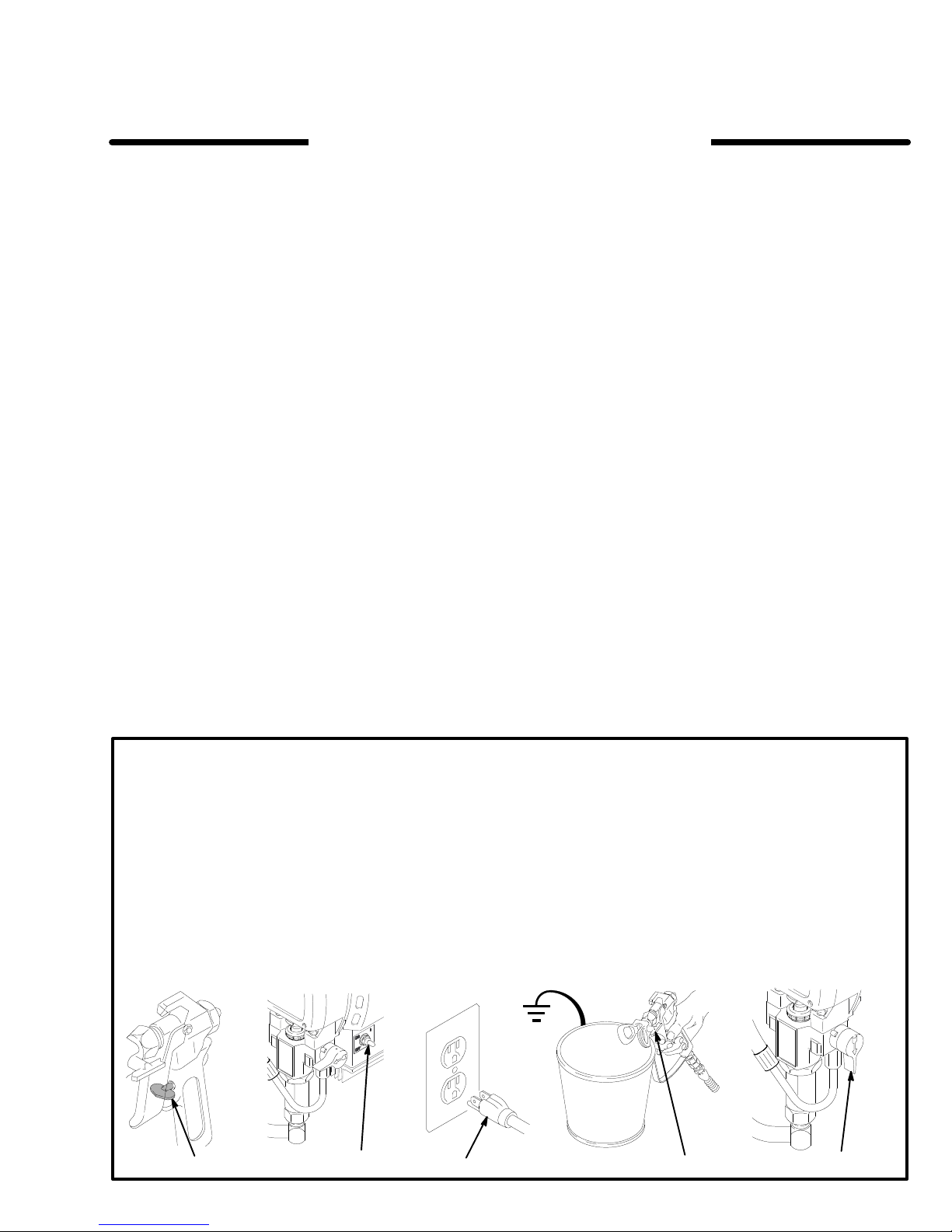
1.
2.
3.
, limpiar o cambiar las boquillas, y cada vez que se
de pulverizar
Enganchar el pestillo de la pistola.
Mover el interruptor eléctrico (ON/OFF) a la posición
OFF (apagado).
Desenchufar el cordón electrico.
de descarga de presión
sufrir graves lesiones corporales, in
al apagar la máquina pulverizadora, al revisar
parte del sistema de pulverización,
.
1,5
4.
Desenganchar el pestillo de la pistola. Sujetar una parte
-
2
34
metálica de la pistola bien firme contra un balde de
metal, y disparar la pistola para descargar la presión.
5.
Enganchar el pestillo de la pistola.
6.
Abrir la válvula de presión. Dejar la válvula de alivio de
presión abierta hasta que se este nuevamente listo para
pulverizar.
Si se sospecha que la boquilla o la manguera está completamente obstruida, o que no se ha descargado por completo
la
presión después de haber seguido el procedimiento
anterior, aflojar muy lentamente la tuerca de retención del
protector
guera y descargar gradualmente la presión, después,
aflojarlo
guera.
de la boquilla o acoplamiento de la punta de la man
por completo. Luego, despejar la boquilla o la man
6
02983
-
-
308-319 7
Page 8

PELIGRO POR MAL USO DEL EQUIPO
Seguridad
Cualquier
como sobre presurización, modificación de piezás, uso de
matériales
piezás dañadas o desgastadas, puede hacen que se rompan
y causen la inyección de fluido u otras lesiones corporales
graves,
NUNCA alterar o modificar ningúna pieza de este equipo; el
hacerlo
REVISAR con regularidad el equipo pulverizador y reparar o
reemplazar
general
mal uso del equipo pulverizador o los accesorios, tal
y productos quimicos incompatibles, o utilización
incendio, explosión o dañon a la propiedad.
podria causar una avería.
de inmediato las piezás dañadas o desgastadas.
de
SEGURIDAD EN EL USO DE LAS MANGUERAS
El fluido que escapa a alta presión por las mangueras puede
ser
muy peligroso. Si en la manguera se desarrolla un
una
rotura o rajadura debido a cualquier tipo de desgaste, daño
o maltrato, el chorro a alta presión emitido por alli puede causar
una lesion por inyección u otras lesiones corporales graves o
daños
a la propiedad.
!Todas las mangueras para fluidos tienen que tener
guardas
mangueras
tos
manguera.
Antes
El fluido a alta presión puede desalojar un acoplamiento suelto
o
dejar que por el escape un chorro a alta presión.
NUNCA usar una manguera que está dañada. Siempre,
revisarla
abultada, o acoplamientos sueltos o dañados. Si llegara a en
contrarse cualquiera de estás condiciónes, reemplazar de inmediato la manguera. NO intentar racoplar una manguera de
alta presión o enmendarla con cinta adhesiva u otro matérial
similar. Una manguera que ha sido remendada no aguante el
fluido
de resorte en ambos extremos!
o cerca de ellos, los que podrian traducirse en roturas de la
contra dobleces o retorceduras en los acoplamien
de usarlas, APRET
en busca de cortaduras, escapes, abrasion, cubierta
a alta presión.
AR bien firmes
Estas protegen las
todas las conexiones.
escape,
-
-
Presión
está
presión DE TRABAJO MÁXIMA.
pulverizador
tar la presión máxima de trabajo de está pulverizadora. NO ex
ceder la presión máxima de trabajo de ningún componente o
accesorio
del sistema
pulverizadora puede desarrollar
y sus accesorios
de este sistema.
Asegurar que todo el equipo
tienen la capacidad para aguan
195 barías (2750 psi) de
Compatibilidad de fluido
Siempre leer las instrucciónes del fabricante del fluido y solvente
antes de usarlos en está
na
39.
Siempre usar gafas, guantes, vestimetas protectora y un
respiradero,
del solvente.
MANEJAR Y PASAR CUIDADOSAMENTE LAS MANGUERAS.
usar fluidos o solventes que sean incompatibles con el tubo in
terno
a temperaturas sobre 82 C (180 F) o bajo –40 C (–40
F).
Continuidad
tal como recomiendan los fabricantes del fluido
No tirar de las mangueras para mover el equipo.
y la cubierta dela manguera. NO exponer las mangueras
del circuito de puestá a tierra de la
pulverizadora, dadas en la pági
y
No
manguera
La continuidad del circuito de puestá a tierra apropiado es
esencial para mantener conectado a tierra el sistema pulverizador. Es indispensable revisar la resistencia eléctrica
máxima
vez
se
el proveedor o fabricante de la manguera para la información
sobre
la
límites
riesgado
a tierra en malas condiciónes. Leer también la información
sobre
de las mangueras de aire y de fluido por lo menos una
a la semana. Si la manguera no tiene una etiqueta
especifica la resistencia eléctrica, ponerse en contacto con
los límites de resistencia. Usar un metro de resistencia en
gama apropiade para comprobar la resistencia; si excede los
recomendados, reemplazarla
tener una manguera sin puestá a tierra o con la puestá
RIESGO DE INCENDIO O EXPLOSION
de inmediato. Es muy ar
en la cual
, más arriba.
-
-
-
-
-
PELIGRO DE INCENDIO O EXPLOSION
El
flujo a alta velocidad del fluido al pasar por la bomba y man
guera
crea electricidad estática. Si todas las partes del
pulverizador no tienen buena tierra, pueden ocurrir chispas,
convirtiendo al sistema en algo peligroso. T ambién, pueden
producirse
co.
y
el chorro de fluido pulverizado, particulas de polvo y otras sus
tancias
causar
y
daños al a propiedad. Enchufar
tomacorriente que se encuentre a por lo menos 6 m (20 pies)
de
la maquina y del area que se va a rociar
Si
ocurre una chispa de electricidad estática o incluso un ligero
choque
de
inmediato
apropiada. No usar de nuevo el sistema hasta haber identificado
Peusta
Para
pulverisadora
se encuentre en el lugar que se va a rociar . CONSULTAR el
codigo
conexiones a tierra exigidas para la zona y tipo de equipo.
ASEGURAR
1.
Pulverizadora:
sor
un tomacorreinte con puesat a tierra aporpiado. No usar
un adaptador
tener très hilos y una capacidad de 15 amperios.
chispas a enchufar o desenchufar
Estás chispas pueden inflamar
in flamables, sea al aire
una explosión o incendio y graves lesiones corporales
electrico mientras se usa el equipo,
. Revisar todo el sistema en busca de una tierra
y soluciónado el problema.
los vapores de los solventes
libre o bajo techo, lo que podria
siempre la pulverizadora a un
el cordón electri
.
dejar de pulverizar
a tierra
reducir el reisgo de chispas estáticas, conectar a tierra la
, cada uno un enchuf de très patas en buen estádo, a
y todo el otro equipo de pulverisar que se use o
electrico de la localidad para las instrucciónes sobre
de conectar a tierra todo
enchufar el cordón electrico, o cable exten
. T
otos los cables extensores tienen que
este equipo pulverisador:
equipo
las
-
2.
Mangueras para fluidos:
puestá a tierra de una longitud combinada de 150 m (500
pies), para asequrar buena continuidad a tierra. Referirse
también al párrafo sobre
-
-
manugeura.
3.
Pistola:
hace la puestá a tierra conectándola a una man
guera de fluido y pulverizadora bien conectadas a tierra.
4.
Suministrar un recipiente:
localidad.
5.
Objeto que se está rociando:
codigo local.
6.
T
odos los baldes de solvente
de conformidad con el código local. Usar
baldes de metal,
balde en una superficie no conductiva, como papel o
cartón, que interumpe la continuidad a tierra.
7.
Para mantenar la continuidad a tierra durante el lavado o
descarga de presión,
de la pistola bien firme contra el costado del
metal,
después apretar el gatillo.
usar solamente mangueras con
continuidad a tierra de la
de acuerdo al código de la
de conformidad con el
usados durante el lavado,
solamente
que sean conductivos. no colocar el
siempre apoyar una parte metálica
Seguridad durante el lavado
Para
reducir el riesgo
piel, o que ocurra una descarga de electricidad estática,
siempre seguir las INSTRUCCIÓNES PARA EL LAVADO,
dadas
-
en la página. 15 Seguir el
de presión en la págna 7, y quita la
de
lavar
.
tra
posible
Apoyar una parte metalica de la pistola bien firme con
el costado de un
de fluido durante el lavado.
de que se inyecte o salpique fluido en la
procedimiento de descarga
boquilla rociadora antes
balde de metal
y usar le presión más
-
balde de
-
baja
Page 9
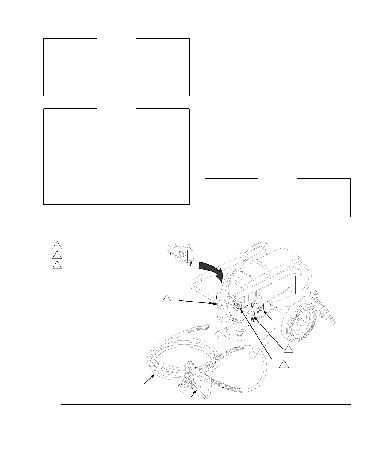
Setup
WARNING
If
you supply your own hoses and spray gun, be
sure the hoses are electrically conductive, that the
gun has a tip guard, and that each part is rated for
at least
2750 psi (195 bar) Working Pressure
. This
is to reduce the risk of serious bodily injury caused
by static sparking, fluid injection or over–pressuri
zation and rupture of the hose or gun.
CAUTION
T
o avoid damaging the pressure control, which may
result in poor equipment performance and compo
nent damage, follow these precautions:
1.
Always use a nylon spray hose at least 50 ft.
(15 m) long.
2.
Never use a wire braid hose as it is too rigid to
act as a pulsation dampener
3.
Never install any shutof
pump and the hose. See Fig. 1.
1. Connect the hose (B) and gun (C)
onto the outlet nipple (A).
and don’t install the spray tip yet!
.
f device between the
and screw it
Don’t use thread sealant,
2. Fill the wet–cup (D).
Pry of
f the wet–cup seal. Fill
the cup 1/3 full with Graco Throat Seal Liquid
(TSL) (68) supplied. Install the seal.
3.
Check the electrical service.
Be sure it is 120 V
,
60 HzAC, 15 Amp (minimum). Use a properly
-
grounded outlet. Do not remove the third (ground
ing) prong of the power supply cord, and do not
use an adapter
Use a 3-wire, (12 ga recommended), 15 amp ex
.
-
tension cord.
-
NOTE:
Long extension cord lengths af
fect sprayer
performance.
4.
Plug in the sprayer. Be sure the ON/OFF switch
(E) is OFF
. Plug the cord into a grounded outlet at
least 20 ft. (6 m) away from the spray area.
WARNING
Proper electrical grounding is essential to reduce
the risk of fire or explosion which can result in seri
ous bodily injury and property damage. Also read
FIRE OR EXPLOSION HAZARD
on page 4.
continued on the next page
-
Fig.1
not install any shutof
Do
Fill 1/3 full with TSL
Shown in closed, or spray position.
f device here.
B
A
E
3
D
C
02984
Page 10

Setup
5. Flush the pump
to remove the oil which was left
in to protect pump parts after factory testing. See
page 15.
6.
Prepare the paint
according to the manufacturer
recommendations. Remove any paint skin. Stir the
paint to mix pigments. Strain the paint through a
fine nylon mesh bag (available at most paint deal
ers) to remove particles that could clog the gun
filter or spray tip. This is an important step toward
trouble–free paint spraying.
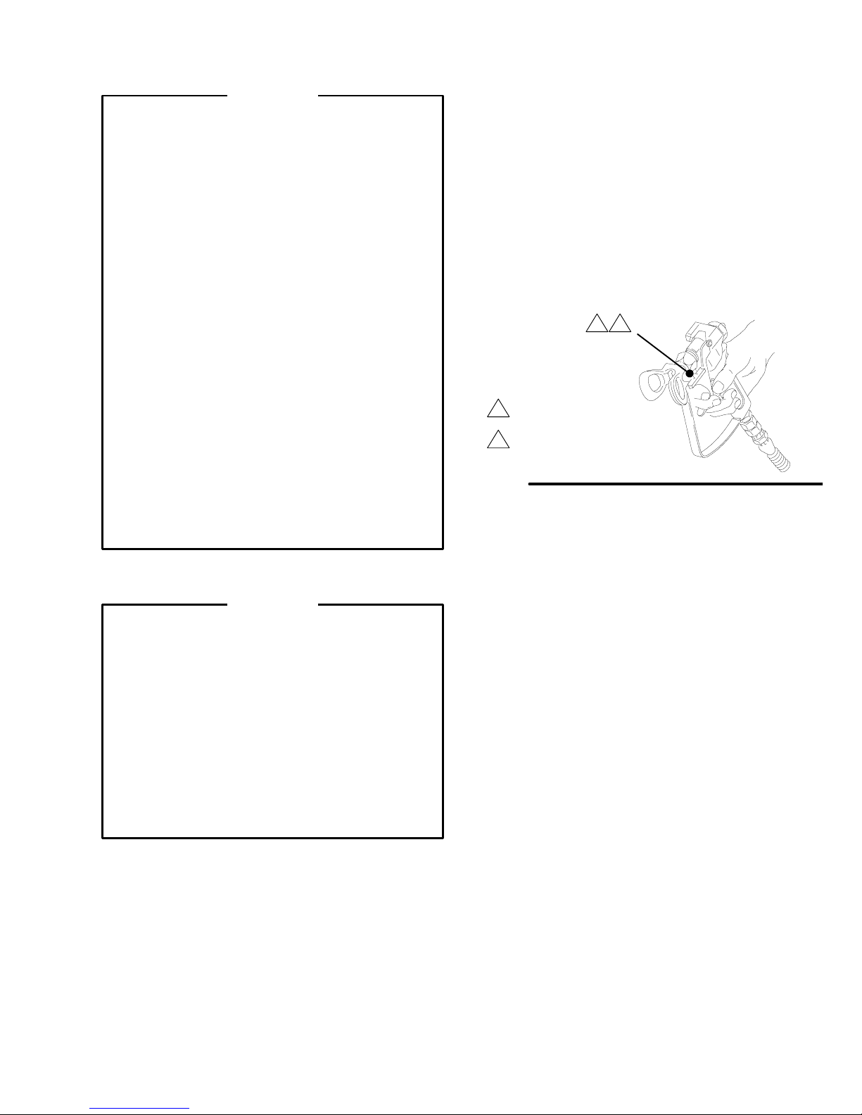
How to use the gun safety latch
When
engaged, the gun safety latch prevents the gun
from accidental triggering. See Fig. 2.
WARNING
If the gun still sprays when the gun safety latch is
engaged, adjust the gun. See manual 307–614,
supplied.
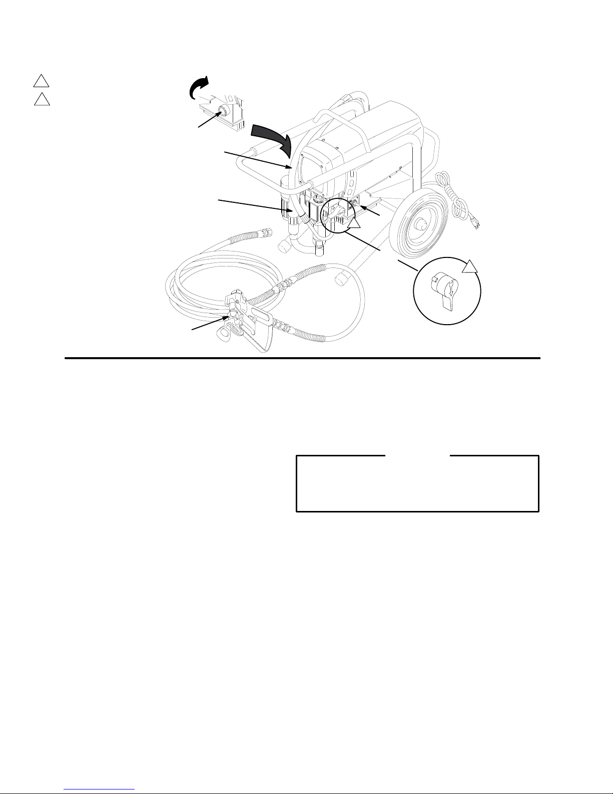
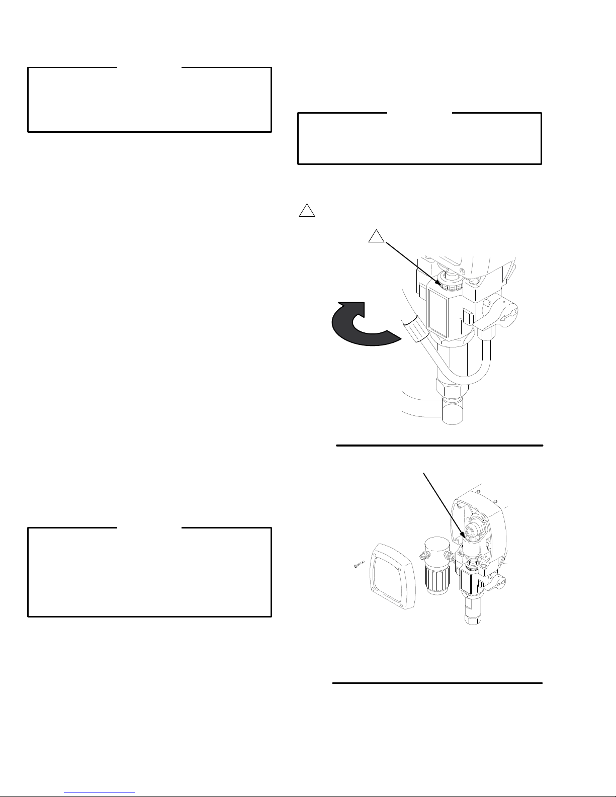
How to use the pressure drain valve
How to use the pressure control
The
pressure control controls the motor operation so
the sprayer maintains constant fluid pressure at the
pump outlet. T
terclockwise to obtain the minimum setting. T
’s
knob clockwise to increase pressure. See Fig. 4.
-
“ON
“OFF SAFE”
Fig.
2
Fig.
3
urn the pressure control knob fully coun
SAFE”
Closed,
or
spray position
Open or
drain, position
-
urn the
01020
02985
Use
the pressure drain valve to relieve fluid pressure
from the pump and to help prime the pump. If the valve
senses an over pressure condition, it opens automati
cally to relieve fluid pressure. If this happens, stop
spraying immediately, shut of
Determine the cause of the problem and correct it be
f and unplug the sprayer
fore operating the sprayer again. Refer also to the
T
roubleshooting Guide, page 17. See Fig. 3.
+
Rotate
.
to increase (+)
or decrease (–)
pressure
Fig. 4
–
02986
Page 11
Setup
WARNING
Pressure
T
o reduce the risk of serious bodily injury
fluid injection, splashing fluid or solvent in the eyes
or on the skin, or injury from moving parts or elec
tric shock, always follow this procedure when you
shut of
the spray system, install, clean or change spray
tips, and whenever you stop spraying.
1.
2. T
3.
4.
5.
6.
If you suspect that the spray tip or hose is com
pletely clogged, or that pressure has not been fully
relieved after following the steps above,
SLOWL
coupling to relieve pressure gradually
completely.
Relief Procedure
, including
f the sprayer
, check or service any part of
Engage the gun safety latch.
urn the ON/OFF switch to OFF
Unplug the sprayer
.
.
Disengage the gun safety latch. Hold a metal
part of the gun firmly to the side of a grounded
metal pail. T
rigger the gun to relieve pressure.
Engage the gun safety latch.
Open the pressure drain valve. Leave it open
until you are ready to spray again.
VER
Y
Y loosen the tip guard retaining nut or hose
, then loosen
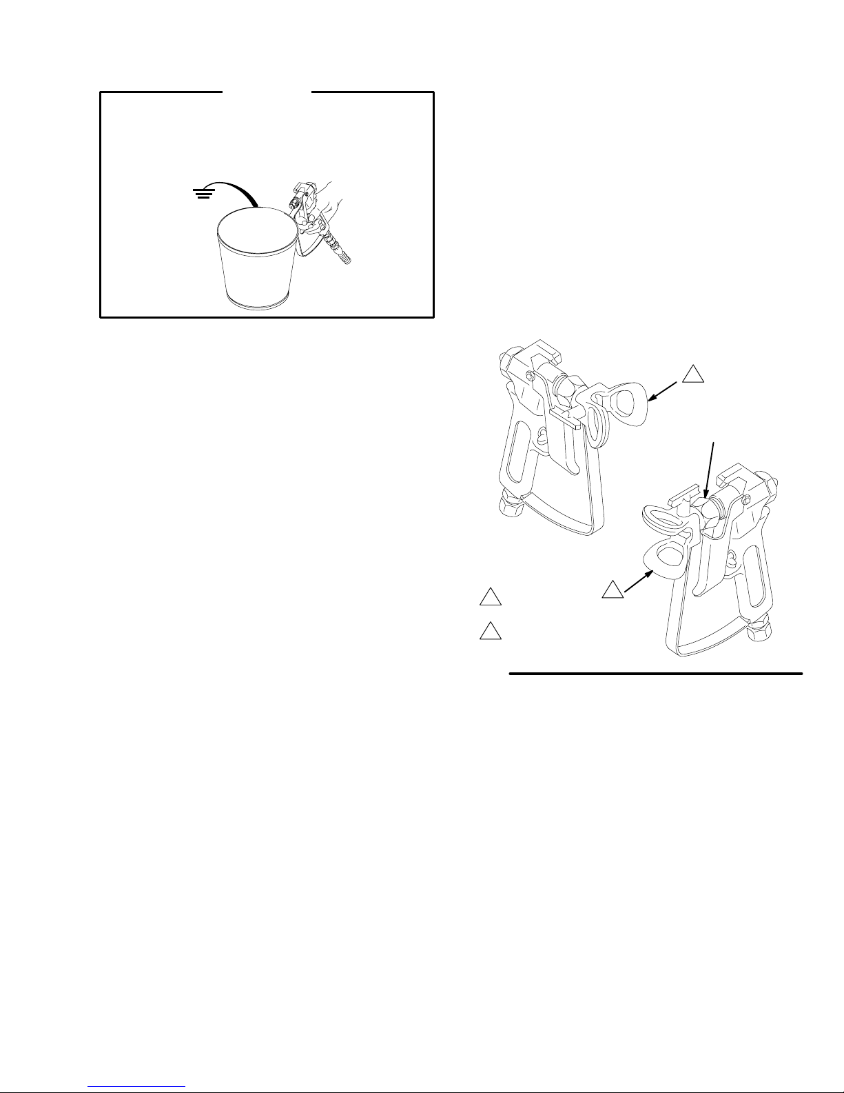
How to use the RAC IV tip guard
The tip guard alerts you to the risk and helps prevent
placing any part of the body close to the spray tip. The
tip guard also adjusts the vertical or horizontal spray
pattern. See page 13. The tip guard holds a reversing
-
spray tip. The tip is in the spraying position when the
tip handle points forward. See Fig. 5.
Clean the front of the tip frequently during the day’
operation. First, follow the
Pressure Relief Procedure
s
Warning, left.
Tip
Handle shown in
spraying position.
T
urn handle 180
-
trigger gun to clear clog
Fig. 5
,
01023
How to remove a tip clog
1. Release
Rotate the RAC IV tip handle 180. See Fig. 5.
the gun trigger
. Engage the safety latch.
WARNING
To
reduce the risk of serious bodily injury from fluid
injection:
NEVER operate the spray gun with the tip guard
removed.
DO NOT hold your hand, body
the spray tip when cleaning or checking a clogged
tip. Always point the gun toward the ground or into
a pail when checking to see if the tip is clear
DO NOT try to “blow back” paint; this is NOT an air
spray sprayer
.
, or a rag in front of
.
2.
Disengage the safety latch. T
rigger the gun into a
pail or onto the ground to remove the clog.
3.
Engage the safety latch. Rotate the tip handle to
the spraying position.
4.
If the tip is still clogged, engage the safety latch,
shut of
f and unplug the sprayer
, and open the
pressure drain valve to relieve pressure. Clean the
spray tip as shown in manual 307–848, supplied.
Page 12
in closed, or spray position.
Shown
Open, or drain position
Startup
+
–
E
D
C
B
Fig. 6
Use
this procedure each time you start the sprayer to
help ensure the sprayer is ready to operate and that
you start it safely
NOTE:
See page 15.
1.
2. Don’t install the spray tip until the pump is
If this is a first–time startup, flush the sprayer
Open the pressure drain valve (A).
primed!
.
See Fig. 6.
F
A
02984
4. T
urn the pressure knob (E) to the minimum
setting.
5. Disengage the gun safety latch.
.
page 10.
See Fig. 2,
CAUTION
T
o reduce the risk of damage to the displacement
pump packings, never run the pump without fluid in
it for more than 30 seconds.
3. Put the suction hose (C) into the paint
are pumping from a 1 gallon (5 liter) pail, push the
drain hose (D) down below the top of the pail to
avoid splashing paint when the drain valve is
opened.
. If you
6. T
o prime the pump,
on. Slowly increase the pressure until the sprayer
starts. When fluid comes from the pressure drain
valve, close the valve.
turn the sprayer switch (F)
Page 13
Startup
WARNING
T
o reduce static sparking and splashing when
priming, be sure the spray tip is not installed on the
gun, and hold a metal part of the gun firmly to the
side of a grounded metal pail.
b.
If more coverage is needed, use a larger tip
rather than increasing the pressure.
c. T
est the spray pattern. T
o adjust the direction
of the spray pattern, engage the gun safety
latch and loosen the retaining nut (B). Position
the tip guard horizontally for a horizontal pat
tern or vertically for a vertical pattern. Hold the
tip guard in place while tightening the retaining
nut. See Fig. 7.
-
7. T
o prime the hose
, lower the pressure to reduce
splashing. Holding the gun against the pail, trigger
the gun and slowly increase the pressure until the
pump starts. Keep the gun triggered until all air is
forced out of the system and the fluid flows freely
from the gun. Release the trigger and engage the
gun safety latch.
8. Check all fluid connections for leaks
. Relieve
pressure before tightening any connections.
9. Install the spray tip.
Engage the gun safety latch
first! See manual 307–848 for how to install the tip.
10. Adjust the spray pattern
Increase the pressure just until spray from the
a.
gun is completely atomized. T
o avoid exces
sive overspray and fogging, and to extend tip
and sprayer life, always use the lowest pres
sure needed to get the desired results.
01024
-
-
NOTE:
Spray patterns will change as tips wear
.
Change the spray tip if adjusting the pressure will not
improve the spray pattern.
B
Fig.
For a vertical
spray pattern
For
a horizontal
spray pattern
7
01025
Page 14
Shutdown
and Care
WARNING
To
reduce the risk of serious bodily injury
follow the
page 3 when instructed in this procedure to
relieve pressure.
1. Check the packing nut/wet-cup daily.
pressure first. Keep the wet-cup 1/3 full of TSL at
all times to help prevent fluid buildup on the piston
rod and premature wear of packings.
2. Tighten the packing nut/wet-cup just enough
to stop leakage.
and excessive packing wear
or brass rod and a light hammer to adjust the nut.
See Fig. 8.
3. Clean the gun’s fluid filter often
the gun is stored. Relieve pressure first. Refer to
manual 307–614.
Pressure Relief Procedure W
Over-tightening causes binding
. Use a round punch
, always
arning
and whenever
on
Relieve
7. Coil the hose
to help protect the hose from kinking, abrasion,
coupling damage, etc.
when storing it, even for overnight,
WARNING
See the warning section
4 for information on the hazard of using damaged
hoses.
Turn
nut
clockwise
tighten
packing
to
HOSE SAFETY
on page
4. Lubricate the bearing housing
hours of operation. Remove the front cover
several drops of SAE 10 non-detergent oil in the
bearing housing cavity (B). See Fig. 9.
5. Flush the sprayer at the end of each work day
and fill it with mineral spirits to help prevent pump
corrosion and freezing. See page 15.
after every 100
. Apply
CAUTION
T
o prevent pump corrosion, and to reduce the
chance of fluid freezing in the pump in cold
weather
the sprayer when it is not in use. Freezing can seri
ously damage the sprayer or result in a loss of
pressure or stalling.
6. For very short shutoff periods,
, never leave water or any type of paint in
leave the suction
hose in the paint, relieve pressure, and clean the
spray tip.
Fig.
8
02988
B
-
Fig. 9
02989
14 308-319
Page 15

Flushing
When to flush
Determine
Column 1, then flush with the material indicated in the
Column 2, then, depending on what you plan to do
next, follow the recommendations in one of the next
three columns.
If you are going to: Flush with:
Spray latex paint
Spray oil paint
Change latex to oil paint
Change oil to latex paint
Change colors, same base
the material you are going to pump from the
Column 1
Column 2 Column 3 Column 4 Column 5
W
arm, soapy water
then clean water
Mineral spirits
W
arm, soapy water
then clean water
Mineral spirits,
soapy water
clean water
Compatible solvent
such as water or
mineral spirits
, and
.
,
,
CAUTION
NEVER leave water or water-based fluids in the
sprayer if there is a chance it could freeze. Push
the water out with mineral spirits. Frozen fluid in
the sprayer prevents it from being started and may
cause serious damage.
Prime with:
Latex-base paint
Oil–base paint
Mineral spirits Mineral spirits Mineral spirits
Latex W
Clean with: Store unit with:
W
arm soapy water
then clean water
Mineral spirits Mineral spirits
arm, soapy water
then clean water
,
Mineral spirits
,
Mineral spirits
How to flush
1. Follow Pressure Relief Procedure
Remove the spray tip and clean it separately
2.
you are changing from water–based to oil–based
paints or solvents, be sure that the tip is cleaned
thoroughly.
3.
Remove the filter screen and then reinstall the
bowl, hand tight, without the screen. Clean the
screen separately
BOWL
Fig. 10
. See Fig. 10.
. See page 1
SCREEN
. If
1.
02990
4.
Pour one-half gallon (2 liters) of compatible solvent
into a grounded metal flushing pail. Put the suction
hose in the pail.
5.
Open the pressure drain valve. See Fig.1
6. To save the paint still in the pump and hose,
follow Step 7, except put the drain hose in the
paint pail. When solvent appears, close the drain
valve. Put the drain hose in the flushing pail. T
ger the gun into the paint pail. When solvent ap
pears, release the trigger
. Continue with Step 7.
1.
rig-
-
308-319 15
Page 16

WARNING
T
o reduce static sparking and splashing, always
remove the spray tip from the gun, and hold a
metal part of the gun firmly to the side of a
grounded metal pail when flushing.
7.
Lower the pressure setting. T
Maintaining metal-to-metal contact, trigger the gun
into the flushing pail. Slowly increase the sprayer
pressure just until the pump starts. Keep the gun
triggered until the solvent flows freely from the
gun. Circulate the solvent to thoroughly clean the
sprayer
. Release the gun trigger
safety latch.
urn on the sprayer
. Engage the gun
Flushing
9.
Remove the suction hose from the pail. Disengage
the gun safety latch. T
pump a few seconds to push air into the hose. Do
not run the pump dry for more than 30 seconds to
avoid damaging the pump packings! Relieve pres
sure.
10.
Reinstall the clean filter screen.
11.
Remove and clean the inlet strainer
the suction hose and drain hose.
12.
Leave the drain valve open until you use the
01024
.
sprayer again.
Open
drain position
or
rigger the gun and run the
. Wipe paint of
-
f
8.
Open the drain valve and circulate the solvent
through the drain hose to thoroughly clean it.
Close the drain valve.
Fig. 11
02987
16 308-319
Page 17

Troubleshooting
WARNING
T
o reduce the risk of serious injury
the
Pressure Relief Procedure
checking or repairing any part of the sprayer
, always follow
on page 3 before
.
Check everything in the guide before disassembling
the sprayer
.
Basic Problem Solving
TYPE OF
PROBLEM
Fluid Pressure 1.
Mechanical 1.
WHA
T T
O CHECK
If check is OK, go to next check
Check pressure transducer knob setting. The
pump won’t develop much pressure if it is at mini
mum setting (fully counterclockwise).
2.
Check for a clogged spray tip or fluid filter
See page 1
Check for frozen or hardened paint in pump (20).
Using a screwdriver
back of motor by hand. See page 28.
1.
, carefully try to rotate fan at
NOTE:
Thaw sprayer if water or water–based paint
has frozen in it, due to exposure to low temperatures,
by placing it in a warm area. Do not try to start sprayer
until it has thawed completely or damage to motor and/
or control board may occur. If paint hardened (dried) in
sprayer
, the pump packings and/or pressure transduc
er must be replaced. See page 24 (pump) or 32 (pres
sure transducer).
WHA
T T
O DO
When
check is not OK, refer to this column
1.
-
, if used.
Slowly increase pressure setting to see if
motor starts.
2.
If tip is still clogged, relieve pressure;
refer to separate gun or tip instruction
manual for tip cleaning. Clean or replace
filter element. See manual 308–249.
1. Thaw
. Plug in sprayer and turn on.
Slowly increase pressure setting to see if
motor starts. If it doesn’t, see NOTE
above.
-
-
Electrical 1.
2.
Check pump connecting rod pin (17). It must be
completely pushed into connecting rod (15), and
retaining spring (18) must be firmly in connecting
rod groove. See Fig. 18, page 24.
3.
Check for motor damage. Remove drive housing
assembly (1
fan by hand.
Check electrical supply with volt meter
should read 105–125 V
2.
Check extension cord for visible damage. Use a
voltmeter or test lamp at extension cord outlet to
check.
3. Check sprayer power supply cord (50) for visible
damage such as broken insulation or wires.
4.
Check motor brushes for the following:
a.
Loose terminal screws.
b.
Broken or misaligned brush springs.
c.
Brushes binding in holders.
d.
Broken leads.
e. W
f.
Brush leads snagged on spring clip.
NOTE:
rate on both sides of motor
brushes.
1). See page 30. T
orn brushes.
The brushes do not wear at same
ry to rotate motor
AC.
. Check both
. Meter
2.
Push pin into place and secure with
spring retainer
3.
Replace motor (4) if fan won’t turn. See
page 28.
1.
Reset building circuit breaker; replace
building fuse. T
2.
Replace extension cord.
3.
Replace power supply cord. See page
29.
4.
Refer to page 23.
a. Tighten.
b.
Replace broken spring and/or align
spring with brush
c.
Clean brush holders. Remove carbon
with small cleaning brush. Align brush
leads with slot in brush holder to as
sure free vertical brush movement.
d.
Replace brushes
e.
Replace brushes if less than 0.4”
(10 mm) long.
f. Correctly rout
.
ry another outlet.
e the w
ires
. See page 2
-
3.
5.
Check motor armature commutator for burn spots,
gouges and extreme roughness. Remove motor
cover and brush inspection plates to check. See
page 23.
6.
Check motor armature for shorts using armature
tester (growler) or perform motor test. See page
22.
5.
Remove motor and have motor shop
resurface commutator if possible. See
page 28.
6.
Replace motor
. See page 28.
308-319 17
Page 18

Basic Problem Solving
TYPE OF
PROBLEM
Electrical
(continued)
WHA
T T
O CHECK
If check is OK, go to next check
7.
Check leads from pressure transducer and motor
to motor control board (47) to be sure they are se
curely fastened and properly mated.
8.
Check motor control board (47) by substituting with
a good board.
CAUTION:
armature is determined to be good. A bad motor
armature can burn out a good board.
9. Check power supply cord (50). Disconnect black
and white power cord terminals; connect volt
meter to these leads. Plug in sprayer
read 105–125 V
10. Check ON/OFF switch (52). Disconnect the “L”
wire between motor control board (47) and switch
and connect volt meter between exposed terminal
switch and power cord’
sprayer and turn ON. Meter should read 105–125
VAC. T
11.
Check motor thermal cutout switch. Connect ohm
meter between motor’s red leads. Meter should
read 1 ohm maximum.
12.
Check the transducer (29) by replacing it with a
new one.
Do not perform this check until motor
AC. Unplug sprayer
urn of
f and unplug sprayer
s white wire. Plug in
. Meter should
.
.
WHA
T T
O DO
When check is not OK, refer to this column
7.
-
-
Replace loose terminals; crimp to leads.
Be sure male terminal blades are straight
and firmly connected to mating part.
8.
Replace board. See page 29.
9.
Replace power supply cord. See page
29.
10.
Replace ON/OFF switch. See page 29.
11.
Allow motor to cool. Correct cause of
overheating. If switch remains open after
motor cools, replace motor
12. Replace pressure transducer
32.
.
. See page
TYPE OF
PROBLEM
Low Output
13.
Check pressure adjustment potentiometer (64) by
replacing it with a new one.
Intermediate Problem Solving
WHA
T T
O CHECK
If check is OK, go to next check
1. Check for worn spray tip. 1.
2.
Be sure pump does not continue to stroke
when gun trigger is released. Plug in and
turn on sprayer
mentarily
Relieve pressure, turn of
3.
Release gun trigger
pump rod (107).
4.
Check electrical supply with volt meter
should read 105–125 V
5.
Check extension cord size and length.
. Prime with paint. T
, then release and engage safety latch.
f and unplug sprayer
. Observe resting position of
AC.
rigger gun mo
.
. Meter
-
WHA
T T
O DO
When check is not OK refer to this column
Follow
Pressure Relief Procedure
W
arning
separate gun or tip manual.
2.
Service pump. See page 24.
3.
If pump consistently comes to rest
with rod (107) fully extended, the piston
packings and/or piston valve may be
worn. Service the pump. See page 24.
4.
Reset building circuit breaker; replace
building fuse. Repair electrical outlet or
try another outlet.
5.
Replace with a correct, grounded exten
sion cord. Note that long lengths and/or
smaller gauges reduce performance.
then replace tip. See your
-
6.
Check motor brushes. See Electrical – What T
Check, item 4, on page 17.
o
6.
See page 23.
Page 19

Intermediate Problem Solving
TYPE OF
PROBLEM
Low Output
(continued)
Drain V
No Output: Motor
Runs And Pump
Strokes
alve Leaks 1.
WHA
T T
O CHECK
If check is OK, go to next check
7. Check
8. Check
1.
2.
3.
4.
motor control board (47) by substituting with
a good board.
CAUTION:
armature is determined to be good. A bad motor
armature can burn out a good board.
ture tester (growler) or perform motor test. See
page 22.
Check drain valve for correct torque and/or worn
parts. Check for debris trapped on seat.
Check paint supply
Check for clogged intake strainer
Check for loose suction tube or fittings. See
page 34.
Check to see if intake valve ball and piston ball are
seating properly
Do not perform this check until motor
motor armature for shorts by using an arma
. 1.
. 2.
. See page 24.
WHA
T T
O DO
When check is not OK, refer to this column
7.
Replace board. See page 29.
-
8.
Replace motor
1. T
ighten to 185 in–lb (21 N.m). Clean
valve and replace with new gasket (42a)
and sealant (42e). See page 35.
Refill and reprime pump.
Remove and clean, then reinstall.
3. T
ighten; use thread sealant on
npt threads of inlet tube (38). Check for
damaged o–ring (27).
4.
Remove intake valve and clean. Check
ball and seat for nicks; replace as need
ed. See page 24. Strain paint before us
ing to remove particles that could clog
pump.
. See page 28.
-
-
No Output: Motor
Runs But Pump
Does Not Stroke
Spray Pattern
Variations
5.
Check for leaking around throat packing nut
which may indicate worn or damaged packings.
See page 24.
6.
Release gun trigger
pump rod (107).
1.
Check displacement pump connecting rod pin (17).
See Fig. 18, page 24.
2.
Check connecting rod assembly (15) for damage.
See page 30.
3.
Be sure crank in drive housing rotates; plug in
sprayer and turn on briefly to check. T
unplug sprayer
1.
Spray tip worn beyond sprayer pressure capability
2.
Check motor control board by replacing it with a
new one.
3.
Check pressure transducer (64) by replacing it
with a new one.
. Observe resting position of
urn of
. See page 30.
f and
5.
Replace packings. See page 24. Also
check piston valve seat for hardened
paint or nicks and replace if necessary
T
ighten packing nut/wet-cup.
6.
If pump consistently comes to rest
with rod (107) fully extended, the piston
packings and/or piston valve may be
worn. Service the pump. See page 24.
1.
Replace pin if missing. Be sure retainer
spring (18) is fully in groove all around
connecting rod.
2.
Replace connecting rod assembly
page 30.
3.
Check drive housing assembly for dam
age and replace if necessary
30.
. 1.
Replace spray tip.
NOTE:
longer life.
2.
3. Replace pressure transducer
A smaller size tip will provide
Replace board. See page 29.
32.
.
. See
-
. See page
. See page
Page 20

Intermediate Problem Solving
Switch Is Turned
TYPE OF
PROBLEM
Spray Pattern
Variations
(continued)
Motor Is Hot and
Runs Intermittently
Building Circuit
Breaker Opens As
Soon As Sprayer
Switch Is Turned
On.
WHA
T T
O CHECK
If check is OK, go to next check
4.
Check pressure adjustment potentiometer (64) by
replacing it with a new one.
5.
Check Low Output section, page 18.
1. Determine
with
up.
2.
Be sure ambient temperature where sprayer is lo
cated is no more than 90F (32
not located in direct sun.
3. Check motor. 3.
1.
Check all electrical wiring for damaged insulation,
and all terminals for loose fit or damage.
Also check wires between pressure transducer
and motor
2.
Check for missing motor brush inspection plate
gasket (see page 23), bent terminal forks or other
metal to metal contact points which could cause a
short.
3.
Check motor armature for shorts. Use an
armature tester (growler) or perform motor test.
See page 18. Inspect windings for burns.
if sprayer was operated at high pressure
small tips, which causes excessive heat build
-
C) and sprayer is
. See page 28.
WHA
T T
O DO
When check is not OK, refer to this column
1.
Decrease pressure setting or increase tip
size.
2.
Move sprayer to shaded, cooler area if
possible.
Replace motor
1.
Repair or replace any damaged wiring or
terminals. Securely reconnect all wires.
2.
Correct faulty conditions.
3.
Replace motor
. See page 28.
. See page 28.
Circuit breaker
opens after sprayer
operates for 5 to 10
minutes.
Building circuit
breaker opens as
soon as sprayer is
plugged into outlet
and sprayer is NOT
turned on.
Unit will not run on
generator but does
run on AC power
4.
Check motor control board (47) by substituting with
a good board.
CAUTION:
armature is determined to be good. A bad motor
armature can burn out a good board.
1.
Check ‘Basic Problems – Electrical’ on page 17.
1. Check ON/OFF switch (52). Be sure sprayer is
unplugged! Disconnect wires from switch. Check
switch with ohmmeter
infinity with ON/OFF switch OFF
switch ON.
CAUTION:
switch and or motor control board (47).
2.
Check for damaged or pinched wires in junction
box (59).
1.
Check the generator
will not run if the peak voltage is above 190V or
below 100V
Do not perform this check until motor
. The reading should be
, and zero with
A short in motor circuit can damage
’s “peak” voltage. This sprayer
.
4.
Replace board. See page 29.
1.
Replace ON/OFF switch. See page 29.
2.
Replace damaged parts.
1.
Use AC power or a dif
ferent generator
.
Page 21

General
Repair Information
WARNING
Pressure
T
o reduce the risk of serious bodily injury
fluid injection, splashing fluid or solvent in the eyes or
on the skin, or injury from moving parts or electric
shock, always follow this procedure whenever you
shut of
spray system, install, clean or change spray tips, and
whenever you stop spraying.
1.
2. T
3.
Relief Procedure
f the sprayer
Engage the gun safety latch.
urn the ON/OFF switch to OFF
Unplug the power supply cord.
, check or service any part of the
, including
.
4.
Disengage the gun safety latch. Hold a metal
part of the gun firmly to the side of a grounded
metal pail, and trigger the gun to relieve pres
sure.
5.
Engage the gun safety latch.
6.
Open the pressure drain valve, having a con
tainer ready to catch the drainage. Leave the
valve open until you are ready to spray again.
If you suspect that the spray tip or hose is completely
clogged, or that pressure has not been fully relieved
after following the steps above,
loosen the tip guard retaining nut or hose coupling to
relieve pressure gradually
Now clear the tip or hose.
VER
Y SLOWL
, then loosen completely
-
-
Y
.
Tool List
These
service tools are required.
1/4” Allen wrench:
3/8” Allen wrench:
3/16” Allen wrench:
5/64” Allen wrench:
#1 Phillips screwdriver:
motor shield
3/8” socket wrench:
5/8” socket wrench:
on/off switch boot, piston
13/16” socket wrench:
1-1/4” socket wrench:
1/2” open end wrench:
1
1/16” open end wrench:
15/16” open end wrench:
1-3/4” open end wrench:
5/64” drive pin:
3” needle nose pliers:
Hammer & punch:
T
orque wrenches:
filter plug
pump manifold
gear housing, legs, handle
pressure adjustment knob
junction box, front cover
motor mount
drain valve, outlet fittings,
drain valve
pump inlet valve
pump rod
piston jam nut
flats of inlet tube
pump jam nut
drain valve pin
wiring, on/off switch
packing nut
various fasteners
CAUTION
T
o reduce the risk of a pressure transducer mal
function, properly mate connectors and never pull
on a wire to disconnect it.
CAUTION
Improper wire routing can result in poor sprayer
performance or damage to the pressure trans
ducer.
4.
Keep all screws, nuts, washers, gaskets, and
,
electrical fittings
dures.
5. T
est your repair before regular operation
sure the problem is corrected.
6.
If the sprayer does not operate properly
that everything was done correctly. Also refer to
the T
roubleshooting Guide, page 17, to help iden
tify other possible problems and solutions.
removed during repair proce
-
-
to be
, verify
-
WARNING
T
o reduce the risk of serious bodily injury
electric shock, DO NOT touch any moving parts or
electrical parts with your fingers or a tool while in
specting the sprayer
Shut of
complete the inspection.
f the sprayer and unplug it as soon as you
.
, including
-
1. When disconnecting wires
pliers to separate mating connectors.
2.
When reconnecting wires
of the male connector in the blade of the female
connector.
Route wires carefully
3.
wires between covers.
and avoid pinching any
, use needle nose
, center the flat blade
Reinstall all covers, gaskets, screws and washers
before operating the sprayer
.
WARNING
During operation, the motor and drive housing be
come very hot and could burn your skin if touched.
Flammable materials spilled on the hot, bare motor
could cause a fire or explosion.
-
Page 22

Motor
T
est
WARNING
To
reduce the risk of serious injury
sure Relief Procedure W
fore doing this procedure. Unplug the sprayer!
For checking armature, motor winding and brush elec
trical continuity
.
arning
, follow the
on page 3 be
Pres-
-
Setup
Remove the drive housing. See page 30. This is to
ensure that any resistance you notice in the armature
test is due to the motor and not to worn gears in the
drive housing.
Remove the motor brush inspection covers (A). See
Fig. 13.
Remove the screws (56,75). Lower the control board
(47). Disconnect the two leads (C) from the motor to
the board. See Fig.12.
Armature Short Circuit Test
Remove
Spin the motor fan by hand. If there are no shorts, the
motor will coast two or three revolutions before coming
to a complete stop. If the motor does not spin freely
the armature is shorted and the motor must be re
placed. See page 28.
the fan cover (B). See Fig.13.
,
-
When turning the fan on a DC motor, normally you
sense an even, pulsing resistance. If there is irregular
turning resistance, or no turning resistance, check and
repair the following as needed: broken brush springs,
brush leads, motor leads; loose brush terminal screws
or motor lead terminals; worn brushes. See page 23.
If there is still uneven or no turning resistance, replace
the motor
. See page 28.
B
A
Armature, Brushes, and Motor Wiring
Open Circuit Test (Continuity)
Connect
test lead. T
revolutions per second. See Fig. 12.
52
the two black motor leads (C) together with a
urn the motor fan by hand at about two
MOT
OR (4)
50
49
P
C
D
64
47
29
Fig. 13
9
02991
Fig. 12
03000
Page 23

Motor
Brush
NOTE: Replace brushes when worn to about 0.4 in.
(10 mm). Always check both brushes. Brush Repair Kit
235–727 is available.
NOTE:
long as the original ones. T
break in new brushes by operating the sprayer with no
load (remove the pump connecting rod pin) for at least
1 hour
Replacement brushes may last only half as
o maximize brush life,
.
WARNING
T
o reduce the risk of serious injury
sure Relief Procedure W
fore doing this procedure. Unplug the sprayer!
1.
Remove the motor shield (2).
2.
Remove both inspection covers (A) and their gas
kets. See Fig. 14.
arning
, follow the
on page 21 be
A
Pres-
-
-
4.
Loosen
brush lead (D) away
minal (B) in place. Remove the old brush. See Fig.
15.
5.
Inspect the commutator for excessive pitting, burn
ing or gouging. A black color on the commutator is
normal. Have the commutator resurfaced by a
qualified motor repair shop if the brushes seem to
wear too fast or arc excessively
also.
Repeat for the other side.
6.
7.
Place a new brush (C) in the holder (A). Slide the
terminal under the terminal screw washer (E). En
sure the motor lead (B) is still connected at the
screw. T
8.
Holding the spring/clip (F) at a slight angle, slide
the spring/clip into the brush holder and hook it
over the end of the holder (G). See Fig. 16. Pull on
the spring/clip to be sure it stays in place. Be sure
the brush lead is tucked under the spring/clip tab.
9.
Repeat for the other side.
10. Test the brushes.
a.
b.
c. T
d.
the brush lead terminal screw (E). Pull the
, but leave the motor lead ter
. See Step 10.d..
ighten the screw
Remove the pump connecting rod pin.
With the sprayer OFF
ducer knob fully counterclockwise to minimum
pressure. Plug in the sprayer
urn the sprayer ON. Slowly increase the
pressure until the motor is at full speed.
Inspect the brush and commutator contact
area for excessive arcing. Arcs should not
“trail” or circle around the commutator surface.
. See Fig. 15.
, turn the pressure trans
.
-
-
-
-
Do not touch the brushes, leads, springs or brush
holders while the sprayer is plugged in to reduce
Fig. 14
3.
Push in the spring/clip (F) and release its hooks
from the brush holder (A). Pull out the spring/clip.
See Fig. 15.
A
B
C
Fig. 15 Fig. 16
D
E
02992
0.4
in. (10 mm) Minimum
Spring/Clip P
F
01065 01066
the risk of electric shock and serious bodily injury
11.
Install the brush inspection covers and gaskets.
12.
Break in the brushes.
least one hour with no load. Install the pump
connecting rod pin.
.N.111–610
WARNING
.
Operate the sprayer for at
G
F
C
Page 24

Displacement
Pump
WARNING
To
reduce the risk of serious injury
sure Relief Procedure W
arning
fore doing this procedure. Unplug the sprayer!
NOTE:
Packing Repair Kit 235–703 is available. Refer
ence numbers of parts included in the kit are marked
with an asterisk, i.e., (121*). For the best results, use
all the new parts in the kit, even if the old ones still look
good.
NOTE: To minimize down time, and for the best spray
er performance, check the motor brushes (see page
23) and clean the transducer (see page 32) whenever
you repack the pump. Replace these parts as needed.
Removing the pump
1.
Flush the pump, if possible. Relieve pressure. Stop
(See Fig.17)
the pump with the piston rod (107) in its lowest
position, if possible. T
ally
, rotate the motor fan blades.
o lower the piston rod manu
, follow the
Pres-
on page 21 be
-
WARNING
Be sure the retaining spring (18) is firmly in the
groove all the way around, to prevent the pin (17)
from working loose due to vibration. See Fig. 18.
If the pin works loose, it or other parts could break
of
-
-
-
f due to the force of the pump action. These
parts could be projected into the air and result in
serious injury or property damage, including the
pump connecting rod or bearing housing.
3.
Replace the o-ring (27) if it is worn or damaged.
See page 34. Reconnect the suction and drain
hoses (32,33). Install the front cover (13).
TORQUE TO
13
17
Apply pipe
sealant (42e)
50 ft–lb
(68 N.m)
2.
Remove the filter (85).
3.
While pulling upward on the suction hose (32), un
screw the hose from the inlet tube (38). Unscrew
the drain hose (33) from the displacement pump
nipple (36).
NOTE:
to
4.
If repairing only the intake valve assembly
Intake valve repair, on page 25.
Use a screwdriver to push the retaining spring (18)
up and push out the pin (17).
5.
Loosen the screws (21). Remove the pump (20).
Installing the pump
1.
Lightly grease or oil the transducer (29). See Fig
(See Fig. 17 and 18)
ure XX. Guide the pump over the alignment pins
and pressure transducer
soft hammer
. T
ighten the screws (21) to 50 ft-lb
. T
ap it into position with a
(68 N.m).
, go
18
85
21
107
36
120
*122
*121
20
*119
118
32
27
38
Fig. 17
33
02993
17
15
-
TORQUE TO
50 ft–lb (68 N.m)
123
18
Align the hole in the rod (107) with the connecting
2.
rod assembly (15). Use a screwdriver to push the
retaining spring (18) up and push in the pin (17).
Push the retaining spring (18) into place around
the connecting rod.
Fig.
18
21
102
01068
Page 25

4. Tighten
leakage, but no tighter
the packing nut (102) just enough to stop
. Fill the packing nut/wet-cup
1/3 full with Graco TSL. Push the plug (123) into
the wet-cup.
2.
Stack these parts onto the piston valve (108) one
at a time: the backup washer (126*) and u–cup
(125*), the female gland (1
plastic (1
12*) with two leather packings (1
14*), alternately three
and the male gland (111*). See Fig. 20.
13*),
Intake valve repair
1.
Remove the suction hose. See Step 3,
(See Fig. 17)
Removing
the pump.
2.
Unscrew the intake valve (1
o-ring (1
19*), ball guide (120), stop pin (122*) and
18). Remove the
ball (121*) from the valve.
3.
Clean and inspect the parts for wear or damage.
Replace parts as needed. Use a new o–ring
(1
19*). If no further service is needed, reassemble
the pump.
Disassembling the pump
1.
Remove the intake valve (1
2.
Loosen the packing nut (102) and plug (123).
3.
Use a plastic mallet to tap the piston rod (107)
(See Fig. 19)
18).
down, and then pull the rod out through the bottom
of the cylinder
.
3. T
ighten the nut (110) onto the piston valve (108) to
2 in-lb (0.23 N.m). See Fig. 21.
Note the alignment
(1
10). Maintain this alignment through Step 8.
4.
Clean all residue from the piston valve threads.
of the piston (108) to the nut
Apply one drop of adhesive, supplied, to the
threads.
Place the ball (109*) on the piston valve (108). See
5.
Fig. 20.
CAUTION
Step 8, tightening the piston valve into the rod, is
critical. Follow the procedure carefully to avoid
damaging the packings by overtightening.
6.
Hand tighten the valve into the piston rod just until
the nut (1
10) contacts the rod. See Fig. 21.
4.
Remove the packing nut (102) and throat
packings.
Loosen the jam nut (1
5.
(1
15) and the o-ring (1
6.
Clamp the flats of the piston rod in a smooth jaw
17). Remove the cylinder
16*).
vise. Use an open-end wrench to loosen the nut
(1
10) and then unscrew the piston valve (108).
7.
Remove all parts from the piston valve (108).
Reassembling the pump
NOTE:
Alternate plastic and leather packings. See Fig.
19. The lips of the throat V-packings face down. The
lips of the piston V–packings face up. The lips of seal
125* face down. Incorrect installation damages the
packings and causes pump leaks.
NOTE:
Soak the leather packings in oil before reas
-
sembling the pump.
101
*116
123
102
*103
127
117
115
*104
105*
*106
*113
*122
Lips
down.
Lips up.
107
109*
110
111
112*
114*
125*
126*
108
120
*121
*119
118
1.
Check the outside of the piston rod (107) and the
inside of the cylinder (1
15) for wear
parts to ensure a good seal with the new packings.
. Replace worn
Fig. 19
03149
Page 26

TORQUE TO
2 in-lb (0.23 N.m)
APPLY ONE DROP
OF SEALANT T
THREADS
O
110
*111
*113
*125
Fig.
20
DO NOT ALLOW NUT (1
T
T
ENING PIST
TORQUE
AGAINST ROD
T
O 19 FT–LB
(25 N.m)
Fig.
21
7. Place
*126
O MOVE RELA
ON (108) WHEN TIGHT–
TIVE T
ON AGAINST ROD.
NUT
10)
O PIS
-
110
the flats of the rod (107) in a smooth jaw
vise.
8. CAREFULLY
tighten the nut (1
ton rod to 19 ft-lb (25 N.m). See Fig. 21.
107
109*
112*
114*
108
107
108
10) against the pis
Use two wrenches to maintain the alignment men
-
tioned in Fig. 21.
9.
Stack these parts one at a time into the top of the
manifold (101): the male gland (106*), alternately
three plastic packings (104*) with two leather pack
ings (105*), and then the female gland (103*). See
Fig. 23.
10.
Install the packing nut (102) and plug (124), but
leave loose for now
11.
Place a new o–ring (1
. See Fig. 23.
16*) firmly in the cylinder
groove. See Fig. 22.
12.
Coat the piston rod and packings with oil. Carefully
slide the assembly
CYLINDER (1
13.
Put the manifold in a vise. Fully thread the jam nut
(1
17) onto the cylinder (115). Guide the rod/
INT
15)
. See Fig. 22.
O THE T
OP OF THE
cylinder assembly down through the manifold
(101). Screw the cylinder (115) into the manifold.
See Fig. 22.
14.
Place the ball guide (120), stop pin (122) and ball
(121*) in the cylinder (1
15). Screw the intake valve
into the cylinder and torque to 53 ft-lb (71 N.m).
This will also properly torque the cylinder into the
manifold. See Fig. 22.
15. T
orque the cylinder jam nut (1
17) to 73 ft–lb (98
N.m). See Fig. 22.
-
16.
Install the pump. See page 24.
Page 27

T
ORQUE JAM NUT (1
73 ft-lb (98 N.m)
TORQUE
O MANIFOLD (101) T
INT
53 ft-lb (71 N.m)
TORQUE INT
VAL
VE (1
O CYLINDER
INT
(115) T
O
53 ft-lb (71 N.m)
CYLINDER (1
AKE
18)
17)
15)
Lips
face down.
Lips face up.
TORQUE TO
O
53 ft-lb (71 N.m)
107
123
102
101
102
Fig.
22
107
116*
117
115
118
01072A
Fig.
LEATHER
LEATHER
23
*103
*105
*116
110
*111
*113
108
115
120
*119
118
PLASTIC
106*
101
117
PLASTIC
114*
126*
122*
121*
03147
104*
112*
125*
Page 28

WARNING
To
reduce the risk of serious injury
sure Relief Procedure W
arning
fore doing this procedure. Unplug the sprayer!
NOTE:
1.
2.
3. T
See Fig. 26 except where noted.
Relieve pressure.
Remove the motor shield (4).
ry to stop the pump with the piston rod (107) in its
lowest position. T
o lower the piston rod manually
rotate the motor fan blades. Use a screwdriver to
push the retaining spring (18) up and push out the
pin (17). See Fig. 24.
4.
Remove the shroud (4).
5.
Lift the connecting rod. Remove the screws
(56,75) and lower the control card (47). Disconnect
the motor wires and the pressure transducer wire
(A) from the motor control board. Refer to Fig. 26.
, follow the
on page 21 be
Motor
Pres-
-
,
11.
Align the new motor with the cart and reinstall the
screws (46).
12.
Assemble the drive housing to the motor
steps 8 to 14 on page NO
T
AG. Install the junction
. Follow
box.
13.
Connect the wires in the junction box. Refer to Fig.
12. Install the control card.
14.
Connect the piston rod (107) to the drive housing;
see page 24,
W
ARNING following it.
15.
Install the shroud (4).
Installing the Pump
, Step 2 and the
17
15
18
6.
Remove the drive housing cover (13). Remove
the control card (47), screws (71), and junction box
(59).
7. T
urn the displacement pump rod (107) so the pin
hole aligns with the bottom drive housing screw
(19). See Fig. 25. Remove the three drive housing
screws and lockwashers (19,6). See Fig. 25 and
26
.
8.
Remove the two motor screws and lockwashers
(5,6).
9. T
ap the lower rear of the drive housing (1
plastic mallet to loosen the motor
. Pull the drive
1) with a
housing straight off the motor while guiding the
harness (A) from the motor
. Do not allow the gear
(16) to fall. Read the CAUTION on page 30.
10.
Remove the two screws (46) and lift the motor of
the cart (1).
TORQUE TO
80 in–lb (9 N.m)
19
Fig. 24
01068
107
19,6
Fig. 25
01074
4
TORQUE TO
80 in–lb (9 N.m)
6
5
A
16
f
11
12
6
59
71
46
34
13
Fig.
26
47
56
75
02994
Page 29

Motor
WARNING
To
reduce the risk of serious injury
sure Relief Procedure W
fore doing this procedure. Unplug the sprayer!
1.
Remove the screws (56,75) and lower the control
card (47). See Fig. 26.
arning
, follow the
on page 21 be
Control Board
4.
Install the new motor control board. Reconnect all
Pres-
-
wires and secure it to the junction box (59).
CAUTION
Be sure the flat blade of the insulated male connec
tor is centered in the wrap–around blade of the fe
male connector when the connections are made.
-
-
2.
Disconnect the motor wires (C) and the two
connectors (D) from the motor control board (47).
Observe where connections are made. See Fig.
12.
Remove the screw (9) from the ground wire (G)
3.
and remove the board.
Power
WARNING
To
reduce the risk of serious injury
sure Relief Procedure W
fore doing this procedure. Unplug the sprayer!
1.
Remove the screws (56, 75) and lower the control
card (47). See Fig. 26.
2.
Disconnect the power supply cord leads (P), in
cluding the green wire to the grounding screw (9).
See Fig. 12.
arning
, follow the
on page 21 be
On/Off
Route all wires carefully to avoid interference with
the motor control board or junction box.
These precautions are essential to reduce the risk
of a malfunction.
Supply Cord
3.
Loosen the strain relief bushing (51). Remove the
Pres-
-
-
power supply cord (50).
4.
Install the new cord (50) in the reverse order of
disassembly.
5.
Install the control card. Be sure no leads are
pinched between the card and other components.
Switch
WARNING
To
reduce the risk of serious injury
sure Relief Procedure W
fore doing this procedure. Unplug the sprayer!
1.
Remove the screws (56,75) and lower the control
card (47). See Fig. 28.
2.
Remove the rubber boot (55). See page 36.
3.
Disconnect the black wires from the ON/OFF
switch (52) and remove the switch. See Fig. 12.
arning
, follow the
on page 21 be
Pres-
4.
Install the switch so the internal tab of the anti–ro
tation ring (54) engages with the vertical groove in
-
the threads of the switch, and the external tab en
gages with the slot of the junction box. See page
36.
5.
Powder the inside of the rubber boot (55) with tal
cum, then shake the excess out of the boot. Install
the nut and rubber boot and tighten.
6.
Reconnect the ON/OFF switch black wires.
7.
Install the control card. Be sure no leads are
pinched between the motor control board or other
components.
-
-
-
Page 30

Drive
Housing, Connecting Rod, Crankshaft
WARNING
To
reduce the risk of serious injury
sure Relief Procedure W
fore doing this procedure. Unplug the sprayer!
NOTE:
parts that are worn or damaged.
1.
2.
3.
Fig. 27
4. T
Inspect parts as they are removed. Replace
Remove the displacement pump. See page 24.
Remove the shroud (4).
Lower the control card (47) and remove the pres
sure transducer (29). See page 32.
107
urn the displacement pump rod (107) so the pin
hole aligns with the bottom drive housing screw
(19). See Fig. 27. Remove the three drive housing
screws and lockwashers (19,6). Also see Fig. 28.
arning
, follow the
on page 21 be
19,6
Pres-
-
01074
7.
Remove and inspect the crankshaft (12) and the
connecting rod (15). Replace all damaged or worn
parts.
8.
Install the connecting rod.
9.
Lubricate the inside of the connecting rod bearing
with SAE non-detergent oil. Pack the roller bearing
and gears with the grease supplied.
-
NOTE:
housing (1
tain a total of 3 fl oz (29 cc) of grease.
10.
11.
12.
The gears and bearings between the drive
1) and motor front end bell (C) should con
Place the large washer (12a) and then the small
washer (12b) on the crankshaft (12).
Rotate the crank to the top of the stroke and insert
crankshaft (12). Align the gears and push the drive
housing (1
ing pins. Install the screws (19, 5) and their lock
washers (6). T
Install the pressure transducer
1) straight onto the motor and the locat
orque to 80 in–lb (9 N.m).
. See page 32.
-
-
-
5.
Remove the two motor screws and lockwashers
(5,6). See Fig. 28.
6. T
ap the lower rear of the drive housing (1
plastic mallet to loosen the motor
housing straight of
f the motor
. Pull the drive
.
1) with a
CAUTION
Do not allow the gear (16) to fall; it may stay at
tached to the drive housing or to the motor
Do not lose the thrust balls (1
fall between the gears, which will damage the drive
housing if not removed. The balls, which are heav
ily covered with grease, usually stay in the gear
recesses, but could be dislodged. If the balls are
not in place, the bearings will wear prematurely
1a or 4a) or let them
.
13.
Install the displacement pump. See page 24.
14.
Install the front cover (13).
15.
Replace the shroud (4).
-
-
.
Page 31
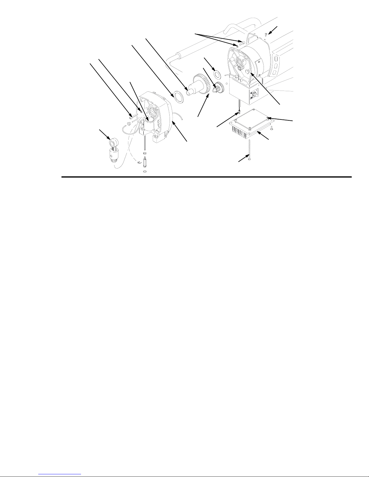
12a
12
TORQUE TO
80 in–lb (9 N.m)
6,5
Note:
not shown
Fig. 28
Filter
19
15
6
12b
16
B
C
11a
47
A
11
56
29
TORQUE TO
80 in–lb (9 N.m)
02995
Page 32

Pressure
WARNING
To
reduce the risk of serious injury
sure Relief Procedure W
fore doing this procedure. Unplug the sprayer!
NOTE:
See Fig. 28 and 29 for this procedure.
arning
, follow the
on page 21 be
Pres-
-
T
ransducer
Guide the harness up through the leg and notch of
3.
the drive housing (1
the connector
While pulling the guide wire out through the bottom
4.
of the motor
housing and motor castings.
1). Secure the guide wire over
.
, guide the harness through the drive
NOTE:
paired or adjusted. If it malfunctions, replace it.
Removal
1.
2.
3.
4.
5.
6.
Installation
The pressure transducer (29) cannot be re
Remove the displacement pump (20). See page
24.
Remove the front cover (13). Remove the screws
(56,75). Lower the motor control card.
Disconnect the harness connector from the motor
control board (47). Remove grommet (77).
Remove the retaining ring (72). Pull the pressure
transducer down and out past the drive housing
(11).
Guide the harness (A) through the motor and drive
housing and remove the pressure transducer
Inspect the spacer (76) and seal (7) for damage.
Replace the seal (7) only if it is cut, nicked, or if
leakage occurred. See page 33.
-
.
5.
Place the grommet (77) over the harness and push
into position in the drive housing hole.
6.
Feed the excess harness cable through the
grommet and fully seat the transducer body into
the hole in the drive housing leg. Secure it with
the retaining ring (72).
7.
Attach the connector to the control board.
Replace the cover(13) and board (47) taking care
not to pinch any wires between the components.
77
A
72
76
7
1.
Using a small piece of solid copper or mild steel
wire (approx. 12”), form a small hook and place it
in the passage of the bottom of the motor
up and out the hole in the drive housing.
2.
Pass a spacer (76) over the harness connector (A)
and down into position at the bottom of the trans
ducer (29).
. Guide it
-
Fig. 29
29
02996
Page 33

Pressure
WARNING
To
reduce the risk of serious injury
sure Relief Procedure W
fore doing this procedure. Unplug the sprayer!
NOTE:
and materials. Replacement of the seal is recom
mended only when leakage has occurred.
Removal
1.
2.
The
PTFE seal is unaf
Remove the displacement pump (20). See page
24.
Using a wooden or plastic probe (such as a tooth
pick), dislodge the packing (7) from its recess in
the manifold (101).
arning
, follow the
on page 21 be
fected by most solvents
Pres-
T
ransducer Seal
2.
Heat the packing (7) in hot water for several
minutes.
Using fingertips or a blunt wooden or plastic probe,
3.
install the packing into the recess. Be careful not
to cause kinks or bends in the packing during
-
-
installation.
Lightly grease or oil the transducer (29) and install
4.
the pump (20). See page 24.
NOTE:
will damage the packing and cause subsequent
leakage.
Excess pressure from the probes or fingernails
7
3.
Remove the packing and clean the manifold
recess with solvent and cloth or cotton swabs.
Inspect for nicks or scratches in the o–ring area.
Installation
1.
Lightly coat the cleaned packing recess in the
manifold with a light grease or oil.
Fig. 30
101
02997
Page 34

Suction
Hose
WARNING
To
reduce the risk of serious injury
sure Relief Procedure W
fore doing this procedure. Unplug the sprayer!
1.
Remove the drain hose (33) from the clip.
2.
Pull upward on the suction hose (32) while un
screwing it from the inlet tube (38). The hose cou
pling (A) threads will engage and the hose will sep
arate from the tube.
3.
Replace the o–ring (27) if it is worn or damaged.
4.
Lubricate the o–ring (27) and the inlet tube (38)
threads with light grease.
5.
Align the suction hose coupling (A) with the
threads of the inlet tube (38). T
onto the tube at least 4 turns to ensure that the
threads have disengaged
swivel joint.
arning
, follow the
on page 21 be
ighten the hose
and can function as a
Pres-
-
-
CAUTION
Misalignment or cross-threading will damage the
parts and/or create shavings which can cause the
o–ring (27) to leak.
LUBRICATE
WITH LIGHT
GREASE.
-
-
Fig. 31
33
32
27
A
38
02998
34 308-319
Page 35

Drain
V
alve
WARNING
To
reduce the risk of serious injury
sure Relief Procedure W
fore doing this procedure. Unplug the sprayer!
1. T
urn the handle (45) to the closed position. Drive
out the pin (44). Remove the handle.
2.
Remove the base (43).
3.
Unscrew the drain valve (42). The gasket (42a)
and seat (42b) will stay in the valve.
42a
42b
APPLY
TORQUE INT
MANIFOLD T
185 in–lb (21 N.m)
Fig.
32
42
O PUMP
O
arning
THREAD SEALANT
42d
42c
HANDLE SHOWN
IN CLOSED POSITION
, follow the
on page 21 be
APPL
T
O F
ACE OF
BASE
44
45
Y GREASE
Pres-
43
-
02819
Repair
1.
Unscrew the spring retainer from the valve body
Remove the spring, washers and stem/ball. Clean
any debris from the ball or seat area.
2.
If replacing the gasket (42a) or seat (42b), pry out
the gasket.
NOTE:
place it with a new one.
1.
2.
NOTE:
valve until the valve is tightened into pump, which cor
rectly seats the gasket.
Whenever the gasket (42a) is removed, re
Coat the o–ring (42d) with grease. Press the stem
(42c) into the valve body
ers and spring retainer into the valve body
Place the seat (42b) in the valve body so the
lapped side is toward the ball. Apply a small
amount of grease to the new gasket (42a) and in
stall it in the valve body
The gasket will protrude from the end of the
. Install the spring, wash
.
-
.
Replacement
1.
Apply a small amount of thread sealant (42e) onto
the valve (42) threads. T
pump manifold to 185 in–lb (21 N.m).
2.
Lightly grease the face of the base (43) and install
the base. T
3.
Securely install the handle (45) and drive the pin
(44).
urn the stem so the pin hole is vertical.
ighten the valve into the
.
-
-
-
308-319 35
Page 36

Model
231–307 & 231–325, Series A
Complete
Sprayer Parts
34
35
13
10
30
32
33
28
15
85
17
18
77
27
38
19
11
6
72
20a
2d
70
25
2e
46
2a
2
86
60
1
22
40
57
66
67
02999
2b
39
4
12b
42d
43
44
11a
59
42c
4a
16
71
73
47
9
12
8
12a
76
29
7
42a
42b
20
36
2c
5
6
56
9
75
45
74
Pressure Control Box
(Bottom V
50
36 308-319
iew)
51
65
49 55
69
64
48
52
54
03020
Page 37

Model
231–307 & 231–325, Series A
Complete
Sprayer Parts
Ref.
No.
Part No.
1 236–523 KIT
2 236–358 KIT
2a 189–490
2b 189–491
2c 187–784
2d 187–791
2e 187–975
4 236–360 KIT, motor
4a 100–069
4b 107–265
4c 107–504
4e 187–784
4f 187–791
4g 187–975
5 101–682 SCREW
6 105–510 LOCKW
7 104–319 P
8 189–270 BRACKET
9 108–865 SCREW
10 100–721
11 236–362 KIT
11a 100–069
12 218–242 CRANKSHAFT
12a 107–434
12b 180–131
13 236–366 KIT
15 218–359
16 218–364
17 176–818
18 176–817
19 103–345 SCREW
20 236–361 KIT
20a 188–663*
21 111–706 SCREW
22 109–570 W
25 111–611 CAP
27 104–938 P
28 162–453
29 236–364 KIT
30 111–602 CLIP
32 187–624
33 187–652
*Not supplied with sprayer
Extra W
arning Labels available free
Description Qty.
, replacement,cart, U–600
, shield, motor
LABEL, ID, Ultra 600
LABEL, ID, Ultra 600
LABEL, DANGER, French
LABEL, DANGER, English
LABEL, W
BALL, thrust
TERMINAL, 3/16” (M) QC,
16 A
TERMINAL, 3/16”, (F), QC,
18 A
LABEL, DANGER, French
LABEL, DANGER, English
LABEL, W
ACKING, o–ring,
PLUG, pipe, 1/4 npt, headless
, housing, drive, U–600
BALL, thrust
BEARING, thrust, front
BEARING, thrust, rear
, cover
CONNECTING, rod assy
GEAR, assy
PIN, straight
SPRING, retaining
, pump, displacement
LABEL, W
ASHER, plain 1/2”
ACKING, o–ring
NIPPLE, 1/4 npt x 1/4 npsm
, transducer, pressure control
HOSE, suction, swivel
HOSE, assy drain
ARNING, elec shock
, electric, DC
WG
WG 1
ARNING, elec shock
, sch, 1/4–20 x .625
ASHER, 1/4 hi–collar
, shield
, panh
, front, U–600
, 2nd stage
, sch, 1/4–20 x 1.25
ARNING 1
, mach, sch, 7/16 x 1.75
, tubing
, spring
, Model 231–325
, U–600
PTFE ) 1
, U–500
Ref.
No.
Part No.
1
34 107–209 SCREW
1
35 189–111
1
36 111–612
1
38 187–627
1
39 235–004
1
40 112–607
1
42 235–014 VAL
1
42a 111–699 GASKET
1
42b 187–615 SEAT
42c 224–968
1
42d 168–110
42e 110–110 SEALANT
43 224–807 VAL
44 111–600
1
45 187–625
1
46 110–997
2
47 236–368 KIT
5
48 186–620
49 110–037 SCREW
1
50 236–354
5
51 108–295
1
52 105–679
1
54 105–658
1
55 105–659 BOOT
1
56 112–381 SCREW
1
57 112–612 CAP
1
59 189–105
1
60 112–400 NUT
1
61 112–373
1
64 236–352
1
1
65 185–565
3
66* 214–701
1
67* 220–955 SPRA
68 206–994
2
69 112–382 NUT
2
70 112–158 GASKET, motor 1
2
71 112–379 SCREW
1
72 112–396
2
73 112–159 GASKET
1
74* 223–541
1
75 112–380 SCREW
1
76 189–269 SP
1
77 189–483 GROMMET
85 235–677 FIL
(see manual 308–249)
86 112–598 SCREW
Description Qty.
, filh, 8–32 x 1.0
LABEL, cover
ADAPTER, tube
TUBE, inlet, swivel
STRAINER, 3/4 unf
WHEEL, semi–pneumatic
VE, drain
, valve, lapped
STEM, drain valve
O–RING, stem
VE, base
PIN, grooved
HANDLE, drain valve
SCREWS, 1/4–20 x .625
, motor control board
LABEL, ground terminal
CORD, power set
BUSHING, strain relief
SWITCH, toggle
RING, locking
, toggle
, hub
HOUSING, junction box
, self–retaining
KNOB, pressure adjustment
POTENTIOMETER, pressure
adjustment 1
LABEL, knob
HOSE, whip, 3/16” x 3’
Y GUN, contractor
LIQUID, throat seal (not shown)
, shaft sealing
RING, external retaining
HOSE, 1/4” x 50’
ACER, transducer
TER, fluid
, front
, seat valve
, pipe (not shown)
, mach, pnh, 10–24 x .500
, panh, 10–24 x 3.5
, filh, 10–24 x 0.75
, heatsink
, panh, 8–32 x 0.5
, cable
, trusshead, 8–32
4
1
1
1
1
2
1
1
1
1
1
1
1
1
1
2
1
1
1
1
1
1
1
1
2
2
1
2
1
1
1
1
1
1
2
1
1
1
2
1
1
1
2
308-319 37
Page 38

Displacement
Pump Parts
Model 236–361 Series A
Ref
No. Part
101 236–365
102
103 176–757* GLAND,
104 176–997* V–PACKING,
105 176–755* V–PACKING,
106 176–754* GLAND,
107 235–709 DISPLACEMENT
108 218–197 PIST
109 105–444*
110 176–751 NUT,
111 176–750* GLAND,
112 176–882* V–PACKING,
113 176–749* V–PACKING,
114 180–073* GLAND,
115 235–708 CYLINDER,
116 108–526* P
117 187–614 NUT,
118 224–966 INLET
119 111–603* PACKING,
120 176–760 GUIDE,
121 105–445* BALL,
122 176–759* PIN,
123 180–656 PLUG
124 102–969* SEALANT 1
125 105–522* PACKING,
126 186–652* WASHER,
127 104–319 PACKING,
*Supplied
Keep a repair kit on hand to reduce
down time.
No.
Description Qty
MANIFOLD,
176–758
P
ACKING NUT
BALL,
ACKING,
in Repair Kit 235–703
pump 1
female, throat
plastic, throat
leather,
throat
male.
throat
ROD
ON,
valve 1
5/16”,
piston
hex, 1/2–20 unf–2b
male,
piston
plastic,
piston
leather,
piston
female,
piston
pump 1
o–ring,
PTFE
jam,1-3/8
V
1/2”, inlet
ball stop
18 unef–2
ALVE 1
o–ring, PTFE
ball
u-cup, polyurethane
backup,
o–ring,
steel
manifold
1
b1
1
123
102
1
1
3
2
103*
107
1
1
*105
1
1
1
104*
3
2
127
1
101
106*
*113
109*
110
111*
112*
1
1
1
1
114*
1
1
117
125*
126*
108
*116
115
120
*122
121*
119*
118
03149
Page 39

Technical
Power
Requirements
Generator
Working
Motor 3/4
Cycles/Gallon (liter) 530 (140).
Delivery 0.55 gpm (2.1 lpm).
Tip
Size
Power Cord
.
. . . . . . . . . . . . . . . . . . . .
Pressure Range
.
. . . . . . . . . . . . . . . . . . . . . . . . . . . . . . . . . . .
. . . . . . . . . . . . . . . . . . . . . . .
.
. . . . . . . . . . . . . . . . . .
.
. . . . . . . .
.
. . . . . . . . . . . . .
1
phase, 15 amp minimum
0–2750 psi (0 – 195 bar)
.
. . .
. . . . . . . . . . . . . . . . . . . . .
one gun to 0.025 new tip
with
latex at 2000 psi (138 bar)
No. 14 A
120 V
AC, 60Hz,
3000 W
WG, 3 wire, 6’ (1.8 m)
att minimum
Dimensions
HP
Data
Inlet
Paint Strainer
Outlet Filter
Pump
Fluid
Outlet Size
Wetted
Displacement Pump
Filter
NOTE:
.
. . . . . . . . . . . . . . . . .
Inlet Size
Parts:
Aluminum, Polyethylene, Delrin, Leather
.
. . . .
D
Aluminum, Steel,
.
. . . . . . . . . .
Stainless
. . . . . . . . . . . . . . . . . . . . . . . .
.
. . . . . . . . . . . . . . . . . . . . . . .
.
.
is a
12 mesh (1525 micron)
Steel Screen, reusable
60 mesh (250 micron)
1/2 npt(f).
1/4 npsm
Stainless steel, Carbon steel,
PTFE,)Stainless steel
Weight
Height 21 in (533 mm).
Length 22 in (559 mm).
Width 15 in (381 mm).
(dry w/o packaging)
. . . . . . . . . . . . . . . . . . . . . . . . . . .
. . . . . . . . . . . . . . . . . . . . . . . . . . .
. . . . . . . . . . . . . . . . . . . . . . . . . . . .
.
. . . . . . . . . . .
50 lb (23 kg)
Accessories
DANGER
The English language DANGER label shown on page 1
is also on your sprayer. If you have painters who do not
read
your sprayer. The drawing below shows the best placement
Order the labels directly from Graco, free of charge:
1–800–328–0211
French 187–784
Spanish 185–956
German 185–961
Greek 186–041
Korean 186–045
English 187–791
LABELS
English, order one of the following labels to apply to
of these labels for good visibility
Apply
language here
.
other
Page 40

The
WARRANTY
Graco
the date of sale
warranty
defective, with the exception of defects in parts on the drive train/gear box, which will be repaired or replaced for forty-eight
months from the date of sale and the electric motor (excluding brush replacement, which is routine maintenance) or pressure
control assembly which will be repaired or replaced for twenty-four months from the date of sale. This warranty applies only when
the equipment is installed, operated and maintained in accordance with Graco’
This warranty does not cover
misapplication, abrasion, corrosion, inadequate or improper maintenance, negligence, accident, tampering, or substitution of
non–Graco component parts. Nor shall Graco be liable for malfunction, damage or wear caused by the incompatibility with Graco
equipment of structures, accessories, equipment or materials not supplied by Graco, or the improper design, manufacture, instal
lation, operation or maintenance of structures, accessories, equipment or materials not supplied by Graco.
This warranty is conditioned upon the prepaid return of the equipment claimed to be defective to an authorized Graco distributor
for verification of the claim. If the claimed defect is verified, Graco will repair or replace free of charge any defective parts. The
equipment will be returned to the original purchaser transportation prepaid. If inspection of the equipment does not disclose any
defect in material or workmanship, repairs will be made at a reasonable charge, which charges may include the costs of parts,
labor and transportation.
DISCLAIMERS AND LIMITATIONS
The terms of this warranty constitute purchaser’s sole and exclusive remedy and are in lieu of any other warranties (express or
implied),
liabilities, including product liabilities, based on negligence or strict liability
tial damages or loss is expressly excluded and denied. In no case shall Graco’
Any action for breach of warranty must be brought within two (2) years of the date of sale.
Graco Ultra
warrants all equipment manufactured by it and bearing its name to be free from defects in material and workmanship on
by an authorized Graco distributor to the original purchaser for use. As purchaser’s sole remedy for breach of this
, Graco will, for a period of twelve months from the date of sale, repair or replace any part of the Ultra equipment proven
, and Graco shall not be liable for
including warranty of merchantability or warranty of fitness for a particular purpose,
Warranty
, any malfunction, damage or wear caused by faulty installation,
. Every form of liability for direct, special or consequen
and Disclaimers
s written recommendations.
and of any non–contractual
s liability exceed the amount of the purchase price.
-
-
EQUIPMENT NOT COVERED BY GRACO WARRANTY
Graco makes no warranty
respect to accessories, equipment, materials, or components sold but not manufactured by Graco. These items sold, but not
manufactured by Graco (such as electric motor
Graco will provide purchaser with reasonable assistance in making any claim for breach of these warranties.
, and disclaims all implied
Phone
TO PLACE AN ORDER
or call this number to identify the distributor closest to
you:
1–800–367–4023 T
, contact your Gracodistributor,
oll Free
warranties of merchantability and fitness for a particular purpose,
, switches, hose, etc.) are subject to the warranty
, if any
, of their manufacturer
Numbers
FOR TECHNICAL ASSISTANCE
mation
or assistance regarding the application of equip
ment:
1–800–543–0339 T
oll Free
, service repair infor-
with
.
-
Sales
Foreign Offices:
Offices:
GRACO
Atlanta, Chicago, Dallas, Detroit, Los Angeles, Mt. Arlington (N.J.)
Canada; England; Korea; Switzerland; France; Germany; Hong Kong; Japan
INC.P.O. BOX 1441
PRINTED
MINNEAPOLIS, MN
IN U.S.A. 308–319 2/94
55440–1441
 Loading...