

Graco 231-008 A Series, 231433 B Series, ULTRA 433, 231-008, 231433 Instructions For Use Manual
Page 1
INSTRUCTIONS/FIELD REPAIR G =7-w7
OAACO
Rev E
SUPERSEDES D
This manual contains IMPORTANT
WARNINGS and INSTRUCTIONS
READ AND RETAIN FOR REFERENCE
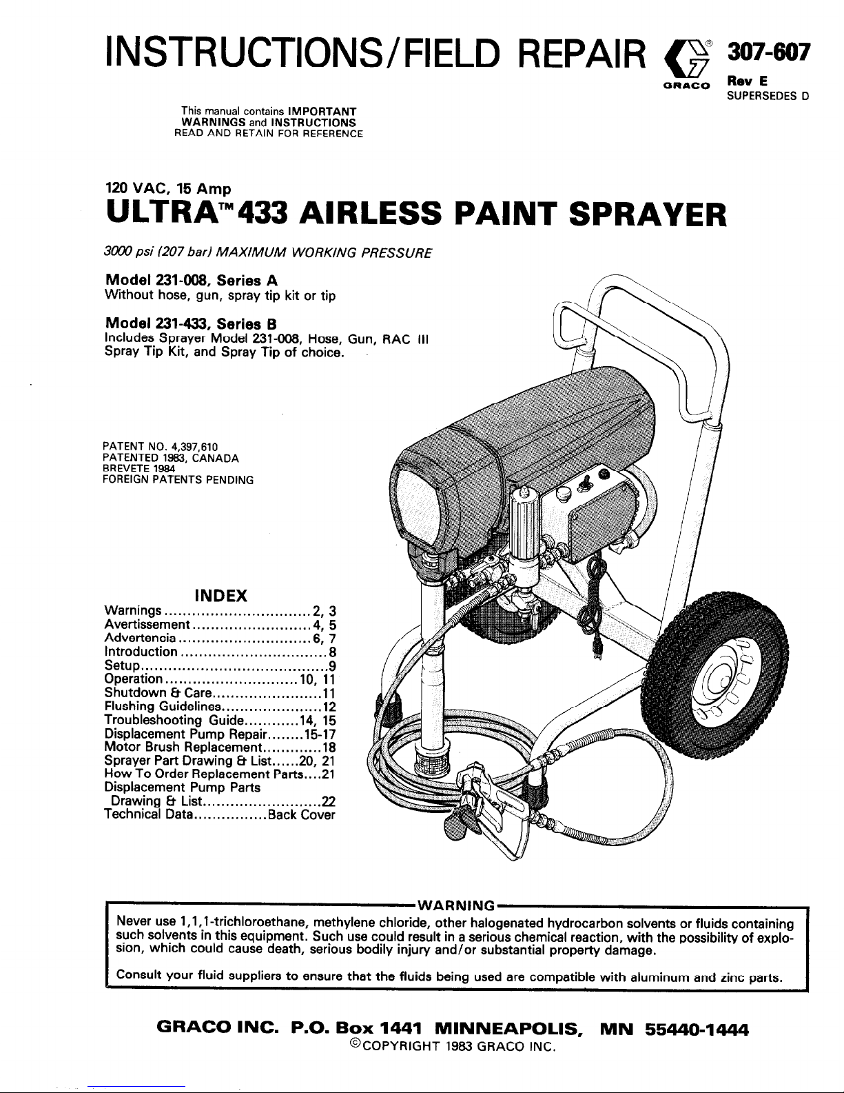
120 VAC, 15 Amp
ULTRA’“433 AIRLESS PAINT SPRAYER
3ooO psi (207 bad MAXIMUM WORKING PRESSURE
Model 231-008, Series A
Without hose, gun, spray tip kit or tip
Model 231433, Series 6
Includes Sprayer Model 231-008, Hose, Gun, RAC III
Spray Tip Kit, and Spray Tip of choice.
PATENT NO. 4,397,610
PATENTED 1963, CANADA
BREVETE 1964
FOREIGN PATENTS PENDING
INDEX
Warnings.. .............................
.2, 3
Avertissement
.........................
.4, 5
Advertencia
............................
.6, 7
Introduction ...............................
.8
Setup..
......................................
.9
Operation..
...........................
10,
11
Shutdown 8 Care
.......................
.ll
Flushing Guidelines..
...................
.12
Troubleshooting
Guide.. .........
.14,
15
Displacement Pump Repair........lB17
Motor Brush Replacement
............ .18
Sprayer Part Drawing 8 List..
... .20, 21
How To Order Replacement Parts..
. .21
Displacement Pump Parts
Drawing Et List.. .......................
.22
Technical Data ...............
.Back Cover
WARNING
Never use l,l, 1 -trichloroethane, methylene chloride, other halogenated hydrocarbon solvents or fluids containing
such solvents in this equipment. Such use could result in a serious chemical reaction, with the possibility of explosion, which could cause death, serious bodily injury and/or substantial property damage.
Consult your fluid suppliers to ensure that the fluids being used are compatible with aluminum and zinc parts.
GRACO INC. P.O. Box 1441 MINNEAPOLIS, MN 55440-1444
@COPYRIGHT 1983 GRACO INC.
Page 2
WARNING
HIGH PRESSURE SPRAY CAN CAUSE SERIOUS INJURY.
FOR PROFESSIONAL USE ONLY. OBSERVE ALL WARNINGS.
Read and understand all instruction manuals before operating equipment.
FLUID INJECTION HAZARD
General Safetv
This equipment generates very high fluid pressure. Spray from
the gun, leaks or ruptured components can inject fluid
through your skin and into your body and cause extremely
serious bodily injury, including the need for amputation. Also,
fluid injected or splashed into the eyes can cause serious
damage.
NEVER point the spray gun at anyone or at any part of the
body. NEVER put hand or fingers over the spray tip. NEVER
try to “blow back” paint; this is NOT an air spray system.
Spray Gun Safety Devices
Se sure all gun safety devices are operating properly before
each use. Do not remove or modify any part of the gun; this
can cause a malfunction and result in serious bodily injury.
Safety Latch
Whenever you stop spraying, even for a moment, always set
the gun safety latch in the closed or “safe” position, making
the gun inoperative. Failure to set the safety latch can result in
accidental triggering of the gun.
Diffuser
ALWAYS have the tip guard in place on the spray gun when
spraying.
The gun diffuser breaks up spray and reduces the risk of injec-
tion when the tip is not installed. Check diffuser operation
ALWAYS follow the Pressure Relief Procedure, below,
before cleaning or removing the spray tip or servicing any
system equipment.
NEVER try to stop or deflect leaks with your hand or body.
regularly.
Follow the Pressure Relief Procedure,
below,
then remove the spray tip. Aim the gun into a metal pail,
holding the gun firmly to the pail. Using the lowest possible
pressure, trigger the gun. If the fluid emitted is not diffused into an irregular stream, replace
the
diffuser immediately.
Be sure equipment safety devices are operating properly
before each use.
Medical Treatment
If any fluid appears to penetrate your skin, get
EMERGENCY MEDICAL CARE AT ONCE.
DO NOT TREAT AS A SIMPLE CUT.
Tell the doctor exactly what fluid was injected. For treatment
instructions, have your doctor call the
NATIONAL POISON CENTER NETWORK
(4121661-6666
Tip Guard
ALWAYS have the tip guard in place on the spray gun while
spraying. The tip guard alerts you to the injection hazard and
helps prevent accidentally placing your fingers or any part of
your body close to the spray tip.
Spray i‘ip Safety
Use extreme caution when cleaning or changing spray tips. If
the spray tip clogs while spraying, engage the gun safety latch
immediately. ALWAYS follow the Pressure Relief Procedure and then remove the spray tip to clean it.
NEVER wipe off build up around the spray tip until pressure is
fully relieved and the gun safety latch is engaged.
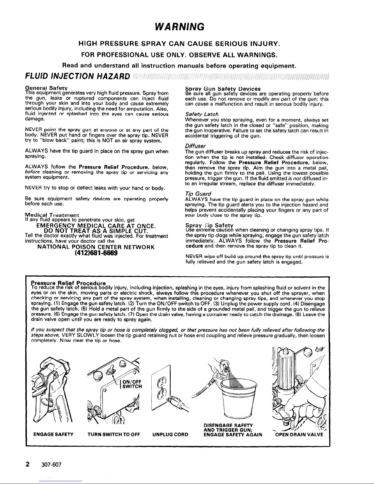
Pressure
Relief Procedure
To reduce the risk of serious bodily injury, including injection, splashing in the eyes, injury from splashing fluid or solvent in the
eyes or on the skin, moving parts or electric shock, always follow this procedure whenever you shut off the sprayer, when
checking or servicing any part of the spray system, when installing, cleaning or changing spray tips, and whenever you stop
spraying. (1) Engage the gun safety latch. (2) Turn the ON/OFF switch to OFF. (3) Unplug the power supply cord. (4) Disengage
the gun safety latch. (5) Hold a metal part of the gun firmly to the side of a grounded metal pail, and trigger the gun to relieve
pressure. (6) Engage the gun safety latch. 17) Open the drain valve, having a container ready to catch the drainage. (8) Leave the
drain valve open until you are ready to spray again.
If you suspect that the spray tip or hose is completely clogged, or that pressure has not been fully relieved after following the
steps above, VERY SLOWLY loosen the tip guard retaining nut or hose end coupling and relieve pressure gradually, then loosen
completely. Now clear the tip or hose.
TURN SWITCH TO OFF
DISENGAGE SAFETY
AND TRIGGER GUN;
ENGAGE SAFETY AGAIN
OPEN DRAIN VALVE
2
307-607
Page 3
EQUIPMENT MISUSE HAZAF?D
General Safety
Any misuse of the spray equipment or accessories, such as
overpressurizing, modifying parts, using incompatible
chemicals and materials, or using worn or damaged parts, can
cause them to rupture and result in injection or other serious
bodily injury, fire, explosion or property damage.
NEVER alter or modify any part of this equipment; doing so
could cause it to malfunction.
CHECK all spray equipment regularly and repair or replace
worn or damaged parts immediately.
System Pressure
This sprayer can develop 3&N psi (207 bar) MAXIMUM
WORKING PRESSURE. Be sure that all spray equipment and
accessories are rated to withstand the maximum working
pressure of this sprayer. DO NOT exceed the maximum working pressure of any component or accessory used in the
system.
Fluid Compatibility
BE SURE that all fluids and solvents used are chemically compatible with the wetted Darts shown in the Technical Data on
ihe back cover. Always’ read the fluid and solvent manufacturer’s literature before using them in this sprayer.
HOSE SAFETY
High pressure fluid in the hoses can be very dangerous. If the
hose develops a pinhole leak, split or rupture due to any kind
of wear, damage or misuse, the high pressure spray emitted
from it can cause an injection injury or other serious bodily in-
jury or property damage.
ALL FLUID HOSES MUST HAVE SPRING GUARDS!
The
spring guards help protect the hose from kinks or bends at or
close to the coupling which can result in hose rupture.
TIGHTEN all fluid connections securely before each use. High
pressure fluid can dislodge a loose coupling or allow high
pressure spray to be emitted from the coupling.
NEVER use a damaged hose. Before each use, check entire
hose for cuts, leaks, abrasion, bulging cover, or damage or
movement of the hose couplings. If any of these conditions
exist, replace the hose immediately. DO NOT try to recouple
high pressure hose or mend it with tape or any other device. A
repaired hose cannot contain the high pressure fluid.
HANDLE AND ROUTE HOSES CAREFULLY. Do not pull on
hoses to move equipment. Do not use fluids or solvents which
are not compatibiewith the inner tube and cover of the hose.
DO NOT exoose Grace hose to temperatures above 160°F
W”C) or beiow -40°F WOW.
Hose Groundin Continuity
Proper hose groun mg continuity is essential to maintaining a !-
grounded spray system. Check the electrical resistance of your
air and fluid hoses at least once a week. If your hose does not
have a tag on it which specifies the maximum electrical
resistance, contact the hose supplier or manufacturer for the
maximum resistance limits. Use a resistance meter in the appropriate range for your hose to check the resistance. If the
resistance exceeds the recommended limits, replace it immediately. An ungrounded or poorly grounded hose can make
your system hazardous. Also read
FIRE OR EXPLOSION
HAZARD.
FIRE OR EXPLOSlON HAZARD
Static electricity is created by the high velocity flow of fluid
through the pump and hose. If every part of the spray equip-
ment is not properly grounded, sparking may occur, and the
system may become hazardous. Sparking may also occur
when plugging in or unplugging a power supply cord. Sparks
can ignite fumes from solvents and the fluid being sprayed,
dust particles and other flammable substances, whether you
are spraying indoors or outdoors, and can cause a fire or ex-
plosion and serious bodily injury and property damage.
Always plug the sprayer into an outlet at least 20 feet (6 m)
away from the sprayer and the spray area. Do not plug in or
unplug any power supply cords in the spray area when there is
any chance of igniting fumes still in the air.
If you experience any static sparking or even a slight shock
while using this equipment,
STOP SPRAYING IMMEDI-
ATELY.
Check the entire system for positive grounding. Do
not use the system again until the problem has been identified
and corrected.
Groundinit . To reduce t e nsk of static sparking, ground the sprayer and
all other spray equipment used or located in the spray area.
CHECK your local electrical code for detailed grounding instructions for your area and type of equipment. BE SURE to
ground all of this spray equipment:
1.
2.
3.
4.
5.
6.
Sprayer: plug the power supply cord, or extension cord,
each equipped with an undamaged three-prong plug, into
a properly grounded outlet. Do not use an adapter. All extension cords must have three wires and be rated for 15
amps.
Fluid hoses: use only grounded hoses with a maximum of
500 feet (150 m) combined hose length to ensure grounding continuity. Refer to
Hose Grounding Continuity.
Spray gun: obtain grounding through connection to a
properly grounded fluid hose and sprayer.
Object being sprayed: according to local code.
All solvent pails used when flushing, according to local
code. Use only metalpails, which are conductive. Do not
place the pail on a non-conductive surface, such as paper
or cardboard, which interrupts the grounding continuity.
To maintain grounding continuity when flushing or relieving pressure, always hold a metal part of the gun firmly to
the side of a grounded metal pail, then trigger the gun.
MOVUVG
PARTS
HAZARD
Moving parts can pinch or amputate your fingers or other
body parts. KEEP CLEAR of moving parts when starting or
operating the sprayer. Unplug the sprayer and relieve pressure
before checking or servicing the sprayer to prevent it from
starting accidentally.
iMPORTANT
United States Government safety standards have been adopted under the Occupational Safety and Health Act. These standards-particularly the General Standards, Part 1910, and the Construction Standards, Part 1926-should be consulted.
307-607
3
Page 4
A VERTISSEMENT
La
pulwkisation A haute pression peut causer des blessures trk graves.
RBserv6 exclusivement ZI I’usage professionnet. Observer toutes les consignes de s6curit6.
Bien lire et bien comprendre tous les manuels d’instructions avant d’utiliser le mat&iel.
RISQUES D’INJECTION
Consignes g&n&ales de sbcurit6
Cet
appareil produit un fluide & tr&s haute pression. Le fluide
pulvkris~ par le pistolet ou le fluide sous pression provenant de
fuites ou de ruptures peut p&&rer sous la peau ou a I’intkrieur
du corps et entrainer des blessures trk graves, voir mbme une
amputation. MBme sans &re sous pression, le fluide Bclaboussant ou entrant dans les yeux peut aussi entrainer des
blessures graves.
enlever ni modifier une partie quelconque du pistolet; ceci risquerait d’entrainer un mauvais fonctionnement et des
blessures graves.
Verrou de s&wit6
NE JAMAIS pointer le pistolet vers quelqu’un ou vers une partie quelconque du corps. NE JAMAIS mettre la main ou les
doigts sur I’ajutage du pulvkrisateur. NE JAMAIS essayer de
“refouler” la peinture. Cet appareil N’est PAS un compresseur
pneumatique.
A chaque fois que I’on s’arrbte de pulkiser, meme s’il s’agit
d’un court instant, toujours mettre le verrou de skuritk du
pistolet sur la position “fermbe” ou “sf+curiW’ (“safe”) pour
empkher le pistolet de fonctionner. Si le verrou de skcuritk
n’est pas mis, le pistolet peut se dkclencher accidentellement.
Diffuser
TOUJOURS garder la protection de I’ajutage en place sur le
pistolet pendant la pulwkisation.
TOUJOURS observer la
March g Suivre pour DBtendre la
Pression
don&e plus loin,
avant
de nettoyer ou d’enlever
I’ajutage du pulv&isateur, ou d’effectuer un travail quelconque sur une partie de I’appareil.
NE JAMAIS essayer d’arrbter ou de dbvier les fuites avec la
main ou le corps.
Avant chaque utilisation, bien s’assurer que les dispositifs de
skuritb fonctionnent correctement.
Soins m6d:caux
En cas de p&&ration de fluide sous la peau:
DEMANDER IMMEDIATEMENT DES SOINS
MEDICAUX D’URGENCE.
NE PAS SOIGNER CEl-fE BLESSURE COMME
UNE SIMPLE COUPURE.
Dire exactement au mkdecin quel type de liquide a BtB inject&
Pour avoir des instructions concernant le traitement approprib, dire au mBdecin d’appeler le
iENTRE ANTI-POISON SUIVANT:
NATIONAL POISON CENTER NETWORK
Le diffuseur du pistolet sert B diviser le jet et g rbduire les risques d’injection accidentelle quand I’ajutage n’est pas en
place. VBrifier le fonctionnement du diffuseur rkguli&ement.
Pour cette vbrification, detendre la pression en observant la
Marche B Suivre pour DBtendre la Pression
don&e plus
loin puis enlever I’ajutage du pulv&isateur. Pointer le pistolet
dans un seau en m&al, en le maintenant fermement contre le
seau. Puis, en utilisant la pression la plus faible possible, appuyer sur la gachette du pistolet. Si le fluide projet n’est pas
diffuse sous forme de jet irrbgulier, remplacer immkdiatement
le diffuseur.
Protection de
I’ajutage
TOUJOURS maintenir la protection de I’ajutage en place sur le
pistolet du pulvkrisateur pendant la pulv&isation. La protection de I’ajutage attire I’attention sur les risques d’injection et
contribue ?I Bviter que les doigts ou une partie quelconque du
corps ne passe accidentellement B proximitb immediate de
I’ajutage du pulvkrisateur.
(4121681-6669
Dispositifs de stkuritb du pistolet
Avant chaque utilisation, bien s’assure que tous les dispositifs
de skuritb du pistolet fonctionnent correctement. Ne pas
Consignes de sbcuritb concernant I’ajutage du
pulvcksateur
Faire extrsmement attention 8 I’occaslon du nettoyage ou du
remplacement des ajutages du pulvtkisateur. Si I’ajutage se
bouche pendant la pulwkisation, mettre immediatement le
verrou de skuritt+ du oistolet. TOUJOURS bien observer la
Marche B Suivre pour Dbtendre la Pression
puis enlever
I’ajutage du pulvkisateur pour le nettoyer.
NE JAMAIS essuyer ce qui s’est accumulk autour de I’ajutage
du pulvrkisateur avant que la pression ne soit compktement
t,,mh&, ,a+ n,,~ le \,~rrn, I rim dr.,,ritd ,-I,, nictnlnt no rnit nnncw~d,
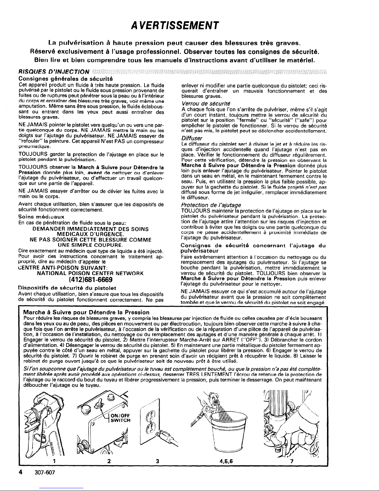
Marche
d Suivre pour Dbtendre la Pression
Pour reduire les risques de blessures graves, y compris les blessures par injection de fluide ou celles causbes par d’kla boussant
dans les yeux ou au de peau, des pi&es en mouvement ou par Electrocution, toujours bien observer cette marche B suivre B chaque fois que I’on
arr6te
le
pulvbrisateur,
B I’occasion de la vckification ou de la reparation d’une pike de I’appareil de pulv&isa-
tion, g I’occasion de I’installation, du nettoyage ou du remplacement des ajutages et d’une man&e gemkale B chaque arrbt. 1)
Engager le verrou de skuritb du pistolet. 2) Mettre I’interrupteur Marche-Arr& sur ARRET (“OFF”). 3) DBbrancher le cordon
d’alimentation. 4) Dkengager le verrou de skuritb du pistolet. 5) En maintenant une partie m&allique du pistolet fermement appuyke contre le cBtk d’un seau en m&al, appuyer sur la gachette du pistolet pour lib&er la pression. 6) Engager le verrou de
dcuritb du pistolet. 7) Ouvrir le robinet de purge en prenant soin d’avoir un recipient p& 8 rkupker le liquide. 81 Laisser le
robinet de purge ouvert jusqu’8 ce que le pulwkisateur soit de nouveau prdt B etre utilis6.
Sil’on soupconne que
rajutage du putvkisateur ou le tuvau est compktement boucht5, ou que la pression n’a pas Bt.4 compl&tement lib&&e aprtk avoir proc8d4 aux op&ations ci-dessus, desserrer TRES LENTEMENT l’krou de retenue de la protection de
I’ajutage ou le raccord du bout du tuyau et libkrer progressivement la pression, puis terminer le desserrage. On peut maiAtenant
dbboucher I’ajutage ou le tuyau.
1
2
3
4.5.6
7
Page 5
RISQUES EN CAS DE MAUVAISE UTILISATION DU MATERIEL
Consignes gbn6rales de s6curit6
Toute utilisation anormale de I’appareil de pulwkisation ou des
accessoires comme, par exemple, la mise sous une pression
excessive, les modifications de pikes, I’utilisation de produits
chimiques et de mati&res incompatibles et I’utilisation de
pikes us&es ou abimbes peut causer des degbts B I’appareil ou
des ruptures de pikes et entrainer une injection de liquide ou
d’autres blessures skrieuses, un incendie, une explosion ou
d’autres d6g&s.
NE JAMAIS alt&er ou modifier une piike de cet appareil; ceci
risquerait d’entrainer son mauvais fonctionnement.
VERIFIER rbguli&ement tout I’appareil de pulv&isation et ses
Bquipements et r&parer ou remplacer immbdiatement les
pikes u&es ou abimkes.
Ce pulwkisateur peut produire une PRESSIONMAXIMUM DE
TRAVAIL 207 bar (3ooO lb/po.2). S’assurer que tous les
Blkments du pulwkisateur et ses accessoires sont concus pour
resister 8 la pression maximum de travail de ce pulvtkisateur.
NE PAS dbpasser la pression maximum de travail d’aucun des
Blbments ou accessoires utilis& avec cet appareil.
Compatibilit6 chimique des corps
BIEN S’ASSURER aue tous les cores des solvants utili&s
sont chimiquement cbmpatibles avec’les parties mouilkes indiqubes dans les “Donnkes techniques”, au dos de la couverture. Toujours lire soigneusement les documents et brochures
du fabricant des fluides et solvants utilisks avant de s’en servir
dans ce pukkisateur.
MESURES DE SECURITE CONCERNANT LES TUYAUX FLEXIBLES
Le fluide ZI haute pression circulant dans les tuyaux peut btre
trk dangereux. En cas de fuite sur le tuyau, m6me minuscule,
de fissure, dkhirure ou rupture g la suite de I’usure, de dkgdts
ou d’une mauvaise utilisation, les projections de fluide haute
pression qui en proviennent peuvent entrainer des blessures
graves par p&&ration sous la peau ou par contact, ainsi que
des dbgdts matkriels.
TOUS LES TUYAUX FLEXIBLES DOIVENT AVOIR DES
RESSORTS SPIRALE DE PROTECTION!
Les spirales de
protection contribuent B bviter la formation de pliures, de
boucles ou de noeuds sur les tuyaux qui pourraient entrainer la
rupture du tuyau & I’endroit du raccord ou ?I son voisinagk
SERRER FERMEMENT tous les raccords avant chaque utilisation. Le fluide sous pression peut faire sauter un raccord
desserrb ou produire un jet g haute pression s’khappant par le
raccord.
NE JAMAIS utiliser un tuyau endommagk. Avant chaque
utilisation, verifier entierement chaque tuyau pour dkeler les
coupures, fuites, abrasions, boursouflures de I’enveloppe ou
toute autre d&&ioration ou jeu des raccords. Si I’on constate
l’une de ces d&&iorations, il faut remplacer le tuyau im-
mkdiatement. NE PAS essayer de refaire le raccord d’un tuyau
haute pression ni de rbparer le tuyau avec du ruban adhkif ou
RISQUES D’INCENDIE OU D’EXPLOSION
De 1’6lectricitk statique est produite par le passage du fluide B
grande vitesse dans la pompe et dans les tuyaux. Si toutes les
pieces de I’appareil de pulwkisation ne sont pas convenablement relibes g la masse ou B la terre, des Btincelles peuvent se
produire et I’appareil risque d’btre dangereux. Des Btincelles
peuvent Bgalement se produire B I’occasion du branchement
ou du dkbranchement du cordon d’alimentation. Les Btincelles
sont suffisantes pour allumer les vapeurs de solvants et le
fluide pulv&is& les fines particules de poussi&re ainsi que
d’autres substances inflammables, quand on pulkrise ?I I’interieur ou B I’extkieur, et elles peuvent causer un incendie ou
une explosion, ainsi que des blessures graves et des d6gits
matbriels. Toujours brancher le pulv&isateur dans une prise se
trouvant B au moins 6 m (20 pieds) de I’appareil et de I’endroit
oti se fait la pulvkrisation. Ne pas brancher ou debrancher un
cordon d’alimentation quel qu’il soit dans la zone oti se fait la
pulwkisation quand il y a le moindre risque que des vapeurs
encore prtkentes dans I’air prennent feu.
Mise B la terre ou A la masse
Pour rbduire les risques de production d’&incelles d’blectricitb
statique, le pulvtkisateur et tous les Bquipements utilisks ou se
trouvant dans la zone de pulvkrisation doivent dtre relik B la
terre ou B la masse. Pour connaitre le d&ail des instructions de
mise ?I la terre dans la r&ion et le type particulier d’bquipe-
ment, CONSULTER le co& ou les regkm&tations Blectriqies
locales. S’ASSURER aue tous les Bauipements de pulv&isation suivants sont bien’ relik a la terrk:
1. Pulvhrisafeur: Brancher le cordon d’alimentation ou la
rallonge qui doivent &re Bquipes d’une prise g 3 fiches en bon
&at, dans une prise de courant convenablement mise a la
terre. Ne pas utiliser d’adaptateur. Toutes les rallonges doivent
avoir 3 fils et btre prevues pour 15 amp&es.
par tout autre moyen. Un tuyau repare ne peut pas r&sister au
fluide sous pression.
MANIPULER LES TUYAUX AVEC PRECAUTION ET
CHOISIR SOIGNEUSEMENT LEUR CHEMIN. Ne pas dbplacer
le fluide en tirant sur le tuyau. Ne pas utiliser de fluides ou de
solvants qui ne sont pas compatibles avec I’enveloppe intkrieure ou extkrieure du tuyau. NE PAS exposer le tuyau 3
des temperatures supkrieures B 82°C (18O’F) ou infbrieures a
-WC (-40°F).
Continuit6 de la mise B la terre des tu
aux
Une bonne continuitb de la mise B la terre es tuyaux est cr
essentielle pour maintenir la mise a la terre de I’ensemble de
vaporisation. VBrifiez la ksistance Blectrique de vos tuyaux B
fluides et a air, au moins une fois par semaine. Si votre tuyau
ne comporte pas d’btiquette qui precise la resistance Blectrique maximum, prenez contact avec le fournisseur de tuyaux
ou la fabricant pour avoir les limites de kistance maximum.
Utilisez un m&tre de resistance de la gamme appropribe pour
votre tuyau et v&ifiez la rbsistance. Si celle-ci dbpasse les
limites recommand4es. remplacez le tuyau immbdiatement.
Un tuyau sans mise B la terre ou avec une mise B la terre incorrecte peut entrainer des risques pour votre syst&me. Lisez
aussi
LES RISQUES D’INCENDIE OU D’EXPLOSION
ci-
dessus.
2. Tuyaux flexibles: Afin d’assurer la continuitk de la mise B la
terre, n’utiliser que des tuyaux comportant une mise B la terre
et avant une longueur maximum combinbe de 150 m
(1500 pieds). Se reporter Bgalement au paragraphe “Con-
tinuit6 du circuit de mise B la terre des tuyaux”.
3. Pisfolef: RBaliser la mise B la terre en le raccordant 8 un
tuyau flexible et g un pulverisateur dbjja convenablement relies
B la terre.
4. Objets, matkiel ou surfaces recevant la pulvhrisation:
observer le code ou les reglementations locales.
5. Tous /es seaux de solvants utilik pour le rincage: observer
le code ou les rkglementations locales. N’utiliser que des seaux
mhtalliques conducteurs de 1’6lectricite. Ne pas mettre le seau
sur une surface non conductrice comme sur du papier ou du
carton car cela interromprait la continuitb le la mise 2 la terre.
6. Pour conserver la continuith de la mise B la terre quand on
rince le mathriel ou quand on lib&e la pression, toujours
maintenir une partie m&allique du pistolet fermement appuybe
contre le c8tB d’un seau en m&al puis appuyer sur la detente
du pistolet.
Mesures de Sbcurit6 concernant le Rincage
Pour rbduire les risaues de blessures par p&&ration de la
peau et les risques d& aux Btincelles d’8leciricit6 statique ou
aux Bclaboussures, observer la marche a suivre pour le rincage
don&e a la page 12 de ce manuel. Observer la
“Marche A
Suivre pour DBtendre la Pression”
donnbe a la page 4 en
enlever l’ajutage du pulvhrisateur avant le rincage. Maintenir
une partie m&allique du pistolet fermement appuybe contre le
c&t! d’un seau en m&a/ et utiliser la pression la plus faible
possible pendant le rincage.
307-607 5
Page 6
ADVERTENCIA
EL ROCIADO A ALTA PRESION PUEDE CAUSAR GRAVES LESIONES.
SOLO PARA US0 PROFESIONAL. RESPETE LOS AVISOS DE ADVERTENCIA.
Lea y entienda todo el manual de instrucciones antes de manejar el equipo.
PELlGRO DE INYECClON DE FLUID0
Seguridad general
Este equip0 genera un fluid0 a una presion muy alta. El
rociado de la pistola, 10s escapes de fluid0 o roturas de 10s
componentes pueden inyectar fluid0 en la piel y el cuerpo y
causar lesiones extremadamente graves, incluyendo a veces la
necesidad de amputation. TambiBn, el fluid0 inyectado o
salpicado en 10s ojos puede causar graves daiios.
NUNCA apuntar la pistola hacia alguien o alguna parte del
cuerpo. NUNCA colocar la mano o 10s dedos encima de la boquilla. NUNCA tratar de “hater retornar la pintura”; este NO
es un sistema de rociado de aire.
SIEMPRE tener colocado el protector de la boquilla en la
pistola mientras se esta pulverizando.
SIEMPRE seguir el
procedimiento de descarga de presih,
dado m& abjo, antes de limpiar o sacar
la
boquilla o de dar
servicio a cualiquier equip0 del sistema.
NUNCA tratar de parar o desviar 10s escapes con la mano o el
cuerpo.
Asegurar que todos 10s aparatos de seguridad del equip0
estan funcionando bien antes de cada uso.
Tratamiento medico
Si pareciera que un
TRATAMIEN
f!
oco de fluid0 penetro la
Rp
iel, conseguir
0 MEDICO DE URGE CIA DE
INMEDIATO.
NO TRATAR LA HERIDA COMO UN SIMPLE CORTE.
Decir al medico exactamente cua fluid0 fue. Para instrucciones de tratamiento
la
CADENA
edir al medico que llame a
Ddf CENTRO NACIONAL DE
ENVENENAMIENTO
(4121681-6669
Aparatos de seguridad de la pistola pulverizadora
Asegurar que todos 10s aparatos protectores de la pistola
estan funcionando bien antes de cada uso. No sacar ni
modificar ninguna pieza de la pistola pues podria causar el
malfuncionamiento de la misma con las consiguientes lesiones
personales.
Pestillo de seguridad
Cada vez que se deje de pulverizar, aunque sea por un breve
momento, siempre colocar el pestillo de seguridad en la
position “cerrada”, lo que deja la pistola inoperante. El no
hacerlo puede llevar al disparo imprevisto de la pistola.
Difusor
El difusor de la pistola dispersa el chorro pulverizado y reduce
el riesgo de inyeccion cuando no esta instalada la boquilla.
Revisar con regularidad el funcionamiento del difusor. Seguir
el
procedimiento de descarga de presihn,
dado mas abajo,
y despues sacar la boquilla. Apuntar la pistola a un balde
metalico, sosteniendola bien firme contra %I. Utilizando la
presion m&s bajo posible, disparar la pistola. Si el fluid0
emitido no sale disperso en un chorro irregular, reemplazar de
inmediato el difusor.
Protector de la boquilla
SIEMPRE tener el protector de la boquilla colocado en la
pistola mientras se esta pulverizando. Este protector llama la
atencion contra el peligro de inyeccion y ayuda a prevenir la
colocacion accidental de 10s dedos o cualquier otra parte del
cuerpo cerca de la boquilla.
Seguridad de la boquilla pulverizadora
Tener mucho cuidado al limpiar o cambiar las boquillas. Si
llegara a obstruirse mientras esta pulverizando, enganchar el
pestillo de la pistola de inmediato. SIEMPRE seguir el
pro-
cedimiento de descarga de presihn
y despues sacar la bo-
quilla para limpiarla.
NUNCA limpiar la acumulacion de pintura alrededor de la boquilla antes de que se haya descargado por complete la
oresion v el oestillo este enaanchado.
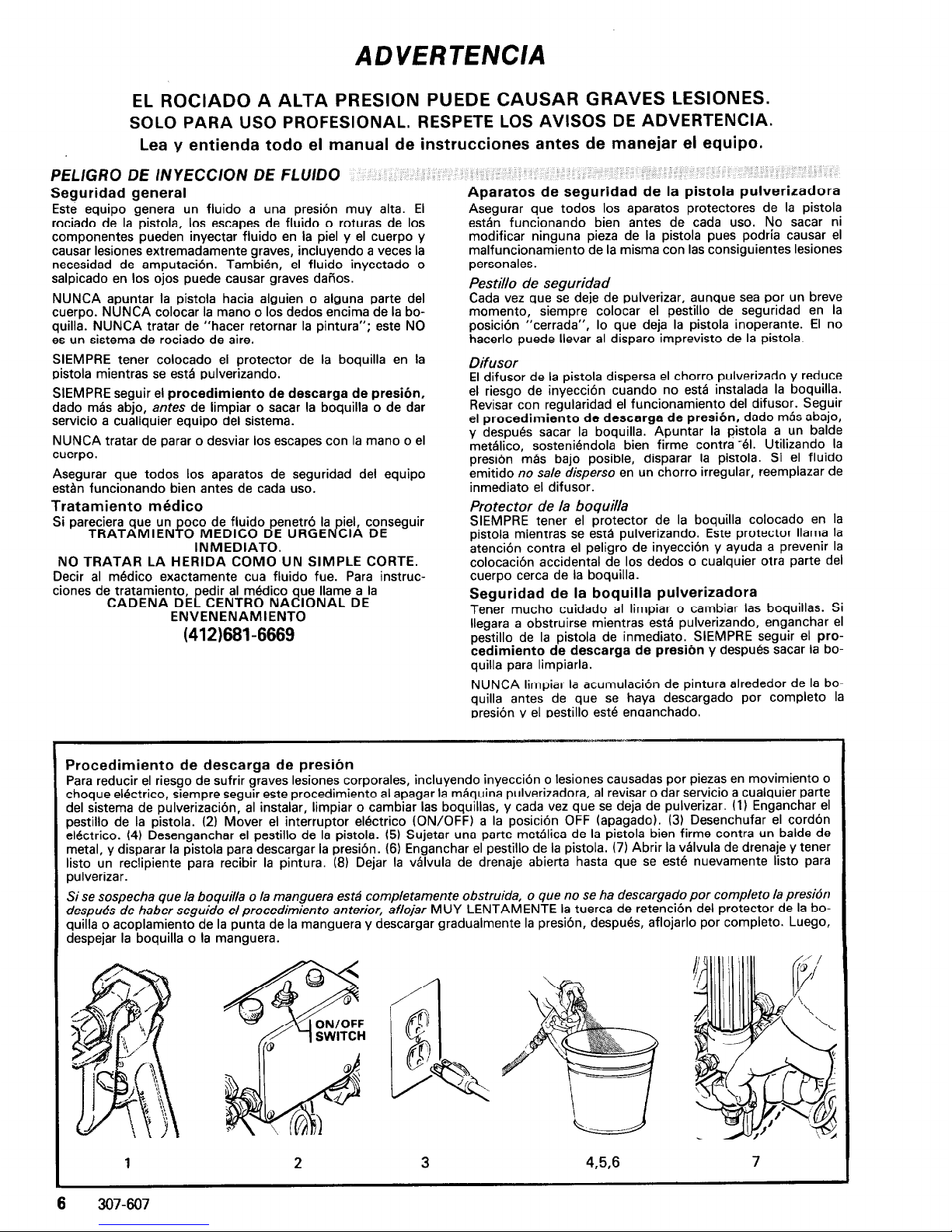
Procedimiento de descarga de presibn
Para reducir el riesgo de sufrir graves lesiones corporales, incluyendo inyeccion o lesiones causadas por piezas en movimiento o
choque electrico, siempre seguir este procedimiento al apagar la maquina pulverizadora, al revisar o dar servicio a cualquier parte
del sistema de pulverization, al instalar, limpiar o cambiar las boquillas, y cada vez que se deja de pulverizar. (1) Enganchar el
pestillo de la pistola. (2) Mover el interruptor electrico (ON/OFF) a la position OFF (apagado). (3) Desenchufar el cordon
electrico. (4) Desenganchar el pestillo de la pistola. (5) Sujetar una parte metalica de la pistola bien firme contra un balde de
metal, y disparar la pistola para descargar la presion. (6) Enganchar el pestillo de la pistola. (7) Abrir la valvula de drenaje y tener
listo un reclipiente para recibir la pintura. (8) Dejar la valvula de drenaje abierta hasta que se este nuevamente listo para
pulverizar.
Si se sospecha que /a boquilla o la manguera estii completamente obstruida, o que no se ha descargado por complete la presidn
despubs de haber seguido elprocedimiento anterior, afiojar MUY LENTAMENTE la tuerca de retention del protector de la boquilla o acoplamiento de la punta de la manguera y descargar gradualmente la presion, despues, aflojarlo por complete. Luego,
despejar la boquilla o la manguera.
1
2 3
456
7
6
307-607
Page 7
PELlGRO POR MAL US0 DEL EQUIP0
Seguridad general
Cualquier mal uso del equip0 pulverizador o 10s accesorios, tal
coma sobrepresurizaci6n, modificacibn de piezhs, uso de
materiales y productos quimicos incompatibles, o utilizaci6n
de piezas daiiadas o desgastadas, puede hacen que se rompan
y causen la inyecci6n de fluid0 u otras lesiones corporales
graves, incendio, explosi6n o dafion a la propiedad.
NUNCA alterar o modificar ninguna pieza de este equipo; el
hacerlo podria causar una averia.
REVISAR con regularidad el equip0 pulverizador y reparar o
reemplazar de inmediato las piezas daiiadas o desgastadas.
Presi6n del sistema
Esta pulverizadora puede desarrollar 207 barias (3000 psi) de
PRESION DE TRABAJO MAXIMA. Asegurar que todo el
equip0 pulverizador y sus accesorios tienen la capacidad para
aguantar la presi6n mhxima de trabajo de esta pulverizadora.
NO exceder la presibn mBxima de trabajo de ninglin componente o accesorio de este sistema.
Compatibilidad de fluid0
ASEGURAR que todos 10s fluidos y solventes usados son
quimicamente compatibles con las piezas mojadas ilustradas
en la hoja de datos tknicos en la contratapa. Siempre leer las
instrucciones del fabricante del fluid0 y solvente antes de
usarlos en esta pulverizadora.
SEGURIDAD EN EL US0 DE LAS MANGUERAS
El fluid0 que pasa a alta presi6n por las mangueras puede ser
muy peligroso. Si en la manguera se desarrolla un escape pequeiio, una rotura o rajadura debido a cualquier tipo de
desgaste, daiio o maltrato, el chorro a alta presi6n emitido por
alli puede causar una lesi6n por inyecci6n u otras lesiones corporales graves o dafion a la propiedad.
iTODAS LAS MANGUERAS PARA FLUIDOS TIENEN
QUE TENER GUARDAS DE RESORTE!
Estas protegen las
mangueras contra dobleces o retorceduras en 10s acoplamien-
tos o cerca de ellos, 10s que podrian traducirse en roturas de la
manguera.
Antes de usarlas, APRETAR bien firmes todas las conexiones.
El fluid0 a alta presi6n puede desalojar un acoplamiento suelto
o dejar que por BI escape un chorro a alta presi6n.
NUNCA usar una manguera que est& daRada. Siempre,
revisarla en busca de cortaduras, escapes, abrasibn, cubierta
abultada, o acoplamientos sueltos o dafiados. Si llegara a encontrarse cualquiera de estas condiciones, reemplazar de inmediato la manguera. NO intentar reacoplar una manguera de
alta presi6n o enmendarla con cinta adhesiva u otro material
similar. Una manguera que ha sido remendada no aguante el
fluid0 a alta presi6n.
MANEJAR Y PASAR CUIDADOSAMENTE LAS
MANGUERAS. No tirar de las mangueras para mover el
equipo. No usar fluidos o solventes que Sean incompatibles
con el tubo interno y la cubierta dela manguera. NO exponer
las mangueras a temperaturas sobre 62°C (180°F) o bajo
-4OT (-40°F).
Continuidad del circuit0 de puesta a tierra de la
manguera
La continuidad del circuit0 de puesta a tierra apropiado es
esencial para mantener conectado a tierra el sistema
pulverizador. Es indispensable revisar la resistencia elktrica
maxima de las mangueras de aire y de fluid0 por lo menos una
vez a la semana. Si la manguera no tiene una etiqueta en la
cual se especifica la resistencia electrica maxima, ponerse en
contact0 con el proveedor o fabricante de la manguera para la
informaci6n sobre 10s limites de resistencia. Usar un metro de
resistencia en la gama apropiada para comprobar la resistencia; si excede 10s limites recomendados, reemplazarla de inmediato. Es muy arriesgado tener una manguera sin puesta a
tierra o con la puesta a tierra en malas condiciones. Leer tambikn la informaci6n sobre
RIESGO DE INCENDIO 0 EXPLO-
SION,
m8s arriba.
PELIGRO DE INCENDIO 0 EXPLOSION
El flujo a alta velocidad del fluid0 al pasar por la bomba y
manguera crea electricidad estatica. Si todas las partes del
equip0 pulverizador no tienen buena tierra, pueden ocurrir
chispas, convirtiendo al sistema en algo peligroso. Tambik,
pueden producirse chispas al enchufar o desenchufar el cord6n elkctrico. Estas chispas pueden inflamar 10s vapores de
10s solventes y el chorro de fluid0 pulverizado, particulas de
polvo y otras sustancias inflamables, sea al aire libre o bajo
techo, lo que podria causal una explosi6n o incendio y graves
lesiones corporales y daiios a la propiedad. Enchufar siempre
la pulverizadora a un tomacorriente que se encuentre a por lo
menos 6 m (20 pies) de la mBquina y del drea que se va a
rociar. No enchufar o desenchufar ningtin cordbn elktrico en
el lugar donde se estB rociando cuando todavia exista la
posibilidad de que queden vapores inflamables en el aire.
Puesta a tierra
Para reducir el riesgo de chispas esthticas, conectar a tierra la
pulverizadora y todo el otro equip0 de pulverizar que se use o
se encuentre en el lugar que se va a rociar. CONSULTAR el
c6digo elktrico de la localidad para las instrucciones sobre las
conexiones a tierra exigidas para la zona y tipo de equipo.
ASEGURAR de conectar a tierra todo este equip0
pulverizador:
1. Pulverizadora: enchufar el cord6n ektrico, o cable extensor, cada uno con un enchuf de tres patas en buen estado, a
un tomacorriente con puesta a tierra apropiado. No usar un
adaptador. Totos 10s cables extensores tienen que tener tres
hilos y una capacidad de 15 amperios.
2. Mangueras para fluidos: usar solamente mangueras con
puesta a tierra de una longitud combinada de 150 m
(500 pies), para asegurar buena continuidad a tierra. Referirse
tambibn al pBrrafo sobre
continuidad a tierra de la
manguera.
3. Pistola: hater la puesta a tierra conectandola a una
manguera de fluid0 y pulverizadora bien conectadas a tierra.
4. Objet0 que se estg rociando: de conformidad con el cddigo
local.
5. Todos 10s baldes de solvente usados durante el lavado, de
conformidad con el c6digo local. Usar solamente baldes de
metal, que Sean conductivos. No colocar el balde en una
superficie no conductiva, coma papel o cartbn, que interrumpe la continuidad a tierra.
6. Para mantener la continuidad a tierra durante e/ lavado o
descarga de presih, siempre apoyar una parte metalica de la
pistola bien firme contra el costado del balde de metal,
despuk apretar el gatillo.
Seguridad durante el lavado
Reducir el riesgo de lesiones por inyeccibn, chispas ektricas
o salpicaduras, siguiendo el procedimiento de lavado
especifico dado en la pagina 12 de este manual. Seguir el
pro-
cedimiento de descarga de presih
en la pegina 6, y quitar
la boquitla rociadora antes de lavar. Apoyar una parte metelica
de la pistola bien firme contra el costado de un balde de metal
y usar la presibn m8s baja posible de fluid0 durante el lavado.
PELIGRO DE LAS PIEZAS MOVILES
Las piezas en movimiento pueden pinchar o amputar dedos u
otras partes del cuerpo. MANTENERSE ALEJADO de las
piezas en movimiento durante el arranque o funcionamiento
de la pulverizadora. Desenchufar la pulverizadora y descargar
la presi6n antes de revisarla o darle servicio, para impedir que
arranque inesperadamente.
IMPORTANT
Se han adoptado las normas de seguridad del gobierno de 10s
Estados Unidos de Norteamerica bajo el Acta de Seguridad y
Salud Ocupacional. Deberan consukarse estas normas, en
especial las Generales, Parte 1910, y las Normas de Construcci6n. Parte 1926.
307-607 7
Page 8

lNTRoDUcTloN~;~~:~lr~,;~!:l:::, ;:,i;;;l,, c’jj(>:,;rli:i:.r;: ;‘ :;:.i‘!.,s ,:‘iac..:. i’ it,
t
p
ULTRATM433 BASIC COMPONENTS
Model 231433 shown
/Cl
PRESSURE CONTROL KNOB
ELECTRIC MOTOR
FLUID FILTER
DRIVE ASSEMBLY
r-lC)PIIIT ElPEnYCP
V.I.““. I YI.L~I\L.”
FLUID OUTLET-
RESET BUlTON
ON/OFF SWITCH
DISPLACEMENT PUMP
DRAIN VALVE
MAIN FLUID HOSE
WHIP HOSE
Your new UltraTM 433 Sprayer functions and operates
differently than other airless paint sprayers. This section
will help you become familiar with the sprayer before
operating it.
Pressure Control
The pressure control includes an ON/OFF switch for the
sprayer, the pressure adjusting control knob, a pressure
sensing device, and a current overload circuit breaker
with a manual reset button. Its function is to control the
motor speed so that the sprayer maintains constant
fluid pressure at the pump outlet.
Motor
The DC motor has sealed bearings and replaceable
motor brushes. Its function is to drive the displacement
pump at the rate needed to supply sufficient paint
volume at the selected pressure.
Working together, the pressure control and motor
cause the pump to cycle whenever there is fluid or
pressure demand. When the pump is cycling, the motor
sounds like an automobile starter cranking. When the
pump is not cycling, the motor hums, hums intermittently, or appears to have shut itself off. However, there
will still be power to the sprayer and it will stay
pressurized and ready to use unless you manually shut it
off and relieve pressure.
Because the motor is DC, it is less sensitive to low
voltage or voltage fluctuations than an AC motor, and
an extension cord of up to 150 feet (45 m) can be used.
Drive Assembly
The sealed drive assembly transfers power from the DC
motor to the displacement pump.
Displacement Pump
The positive displacement, volume-balanced pump provides equal fluid delivery on both the up and down
pump strokes. The pump has a wet-cup which, when
filled with Grace Throat Seal Liquid, helps prevent
damage to the throat packings and piston rod.
Fluid Filter
The fluid filter provides the final paint straining to help
avoid clogs in the hose and spray tip. The filter includes
a reusable element and a drain valve for relieving fluid
pressure when shutting off the sprayer.
Hoses
The grounded, nylon spray hoses have spring guards on
both ends. The 50 foot (15.2 m) hose has a l/4 in. ID.
The 3 foot (0.9 m), 3/16 in. ID whip hose allows flexible gun movement. The nylon hose material acts as a
pulsation dampener to absorb pressure fluctuations.
Spray Gun & Reverse-A-Clean III Spray Tip
Both the “Contractor” and “Flex” spray guns include a
trigger safety which prevents accidental triggering
when it is engaged (see the WARNING on page 3). The
Reverse-A-Clean III spray tip uses high pressure fluid to
remove clogs from the spray tip without removing it
from the gun. It includes a safety tip guard which helps
reduce the risk of injection injury.
8
307-607
Page 9
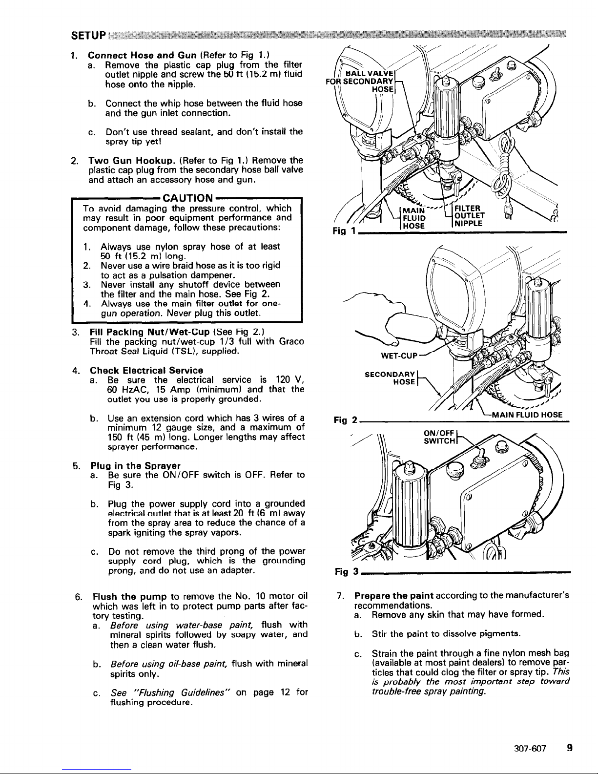
1. Connect Hose and Gun (Refer
to
Fig 1.1
a. Remove the plastic cap plug from the filter
outlet nipple and screw the 56 ft (15.2 m) fluid
hose onto the nipple.
b. Connect the whip hose between the fluid hose
and the gun inlet connection.
c. Don’t use thread sealant, and don’t install the
spray tip yet!
2. Two Gun Hookup. (Refer to Fig 1.1 Remove the
plastic cap plug from the secondary hose ball valve
and attach an accessory hose and gun.
CAUTION
To avoid damaging the pressure control, which
may result in poor equipment performance and
component damage, follow these precautions:
1. Always use nylon spray hose of at least
50 ft (15.2 m) long.
2. Never
use
a wire braid hose as it is too rigid
to act as a pulsation dampener.
3. Never install any
shutoff
device between
the filter and the main hose. See Fig 2.
4. Always use the main filter outlet for onegun operation. Never plug this outlet.
3. Fill Packing Nut/Wet-Cup (See Fig 2.)
Fill the packing nut/wet-cup l/3 full with Grace
Throat Seal Liquid ITSL), supplied.
4. Check Electrical Service
a.
Be sure the electrical service is 120 V,
66 HzAC, 15 Amp (minimum) and that the
outlet you use is properly grounded.
b. Use an extension cord which has 3 wires of a
minimum 12 gauge size, and a maximum of
156 ft (45 m) long. Longer lengths may affect
sprayer performance.
5. Plug in the Sprayer
a.
Be sure the ON/OFF switch is OFF. Refer to
Fig 3.
b. Plug the power supply cord into a grounded
electrical outlet that is at least 20 ft (6 m) away
from the spray area to reduce the chance of a
spark igniting the spray vapors.
C.
Do not remove the third prong of the power
supply cord plug, which is the grounding
prong, and do not use an adapter.
6. Flush the pump to remove the No. 10 motor oil
which was left in to protect pump parts after factory testing.
a.
Before using water-base paint, flush with
mineral spirits followed by soapy water, and
then a clean water flush.
b. Before using oil-base paint, flush with mineral
spirits only.
c. See “Flushing Guidelines” on page 12 for
flushing procedure.
Fig 1
1 HOSE
Fig
SECONDARY
FLUID HOSE
Fig 3
7.
Prepare the paint according to the manufacturer’s
recommendations.
a. Remove any skin that may have formed.
b. Stir the paint to dissolve pigments.
c. Strain the paint through a fine nylon mesh bag
(available at most paint dealers) to remove particles that could clog the filter or spray tip. This
is probably the most important step toward
trouble-free spray painting.
307-607
9
Page 10
WARNING
Pressure Relief Procedure
To reduce the risk of serious bodily injury, including injection or injury from moving parts or
electric shock, always follow this procedure
whenever you shut off the sprayer, when checking or servicing any part of the spray system,
when installing, cleaning or changing spray tips,
and whenever you stop spraying.
1. Engage the gun safety latch.
2. Turn the ON/OFF switch to OFF.
3. Unplug the power supply cord.
4. Disengage the gun safety latch.
5. Hold a metal part of the gun firmly to the
side of a metal pail, and trigger the gun to
relieve pressure.
6. Engage the gun safety latch.
7. Open the drain valve, having a container
ready to catch the drainage.
8. Leave the drain valve open until you are
ready to operate the sprayer again.
If you suspect that the spray tip or hose is completely CLOGGED, OR THAT PRESSURE HAS
NOT BEEN FULLY RELIEVED after following the
steps above, VERY SLOWLY loosen the tip guard
retaining nut or hose end coupling and relieve
pressure gradually. Then loosen the nut completely. Now clear the tip or hose obstruction.
1. Prime the Sprayer with Paint.
a. Close the filter drain valve (and the secondary
hose ball valve).
b. Don’t install the spray tip yet!
c. Put the suction tube into the paint container.
d. Turn the pressure adjusting knob all the way
counterclockwise to lower the pressure setting.
e. Disengage the gun safety latch.
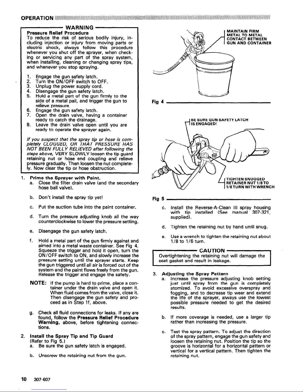
f. Hold a metal part of the gun firmly against and
aimed into a metal waste container. See Fig 4.
Squeeze the trigger and hold it open, turn the
ON/OFF switch to ON, and slowly increase the
pressure setting until the sprayer starts. Keep
the gun triggered until all air is forced out of the
system and the paint flows freely from the gun.
Release the trigger and engage the safety.
NOTE:
If the pump is hard to prime, place a container under the drain valve and open it.
When fluid comes from the valve, close it.
Then disengage the gun safety and proceed as in Step If, above.
g. Check all fluid connections for leaks. If any are
found, follow the Pressure Relief Procedure
Warning, above, before tightening connections.
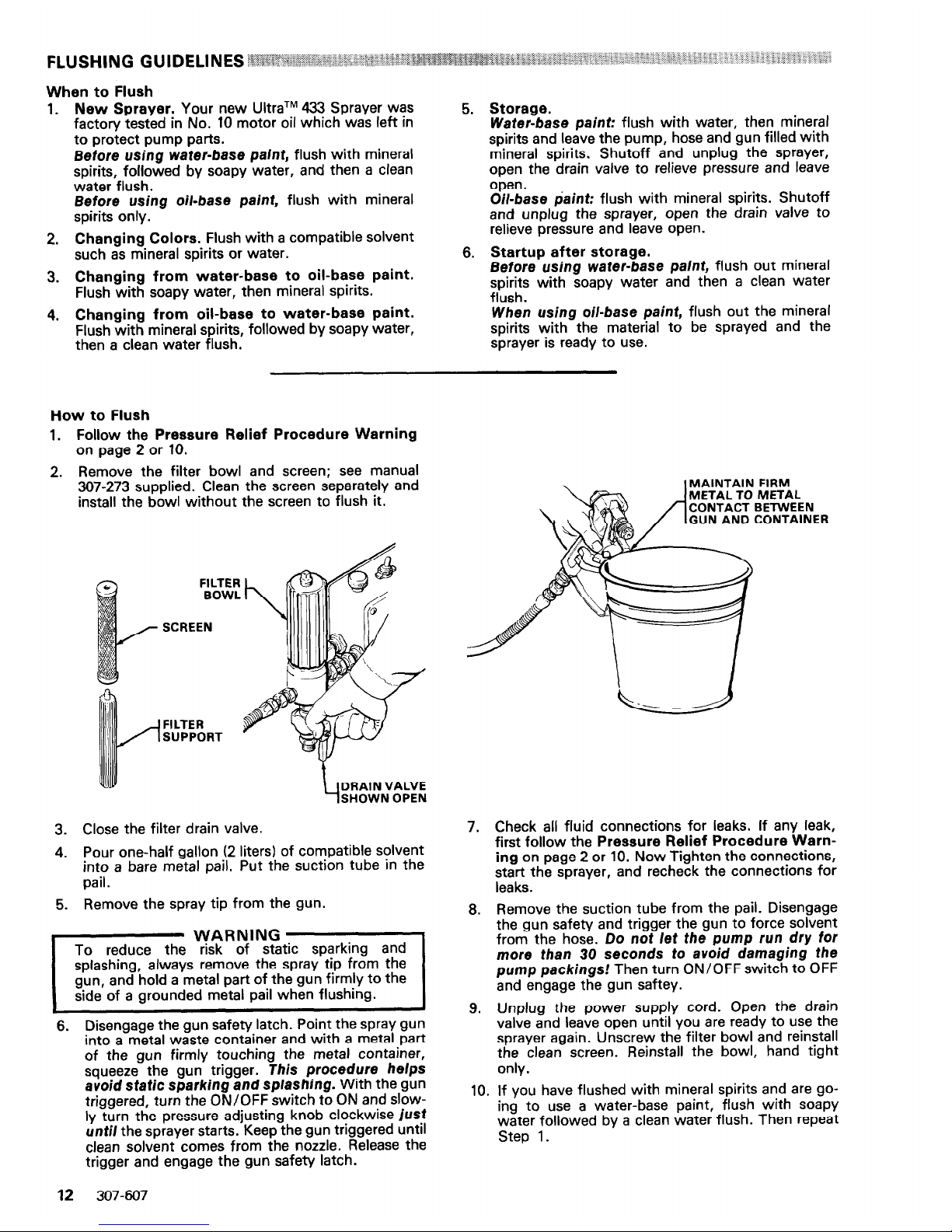
2. Install the Spray Tip and Tip Guard
(Refer to Fig 5.)
a. Be sure the gun safety latch is engaged.
b. Unscrew the retaining nut from the gun.
MAINTAIN FIRM
METAL TO METAL
CONTACT BETWEEN
GUN AND CONTAINER
Fig 4
BE SURE GUN SAFETY LATCH
IS ENGAGED!
TIGHTEN SNUGGED
RETAINER NUT 1/8TO
l/8 TURN WITH WRENCH
Fig 5
C.
Install the Reverse-A-Clean III spray housing
with tip installed (See manual 307-321,
supplied).
d. Tighten the retaining nut by hand until snug.
e. Use a wrench to tighten the retaining nut about
l/8 to l/6 turn.
I CAUTloN 1
Overtightening the retarnrng nut will damage the
seat gasket and result in leakage.
3. Adjusting the Spray Pattern
a. Increase the pressure adjusting knob setting
just until spray from the gun is completely
atomized. To avoid excessive overspray and
fogging, and to decrease tip wear and extend
the life of the sprayer, always use the lowest
possible pressure needed to get the desired
results.
b. If more coverage is needed, use a larger tip
rather than increasing the pressure.
c. Test the spray pattern. To adjust the direction
of the spray pattern, engage the gun safety and
loosen the retaining nut. Position the tip so the
groove is horizontal for a horizontal pattern or
vertical for a vertical pattern. Then tighten the
retaining nut.
10
307-607
Page 11

4. Cleaning a Clogged Tip
WARNING
To reduce the risk of serious bodily injury from injection, use extreme caution when cleaning or
changing spray tips. If the spray tip clogs while
1
spraying, engage the gun safety latch immediately, then follow the procedure in Steps 4a-4e,
I
below,
I
I
NEVER wipe off build up around the spray tip until
pressure is fully relieved and the gun safety latch is
engaged.
I
a. Clean the front of the tip frequently during the
day’s operation. First, follow the Pressure
Relief Procedure Warning in on page 10.
Then use a solvent-soaked brush to keep
material from building up and clogging the tip.
b. If the spray tip does clog, release the gun trig-
ger, engage the gun safety, and rotate the
spray tip handle 160°. See Fig 6.
c. Disengage the gun safety and trigger the gun
into a waste container. Engage the gun safety
again.
d. Return the handle to the original position,
disengage the gun safety, and resume spraying.
e. If the tip is stillclogged, engage the gun safety,
shutoff and unplug the sprayer, and open the
drain valve to relieve pressure. Clean the spray
tip as instructed in “Service” in instruction
manual 307-321, supplied.
SHUTDOWN AND CARE i : ; ‘.‘.I.:, ;A’:’
1. Check the packing nut/wet-cup daily. First
follow the Pressure Relief Procedure Warning
on page 10. Be sure the wet-cup is l/3 full of TSL
at all times to help prevent material buildup on the
piston rod and premature wear of packings. The
packing nut should be tight enough to stop
leakage, but no tighter. Overtightening may cause
binding and excessive packing wear. Use a screwdriver and light hammer to adjust the nut. See
Fig 7.
2. Clean the fluid filter often and whenever the
sprayer is stored. First follow the Pressure Relief
Procedure Warning on page 10. Refer to manual
307-273, supplied, for the cleaning procedure.
3. Flush the sprayer at the end of each work day
and fill it with mineral spirits to help prevent pump
corrosion and freezing. See “Flushing Guidelines”
on page 12.
.
CAUTION
Never leave water or any paint in the sprayer overnight to: (1) prevent pump corrosion; (2) to pre-
vent the material from freezing in the pump and
pressure control which can cause loss of pressure,
stalling or serious sprayer damage. Always use
mineral spirits for the final flush, relieve pressure,
and leave the mineral spirits in the sprayer.
4. For very short shutoff periods, leave the suction
tube in the paint, follow the Pressure Relief Pro-
cedure Warning on page 10, and clean the spray
tip.
5. Coil the hose and hang it on the hose rack when
storing it, even for overnight, to help protect the
hose from kinking, abrasion, coupling damage, etc.
ROTATE 1
Fig 6
Fig 7
307-607
11
Page 12
1.
2.
3.
4.
New Sprayer. Your new UltraTM 433 Sprayer was
factory tested in No. 10 motor oil which was left in
to protect pump parts.
Before using water-base paint, flush with mineral
spirits, followed by soapy water, and then a clean
water flush.
Before using oil-base paint, flush with mineral
spirits only.
Changing Colors. Flush with a compatible solvent
such as mineral spirits or water.
Changing from water-base to oil-base paint.
Flush with soapy water, then mineral spirits.
Changing from oil-base to water-base paint.
Flush with mineral spirits, followed by soapy water,
then a clean water flush.
5. Storage.
Water-base paint: flush with water, then mineral
spirits and leave the pump, hose and gun filled with
mineral spirits. Shutoff and unplug the sprayer,
open the drain valve to relieve pressure and leave
open.
Oil-base paint: flush with mineral spirits. Shutoff
and unplug the sprayer, open the drain valve to
relieve pressure and leave open.
6. Startup after storage.
Before using
water-base paint, flush out mineral
spirits with soapy water and then a clean water
flush.
When
using
oil-base paint, flush out the mineral
spirits with the material to be sprayed and the
sprayer is ready to use.
How to Flush
1. Follow the Pressure Relief Procedure Warning
on page 2 or 10.
2. Remove the filter bowl and screen; see manual
367-273 supplied. Clean the screen separately and
install the bowl without the screen to flush it.
FILTER
BOWL
SCREEN
FILTER
SUPPORT
DRAIN VALVE
SHOWN OPEN
3. Close the filter drain valve.
4. Pour one-half gallon (2 liters) of compatible solvent
into a bare metal pail. Put the suction tube in the
pail.
5. Remove the spray tip from the gun.
6. Disengage the gun safety latch. Point the spray gun
into a metal waste container and with a metal part
of the gun firmly touching the metal container,
squeeze the gun trigger. This procedure helps
avoid static sparking and splashing. With the gun
triggered, turn the ON/OFF switch to ON and slowly turn the pressure adjusting knob clockwise just
until the sprayer starts. Keep the gun triggered until
clean solvent comes from the nozzle. Release the
trigger and engage the gun safety latch.
FIRM
METAL
BETWEEN
CONTAINER
7.
8.
9.
10.
Check all fluid connections for leaks. If any leak,
first follow the Pressure Relief Procedure Warning on page 2 or 10. Now Tighten the connections,
start the sprayer, and recheck the connections for
leaks.
Remove the suction tube from the pail. Disengage
the gun safety and trigger the gun to force solvent
from the hose. Do not /et the
pump run
dry for
more than 30 seconds to avoid damaging the
pump packings! Then turn ON/OFF switch to OFF
and engage the gun saftey.
Unplug the power supply cord. Open the drain
valve and leave open until you are ready to use the
sprayer again. Unscrew the filter bowl and reinstall
the clean screen. Reinstall the bowl, hand tight
only.
If you have flushed with mineral spirits and are going to use a water-base paint, flush with soapy
water followed by a clean water flush. Then repeat
Step 1.
12
307-607
Page 13
TROUBLESHOOTING GUIDE
AND
REPAIR INSTRUCTIONS
307-607 13
Page 14
TROUBLESHOOTING GUIDE ;e:;::, ::
‘:,;,.
,, , j: .;:‘,
’
This guide will help you identify the causes and solutions to sprayer problems. If you cannot identify and resolve the problem, or if “Return for repair” is indicated, contact your nearest authorized service agency for instructions on where and
how to return the sprayer for repair.
Pressure Relief Procedure
WARNING
To reduce the risk of serious bodily injury, including injection or injury from moving parts or electric shock, always
follow this procedure whenever you shut off the sprayer, when checking or servicing any part of the spray system,
when installing, cleaning or changing spray tips, and whenever you stop spraying.
I. Engage the gun safety latch.
2. Turn the ON/OFF switch to OFF.
3. Unplug the power supply cord.
4. Disengage the gun safety latch.
5. Hold a metal part of the gun firmly to the side of a metal pail, and trigger the gun to relieve pressure.
6. Engage the gun safety latch.
7. Open the drain valve, having a container ready to catch the drainage.
8. Leave the drain valve open until you are ready to spray again.
If you suspect that the spray tip or hose is completely CLOGGED, OR THAT PRESSURE HAS NOT BEEN FULLY
RELIEVED after following the steps above, VERY SLOWLY loosen the tip guard retaining nut or hose end coupling
1 and relieve pressure gradually. Then loosen the nut completely. Now clear the tip or hose obstruction.
I
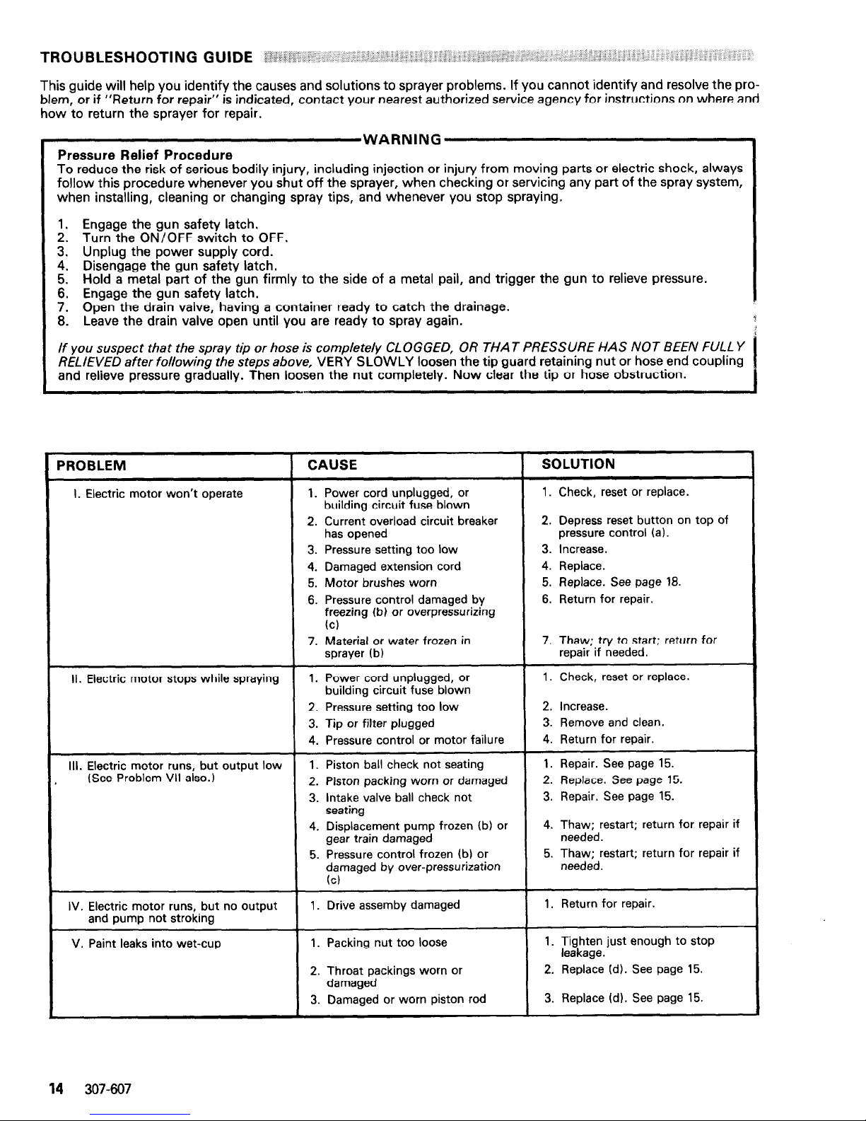
PROBLEM
I. Electric motor won’t operate
II. Electric motor stops while spraying
III. Electric motor runs, but output low
(See Problem VII also.)
CAUSE
1. Power cord unplugged, or
building circuit fuse blown
2. Current overload circuit breaker
has opened
3. Pressure setting too low
4. Damaged extension cord
5. Motor brushes worn
6. Pressure control damaged by
freezing (b) or overpressurizing
(cl
7. Material or water frozen in
sprayer fb)
1. Power cord unplugged, or
building circuit fuse blown
2. Pressure setting too low
3. Tip or filter plugged
4. Pressure control or motor failure
1. Piston ball check not seating
2. Piston packing worn or damaged
3. intake valve ball check not
seating
4. Displacement pump frozen (b) or
gear train damaged
5. Pressure control frozen (b) or
damaged by over-pressurization
(cl
SOLUTION
1.
Check, reset
or
replace.
2. Depress reset button on top of
pressure control (a).
3. Increase.
4. Replace.
5.
Replace. See page 18.
6. Return for repair.
7. Thaw; try to start; return for
repair if needed.
1. Check, reset or replace.
2. Increase.
3. Remove and clean.
4. Return for repair.
1. Repair. See page 15.
2. Replace. See page 15.
3. Repair. See page 15.
4. Thaw; restart; return for repair if
needed.
5. Thaw; restart; return for repair if
needed.
IV. Electric motor runs, but no output
and pump not stroking
1. Drive assemby damaged
1. Return for repair.
V. Paint
leaks into wet-cup
1. Packing nut too loose
2. Throat packings worn or
damaged
3. Damaged or worn piston rod
1. Tighten just enough to stop
leakage.
2. Replace fd). See page 15.
3. Replace (d). See page 15.
14 307-607
Page 15

PROBLEM
VI. Excessive surge (pulsing) at spray
gun
CAUSE
1. Filter partially clogged
2. Spray tip too big or worn
3. Paint too thick
4. Wrong type hose
5. Displacement pump check balls
dirty or sticking
6. Displacement pump check balls
and packings worn or damaged
7. Pressure control or motor
damaged
SOLUTION
1. Remove and clean.
2. Change tip.
3. Thin per paint manufacturer’s
recommendations.
4. Use minimum 50 ft (15.2 m)
grounded nylon hose; do not use
wire braid hose.
5. Flush, then remove and clean if
needed.
6. Replace. See page 15.
7. Return for repair.
VII. Not enough paint pressure (See Pro-
1. Pressure setting too low
1. Increase.
blem III also.)
2. Spray tip too big or worn
2. Change tip; see manual 307-321.
3. Motor brushes worn
3. Replace. See page 18.
4. Pressure control or motor
4. Return for repair.
damaged
VIII. Poor spray pattern
1. Clogged spray tip
2. Pressure setting too low
3. Outlet filter or hose partially
clogged
4. Spray tip too big or worn
5. Paint supply low or pail empty
6. Paint too thick
1. Clean. See manual 307-321.
2. Increase.
3. Clean; see manual 307-273.
4. Change tip; see manual 307321.
5. Fill; reprime to remove air.
6. Thin per paint manufacturer’s
recommendations.
IX. Spitting from spray gun
1. Paint supply low or pail empty
1. Fill, reprime to remove air.
2. Sprayer sucking air or gun
2. Tighten fittings; repair gun; see
needle not seating
manual 307-614.
X. Static sparking from gun
1. Sprayer or work not grounded
1. Check hose continuity and electrical ground connection.
(al Engage gun safety latch. Depress manual reset button on top of pressure control. If the sprayer continues to shut off, reduce
spraying pressure. If the problem isn’t corrected, return for repair.
(b) Freezing results from failure to replace water-base paint or flushing water with mineral spirits at shutdown.
(c) Overpressurization results from (I) using less than 50 ft (15.2 m) of nylon spray hose; (2) using wire braid hose; (3) adding a
shutoff device between filter and main hose; (4) plugging the main fluid outlet of the filter and using drain valve as a shutoff; and
(5) a clogged or incorrectly assembled filter.
(d) Fh;sumrz to keep packing nut l/3 full of Throat Seal Liquid to help prevent premature wear of throat packings and paint drying on
DISPLACEMENT PUMP REPAIR ’ I. -‘i ,. ::
.‘.i : :
.I :
Tools Needed:
Heavy duty vise
Plastic mallet
7/8” open end wrench Small screwdriver
2’ open end wrench
Before doing this procedure, follow the Pressure
Eha.i.ilnNG -1
Relref Procedure Warnrng on page 14 to reduce
the risk of an injection injury, injury from moving
Removing the Pump (Refer to Fig 8.1
1. Flush
the
pump,
if possible, and
relieve pressure
again. Stop the pump with the piston rod (223) in
its lowest position.
2. Unscrew the suction tube (42) from the pump. Hold
the wrench on the pump intake valve (222) to keep
the pump from loosening.
3.
Unscrew the hose (47) from
the nipple (46) on the
pump outlet and remove the hose.
4. Use a screwdriver to push the retaining spring (35)
aside and push out the pin (20).
Fig 8
307-607 15
Page 16

-206*
Fig 9
V-PACKING IN
THROAT FACE
LIPS OF V-PACKINGS LIPS OF V-PACKINGS
Fig 10
5. Loosen the locknut (38) and unscrew the pump
from the bearing housing (27).
Disassembling the Pump (Refer to Figures 9 and 10.)
1. Unscrew the intake valve (222) from the cylinder
(216). Remove the gasket (206). ball guide (215),
stop pin (207) and ball (204) from the valve. Clean
and inspect the parts for wear or damage, replacing
parts as needed. Always use a new gasket (included in Repair Kit 218-033).
2. Unscrew and remove the packing nut (221) and
plug (201).
3. Use a plastic mallet to tap the piston rod down,
then pull the rod out through the bottom of the
cylinder.
4. Remove the throat packings (209, 218) and glands
(211, 212).
5. Clamp the flats of the piston rod in a vise. Use a
7/8 in. wrench to loosen the retaining nut (214).
Then use the wrench to unscrew the piston valve
(224) from the rod.
6. Remove the backup washer (219), wiper (205),
packings (208, 217) and glands (213, 220).
Reassembling the Pump
Assemblv Notes:
(I)
(2)
(31
1.
2.
Use Repair Kit No. 218-033 to repair the displacement pump. Reference number in parentheses with
an asterisk, for exampe, (210*), show the parts included in thekit. Use all the new parts, even if the
old ones still look good as the old parts cause the
new ones to wear prematurely.
Alternate leather and plastic packings as shown in
Fig 3. Notice that the lips of the throat “V” packings face down, against pressure, and the lips of
the piston “V” packings face up, against pressure.
The lips of the U-cup wiper (205), face down. Incorrect installation damages the packings and results
in the pump leaking.
Coat the piston rod, inside of the cylinder and the
packings with a lightweight oil to help prevent
packing damage when inserting the piston rod.
Check the outside of the piston rod (223) and the inside of the cylinder (216) for scoring or scratches. If
the parts are damaged, new packings will not seal
properly. Replace these parts if needed.
Stack the backup washer (219*), wiper (205*),
female gland W!O”), packings (217*, 208”) and
male gland (213”) onto the piston valve. See
Figures 11 Et 12.
3.
4.
5.
Tighten the packing retaining nut (214) onto the
piston valve (224) and torque to 3 to 4 in-lb (0.34 to
0.35 N.m)-about finger tight.
Use a pen to make a light mark on the packings
where they align with one of the flats on the nut.
See Fig 11.
Place ball (203) on piston valve (224). Apply one
drop of thread locking compound on threads of
valve. Then hand tighten the valve assembly into
the piston rod just until the nut meets the face of
the rod. See Fig 12.
16 307607
Page 17
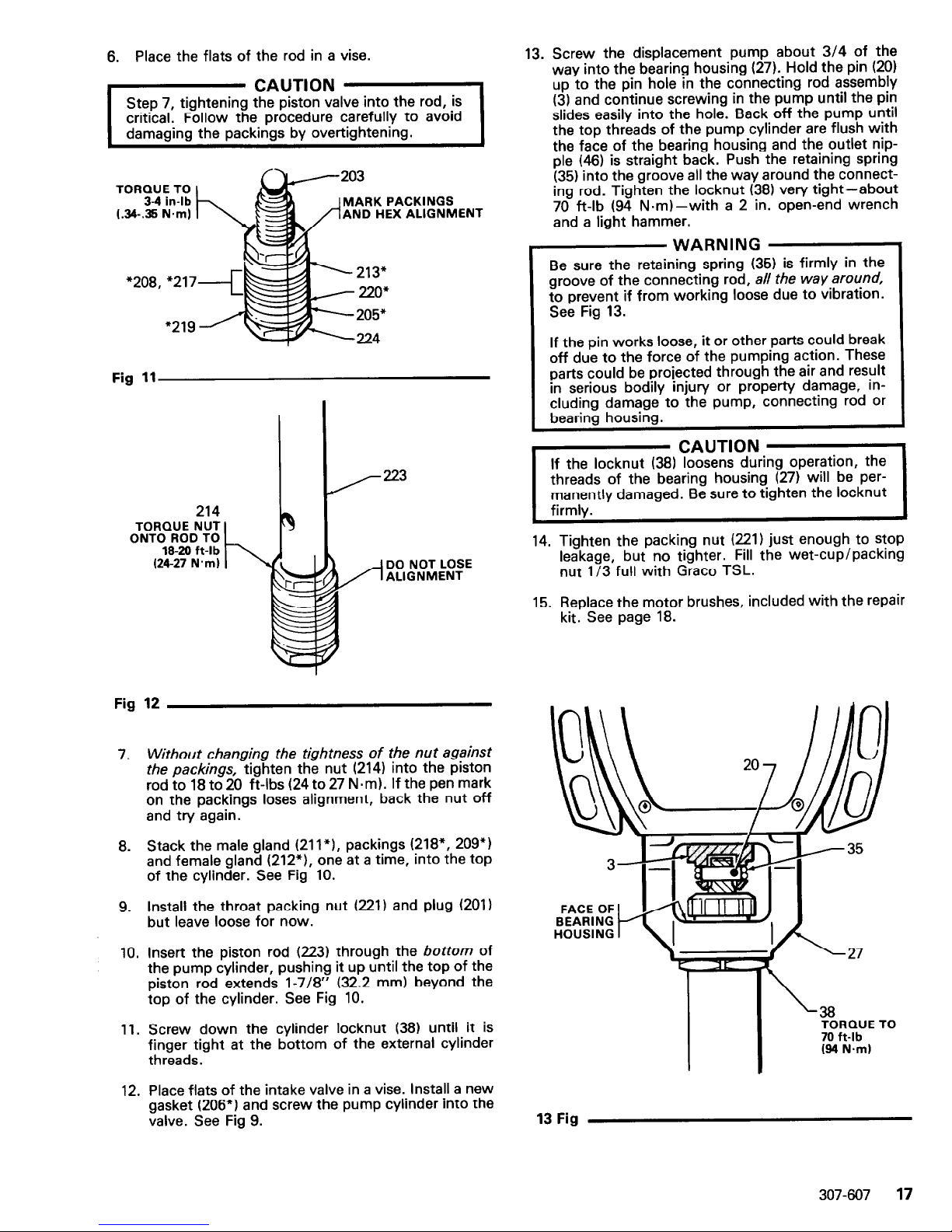
6. Place the flats of the rod in a vise.
203
TORQUE TO
3-4 in-lb
L
MARK PACKINGS
AND HEX ALIGNMENT
205*
224
Fig 11
214
TORQUE NUT
ONTO ROD TO
18-20 ft-lb
(24-27 N.m)
DO NOT LOSE
ALIGNMENT
Fig 12
7. Without changing the tightness of the nut against
the packings, tighten the nut (214) into the piston
rod to 18 to 20 ft-lbs (24 to 27 N-m). If the pen mark
on the packings loses alignment, back the nut off
and try again.
8. Stack the male gland (211*), packings (218*, 209”)
and female gland (212*), one at a time, into the top
of the cylinder. See Fig 10.
9. Install the throat packing nut (221) and plug (201)
but leave loose for now.
10. Insert the piston rod (223) through the bottom of
the pump cylinder, pushing it up until the top of the
piston rod extends l-7/8” (32.2 mm) beyond the
top of the cylinder. See Fig 10.
11. Screw down the cylinder locknut (38) until it is
finger tight at the bottom of the external cylinder
threads.
12. Place flats of the intake valve in a vise. Install a new
gasket (206”) and screw the pump cylinder into the
valve. See Fig 9.
13. Screw the displacement pump about 3/4 of the
way into the bearing housing (27). Hold the pin (20)
up to the pin hole in the connecting rod assembly
(3) and continue screwing in the pump until the pin
slides easily into the hole. Back off the pump until
the top threads of the pump cylinder are flush with
the face of the bearing housing and the outlet nip-
ple (46) is straight back. Push the retaining spring
(35) into the groove all the way around the connecting rod. Tighten the locknut (38) very tight-about
70 ft-lb (94 N-m)-with a 2 in. open-end wrench
and a light hammer.
WARNING
Be sure the retaining spring (35) is firmly in the
groove of the connecting rod, all the way around,
to prevent if from working loose due to vibration.
See Fig 13.
If the pin works loose, it or other parts could break
off due to the force of the pumping action. These
parts could be projected through the air and result
in serious bodily injury or property damage, including damage to the pump, connecting rod or
bearing housing.
. .
If the locknut (38) loosens during operation, the
threads of the beanng housrng (27) WIII be per-
manently damaged. Be sure to tighten the locknut
firmlv.
CAUTION
1
14. Tighten the packing nut (221) just enough to stop
leakage, but no tighter. Fill the wet-cup/packing
nut l/3 full with Grace TSL.
15. Replace the motor brushes, included with the repair
kit. See page 18.
38
TORQUE TO
70 ft-lb
(84 N.ml
13 Fig
307-607 17
Page 18

Tools Needed:
Phillips screwdriver
Flatblade screwdriver
NOTE:
New motor brushes are included with each
Packing Repair Kit 218-033. Replace them
when replacing the packings, and/or when
they have been worn to a minimum of g/16”
on the longest side.
1.
Remove the motor screws (1121, washers (113) and
cover (14). See Fig 14.
2.
Remove the screws (l-l), inspection covers (J) and
gaskets (K) on each side of the motor. See Fig 14.
3.
Loosen the brush lead terminal screw and remove
the lead.
4.
Push down on the spring clip slightly then pull the
clip away from and out of the brush holder. Refer to
Fig 15. Keep the spring clip.
5.
Remove and discard the brush.
6.
Inspect the commutator for excessive pitting, burning or gouging.
NOTE:
A black color on the commutator is normal.
Have the commutator resurfaced by a
qualified motor repair shop if the brushes
seem to be wearing too fast.
7. Place a new brush in the holder so the beveled
edges are as shown in the first part of Fig 15, and
the brush lead is routed as shown in the second part
of Fig 15.
8.
Slowly push the tabbed end of the spring clip into
the brush holder until the clip tab engages in the
holder and the rolled portion of the tension spring
rests squarely on the brush.
9.
Route the brush lead to the terminal and tighten the
terminal screws. Be sure the brush lead does not
touch any part of the armature or motor housing.
10. Test the brushes:
a. With the ON/OFF switch OFF, turn the
pressure control knob all the way counterclock-
wise to minimum pressure. Plug in the sprayer.
b. Turn the ON/OFF switch ON and slowly in-
crease the pressure until the motor comes up to
full speed.
C. Inspect the brush and commutator contact area
for excessive arcing. Arcs should not “trail” or
circle around the commutator surface.
WARNING
Do not touch the brushes, leads, springs or brush
holders while the sprayer is plugged in to avoid
electric shock and possible serious bodily injury.
CAUTION
Do not run the sprayer dry for more than 30
seconds while checking the brushes to avoid
damaging the displacement pump.
18
307-607
11. Reinstall the brush inspection covers, gaskets, and
screws. Reinstall the motor cover, screws and
washers.
Fig 14
SPRING CLIP
107-388
1
/-BRUSH HOLDER
RI-
BRUSH
r
107-w
TAB
r COMMUT AT IOR
SIDE VIEW OF MOTOR BRUSH INSTALLATION
MOTOR END BELL
TERMINAL SCREW 7
INSULATION
DETAIL OF MOTOR BRUSH
SHOWN WITH MOTOR LEAD
FACING BACK OF MOTOR
Fig 15
Page 19

PARTS DRAWINGS
AND
PARTS LISTS
307-607
19
Page 20
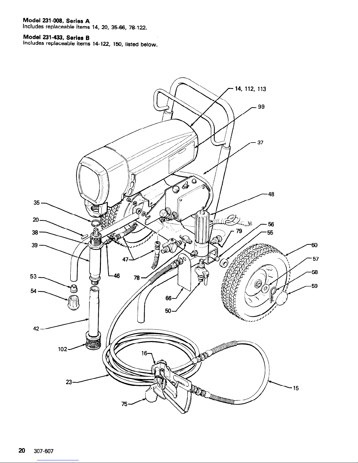
Model 231-008, Series A
Includes
replaceable
items
14, 20,
35-66, 78-122.
Model 231-433, Series B
Includes
replaceable
items
14-122,
150, listed below.
\
\
14, 112, 113
&
99
\\
4
4 A .’ /- 37
23
15
26 307-607
Page 21

Model 231408, Series A
Includes replaceable
Field-replaceable parts are listed below. Replacement of
items 14, 20, 35-66, 78-122, listed
below.
any other parts must be done by a qualified repair
agency.
Model 231433, Series B
Includes replaceable items 14-122, 150, listed below.
REF
NO.
1:
16
20
23
35
g
2
47
48
50
E
55
PART
NO.
218-362
214-701
217-593
176-818
210-541
176-817
179-885
178941
217-577
214-570
210-657
105-521
101-725
179-775
DESCRIPTION
CITY
COVER, motor; includes labels
1
HOSE, grounded, nylon; 3/16” ID;
3 ft (0.9 m) long; spring guards both
ends
1
GUN, airless
See manual 307-614 for parts
1
PIN, straight, hdls
1
HOSE, rounded, nylon; l/4” ID, 50
(15.2 my long spring guard both ends
SPRING, retaining
?
WARNING LABEL**
1
NUT, hex
1
DISPLACEMENT PUMP
See seoarate Darts list on
naae 20
1
1
SUCTlbN TUBE
CONNECTOR
HOSE; grounded, nylon,; l/4” ID;
29” (736 mm) long; spnng guard
both ends - - -
FILTER, fluid
See 307-273 for parts
BALL VALVE
See 306861 for parts
PLUG, tubing
CAP
SPACER 2
REF PART
NO. NO.
56
179-780
z 154-636 178-392
iz 12::1:
66 178-034
75 216-001
78 179-945
79 155-665
102 181-072
112 107-248
113 157-974
122 100509
150
DESCRIPTION QTY
AXLE
WASHER
E;gPkSAPpring
WHEEL
WARNING TAG””
SPRAY TIP KIT
See manual 307-321 for parts
ADAPTER, elbow; 7/16” stud;
l/4 x l/4 npt(f 1
UNION, adapter; 3/8 npsm(f) swivel
x 3/8 nptfm)
STRAINER
SCREW, math, round head, cross
head; No. 10-24x 2.5” long
WASHER, plain; 3/16”
PLUG; pipe; l/4 npt(f)
SPRAY TIP, Customer’s Choice
306 8 307 numbers in descriptions refer to separate instruction
manuals.
**Warning labels and tags supplied at no charge.
HOW TO ORDER REPLACEMENT PARTS
1.
To be sure you receive the correct replacement parts,
kit or accessories, always give all of the information
requested in the chart below.
2. Check the parts list to identify the correct
part
number;
do not use the ref. no. when ordering.
3. Order all parts from your nearest Grace distributor.
6 digit
PART
NUMBER QTY
PART DESCRIPTION
307-607 21
Page 22

Ref No. 39
217-577 Displacement Pump, Series B
Includes items
201
to 224.
REF
NO.
201
203
204
265
%
208
z
212
213
l
218
216
Repair Kit 218-033
(Must be purchased separately)
For pump packings and motor brushes. Includes all starred (“1 items in parts list below plus 2 motor brushes
(107-1491 and sealant (102~969) for piston.
PART
NO.
179-810
l
105-444
l
105-445
l
107-093
l
150-429
*178-938
l 178-939
l
178-940
* 178-942
l
178-943
‘178944
DESCRIPTION
PLUG
BALL
BALL
=&KEu;CUP
PIN, ball stop
V-PACKING, leather
V-PACKING, leather
GLAND, packing, male
GLAND, packing, female
GLAND, packing, male
QTY
REF
NO.
:
214 215
;
216 217
1
219 218
22
1
: 223
?24
“207
PART
NO.
178945
178948
178949
‘178964
‘178-965
*181-338
‘178969
179809
217-574
218-017
218-036
203"
214
213"
217"
205"
DESCRIPTION
QTY
NUT, hex
GUIDE, ball
CYLINDER
V-PACKING, plastic
V-PACKING, plastic
WASHER, backup
GLAND, Dackina
NUT, p&king/wet-cup
1
VALVE. intake (see separate parts list
below) .
ROD, piston
1
VALVE, piston
1
22 307-607
Page 23

SERVICE INFORMATION
I
ASSEMBLY PART
REF PART
CHANGED STATUS
NO. NO. NAME
I
217-577
OLD
178-966 Washer
Disp. Pump NEW
219 181-339
Washer
to Series B
I
ULTRA 433 TECHNICAL DATA
Power Requirements
Operating Range
Cycles/Gallon (liter)
Maximum Delivery
Power Cord
Inlet Paint Strainer
Outlet Paint Filter
Pump Inlet Size
Fluid Outlet Size
Weight
Wetted Parts
Dimensions
: 115 VAC, 60 Hz, 1 Phase, 15 AMP minimum
:0-3000 psi (O-207 bar)
:200 (53)
: 0.85 GPM (3.2 liter/min)
: No. 14 AWG, 3 wire, 8’6” (2.6 m) long
: 16 mesh, (I 190 micron), Stainless Steel Screen, reusable
:60 mesh, (250 micron), Stainless Steel Screen, reusable
:3/4 npt w/20° ID chamfer
: l/4 npsm from fluid filter
: 100 lb (45 Kg) approximately
: Aluminum, Delrin, Nitralloy, Nylon, Polyethylene,
Polyurethane, Rubber, Impregnated Leather, Stainless
Steel, Tungsten Carbide, Zinc-plated Steel
: Width: 22.5 in. (572 mm)
Height: 28.0 in. (711 mm)
Length: 26.0 in. (660 mm)
Factory Branches:Atlanta, Dallas, Detroit, Los Angeles, West Caldwell (N.J.1
Subsidiary
and Affiliate
Companies:Canada; England; Switzerland; Frence; Germany; Hong Kong; Japan
GRACO INC. P. 0. Box 1441 MINNEAPOLIS, MN 55440-1444
PRINTED IN U.S.A. 307-607 Z-83 Revised 1045
PTFEPTFEPTFE
 Loading...