

Graco Ultra 1500 Mark V 236-401, Ultra 1500 Mark V 236-400, Ultra 1500 Mark V, 236-401, 236-400 Instructions-parts List Manual
Page 1
INSTRUCTIONS–P
This manual contains important
warnings and information.
READ AND RETAIN FOR REFERENCE
220 VAC, 50 HZ, 12 AMP
ARTS LIST
308–263
Rev
D
Supersedes C
and PCN D
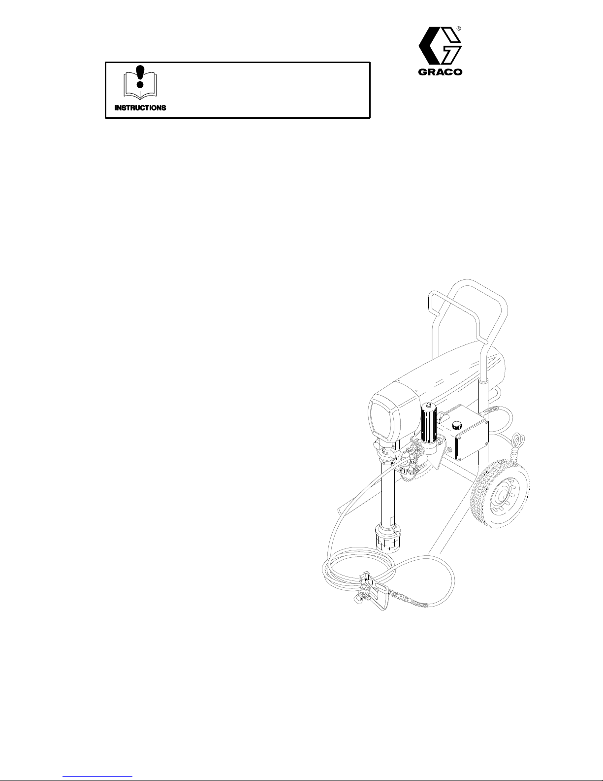
Ultra 1500 Mark V T
210 bar (3000 psi) Maximum Working Pressure
Model
This
a 1 m hose, a Contractor gun, RAC IV
guard and a Size 621 DripLess SwitchT
Model
This
a 1 m hose, a Silver Plus gun, a Heavy Duty RAC
IV
Patents
236–401, Series A
model includes a basic sprayer
, a 15 m hose,
DripLess
ip
236–400, Series A
model includes a basic sprayer
tip guard and a Size 629 DripLess SwitchT
Pending
, a 15 m hose,
tip
ip
exture Sprayer
GRACO INC. P.O. BOX 1441
COPYRIGHT
MINNEAPOLIS, MN
1993, GRACO INC.
55440–1441
Page 2
Table
PTFE
PTFE
PTFE
PTFE
PTFE
PTFE
Setup 4.
Operation 5
Flushing 7
Troubleshooting 9
Motor
Displacement
Motor
Pressure
Bearing
Connecting Rod Replacement
Drive
Parts
Parts
Technical
Dimensions 24
Warranty 24
. . . . . . . . . . . . . . . . . . . . . . . . . . . . . . . . . . . . . . . .
. . . . . . . . . . . . . . . . . . . . . . . . . . . . . . . . . . . . .
. . . . . . . . . . . . . . . . . . . . . . . . . . . . . . . . . . . . . .
Brush Replacement
Replacement
Control Replacement
Housing and
Housing Replacement
– Sprayer
– Displacement Pump
Data
. . . . . . . . . . . . . . . . . . . . . . . . . . . . . . . . . . . . .
of Contents
. . . . . . . . . . . . . . . . . . . . . . . . . . . . . . . .
. . . . . . . . . . . . . . . . . . . . .
Pump Repair
. . . . . . . . . . . . . . . . . . . . . . . . . . .
. . . . . . . . . . . . . . . . . . . . . . . . . . . . . .
. . . . . . . . . . . . . . . . . . . . . . . . . . . . . . .
. . . . . . . . . . . . . . . . . . . . . . . . . . . . . . . . . . .
. . . . . . . . . . . . . . . . . . . .
. . . . . . . . . . . . . . . . .
. . . . . . . . . . . . . . . . .
. . . . . . . . . . . . . . . . . . .
. . . . . . . . . . . . . . . . . . .
11.
12.
16.
17.
18.
19.
20.
22.
24.
Technical
Power
Requirements (full output)
W
orking Pressure Range
Cycles/Liter 27.5
Power
Outlet
Fluid Outlet Size
Wetted
. . . . . . . . . . . . . . . . . . . . . . . . . . . . . . . . . .
Cord
Paint Filter
Parts:
.
. . . . . . . . . . . . .
.
. . . . . . . . . . . .
.
. . . . . . . . . .
Displacement Pump
polyethylene,
Filter
NOTE:
marks of the DuPont Company
Aluminum, Carbon steel, Stainless Steel,
.
. . . .
and Delrin are a registered trade
.
Stainless
.
. .
Data
220 V
.
. . .
1
phase, 10 amp minimum
0 – 210 bar (0–3000 psi)
. . .
No. 12 A
250 micron (60 mesh)
steel screen, reusable
1/4 npsm from fluid filter
Carbon steel, Polyurethane,
.
AC, 50Hz,
WG, 3 wire, 3 m
Delrin, Leather
-
Dimensions
W
eight (basic sprayer)
Height 813 mm.
Length 616 mm.
Width 572 mm.
. . . . . . . . . . . . . . . . . . . . . . . . . . . . . . . . .
. . . . . . . . . . . . . . . . . . . . . . . . . . . . . . . . .
. . . . . . . . . . . . . . . . . . . . . . . . . . . . . . . . . .
.
. . . . . . . . . . . . . . . . . . . .
55.5 kg
Safety
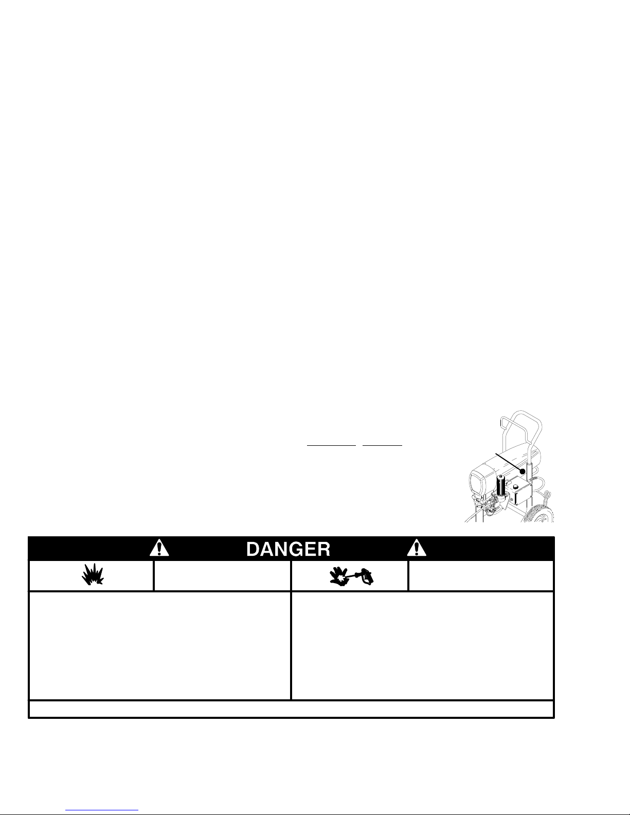
The
English language DANGER label shown below is
also on your sprayer
read English, order one of the following labels in an
appropriate language. Apply the label to the sprayer
The drawing shows the best placement of the new la
bels for good visibility
Order the labels directly from your Graco distributor
Spray painting, flushing or cleaning equipment with flammable
in confined areas can result in fire or explosion.
liquids
Use
outdoors or in extremely well ventilated
hoses, containers and objects being sprayed.
ment,
Avoid all ignition sources such as static electricity from plastic
cloths, open flames such as pilot lights, hot objects such as
drop
cigarettes,
turning
Failure
arcs
light switches on and off.
to follow this warning can result in death or serious injury
. If you have painters who do not
.
FIRE
AND
EXPLOSION HAZARD
areas. Ground equip
from connecting or disconnecting power cords or
Labels
.
-
.
Language
French 185–955
Spanish 185–962
German 186–042
Greek 186–046
Korean 186–050
Liquids
or
leaks – especially hose leaks.
-
Keep
body. Drain all pressure before removing parts.A void accidental
triggering
Never
In case of accidental skin injection, seek immediate
“Surgical
.
Failure
injury.
Apply
a label in
Part No.
can be injected into the body by high pressure airless spray
body clear of the nozzle. Never stop leaks with any part of
of gun by always setting
spray without a tip guard.
Treatment inch.
to follow this warning can result in
another language
at this location
SKIN INJECTION
HAZARD
the
safety latch when not spraying.
amputation or serious
READ AND UNDERSTAND ALL LABELS AND INSTRUCTION MANUALS BEFORE USE
Page 3
High
Observe All W
WARNINGS
Pressure Spray Can Cause Serious Injury
arnings. Read and understand all instruction manuals before operating equipment.
. For Professional Use Only.
FLUID
General
This
the
your
including the need for amputation. Also, fluid injected or
splashed into the eyes or on the skin can cause serious damage.
NEVER
NEVER put hand or fingers over the spray tip. NEVER try to
“blow back inch paint; this is NOT an air spray system.
ALWAYS have the tip guard in place on the spray gun when
spraying.
ALWAYS
cleaning or removing the spray tip or servicing any system
equipment.
NEVER
Be
each
Medical
If any fluid appears to penetrate your skin, get EMERGENCY
MEDICAL CARE AT ONCE. DO NOT TREAT AS A SIMPLE
CUT.
Note
is
important to treat the injury surgically as soon as possible.
not delay treatment to research toxicity. T
with some exotic coatings injected directly into the blood
stream. Consultation with a plastic surgeon or reconstructive
hand
Spray
Be sure all gun safety devices are operating properly before
each
cause
Safety
equipment generates very high fluid pressure. Spray from
gun, leaks or ruptured components can inject fluid through
skin and into your body and cause extremely serious injury
point the spray gun at anyone or at any part of the body
follow the Pressure Relief Procedure
try to stop or deflect leaks with your hand or body
sure equipment safety devices are operating properly before
use.
Alert––Airless Spray W
T
ell the doctor exactly what fluid was injected.
to Physician: Injection in the skin is a traumatic injury. It
surgeon may be advisable
ounds
oxicity is a concern
.
Gun Safety Devices
use. Do not remove or modify any part of the gun; this can
a malfunction and result in serious injury
INJECTION HAZARD
, below
, before
.
Do
.
Safety Latch
Whenever you stop spraying, even for a moment, always set
the
,
gun trigger safety in
the
gun inoperative. Failure to set the safety latch can result
accidental
triggering of the gun.
the closed or “safe inch position, making
Diffuser
.
The gun diffuser breaks up spray and reduces the risk of fluid
injection
regularly
remove
gun
the gun. If the fluid emitted
stream,
when the tip is not installed. Check dif
. Follow the
the spray tip. Aim the gun into a metal pail, holding the
firmly to the pail. Using the lowest possible pressure, trigger
replace the dif
Pressure Relief Procedure
is not
fuser immediately
diffused into an irregular
.
Tip Guard
ALWAYS have the tip guard in place on the spray gun while
spraying. The tip guard alerts you to the fluid injection hazard
and
helps reduce, but does not prevent, the
placing
your
tip.
fingers or any part of your body close to the spray
risk of accidentally
Trigger Guard
Always
have the trigger guard in place on the gun when spray
ing to reduce the risk of accidentally triggering the gun if it is
dropped
Spray T
Use extreme caution when cleaning or changing spray tips. If
the
immediately. ALWAYS follow the Pressure Relief Procedure
and
NEVER
fully
or bumped.
ip Safety
spray tip clogs while spraying, engage the gun trigger
then remove the spray tip to clean it.
wipe of
relieved and the gun trigger safety is engaged.
f build–up around the spray tip until pressure
in
fuser operation
, below
, then
safety
is
-
Pressure
To
reduce the risk of serious injury, including fluid injection,
splashing
from
dure whenever you shut off the sprayer, when checking or
servicing any part of the spray system, when installing,
cleaning or changing spray tips, and whenever you stop
spraying.
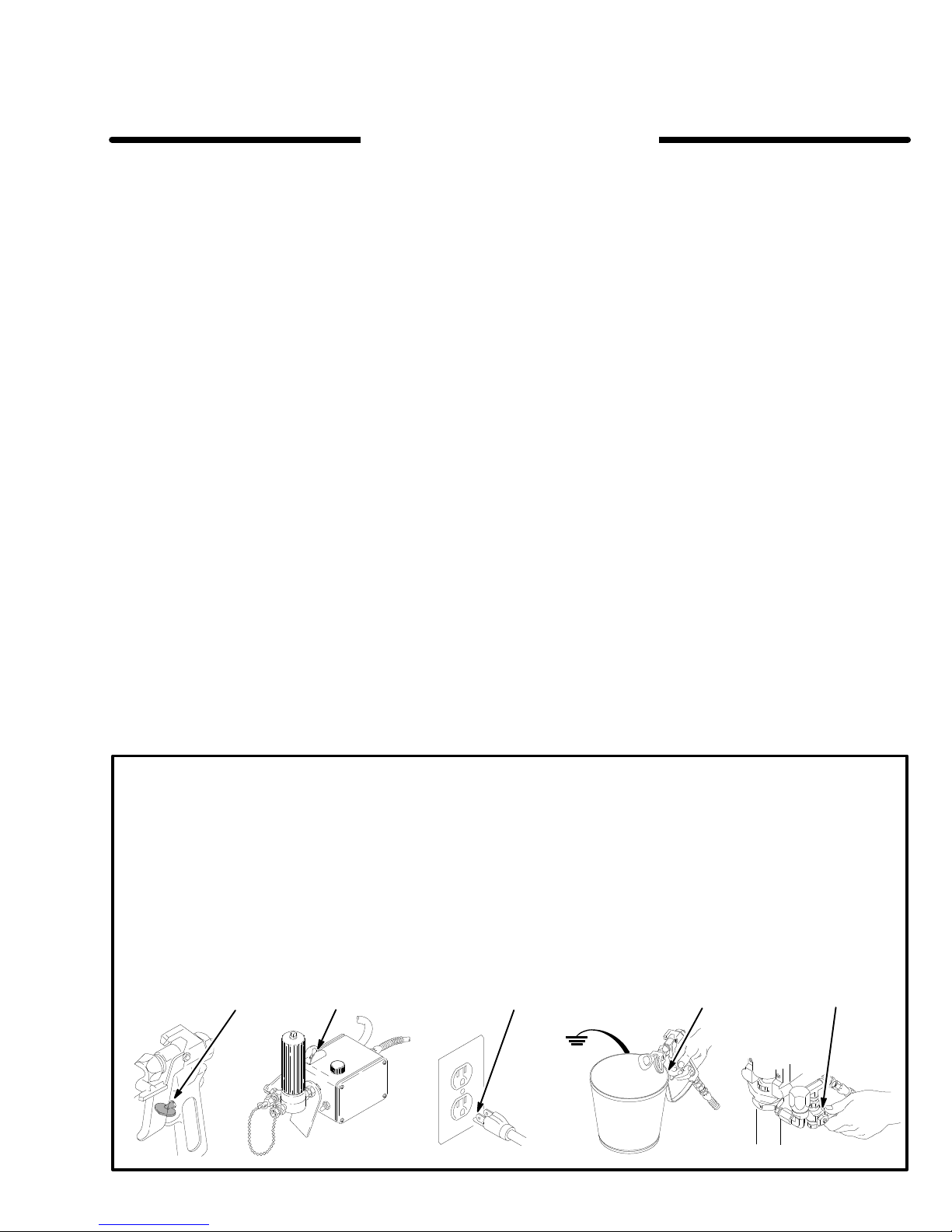
1. Lock
2. T
3.
Relief Procedure
fluid or solvent in the eyes or on the skin, or injury
moving parts or electric shock, always follow this proce
the gun trigger safety
urn of
f the ON/OFF switch.
Unplug the power supply cord.
.
1
4. Unlock
-
5.
6. Open
If you suspect that the spray tip or hose is completely
clogged,
low these additional precautions,
the
to
relieve the pressure gradually. Now loosen the part com
pletely.
2
3
the gun
firmly
to the
gun
to relieve the pressure.
Lock the gun trigger safety
the pressure drain valve, having a container ready
to
catch the drainage. Leave the valve open until you are
ready
to spray again.
or that the pressure has not been fully relieved,
retaining nut on the tip guard or loosen a hose coupling
Clear the tip or hose obstruction.
trigger safety
side of a grounded metal pail, and trigger the
. Hold a metal part of the gun
.
VER Y SLOWLY loosen
4
5
fol
-
-
Page 4

EQUIPMENT MISUSE HAZARD
System
This sprayer can develop
Working
sories used are rated to withstand this pressure. DO NOT exceed
cessory
General
Any misuse of the spray equipment or accessories, such as
overpressurizing, modifying parts, using incompatible chemicals and fluids, or using worn or damaged parts, can cause
them
or
erty
NEVER alter or modify any part of this equipment; doing so
could
Pressure
Pressure
the maximum working pressure
used in the system.
. Be sure that all spray
210 bar (3000 psi ) Maximum
equipment and acces
of any component or ac
Safety
to rupture and result in fluid injection, splashing in the eyes
on the skin, or other serious injury, or fire, explosion or prop
damage.
cause it to malfunction.
HOSE SAFETY
High
pressure fluid in the hoses can
hose develops a leak, split or rupture due to any kind of wear,
damage
cause
damage.
All
spring guards help protect the hose from kinks or bends at or
close
TIGHTEN
pressure
sure
NEVER
tire
movement of the hose couplings. If
ist, replace the hose immediately
pressure hose or mend it with tape or any other device. A repaired
or misuse, the high pressure spray emitted from it
a fluid injection injury or other serious
fluid hoses must have spring guards on both ends!
to the coupling which can result in hose rupture.
all fluid connections securely before each use. High
fluid can dislodge a loose coupling or allow high pres
spray to be emitted from the coupling.
use a damaged hose. Before each use, check the en
hose for cuts,
hose cannot contain the high pressure fluid.
leaks, abrasion, bulging cover
be very dangerous. If the
can
injury or property
The
, or damage or
any of these conditions ex
. DO NOT try to recouple high
FIRE OR EXPLOSION HAZARD
Static
electricity
hose. If every part of the spray equipment is not properly
grounded, sparking may occur , and the system may become
hazardous. Sparking may also occur when plugging in or unplugging
can
ignite fumes from solvents and the fluid being sprayed, dust
particles and other flammable substances, whether you are
spraying
and
serious injury and property damage.
If you experience any static sparking or even a slight shock
while
using this equipment, STOP SPRA
Check the entire system for proper grounding. Do not use the
system again until the problem has been identified and
corrected.
Grounding
To
reduce the risk of static sparking, ground the sprayer and
other spray equipment used or located in the spray area.
CHECK
tions
all
1.
2.
your local electrical code for
for your area and type of equipment. BE SURE to ground
of this spray equipment:
Sprayer:
move the grounding prong of the plug, and do not use an
adapter.
Fluid hoses:
150
m (500 feet) combined
continuity.
is created by fluid flowing through the pump and
a power supply cord or using a
indoors or outdoors, and can cause a fire or explosion
plug into a properly grounded outlet. Do not re-
Extension cords must have three wires.
use only grounded hoses with a maximum of
See
Hose Grounding Continuity.
hose length to ensure grounding
gasoline engine. Sparks
YING IMMEDIA
detailed grounding instruc
TELY.
all
CHECK all spray equipment regularly and repair or replace
worn
or damaged parts immediately
-
-
wear protective eyewear
Always
tor
as recommended by the fluid and solvent manufacturer
.
, gloves, clothing and respira
Fluid and Solvent Compatibility
All
chemicals used in the sprayer must be chemically compatible
with
the wetted parts shown in
2.
Consult your chemical supplier to ensure compatibility
not use 1,1,1-trichloroethane, methylene chloride, other ha
Do
logenated hydrocarbon solvents or fluids containing such sol-
vents in this equipment, which contains aluminum and/or zinc
parts.
Such
the
possibility of explosion, which could cause death, serious in
jury
and/or substantial property damage.
Handle
equipment.
of
the pump and gas engine. Do not use fluids or solvents which
are
not compatible with
NOT
or
below –40 C (–40 F).
use could result in a serious chemical reaction, with
and route hoses carefully
Keep hoses clear of moving parts and hot
expose Graco hose to temperatures above
the
TECHNICAL DATA on page
. Do not pull on hoses to move
the inner tube and cover of the hose. DO
82 C (180
Hose Grounding Continuity
Proper
hose grounding continuity is essential to maintaining a
grounded
fluid
tag on it which specifies the maximum electrical resistance,
-
contact
sistance
-
for your hose to check the resistance. If the resistance exceeds
the recommended limits, replace it immediately . An ungrounded
ardous.
3.
4.
5.
6.
7.
Flushing
Reduce the risk of fluid injection injury , static sparking, or
splashing
of
this manual. Follow the
3, and remove the spray tip before flushing. Hold a metal part
of
-
the gun firmly to the side of
lowest
spray system. Check the electrical resistance of your
hoses at least once a week. If your hose does not have a
the hose supplier or manufacturer for the maximum re
limits. Use a resistance meter in the appropriate range
or poorly grounded hose can make
Also read
Spray
gun:
erly
grounded fluid hose and sprayer
Object being sprayed:
Fluid supply container:
FIRE OR EXPLOSION HAZARD.
obtain grounding through connection
according to local code.
according to local code.
All solvent pails used when flushing,
code. Use only metal pails, which are conductive. Do not
place
the pail on a non–conductive surface, such as
or
cardboard, which interrupts the grounding continuity
To
maintain grounding continuity when
pressure
side
, always hold a metal part of the gun firmly to the
of a grounded metal pail, then trigger the gun.
your system haz
.
according to local
flushing or relieving
Safety
by following the flushing procedure given on page 7
possible fluid pressure during flushing.
Pressure Relief Procedure
a grounded metal pail and use the
MOVING PARTS HAZARD
Moving
parts
parts.
the
sprayer
before checking
it
from starting accidentally
can pinch or amputate your fingers or other body
KEEP CLEAR of moving parts when starting or
. Follow the
Pressure Relief Procedure
or servicing any part of the sprayer
.
.
.
surfaces
F
to a prop
paper
.
on page
operating
on page
, to prevent
-
-
-
-
-
-
3
4 308-263
Page 5
Setup
WARNING
Proper
electrical–grounding is essential to reduce
the risk of a fire or an explosion. A fire or an explo
sion can cause a serious injury and property dam
age. For the detailed grounding–instructions, refer
to the warning section,
HAZARD,
on page 4.
FIRE OR EXPLOSION
WARNING
If you supply the hoses and the spray gun for the
sprayer
hoses are electrically conductive. Be sure the spray
gun has a tip guard. Be sure that each part is rated
for at least 210 bar (3000 psi) working pressure
These precautions reduce the risk of a serious
injury
ing, over–pressurizing or rupturing the hose or the
gun.
, follow these precautions. Be sure the
, including skin injection, due to static spark
-
-
.
-
3.
Be sure the electrical service is 220 V
an electrical outlet that is properly grounded. Have
a licensed electrician attach an appropriate plug to
the power supply cord. Do not remove the ground
ing prong of the power supply cord. Do not use an
ungrounded adapter
three wires which have a minimum 2.5
gauge) size. Long extension cords reduce the per
formance of the sprayer
4. T
urn of
f the power switch (A). Plug the power
supply cord into a grounded electrical outlet which
is located at least 6 m (20 feet) away from the
spray area.
5.
If you are spraying texture material, remove the
screen from the fluid filter
procedure on page 8.
6.
Flush the pump before using it. Refer to page 8.
. Extension cords must have
.
. Refer to the Flushing
, 50 Hz. Use
mm2 (12
-
-
CAUTION
A damaged pressure control can cause poor
sprayer performance and may damage other parts
of the sprayer
damaging the pressure control.
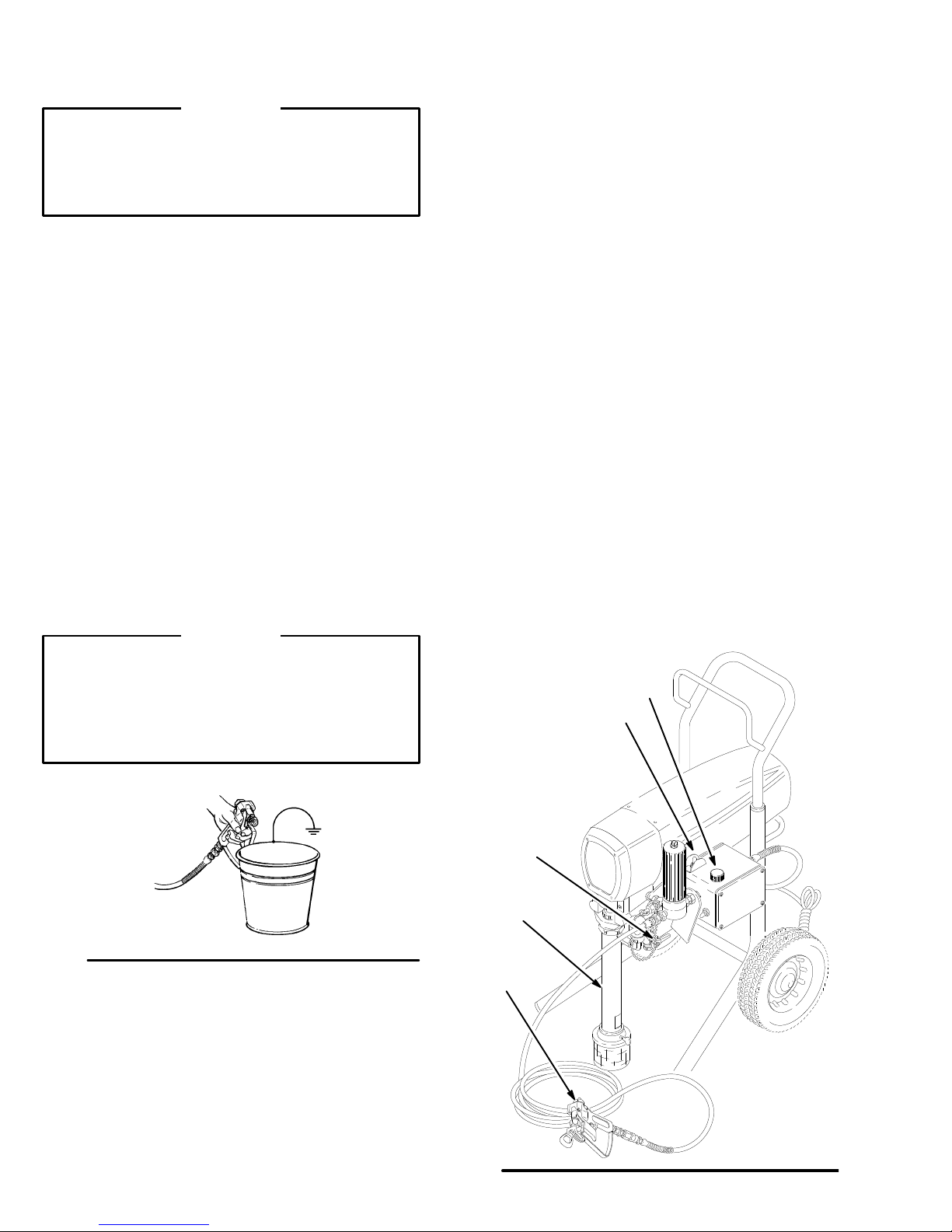
1.
Use a nylon spray hose (99) that is at least
15 m (50 feet) long.
2.
Never use a wire braid hose. It is too rigid to
absorb the pulsations of the fluid in the hose.
3.
Never install a shutoff device between the fluid
filter and the main hose. See Ref. B in Fig. 1.
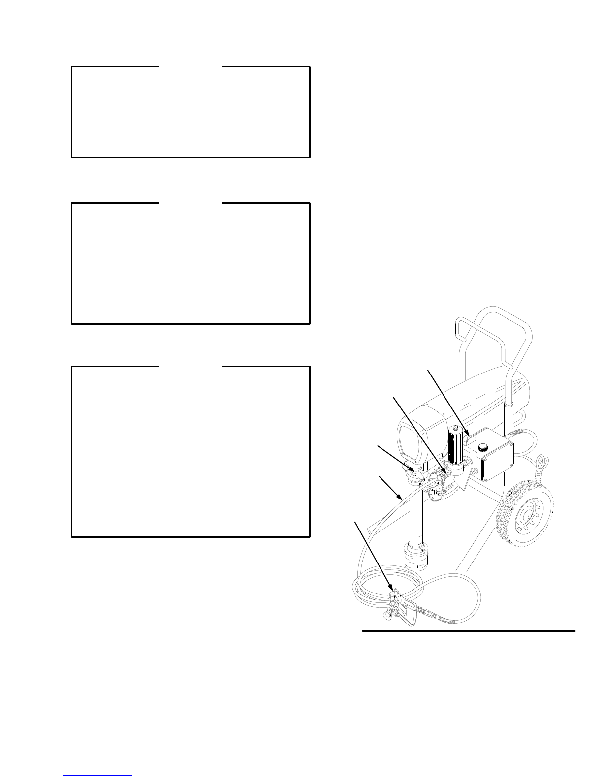
1.
Connect the gun (101) and the 15 m (50 feet) hose
(99). Do not install the spray tip yet.
2.
Fill the wet–cup (216) with Graco Throat Seal Liq
uid, supplied, until it is 1/3 full.
. Follow these precautions to avoid
A
B
216
99
101
-
Fig. 1
308-263 5
Page 6
Operation
WARNING
T
o reduce the risk of a serious injury
the
Pressure Relief Procedure W
3 before checking, adjusting, cleaning, and shut
ting of
f the sprayer
.
Startup
Always use this procedure to help ensure that the
sprayer is ready to operate and that you start the
sprayer safely
1.
Flush the sprayer before you use it for the first
time. Refer to page 8.
2.
Close the pressure drain valve (55).
3.
Do not install the spray tip until the pump is primed
with fluid!
4.
Put the pump (39) into the supply pail
5. T
urn the pressure–adjusting knob (A) counter
clockwise to the lowest setting.
6.
Unlock the gun trigger safety
.
, always follow
arning
.
on page
.
Check all fluid connections for leaking. If you find
8.
any leaks, relieve the pressure before tightening
the connections.
-
9.
Lock the gun trigger safety
and the tip guard (96, 103). Follow the instructions
supplied with the tip guard.
10.
Adjust the pressure.
a. Slowly
b.
c. T
-
, turn the pressure–adjusting knob (B)
clockwise just until spray from the gun is com
pletely atomized. T
fogging, and to lengthen the life of the spray
tip and sprayer
needed for good atomization.
If more fluid coverage is needed, use a larger
spray tip rather than increasing the pressure.
est the spray pattern. Follow this procedure
to adjust the direction of the spray pattern.
Lock the gun trigger safety
ing nut on the tip guard. T
hozontal position for a horizontal pattern. T
the tip guard to a vertical position for a vertical
pattern. T
, use the lowest fluid pressure
ighten the retaining nut.
. Install the spray tip
o reduce the overspray and
. Loosen the retain
urn the tip guard to a
urn
-
-
WARNING
T
ake precautions to reduce the risk of static spark
ing and splashing when you prime or flush the
sprayer
metal part of the gun firmly to the side of grounded
metal pail. See Fig. 2.
Fig. 2
7.
. Be sure the spray tip is removed. Hold a
Prime the pump. Squeeze the gun trigger and hold
it open. T
the pressure–adjusting knob (B) clockwise only
until the sprayer starts. Keep the gun triggered
until the air is forced out of the system and the
fluid flows freely from the gun. Release the gun
trigger and lock the gun trigger safety
urn of
f the power switch (A). Slowly turn
.
-
B
A
55
39
96,
103
NOTE: To avoid damaging the pump packings, do not
operate the sprayer without fluid in it for more than 30
seconds.
Fig. 3
Page 7
Operation
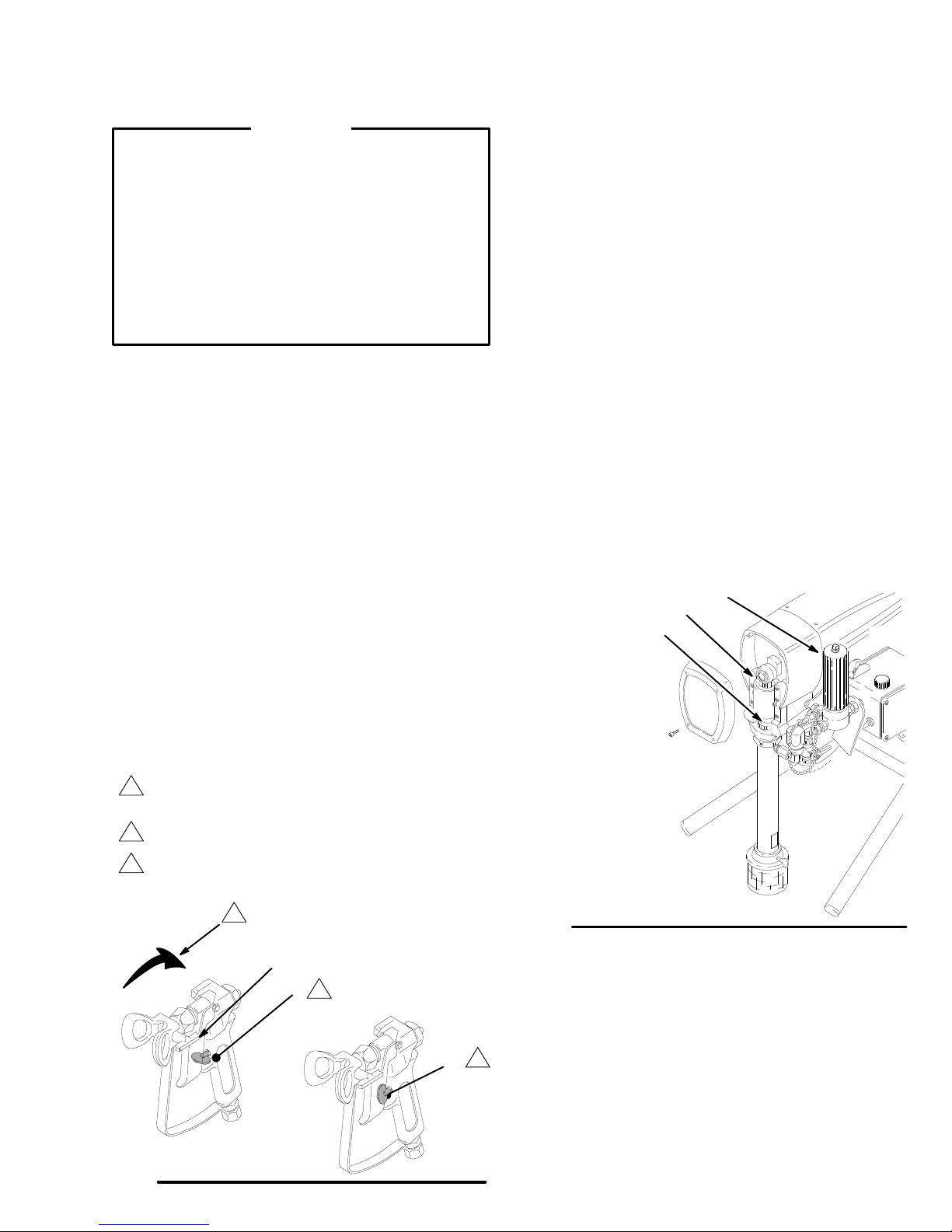
Cleaning a Clogged Tip
WARNING
Follow
these precautions to reduce the risk of a
serious injury when cleaning a clogged tip.
Do not hold a hand, a body
spray tip. Always point the gun toward the ground
or into a waste container when triggering the gun to
see if the spray tip is unclogged.
DO NOT try to “blow back inch fluid; this is NOT an
air spray sprayer
1.
Release the gun trigger
Lock the gun trigger safety (B).
2.
3.
Rotate the HD RAC IV handle 180. See Ref. A in
.
Fig. 4.
4.
Unlock the gun trigger safety (C).
5. T
rigger the gun into a waste container
Lock the gun trigger safety again. See Ref. A in
6.
Fig. 4.
, or a rag in front of the
.
.
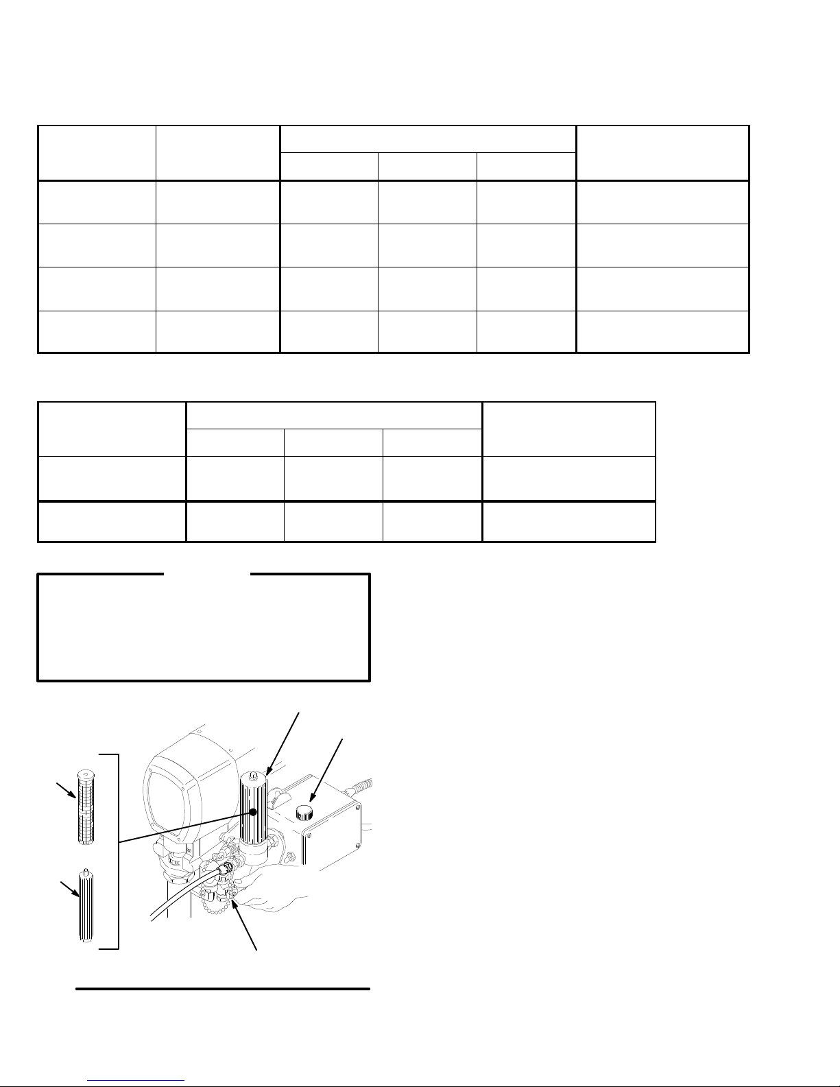
Shutdown and Care
1. Keep
2.
3.
the wet–cup (216) 1/3 full with Graco Throat
Seal Liquid. The liquid helps prevent fluid from
building up on the piston rod. Fluid build–up
causes the packings to wear prematurely
relieve the pressure before checking, filling or
tightening the wet–cup. See Fig. 5. Remove the
plug from the wet-cup. T
ighten the wet cup, which
is also the packing nut, just enough to stop leak
age. If you over–tighten the wet–cup, the packings
may bind and wear out more quickly
. Use a screw
driver and a light hammer to adjust the wet-cup.
Clean the fluid filter (48) often and whenever the
sprayer is stored. See manual 307–273 for the
cleaning procedure.
After each 100 hours of operation, fill the cavity of
the connecting rod (D) with motor oil. First Relieve
the pressure and then remove the front cover
Fig. 5.
. Always
-
-
. See
7.
Rotate the tip handle to the original position.
8.
Unlock the gun trigger safety
If the tip is still clogged, lock the gun trigger safety
9.
shut of
f and unplug the sprayer
.
, and open the
pressure drain valve to Relieve the pressure.
Remove the spray tip and soak it in solvent. Do
not scrape or chip debris from the spray tip.
10.
Resume spraying.
The
1
2
3
tip handle (A) is shown in the spraying
position. Rotate the tip handle 180 in the
direction of the arrow for clearing a clog.
T
rigger safety shown in the locked position.
T
rigger safety shown in the unlocked position.
1
A
B
2
48
D
216
,
Fig. 5
4.
When you shut of
f the sprayer for a short time,
leave the pump in the fluid–supply container
02067A
, re-
lieve the pressure, and clean the spray tip.
Fig. 4
3
C
5.
Before you store the sprayer
, flush it thoroughly
.
Always use mineral spirits for the final flushing.
Relieve the pressure.
6. T
0137
o protect the hose, coil it and hang it on the cart
handle
when storing the sprayer
.
Page 8
Flushing
1
Use this category when flushing a new sprayer and
when flushing the sprayer after it has been stored.
The system has
this fluid in it:
1
Oil-base solvent
or paint.
Oil-base solvent
or paint.
Water or waterbase paint.
Water or waterbase paint.
Use the following information to prepare the sprayer for storage.
The system has this
fluid in it:
Oil-base solvent or
paint.
W
ater or water-base
paint.
The next fluid to
be sprayed is:
Oil-base fluid in a
new color
W
ater-base paint.
W
ater-base fluid
in a new color
Oil-base paint.
Flush the sprayer in the order given.
First flush
Mineral spirits
W
arm, soapy
water
Flushing the sprayer in the order given.
First flush
Mineral spirits
Mineral spiritsWarm, soapy
W
arm, soapy
.
water
W
arm, soapy
water
Second flush
none none
Clean water
Second flush
none none
water
Clean water
Clean water
Third flush
Mineral spirits
Before you use the
Third Flush
Clean water
none
Mineral spirits
Before you store the
sprayer:
Relieve the pressure.
Relieve the pressure.
sprayer:
Prime the sprayer with
oil-base paint.
Prime the sprayer with
water-base paint.
Prime the sprayer with
water-base paint.
Prime the sprayer with
oil-base paint.
CAUTION
Never allow water to freeze in the pressure
control. A frozen pressure control prevents the
sprayer from being started and causes serious
damage to the pressure control. Pump out the
water with mineral spirits.
C
D
E
55
1.
Relieve the pressure.
2.
Remove the bowl (C) and the screen (D) from the
filter
. Leave the filter support (E) in place. Install
the bowl (C), only
3.
Close the pressure drain valve (55). See Fig. 8.
4.
Pour two liters of a compatible solvent into a
grounded metal pail. Put the pump in the pail.
A
5.
Remove the spray tip from the gun.
6. T
urn the pressure–adjusting knob (A) counter
clockwise to the lowest pressure setting.
. See Fig. 8.
-
Fig. 6
Page 9

Flushing
WARNING
T
ake precautions to reduce the risk of static spark
ing and splashing when you prime or flush the
sprayer
metal part of the gun firmly to the side of grounded
metal pail. See Fig. 7.
Fig 7
7.
. Be sure the spray tip is removed. Hold a
Hold a metal part of the gun firmly against a
grounded metal pail. See the W
T
rigger the gun. T
Slowly
, increase the pressure just until the sprayer
starts. Keep the gun triggered until all air is forced
out of the system and the solvent flows freely from
the gun. Release the trigger
safety.
urn on the power switch (B).
ARNING, above.
. Lock the gun trigger
Leave the pressure drain valve (55) open until you
9.
-
are ready to use the sprayer again. See Fig. 8.
10.
Clean the filter screen (D). Remove the bowl (C)
from the filter
and tighten it by hand. See Fig. 8.
11.
If you flushed with mineral spirits and now plan to
use a water–base paint, flush the sprayer with
soapy water and then with clean water
pressure.
D
E
. Install the screen. Install the bowl
. Relieve the
C
B
A
NOTE:
sure drain valve. Close the pressure drain valve when
fluid comes from it. Proceed as in Step 7.
8.
If the pump is hard to prime, open the pres
Remove the pump from the pail. Unlock the gun
trigger safety
the hose. T
do not operate the pump without fluid in it for more
than 30 seconds! Shut of
. T
rigger the gun to force solvent from
o avoid damaging the pump packings,
f the sprayer
.
-
Fig. 8
55
Page 10

Troubleshooting
WARNING
T
o reduce the risk of a serious injury
Pressure Relief Procedure W
before checking, adjusting or repairing the sprayer
, follow the
arning
on page 3
.
Read the entire T
TYPE OF PROBLEM WHA
The building’
opens.
The sprayer’s circuit breaker
opens.
roubleshooting section before disassembling the sprayer
If check is OK, go to next check
s circuit breaker
Check all electrical wiring to see if there is
damaged insulation.
Check to see if there are other electrical
appliances on the same circuit.
Check the position of the 10–12 (Lo–High)
amp switch.
Check to see if the motor rotor is dislocated.
Unplug the power supply cord. T
the motor’s fan blades with a screwdriver
Check to see if the motor has an electrical
short. Use an ohmmeter to check for electri
cal shorts between the electical leads of the
motor and the motor frame.
Check the electrical supply using a volt
meter
VAC.
T T
O CHECK
ry to turn
. The meter should indicate 210–250
.
WHA
T T
O DO
When check is not OK refer to this column
Replace any damaged wiring.
Shut of
f other electrical appliances on the
same circuit.
Put the switch in the 10–12 amp (LO) posi
tion.
Repair the gear train or the pump, if either of
them is damaged. Thaw the sprayer if it is
.
frozen–see the NOTE on page 11. Replace
the pressure control, if it is damaged.
Inspect the leads of the motor brushes to see
-
if they are damaged. Replace the motor
brushes or the motor as necessary.
Connect the sprayer to an electrical outlet
which has the correct voltage.
-
The sprayer will not operate.
The spray from the gun has a
poor pattern.
Check the pressure control knob. If the knob
is turned fully counterclockwise, which is the
minimum pressure setting, the motor will not
operate.
Check to see if the spray tip is clogged.
Refer to page 7.
Check the extension cord for visible dam
age. Check the extension cord outlet with a
volt meter or a test lamp.
Check the power supply cord for visible
damage such as broken insulation or broken
wires.
Check the electrical supply using a volt me
. The meter should indicate 210–250 V
ter
Check the motor for damage. Remove the
drive housing assembly
T
ry to rotate the blades of the fan manually
Check to see if the spray tip is worn.
. Refer to page 17.
-
AC.
Slowly increase the pressure to see if motor
will start.
Relieve the pressure. Refer to page 7 for
instruction on how to clean the spray tip.
Replace the extension cord.
Replace the power supply cord.
-
Reset the
circuit’s fuse. T
Replace the motor (1) if the blades of the fan
won’t rotate.
.
Relieve the pressure. Replace the spray tip.
Refer to the instruction manual supplied with
the spray tip.
building’
s circuit breaker
ry another electrical outlet.
, or replace
10 308-263
Page 11

Troubleshooting
TYPE OF PROBLEM WHA
If check is OK, go to next check
The motor operates and the
pump strokes, but the fluid
output is low or there is no fluid
output.
Check to see if the spray tip is worn.
Check the motor brushes for these
problems: Loose electrical leads or
terminals, a brush which is worn to less than
10 mm long, a broken or misaligned spring,
brushes which are binding in their holders.
Refer to page 12.
Check the armature of the motor for
electrical shorts by using an armature tester
(growler).
Check to see if the pump continues to stroke
when the gun trigger is released.
Check to see if the intake valve ball and the
piston ball are seating properly
Check for leaks around the throat packing
nut which may indicate that the packings are
worn or damaged.
T T
O CHECK
WHA
T T
O DO
When check is not OK refer to this column
Follow
Pressure Relief Procedure
Warning
your separate gun or tip manual.
Replace any damaged parts as needed.
Refer to page 12.
Replace the motor
Repair the pump. Refer to page 14.
Remove the intake valve and clean it.
.
Check the balls and seats for nicks; replace
if necessary
paint before using it to remove particles that
could clog the pump.
Replace the packings. Refer to page 14.
Also check the piston valve seat for
hardened paint or nicks and replace any
damaged parts. T
nut/wetcup.
, then replace the spray tip. See
. Refer to page 17.
. Refer to page 14. Strain the
ighten the packing
The motor operates but the
pump does not stroke.
The motor is hot and operates
intermittently.
Check the connecting–rod pin (20) in the
displacement pump. Refer to page 13.
Check for frozen or hardened paint in the
pump (39).
Be sure the crank in drive housing can
rotate.
Remove the
housing.
on the sprayer
sprayer.
Determine if the sprayer was operated at a
high pressure while using a small–orifice
spray tip. These conditions cause the motor
to function at a low RPM and produce
excessive heat.
Locate the sprayer where the ambient
temperature is no higher than 32C. Do not
place the sprayer in the direct sunlight.
Determine if the sprayer was turned on and
pressurrized, but not operating, for long
periods of time.
Plug in the sprayer and briefly turn
front cover from the drive
. T
urn of
f and unplug the
Replace pin, if missing. Be sure retainer
spring (35) is fully in groove all around
connecting rod. Refer to page 13.
Thaw.
See the NOTE below. Plug in sprayer
and turn on. Slowly increase pressure
setting to see if motor starts.
Check the drive housing assembly for
damage. Replace damaged parts. Refer to
page 20.
Decrease the pressure setting or use a
larger tip.
Move the sprayer to a shaded, cooler area,
if possible.
T
urn of
f the sprayer whenever you stop
spraying for a while and whenever you
relieve the pressure.
NOTE:
Thaw the sprayer if water or water–base paint has frozen in it. Place the sprayer in a warm area. Do not try
to start the sprayer until it has thawed completely
packings. Refer to page 14.
. If fluid has hardened or dried in the sprayer, replace the pump
308-263 11
Page 12

Motor
Brush Replacement
NOTE:
Replace the brushes when they have worn to
about 10 mm in length. Always check both of the
brushes. A Brush Repair Kit, part number 222–157,
and a new spring clip, part number 110–816, may be
purchased separately
.
NOTE: The replacement brushes may last only half as
long as the original brushes. To maximize the life of the
brushes,
allowing
operate the sprayer for at least one hour without
the pump to stroke. See Steps 10 to 12.
WARNING
Follow the
on page 3 to reduce the risk of a serious injury
1.
Relieve the pressure.
2.
Remove the shield (14). Remove the covers (A)
from both brush inspection ports. See Fig. 9.
Pressure Relief Procedure W
14
arning
.
10. T
est the brushes.
a.
Remove the connecting rod pin (20) only
Fig. 13, page 13.
b.
With the sprayer turned of
f, turn the pressure
control knob to the minimum pressure setting.
Plug in the sprayer
c. T
urn on the sprayer
.
. Slowly increase the pres
sure until the motor is at full speed.
d.
Inspect the contact area of the brush and com
mutator
. The arcs should not circle around the
commutator surface.
CAUTION
Do not touch the brushes, leads, springs, or brush
holders while the sprayer is plugged in, to reduce
the risk of an electric shock and a serious injury
11.
Install the brush inspection plates, gaskets, and
covers.
Operate the sprayer for at least one hour
12.
install the pump connecting rod pin. See page 13.
. Then,
. See
-
-
.
A
Fig. 9
3.
Push in the clip (D) to unhook it, and then pull out
the clip. See Fig. 10.
4.
Loosen the screw (F). Pull away the brush’
trical lead (E), leaving the motor’s electrical lead
(G) in place. Remove the brush (C) and the spring
(B). See Fig. 1
5.
Inspect the motor’s commutator for excessive pit
1.
ting, burning or gouging. A black color on the com
mutator is normal. If the brushes seem to wear too
quickly
, have the commutator resurfaced by a
qualified motor repair shop.
6.
Install the new brush (C) so its electrical lead is in
the long slot (K) of the brush holder (H). Slide the
terminal of the brush’
s electrical lead (E) under the
washer of the screw (F). Make sure the motor
electrical lead (G) is still connected the at the
screw. T
7.
Place the spring (B) on the brush (C) as shown in
ighten the screw (F). See Fig. 12.
Fig. 12.
s elec
’s
B
C
D
Fig. 10
01227
B
D
C
-
-
E
F
Fig. 11
The
spring must coil in
this direction.
The minimum brush
length is 10 mm.
G
H
01227
J
C
B
D
8.
Push in the clip (D) and hook it. See Fig. 12.
9.
Repeat this procedure for the other side.
12 308-263
Fig. 12
01227
Page 13

Displacement
Removing the pump
1.
Flush the pump, if possible. Relieve the pressure.
Stop the pump with the piston rod in its lowest po
sition, if possible.
2.
Remove the hose (47).
3.
Remove the intake screen (99).
4.
Push the retaining spring (35) up and push out the
pin (20).
5.
Loosen the locknut (38). Unscrew the pump from
the bearing housing (27) by one half turn.
6.
Remove the check valve assembly (A) from the
pump.
7.
Remove the pump.
Installing the pump
1.
Screw the pump into the bearing housing (27) until
the pin holes in the connecting rod assembly (29)
and the displacement rod (224) are aligned. Install
the pin (20).
2.
Continue to screw the pump into the bearing hous
ing until the top threads of the pump cylinder are
even with the face of the bearing housing and the
pump outlet faces straight back. Unscrew the
pump one half turn so the pump outlet is at the
side. Push the retaining spring (35) into the groove
all the way around the connecting rod. T
locknut (38) to 95 N.m (70 ft-lb).
See Fig. 13.
See Fig. 13 and 14.
ighten the
Pump Repair
Install the intake screen (99). See Fig. 13..
3.
4.
-
-
Install the check valve assembly (A).
5. T
ighten the wet-cup just enough to stop leakage,
but no tighter
until it is 1/3 full.
Fig. 13
. Fill the wet–cup with Graco TSL
27
35
224
20
38
39
99
47
A
02069A
WARNING
Push the retaining spring (35) completely and firmly
into the groove around the connecting rod to pre
vent it from working loose due to vibration.
If the pin works loose, the pin or other parts could
break off as the pump operates. The broken parts
could damage the sprayer or they could be pro
pelled toward the operator and cause a serious
injury.
CAUTION
If the locknut (38) loosens during operation, the
threads of the bearing housing (27) will be dam
aged. Ttighten the locknut firmly
Torque
1
-
-
-
.
2
Fig. 14
to the nut to 95 N.m. (70 ft–lb).
This
is the face
bearing
housing.
of the
29
27
2
20
35
38
1
02083
308-263 13
Page 14

Displacement
WARNING
Follow
the
Pressure Relief Procedure W
on page 3 to reduce the risk of a serious injury
arning
Pump Repair
lips of the v-packings in the throat
The
must face down.
The throat packings and glands.
The throat packings and glands.
.
NOTE:
223–41
Use the Packing Repair Kit, part number
1. The parts included in the kit are marked with
an asterisk (*). Use all the new parts in the kit. Clean
all parts. Inspect all parts, including the inside of the
sleeve (218) and the outside of the displacement rod
(224). Replace worn or damaged parts.
Disassembling the Pump
1. Unscrew
Clean the parts. If no further repair is needed,
reassemble the intake valve, using a new o-ring
(202*). See Fig. 15.
2.
Remove the packing nut (216) and plug (205). T
down the piston rod (224) using a plastic mallet.
Pull the piston rod out the bottom of the cylinder
(219). Remove the throat packings and the glands.
See Fig. 16.
3.
Clamp the piston rod (224) in a vise. Loosen the
piston nut (21
and remove all the parts. See Fig. 17.
and disassemble the intake valve (223)
1). Unscrew the piston valve (222)
WARNING
If the pump sleeve (218) cannot be removed easily
use the sleeve–removal tool, part number
235–376, as instructed in Step 4. T
risk of a serious injury
, do not use any other
method to remove the pump sleeve.
o reduce the
ap
,
Fig. 16
The
and glands.
*205
216
*209
*213
*208
piston packings
207*
219
224
224
211
NOTE:
If you have an old–style sleeve–removal tool,
part number 220–991, you can purchase just the
sleeve–removal extension, part number 188–734. The
extension makes the old tool equivalent to the tool
235–376.
4. T
o remove the pump sleeve (218), screw the large
nut (C) of the sleeve–removal tool into the top of
the cylinder (219). Screw the rod (B) downward to
push out the sleeve. Remove the tool. See Fig. 18.
219
220
204*
202*
223
226
Fig. 15
14 308-263
Fig.
Fig.
17
18
222
02086
B
C
219
218
Page 15

Displacement
Pump Repair
1
T
orque the intake valve to 146 N.m (1
2
The
lips of the V
3
The lips of the V
The lips of the U-cup seal must face down.
4
-packings in the throat must face up.
-packings in the piston must face down.
*209
2
*207
*208
10 ft–lb).
205
216
213*
219
224
NOTE:
Soak the leather packings in oil before reas
-
sembling the pump.
1.
Stack the following parts onto the piston valve
(222): the backup washer (214), the seal
(203*)–with the lips of the seal facing downward,
and the female gland (215*). Alternately install the
three plastic packings (212*) and the two leather
packings (206*) with the lips of the packings facing
up. Install the male gland (210*). See Fig. 19.
2.
Screw the retaining nut (211) on to the piston valve
(222). T
orque the nut to 0.35 N.m (4 in-lb). See
Fig. 20.
3.
Place the ball (225) on the piston valve (222). See
Fig. 20.
4.
2
Apply one drop of the adhesive, supplied, to the
threads of the piston valve. Hand tighten the pis
ton–valve assembly in to the piston rod just until
the nut (21
5. Note the alignment
(21
1). Use two wrenches to maintain the alignment
1) contacts the piston rod. See Fig. 20.
of the piston (222) to the nut
through Steps 6 and 7.
6.
Place the flats at the top of the piston rod (224) in
a vise.
*210
*206
3
*215
*214
220
*202
226
Fig.
19
Reassembling the Pump
NOTE:
an incorrect installation.
Follow all of the notes in the drawings to avoid
225*
217*
218
211
212*
203*
222
202*
223
3
4
1
02073
7.
Using two wrenches,
(21
1) against the piston rod. Torque the nut to 26
N.m (56 in–lb). See Fig. 21.
the nut (21
Torque
1
to 0.35 N.m (4 in–lb).
1)
Fig. 20
Apply one drop of the adhe
1
sive to the threads of the
piston valve (222).
T
orque the nut (21
2
rod to 27 N.m (56 in–lb).
Do not allow the nut (21
3
to move when screwing it
on to rod.
Fig.
21
1) against
carefully
-
1)
tighten the nut
225
211
222
224
211
222
308-263 15
1
02074
2
3
1
02075
Page 16

Displacement
Pump Repair
8. Place
9.
10.
11.
12.
13.
14.
15.
a new seal (217*) into the cylinder (219).
Lubricate the inside of the cylinder with oil. See
Fig. 20.
Install the male gland (208*) in the top of the cylin
der (219). Alternately install the three plastic pack
ings (213*) and the two leather packings (207*) so
that the lips of the packings face up. Install the fe
male gland (209). See Fig. 20.
Install the packing nut (216) loosely
plug (205) in the packing nut. See Fig. 20.
Lubricate the piston rod and the packings with oil.
Slide the assembly into the top of the sleeve (218).
See Fig. 22.
Slide the sleeve and the piston rod assembly into
the bottom of the cylinder (219). See Fig. 23.
Screw the cylinder locknut (38) downward to the
bottom of the external threads on the cylinder
T
ighten the locknut gently
Place the intake valve (223) in a vise. Install a new
o-ring (202*). Screw the cylinder (219) on to the
intake valve. T
(1
10 ft-lb). See Fig. 20.
Refer to page 13 to install the pump.
orque the intake valve to 146 N.m
.
. Install the
Lubricate.
1
224
-
-
-
Fig. 22
1
Lubricate
.
Fig. 23
1
218
217*
219
218
02087
1
02076
16 308-263
Page 17

Motor
Replacement
WARNING
Follow
the
Pressure Relief Procedure W
on page 3 to reduce the risk of a serious injury
NOTE:
1.
2.
3.
4.
5.
6. T
See Fig. 24 except where noted.
Remove the shield (14), the front cover (31), and
the pressure control cover (36). Disconnect the
hose (47).
Disconnect the motor’s electrical leads. See Fig.
25, page 18.
Unscrew the connector (44) on the pressure con
trol. Pull out the motor’s electrical leads.
Unscrew the connector (54) from the motor
Remove the conduit (22).
Remove the screws (51) from the drive housing.
Remove the screws (21,30) from the motor (1).
ap the rear of the pump (39) with a plastic mallet
to loosen the drive housing (18) from the motor
(1). Pull of
f the drive housing.
arning
.
.
NOTE:
Do not drop the gear cluster (9), which may
stay engaged in the front of the motor or in the drive
housing. Do not lose the balls (10) or drop them be
tween the gears. The balls usually stay in the recesses
for the shaft, but the balls could be dislodged. If the
balls are not in place, the bearings will wear prema
turely.
7.
Remove the screws (37). Lift of
8.
Mount the new motor on the cart. Install the
f the motor
.
screws (37).
9.
Slide the connector (54) over the electrical leads of
the new motor
connector into the motor
locknut until it contacts the motor
10.
-
Grease the gear cluster (9) and the pinion gear (G)
liberally
. Screw two or three threads of the
. T
ighten the connector
.
. Pack all the bearings in the front of the
’s
motor with grease. Be sure the balls (10) are in
place.
Place the bronze–colored washer (18b) and then
11.
the silver–colored washer (18a) on the shaft which
protrudes from the large gear in the drive housing
(18).
12.
Align the gears and push the drive housing (18)
straight onto the front of the motor (F) and its
locating pins.
13.
Continue to reassemble the sprayer
.
Torque
1
2
3
4
the screw to 34 N.m (300 in-lb).
The bronze–colored washer
Apply 175 cc of bearing grease.
The silver–colored washer
.
.
1
33
49
31
Fig. 24
51
27
18
14
21
63
1
G
4
18a
3
9
2
18b
54
37
44,22
36
30
63
40
10
47
41
02080
308-263 17
Page 18

Pressure
Control Replacement
WARNING
Follow
the
Pressure Relief Procedure W
on page 3 to reduce the risk of a serious injury
NOTE:
1.
2.
3.
4.
5.
See Fig. 26 except where noted.
Disconnect the hose from the outlet of the fluid
filter (48).
Loosen the nut (28). Loosen the swivel fitting (8).
Remove the fluid filter (48).
Remove the cover (36) from the pressure control.
Disconnect the four motor leads. See Fig. 25.
Unscrew the connector (44) from the pressure
control (43). Loosen the nuts on the connector
Pull out the conduit (22) and the motor’s electrical
leads from the pressure control.
Remove the screws (37) which hold the pressure
control (43) to the cart. Remove the pressure con
trol. Install the connector (44) on the new pressure
control.
arning
8.
Install the cover (36) on the pressure control.
.
9.
Connect the swivel fitting (8) to the fluid filter (48).
TIghten the nut (28) so that the filter is held
securely to the mounting plate (16).
1
The
seal (93) is located inside this fitting.
.
-
Black/
White(–)
6.
Remove the screws (84) and the mounting plate
(16) from the old pressure control. Install these
parts on the new pressure control.
7.
Install the new pressure control. Mount the pres
sure control with the screws (37). Place the seal
(93) around the motor’
the seal into the top of the connector (44). See Fig.
25.
s electrical leads and push
24
1
-
Fig. 25
93
44
41
40
84
16
44,22
43
36
Red
47
Black(–)
01897
28
Fig.
26
18 308-263
13
48
37
8
02077A
Page 19

Bearing
Housing and Connecting Rod
Replacement
WARNING
Follow
the
Pressure Relief Procedure W
on page 3 to reduce the risk of a serious injury
arning
9.
Install the screws (33). T
to 34 N.m (300 in–lb).
.
10.
Reinstall all the parts. Refer to page15 to install
the pump.
orque the screws evenly
NOTE:
get the crank (H) in its lowest position. T
crank manually
of the motor’s fan.
1.
2.
3. T
4.
5.
6.
Stop the sprayer at the bottom of its stroke to
o lower the
, use a screwdriver to rotate the blades
Remove the pump. Refer to page 1
Remove the front cover (31). Remove the screws
(33).
ap the lower rear of the bearing housing (27) with
a plastic mallet to loosen it from the drive housing
(18). Pull the bearing housing and the connecting
rod (29) straight of
Inspect the crank (H) and all other parts for exces
sive wear
Lubricate the inside of the bronze bearing (K)
evenly with motor oil. Pack the roller bearing (J)
liberally with bearing grease.
Assemble the connecting rod (29) and the bearing
housing (27).
. Replace worn or damaged parts.
f of the drive housing.
1.
Torque
33
-
31
to 3 N.m (300 in-lb)
Lubricate
J
29
27
49
35
20
38
18
H
K
7.
Clean the mating surfaces of the bearing housing
and the drive housing.
8.
Align the connecting rod with the crank (H). Align
the locating pins in the drive housing with the holes
in the bearing housing (27). Push the bearing
housing on to the drive housing or tap the bearing
housing into place using a plastic mallet.
Fig. 27
39
47
308-263 19
Page 20

Drive
Housing Replacement
WARNING
Follow
the
Pressure Relief Procedure W
on page 3 to reduce the risk of a serious injury
arning
6.
Remove the screws (30, 21) from the motor (1).
7. T
.
ap the drive housing (18) with a plastic mallet to
loosen it from the motor
straight of
f of the motor
. Pull the drive housing
.
NOTE:
NOTE:
get the crank (H) in its lowest position. T
crank manually
See Fig. 28 for this procedure
.
Stop the sprayer at the bottom of its stroke to
o lower the
, use a screwdriver to rotate the blades
of the motor’s fan.
1.
Remove the front cover (31). Remove the shield
(14).
2.
Disconnect the spray hose.
3.
Remove the screws (33) from the bearing
housing.
ap the rear of the pump (39) with a plastic mallet
4. T
to loosen it from the drive housing (18). Pull the
bearing housing (27) straight of
f of the drive
housing (18).
5.
Remove the screws (51) from the drive housing.
NOTE:
Do not drop the gear (9), which may stay en
gaged in the front of the motor or in the drive housing.
Do not lose the balls (10) or drop them between the
gears. The balls usually stay in the recesses for the
shaft, but the balls could be dislodged. If the balls are
not in place, the bearings will wear prematurely
8.
Use approximately 175 cc of the bearing grease,
.
supplied with the drive housing replacement kit, to
grease the gear cluster (9). Check to be sure the
balls (10) are in place.
9.
Place the bronze–colored washer (18b) and the
the silver–colored washer (18a) on the shaft which
protrudes from the large gear in the drive housing
(18).
10.
Align the gears. Push the new drive housing
straight onto the motor and its locating pins.
11.
Continue to reassemble the sprayer
. T
orque the
screws (33) to 34 N.m (300 in–lb).
-
1
2
3
4
Fig. 28
the screws to 34 N.m (300 in-lb).
Torque
The bronze–colored washer
Apply 175 cc of bearing grease.
The silver–colored washer
.
.
51
27
49
33
1
31
63
18
14
21
63
1
4
3
2
18b
18a
9
30
63
10
H
39
47
02082
Page 21

Parts–Displacement
PTFEPTFEPTFE
Pump
Model 235–731, Series A
Displacement
Includes items 202 to 226
Ref
No.
202 107–098*
203 110–284*
204 102–972*
205 183–171
206 183–174* V–P
207 183–175* V–P
208 185–474*
209 185–475*
210 185–476*
211
212 183–182* V–P
213 183–183* V–P
214 186–653* W
215 185–473*
216
217 183–172*
218
219
220
222
223
224
225 101–947*
226 185–522 ST
Pump
Part No.
183–179
183–186
183–361
188–361
185–312
235–203
222–691
235–730
Description Qty
SEAL, sleeve
SEAL, u–cup, polyurethane
BALL; sst
PLUG
ACKING, leather
ACKING, leather
GLAND, male
GLAND, female
GLAND, male
NUT
, hex, retaining
ACKING, plastic
ACKING, plastic
ASHER, backup
GLAND, female
NUT
, packing
O–RING,
SLEEVE, cylinder
CYLINDER 1
GUIDE, ball
VAL
VE, piston
VAL
VE, intake
ROD, piston
BALL
AND OFF
1
205
216
1
1
1
1
2
2
1
1
1
1
3
3
1
1
1
1
1
1
1
1
1
1
209*
213*
207*
213*
207*
213*
208*
219
224
*225
211
*210
*212
*206
*212
*206
*212
*Included in the
223–411.
time.
Keep a repair kit available to reduce down
Displacement Pump Repair Kit
217*
218
*215
*203
214
222
220
*204
*202
223
226
02064
308-263 21
Page 22

105d or
106d
Parts
106b, 106c
106a,
106e
– Sprayer
105e
3
2
1
98
61
14
105a,
105b,
105c
18
10
18b
9
18a
10
64
1
97
21
63
1
2
64
81
82
64
91
63
29
51
54
37
Ref
61
62
27
33
49
41
40
30
63
40
41
31
4
2
17
83
52
80
Ref 6
1
25
47
32
99
35
20
38
39
92
86
42
75
55
78
79
100,101,102
16
85
43
95
4
88
3
94
3
Ref 37
6
53
44
84
5
60
22
26
87
58
23
11
Ref 47
1
safety label.
A
2
An identification label.
3
An information label.
4
A caution label.
28
13
46
34
12
93
71,
1
77
45
37
57
8
48
50
8
15,
36,
5
2
02065A
02065
Page 23

Parts
– Sprayer
Model
236–401, Series A
This model includes a basic sprayer and a Contractor gun kit.
The
model includes items 1 to 105.
Model
236–400, Series A
This
model includes a basic sprayer and a Silver Plus gun kit
The model includes items 1 to 102 and 106.
Ref
No. Part No. Description Qty
1 235–726 MOTOR KIT 1
2 186–078
3 186–079
4 186–080
5 187–656 GASKET 2
6 220–636 CART 1
7 186–620
8 155–665 ADAPTER 3/8 inch npsm swivel
9 220–637 GEAR REDUCER 1
10 100–069
11 104–811 HUBCAP 2
12 220–285 CAP 1
13 100–322 LOCKW
14
15
16 185–539 BRACKET
17 111–590 BUTTON 2
18 220–879 DRIVE HOUSING KIT
183–204 MOTOR SHIELD KIT 1
110–885 SCREW
LABEL, identification, motor cover
LABEL, identification, motor cover
LABEL, identification, front cover
LABEL, ground symbol
x 3/8 npt(m)
BALL, steel, 1/4 inch diameter
ASHER, 7/16 inch
, No. 10–24 x 3/8 inch
, mounting
Includes 18 a, 18b, and one of 10
18a 183–209 .THRUST BEARING 1
18b 106–227 .SPACER 1
20 183–210
21 100–644 SCREW
22
065–099 CONDUIT, electrical
PIN, 3/8 x 1–1/8 inch
, 1/4–20 x 3/4 inch
specify length when ordering
23 224–263 POWER SUPPLY CORD 1
24 107–264
25 187–959 LABEL 1
26 154–636 WASHER 2
27 220–639 BEARING HOUSING KIT 1
28 150–513 NUT
29 220–640 CONNECTING ROD KIT 1
30 100–643 SCREW
31 183–168
32 108–850
33
34
35 183–169 RETAINING SPRING 1
36 186–918 COVER, pressure control 1
37 110–963 CAPSCREW
38 183–170 NUT
39 235–731 DISPLACEMENT PUMP
110–141 CAPSCREW
187–003
TERMINAL, female
, 7/16 inch
, 1/4–20 x 1 inch
COVER, housing 1
SCREW
ADAPTER, 1/4–18 npt(m x f)
5/16–18 x 3/4 inch
, No. 8–32 x 1–1/4 inch
, 1 13/16 unc–2b
see parts on page 21
40 100–214 LOCKW
41 100–188
42 223–125 CHECK VALVE 1
43 224–385 PRESSURE CONTROL KIT
44 102–932 CONDUIT
45 112–153 CIRCUIT BREAKER 1
46
47 222–516
48
162–453
236–789
NUT 5/16–18 unc–2a
includes
NIPPLE, 1/4 npsm x 1/4 npt,
1–3/16 inch long
HOSE, 3/8 npsm(f) x 14–1/2 inch
FLUID FIL
see
includes one of items 46 and 85
ASHER, spring, 5/16 inch
replaceable items 16, 23, 4 of 84
FITTING, 90
TER
manual 307–273 for parts
, 3/8–16 x 1–1/5 inch
, flange head,
1
296 mm
49 106–115 LOCKWASHER,
50 100–509 PLUG 1
51 108–849 CAPSCREW
52 110–243 RETAINING SPRING 2
53 108–691
54 108–460 CONNECTOR 1
55 235–725 DRAIN VALVE 1
57 178–034 TAG, WARNING 1
58 101–242 RETAINING RING 2
59 206–994 THROA
60 179–81
61
1
62 187–603
1
63
1
64 108–865 SCREW
71 177–762
75 109–544 ELBOW 1
1
77 181–608
78 803–088 TEE 1
2
79 161–889 SWIVEL UNION 1
80 109–032 SCREW
1
81 185–384 BRACKET 2
82 110–240 NUT 2
83 183–350 WASHER, 7/8 inch ID 2
1
84 106–078 SCREW
85 100–040 PLUG 1
4
86 100–083
1
87 106–170 STRAIN RELIEF BUSHING 1
88 185–565
89 100–035 SCREW
1
90 157–021 LOCKWASHER, No. 8 1
91 100–020 LOCKW
92 156–971 NIPPLE 1
1
93 107–447 SEAL 2
2
94 109–547
95 178–035
97 185–951
98 185–952
2
99 236–792
100 107–255 SHROUD 1
101 105–653 BOOT 1
102 112–153 ON/OFF SWITCH 1
2
105
2
105a 220–955 . CONTRACTOR GUN
4
105b 220–422 . RAC IV TIP GUARD 1
4
105c 221–621 . SwitchT
1
105d 223–541 .
ID,
7
105e 214–701 .
1
105f 157–350 . NIPPLE 1
1
106 236–383 SILVER PLUS GUN KIT
7
7
106a 235–460 . SILVER PLUS GUN
106b 222–674 . HEAVY DUTY RAC TIP GUARD 1
1
106c GHD–629 . HEAVY DUTY TIP
106d 214–705 .
1
106e 214–925 SWIVEL 1
1
1
220–633
105–510
236–384
Replacement Danger and W
are available at no cost.
PLUG, tubing
T SEAL LIQUID, 0.27 liter
1
WHEEL 2
HANDLE, cart 1
SLEEVE, cart handle
LOCKW
LABEL, W
LABEL, Identification
COUPLING, 3/8 to 1/4 inch
LABEL, pressure control
LABEL, 10/12 amp
LABEL, Caution
LABEL, Danger
LABEL, Danger
INLET FIL
CONTRACTOR GUN KIT
Includes items 105a to 105f
See manual 307–614 for parts
cpld 1/4 npsm, grounded,
spring guards both ends
0.9 m long, spring guards both ends
Includes items 106a to 106e
See manual 308–236 for parts
cpld 3/8 npsm(f), 15 m,
spring guards both ends
ASHER, 1/4 inch
, 8–32 x 3/8 inch
, pnh, 10–24 x 1/4 inch
, No. 10–24 x 3/8 inch
, No. 8–32 x 5/16 inch
ASHER, 0.194 inch ID
HOSE, nylon, 1/4 inch x 50 ft (15 m)
HOSE, grounded, nylon, 3/16 inch ID,
HOSE, grounded, nylon, 3/8 inch ID,
3/8 inch
, 1/4–20 x 3 inch
arning 1
TER SCREEN 1
ip, Size 621
, size 629
arning labels, tags and cards
4
2
2
1
2
6
10
1
4
4
1
1
1
2
1
1
1
1
1
1
1
1
1
1
1
1
1
Page 24

Manual
This
manual has been updated to make the following text and
part changes.
Technical
Strainer,
the
fluid
Model 231–207 has been obsoleted.
Data, page 2: Delete the reference to the Inlet Paint
this model does not have one. Delete the reference to
fluid outlet size, this
outlet size should be 1/4 npsm at the filter outlet.
model does not have inlet threads. The
Change Summary
Assembly
Changed
236–400
236–401
Part
Status
Add 99
Ref
No.
100
101
102
Part No.
236–792
107–255
105–653
112–153
Name
Screen
Shroud
Boot
Switch
The
Graco
warrants all equipment manufactured by it and bearing its name to be free from defects in material and workmanship on
the date of sale
warranty
defective, with the exception of defects in parts on the drive train/gear box, which will be repaired or replaced for forty-eight
months from the date of sale and the electric motor (excluding brush replacement, which is routine maintenance) or pressure
control assembly which will be repaired or replaced for twenty-four months from the date of sale. This warranty applies only when
the equipment is installed, operated and maintained in accordance with Graco’
This warranty does not cover
misapplication, abrasion, corrosion, inadequate or improper maintenance, negligence, accident, tampering, or substitution of
non–Graco component parts. Nor shall Graco be liable for malfunction, damage or wear caused by the incompatibility with Graco
equipment of structures, accessories, equipment or materials not supplied by Graco, or the improper design, manufacture, instal
lation, operation or maintenance of structures, accessories, equipment or materials not supplied by Graco.
This warranty is conditioned upon the prepaid return of the equipment claimed to be defective to an authorized Graco distributor
for verification of the claim. If the claimed defect is verified, Graco will repair or replace free of charge any defective parts. The
equipment will be returned to the original purchaser transportation prepaid. If inspection of the equipment does not disclose any
defect in material or workmanship, repairs will be made at a reasonable charge, which charges may include the costs of parts,
labor and transportation.
DISCLAIMERS AND LIMITATIONS
The terms of this warranty constitute purchaser’s sole and exclusive remedy and are in lieu of any other warranties (express or
implied),
liabilities, including product liabilities, base on negligence or strict liability. Every form of liability for direct, special or consequential
damages or loss is expressly excluded and denied. In no case shall Graco’
Any action for breach of warranty must be brought within two (2) years of the date of sale.
, Graco will, for a period of twelve months from the date of sale, repair or replace any part of the Ultra equipment proven
including warranty of merchantability or warranty of fitness for a particular purpose,
Graco Warranty and Disclaimers
by an authorized Graco distributor to the original purchaser for use. As purchaser’s sole remedy for breach of this
s written recommendations.
, and Graco shall not be liable for
, any malfunction, damage or wear caused by faulty installation,
and of any non–contractual
s liability exceed the amount of the purchase price.
-
EQUIPMENT NOT COVERED BY GRACO WARRANTY
Graco makes no warranty
respect to accessories, equipment, materials, or components sold but not manufactured by Graco. These items sold, but not
manufactured by Graco (such as electric motor
Graco will provide purchaser with reasonable assistance in making any claim for breach of these warranties.
Foreign Offices:
, and disclaims all implied
Sales Offices:
Atlanta, Chicago, Dallas, Detroit, Los Angeles, Mt. Arlington (N.J.)
Canada, England, Korea, Switzerland, France, Germany
GRACO INC. P.O. BOX 1441
PRINTED
warranties of merchantability and fitness for a particular purpose,
, switches, hose, etc.) are subject to the warranty
MINNEAPOLIS, MN
IN U.S.A.
308–263 4–93 Revised 10/94
, if any
, of their manufacturer
, Hong Kong, Japan
55440–1441
24 308-263
with
.
 Loading...