

Page 1

INSTRUCTIONS-PARTS
LIST
@
307-827
120
VAC,
I
a
AMP
This
manual contains
IMPORTANT
INSTRUCTIONS
and
WARNINGS.
GRACO
Rev
A
READ
AND RETAIN
FOR
REFERENCE.
ULTRA@
1500
AIRLESS
PAINT
SPRAYER
3000
psi
(210
bar)
MAXIMUM
WORKING
Model
220-627,
Series
A
hose or gun
Basic sprayer on Upright cart without
Model
231-053
Complete sprayer on Upright cart with hose,
gun, RAC
IV'",
DripLess'" Tip Guard
and SwitchTip'"
PATENTS PENDING
$x;*$>*,
TABLE
CONTENTS
..
<>$&3;$4$;.
($97
*;:,.,.,.
<*....
;.*
Warnings
......................
2
Avertissement
..................
4
Advertencia
....................
6
Setup
.........................
8
Operatlon
......................
9
Troubleshooting Guide
12
Flushing Guidelines
11
c.,.
?#
.
............
.........
Repair..
......................
13
Parts
Lists
and Drawinas
........
22
Accessories
25
Technical Data..
...............
26
Warranty.
Back Cover
Dimensions
26
-
..................
...................
.............
WARNING
Hazard
of
Uslng
Fluids
Containing Halogenated Hydrocarbons
such solvents
in
this equipment. Such use could result in a serious chemical reaction, with the possibilityof explosion,
Never use
1.1,
1-trichloroethane, methylene chloride, other halogenated hydrocarbon solvents or fluids containing
which could cause death, serious bodily injury and/or substantial property damage.
Consult your fluid suppliers to ensure that the fluids being used are compatible with aluminum and zinc parts.
Refer to the Technical Data on page
26
for more information.
J
GRACO INC.
PO.
BOX
1441 MINNEAPOLIS, MN 55440-1441
QCOPYRIGHT
1989,
GRACO INC.
Page 2

I
i
!
..
.I
.,
I
General Safety
the gun. leaks or ruptured
components can inject fluid through
This equipment generates
very high
fluid
pressure. Spray from
yourskinandintoyourbodyandcauseextremelyseriousbodily
injury. including the need for amputation. Also, fluid injected or
spiashedintotheeyesorontheskincancauseseriousdamage.
N NER point the spray gun at anyone or at any part of the body.
NNER put hand or fingers over the spray tip. NNER
try
to
"blow back" paint: this is NOT an air spray system.
ALWAYS have the
tip
guard
in
place
on
the spray
gun
when
spraying.
ALWAYSfollow the Pressure Rellef Procedure. below, before
cleaning or removing the spray tip or servicing any system
equipment.
NNER
try
to stop or deflect leaks
with
your hand or body.
each use.
Be sure equipment safety devices are operating properly before
Medical Alert--Airless Spray Wounds
MEDICAL
CARE
AT
ONCE.
DO
NOT
TREAT
AS A SIMPLE
If
any fluid appears to penetrate your skin, get
EMERGENCY
CUT.
Tell the doctor exactly what fluid was injected.
Note
to
Physician:
Injection
in
the skin
is
a traumatic
injuv.
It
is
impoftant to treat the
injuv
surgically
as
soon
as possible.
Do
not
delay treatment to research toxfcity. Toxicity
is
a
concern with some exotic coatings injected directly into the
blood stream. Consultation with
a
piastic surgeon or re-
constructive hand surgeon may be advisable.
Spray
Gun Safety Devices
Be sure all gun safety devices are operating properly before
cause
a
malfunction
and
resuit
in
serious bodily injury.
each use.
Do
nd
remove or modify any part of the gun; this can
Safety
Latch
Whenever you stopspraying, even for a moment, always setthe
gun safety latch in the closed or "safe" position, making thegun
inoperative.Faiiuretosetthesafetyiatchcanresultinaccidental
triggering of the gun.
Diffuser
The
gun diffuser breaks up spray and reduces the risk of fluid
regularly, Follow the Pressure Relief Procedure, below, then
injection when the
tip
is not installed. Check diffuser operation
remove the spray
tip.
Aim the gun into a metal pail, holding the
gunfirmlytothepail.Usingthelowestpossibiepressure,trigger
the gun.
If
the fluid emitted
is
not diffused into an irregular
stream, replace the diffuser immediately,
Tip
Guard
ALWAYS have the tip guard in place on the spray gun while
spraying. The tip guard alerts you
to
the fluid injection hazard
and heips reduce, but does
not
prevent, the risk of accidentally
tip.
placing your fingers or any part
of
your body close to the spray
Trigger Guard
Always have the trigger guard in place on the gun when spray-
dropped or bumped.
ing to reduce the risk of accidentally triggering the gun
if
it
is
Spray Tip Safety
Use extreme caution when cleaning or changing spray tips.
If
the spray tip clogs while spraying, engage the gun safety latch
and then remove the spray tip
to
clean it.
immediately. ALWAYS follow the Pressure Relief Procedure
NEVER wipe
off
build-up around the spray
tip
until pressure is
fully relieved and the gun safety latch is engaged.
Pressure Relief Procedure
TO reduce the risk
of
serious bodily injury, including fluid in-
jection, splashing
fluid
or solvent in the eyes or on the skin,
this procedure whenever
you
shut
off
the sprayer, when
or injury from moving
parts
or
electric shock, always follow
stalling, cleaning or changing spray tips. and whenever
you
checking or servicing any part of the spray system, when in-
stop
spraying.
1.
Engage the gun safety latch.
2.
Turn the ONiOFF switch
to
OFF.
3.
Unplug the power supply cord.
4.
Disengage the gun safety latch. Hold a metal part of the
gun firmly to the side of a grounded metal pail. and trigger the gun to relieve pressure.
5.
Engage the gun safety latch.
6.
Openthepressuredrainvalve, havingacontainerready
tocatch thedrainage. Leavethevalve open
until
you are
ready to spray again.
If you suspect that the spray tip or hose
Is
completely
clogged,
orthatpressureh.asn0tbeenfullyrelievedafterfol-
lowing the steps above, wrap a rag around the tip guard re-
the pan to relieve pressure gradually, then loosen com-
taining
nut
or hose end.coupling and VERY SLOWLY loosen
pleteiy. Now clear the tip or hose.
Page 3

:
I
I
~
1
,
I
MOVING
PARTS HAZARD
~~~~
<xy
,,....,
x.:.>:
.....
<.X.,L
....
CL.:.?,:.
Moving parts can pinch or amputate your fingers or other
body
the sprayer. Follow the Pressure Relief Procedure
on
page
4
parts. KEEP CLEAR of moving parts when starting or operating
before checking or servicing any part of the sprayer, to prevent
it from starting accidentally.
EQUIPMENT MISUSE
HAZARD
~~~~.~~
General Safety
Any misuse of the spray equipment or accessories, such as
overpressurizing, modifying parts, using incompatible chemi-
calsandfiuids,orusingwornordamagedparts,cancausethem
to rupture and resuit
in
fluid injection, splashing
in
the
eyes
or
on the skin,
or
other serious bodily injury, or fire, explosion or
property damage.
NEVER alter or modify any part of this equipment; doing
so
could cause it to malfunction.
worn or damaged parts immediately.
CHECK all spray equipment regularly and repair or replace
Always
wearprotectiveeyewear,gloves,ciothingandrespirator
as recommended by the fluid and wlvent manufacturer.
System Pressure
This sprayer can develop
3000
psi
(270
bar)
MAXIMUM
WORK-
ING
PRESSURE.
Besure that all spray equipment and accesso-
ries used are rated to withstand this pressure.
DO
NOTexceed
the maximum working pressureof
any
component oraccessory
used in the system.
Fluid and Solvent Compatibility
patible with the welted parts shown in the TECHNICAL DATA
BE SURE that ail fluids and solvents used are chemically com-
on page
26.
Always read the
fluid
and Solvent manufacturer's
lit-
erature before using them in this sprayer.
High pressure
fluid
in
the hoses can
be
very dangerous.
if
the
hose develops a leak, split or rupture due to any kind of wear.
damage or misuse, the high pressure spray emitted from it can
cause a fluid injection injury or other serious bodily injury or
property damage.
ALL FLUID
HOSES
MUST HAVE SPRING GUARDS
ON
BOTH
ENDS
The spring-guards help protect the hose from
kinks or bends
at
or close to the coupling which can result
in
hose rupture.
TIGHTEN all fluid connections securely before each use. High
pressure fluid
can
dislodge a loose coupling or allow high pres-
sure spray to be emitted from the coupling.
NEVER use a damaged hose. Before each use. checktheentire
hose for cuts, leaks, abrasion, bulging cover, or damage or
movement of the hose couplings.
If
any of these conditions ex-
ist.
replace the hose immediately. DO NOT try lo recouple high
pressure hose or mend it with tape or any other device.
A
re-
paired hose cannot contain the high pressure fluid.
HANDLE AND ROUTE HOSES CAREFULLY
Do
not pull
on
hoses
to
move equipment. Keep hoses clear of moving parts
or solvents which are not compatible with the inner tobe and
and hot surfaces of :he pump and gas engine.
Do
not use fluids
cover
of
the hose.
DO
NOT expose Graco hOSe lo temperatures
above
180° F (82' C)
or
below
-40'
F
(-40'
C).
Hose Grounding Continuity
Proper hose grounding continuity is essential
to
maintaining a
grounded spray system. Check the electrical resistance of your
fluid hoses at least once a week.
if
your hose does not have atag
on
it
which specifies the maximum electrical resistance. contact
the hose supplier or manufacturer for the maximum resistance
limits. Use a resistance meter in the appropriate range for your
hose to check the resistance.
If
the resistance exceeds the rec-
ommended limits, replace
it
immediately. An ungrounded or
poorly grounded hose
can
make your system hazardous. Also
read
FIRE
OR
EXPLOSION HAZARD.
Static electricity is created by the flow of fluid through the pump
and hose.
If
every part
of
the spray equipment is not properly
grounded, sparking may occur, and the system may become
hazardous. Sparking may also occur when plugging in or unplugging a power supply cord or using a gasoline engine.
Sparks can ignite fumes from SOiVentS and the fluid being
sprayed, dust particles and other flammable substances,
a
fire
or
explosion and serious bodily injury and property
whether you are spraying indoors or outdoors, and can cause
damage.
Ifyouexperienceanystaticsparkingorevenaslightshockwhiie
using this equipment, STOP SPRAYING IMMEDIATELY.
Check the entire system for proper grounding.
Do
not use the
system again until the problem has been identified and
corrected.
Grounding
To reduce the risk of static sparking, ground the sprayer and all
other spray equipment used or located in the spray area.
CHECK your local electrical code for detailed grounding
in-
structions for your area and type of equipment.
BE
SURE
to
ground ail of this spray equipment:
1.
Sprayer: plug into a properly grounded outlet. Do not re-
move the grounding prong of the plug, and do not use an
adapter. Extension cords must have three wires.
2.
Fluid hoses: use only grounded hoses
with
a maximum
of
500
fl(150
m) combined hose length
to
ensure grounding
continuity. See Hose Grounding Continuity.
3.
Spraygun: obtaingrounding through connection to aproperly grounded fluid hose and sprayer.
4.
Object being sprayed: according
to
local code.
5.
Fluid
supply container: according to iocai code.
6.
All
Solvent pails used when flushing, according to local
code. Use
only
metal pails, which are conductive.
Do
not
place the pail
on
a non-conductive surface, such as paper
or cardboard, which interrupts the grounding continuity.
7.
To
maintain grounding continuity when flushing or reliev-
ing
pressure. always hold a metal part of the gun firmly
to
the side of a grounded metal pail, then trigger the gun.
Flushing Safety
Reduce the risk of fluid injection injury, static sparking, or
splashing by following thefiushing proceduregivenon page
11
ofthismanual. Follow the Pressure Relief Procedure onpage
2,
and remove the spray
tip
before flushing. Hold a metal part of
the gun firmly to the side
of
a grounded metal pail and use :he
lowest possible fluid pressure during flushing.
Page 4

i
i
j
~
I
i
I
I
i
I
i
I
i
Consignes generales de securite
Cet appareil produit un fluide a tres haute pression. Le fluide
pulverise par le pistolet ou le fiuide sous pression provenant de
fuites
ou
de ruptures peut penetrer sous la peau
ou
a
i'interieur
du corps et entrainer des blessures tres graves, voir meme une
amputation. Meme sans &re sous pression. ie fluide eclabousSant ou entrant dans ies yeux peut aussi entrainer des biessures
graves.
NE JAMAIS pointer ie pistolet vers quelqu'un
ou
vers une partie
quelconque du corps. NE JAMAIS mettre la main ou Ies doigts
sur I'ajutage du pulverisateur. NE JAMAIS essayerde "refouler"
pneumatique.
la peinture. Cet appareil N'est PAS un compresseur
TOUJOURSgarderiaprotectiondei'ajutageenplacesurlepis-
toiet pendant la puiverisation.
TOUJOURS observer ia March
A
Sulvre pour Detendre
la
Pression donnee pius loin, avant de netloyer
ou
d'eniever
sur une partie del'appareil.
I'ajutage du pulverisateur,
ou
d'effectuer un travail queiconque
NEJAMAlSessayerd'arreterouded~vierlesfuitesaveclamaIn
ou le corps.
Avant chaque utiiisation, bien s'assurer que Ies dispositifs de
securite fonctionnent correctement.
Soins medlcaux
En casde penetration de fluidesous ia peau: DEMANDER IM-
MEDIATEMENT DES
SOINS
MEDICAUX D'URGENCE. NE
PAS SOIGNER CETTE BLESSURE COMME UNE SIMPLE
COUPURE.
Avis
au
medecin:
La
penetration des fluides sous la peau est un
traumatisme.
II
est Important de tralter chirurgicalement
cette blessure Immediatement. Ne pas retarder ie traite-
ment pour effectuer des recherches sur la toxicite. Certains
revktements exotiques sont dangereusement toxiques
quand ils sont injectes directement dans le sang.
II
est
Souhaitable de consulter un chirurgien esthelique ou un
ChiNrgien specialise dans la reconstruction des mains.
Dispositifs de securite
du
pistolet
desecuri1edupistoletfonctionnentcorrectement.Nepaseniever
Avant chaque utilisation, bien's'assure que tous les dispositifs
ni modifier une Dartie auelconoue
du
Distolet: ceci risouerait
Verrou
de
s6curit6
A
chaque fois que i'on s'arrete de'puiveriser, meme s'il s'aait
d'un
court instant, toujours mettre
18
verrou de securite du pis-
tolet sur
la
position 'ferde"
ou
"securite" ("safe") pour
empecher ie pistoiet de fonctionner. Si le verrou de securite
Voir la Fig.
1.
ci-dessus.
n'est pas mis. le pistoiet peut se declencher accidentellement.
Diffuser
d'injection accidentelle quand I'ajutage n'est pas en place.
Lediffuseurdupistoletsenadiviserlejetetgreduirelesrisques
Verifieriefonctionnementdudiffuseurreguii6rement.
Pourcene
verification, detendre ia pression en observant ia Marche
a
Suivre pour Detendre la Pression donnee plus loin puis en-
en metal, en ie maintenant fermement
contre ie seau. Puis. en
lever i'ajutage du pulverisateur. Pointer
le pistolet dans
un seau
utilisant la pression ia pius faibie possible, appuyer sur ia
gachette du pistoiet. Si le fluide projete n'est
pas
diffuse
sous
forme de jet ineguiier, remplacer immediatement ie diffuseur.
Protection
de
I'ajutage
TOUJOURS maintenir
ia
Drotection de I'aiutaae en dace sur le
pistoiet du puiverisateur pendant lapulveiisa<on.
Li
Protection
de i'ajutage attire I'attention sur Ies risques d'injection et contribue a reduire, mais n'evite pas le risque, que Ies doigts ou une
partie quelconque du corps ne passent accidenteilement
a
pro-
ximite immediate de I'ajutage du pulverisateur.
pulverisateur
Conslgnes de securlte concernant I'ajutage
du
Faire extremement attention I'occasion
du
nenoyage ou du
remplacement des ajutages du pulverisateur. Si I'ajutage se
rou de securite du pistolet. TOUJOURS bien observer la
bouche pendant la pulverisalion. menre immediatement lever-
I'ajutage du puiverisateur pour le nenoyer.
Marche
a
Suivre pour Detendre
la
Pression puis enlever
du
pulverisateur avant que ia pression ne soit completement
NE JAMAIS essuyer ce qui s'est accumule autour de i'ajutage
tombee el qJe le verrou de securite du pistolet ne soit engage.
Marche a Suivre pour Detendre la Pression
Pour reduireies risquesde biessuresgraves, y oompris
Ies
blessures
par injection de fluide
ou
celles causees par des Bclaboussures dans
ies
yeux
ou
sur
ia
peau.
des
pieces
en
mouvement
ou
parblectrocu-
lion. toujours bien observer cene marche
a
Suivre a chaque
fois
que
I'm
arr6te
le
puiverisateur. a I'occasion de
la
verification. du regiage
ou
du nettoyage du
systeme
ou IorS du changement des ajutages.
1.
Engager
ie
verrou
de
s6curitb
du
pistolet.
2.
Bascuier I'interrupteur de commande de pression
sur
ARRET
(OFF).
3.
Debrancher le cordon d'aiimentation.
4.
DBsengager
le
verrou de sbcuritb du pistolet. Tout en maintenant
une
partie
metailique du pistolet fermement appuyee contre le
cbte d'un
seau
en metal, actionner
ie
pistoiet pour liberer
la
pres-
sion.
5.
Engager
le
verrou
de
securiie du pistolet.
6.
Ouvrir
la
sou
ape de securitb
et
ia
laisser
ouverte jusqu'a ce que
I'on
Soit
pret
gse
setvir
de nouveau du pulverisateur. Debrancher
ie
fii
de
ia
bougie.
d'entrainerunmauvaisfonctionnementetdes biessuresgraves.
.
,
~
.~
~ ~
I
I
i
-
4
i'aiutaae
et
liberer oroafessivement
la
Dression.
I
3137477
Page 5

..
...
:I
I
RlSQUES EN CAS DE MAUVAlSE UTlLlSATlON DU MATERIEL
'~:~~~:~~~:~l'"."':~"~.~~~~:~~~~~~?~~~~~~~~~~~~~
Consignes generales de sCcurite
Pression
Toute utilisation anormale de I'appareil de pulverisation ou des
Ce pulverisateur peut produire une PRESSION MAXIMUM DE
accessoires comme, par exempie, la mise sous une pression
TRAVAIL210 bar
(3000
iblpo2).
S'assurerquetousleselemenls
excessive, les modifications de pieces, I'utilisation de produits
du pulverisateur et ses accessoires
sonl
conws pour resister
A
chimiquesetdematieresincompatibiesetl'utilisationdepieces
la pression maximum de travail de ce pulverisateur. NE PAS
usees ou abimees peut causer des degats
a
I'appareil ou des
depasser la pression maximum de travail d'aucun des elements
ruptures de pieces et entrainer une injection de liquide ou
ou accessoires utilises avec cet appareil.
d'autres biessures serieuses, un incendie. una explosion ou
ComDatibilite chimiaue des COrDS
*,
:..::.:...~~:'".;:~:i'~:~:;.?:,;:,:.:.,.:.:~~~~~~'~~:~~~,,:,:,:,:.:
.:.:.,
::.*<,:.:
.,_
d'autres deg%ls.
BEN
S'ASSURER que tous les corps des solvants utilises sont
risquerait d'entrainer
son
mauvais fonctionnement.
NE JAMAiS alterer ou modifier Une Piece de Cet appareil; CeCi
chimiquementcompatiblesaveclespaniesmouiiieesindiquees
Verifier reaulierement tout I'aDpareil de pulverisation
81
ses Iesdocuments el brochuresdufabricant desfluides etsolvants
danslesTechnicalDaia,apage26.Toujoursliresoigneusement
equipeme?its et reparer ou rempiacer 'immediatement ies Utilises avant de s'en Servir danS ce puiverisateur.
pieces usees
ou
abim&e,s.
MESURES
DE
SECURITE
CONCERNANT
LES
TUYAUX
FLEX~BLES
~~~~~~~~~~,~~~~~~~~~~~~~
Lefluideahautepressioncirculanldansiestuyauxpeut~tretres
MANIPULER LESTUYAUX AVEC PRECAUTiON
ET
CHOlSlR
dangereux. Encasdefuitesur letuyau. defissure, dechirureou
SOIGNEUSEMENT LEUR CHEMIN. Ne pas deplacer le fluide
rupturealasuiledeI'usure,dedegBtsoud'unemauvaiseutilisa-
en1irantsurietuyau.Nepasutiliserdefluidesoudesolvantsqui
lion. les projections de fluide haute pression qui en proviennent
ne
son1
pas compatibles avec I'enveloppe interieure ou
pauvent entrainer des blessuresgraves par penetration sous la
exterieuredutuyau.
NEPASexposerletuyauadestemperatures
Deau ou oar contact, ainsi que des degats materiels. SuDerieures a 820 C
(180°
F)
ou inferieures
a
-40°
C
(-4OO
F).
TOUSLES TUYAUX FLEXIBLES DOIVENTAVOIR
DES
RES-
Continuitb de la mise a ia terre des tuyaux
SORTSSPIRALEDEPROTECT~ONAUXBOUTS~L~~~~~~~~~~
Unebonnecontinuiledelamisealaterredestuyauxestessen-
de
protection
contribuent
a
eviter
la
formation
de
pliures,
de
tieilepourmaintenirlamisealaterredei'ensembledevaporisa-
boucles
ou
de
nmuds
sur
les
tUYaUX
qui
pourraien~
la
tion. Verifiez la resistance electrique de vos tuyaux a fluides et
rupture du tuyau
a
I'endroit du raccord ou
a
son
voisinage.
a
air, au moins une fois parsemaine.Si votre tuyau necompone
oas d'etiauette aui orecise la resistance electriaue maximum.
SERRER
FERMEMENTtous Ies
raccordsavantchaqueutilisa-
prenez contact ave'c le fournisseur de tuyaux ou la fabricanl
lion.
Lefluidesouspressionpeutfairesauterunraccorddesserre
pour avOir les limites de resistance maximum. Utilisez un metre
ou produire un jet
a
haute pression s'echappant par le raccord.
de resistance de la gamme appropriee pour votre tuyau
et
veri-
fiez la resistance. Si ceile-ci depasse les limites recom-
refaire le raccord d'un tuyau haute pression ni de reparer ie mise
a
la terre ou avec une mise a la terre incorrecte peut en-
NE JAMAiS utiliser un tuyau endommage. NE PAS essayer de mandees, remplacez le tuyau immediatement. Un tuyau sans
tuyau avec du ruban adhesif ou par tout autre moyen. Un tuyau trainer des risques pour votre systeme. Lisez aussi LES
repare ne peut
pas
resister au fluide sous pression.
<..*:>;.%
,~-
~ ~
~I
RlSQUES D'INCENDIE OU D'EXpLOSIbN
~~~~~,~~~~~~~~~~~~~~~~~~~~~~~~~~~~,~~~~~,~~~~~~~~~~~"~~,
RISQUES D'INCENDIE
OU
D'EXPLOSION ci-dessus.
Qrande vitesse dans la pompe et dans les tuyaux. Si toutes Ies
De I'electricite statique est produite par le passage du fiuide
a
pieeces de I'appareil de pulverisation ne
sonl
pas convenable-
produire et i'appareil risque d'elre dangereux. Des elincelles
ment reiiees
a
la masse ou a la terre, des etinceiles peuvent se
du debranchement du cordon d'alimentation. Les etincelles
peuventegalemenlseproduireai'occasiondubranchemenlou
sont suffisantes pour allumer les vapeurs de solvants et le fluide
pulv6ris6. les fines panicules de poussieere ainsi que d'autres
substances inflammables, quand
on
pulverise a I'interieur ou
a
I'exterieur, el elles peuvenl causer un incendie ou une explo-
sion, ainsi que des biessures graves et des degats materiels.
Toujours brancher le pulverisateur dans une prise se trouvant
a
au moins
6
m
(20 pieds) de I'appareil et de i'endroit od se fail la
pulverisation. Ne pas brancher ou debrancher un cordon
d'alimenations auel aui'il soit dans la zone
olj
se fail la oulveri-
salion quand
il
y a Iemoindre risque que des vapeursencore
presentes dans I'air prennent feu.
S'iiseproduitdesetincellesd'elecl~icitestatique,ousivousres-
sentez la moindre decharge. ARRETE2 IMMEDIATEMENT
LA
PULVERISATION. Verifiez que le systeme enlier est bien mis
a
laterre. Ne vous Servez pas du systeeme avant que le probleme
soil identifie el corrige.
Mise a la terre
ou
a
la masse
Pour reduire le5 risques de production d'etincelies d'eiectricite
statique. le pulverisateur
et
tous Ies dquipements utilises ou se
lrouvant dans la zone de pulverisation doivent &re relies a la
terre ou
a
la
masse. Pour connaitre le detail des instructions de
mise a iaterredans la region
et
ie type particuiier d'equipement,
cales. S'ASSURER clue tous les BauiDements de Dulverisation
CONSULTER le code ou les reglementations eiectriques
lo-
suivants sont bien reiies a ia terre:
1.
Pulverisateur: Brancher le cordon d'alimentation ou la ral-
etat, dans une prise de courant convenablement mise
a
la
iongequidoiventetreequipesd'uneprisea3fichesenbon
doivent avoir 3 fils.
terre. Ne pas utiiiser d'adaptateur. Toutes les rallonges
..
2.
Juyauxflexibles: Afin d'assurer la continuite de la mise a la
terre, n'utiiiser que des tuyaux componant une mise
a
la
telre et ayant une longueur maximum combinee de
150
m
(1500
pieds). Se reporler egalement au paragraphe Conti-
nuke du circuit de mise
a
la
terre des
tuyaux.
3.
Pistolet: Realiser la mise la terre en le raccordant a un
luyau flexible et
a
un pulverisateur deja convenablemenl
reiies
a
la terre.
4.
Recipient d'alimentation: observer ie code ou les regle-
mentations locales.
5.
Objets, materiel
ou
surfaces reqevant la pulverisation:
ob
server le code ou les reglementations locales.
6.
Jous les seaux de solvants utilises pour le rinCage: ob-
setverlecodeoulesreglementationsiocales.N'utiliserque
des saux m~lalliques conducleurs de I'eiectricite. Ne pas
du papier ou du carton car cela inlerromprait
la
continuite
mettre ie seau sur une surface
non
conductrice comme sur
de la mise
a
la
terre.
7.
Pour consewer
la
continuite de la mise a la terre quand on
rince le materiel
ou
quand on libere la pression, toujours
maintenir une partie metaliique du pistolel fermement appuyee contre le cbte d'un seau en metal puis appuyer sur
la detente
du
pistoiet.
Mesures de securite concernant le Rincage
Pour reduire les risques de blessures par penetration de
la
peau
et 18s risques dijs aux etincelles d'electricite statique ou aux
eclaboussures, Observer la marche
a
suivre pour le rincage
SuivrepourDetendrelaPression"donneeaiapage4enenlever
donnee a la page
11
de ce manuel. Observer la "Marche
a
l'ajutage
dupulverisateuravantlerincage.
Maintenirunepartie
metallique du pistolel fermement appuyee conlre
18
cbte d'un
seau en metal et utiliser la pression la plus faible possible pendant le rincage.
307-827
5
Page 6

..
:.,
..
..
..
Seguridad
general
Este equipo genera un fluido a una presion muy alta. El rociado
de la pistola,
10s
escapes de fluido 0 roturas de
10s
componentes pueden inyectar fluido en la piel y el cuerpo y causar
lesiones ertremadamenle graves, incluyendo a veces la
necesidad de amputaclon. Tambien, el fluido inyectado
o
sai-
picado en
10s
ojos
puede causar graves dafios.
NUNCA apuntar la pistola hacia aiguien
0
alguna parte del
quilia. NUNCA tratar de "hacer retornar la pintura"; este NO es
cuerpo. NUNCA colocar la mano
o
10s
dedos encima de la bo-
un sistema de rociado de aire.
SIEMPRE tener colocado el protector de la boquilla en la pis-
tolamientras se est& puiverizando.
SIEMPRE seguir ei procedimiento de descarga
de
presion,
dado masabjo, antes de limpiar
0
sacar
la
boquilia 0 de Uar ser-
vicioa cualiquier equipo del sistema.
NUNCA tratar de parar.0 desviar
10s
escapes
con
ia mano o el
cuerpo.
Asegurar que
todos
ios aparatos de seguridad del equipo esian
funcionando bien antes de cada uso.
Tratamiento
medico
Si pareciera que
un
poco de fluido penelro la piel. conseguir
TRATAMIENTO medlco DE URGENCIADE INMEDIATO. NO
TRATAR
LA
HERIDA COMO UN SIMPLE CORTE. Decir ai
medico exactamente cua fluido fue.
Aviso a/ medico: Si se llega a inyectar este fluido en la plel se
causa una lesiontraumatica.
Es
lmporianie iratar qulrurglca-
mente la lesi6n a
la
brevedad poslble. No demorar el
tratamiento para investigar la toxicidad.
La
toxicidad es algo de
Suma importancia en algunas plnturas exoticas cuando se in-
yectan directamente al torrente sanguineo. Sira convenienle
consultar a un especialista en cirugia plastica
o
reconstructiva
de las manos.
Aparatos
de
seguridad
de
la
pistola
pulverizadora
Asegurar que
todos
10s
aparatos protectores de la pistola eshn
funcionando bien antes de cada uso. No sacar
ni
modificar
ningtjna pieza de ia pistola pues podria causarel malfuncionamiento de la misma con las consiguientes lesiones personales.
Pesti//o de seguridad
Cada vez que se deje de pulverizar, aunque sea por un breve
momento, siempre colocar
el
pestillo de Seguridad en la posi-
cion "cerrada"
lo
que deja
la
pistola inoperante. El
no
hacerlo
puede llevar al disparo imprevisto de la pistola.
Difusor
El difusor de ia pistola dispersa el chorro pulverizado
y
reduce
el riesgo de inyeccion cuando
no
esta instalada la boquilla.
Revisar con regularidad el funcionamiento
del
difusor. Seguirel
procedimiento de descarga de presi6n. dado
mas
abajo,
y
despues sacar la boquilla. Apuntar la pistola a un balde metali-
co. sosteniendola bienfirmecontra el. Utiiizando la presion
mas
bajo posible. disparar la pistola. Si el fluido emitido
no
sale dis-
persoenunchorroirregular,ree'mplazardeinmediatoeldifusor.
Protector de la boquilla
SIEMPREtenerelproteclordelaboquillacolocadoenlapistola
contra el peligro de inyeccion y ayuda a reducir, per0
no
evita,
mientras se esta pulverizando. Este protector llama la alencion
cuerpo cerca de la boquilia.
la colocacion accidental de ios dedos
o
cualquier otra parte del
Seguiidad
de
la
boquilla
pulverizadora
Tener mucho cuidado a1 limpiar
o
cambiar las boquillas. Si
Ile-
garaaobstruirse
mientrasestapulverizando.
enganchar el pes-
till0
de la pistola de inmediato. SIEMPRE seguir ei procedlmlento de descarga de presi6n y despues sacar la boquilla para limpiarla.
NUNCA limtiar la acumulacion de ointura alrededor de
la
bo-
quillaantesdequesehayadescargadoporcompletolapresion
y el pestillo este enganchado.
~ ~ ~
"
~
.~
~
..
Procedimiento
de
descarga
de
presi6n
Para reducir ei riesgo de sufrir graves lesiones corporales.
in-
cluyendo inyeccion 0 lesiones'causadas por pieias en
movimiento o choque electrico. siempre seguir este
procedimiento
al
apagar la m6quina pulverizadora, al revisar
al instalar, limpiar
o
cambiar las boquillas, y cada vez que se
o
dar
Servicio
a cualquier parte del sistema de pulverizacibn,
deja de pulverizar.
2.
Mover
ei
interrupt& el6ctrlco
(ON/OFF)
ala posici6n
OFF
1.
Enganchar
el
pestlllo de
la
pistola.
3.
Desenchufar
ei
cordirn electrico.
(apagado).
I
4.
Desenganchar
e1
pestillo de la plstoia. Sujetar una parte
metiiica de
la
pistola bien firme contra un balde de
metal,
y
dlsparar la pistola para descargar
la
presibn.
5.
Enganchar
e1
pestillo de
la
pistola,
6.
Abrlr
la
vAlvula
de
preslirn y tener llsto
un
recliplente
para
recibir
la
pintura.
Dejar
la
valvula de
alivio
de presbn
verizar.
ablerta
hasta
que
se
este nuevamente listo para
pul-
Si se sospechz que la boquilla 0 la manguera esta com-
pietamente obslruida,
o
que
no
se ha descargado por
com-
anterior, aflojar MUY LENTAMENTE latuercade retenciondel
pleto la presibn despues de haberseguido el procedimiento
protectordelabcquiliaoacoplamientodelapuntadeiaman-
guera y descargar gradualmente la presion, despues,
aflojarlo por completo. Luego, despejar la boquilia o la
manguera.
6
307-827
Page 7

.. .
i
i
!
~
i
Cualquier mal us0 del equipo pulverizadoro ios accesorios, tal
esta pulverizadora puede,desarrollar
210
barias
(3000
psi) de
cOmo
sobre presurizacion, modificacion de piezh us0 de
presion DE TRABAJO MAXIMA. Asegurar que todo el equipc
materiaiesvoroductosauimicos
incomDatibles,outilizaci6nde
DUlveriZadOry sus accesorios tienen lacapacidad Daraaquan-
piezas dahadas
o
desgastadas, puedehacen que se rompan y
iar la presion-maxima de trabajo de est& pulverizadora. Nb ex-
causen la inyeccib de fluido
u
otras iesiones corporales
ceder la presion maxima de trabajo de ningirn componenle
o
graves, incendio, explosion o dahon a la propiedad.
accesorio de este sistema.
NUNCA alterar
0
modificar ningka pieza de este equipo; ei
Compatibilidad de fluido
hacerio podria causar una averia. Siempre leer laS instrucciones del fabricante del fiuido
y
sol-
REViSAR con regularidad el equipo pulverizador y reparar
o
pagina
vente antes de uSarlOS en esta pulverizadora, dadas en
ia
reemplazar de inmediato las piezas dahadas 0 desgastadas.
Siempre usar gafas. guanles, vestimetas protectora y un
respiradero,
tal
cOmO recomiendan
10s
fabricantes del tluido y
del solvenle.
SEGURlDAD EN EL
US0
DE
WS
MANGUERAS
~~~,~~~,~~~~~~~,~
+<:
.,~,~,'~.~~~j~~~~~.,~,,,~~~~~.:,~~~~~~:~~~~~~~~~~~~~~~~~~~~~~~.~,~~~~~~~~~~~~~~~~~:,~:::~~
~~~~~~~~~~:~~~~~:~.~'~~~~~'~~~.~~~.::
...~~'~~~~~,:.~~~~
Elfluidoqueescapaaaltapreslonporlasmangueraspuedeser
MANEJARYPASARCU~DADOSAMENTELAS
MANGUERAS,.
rotura
0
rajadura debido a cualquier tip0 de desgaste, dah0
0
o
soiventes que Sean incompatibles con el tub0 interno y ia
muy paligroso. Si en ia manguera se desarrolla
un
escape, una No tirar de las mangueras para mover el equipo. No usarfluidos
una lesion por inyeccion u otras lesiones corporales graves
o
turas sobre
820
c
(1800
F)
0
bajo
-400
c
(-400
F).
mailrato. el chorro a alta presibn emitido por alli puede causar
cubiertadela manguera. NOexponer lasmanguerasatempera-
darios a la propiedad.
Contlnuidad del circuit0 de ouesla
a
lierra
de
la
TENER GUARDAS
DE
RESORTE EN AMBOS EXTREMOSI
iTODAS
US
MANGUERAS PARA FLUIDOS TIENEN
QUE
Estas protegen las mangueras Contra dobleces o retorceduras
traducirse en roturas de la manguera.
en
10s
acopiamientos o cerca de eilos,
10s
que podrian
Antes de usarias, APRETAR bien firmes todas las conexiones.
El
fiuido a alta presion puede desaiojarun acoplamienlo sueito
o
dejar que por el escape un chorro a alta presion.
NUNCA usar una manguera que
esta
dariada. Siempre,
revisaria en busca de corladuras. escapes, abrasion, cubierta
abuitada,
0
acopiamienlos sueltos 0 dahados. Si llegara a en-
contrarse cualquiera de estas condiciones, reemplazar de in-
aila presion
0
enmendarla con cinta adhesiva u otro material
mediato la manguera.
NO
intentar racopiar una manguera de
similar. Una manguera que ha Sido rernendada no aguante el
fiuido a alta presion.
El
fiujo a alta velocidad del fluido al pasar por ia bomba y man-
guera crea electricidad estktica. Si todas las partes del equipo
convirtiendo ai sistema
en
aigo peiigrmo. Tambien. pueden
puiverizador
no
tienen buena tierra. pueden ocurrir chispas.
eiectrico
0
al usar un motorde gasoiina. est& chispas pueden
prcducirse chispas a enchufar
0
desenchufar ei cordon
inflarnar ios vapores de
10s
soiventes y el chorro de fluido pul-
verizado, parliculas de polvo y otras Sustancias in flamabies,
seaalaireiibreobajotecho,loquepodriacausarunaexplosiirn
oincendioygravesiesionescorporalesydahosalapropiedad.
Enchufar siempre la pulverizadora a un tomacorriente que se
que se va a rociar. No enchufar
0
desenchufar ningirn cordon
encuentre a por
Io
menos
6
m
(20
pies) de la maquina y del area
electric0
en
el iugar donde se esta rociando cuando todavia ex-
istalaposibilidaddequequedenvaporesinfiamabieseneiaire.
Si ocurre una chispa de eiectricidad estatica o incluso un iigero
VERIZAR DE INMEDIATO. Revisartodoel Sistemaen buscade
choque electrico mientras se usa ei equipo. DEJAR
DE
PUL-
una tierra apropiada. No usar de nuevo el sistema hasta haber
identificado y soiucionado ei problema.
Peusta a
tierra
Para reducir ei reisgo de chispas estaticas, conectar a tierra
ia
puiverisadora y todo el otro equipo de pulverisar que se use
o
se encuentre en el lugar que se va a rociar. CONSULTAR el
conexiones a tierra exigidas para ia zona y tip0 de equipo.
codigo electric0 de la localidad para las instrucciones sobre ias
ASEGURAR de conectar a tierra todo este equipo pulverisador:
1.
Pulverizadora: enchufar el cordon eiectrico, o cable exten-
tomacorreinte con puesat
a
tierra aporpiado. No usar un
sor, cada uno
un
enchuf de tres patas en buen estkdo. a un
tres hilos.
adaptador. Totos
10s
cables extensores tienen que tener
manguera
Lacontinuidaddeicircuitodepuestaatierraapropiadoesesen-
cia1 para mantener conectado a tierra el sislema puiverizador.
ES
indispensable revisar la resistencia electrica maxima de las
manguerasdeaireydefluidoporiomenosunavezalasemana.
Si la manguera notiene una etiqueta en
la
cual se especifica la
fabricante de ia manguera para la
informacion sobre
10s
limites
resistencia electrica. ponerse en contact0 con el proveedor
o
de resistencia. Usar un metro de resistencia en ia gama
apropiade para comprobar ia resistencia: si excede
10s
limites
recomendados. reemplazarla de inmediato.
Es
muyarriesgado
tener una manguera sin puesta a tierra
o
con
ia puesta a tierra
en malas condiciones. Leer tambien ia informaci6n sobre
RIESGO DE iNCENDlO 0 EXPLOSION, masarriba.
2.
Mangueras para fluidos: usar solamente mangueras con
puesta a tierra de una iOnQitud combinada de 150 m (500
pies), para asequrar buena continuidad a tierra. Referirse
tambien al parrafo sobre continuidad
a
tierra de
la
manugeura.
3.
Pistola: hace la puesta a tierra conectandola a una manguera de fluido y pulverizadora bien conectadas a tierra.
4.
Suministrar un recipiente: de acuerdo al codigo de
ia
localidad.
5.
Objeto
que
se
estd rociando: de conformidad con el
codigo local.
6.
Todos
10s
baldes de soivente usados durante el lavado,
de
conformidad con el c6digo local. Usar solamente baldes
superficie
no
conductiva, como papei 0 carton, que inter-
demetai,queseanconductivos.nocoiocarelbaldeenuna
umpe
la
continuidad a tierra.
7.
Para mantenar la continuidad a tierra durante el lavado
o
descarga de
presih,
siempre apoyar una parte metalica
metal, despues apretar el gatilio.
de la pistola bien firme contra el costado del balde de
Seourldad durante el lavado
-
Para reducir ei riesgo de que se inyecte o salpique fiuido en la
piel. o que ocurra una descarga de eiectricidad estalica.
siemDreseauiriasINSTRUCCiONESPARAELLAVAD0,dadas
en
la
pagina 11. Seguir ei procedimiento de descarga de
presion en ia pagna
6,
y quita la boquilla rociadora antes de
lavar: Apoyar una parte metalica de la pistola bien firme contra
el costado de un baide de metal
y
usar le presion
mi5
baja
posible de fiuido durante si lavado.
307-827
7
Page 8
WARNING
Proper electrical grounding is essential to reduce
the risk of fire or explosion which can result
in
seri-
warning section
FIRE
OR
EXPLOSION
HAZARD
ous
bodily injury and property damage.
See
the
on page 5for more detailed grounding instructions.
WARNING
If you are supplying your own hoses and spray gun,
be surethe hoses are electricaliyconductive, that the
gun has a
tip
guard, and that each pari
is
rated for at
least
3wOpsi
(270
bar) Working Pressure.
This is to
reduce the risk of serious bodily injury caused by
static sparking, fluid injection or over-pressurization
and rupture of the hose or gun.
CAUTION
result in poor equipment performance and component damage, foiiow these precautions:
1.
Use
nylon spray hose at least
50
ft.
long.
2. Never
use
awire braid
hose;
it is
too
rigid to act
3.
Never install any shutoff device betweenthefil-
the pressure controi, which may
as a pulsation dampener.
fer and the main hose. See
Fig
8-1.
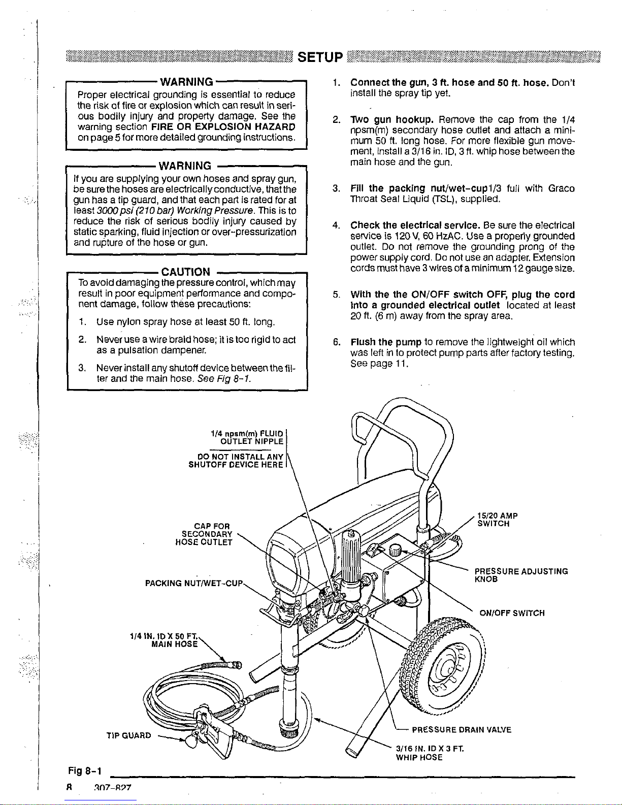
1/4
npsm(m)
FLUID
OUTLET NIPPLE
SHUTOFF DEVICE HERE
00
NOT INSTALL ANY
\
1.
Connect the gun,
3
ft.
hose
and 50 ft.
hose.
Don't
install the spray tip yet.
2.
Two gun hookup.
Remove the cap from the
1/4
npsm(m) secondary hose outlet and attach a mini-
mum 50
ft. long hose.
For
more flexible gun move-
ment, install a
3/16
in.
ID,
3
ft. whip hose between the
main hose and the gun.
3.
Fill
the packing nut/wet-cupi/3
fuii with Graco
Throat Seal Liquid
(TSL),
supplied.
4.
Check the electrical service.
Be
sure the electrical
sewice is
120
V,
60
HzAC.
Use
a properly grounded
outlet.
Do
not remove the grounding prong of the
power supply cord.
Do
not
use
an adapter. Extension
cords must have
3
wires of a minimum
I2
gauge size.
5.
With the the ON/OFF switch OFF, plug the cord
Into
a
grounded electrlcal outlet
located at least
20
ft.
(6
m)
away from the spray area.
6.
Flush the pump
to remove the lightweight oil which
was
left
in to protect pump parts after factorytesting.
See page
11.
Page 9
i
1
To reducethe risk of serious bodily injury, fluid injection. splashing in the eyes or on the skin, or injury
from moving parts, always follow the Pressure Rellet Procedure Warning on page
2
before checking,
adjusting, cleaning and shutting down the sprayer.
Startup
Always
use
this procedure
to
help ensure the sprayer is
ready
to operate and that you start
it
safely.
1.
For a first time startup, flush the sprayer.
See
page
11.
2.
Close the pressure drain valve.
3. Don't install the spray tip
until
the pump
Is
primed!
4. Put the suction tube into the paint container.
5.
Lower the pressure setting by turning the pressure
adjusting knob all the way counterclockwise.
6.
Disengage the gun safety latch.
rCAUTiON7
to
avoid damaging the pump packings.
Do
not run the sprayer dry for more than 30 seconds
~
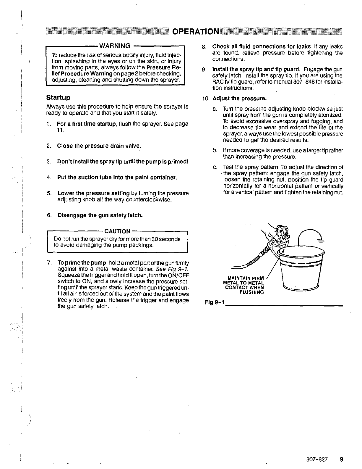
7.
Toprimethepump,holdametaipartofthegunfirmly
against into a metal waste container. See
Fig
9-1.
switch to
ON,
and slowly increase the pressure
set-
Squeeze the trigger and hold
it
open. turn the
ON/OFF
ting until the sprayer starts. Keep the gun triggered until all air is forced
out
of the system and the paint flows
the gun safety latch.
~
freely from the gun. Release the trigger and engage
8. Check all fluid connections for leaks. if any leaks
are found, relieve pressure before tightening the
connections.
9.
Install the spray tip and tlp guard. Engage the gun
safety latch. Install the spray tip. If you are using the
RAC
IV
tip guard, refer
to
manual 307-848 for installa-
tion instructions.
10.
Adjust the pressure.
a.
Turn the pressure adjusting knob clockwise just
until spray from the gun is completely atomized.
To avoid excessive overspray and fogging, and
to
decrease tip wear and extend the life
of
the
sprayer, always
use
the lowest possible pressure
needed
to
get the desired results.
b. If more coverage
is
needed,
use
a largertiprather
than increasing
the
pressure.
c. Test the spray pattern.
To
adjust the direction of
'the spray pattern: engage the gun safety latch,
IOOSen
the
retaining nut, position the tip guard
horizontally for a horizontal pattern or vertically
for a vertical pattern and tighten the retaining nut.
METALTO METAL
CONTACT
WHEN
FLUSHING
MAINTAIN FIRM
/
Fig
9-1
307-827
9
Page 10

Cleaning a Clogged
Tip
WARNING
To reduce the risk of serious bodily injury from from
fluid injection;
DO
NOT hold a hand, body, or rag in front of the
spray tip when cleaning or checking it. Always point
the gun toward the ground or into a waste container
when checking
to
see
if the tip is clear.
DO
NOT try
to
"blow back" paint; this is NOT an air
spray sprayer.
1.
If the spray tip does clog, release the gun trigger, engage the gun safety latch, and rotate the RAC
IV
han-
dle
180".
See
Fig
70-1.
2. Disengage the gun safety latch and trigger the gun
into a waste container. Engage the gun safety latch
again.
3. Return the handle
to
the original position, disengage
the gun safety latch. and resume spraying.
4. If the tip is still clogged, engage the gun safety latch,
sure drain valve to relieve pressure. Clean the spray
shut
off
and unplug the sprayer, and
open
the pres-
tip as shown in manual 307-848, supplied with the
RAC
IV.
SPRAYING
POSITION.
HANDLE SHOWN IN
GUN SAFETY
ENGAGED
LATCH SHOWN
Fig
10-1
Shutdown and Care
1.
Check the packing nut/wet-cup daily. Relieve the
pressure. Keep the packing nut/wet-cup 1/3 full with
TSL at all times
to help prevent fluid buildup
on
the
pistor! rod and premature wear of packings. Tighten
the packing nut
just
enough to stop leakage. Over-
tightening may cause binding and excessive packing
wear.
Use
a screwdriver and light hammer to adjust
the nut.
See
Fig
70-2.
2. Clean the fluid filter often and whenever the sprayer
for the cleaning procedure.
is stored. First relieve pressure.
See
manual 307-273
3. Fill the connecting rod cavity with motor oil every
100
hours of operation. Relieve pressure. Remove
the front cover. See
Fig
10-2.
FILLCONNECTING ROD
CAVITY WITH MOTOR
OIL AFTER
EVERY
100
HOURS
OF
OPERATION
Fig
10-2
4. For very short shutoff perlods, leave the suction
tube in the paint, relieve pressure, and clean the
spray tip.
5.
Coil the hose and hang It
on
the hose rack when
from kinking, abrasion, coupling damage, etc.
storing it, even for overnight,
to
help protect the hose
Page 11

I
When to
Flush
1,
New Sprayer. The sprayer was factory tested
in
light-
weight oil which was left in to protect pump parts.
Before using water-base paint, flush with mineral
spirits, then warm, soapywater, and then clean water.
Before usingoi/-basepaint, flushwith mineral spirits.
2.
Changing Colors. Flush with a compatible solvent.
3.
Changing from water-base to oil-base paint.
Flush with warm, soapy water, then mineral spirits.
5.
Storage. Flush as indicated below, shut
off
the
sprayer, open the pressure drain valve to relieve
pressure and leave it open.
Water-base paint; flush with water, then mineral spirits. Leave the system filled with mineral spirits.
Oil-base
paint:
flush with mineral spirits
CAUTION
NEVER
allow water to freeze
in
the pressure control.
Doing sopreventsthe sprayerfrom being startedand
causes serious damage to the pressure
COfltrOi.
Push the water out with mineral spirits.
6. Startup after storage. Before using water-base
4.
Changing
from
oil-base to water-base paint.
paint, flush out mineral spirits with soapy water and
Flush with mineral spirits, then warm, soapy water,
then clean water. When using oil-base paint, flushout
and then clean water. the mineral spirits with the paint to be sprayed.
How
to
Flush
1.
Relieve pressure.
2.
Remove the filter bowl and screen;
see
manual
307-273. Clean the screen separately and install the
bowl without the screen to flush it. See
Fig
11-1.
PRESSURE
DRAIN VALVE
Fig
11
-1
3.
Close the pressure drain valve.
4.
Pour one-haif gallon of compatible solvent into a
grounded metal pail. Put the suction tube
in
the pail.
5.
Remove the spray tip from the gun, if it
is
installed.
6.
Turn the pressure adjusting knob all the way counter-
r-wARN'NG
1
clockwise to lower the pressure setting.
To
reduce the risk
of
static sparking and splashing
when flushing, always remove the spray tip from the
gun, and hold a metal part of the gun firmly to the
side of grounded metal pail.
7. Hold a metal part of the gun firmly against a metal
turn on the sprayer, and slowly increase the pressure
waste container. See
Fig
11-2. Hold the trigger open,
til
all air is forced out of the system and the solvent
just until the sprayer starts. Keep the gun triggered un-
flowsfreeiy from the
gun.
Release the trigger and en-
gage the gun safety latch..
NOTE lfthe pump
Is
hard to prime, place a container un-
fluid comes from the valve, close
it.
Proceed as
der the pressure drain valve and open it. When
in Step 7.
8.
Remove the suction tube from
the
pail. Disengagethe
gun safety latch and trigger the gun to force solvent
from the hose.
Do
not run the pump dry for more than
30
seconds to avoid damaging the pump packings!
Relieve pressure.
9.
Leave the pressure drain valve open until you are
ready
to use the sprayer again.
If
the screen was removed, unscrewthe filter bowl and reinstall the clean
screen. Reinstall the bowl, hand tight only.
IO.
If you flushed with mineral spirits and are going to
use
a water-base paint, flush with soapy water and then
clean water. Relieve pressure.
MAINTAIN
FIRM'
,
CONTACT WHEN
METAL
TO
METAL
FLUSHING
Fig
11
-2
307-827 11
Page 12

.+i
I:.
. ..
..
.
..
..
,.
~.
..
I
WARNING
Pressure Relief Procedure
To reduce the risk of serious bodily injury, including 6. Open the pressure drain valve, having a container
the eyes or on the skin, moving parts or electric shock,
fluid injection, injury from splashing fluid or solvent in ready
to
catch the drainage. Leave the pressure
drain valve open until you are ready to spray again.
spray system, when installing, cleaning or changing
sprayer'
when
checking
Or
any
part
Of
the
clogged,
orthatpressurehasflotbeenfu//yrelievedaf-
spray tips, and whenever you stop spraying.
terfollowiflg
the
steps above, wrap a rag around the tip
1. Engage the gun safety latch.
guard retaining nut or hose end coupling and VERY
2. Turn the ON/OFF switch
to
OFF.
SLOWLY loosen the pari
to relieve pressure gradually,
3.
Unplug the power supply cord.
then
loosen
completely. Now clear the tip or hose
4.
Disengage the gun safety latch. Hold a metal part
obstruction.
the gun
to
relieve pressure.
of the gun firmly
to a grounded metal pail. Trigger
5.
Engage the gun safety latch.
follow
this
procedure
You
shut
Off
the
/f
you
suspect that the spray
tip
or
hose
is
Check everything
in
the guide before disassembling the sprayer.
TYPE
OF
PROBLEM
If
check
is
OK,
go
to
next check
WHAT TO CHECK
When check
is
not
OK
fefer
to
this
column
WHAT TO
DO
Sprayer will not run
Reset
building circuit breaker; replace Check. electrical supply with volt meter.
Meter should read
105-125
VAC. building fuse. Try another
outlet.
Check extension cord for visible damage.
Use
a volt meter or
test
lamp at
ex-
Replace extension cord.
tension cord
outlet
to
check.
Check sprayer power supply cord forvis- Replace power supply cord.
or wires.
ible damage such as broken insulation
Poor spray pattern
Check for worn spray tip.
~
Relieve pressure and then replace the
tip.
See
the separate gun or tip manual.
Low output
Replace cord with a correct size,
Check extension cord size, which must
have at least 12 gauge wire.
grounded extension cord.
I
I
Motor runs and pump strokes Check for clogged intake strainer. Remove and clean strainer and reinstall.
Check for
loose
suction
tube
or
loose
Building circuit breaker opens
tape on threads, if necessary.
fittings.
Tighten; use thread sealant or sealing
Replace any damaged wiring.
Check all electrical wiring for damaged
insulation.
the
circuit.
Check for other electrical appliances on
position.
High) amp switch.
Put the switch inthe
15
(Lo) amp Check the position of the 15-20 (Lo-
Shutdown other electrical appliances
on the circuit.
Page 13

i
NOTE:
Replace the brushes when they have worn to
brushes wear differently on each side of the
mo-
less
than
1/2
in. See
STEP
1, Fig 13-3. The
tor,
so
check them both and replace both at the
same time. Brush Repair Kit
220-853
is
available.
WARNING
page
12
to
reduce the risk of a fluid injection injury,
Follow the Pressure Relief Procedure Warnlng on
splashing in the eyes or
on
the skin, injury from
moving parts, or electric shock.
SPRING
,
I
Flg
13-2
1.
Remove the motor cover (14) and both inspection
covers
(A).
See Fig 13-1.
2.
Pushinthespringcliptounhookit,andthenpullitout.
See
Fig 13-2.
3. Loosen the terminal screw. Pull the brush lead away,
leaving the motor lead in place. Remove the brush
and spring.
See
Fig 13-3.
4. Inspect the commutator for excessive pitting, burning
or gouging.
A
black color on the commutator is nor-
motor. repair shop if the brushes seem
lo
wear too
mal. Have the commutator resurfaced by a qualified
fast.
5.
Install the new brush
so
its lead is
in
the long slot
of
the holder. Slide theterminal underthe terminal screw
washer. Make sure the motor lead
is
still connected
the at the screw. Tighten the screw. See Fig 13-4.
6.
Place the spring on the brush as shown
in
Fig 13-4.
7.
Push
in
and hook the spring clip. See Fig 13-4.
8.
Repeat for the other side.
ICAUTioN7
Do
not run the sprayer dry for morethan
30
seconds
while checking the brushes
to avoid damaging the
displacement pumD.
9.
Reinstall the remaining parts.
2
SPRING CLIP
BRUSH
LEAD
TERMINALSCREW
MOTOR TERMINAL
Fig
13-3
,
BRUSH
HOLDER
SHORT SLOT
'/
Fig
13-4
NOTE: SPRING MUST COIL
IN THIS DIRECTION
I
.
,'
307-827
13
Page 14

..
WARNING
Follow the Pressure Relief Procedure Warning on
page 12 to reduce the risk of a fluid injection injury,
moving parts,
or
electric shock.
splashing
in
the eyes or on the skin, injury from
1. Disconnect the hose (47).
2. Loosen the filter bracket
nut
(28). Remove the fluid
filter.
3.
Remove the pressure control cover (36). Disconnect
the four motor leads.
4. Unscrew the connector (54). Pull the wires out of the
pressure control.
5.
Remove the pressure control mounting screws
(37).
Remove the pressure control.
Remove
the back plate
(1
6).
6.
Install the new pressure control.
1. Remove the back pressure control piate (16).
2. Remove the pressure control cover. Disconnect the
3.
Loosen the strain relief bushing (E). Remove the
4. Install the new cord.
power supply cord leads.
power supply cord (43a).
Fig
14-2
BACKVIEW
OF
PRESSURE CONTROL
Page 15

~~
1
I
I
!
j
i
!
~~~~~~~~~~:
:I
,.a2aBei%:&
REMOVING AND INSTALLING THE DISPLACEMENT PUMP ~~~~~~~~~~
Removal
See
Fig
15-1.
I.
Flush the pump, if possible, and relieve pressure
again. Stop the pump with the piston rod in its lowest
position, if possible.
2.
Remove the suction tube
(42);
hold the wrench on
the pump intake valve
(223)
to
keep the pump from
loosening.
3.
Remove
the
hose
(47).
4.
Push the retaining spring
(35)
up and push out the pin
(20).
5.
Loosen the locknut
(38)
and unscrew the pump from
the bearing housing
(27).
Installation
See
Fig
15-1
and
75-2.
1.
Screw the displacement pump into the bearing hous-
bly
(29)
and the displacement rod
(224)
align. Install
ing
(27)
until the pin hole in the connecting rod assem-
the pin
(20).
2.
Continue to screw the pump into the bearing housing
with the face of the bearing housing and the
outlet
nip-
until
Ihe
top threads
of
the pump cylinder are flush
ple
(75)
is straight back. Push the retaining spring
(35)
Tighten the locknut
(38)
to
70
ff-lb
(97
N.m).
into
the
groove all theway around the connecting rod.
WARNING
groove of the connecting rod, all the way around, to
Be
sure the retaining spring
(35)
is firmly
in the
prevent it from working
loose
due
to
vibration.
off
due
to the force of the pumping action. These
If the pin works loose, it or other parts could break
parts could be projected through the air and result in
serious bodily injury or property damage, including
damage
to
the pump, connecting rod or bearing
housing.
r-cAUT'oN"l
If
the locknut
(38)
loosens during operation, the
threads of the bearing housing
(29)
will
be
dam-
aged. Be sure
to
tighten the locknut firmly.
w..\
223
b42
Fig
15-1
I1
Fig
15-2
!
3.
Tighten the packing
nut/
wet-cup
just
enough to stop
leakage, but no tighter. Fill the wet-cup/packing nul
1/3
full
with Graco TSL.
307-827
15
Page 16

i
'
I
i
I
:
j
I
~~~~~~~~~~~~,~~~~~~~,
WARNING
Follow the Pressure Rellef Procedure Warnlng
6.
Remove the sleeve. Use
on page
12to
reduce the risk of afluid injection inju-
the sleeve removal tool,
part
no.
220-991,
if neces-
ry,
splashing
in
the eyes or
on
the skin, injury from sary.
moving parts
or
electric shock.
To use the tool: screw the
NOTE:
Packing Repair Kit
222-877
is available. Parts
in-
thetop of the cylinder
(19).
large nut
(E)
of
the tool into
cluded in the kit are marked with an asterisk
(*)
in the text. Use all the new parts
in
the kit. Clean
Screw down the rod
(D)
to
push the sleeve out. Reall parts. Inspect the non-kit parts for wear or move the tool. See Fig
damage, and replace them as needed.
16-3.
7.
Clamp the piston rod
(224)
in
a vise. Loosen the jam
nut
(21 1).
Unscrew the pis-
ton valve
(222).
Flg
16-3
8.
Remove all parts from the piston valve
(222).
223
Flg
16-1
Reassembling the
Pump
NOTE:
Alternate leather and plastic packings. The lips
of the throat
"v"
packings must face down.The
lips of the piston
"V"
packings must face
up.
The
lips of the U-cup seal
(203)
face down. Incorrect
installation damages the packings and results in
pump leaking.
NOTE:
Soak leatherpackings in oil before reassembling
the pump.
1.
Check the outside of the piston rod
(224)
and the in-
new packings will
not
seal properly. Replace these
side of the sleeve
(21
8)
for wear. if the parts are worn,
parts if needed.
LIPS
OF
V-PACKINGS
MUST
FACE
DOWN
2.
Stack these parts onto the piston valve
(222):
the
backup washer
(214),
seal
(203*),
female gland
(215*),
alternate the three plastic packings
(212*)
gland
(210*).
Flg
16-2
and the
two
leather packings
(206*),
and the male
Disassembling
the
Pump
3.
Tighten the packingretainingnut
(21
1)
ontothepiston
1.
Remove the intake valve
(223),
O-ring
(202),
ball
guide
(220),
stop
pin
(221)
and ball
(204).
Clean the
valve
(222)
to 4 in-lb
(0.35
Nm). See Fig
17-2.
parts.
See
Fig
16-1.
4.
Place the ball
(225)
on
the piston valve
(222).
2.
Always install anewo-ring
(202*).
Ifnofurther sewice
5.
Apply
One
drop
Of
supplied, to the Piston
is needed, reassemble the intake valve. valve threads. Hand tighten the valve assembly into
the piston rod just until the nut
(21
1)
contacts the rod.
3.
Remove the packing nut
(21 6)
and plug
(205).
See
Fig Note the alignment of the piston
(222)
to
the nut
16-2. (21 l),
and maintain it through Steps
5,
6
and
7.
Use
two
wrenches to maintain the alignment,
4.
Tap the piston rod
(224)
down with a plastic mallet,
and then pull the rod
out
the bottom of the cylinder. 6.
'lace
the
flats
at
the top
Of
the
rod
in
a
5.
Remove the throat packings
(207,
213)
and glands
7.
Use a wrench to
CAREFULLY
tighten the ]am nut
(21
1)
onto the piston rod to
19
lt-lb
(25
N.m). See Fig
lfi
1n7-~37
(208, 209).
See
Fig
16-2.
17-3.
Page 17

..
.
i
8.
Place a new seal (217*) into the cylinder. See Fig
17-1,
9.
Install these parts in the top of the cylinder (219): the
male gland
(208*), alternate the three plastic pack-
then install the female gland
(9).
See
Fig 17-1.
ings (21
3')
and the
two
leather packings
(207*),
and
10.
Loosely install the packing nut (216) and plug
(205).
See
Fig 17-1.
11. Coat the piston rod and packings with oil. Carefully
slide the assembly
Into the
top
of
the sleeve.
12. Slide the sieeve/piston rod assembly
Into the bot-
tom
of the cylinder.
See
Fig 17-4.
13. Screw down the cylinder locknut (47) until it
is
finger
tight at the bottom of the external cylinder threads.
14. Placethe intakevalve
(223)
in avise. Install a new
o-
ring (202*). Screw the pump cylinder into the intake
valve.
Torque to 110 R-lb (146
Nm).
See Fig 17-1,
15.
See
page 15 to reinstall the pump.
.:
4
In
TOROUE TO
21 1
-Ib
(0.35
Nm)
~
Fig
17-2
ADHESIVE TO PISTON
APPLY ONE DROP
OF
VALVE THREADS
II
21
1
TOROUE ROD ONTO JAM
NUT-PISTON ASSEMBLY
TO
19
R-lb
(27
N.m)
DO NOT ALLOW NUT ON
WHEN SCREWING INTO
ROD
PISTON VALVE TO MOVE
Fig
17-3
224
ROD
-
,CYLINDER
SLEEVE
ASSEMBLY
PISTON
Fig
17-4
Page 18

..
WARNING
page 12 to reduce the risk
of
a fluid injection injury,
splashing
in
the
eyes
or
in the skin,
injury
from mov-
ing parts or electric shock.
1. Remove the motor shield (14). Remove the front
cover (32). Disconnect the hose (47).
2. Remove the pressure control cover (36). Disconnect
the four motor leads.
3. Unscrew the connector (54) from the pressure con-
trol.
Pull
the wires through the connector.
4.
Unscrew the connector (54) from the motor and re-
move it from the conduit
'(22).
5.
Remove the screws
(51)
from the recess of the drive
housing.
6. Remove the screws
(21
and 30) from the the motor
bell
(F).
7.
Use a plastic mallet
to
tap the displacement pump
(39) from the rear
to loosen
the
drive housing
(1
8)
from
the motor bell
(F).
Pull
off
the
drive housing.
NOTE:
To
avoid damage
to
the
drive housing:
engaged
in
the motor bell or inthe drive housing.
Do
not
drop the gear cluster
(9),
which may stay
Do
not
lose
the thrust balls
(1
0) or drop them be-
~eengears.Theballsusuallystayintheshaftre-
not in place, the bearings will wear prematurely.
cesses, but could be dislodged. If the balls are
8.
Remove the screws
(8)
holding the motor
to
the
frame. Lin
off
the motor.
9.
Mount the new motor
on
the frame.
10. Slide a connector (54) over the conduit (22) ofthe new
motor and screw
two
or three threads
of
it into the mo-
tor. Tighten the locknut (44) up to the motor.
11. Liberally grease the gear cluster (51) and pinion gear
(G)
and pack all bearings
in
the motor bell.
Be
sure
the
thrust balls (9) are
in
place.
(One
ball is included
with a replacement motor.)
12. Place the bronze-colored washer
(18b)
and THEN
the silver-colored washer (18a)
on
the shaft protrud-
ing from
the
big gear in the drive housing (18).
13. Align the gears and push the drive housing (18)
straight onto the motor bell
(F)
and locating pins.
14. Continue
to
reassemble the sprayer.
Page 19

:.
,
..
!
i
1'
I
.,
i
MOTOR
LEAD
BLACK(-)
BLACWWHITE
(+)
MOTOR
LEAD
\
MOTOR
RED
LEADS
/
I
307-827
19
Page 20

rWAIINING
1
~~~?~~~~~~~~~
~~~~?~~~~~~~~~~~~~
BEARING HOUSING & CONNECTING
ROD
REPLACEMENT
~~~,~~,~~
NOTE:
Stop the sprayer at the bottom of its stroke to get
Follow the Pressure Relief Procedure Warning on the crank
(H)
in
its lowest position.To lower the
page 12 to reduce the risk
of
a fluid injection
injury,
crankmanually. rotatethe blades
of
the rnotorfan
splashing
in
the eyes or in the skin, injury from mov- with a screwdriver.
1
ing parts-or electiic shock.
..
1. Remove the pump.
See
page
15,
2.
Remove the front cover (31). Remove the bearing
housing screws (33).
\
3.
4.
5.
6.
7.
8.
9.
Tap the lower rear of the bearing housing (27) with a
plastic mallet
to
loosen it
from
the drive housing
(1
8).
Pull
the bearing housing and the connecting rod (29)
straight
off
the drive housing.
Remove the pail bracket assembly (L) and reinstall
it
on
the new bearing housing.
Inspect the crank
(H)
for excessive wear and replace
parts as needed.
Evenly lubricate the inside
of
the bronze bearing
(K)
withmotoroil. Liberallypackthe roller bearing
(J)
with
bearing grease.
Assemble the connecting rod (29) and bearing hous-
ing (27).
Clean the mating surfaces
of
the bearing and drive
housings.
Align the connecting
rod
with the crank
(H)
and align
the locating pins in the drive housing with the holes
onto the drive housing or tap
it
into place with a plas-
in the bearing housing (27). Push the bearing housing
tic mallet.
1
10. Install the bearing housing screws (33). Torque even-
I
Fig
20-1
ly to
175
in-lb (19 N.m).
11. Reinstall all parts. See page15
to
install the pump.
!
..
I
!
.
..
~
.
-..,
.i
:.;;
i
:
!
..
I
20
307-827
Page 21

. ..
'.
j
!
I
..
.,
,
.. .
..
..
:.:
.::.
.
.
. . .
.
....
.
,
i'
..
. ... ..
,
.,.. , .
,~.
,
.~
..
~
.
.. . .
:
,:
...
.,.
....
,
..
page
12
to reduce the risk of afluid injection injury,
Follow the
Pressure Relief Procedure
Warning on
splashing
in
the eyes or
in
the skin, injury from mov-
ing parts
or
electric shock.
See
Fig
21-1.
NOTE
Stop
the sprayer at the bottom of its stroke to get
the crank
(H)
in its lowest position. To lower it
with a screwdriver.
manually, carefully rotate the blades
of
the fan
1. Remove the front cover
(32).
Remove the motor
shield (14).
2.
Disconnect the pump outlet hose (47).
3.
Remove the screws
(33)
from the bearing housing.
4.
Lightly tap the lower rear
of
the bearing housing (27)
with a plastic mallet to loosen it from the drive hous-
ing
(18).
Pull
the bearing housing and connecting rod
assembly straight
off
the drive housing.
5.
Remove the screws (51) from the recess of the drive
housing.
6.
Remove the screws
(30
and 21) from the motor bell
(F).
7.
Tap the drive housing (18) with a plastic mallet to
loosen it from the motor bell. then pull
it
straight
off.
NOTE:
To avoid damage to the drive housing:
Do not drop the gear cluster (9), which may stay
engaged in the motor bell or
in
the drive housing.
Do not lose the thrust balls (10) or drop them be-
tween gears.
The
balls usually stay inthe shaft
re-
not
in
place, the bearings will wear prematurely.
cesses, but could be dislodged. If the balls
are
8.
Use
approximately
6
02.
of the bearing grease
supplied with the drive housing replacement kit to
grease the gear cluster (9). Checkto be sure thethrust
balls (10) are in place.
9.
Place the bronze-colored washer (18b) and.THEN
the silver-colored wastier (18a) on the shaft protrud-
ing from the big gear in the drive housing (18).
IO.
Align the gears and push the new drive housing
straight onto the motor bell and locating pins.
11. Continue to reassemble the sprayer. Torque the
screws
(33)
to
175 in-lb (19 N.m).
307-827
21
Page 22

Page 23

~~~~~~~~~~~~~~
PARTS DRAWING - BASIC SPRAYER
~~~~,~~~~~~~~~~~~~
,iii
..,.
..,....,....
x.~<~,.~"'..':.?
,,,^n~,:,.W*~~~.,:.~~~,~..~.~~~~:~~~~
Ultra
1500
Sprayers with Upright Cart
Model
220-627,
Series
A
Model
231-053
Includes
items
1-91
Includes
items
1
-
91,
100 - 102
Basic
Sprayer
Complete Sprayer
*,z<*~>j*>.:<,:<w
.,...,,,,,
r^,l"
......
""'':'%>>.:.:.:
.,.., ~
REF
NO. PART NO. DESCRIPTION
QTY
NO. PART NO. DESCRIPTION
QTY
1
220-854
2 183-196 LABEL, identification, motor cover
1
MOTOR KIT
1
51 108-849 CAPSCREW, sch: 1/4-20 x 3" 2
3 183-197 LABEL, identification, motor cover 1
52 110-243 RING, retaining
53 108-691 PLUG, tubing
2
4 183-198 LABEL. identification, front cover
1
54 110-309 CONNECTOR
2
6 220-636
CART
1
55
172-981' LABEL. WARNING
1
7 181-072
STRAINER
1
56
102-556
RIVET,
blind 0.125" dia.
2
8
155-665 UNION, adapter;
3/8"
npsmswivei 57 178-034' TAG, WARNING
2
1
9 220-637 GEAR REDUCER
1
1
58
101-242 RING, retaining
59 206-994 THROAT SEAL LIQUID
2
10 100-069 BALL. steel; 1/4" dia.
11 104-811 HUBCAP
1
2 60 179-811
8
02.
(0.27 liter)
1
12 220-285 CAP
WHEEL
1
61 220-633
HANDLE. CART
2
1
REF
x
3/8
npt(m)
i
13 100-322 LOCKWASHER. ea., shakeproof,
62 183-194
SLEEVE,^^^^
handle 2
14 223-153
MOTOR
SHIELD KIT
1
~1
63 105-510 LOCKWASHER, spring, 1/4"
6
64 108-865 SCREW, mach. pnh: 8-32 x ,375" ' 10
15 110-037 SCREW, mach, pnh: 10-24 type C
x
69 108-662 NUT, retainer 2
16 185-539 BRACKET, mounting
1
75 183-461 ADAPTER;
3/8
npsm x 1/4 npt
1
17 179-777 BUTTON. snao 2 77 181-608* LABEL.WARNlNG
2
1
7/16"
OS"
4 71 177-762* LABEL, WARNING
18
19
20
21
22
23
24
26
27
220-879
183-037
183-210
DRIVE
HOUSING
KIT
1
HANGER, pail
1
PIN, straight,
3/8
x
1.125" 1
SCREW, socket head, no. 1/4-20 x
.75" 2
CONDUIT, electrical
specify length when ordering 14
in.
POWER SUPPLY CORD
1
78
80
79
81
82
176-250'
107-194
4
1
109-032
185-384
110-240
3
2
2
2
100-644
070-487
223-109
154-636
107-264
220-639
NUT
a3
84
183-350
106-078
110-324
185-565
100-035
WASHER, flat;
7/8"
ID
SCREW. flat hd: 10-24
x
,375"
87
LABEL, control
BUSHING. strain relief
SCREW. mach. onh 8-32
x
.312"
TERMINAL, female
WASHER
BEARING HOUSING KIT
~~
2
1
1
i8
89
.
~~
inside pressure confroi
LOCKWASHER, internal. No.
8
inside pressure control
LOCKWASHER, ,194" ID
cpld 1/4 npsm(f); 50
ft
(15 m);
HOSE,
gorunded. nylon; 114" ID;
spring guards both
ends
cpld 1/4 npsm(f); 3
ft.
(9 m);
HOSE,
grounded, nylon; 3/16"
ID;
spring guards both ends
SPRAY GUN
see
manual
307-614
for
pads
28
29
30
31
32
220-640
150-513 NUT, jam; 7/16"
CONNECTING
ROD
KIT
1
1
90
91
100
157-021
100-020
210-541
100-643
183-168
108-850
110-141
179-945
SCREW, socket head, no. 1/4-20
x
1" 2
COVER, housing
SCREW, mach, fiih; no. 8-32
x
1.25" 4
1
CAPSCREW, Sch; 3/8-16 x 1.5" 4
ADAPTER, elbow, special;
SPRING, retaining
1/4-18 npt(m
x
r)
1
COVER, pressure control
1
CAPSCREW,
hex
head, 5/16-18 x .75 7
1
NUT,
HEX,
1
13/16
unc-2b
1
DISPLACEMENT PUMP
33
34
1
101 214-701
35
36
183-169
185-000
100-057
183-170
37
38
39
40
41
42
43
43a
44
46
47
48
102
220-955
220-872
100-214
100-188
183-423
223-152
223-109
107-190
162-453
220-849
214-570
seepamonpage24
LOCKWASHER, spring; 5/16"
NUT, heavy hex: 5/16-18 unc-2a
TUBE, INTAKE
PRESSURE CONTROL KIT
lncludcr
IopIacanbIe
Item
43a
and
one
of
Item
.POWER SUPPLY CORD
LOCKRING
NIPPLE, hex; 1/4 npsm
x
1/4 npt,
HOSE, 318 npsrn(f)
x
14.5"
1-3/16" long
FLUID FILTER
see manual
307-273
for
parts
includes one
of
item
75
1
7
7
1
w1
1
1
1
1
'Extra warning tags and labels available free.
I
!
i
.
.,
I
i
1
LOCKWASHER,
spring;
318"
4
PRESSURE DRAIN VALVE
1
49
50
222-198
106-115
I
307-827
23
Page 24

..
,
..
..
.
.... .
':
Model
220-872,
Series
A
Displacement Pump
Includes
items 202
10
225
REF
NO.
PART
NO.
202 107-098*
203 168-696*
204 108-775'
205 183-171
206 183.174'
207 183-175*
208 183-176'
209 183-177'
210 183-178'
211 183-179
212 183-182'
213 183-183*
214 183-184*
~ ~~
215 183-185*
217 183-172+
216 183-186
218 183-361
219 183-181
220 183-180
221 183-173'
222 220-631
223 220-629
224 220-630
225 101-947*
DESCRIPTION
QN
SEAL, sleeve
1
SEAL, u-cup. polyurethane
1
BALL: sst 1
PLUG
V-PACKING, leather
V-PACKING. leather
GLAND. male
GLAND, female
GLAND, male
V-PACKING, plastic
NUT, hex, retaining
V-PACKING. plastic
WASHER, backup
GLAND, female
O-RING,
NUT, packing
SLEEVE, cylinder
CYLlNDER
1
2
2
1
1
1
1
3
3
1
1
1
1
1
1
GUIDE, bail
1
VALVE, piston
PIN, ball stop
1
VALVE, Intake
1
ROD, piston
1
BALL
1
1
*Supplied
in
repair kit 220-877.
SLEEVE REMOVAL TOOL
220-991
Use
to
remove a sleeve that
is
stuck.
Purchase separately.
*207
5208*
05
202'
0
223
PTFE
Page 25

MOTOR
BRUSH KIT 220-853 SUCTION TUBE KIT 208-920
5
gallon
(19
liter)
size
Includes:
DISPLACEMENT PUMP PACKING KIT 220-877
REF
NO.
PART NO. DESCRIPTION
See
contents
on
page
24.
SUCTION TUBE KIT 208-259
55
gallon
(200
liter)
size
Includes:
REF
NO. PART NO.
2 214-961
1 156-589
3
156-591
4 156-593
5 100-220
6 176-684
7 156-592
8
159-100
9 161-377
10 159-101
DESCRIPTION
ON
UNION,
90°;3/4
npt(0
X
3/4
npt(f)
SW
1
6
R
(1.8
rn);
spring guard
one
end
1
HOSE,
cpid
314
npt(rnbe);
314"
ID;
nylon;
ELBOW,
goo;
314
npt
x
1-1/2 - 24
ns
1
PACKING,
O-ring,
nitrile
1
ADAPTER,
bung
TUBE, riser
1
1
RETAINER.
screen
1
THUMBSCREW,
5/16-18 X 1"
SCREEN,
filter
NUT, sceen retainer
1
1
101418
CLAMF
hose
160-327
UNION,
90'
swivel;
3/4
npt(m
x
fl
170-705
ADAPTER, Intake
170-706
HOSE,
1"
ID
x
48";
nylon
170-957
TUBE, suction
181-072
STRAINER
an
1
1
1
1
1
1'
307-1327
25
Page 26

I
>..
...
i
.,
..
.~.
.
....
..
.
:
!
.,.~
......
.....
.:.
.
...
I
:
'
''1
...
..
,.
.,.,.
1
:
'.
~
s:..
,,
.,
..
~
.. , .
...
..........
.
.!
......
. : .
~~,~~~~~~~~~
TECHNICAL DATA
~~~~~~~~~
dG..sl
.,.,.
~~.,~"'''''~'
,.3:$,:<?."<;mA
.....
~,,d
Power Requirements
(full
output)
.....
120 VAC,
60Hz,
1
phase,
18
amp minimum
Working Pressure Range
....
0-3000 psi
(0
-
210 bar)
Cycles/Gailon (liter) .................... 104 (27.5)
Power Cord
..........
No.
12 AWG. 3 wire,
10
(3
m)
Inlet Paint Strainer
...........
I6
mesh
(1
190
micron)
Stainless
Steel
Screen, reusable
Outlet Paint Filter
.............
60 mesh (250 micron)
Stainless
Steel
Screen, reusable
Pump Inlet Size
.......................
3/4 npt(m)
Wetted Parts:
Fluid
Outlet
Size
1/4
npsm from
fluid
filter
Displacement
Pump
... Carbon
steel,
Polyurethane,
polyethylene, DelrinB, Leather
Filter
.....
Aluminum, Carbon
steel,
Stainless Steel,
NOTE:
DeirinB is a registered trademark
of
the
...........
Company,
26
307-827
Weight
(w/o
packaging)
............
122
Ib
(55.5
kg)
Height
...........................
32 in. (813 mm)
Length
.......................
24.25 in. (616 mm)
Width
.........................
22.5
in.
(572
mm)
Page 27

'.
:
j
..
... , .
.!
.. .
Page 28

WARRANTY
Graco warrants all equipment manufactured by it and bearing its name
to
be free from defects in material and
workmanship
on
the date of sale by an authorized Graco distributorto the original purchaser for
use.
As
pur-
chaser's
sole
remedy for breach of this warranty, Graco will, for a period of twelve months from the date of
sale. repair orreplace any part of the equipment proven defective, with the exception of defects in parts
on
the
drive train/gear box
on
EM and GM sprayers or power train
on
EH & GH
sprayers, which will be repaired or
replaced for twenty-four months from the date of sale for Gas-Hydraulic (GH) and
Gas Mechanical (GM) sprayers and for thirty-six months from the date of sale for Electric-Mechanical (EM)
and Electric-Hydraulic
(EH) Sprayers. This warranty applies only when the equipment is installed, operated
and maintained in accordance with Graco's written recommendations.
This warranty does
not
cover, and Graco shall not
be
liable for, any malfunction, damage or wear caused by
faulty installation, misapplication, abrasion, corrosion, inadequate or improper maintenance, negligence,
accident, tampering, or substitution of non-Graco component parts.
Nor
shall Graco be liable for malfunc-
tion, damage or wear caused bythe incompatibilitywith Graco equipment
of
structures, accessories, equip-
ment or materials not supplied by Graco, or the improper design, manufacture, instaliation, operation or main-
tenance of structures, accessories, equipment or materials
not
supplied by Graco.
This warranty
is
conditioned upon the prepaid return of the equipment claimed to be defective to an author-
ized Graco distributor for verification of the claim. If the claimed defect is verified, Graco will repair or replace
free of charge any defective parts. The equipment will be,returned
to the original purchaser transp.ortation
repaid. If inspection of the equipment does not disclose any defect.in material or workmanship, repairs will
e
made at a reasonable charge, which charges may include the costs of parts, labor and transportation.
1
DlSCLAiMERS AND LiMlTATlONS
THETERMSOFTHISWARRANTY'CONSTlTUTEPURCHASER'SSOLEANDEXCLUSlVEREMEDYANDAREINLIEUOFANYOTHER
WARRANTIES fEXPRESSOR IMPLIED). INCLUDINGWARRANTY'OF
MERCHANTABILITYORWARRANTYOFFITNESSFORAPAR-
TICULAR
PURPOSE,
AND
OF
ANY
NON-CONTRACTUAL
LIABILITIES.
INCLUDING
PRODUCT
LIABILITIES.
BASED
ON
NEGLI-
GENCE
OR
STRICT LIABILITY. EVERY FORM OF LIABILITY FOR DIRECT SPECIAL
OR
CONSEQUENTIAL DAMAGES
OR
LOSS
IS
EXPRESSLY EXCLUDED AN0 DENIED. IN NO CASE SHALL GRACO'S LIABILITY EXCEED THE AMOUNT
OF
THE PURCHASE
PRICE. ANY ACTION FOR BREACH OF WARRANTY MUST BE BROUGHT WITHIN
TWO
(2)
YEARS OF THE DATE
OF
SALE.
EQUIPMENT NOT COVERED
BY
GRACO WARRANTY
TICULAR PURPOSE, WITH RESPECT
TO ACCESSORIES, EQUIPMENT. MATERIALS,
OR
COMPONENTS SOLD BUT NOT MANU-
GRACO MAKES NO WARRANTY. AND
DISCLAIMS ALL IMPLIED WARRANTIES
OF
MERCHANTABILITY AND FITNESS
FOR
A
PAR-
FACTURED BY GRACD.TheSe
items Soid, but
not
manufactured by Graco (such as electric motor, switches, hose,
etc.) are subject
to
the warranty, if any, of their manufacturer. Graco will provide purchaser with reasonable
assistance in making any claim for breach of these warranties.
Subsidiary and Affiliate Companies: Canada; England; Switzerland; France;
Germany; Hong Kong; Japan
Factory Branches: Atlanta, Dallas, Detroit,
Los
Angels. West
Caldwell (N.J.)
GRACO INC.
P.0.
BOX
1441 MINNEAPOLIS, MN 55440-1444
PRINTED IN U.S.A.
307-827
5-89
 Loading...