

Page 1

INSTRUCTIONS–P
This manual contains important
warnings and information.
READ AND RETAIN FOR REFERENCE
120 VAC, 15 AMP
ARTS LIST
307–785
Rev J
Supersedes
H
Ultra 1000
3000 psi (210 bar) Maximum Working Pressure
Model 231–034, Series D
This
is a basic sprayer on an upright cart
and does not include a hose or a gun.
Model 231–043, Series B
This
is a complete sprayer on an upright cart and
includes a hose, a gun, a RAC IV DripLess
Guard, and a SwitchT
U.S. PA
PATENTED 1983, CANADA
AND OTHER PATENTS PENDING
TENT NO. 4,323,741; 4,397,610
ip.
Airless Paint Sprayer
Tip
GRACO INC. P.O. BOX 1441
COPYRIGHT
MINNEAPOLIS, MN
1986, GRACO INC.
MODEL 231–043
55440–1441
Page 2
Table
of Contents
Introduction 2.
Warnings 4
Setup 10
Operation 12
Shutdown
Flushing
Troubleshooting
Spin Test 22.
Bridge Test 23.
. . . . . . . . . . . . . . . . . . . . . . . . . . . . . . . . . . .
. . . . . . . . . . . . . . . . . . . . . . . . . . . . . . . . . . . . . .
. . . . . . . . . . . . . . . . . . . . . . . . . . . . . . . . . . . . . . . .
. . . . . . . . . . . . . . . . . . . . . . . . . . . . . . . . . . . .
And Care
Guidelines
Guide
. . . . . . . . . . . . . . . . . . . . . . . . . .
. . . . . . . . . . . . . . . . . . . . . . . . . .
. . . . . . . . . . . . . . . . . . . . . . . .
14.
15.
16.
. . . . . . . . . . . . . . . . . . . . . . . . . . . . . . . .
. . . . . . . . . . . . . . . . . . . . . . . . . . . . . .
Repair
General
Motor
Power
On/Off
Bridge
Circuit
NOTE: This
Repair Information
Brush
. . . . . . . . . . . . . . . . . . . . . . . . . . . . .
Supply Cord
Switch
Rectifier
Breaker
. . . . . . . . . . . . . . . . . . . . . . . . . . . .
. . . . . . . . . . . . . . . . . . . . . . . . . .
. . . . . . . . . . . . . . . . . . . . . . . . . . .
. . . . . . . . . . . . . . . . . . . . . . .
. . . . . . . . . . . . . . . .
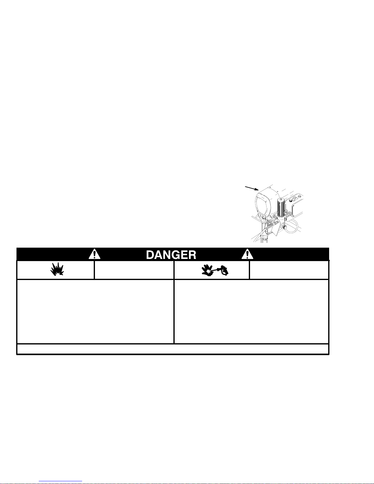
is an example of the DANGER
24.
25.
26.
26.
27.
27.
label on your sprayer. If you have operators
who do not read the English language, order
one of the labels shown to the right. Place the
label on the sprayer in the location shown at A.
The labels are available directly from Graco,
free of charge. Call 1–800–328–021
1.
Circuit
Board
Pressure
Pressure
Bearing
Drive
Motor 34
Housing & Connecting Rod
Housing
. . . . . . . . . . . . . . . . . . . . . . . . . . . . . . . . . . . .
Removing
Displacement
. . . . . . . . . . . . . . . . . . . . . . . . . . . .
Control
Control Adjustment
. . . . . . . . . . . . . . . . . . . . . . . . .
. . . . . . . . . . . . . . .
. . . . . . . . . . . . . . . . . . . . . . . . . . .
and Installing a Pump
Pump
. . . . . . . . . . . . . . . . . . . . . .
. . . . . . . . . . . .
Parts
Sprayer
Pressure
Wiring
Displacement
Technical
Dimensions 47
Graco
Phone Numbers
The
Graco W
. . . . . . . . . . . . . . . . . . . . . . . . . . . . . . . . .
Control
Diagram
Data
. . . . . . . . . . . . . . . . . . . . . . . . .
. . . . . . . . . . . . . . . . . . . . . . . . . . .
Pump
. . . . . . . . . . . . . . . . . . . . . .
. . . . . . . . . . . . . . . . . . . . . . . . . . . . . . .
. . . . . . . . . . . . . . . . . . . . . . . . . . . . . . . . . . .
. . . . . . . . . . . . . . . . . . . . . . . .
arranty and Disclaimers
. . . . . . . . . . .
A
French 185–955
Spanish 185–962
German 186–042
Greek 186–046
Korean 186–050
. . . . . . . . .
01217A
28.
29.
30.
32.
33.
36.
37.
40.
42.
43.
44.
47.
47.
48.
FIRE
AND
EXPLOSION HAZARD
Spray
painting, flushing or cleaning equipment with flammable liq
in confined areas can result in fire or explosion.
uids
Use
outdoors or
hoses, containers and objects being sprayed.
ment,
Avoid all ignition sources such as static electricity from plastic
cloths, open flames such as pilot lights, hot objects such as
drop
cigarettes,
turning
light switches on and off.
Failure
to follow this warning can result in death or serious injury
in extremely well ventilated areas. Ground equip
arcs from connecting or disconnecting
READ AND UNDERSTAND ALL LABELS AND INSTRUCTION MANUALS BEFORE USE
power cords or
SKIN INJECTION
HAZARD
Liquids can be injected into the body by high pressure airless
-
-
.
or leaks – especially hose leaks.
spray
Keep
body clear of the nozzle. Never stop leaks with any part of the
body.
Drain
triggering
Never
In case of accidental skin injection, seek immediate “Surgical
Treatment”.
Failure
injury.
all pressure before removing parts. A
of gun by always setting safety latch
spray without a tip guard.
to follow this warning can result in amputation or serious
void accidental
when not spraying.
Page 3
Introduction
Pressure Control
The
pressure control includes an ON/OFF switch for
the sprayer
pressure–sensing device and a current–overload cir
, the pressure–adjusting control knob, a
cuit breaker with a manual–reset button. The pressure
control regulates the motor speed.
Motor
The DC motor has sealed bearings and replaceable
motor brushes. The motor operates whenever there is
a demand for fluid or additional fluid pressure. When
the pump is cycling, the motor sounds like the cranking
of an automobile starter
. When the pump is not cy
cling, the motor hums intermittently until the fluid pres
sure stabilizes, then the motor will shuts of
f. However
,
there is still power to the sprayer and the sprayer stays
pressurized and ready to use until you manually shut it
of
f and relieve the pressure.
The direct–current (DC) motor is less sensitive to low
voltage or voltage fluctuations than an alternating–cur
rent (AC) motor
af
fect the sprayer performance.
. However
, long extension cords may
Drive Assembly
The
drive assembly, which is sealed, transfers power
from the DC motor to the displacement pump.
Displacement Pump
The
displacement pump provides equal fluid delivery
on both the up and the down pump stroke strokes. The
pump has a packing nut which, when filled with Graco
Throat Seal Liquid T(SL), helps prevent damage to the
throat packings and piston rod.
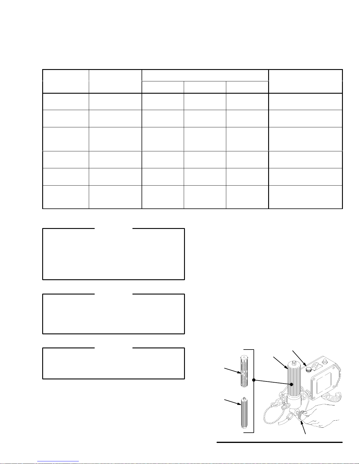
Fluid Filter
The
fluid filter strains the paint to help avoid clogs in
the hose and the spray tip. The filter includes a reus
able element and has a pressure drain valve for manu
-
-
ally relieving fluid pressure.
Hoses
-
-
The grounded, nylon spray hoses have spring guards
on both ends. The 50 foot (15.2 meter) hose has a 1/4
inch ID. The 3 foot (0.9 meter), 3/16 inch ID hose pro
vides more flexible gun movement. The nylon hose
material acts as a pulsation dampener to absorb pres
sure fluctuations.
Spray Gun & RAC IV DripLess Tip Guard
The
spray gun has a trigger safety which prevents ac
cidental triggering when it is locked. The gun has a
filter for final paint–straining. The Reverse-A-Clean IV
(RAC IV) SwitchT
clogs from the spray tip without removing it from the
gun. The RAC IV DripLess tip guard is a safety feature
which helps reduce the risk of a skin injection injury
ip uses high pressure fluid to remove
.
-
-
-
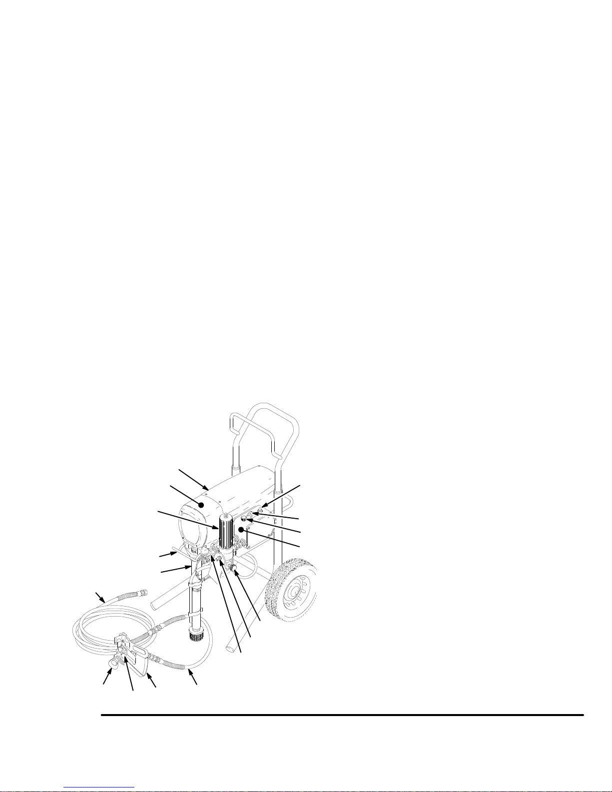
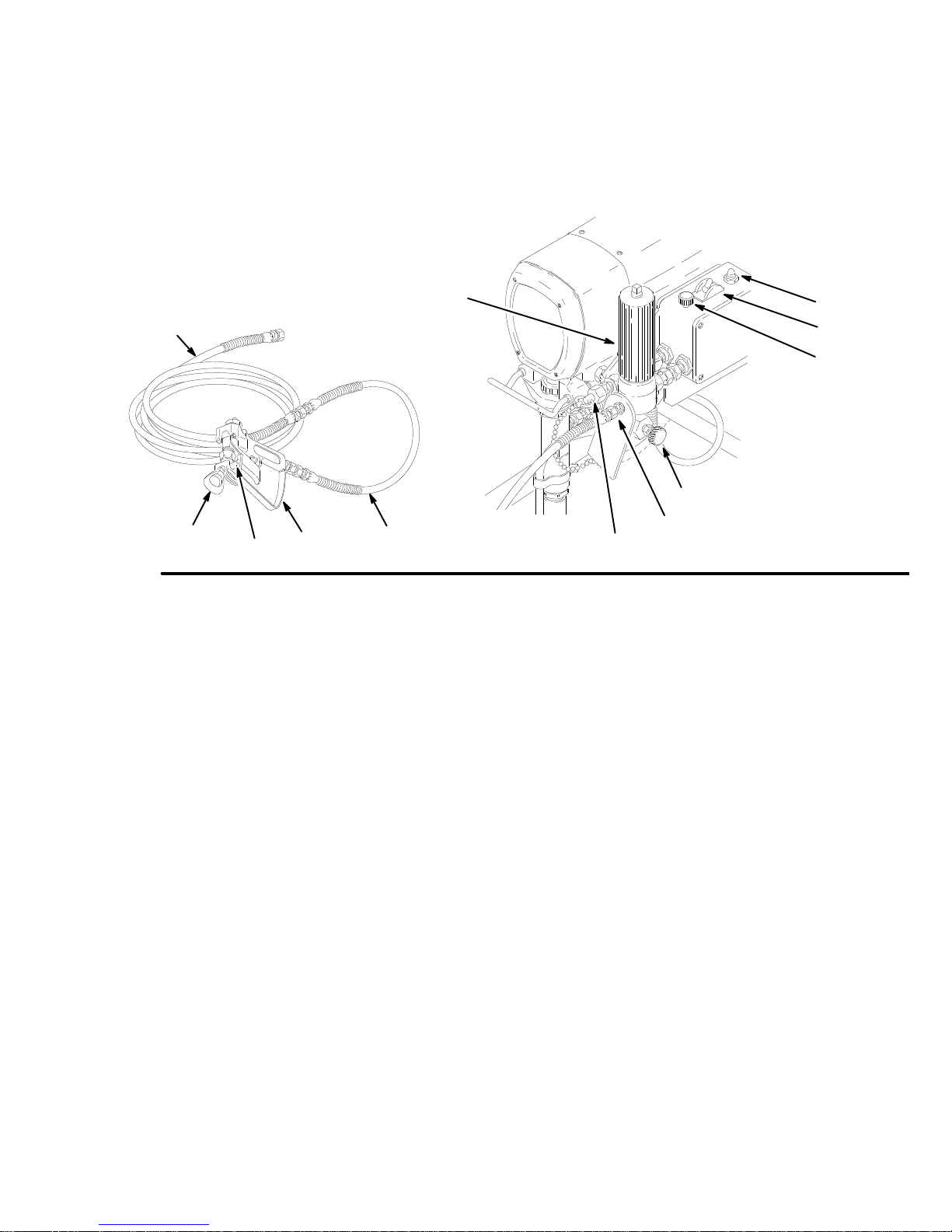
100
Fig.
1
KEY
66
61
76
67
73
A
B
C
75
40 Nipple,
61
66
66b
67
73 Motor
74
75
76
100
101
102
A
B
C
D SwitchTip
E
FT
for second hose
Pail hanger
Fluid Filter
Nipple, for the main fluid hose
Drive Assembly
Pressure drain valve
Pressure control
Displacement pump
Main fluid hose
Whip hose
Contractor gun
Reset button
On/OFF switch
Pressure Adjusting Knob
RAC IV tip guard
rigger safety shown locked
74
66b
40
E
102
D
101
Page 4
WARNINGS
High Pressure Spray Can Cause Serious Injury
Observe All W
General
This
the
your
ily
or
age.
Never
Never put hand or fingers over the spray tip. Never try to “blow
back”
Always
ing.
Always follow the Pressure Relief Procedure, below, before
cleaning or removing the spray tip or servicing any system
equipment.
Never
Be
each
Medical
If any fluid appears to penetrate your skin, get emergency
medical care at once. do not treat as a simple cut. Tell the
doctor
Note
is
important to treat the injury surgically as soon as possible.
not delay treatment to research toxicity. T
with some exotic coatings injected directly into the blood
stream. Consultation with a plastic surgeon or reconstructive
hand
Spray
Be sure all gun safety devices are operating properly before
each
cause
Safety
equipment generates very high fluid pressure. Spray from
gun, leaks or ruptured components can inject fluid through
skin and into your body
injury
, including the need
splashed into the eyes or
point the spray gun at anyone or at any part of the body
paint; this is Not an air spray system.
have the tip guard in place on the spray gun when spray
try to stop or deflect leaks with your hand or body
sure equipment safety devices are operating properly before
use.
Alert––Airless Spray W
exactly what fluid was injected.
to Physician
surgeon may be advisable
Gun Safety Devices
use. Do not remove or modify any part of the gun; this can
a malfunction and result in serious bodily injury
arnings. Read and understand all instruction manuals before operating equipment.
FLUID
and cause extremely serious bod
for amputation. Also, fluid injected
on the skin can cause serious dam
INJECTION HAZARD
.
ounds
:
Injection in the skin is a traumatic injury. It
oxicity is a concern
.
Do
.
. For Professional Use Only.
Safety Latch
Whenever you stop spraying, even for a moment, always set
the
gun trigger safety in the closed or “safe” position, making the
gun
-
-
inoperative. Failure to set the safety latch can result in acci
triggering of the gun.
dental
Diffuser
The gun diffuser breaks up spray and reduces the risk of fluid
.
injection
regularly
remove
-
gun
the gun. If the fluid emitted
stream,
when the tip is not installed. Check dif
. Follow the
the spray tip. Aim the gun into a metal pail, holding the
firmly to the pail. Using the lowest possible pressure, trigger
replace the dif
Pressure Relief Procedure
is not
fuser immediately
diffused into an irregular
.
Tip Guard
Always
have the tip guard in place on the spray
ing. The tip guard alerts you to the fluid injection hazard and
reduce, but does not prevent, the risk
helps
ing
your fingers or any part of
your body close to the spray tip.
gun while spray
of accidentally plac
Trigger Guard
Always
have the trigger guard in place on the gun when spray
ing to reduce the risk of accidentally triggering the gun if it is
dropped
Spray T
Use extreme caution when cleaning or changing spray tips. If
the
mediately
then
NEVER
fully
or bumped.
ip Safety
spray tip clogs while
. ALWAYS follow the
remove the spray tip to clean it.
wipe of
relieved and the gun trigger safety is locked.
f build-up around the spray tip until pressure is
spraying, lock the gun trigger safety im
Pressure Relief Procedure
fuser operation
, below
, then
and
-
-
-
-
-
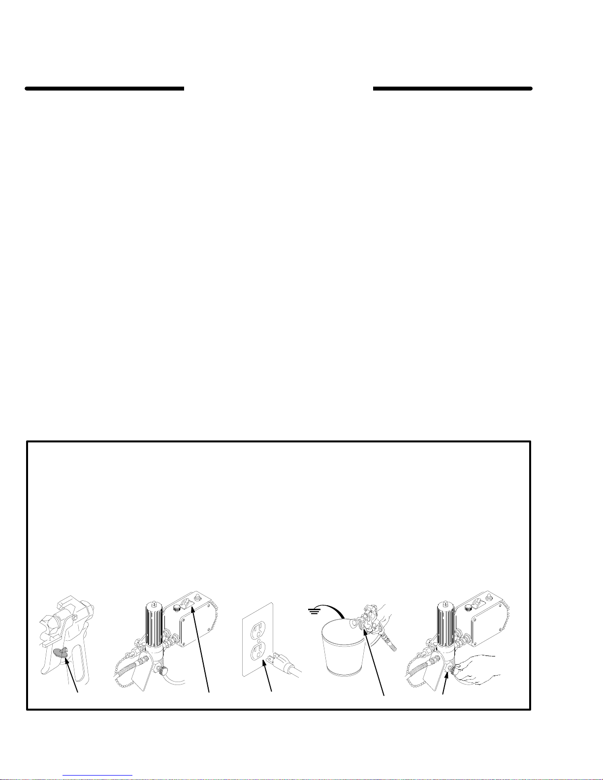
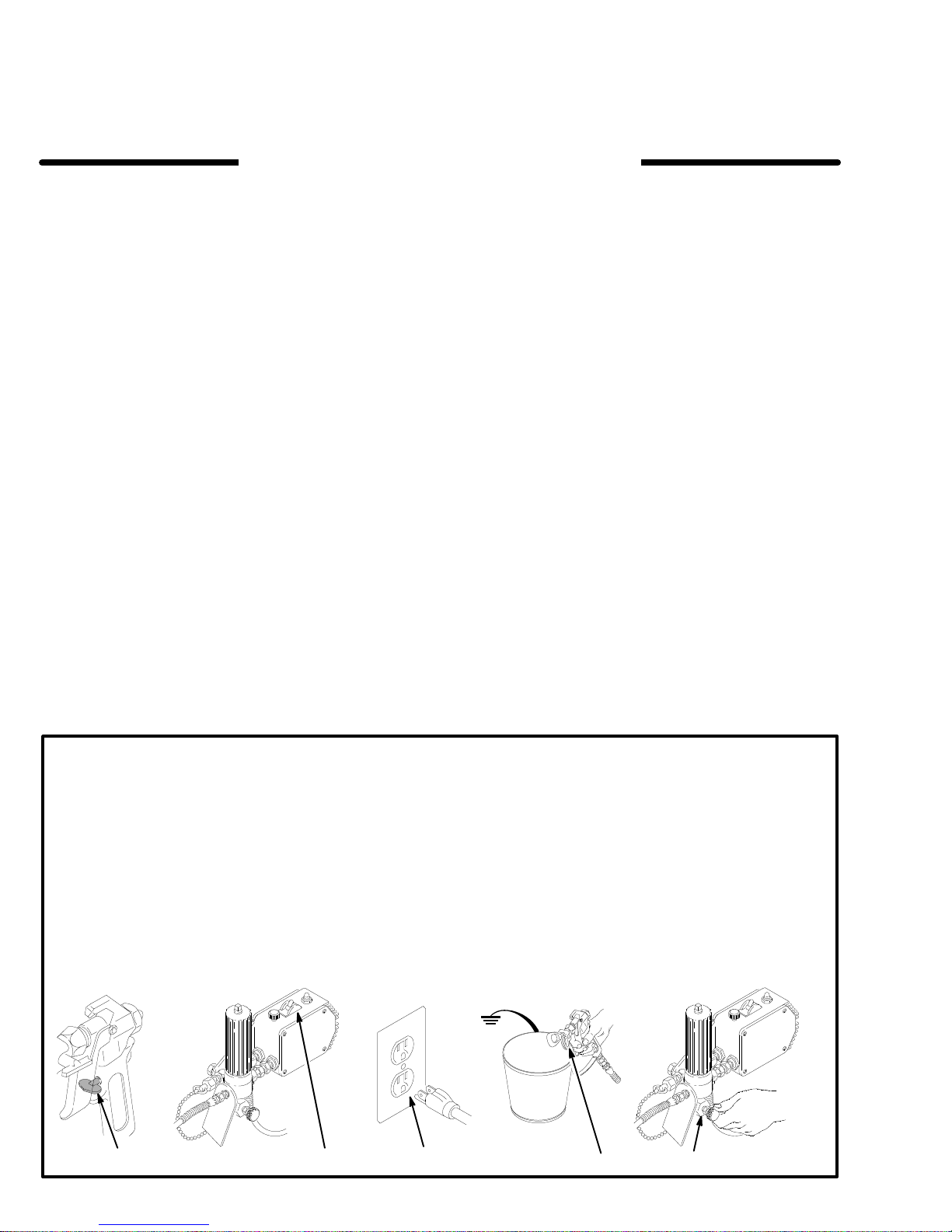
Pressure
To
reduce the risk of serious bodily injury
jection,
or injury from moving parts or electric shock, always
this procedure whenever you shut off the sprayer, when
checking
stalling,
stop
1.
2.
3.
Relief Procedure
splashing fluid or solvent in the eyes or on the skin,
or servicing any part of the spray system, when in
cleaning or changing
spraying.
Lock the gun trigger safety
Turn the ON/OFF switch to OFF.
Unplug the power supply cord.
spray tips, and whenever you
.
, including fluid in
follow
1,5 2 4
4.
Unlock the gun trigger safety. Hold a metal part of the
firmly to the side of a
-
-
gun
ger
the gun to relieve the pressure.
5.
Lock the gun trigger safety
6. Open the pressure drain valve, having a container
If you suspect that the spray tip or hose is completely
clogged,
lowing the steps above,
retaining
ally,
to catch the drainage. Leave the valve open until
ready
you
are ready to spray again.
or that pressure
nut or hose coupling
then loosen completely
3
grounded metal pail, and trig
.
has not been fully relieved after fol
very slowly loosen the tip guard
to relieve the pressure gradu
. Now clear the tip or hose.
6
-
-
-
01216A
4
307-785
Page 5

EQUIPMENT MISUSE HAZARD
General
Any misuse of the spray equipment or accessories, such as
overpressurizing, modifying parts, using incompatible chemicals and fluids, or using worn or damaged parts, can cause
them
or
property
Never
cause
Check
or
Always
tor
Safety
to rupture and result in fluid injection, splashing in the eyes
on the skin, or other serious bodily injury
damage.
alter or modify any part of this equipment; doing so
it to malfunction.
all spray equipment regularly and repair or replace worn
damaged parts immediately
wear protective eyewear
as recommended by the fluid and solvent manufacturer
.
, gloves, clothing and respira
, or fire, explosion or
could
.
HOSE SAFETY
High
pressure fluid in the hoses can
hose develops a leak, split or rupture due to any kind of wear,
damage
cause a skin injection injury or other serious bodily injury or
property
All
spring guards help protect the hose from kinks or bends at or
close
Tighten all fluid connections securely before each use. High
pressure
sure
Never
hose for cuts, leaks, abrasion, bulging cover, or damage or
movement
ist, replace the hose immediately. Do not try to recouple high
pressure hose or mend it with tape or any other device. A repaired
or misuse, the high pressure spray emitted from it
damage.
fluid hoses must have spring guards on both ends!
to the coupling which can result in hose rupture.
fluid can dislodge a loose coupling or allow high pres
spray to be emitted from the coupling.
use
a damaged hose. before each use, check the entire
of the hose couplings. If
hose cannot contain the high pressure fluid.
be very dangerous. If the
can
The
any of these conditions ex
System
This
Pressure
used are rated to withstand this pressure. Do not exceed the
maximum working pressure of any component or accessory
used
Pressure
sprayer can develop
. Be sure that all spray equipment and accessories
in the system.
3000 psi (210 bar) Maximum Working
Fluid and Solvent Compatibility
All
chemicals used
ible
with the wetted parts shown in the Technical Data
44.
Consult your chemical supplier to ensure compatibility
Do
not use 1,1,1-trichloroethane, methylene chloride, other ha
logenated hydrocarbon solvents or fluids containing such sol-
-
vents in this equipment, which contains aluminum and/or zinc
Such
parts.
the possibility of explosion, which could cause death, serious
bodily
injury and/or substantial property damage.
Handle
and route hoses carefully
equipment.
of
the pump and gas engine. Do not use fluids or solvents which
are not compatible with
not
expose Graco hose to temperatures above 180 F (82
or
below –40 F (–40
in the sprayer must be chemically compat
use could result in a serious chemical reaction, with
. Do not pull on hoses to move
Keep hoses clear of moving parts and hot
the inner tube and cover of the hose. Do
C).
Hose Grounding Continuity
Proper
hose grounding continuity is essential to maintaining a
grounded
-
fluid
tag on it which specifies the maximum electrical resistance,
contact
sistance
-
for your hose to check the resistance. If the resistance exceeds
the recommended limits, replace it immediately. An ungrounded
ardous.
spray system. Check the electrical resistance of your
hoses at least once a week. If your hose does not have a
the hose supplier or manufacturer for the maximum re
limits. Use a resistance meter in the appropriate range
or poorly grounded hose can make
Also read
FIRE OR EXPLOSION HAZARD.
your system haz
on page
-
.
-
surfaces
C)
-
-
FIRE OR EXPLOSION HAZARD
Static
electricity is created by the flow of fluid through the pump
and hose. If every part of the spray equipment is not properly
grounded, sparking may occur, and the system may become
hazardous. Sparking may also occur when plugging in or unplugging a power supply cord or using a gasoline engine.
Sparks can ignite fumes from solvents and the fluid being
sprayed, dust particles and other flammable substances,
whether you are spraying indoors or outdoors, and can cause
a fire or explosion and serious bodily injury and property
damage.
If you experience any static sparking or even a slight shock
while using this equipment, stop spraying immediately.
Check the entire system for proper grounding. Do not use the
system again until the problem has been identified and
corrected.
Grounding
To
reduce the risk of static sparking, ground the sprayer and
other
spray equipment used or located
your
local electrical code for detailed grounding instructions for
your area and type of equipment. Be sure to ground all of this
equipment:
spray
1.
2.
3.
Sprayer:
true
Fluid
500
ing
Spray
erly
connect a ground wire and clamp
earth ground.
hoses:
ft (150 meter) combined hose length to ensure ground
continuity
grounded fluid hose and sprayer
use only grounded hoses with
. See
Hose Grounding Continuity.
gun:
obtain grounding through connection
in the spray area. Check
(supplied) to a
a maximum of
.
all
to a prop
5.
Fluid supply container:
6.
All solvent pails used when flushing,
code. Use only metal pails, which are conductive. Do not
the pail on a non–conductive surface,
place
or
cardboard, which interrupts the grounding continuity
7.
To
maintain grounding
pressure
side
Flushing
Reduce the risk of skin injection injury, static sparking, or
splashing
of
this manual. Follow the
4, and remove the spray tip before flushing. Hold a metal part
of
the gun firmly to the side of
lowest
,
always hold a metal part of the gun firmly to the
of a grounded metal pail, then trigger the gun.
Safety
by following the flushing procedure given on page 15
possible fluid pressure during flushing.
according to local code.
according to local
continuity when flushing or relieving
Pressure Relief Procedure
a grounded metal pail and use the
MOVING PARTS HAZARD
Moving
parts
parts.
the
sprayer
before checking
it
from starting accidentally
can pinch or amputate your fingers or other body
KEEP CLEAR of moving parts when starting or
. Follow the
Pressure Relief Procedure
or servicing any part of the sprayer
.
IMPORTANT
United States Government safety standards have been
-
adopted
standards
the
under the Occupational Safety and Health Act. These
– particularly the General Standards,
Construction Standards, Part
1926 – should be consulted.
such as paper
, to prevent
Part 1910, and
.
on page
operating
on page
4
4.
Object being sprayed:
according to local code.
Page 6

Avertissement
La
pulvérisation à haute pression peut causer des blessures très graves.
Réservé exclusivement à l’usage professionnel. Observer toutes les consignes de sécurité.
Bien lire et bien comprendre tous les manuels d’instructions avant d’utiliser le matériel.
RISQUES D’INJECTION
Consignes
Cet
appareil produit un fluide à très haute pression. Le fluide pulvérisé
par
le pistolet ou le fluide sous pression provenant de fuites ou de
ruptures peut pénétrer sous la peau ou à l’interieur du corps et
entrainer des blessures très graves, voir même une amputation.
Même
les
yeux peut aussi entrainer des blessures graves.
Ne
jamais pointer le pistolet vers quelqu’un ou vers une partie quel
conque
du
pulvérisateur
pareil
Toujours
dant
Toujours
donnée
sateur,
pareil.
Ne
jamais
le corps.
Avant
fonctionnent
Soins
En
cas de pénétration de fluide sous la peau:
ment
comme
Avis
traumatisme. Il est important de traiter chirurgicalement
cette blessure immédiatement. Ne pas retarder le traitement pour effectuer des recherches sur la toxicité. Certains
revêtements exotiques sont dangereusement toxiques
quand ils sont injectés directement dans le sang. Il est
souhaitable de consulter un chirurgien esthétique ou un
chirurgien
generales de sécurité
sans être sous pression, le fluide éclaboussant ou entrant dans
du corps. Ne jamais mettre la main ou les doigts sur l’ajutage
n’est pas un compresseur pneumatique.
la pulvérisation.
plus loin, avant de nettoyer ou d’enlever l’ajutage du pulvéri
ou d’ef
chaque utilisation, bien s’assurer
. Ne jamais essayer de “refouler” la peinture. Cet ap
garder la
observer la
protection de l’ajutage en place sur le pistolet pen
March à
fectuer un travail quelconque sur une
essayer d’arrêter ou de dévier les fuites avec la main ou
correctement.
Suivre pour Détendre la Pression
partie de l’ap
que les dispositifs de sécurité
medicaux
des soins medicaux d’urgence.
une simple coupure.
au medecin
: La pénétration des fluides sous la peau est
demander immediate
Ne pas soigner cette blessure
un
spécialisé dans la reconstruction des mains.
Dispositifs de sécurité du pistolet
Avant chaque utilisation, bien s’assure que tous les dispositifs de
sécurité du pistolet fonctionnent correctement. Ne pas enlever ni
modifier
une partie quelconque du pistolet; ceci risquerait
un
mauvais fonctionnement et des blessures graves.
Verrou
de sécurité
A
-
-
chaque fois que l’on s’arrête de pulvérisér
court
instant, toujours mettre le verrou de
position
“fermée” ou “sécurité” (“safe”) pour empêcher le pistolet
fonctionner
déclencher
. Si le verrou de sécurité
accidentellement. Voir la figure, ci–dessus.
n’est pas mis, le pistolet peut se
, même s’il s’agit d’un
sécurité du pistolet sur la
Diffuser
Le
dif
-
-
-
-
fuseur du pistolet sert à diviser le jet et à réduire les risques d’in
jection accidentelle quand l’ajutage n’est pas en place. Vérifier le
fonctionnement
détendre
la
Pression
Pointer
le pistolet dans un seau en métal, en le maintenant fermement
contre
le seau. Puis, en utilisant la pression la
appuyer
sous
forme de jet
Protection
Toujours
du
pulvérisateur
attire
l’attention sur les risques d’injection et contribue à réduire, mais
n’évite
pas le risque, que les doigts ou une partie quelconque du corps
ne
passent
pulvérisateur.
Consignes
du dif
la pression en observant la
donnée plus loin puis enlever
sur
la gachette du pistolet. Si le fluide projete
fuseur régulièrement.
irrégulier
, remplacer immédiatement le dif
Marche à
Pour cette vérification,
Suivre pour Détendre
l’ajutage du pulvérisateur
plus faible possible,
de l’ajutage
maintenir la protection de l’ajutage en place sur le pistolet
pendant la pulvérisation. La protection de l’ajutage
accidentellement à proximité immédiate de l’ajutage du
de sécurité concernant l’ajutage du
pulvérisateur
Faire extremement attention à l’occasion du nettoyage ou du
remplacement
pendant
du pistolet. ToujourS bien observer la Marche à Suivre pour
Détendre
le
nettoyer
Ne jamais essuyer ce qui s’est accumulé autour de l’ajutage du
pulvérisateur
que
le verrou de sécurité du pistolet ne soit engagé.
des ajutages du pulvérisateur
la pulvérisation, mettre
la
Pression
.
avant que la pression ne soit completement tombée et
puis enlever l’ajutage du pulvérisateur pour
immédiatement le verrou de sécurité
. Si l’ajutage se bouche
d’entraîner
n’est pas
de
dif
fusé
fuseur.
-
.
Marche
à Suivre pour Détendre la Pression
Pour réduire les risques de blessures graves, y compris les
blessures
boussures
ment
à
suivre à chaque fois que l’on
sion
ou
1. Engager
2. Basculer
3. Debrancher
par injection de fluide ou celles causées par des écla
dans les yeux ou sur la peau, des pièces en mouve
ou par électrocution, toujours bien observer cette marche
arrête le pulvérisateur
de la vérification,
du reglage ou du nettoyage du systeme
lors du changement des ajutages.
le verrou de sécurité du pistolet.
(OFF).
l’interrupteur de commande de pression sur ARRET
le cordón d’alimentation.
1,5
6
307-785
, à l’occa
4. Désengager
-
-
5.
-
6. Ouvrir
Si
tenant
contre
libérer
Engager le verrou de sécurité du pistolet.
que l’on soit pret à se servir de nouveau du pulvérisateur.
Débrancher
l’on soupçonne que le tuyau ou l’ajutage du est complète
le verrou de sécurité du pistolet. Tout en main
une partie métallique du pistolet fermement appuyée
le côté d’un seau en métal, actionner le pistolet pour
la pression.
la soupape de sécurité et la laisser ouverte jusqu’a ce
le fil de la bougie.
ment bouche, ou que la pression n’a pas été complètement
après avoir procede aux operations ci–dessus,
libérée
très lentement un raccord du bout du tuyau
rer
retenue
de
la
pression.
24
3
la protection de l’ajutage et libérer progressivement
6
desser
ou l’écrou de
01216A
-
-
-
Page 7

RISQUES EN CAS DE MAUVAISE UTILISATION DU MATERIAL
Consignes
Toute
soires
les
modifications de pièces, l’utilisation de produits chimiques et de
matières
peut
traîner
incendie,
Ne
jamais alterer ou modifier une piece de cet appareil; ceci risquerait
d’entraîner
Vérifier
ments et réparer ou remplacer immédiatement les
pièces
Le
fluide à haute pression circulant dans les tuyaux peut être très dan
gereux.
à
la suite de l’usure, de dégâts ou d’une mauvaise utilisation, les pro
jections
des
blessures graves par pénétration sous la peau ou par contact,
ainsi
Tous
protection
la
formation de pliures, de boucles ou de nœuds sur les tuyaux qui
pourraient
son
voisinagé.
Serrer
sous
jet
à haute pression s’échappant par le raccord.
Ne
jamais utiliser un tuyau endommagé. Ne pas essayer de refaire
le raccord d’un tuyau haute pression ni de réparer
ruban
résister
générales de sécurité
utilisation anormale de l’appareil de pulvérisation
comme, par exemple, la mise sous une pression excessive,
incompatibles et l’utilisation
causer des dégâts à l’appareil ou des ruptures de pièces et
une injection de liquide
une explosión ou d’autrès dégâts.
son mauvais fonctionnement.
régulièrement
usées ou abîmées.
MESURES
En cas de fuite sur
de fluide haute pression qui en
que des dégâts matériels.
les tuyaux flexibles doivent avoir des ressorts spirale de
aux bouts!
entraîner la
fermement tous les raccords avant chaque utilisation. Le fluide
pression peut faire sauter un raccord desserre ou produire un
adhesif ou par tout autre moyen. Un tuyau réparé ne peut pas
au fluide sous pression.
tout l’appareil de pulvérisation et ses equipe
DE
le tuyau, de fissure, déchirure ou rupture
Les spirales de protection
rupture du tuyau à l’endroit du raccord ou à
de pièces usées ou abîmées
ou d’autrès blessures sérieuses, un
SECURITE CONCERNANT LES TUY
proviennent peuvent entraîner
ou des acces
en
contribuent à eviter
le
tuyau avec du
-
-
-
-
-
RISQUES D’INCENDIE OU D’EXPLOSION
De
l’électricité statique est produite par le
vitesse
dans la pompe et dans
l’appareil
masse
risque d’être dangereux. Des étincelles peuvent également se pro
duire
d’alimentation. Les étincelles sont suffisantes pour allumer les
vapeurs
sieère ainsi que d’autrès substances inflammables, quand on
pulvérisé
cendie
matériels. Toujours brancher le pulvérisateur
vant
la
tions
y
prennent feu.
S’il
tez la moindre décharge, arrêtez immédiatement la pulvérisation.
Vérifiez
pas
Mise
Pour réduire les risques de production d’étincelles d’électricité
statique,
vant
à
dans
ou
équipements
1.
de pulvérisation ne sont pas convenablement reliées à la
ou à
la terre, des étincelles peuvent se produire et l’appareil
à l’occasion
de solvants et le fluide pulvérisé, les fines particules de pous
à l’intérieur ou à l’extérieur
ou une explosión, ainsi que des blessures graves et des
à au moins 6 m (20 pieds) de l’appareil et de l’endroit où se fait
pulvérisation. Ne pas brancher ou débrancher un cordón d’alimena
quel qui’il soit dans
à le moindre risque
se
produit des étincelles d’électricité statique, ou si vous ressen
que le système entier est
du système avant que le problème soit identifié et corrigé.
du branchement ou du débranchement du cordón
que des vapeurs encore présentes dans l’air
à la terre ou à la masse
le pulvérisateur et tous les équipements utilisés ou se trou
dans la zone de pulvérisation doivent être reliés à la terre ou
la masse. Pour connaître le detail des instructions de mise à la terre
la region et le type particulier d’équipement, Consulter le code
les réglementations électriques locales. S’assurer
Pulvérisateur:
qui
une
utiliser
être
de pulvérisation suivants sont bien reliés à la terre:
Brancher le cordón d’alimentation ou la rallonge
doivent être équipés
prise de courant
d’adaptateur
prevues pour 15 ampères.
les tuyaux. Si toutes les pièces de
la zone où se fait la pulvérisation quand il
d’une prise à 3 fiches en bon état, dans
convenablement mise à la terre. Ne pas
. T
outes
passage du fluide à grande
-
-
, et elles peuvent causer un in
dans une prise se trou
bien mis à laterre. Ne vous servez
que tous les
les rallonges doivent avoir 3 fils et
-
dégâts
-
-
-
-
Pression
Ce
pulvérisateur peut produire une
bar
(3000 lb/po2). S’assurer que tous les éléments du pulvérisateur
et
ses accessoires sont conçus pour résister à
de
travail de ce pulvérisateur
de
travail
pareil.
Compatibilité
Bien
ment
nical
et brochures du fabricant des fluides et solvants utilisés avant de s’en
servir
d’aucun des éléments ou accessoires utilisés avec cet ap
chimique des corps
s’assurer que tous les corps des solvants utilisés sont chimique
compatibles avec les parties mouillées indiquées dans les
Data
, à la page 44. T
dans ce pulvérisateur
oujours lire
Pression Maximum De T
la pression maximum
. Ne pas depasser la pression maximum
soigneusement les documents
.
ravail
Tech-
210
-
-
AUX FLEXIBLES
Manipuler
chemin.
de
intérieure
températures
(–40 F).
Continuité
Une
pour
fiez la résistance électrique de vos tuyaux à fluides et à air
une fois par semaine. Si votre tuyau ne comporte pas d’étiquette qui
précise
fournisseur
tance
priée
les
tuyau
entraîner
D’INCENDIE OU D’EXPLOSIÓN ci–dessus.
2.
3.
4.
5.
6.
7.
Mesures
Pour
les
sures,
15
sion”
le
rincage
puyée
faible
les tuyaux avec precaution et choisir soigneusement leur
Ne pas déplacer le fluide en tirant sur le tuyau.
fluides ou de solvants qui ne sont pas compatibles avec l’enveloppe
ou extérieure du tuyau. NE P
supérieures à 82C (180F) ou inférieures à –40
AS exposer le tuyau à des
Ne pas utiliser
C
de la mise à la terre des tuyaux
bonne
continuité de la mise à la terre des tuyaux est essentielle
maintenir la mise à la terre de l’ensemble de vaporisation. Véri
la résistance électrique
de tuyaux ou la fabricant pour avoir les límites de résis
maximum. Utilisez un mètre de
pour votre tuyau et vérifiez la résistance. Si celle–ci dépasse
límites recommandées, remplacez le tuyau immédiatement. Un
sans mise à la terre ou avec une mise à la terre incorrecte peut
des risques pour votre systeme. Lisez
Tuyaux flexibles:
n’utiliser que des tuyaux comportant une mise
terre,
et ayant une longueur maximum combinée de 150 m (1500
Se reporter également au paragraphe
pieds).
mise
à la terre des tuyaux.
Pistolet
:
flexible
terre.
Réaliser la mise à la terre en le raccordant à un tuyau
et à un pulvérisateur dèjá convenablement reliés à
Récipient
locales.
tions
Afin d’assurer la continuité de la mise à la
d’alimentation:
maximum, prenez contact avec le
résistance de la gamme appro
aussi
observer le code ou les réglementa
, au moins
LES RISQUES
à la terre
Continuité de la
Objets, matériel ou surfaces reçevant la pulvérisation:
server
le code ou les réglementations locales.
Tous
les seaux de solvants
code ou les réglementations locales. N’utiliser que des saux
métalliques
sur
une surface non conductrice comme sur du papier ou du
carton
Pour
le
matériel ou quand on libére la pression
une
côté
conducteurs de l’électricité. Ne pas mettre le seau
car cela interromprait la continuité de la mise à la terre.
conserver la continuité
partie métallique du pistolet fermement appuyée contre le
d’un seau en métal puis appuyer sur la détente du pistolet.
utilisés pour le rinçage: observer le
de la mise à la terre quand on rince
, toujours
maintenir
-
-
-
la
-
ob-
de sécurité concernant le Rincage
réduire les risques de blessures par pénétration de la peau et
risques dûs aux etincelles d’electricite statique ou aux éclabous
observer la marche
de ce manuel. Observer la “Marche à Suivre pour
donnée à la page 6 en
. Maintenir une partie
contre le côté d’un seau en métal et utiliser la pression la plus
possible pendant le rincage.
à suivre pour le rincage donnée à la page
Détendre la Pres
enlever l’ajutage du pulvérisateur avant
métallique du pistolet fermement ap
-
-
-
Page 8
ADVERTENCIA
EL
ROCIADO a ALTA PRESIÓN PUEDE CAUSAR GRA
SOLO P
Lea y entienda todo el manual de instrucciónes antes de manejar el equipo.
Seguridad
Este
equipo genera un fluido a una presión muy alta. El rociado
de la pistola, los escapes de fluido o roturas de los componentes
lesiones extremadamente graves, incluyendo a veces la
necesidad de amputación. También, el fluido inyectado o salpicado
Nunca apuntar la pistola hacia alguien o alguna parte del
cuerpo. Nunca colocar la mano o los dedos encima de la
boquilla.
un
sistema de rociado de aire.
Siempre tener colocado el protector de la boquilla en la pistolamientras
Siempre
másabjo,
cualiquier
Nunca tratar de parar o desviar los escapes con la mano o el
cuerpo.
Asegurar
funciónando
Tratamiento
Si pareciera que un poco de fluido penetró la piel, conseguir
Tratamiento
herida como un simple corte. Decir al médico exactamente
fluido fue.
cua
A
viso al médico:
causa
mente la lesión a la brevedad posible. No demorar el
tratamiento
suma importancia en algunas pinturas exóticas cuando se inyectan directamente al torrente sanguineo. Sirá conveniente
consultar
de
las manos.
general
pueden inyectar fluido en la piel y el cuerpo y causar
en los ojos puede causar graves daños.
Nunca tratar de
se está pulverizando.
seguir el procedimiento de descarga de presión,
antes de limpiar o sacar la boquilla o de dar servicioa
equipo del sistema.
que todos los aparatos de seguridad del equipo están
bien antes de cada uso.
médico
médico de urgencia de inmediato. no tratar la
Si se llega a inyectar este fluido en la piel se
una lesión traumática.
para investigar la toxicidad. La toxicidad es algo de
a un especialista en cirugia plástica o reconstructiva
ARA USO PROFESIONAL. RESPETE LOS A
PELIGRO DE INYECCION DE FLUIDO
“hacer retornar la pintura”; este NO es
dado
Es importante tratar
quirúrgica
VES LESIONES.
VISOS DE ADVERTENCIA.
Aparatos
Asegurar
funciónando bien antes de cada uso. No sacar ni modificar
ningúna
miento
Pestillo
Cada
momento, siempre colocar el pestillo de seguridad en la posición “cerrada” lo que deja la pistola inoperante. El no hacerlo
puede
Difusor
El
difusor de la pistola dispersa el chorro pulverizado y reduce
el riesgo de inyección cuando no está instalada la boquilla.
Revisar
procedimiento de descarga de presión, dado más abajo, y
después
co,
sosteniéndola bien firme contra el. Utilizando la presión más
bajo
perso
Protector
Siempre
mientras
contra
la
colocación accidental de los dedos o cualquier otra parte del
cuerpo
Seguridad
Tener
ra a obstruirse mientras está pulverizando,
-
tillo de la pistola de inmediato. Siempre seguir el procedimiento de descarga de presión y después sacar la boquilla
para
Nunca limpiar la acumulación de pintura alrededor de la
boquilla antes de que se haya descargado por completo la
presión
de seguridad de la pistola pulverizadora
que todos los aparatos protectores de la pistola están
pieza de la pistola pues podria causar el malfuncióna
de
la misma con las consiguientes lesiones personales.
de seguridad
vez que se deje de pulverizar
llevar al disparo imprevisto de la pistola.
con regularidad el
sacar la boquilla. Apuntar la pistola a un balde metáli
posible, disparar la pistola. Si el fluido emitido no sale dis
en un
chorro irregular
de la boquilla
tener el protector de la boquilla colocado en la pistola
se está pulverizando.
el peligro de inyección
cerca de la boquilla.
funciónamiento del difusor
, reemplazar de inmediato el difusor
, aunque sea por un breve
Este protector llama la atención
y ayuda a reducir
de la boquilla pulverizadora
mucho cuidado al limpiar o cambiar las
limpiarla.
y el pestillo este enganchado.
boquillas. Si llega
enganchar el pes
-
. Seguir el
-
.
, pero no evita,
-
-
Procedimiento
Para
reducir el riesgo de
cluyendo inyección o lesiones causadas por piezás en
movimiento o choque eléctrico, siempre seguir este
procedimiento
o
dar servicio a cualquier
al
instalar
deja
1.
2. Mover el interruptor eléctrico (ON/OFF) a la posición
3.
4. Desenganchar
, limpiar o cambiar las boquillas, y cada vez que se
de pulverizar
Enganchar el pestillo de la pistola.
OFF
(apagado).
Desenchufar el cordón electrico.
metálica de la pistola bien firme contra un balde de
metal,
de descarga de presión
sufrir graves lesiones corporales, in
al apagar la máquina pulverizadora, al revisar
y disparar la pistola para descargar la presión.
parte del sistema de pulverización,
.
el pestillo de la pistola.
Sujetar una parte
1,5 2 4
8
307-785
5.
Enganchar el pestillo de la pistola.
-
6. Abrir
Si se sospecha que la boquilla o la manguera está completamente obstruida, o que no se ha descargado por completo
anterior, aflojar muy lentamente la tuerca de retención del
protector
guera y descargar gradualmente la presión, después,
aflojarlo por completo. Luego, despejar la boquilla o la
manguera.
3
la válvula de presión y tener listo un reclipiente para
recibir la pintura. Dejar la válvula de alivio de presión
abierta hasta que se este nuevamente listo para pulverizar.
la
presión después de haber seguido el procedimiento
de la boquilla o acoplamiento de la punta de la man
6
-
01216A
Page 9

PELIGRO POR MAL USO DEL EQUIPO
Seguridad
Cualquier
como sobre presurización, modificación de piezás, uso de
matériales
piezás dañadas o desgastadas, puede hacen que se rompan
y causen la inyección de fluido u otras lesiones corporales
graves,
Nunca alterar o modificar ningúna pieza de este equipo; el
hacerlo
Revisar con regularidad el equipo pulverizador y reparar o
reemplazar
general
mal uso del equipo pulverizador o los accesorios, tal
y productos quimicos incompatibles, o utilización
incendio, explosión o dañon a la propiedad.
podria causar una avería.
de inmediato las piezás dañadas o desgastadas.
de
SEGURIDAD EN EL USO DE LAS MANGUERAS
El fluido que escapa a alta presión por las mangueras puede
muy peligroso. Si en la manguera se desarrolla un
ser
una
rotura o rajadura debido a cualquier tipo de desgaste, daño
o maltrato, el chorro a alta presión emitido por alli puede causar
una lesion por inyección u otras lesiones corporales graves o
a la propiedad.
daños
!Todas Las Mangueras Para Fluidos Tienen Que Tener
Guardas De Resorte En Ambos Extremos! Estas protegen
las mangueras contra dobleces o retorceduras en los
acoplamientos o cerca de ellos, los que
roturas de la manguera.
Antes
de usarlas, apretar bien
fluido a alta presión puede desalojar un acoplamiento suelto o
dejar
que por el escape un chorro a alta presión.
Nunca usar una manguera que está dañada. Siempre,
revisarla
abultada, o acoplamientos sueltos o dañados. Si llegara a en
contrarse cualquiera de estás condiciónes, reemplazar de inmediato la manguera. NO intentar racoplar una manguera de
alta presión o enmendarla con cinta adhesiva u otro matérial
similar. Una manguera que ha sido remendada no aguante el
fluido
en busca de cortaduras, escapes, abrasion, cubierta
a alta presión.
firmes todas las conexiones. El
podrian traducirse en
escape,
-
PELIGRO DE INCENDIO O EXPLOSION
Presión
está
Presión
verizador y
la presión máxima de trabajo de está pulverizadora. NO exceder la presión máxima de trabajo de ningún componente o
accesorio
del sistema
pulverizadora puede desarrollar 210 barías (3000 psi)
De T
rabajo Máxima
sus accesorios tienen la capacidad para aguantar
de este sistema.
. Asegurar que todo el equipo pul
De
Compatibilidad de fluido
Siempre leer las instrucciónes del fabricante del fluido y solvente
antes de usarlos en está
44.
na
Siempre usar gafas, guantes, vestimetas protectora y un
respiradero,
del solvente.
Manejar y pasar cuidadosamente las mangueras. No tirar de
las mangueras para mover el equipo. No usar fluidos o solventes
dela manguera. No exponer las mangueras a temperaturas
sobre
Continuidad
tal como recomiendan los fabricantes del fluido
que sean incompatibles con el tubo interno y la cubierta
82C (180F) o bajo –40C (–40
del circuito de puestá a tierra de la
pulverizadora, dadas en la pági
F).
manguera
La continuidad del circuito de puestá a tierra apropiado es
esencial para mantener conectado a tierra el sistema pulverizador. Es indispensable revisar la resistencia eléctrica
máxima
vez
se
el provédor o fabricante de la manguera para la información
sobre
la
límites
riesgado
a tierra en malas condiciónes. Leer también la información
sobre RIESGO DE INCENDIO O EXPLOSION
de las mangueras de aire y de fluido por lo menos una
a la semana. Si la manguera no tiene una etiqueta
especifica la resistencia eléctrica, ponerse en contacto con
los límites de resistencia. Usar un metro de resistencia en
gama apropiade para comprobar la resistencia; si excede los
recomendados, reemplazarla
tener una manguera sin puestá a tierra o con la puestá
de inmediato. Es muy ar
en la cual
, más arriba.
-
-
y
-
El
flujo a alta velocidad del fluido al pasar por la bomba y man
crea electricidad estática. Si todas las partes del
guera
pulverizador no tienen buena tierra, pueden ocurrir chispas,
convirtiendo al sistema en algo peligroso. También, pueden
producirse chispas a enchufar o desenchufar el cordón
electrico
inflamar
verizado, particulas de polvo y otras sustancias in flamables,
sea
o
Enchufar siempre la pulverizadora a un tomacorriente que se
encuentre
que se va a rociar. No enchufar o desenchufar ningún cordón
electrico
ista
Si
choque
de inmediato. Revisar todo el sistema en busca de una tierra
apropiada. No usar de nuevo el sistema hasta haber identificado
Peusta
Para
pulverisadora
se
electrico
iones
de
1.
o al usar un motor
los vapores de los solventes y el chorro de fluido pul
al aire libre o bajo techo, lo que podria causar una explosión
incendio y graves lesiones corporales
a por lo menos 6 m (20
en el lugar
la posibilidad de que queden
ocurre una chispa de electricidad estática o incluso un ligero
electrico mientras se usa el equipo, dejar de pulverizar
y soluciónado el problema.
donde se está rociando cuando todavia ex
de gasolina. estás chispas pueden
pies) de la maquina y del area
vapores inflamables en el aire.
a tierra
reducir el reisgo de chispas estáticas, conectar a tierra la
encuentre en el
a tierra exigidas para la zona
conectar a tierra todo este equipo pulverisador:
Pulverizadora:
sor, cada uno un enchuf de très patas en buen estádo, a
un
adaptador. Totos los cables extensores tienen que tener
très
y todo el otro equipo de pulverisar que se use o
lugar que se va a rociar
de la localidad para las instrucciónes
enchufar el cordón electrico, o cable
tomacorreinte con puesat a tierra aporpiado. No usar un
hilos y una capacidad de 15 amperios.
equipo
y daños al a propiedad.
. Consultar el codigo
sobre las conex
y tipo de equipo. Asegurar
exten
-
2.
Mangueras para fluidos:
a
puestá
pies),
también al párrafo sobre continuidad del circuito de
puestá
3.
-
-
Pistola:
guera
4.
Suministrar un recipiente:
localidad.
5.
Objeto
local.
6.
Todos
conformidad con el código local. Usar
de
superficie no conductiva, como papel o cartón, que interumpe
7.
Para mantenar la continuidad a tierra durante el lavado o
tierra de una longitud combinada de 150 m (500
para asequrar buena continuidad a tierra. Referirse
a tierra de la manugeura.
hace la puestá a tierra conectándola a una man-
de fluido y pulverizadora bien conectadas a tierra.
que se está rociando:
los baldes de solvente
metal,
que sean conductivos. no colocar el balde en una
la continuidad a tierra.
descarga de presión,
de
la pistola bien firme contra el costado del
después
Seguridad durante el lavado
-
Para
reducir el riesgo
piel, o que ocurra una descarga de electricidad estática,
siempre seguir las INSTRUCCIÓNES PARA EL LAVADO,
-
dadas
de
presión
lavar.
el costado de un
posible
apretar el gatillo.
en la página 15. Seguir el
en la págna 8, y quita la
Apoyar una parte metalica de
balde de metal
de fluido durante el lavado.
usar solamente mangueras con
de acuerdo al código de la
de conformidad con el codigo
usados durante el lavado, de
solamente baldes
siempre apoyar una parte metálica
de que se inyecte o salpique fluido en la
procedimiento de descarga
boquilla rociadora antes
la pistola bien firme contra
y usar le presión más baja
307-785
balde de metal,
de
9
Page 10

Setup
WARNING
Follow
these precautions to reduce the risk of a
serious injury from static sparking, fluid injection, or
rupturing the hose or the gun
All hoses must be electrically conductive.
The gun must have a tip guard.
Each part must be rated for at least 3000 psi
(210 bar) Maximum W
orking Pressure.
CAUTION
T
o avoid damaging the pressure control, which may
result in poor equipment performance and compo
nent damage, follow these precautions:
Always use grounded, flexible spray hose at
least 50 feet (25 meter) long.
Never use a wire braid hose as it is too rigid to
act as a pulsation dampener
Never install any shutof
filter (66) and the main hose (100). See Fig. 2.
Always use the main filter–outlet for one gun
operation
. Never plug this outlet.
.
f device between the
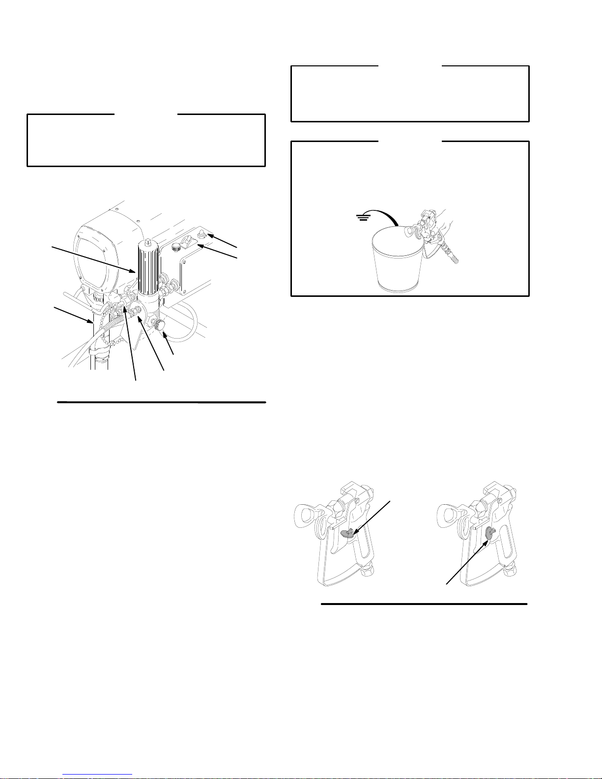
NOTE:
1.
2.
3.
-
4.
Refer to Fig. 2 while following this procedure.
Fill the packing nut until it is 1/3 full with Graco
Throat Seal Liquid (TSL).
Connect the gun, the 3 foot (0.9 meter) hose and
the 50 foot (25.2 meter) hose. Screw the assembly
onto the outlet nipple. Don’t use thread sealant
and don’t install the spray tip yet!
Follow this step to connect a second hose and
gun. Unscrew the cap (72) from the optional outlet.
Use a hose and a gun which are equivalent to the
hoses supplied with the sprayer
hoses and the gun, and then connect the hose to
the optional outlet.
Check the electrical service.
a.
The electrical requirements are 120 volt, 60 Hz
AC, 15 Amp (minimum).
b.
Use a grounded electrical outlet which is
located at least 20 feet (6 meter) from the
spray area.
. Assemble the
WARNING
Proper electrical grounding is essential to reduce
the risk of a fire or a explosion. A fire or explosion
can cause a serious injury and property damage.
Read the warning section,
HAZARD,
instructions.
on page 5 for more detailed grounding
FIRE OR EXPLOSION
c.
Do not remove the grounding prong of the
power cord and do not use an adapter
d.
The specificiations for the extension cord are
15 amps, 3 wires, grounding–type. Long
extension cords af
mance.
fect the sprayer perfor
.
-
10
307-785
Page 11
5.
Plug in the sprayer. Turn of
the power cord into a grounded electrical outlet.
6.
Flush the pump to remove the oil which was left in
the pump to protect it during shipment. Follow the
flushing procedure on page 15.
f the switch (B). Plug
Setup
7.
Prepare the paint according to the manufacturer
recommendations. Remove the skin which may
have formed on top of the paint. Stir the paint thor
oughly
. Strain the paint through a fine, nylon, mesh
bag to remove particles that could clog the filter or
the spray tip.
’s
-
Fig. 2
100
66
74
E
102
D
101
72
66b
B
C
75
01217A
307-785
11
Page 12
Operation
Use this procedure each time you start the sprayer to
help ensure that the sprayer is ready to operate and
that you start it safely
.
WARNING
T
o reduce the risk of a serious injury
Pressure Relief Procedure
you are instructed to relieve the pressure.
66
99
Fig. 3
NOTE:
See page 15.
NOTE:
Flush the sprayer if this is a first-time startup.
See Fig. 3 except where noted.
on page 4 whenever
72
, follow the
B
C
74
66b
01217A
CAUTION
Do not operate the pump without fluid in it for more
than 30 seconds, to avoid damage to the pump
packings.
WARNING
T
o reduce the risk of static sparking and splashing
when flushing, always remove the spray tip from
the gun and hold a metal part of the gun firmly to
the side of a grounded metal pail.
5.
Prime the pump.
a.
Open the pressure drain valve. T
sprayer
knob clockwise until the sprayer starts. When
the fluid comes from the drain hose, close the
valve.
b.
Unlock the gun trigger safety
in Fig. 4. Follow the warning, above, and trig
ger the gun until all air is forced out of the
system and the fluid flows freely from the gun.
c.
Release the trigger
safety
. Slowly turn the pressure–adjusting
. Lock the gun trigger
. See reference B in Fig. 4.
urn on the
. See reference A
0143
-
1.
Plug in the sprayer
Close the pressure drain valve (74). If you did not
2.
install a second hose, be sure the nipple (40) is
tightly plugged with the cap (72).
3.
Put the suction tube into the paint container
4. T
urn the pressure–adjusting knob (C) fully counter
clockwise to the minimum pressure.
12
307-785
.
B
.
-
Fig. 4
A
0137
Page 13
6.
Check all fluid connections for leaks. Relieve the
fluid pressure before tightening connections.
7.
Install the spray tip and tip guard. Lock the gun
trigger safety
instructions supplied with it.
8.
Adjust the spray pattern.
a.
Increase the pressure just until the spray from
the gun is completely atomized. Use the low
est pressure needed to get the desired results.
This procedure reduces over–spray and fog
ging, decreases the spray tip wear
extends the life of the sprayer
. Install the spray tip according to the
, and
.
Maintenance
Cleaning a Clogged Tip
WARNING
To
reduce the risk of a serious injury
Pressure Relief Procedure
you are instructed to relieve the pressure.
on page 4 whenever
WARNING
T
o reduce the risk of a serious injury from acciden
tally injecting fluid into the skin, follow these pre
cautions.
Never operate the spray gun with the tip guard
removed.
Do not hold your hand, body
the spray tip when cleaning or checking a
clogged tip. Always point the gun toward the
ground or into a pail when checking to see if the
tip is clear
.
, follow the
, or a rag in front of
Operation
If more coverage is needed, use a larger tip
b.
rather than increasing the pressure.
c. T
lock the gun trigger safety
nut. Position the tip guard horizontally for a
horizontal pattern or vertically for a vertical
pattern. T
-
-
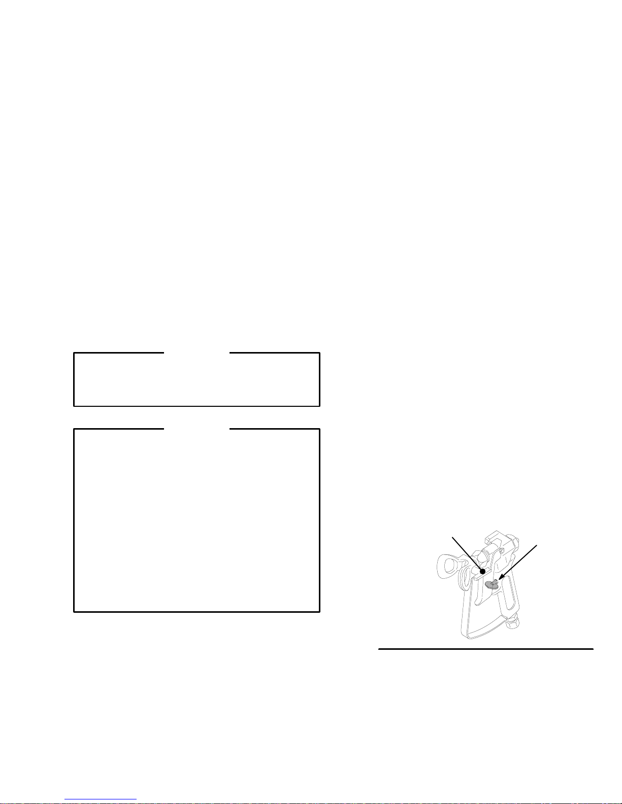
2.
If the spray tip clogs, release the gun trigger
the gun trigger safety, and rotate the handle (A) of
the RAC IV by 180. See Fig. 5, which shows the
handle in the spraying position and the gun trigger
safety (B) in the locked position.
3.
Unlock the gun trigger safety
a waste container
again.
-
-
4.
Return the handle to the original position, unlock
the gun trigger safety, and resume spraying.
5.
If the tip is still clogged, lock the gun trigger safety
shut of
pressure drain valve. Clean the spray tip as shown
in manual 307–848.
est the spray pattern. T
ighten the retaining nut.
. Lock the gun trigger safety
f and unplug the sprayer
A
o adjust the pattern,
, loosen the retaining
, lock
. T
rigger the gun into
, and open the
B
,
Do not try to “blow back” paint; this is not an air
spray sprayer
1.
Clean the front of the tip frequently
the pressure.
.
. First, relieve
Fig. 5
307-785
13
Page 14
Shutdown
and Care of the Sprayer
WARNING
To
reduce the risk of a serious injury
Pressure Relief Procedure
you are instructed to relieve the pressure.
1.
Check the packing nut (216) daily
pressure. Keep the packing nut 1/3 full of TSL at
all times to help prevent fluid buildup on the piston
rod and the premature wear of the packings.
T
ighten the packing nut (216), in the direction
shown by the bold arrow
age. Do not over–tightening the packing nut which
may cause it to binding and may cause the pack
ings to wear prematurely
brass rod and a lightweight hammer to adjust the
nut. See Fig. 6.
2.
Clean the fluid filter (66) at least once a day
Follow the flushing procedure on page 15 or refer
to manual 307–273, for the cleaning procedure.
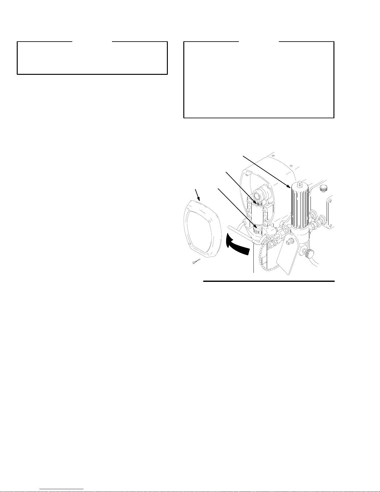
3.
Lubricate the bearing housing (69) after each 100
hours of operation. Relieve the pressure. Remove
the front cover (49). Fill the cavity in the bearing
housing with SAE 10, non-detergent oil. See Fig.
6.
on page 4 whenever
, just enough to stop leak
. Use a round punch or a
, follow the
. Relieve the
CAUTION
T
o prevent serious damage to the pump, which can
result in poor sprayer performance and costly
repairs, follow these precautions.
Do not allow water or any type of paint to
freeze in the sprayer or the pressure control.
Always flush with a compatible solvent and then
flush again with mineral spirits when you are
done spraying.
-
-
.
6.
Coil the hose and hang the hose on the hose rack
when storing the sprayer
66
69
216
49
, even for overnight.
For very short shutof
4.
tube in the paint, relieve the pressure, and clean
the spray tip.
5.
Flush the sprayer at the end of each work day
final flush should be mineral spirits. See page 15.
f periods, leave the suction
. The
Fig. 6
14
307-785
Page 15
Flushing
NOTE:
*Use this category for flushing a brand new sprayer and flushing after storage.
System has
this fluid in it:
*Oil-based
solvent or paint
Oil-based
solvent or paint
Oil-based
solvent or paint
Water or waterbased paint
Water or waterbased paint
Water or waterbased paint
Use this chart to determine the required order for flushing the sprayer
Next fluid to be
sprayed.
Oil-based paint –
new color
W
ater-based paint
Prepare the
sprayer for
storage
W
ater-based paint
– new color
Oil-based paint
Prepare the
sprayer for
storage
Flush 1 Flush 2 Flush 3
Use mineral
spirits.
Use mineral
spirits.
Use mineral
spirits.
Use warm
soapy water
Use warm
soapy water
Use warm
soapy water
Flushing order:
none none
Use warm
soapy water
none none
Use clean
.
water.
Use clean
.
water.
Use clean
.
water.
Use clean
.
water.
none
Use mineral
spirits.
Use mineral
spirits.
.
Follow this step before
you use or store the
sprayer.
Prime the sprayer with oilbased paint.
Prime the sprayer with
water-based paint.
Relieve the pressure.
Leave drain valve open.
Prime the sprayer with
water.
Prime the sprayer with oil.
Relieve the pressure.
Leave drain valve open.
CAUTION
Never allow water to freeze in the pressure control.
If water freezes in the pressure control, it may be
seriously damaged and the sprayer may not start.
Always pump the water out with mineral spirits
before the water could freeze in the pressure con
trol.
-
WARNING
T
o reduce the risk of static sparking and splashing
when flushing, always remove the spray tip from
the gun and hold a metal part of the gun firmly to
the side of a grounded metal pail.
WARNING
T
o reduce the risk of a serious injury
Pressure Relief Procedure
you are instructed to relieve the pressure.
on page 4 whenever
, follow the
4.
Put the suction tube into a grounded metal–pail
with 1/2 gallon (2 liters) of a compatible solvent.
5.
Start the sprayer
still in the sprayer
container until the next fluid appears, then trigger
the gun back into the fluid you are pumping. Circu
late the flushing fluid for a few of minutes to thor
oughly clean the system.
6.
Do not run the pump dry for more than 30 seconds
to avoid damaging the pump packings!
7.
Relieve the pressure. Lock the gun trigger safety
8.
Unscrew the filter bowl (B) and reinstall the clean
screen (C). Install the bowl and hand tighten it.
C
. See page 12. T
, trigger the gun into another
B
o save the fluid
A
-
-
.
1.
Relieve the pressure.
2. T
urn the pressure–adjusting knob (A) fully counter
clockwise to the minimum pressure.
3.
Remove the spray tip from the gun. Remove the
filter bowl (B) and the screen (C), but leave the
support (D) in place. Install the bowl without the
screen. See Fig. 7
.
Fig. 7
D
74
307-785
15
-
Page 16

Troubleshooting
WARNING
T
o reduce the risk of a serious injury
Pressure Relief Procedure
on page 4 whenever
you are instructed to relieve the pressure.
, follow the
Check everything in the charts before disassembling the sprayer
1 The sprayer will not operate.
PROBLEM WHAT TO CHECK
If check is OK, go to next check
1..
Check these basic fluid
pressure
Check these basic
mechanical problems.
Check these basic electrical problems.
problems.
Check the pressure setting. The motor will not
operate if the pressure is at the minimum set
ting (fully counterclockwise).
2.
Check for a clogged spray tip. Refer to the
separate gun or tip instruction manual.
1.
Check
for frozen or hardened paint in the
(76)
and/or the pressure control tube. Use a
screwdriver to manually rotate the fan at the
back of the motor
2.
Check the pump’
pin must be completely pushed into the con
necting rod (68), and the retaining spring (42)
must be firmly in groove of connecting rod.
Fig. 29, page 36.
3.
Check for damage to the motor
drive housing (67). See page 33. T
ally rotate the fan.
1. Check the sprayer’
ton to be sure it has not popped up.
. See page 22.
s connecting rod pin (43). The
. Remove the
ry to manu
s circuit breaker (309) but
.
pump
See
WHA
T T
O DO
When check is not OK refer to this column
1.
-
-
-
Slowly increase the pressure setting to see
if the motor starts.
2.
Relieve the pressure. Refer to the separate
gun or tip instruction manual for tip cleaning.
1.
Thaw the pump. Plug in the sprayer and
turn on the sprayer
sure to see if the motor starts. If the motor
doesn’t start, see NOTE 1, below
2.
Push the pin into place and secure it with
the spring retainer
3.
Replace the motor (73) if the fan won’t turn.
-
See page 34 .
1.
Depress the button to reset. If the circuit
breaker continues to open, see the section
“There is an electrical short.” on page 21.
. Slowly increase pres-
.
.
2.
Check the electrical supply with a volt meter
The meter should read 105 to125 V
3.
Check the extension cord for visible damage.
Check the outlet of the extensions cord with a
volt meter or a test lamp.
4.
Check the power cord (31
as broken insulation or wires.
5.
Check the motor brush leads, the terminals
and the brush length. The brush length should
be at least 1/2 inch (12 mm). See page 25.
NOTE 1:
thawed completely
in the sprayer
trol).
Thaw the sprayer in a warm area if water or water-based paint has frozen in it. Do not try to start the sprayer until it has
. If the bourdon tube was not damaged by the freezing, the pump should operate. If the paint hardened or dried
, the pump packings or the bare pressure control must be replaced. See page 36 (pump) or page 29 (pressure con
2 The motor will not operate.
1.
Diagnosing
board indicator lamps.
The normal condition is
red lamp on, clear lamp
on
when the board is
telling the pump to run.
Follow the
Relief Procedure
Warning.
on page 17.)
the circuit
Pressure
(Continued
Check the leads from the bridge (308) to the
motor to be sure the leads are securely fas
tened and properly mated.
2.
Check the G1 and G2 connections between
the circuit board (23) and the bridge (308) for
damage or loose terminals.
AC.
1) for damage such
-
.
2.
Reset the building circuit breaker; replace
the building fuse. T
3.
Replace the extension cord.
4.
Replace the power cord. See page 26.
5. Tighten the terminal screws; replace the
brushes. See page 25.
1.
Replace any loose terminals. Crimp the
leads. Be sure male terminal blades are
straight and firmly connected to mating part.
2.
Clean circuit board male terminals. Replace
loose or damaged terminals. Securely re
connect leads.
ry another outlet.
-
-
Page 17

3 The motor will not operate.
Conditi
A
Refer to the wiring dia
meter
to the terminal
, not
PROBLEM WHAT TO CHECK
If check is OK, go to next check
Remove the gun from
the hose. Remove the
pressure control cover.
Check for a faulty condi
tion of the circuit board
lamps.
on
Both lamps on, but the
pump won’t operate
and the motor is not
operating.
1.
Check the leads from the bridge (308) to the
motor to be sure the leads are securely fas
tened and properly mated.
-
-
2.
Check the G1 and G2 connections between
the circuit board (23) and the bridge (308) for
damage or loose terminals.
3.
Check for loose connections and terminals on
the motor brushes. See page 25.
4. Check both
length should be at least 1/2 inch (12 mm)
long. See page 25.
5.
Check for a broken or a misaligned motor
brush spring. The rolled portion of the spring
must rest squarely on top of the brush. See
page 25.
6.
Check to see if the motor brushes are binding
in the brush holders. See page 25.
7.
Check the motor’s commutator for burn spots,
gouges, and extreme roughness. See page
25.
of the the brushes. The brush
WHA
T T
O DO
When check is not OK refer to this column
1.
-
Replace any loose terminals. Crimp the
leads. Be sure male terminal blades are
straight and firmly connected to mating part.
2.
Clean circuit board male terminals. Replace
loose or damaged terminals. Securely re
connect leads.
3. T
ighten terminal screws. Replace brushes if
leads are damaged. See page 25.
4.
Replace brushes. See page 25.
5.
Replace spring if broken. Realign spring
with brush. See page 25.
6.
Clean the brush holders, using a small
cleaning brush. Align the brush leads with
the slot in the brush holder
brush movement.
7.
Remove the motor and have a motor shop
resurface the commutator
page 34.
-
to assure vertical
, if possible. See
Condition B:
Both lamps are of
f.
Refer to the wiring dia
gram on page 18 to
identify the test pointS
(TP).
NOTE:
meter
to
disconnect from the ter
minal.
Connect the volt
to the terminal
the wire which you
, not
8.
Use an armature tester or perform the sping
test to check the motor armature for electrical
shorts. See page 22.
9.
Check the bridge (308) by substituting it with a
good bridge or performing the bridge test. See
page 23.
CAUTION:
the
motor armature is determined to be good. A
bad
bridge.
1.
Check the circuit breaker (309) button to be
sure it has not popped up.
Do not perform this check until
armature will immediately burn out a good
-
2.
Check the power cord (311). Disconnect the
TP6 female (neutral) and the TP1 female. Con
nect a volt meter to these leads. Plug in the
sprayer
. The meter should read 105 to 125
V
AC. Unplug the sprayer
3. Check the ON/OFF switch (303). Disconnect
-
the TP2 and connect the volt meter to the TP6
female and the TP2 male. Plug in and turn on
the sprayer
VAC. T
nect theTP2.
4.
Check the jumper wire (306). Disconnect the
TP3. Connect a volt meter between TP6 fe
male and TP3 female. Plug in and turn on the
sprayer
VAC. T
nect theTP3.
. The meter should read 105 to 125
urn of
f and unplug the sprayer
. The meter should read 105 to 125
urn of
f and unplug the sprayer
. Reconnect the TP1.
. Recon
-
. Recon
8.
Replace the motor
9.
Replace the bridge. See page 27.
1.
Depress the button to reset the circuit
breaker
. If circuit breaker or fuse continues
to open, see, “There is an electrical short.”
on page 21.
2.
Replace the power cord. See page 26.
-
3.
Replace the ON/OFF switch. See page 26.
-
4.
Replace the jumper wire. See page 26.
-
. See page 34.
5.
Check the circuit breaker (309). Connect a volt
meter between TP6 female and TP4. Plug in
and turn on the sprayer
read 105 to 125 V
sprayer.
. The meter should
AC. T
urn of
f and unplug the
5.
Replace the circuit breaker
. See page 27.
307-785
17
Page 18

2. The motor will not operate. (Continued)
(TP)
PROBLEM WHAT TO CHECK
If check is OK, go to next check
WHA
T T
O DO
When check is not OK refer to this column
Condition B
(continued)
Both lamps are off
Refer to the wiring
diagram below to
identify the test
points
NOTE:
have
connections:
TP9
TP13
TP15
.
These leads
interchangeable
and
TP10
and
TP14
and
TP16
6.
Check the motor’s thermal cutout switch. Connect a
volt meter between TP6 female and TP9 female.
Plug in and turn on the sprayer
read 105 to 125 V
AC. T
. The meter should
urn of
f and unplug the
sprayer.
7.
Check the microswitch (302). Reconnect the TP6
connectors. Connect the volt meter to TP15 male
and TP4. The meter should read 50–125 V
8.
Inspect the microswitch (302) button. The adjust
AC.
ment stud should not depress the button when the
fluid pressure is zero. Depress the button with a
small screwdriver; an audible click indicates that the
microswitch is in the normal position.
9.
Check the microswitch (302) continuity with an ohm
meter
.
Be sure the sprayer is unplugged!
The meter
should read zero ohms with no fluid pressure in the
sprayer.
10.
Check all the terminals for damage or a loose fit.
Reconnect the TP6 connectors.
11.
Check the circuit board (71) by substituting it with a
good board. See page 28.
WIRING
TP14
TP13
TP6
TP7
DIAGRAM
TP16
BLUE
WHITE
BLACK
YELLOW
RED
302
TP15
TP1
GROUND
WIRE
POWER
BLACK
GREEN
SUPPL
303
AC1
AC2G1G2_+
WHITE
Y CORD
-
6. Allow
the motor to
cool. Correct the cause of
overheating. If the switch remains open after
the
motor cools, check the continuity be
tween the TP9 female and TP10 with ohm
meter
. If open, replace the motor
7.
Clean the male terminals of the
microswitch.
Replace any loose or damaged terminals.
Securely reconnect the leads.
8. The
microswitch is faulty
for
repair
.
9. The
microswitch is faulty
for
repair
.
10.
Replace any damaged terminals and recon
nect the terminals securely
11.
Replace the circuit board. See page 28.
309
TP3
TP4
TP10
TP9
308
TP8
MOTOR
LEADS
MOTOR
THERMAL SWITCH
. Return the sprayer
. Return the sprayer
.
-
-
.
-
Condition C
The red lamps are
on.
The clear lamp is
off.
1.
Check the circuit board (71) by removing it from the
box
without
disconnecting the wires; see page 28
for the procedure.
WARNING: Turn on the sprayer just long enough to
check the lamp condition, then shut of
The procedure in Step 1 could allow the sprayer to
Unplug the sprayer!
over–pressurize.
WARNING: T
o reduce the risk of an electric shock,
handle the circuit board by the edges only! Do not al
low any metal objects to come in contact with the cir
cuit board.
Plug in and turn on the sprayer
lamp should be on now
sprayer.
2
Check bourdon tube flag (B) and the position of the
detector
T
. Reinstall the circuit board (see page 28).
urn the pressure setting to maximum; the flag
should extend less than half way into the optical
detector slot from the bottom.
18
307-785
. T
f the sprayer
. The clear–colored
urn of
f and unplug the
1.
Replace the circuit board. See page 28.
71
.
B
A
-
-
2.
Perform the pressure control adjustment to
see if that corrects the problem. See page
30. If not, replace bare pressure control
(301). See page 29.
01222
Page 19

4 The fluid output is low.
PROBLEM WHAT TO CHECK
If check is OK, go to next check
The fluid output is low
.
1.
Check for worn spray tip. 1.
2.
Check to see that the pump does not continue
to stroke when the gun trigger is released.
in and turn on the sprayer
rigger the gun briefly
T
the trigger safety. Relieve the pressure, turn of
and unplug the sprayer
3.
Check the electrical supply with a volt meter
The meter should read 105–125 V
4.
Check the extension cord size and length; it
must be at least 12 gauge wire and no longer
than 150 ft.
5.
Check the G1 and G2 leads from the bridge
(308) to circuit board (71) for damaged or
wires
or connectors. Refer to Fig. 17, page 27.
6. Check
7.
stall pressure. Refer
Adjustment
Check bridge (308) + and – leads and termi
nals to motor
minals for signs of overheating. See page 27.
on page 30.
. Inspect wiring insulation and ter
. Prime the sprayer
Plug
, then release and lock
.
AC.
loose
to Pressure Control
WHA
T T
O DO
When check is not OK refer to this column
Follow
Pressure Relief Procedure W
ing
then replace tip. See your separate gun
or tip manual.
2
Service pump. See pages 37.
.
f
.
3..
Reset building circuit breaker; replace build
ing fuse. Repair electrical outlet or try an
other outlet.
4.
Replace with a correct, grounded extension
cord.
5.
Clean circuit board male terminals. Replace
loose or defective lead terminals. Securely
reconnect lead terminals to board.
6.
Perform pressure control adjustment. See
page 30.
-
7.
Be sure male terminal blades are centered
-
and firmly connected to female terminals.
Replace any loose terminal or damaged wir
ing. Securely reconnect wires to bridge.
arn-
-
-
-
8.
Check for loose motor brush leads and termi
nals. See page 25.
9.
Check for worn motor brushes which should be
1/2” minimum. See page 25.
10.
Check for broken and misaligned motor brush
springs. Rolled portion of spring must rest
squarely on top of brush.
11.
Check motor brushes for binding in brush hold
ers. See page 25.
12.
Check circuit board (71) by substituting with a
good circuit board. See page 28.
13.
Check motor armature for shorts by using an
armature tester (growler) or perform spin test.
See page 22.
14.
Check bridge (308) by substituting with a good
bridge or by performing the bridge test. See
page 23 or 27.
CAUTION:
mature is determined to be good. A bad arma
ture will immediately burn out a good bridge.
Do not perform this check until ar
-
8. T
ighten terminal screws. Replace brushes if
leads are damaged. See page 25.
9.
Replace brushes. See page 25.
10.
Replace spring if broken. Realign spring
with brush. See page 25.
-
11.
Clean the brush holders, remove carbon
dust with a small cleaning brush. Align the
brush lead with the slot in the brush holder
to assure unhindered vertical brush move
ment.
12.
Replace the circuit board. See page 28.
13.
Replace the motor
14.
Replace the bridge. See page 27.
-
-
. See page 34.
-
Page 20

5 There is no fluid output.
PROBLEM WHAT TO CHECK
If check is OK, go to next check
The motor operates and
the pump cycles.
The motor operates but
pump
the
does not cycle.
1.
Check paint supply
2.
Check for clogged intake strainer
3.
Check for loose suction tube or fittings.
4.
Check to see if intake valve ball and piston ball
are seating properly
5.
Check for leaking around throat packing nut
which may indicate worn or damaged pack
ings. See page 37.
1. Check
6.
7.
displacement pump connecting rod pin
(43). See Fig. 29, page 36.
Check connecting rod assembly (68) for dam
age. See page 32.
Be sure crank in drive housing rotates; plug in
sprayer and turn on briefly to check. T
and unplug sprayer
. 1.
. 2.
. See page 37.
-
-
urn of
. See page 33.
f
WHA
T T
O DO
When check is not OK refer to this column
Refill and reprime pump.
Remove and clean, then reinstall.
3. T
ighten; use thread sealant or sealing tape
on threads if necessary
4.
Remove intake valve and clean. Check
balls and seats for nicks; replace if neces
. See page 36. Strain paint before using
sary
to remove particles that could clog the
pump.
5.
Replace packings. See page 37. Also check
piston valve seat for hardened paint or nicks
and replace if necessary
ing nut/wet-cup.
1.
Replace pin if missing. Be sure retainer
spring (42) is fully in groove all around con
necting rod. See Fig. 29, page 36.
2.
Replace connecting rod assembly
page 32.
3.
Check drive housing assembly for damage
and replace if necessary
.
. T
ighten the pack
. See
. See page 33.
-
-
-
6 There
PROBLEM WHAT TO CHECK
are excessive fluctuations of the pressure.
If check is OK, go to next check
There are variations in
the spray pattern.
1.
Be sure both G1 and G2 leads from bridge
(308) to circuit board (71) are firmly connected.
See Fig. 17, page 27.
2.
Check maximum working pressure adjustment.
Refer to Pressure Control Adjustment on page
30.
3.
Check bourdon tube flag (B) and the detector
(A) position. T
mum; flag should not drag or bind in optical
detector slot of circuit board (71).
4.
Check circuit board (71) by substituting with a
good board. See page 28.
5.
Check section 4 on page 19.
urn pressure setting to maxi
71
A
B
WHA
T T
O DO
When check is not OK refer to this column
1. Reconnect securely
2.
Perform pressure control adjustment. See
page 30.
3.
-
Carefully bend flag into alignment with de
tector slot to see if that corrects problem. If
not, replace bare pressure control assembly
(301). Perform pressure control adjustment
after reassembly
Replace circuit board. See page 28.
. See page 27.
.
-
Page 21

7 The motor is hot and operates intermittently.
An electrical short in any part
immediately. Correctly diag
PROBLEM WHAT TO CHECK
If check is OK, go to next check
The motor is hot and operates
intermittently.
1.
Determine if sprayer was operated at high
pressure with small tips, which causes low
motor RPM and excessive heat build up.
2.
Be sure ambient temperature where sprayer
is located is no more than 90F and sprayer
is not located in direct sun.
3. Determine
ized,
time.
if was sprayer turned on,
but not operating for long periods of
8 There is an electrical short.
PROBLEM WHAT TO CHECK
If check is OK, go to next check
The building’s circuit breaker
opens as soon as the sprayer
is turned on.
switch
An electrical short in any part
of the motor
which is connected to the out
put side of the bridge, will
cause the bridge to burn out
immediately. Correctly diagnose and repair all the electri
cal shorts before checking
and replacing the bridge.
CAUTION
’s power circuit,
1.
Check all electrical wiring for damaged insu
lation, and all terminals for loose fit or dam
age. Also check wires between pressure
control and motor which are encased in con
duit (1). See page 34.
2.
Check for missing inspection plate gasket
-
(see page 25), bent terminal forks or other
metal to metal contact points which could
-
cause a short.
-
3.
Check motor armature for shorts. Use an
armature tester (growler) or perform spin
test. See page 22. Inspect windings for
burns.
pressur
WHA
T T
O DO
When check is not OK refer to this column
1.
Decrease pressure setting or increase tip
size.
2.
Move sprayer to shaded, cooler area if
possible.
-
3T
urn of
f sprayer whenever you stop
spraying for a while and relieve fluid pres
sure.
WHA
T T
O DO
When check is not OK refer to this column
-
1.
Repair or replace any damaged wiring or
-
terminals. Securely reconnect all wires.
-
2.
Correct faulty conditions.
3.
Replace motor
. See page 34.
-
The building’
opens as soon as the sprayer
is plugged into an outlet and
the sprayer is NOT turned on.
The sprayer circuit breaker
opens after the sprayer oper
ates for 5 to 10 minutes.
s circuit breaker
4.
Check bridge (308) by substituting with a
good bridge or by performing bridge test.
See page 23 or 27.
CAUTION:
ture is determined to be good. A bad arma
ture will immediately burn out a good bridge.
1.
Check section 1, “The sprayer will not oper
ate.”, on page 16.
2. Check ON/OFF switch (302) See page 26.
Do not check bridge until arma
Be sure the sprayer is unplugged!
nect wires from switch. Check switch with
ohmmeter
with the ON/OFF switch OFF
the switch ON.
CAUTION:
the bridge out immediately
causes the ON/OFF switch to fail in the
closed mode.
1.
Check electrical supply with volt meter
ter should read 105 to 125 V
-
2.
Check tightness of pump packing nut. Over
tightening tightens packings on rod, restricts
pump action, and damages packings.
3.
Check maximum working pressure adjust
ment.
. The reading should be infinity
, and zero with
A short in the motor circuit burns
, which usually
AC.
Discon-
. Me
4.
Replace bridge. See page 27.
-
-
-
2.
Replace ON/OFF switch. See page 26.
-
1.
If voltage is too high, do not operate
sprayer until corrected.
-
2.
Loosen the packing nut. Check for leak
ing around the throat packings. Replace
the pump packings, if necessary
page 36.
-
3.
Perform pressure control adjustment. See
page 30.
-
. See
4.
After determining that there is no short in
system, reset circuit breaker button.
4.
If circuit breaker continues to open (but
ton pops up), replace the circuit breaker
See page 27.
307-785
.
21
Page 22

Spin
WARNING
To
reduce the risk of a serious injury
Pressure Relief Procedure
you are instructed to relieve the pressure.
Use the spin test to check the armature, the motor
windings, and the electrical continuity of the motor
brushes.
on page 4 whenever
Set up the spin test.
1. Relieve
2.
Remove the drive housing. See page 33.
3.
Remove the pressure control cover
(59), the fan cover (F), and both of the inspection
covers (J). See Fig. 8.
4.
Disconnect the two leads going from the motor to
the bridge (308). See Fig. 9.
the pressure.
Test the armature for an electrical short
circuit.
1. Relieve
the pressure.
, follow the
, the shield
T
est
Fig. 8
59
F
J
01224
2.
Quickly and manually turn the motor fan. If there
are no electrical shorts, the motor will spin two or
three revolutions before completely stopping. If the
motor does not spin freely
cally shorted and the motor must be replaced. See
page 34.
, the armature is electri
Test for electrical continuity between
the armature, the brushes, and the motor
wiring.
1. Relieve
2.
Connect the two, black motor–leads together with
a test lead.
3.
Manually turn the motor fan at about two revolu
tions per second. If there is uneven turning resis
tance or no turning resistance when turning the
fan, check the motor brush area. Repair or replace
parts that are loose, worn or damaged. See page
25. If there is still a problem with the turning resis
tance, replace the motor
the pressure.
-
. See page 34.
-
71
302
-
Fig. 9
-
303
309
308
01225
Page 23

Bridge
WARNING
To
reduce the risk of a serious injury
Pressure Relief Procedure
on page 4 whenever
you are instructed to relieve the pressure.
Remove the bridge from the pressure control. Perform
this test to determine if the bridge is functional. See
the
Bridge Replacement
tester
, such as multi-meter
on page 27. Use a continuity
, set on the X1 ohms scale.
Perform all the tests in the chart. If the bridge fails
even one test, it must be replaced.
, follow the
T
est
In T
ests 4, 5 and 6, connect the + and – meter wires
as indicated, check continuity
, then switch the meter
wire connections and check continuity again. There
should be NO continuity one way and YES continuity
the other way
In T
ests 7 and 8, connect the meter wires as indicated
by the black dots. T
.
ouch the indicated “G” wire to one
meter wire and then to the other meter wire. There
should be NO continuity one way and YES continuity
the other way
CONTINUITY
.
BRIDGE
WIRES
G2 G1 – + AC1 AC2
Fig. 10 shows the position of the wires on the bridge.
Using the chart at the right, connect the meter wires as
indicated by the black dots for each test, and then
check the continuity
Fig. 10
In T
ests 1, 2 and 3, there should be NO continuity
.
AC1
G1 –
AC2 G2
+
.
NO TEST
NO
NO
YES
NO
YES
NO
YES
NO
YES
NO
NO
YES
OR
OR
TEST 2
TEST 3
TEST 4
TEST
TEST
6
TEST 7
TEST 8
1
5
Page 24

General
Repair Information
WARNING
To
reduce the risk of a serious injury
Pressure Relief Procedure
you are instructed to relieve the pressure.
on page 4 whenever
, follow the
CAUTION
T
o reduce the risk of a pressure control malfunc
tion, follow these precautions.
Use needle–nose pliers to disconnect the wires.
Be sure the flat blade of the insulated male con
nector is centered in the wrap-around blade of
the female connector
Route the electrical wires carefully through the
center of the U-shaped bourdon tube. A
interference from the circuit board and between
the pressure control and cover
.
void
.
WARNING
T
o reduce the risk of a serious injury
electric shock or a burn, follow these precautions
when repairing the sprayer
Do not touch any moving parts or electrical
parts with your fingers or a tool while inspecting
the repair
Shut of
soon as you complete the inspection.
Reinstall all of the covers, gaskets, screws, and
washers before operating the sprayer
Do not touch the motor or the drive housing dur
ing operation. These parts may be very hot.
A fire or an explosion could result if flammable
fluids are spilled on a hot, bare motor
Always have the motor shield in place during
regular operation.
.
f the sprayer and unplug the sprayer as
.
, including
.
.
These tools are needed for the repairs.
Phillips screwdriver
Small, flat–blade screwdriver
Needle–nose pliers
Plastic mallet
Adjustable wrench
Adjustable, open-end wrench
-
-
-
T
orque wrench
1/4 inch hex–key wrench
3/16 inch hex–key wrench
5/8 inch socket wrench
3/8 inch open–end wrench
1/2 inch open–end wrench
3/4 inch open–end wrench
7/8 inch open–end wrench
High–quality motor oil
Bearing grease
1.
Keep all the screws, nuts, washers, gaskets, and
electrical fittings that are removed during the repair
procedures. These parts are not normally provided
with the replacement assemblies.
2.
Clean and inspect all parts. Replace worn or dam
aged parts. If you are using a repair kit, use all of
the new parts in the kits even if the old parts still
look good.
3. T
est the repair before the regular operation of the
sprayer to be sure the problem is corrected.
4.
Replace the motor shield if it is damaged. The
shield directs air around the motor to help prevent
overheating.
5.
If the sprayer does not operate properly
repair procedure again to verify that everything
was done correctly. If necessary
bleshooting section, pages 16–21, to help identify
other possible problems and solutions.
, refer to the trou-
, review the
-
CAUTION
Do not operate the sprayer without fluid in it for
more than 30 seconds, to avoid damaging the
pump packings.
24
307-785
Page 25

Motor
Brush Replacement
NOTE:
Replace the brushes when they have worn to
about 1/2 inch (10 mm) in length. Check both of the
brushes. A Brush Repair Kit, part number 220–853,
and a new spring clip, part number 110–816, may be
purchased separately
NOTE:
The replacement brushes may last only half as
long as the original brushes. T
.
o maximize the life of the
brushes, operate the sprayer for at least one hour with
out allowing the pump to stroke. See Steps 10 to 12.
WARNING
T
o reduce the risk of a serious injury
Pressure Relief Procedure
on page 4 whenever
you are instructed to relieve the pressure.
1.
Relieve the pressure.
2.
Remove the shield (14). Remove the covers (A)
from both brush inspection ports. See Fig. 1
14
, follow the
1.
10. T
est the brushes.
a.
Remove the connecting rod pin (20) only
. See
page 36.
b. T
urn of
f the sprayer
. T
urn the pressure–control
knob to the minimum setting. Plug in the
sprayer.
-
c. T
urn on the sprayer
. Slowly increase the pres
-
sure until the motor is at the full speed.
d.
Inspect the contact area of the brush and the
commutator
. The arcs should not circle around
the commutator surface.
CAUTION
Do not touch the brushes, leads, springs, or brush
holders while the sprayer is plugged in, to reduce
the risk of an electric shock and a serious injury
Install the brush inspection plates, the gaskets,
11.
and the covers.
12.
Operate the sprayer for at least one hour
install the pump connecting rod pin. See page 36.
.
. Then,
A
Fig. 11
3.
Push in the clip (D) to unhook it, and then pull out
the clip. See Fig. 12.
4.
Loosen the screw (F). Pull away the brush’
trical lead (E), leaving the motor’s electrical lead
(G) in place. Remove the brush (C) and the spring
(B). See Fig. 13.
5.
Inspect the motor’s commutator for excessive pit
ting, burning or gouging. A black color on the com
mutator is normal. If the brushes seem to wear too
quickly
, have the commutator resurfaced by a
qualified motor repair shop.
6.
Install the new brush (C) so its electrical lead is in
the long slot (K) of the brush holder (H). Slide the
terminal of the brush’
s electrical lead (E) under the
washer of the screw (F). Make sure the motor
electrical lead (G) is still connected the at the
screw. T
7.
Place the spring (B) on the brush (C) as shown in
ighten the screw (F). See Fig. 14.
Fig. 14.
s elec
’s
B
C
D
Fig. 12
01227
B
D
C
-
E
Fig. 13
The
spring must coil in
this direction.
The minimum brush
length is 1/2 inch
(10 mm)
F
G
H
J
01227
C
B
D
8.
Push in the clip (D) and hook it. See Fig. 14.
9.
Repeat this procedure for the other side.
Fig. 14
01227
Page 26

Power
WARNING
To
reduce the risk of a serious injury
Pressure Relief Procedure
you are instructed to relieve the pressure.
on page 4 whenever
, follow the
Cord Replacement
308
NOTE:
1.
2.
3.
4.
5.
Refer to Fig. 15 for this procedure.
Relieve the pressure.
Remove the pressure control cover (63).
Disconnect the electrical lead for the power cord
from the ON/OFF switch (303). Disconnect the
white wire going to the bridge (308). Disconnect
the green wire to the grounding screw (343).
Loosen the bushing (328). Remove the power cord
(311).
Install the new power cord (31
order of disassembly
.
On/Off
1) in the reverse
Switch Replacement
WARNING
To
reduce the risk of a serious injury
Pressure Relief Procedure
you are instructed to relieve the pressure.
NOTE:
1.
Refer to Fig. 16 for this procedure.
Relieve the pressure.
on page 4 whenever
, follow the
303
306
343
327
Fig. 15
7.
Install the guard (305). Align the internal tab with
the groove in the threads.
8.
Sprinkle talcum powder on the inside of the boot
(304). Shake out the excess powder
9.
Install the nut and the rubber boot. T
10.
Reconnect all of the wires.
.
ighten the nut.
328
311
63
01225
2.
Remove the cover (63). See Fig. Fig. 15.
3.
Disconnect the upper terminal wire from the micro
switch (302) and the two black wires from the ON/
OFF switch (303). See Fig. 15.
4.
Using a 5/8 inch socket wrench, remove the nut
and rubber boot (304). Remove the switch guard
(305). See Fig. 16.
5.
Remove the ON/OFF switch (303). See Fig. 16.
6.
Install the new switch. The internal tab of the ring
(W) must engage with the vertical groove in the
threads of the switch. The external tab must
engage with the blind hole (D) of the pressure con
trol. See Fig. 16.
-
D
-
Fig. 16
304
305
W
303
01228
Page 27

Bridge
Replacement
WARNING
To
reduce the risk of a serious injury
Pressure Relief Procedure
you are instructed to relieve the pressure.
NOTE:
ure is a faulty motor
ing the bridge to prevent damaging the new bridge.
NOTE:
1.
2.
3.
The most common cause of a bridge fail
.
Check the motor before replac
Refer to Fig. 17 for this procedure.
Relieve the pressure.
Remove the cover (63) of the pressure control.
Disconnect all the wires from the bridge (308).
on page 4 whenever
, follow the
310
309
306
-
-
308
4.
Loosen
Remove the screw (331B). Slide out the bridge.
5.
Install the new bridge (308). Be sure the lock
washers (333) are IN FRONT of the bridge.
T
but do not remove the screw (331A).
ighten the screws (331) securely
.
CAUTION
The lockwashers (333) must be in front of the
bridge to avoid overheating, which will cause the
bridge to fail. See the detail in Fig. 17.
6.
Connect all the wires properly and route them
carefully.
331A
-
303
G1
G2
Fig. 17
Circuit
63
Breaker Replacement
WARNING
To
reduce the risk of a serious injury
Pressure Relief Procedure
you are instructed to relieve the pressure.
NOTE:
1.
2.
3.
Refer to Fig. 17 for this procedure.
Remove the cover (63).
Use a small screwdriver to slide the terminal of
the circuit breaker (309).
Disconnect the black wire (306) between the circuit
breaker (309) and the switch (303).
on page 4 whenever
, follow the
f of
331B
333
332
01225
4.
Use a 5/8 inch socket wrench to loosen the nut
and the boot (310) on the circuit breaker
5.
Push down on the top of the circuit breaker (309)
and pull it out of the pressure control.
6.
Install the new circuit breaker in the reverse order
of disassembly
.
308
.
CAUTION
Do not allow the contacts of the circuit breaker to
touch the bourdon tube, which will cause an electri
cal short. Firmly tighten the nut on the circuit
breaker to prevent the circuit breaker from turning.
01225
01229
-
Page 28
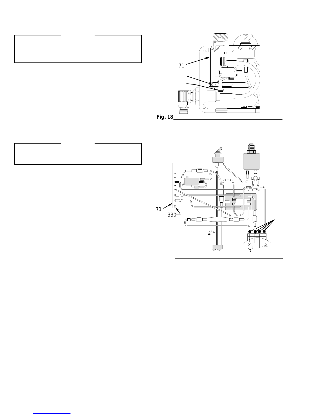
Circuit
Board Replacement
WARNING
To
reduce the risk of a serious injury
Pressure Relief Procedure
you are instructed to relieve the pressure.
NOTE:
1.
2.
3. T
Refer to Fig. 18 and 19 for this procedure.
Relieve the pressure.
Remove the cover from the pressure control.
urn the pressure to the minimum setting to
release the spring tension on the board. Be sure
that only three or four threads on the shaft of the
pressure–control knob are exposed below the
pressure–adjustment nut (S). Loosen the nut, if
necessary.
on page 4 whenever
, follow the
CAUTION
Step 2 is essential to reduce the risk of damaging
the circuit board while removing or installing it.
4.
Disconnect the seven wires from the board. Pay
close attention to where the connections are
made.
5.
Pull out the plastic–tipped pin (330). Push the bot
tom of the circuit board (71) toward the wall of the
pressure control and carefully slide out the board.
6.
Reinstall the new board in the pressure control at
the same angle as it was removed.
71
330
S
Fig. 18
A Blue
B White
C Black
D Yellow
E Red
A
B
C
71
D
E
330
AC1
AC2G1G2_+
-
H
7.
Reconnect all of the wires. Ease the pin (330) into
the retainer
8.
Perform the
30, if you installed a new board.
.
Pressure Control Adjustment,
page
Fig. 19
01221A
28
307-785
Page 29

Pressure
WARNING
To
reduce the risk of a serious injury
Pressure Relief Procedure
you are instructed to relieve the pressure.
on page 4 whenever
, follow the
Control Replacement
Remove the conduit (1).
7.
8.
Remove the three screws (8), lockwashers (10)
and nuts (11). Remove the pressure control.
9.
Remove the screws (22) and the bracket (64).
NOTE:
1.
2.
3.
4.
5.
6.
Refer to Fig. 20 for this procedure.
Relieve the pressure.
Disconnect the hose (70) at the pressure control.
Loosen the nut (38).
Hold the hex of the adapter (341) firmly with a
wrench. Use an adjustable wrench to unscrew the
swivel union (39). Remove the fluid filter (66).
Remove the screws (36) and cover (63). Discon
nect the four motor leads. See Fig. 19.
Remove the circuit board and retain it. See page
28.
CAUTION
T
o avoid damage to the bourdon tube, do not allow
the adapter (341) to turn while installing the new
pressure control. Hold the adapter firmly with a
wrench while screwing in the swivel union (39).
10.
Install the new pressure control in the reverse or
der of disassembly
wires in the elbow (345) of the pressure control.
-
The seal keeps the contaminants from entering the
conduit and the motor
11.
Perform the
30, before regular operation of the sprayer
22
64
. Install the seal (29) around the
.
Pressure Control Adjustment,
8
75
36
33
-
page
.
38
Fig. 20
12
10
11
39
70
344
341
01231A
345
1
29
345
01232
Page 30

Pressure
Control Adjustment
WARNING
Use
extreme caution when performing this adjustment procedure
jury or other serious injury which can result from component rupture, electric shock, fire, explosion, or moving
parts.
to reduce the risk of a fluid injection in
-
This procedure sets the sprayer to 3000 psi (210 bar)
Maximum Working Pressure and sets the overpres
surization switch (microswitch) to approximately 3600
psi (242 bar).
Perform this procedure whenever the pressure con
trol is removed, installed or replaced, and whenever
a new circuit board is installed.
An improper adjustment can cause the sprayer to
over–pressurize and result in component rupture, fire
or explosion. It can also prevent the sprayer from
obtaining the maximum working pressure, resulting in
poor sprayer performance.
WARNING
T
o reduce the risk of a serious injury
Pressure Relief Procedure
you are instructed to relieve the pressure.
These tools are required for the pressure control
adjustment.
3/8 inch nut driver or 3/8 inch socket wrench
1/4 inch open–end wrench
7/16 inch open–end wrench
0 – 5000 psi, oil-filled pressure gauge,
Part No. 102–814
Pail of clean water
Mineral spirits
New spray hose,
3000 psi (210 bar) maximum working pressure,
Part No. 223–541
on page 4 whenever
, follow the
Never try to increase the maximum working pressure
-
-
beyond 3000 psi (210 bar) by performing these ad
justments in any other way
sprayer at higher pressures may result in component
rupture, fire, or explosion. T
ment, however
increased above the normal working pressure.
rarily
Use a
new,
least 3000 psi (210 bar) Maximum W
A used, under–rated hose could develop a high–
pressure leak or rupture.
4.
Place the pump’
water.
5.
Be sure the gun trigger safety is locked.
6.
Plug in the sprayer
, the sprayer pressure must be
50 ft (15.2 m) spray hose rated for at
A
. Normal operation of the
o perform this adjust
orking Pressure
s suction tube in a pail of clean
.
-
-
tempo-
.
1.
Relieve the pressure.
2.
Replace the plug (A) at the top of the fluid filter
with a gauge. Connect the gun to the new spray
hose. Connect the hose to the outlet (B). See Fig.
21.
3.
Remove the cover of the pressure control.
Fig. 21
B
03748A
Page 31

Pressure
Control Adjustment
7. Turn
the pressure–control knob (B) to the
mum
setting (fully counterclockwise).T
sprayer. The pump should not cycle.
22.
If the pump does cycle,
from the bottom of the pressure control. Insert a
3/8 inch nut driver through the opening, and un
screw the adjustment nut (T) just until the sprayer
stops operating.
remove the plug (17)
mini-
urn on the
See Fig.
Adjust the overpressurization switch.
8. Trigger
trol knob clockwise just until the sprayer starts.
Prime the pump and hose.
9.
Slowly turn the pressure–control knob to the maxi
mum setting. Now
light on the circuit board. T
to increase the pressure until the red light goes out
and
(238 – 266 bar).
If the red light does not go out by 3800 psi (266
bar),
until the light goes out.
If the red light goes out before 3400 psi (238
bar),
until the light goes out between 3400 – 3800 psi
(238 – 266 bar).
the gun and
the gauge reads between 3400 –3800 psi
loosen the nut (P) and adjust the stud (Q)
loosen the nut (P) and adjust the stud (Q)
slowly
, observe the gauge and the red
turn the pressure–con
urn the nut (T) slowly
15.
With the pressure–control knob at the
setting, turn on the sprayer
16.
Slowly
turn the pressure–control knob (B) clock
wise to the maximum setting and hold it there. Use
a 3/8 inch nut driver or a socket wrench to slowly
turn the pressure adjustment nut (T) clockwise un
-
-
-
til the gauge reads EXACTL
17. T
urn the pressure–control knob to the minimum
setting. Release the gun trigger safety
gun into a grounded waste–container until the
pressure is relieved. Lock the gun trigger safety
Slowly increase the pressure to verify that the
maximum working pressure is set at 3000 psi (210
bar).
CAUTION
T
o prevent corrosion in the pump,
its to flush the water out of the pump, the hose,
and the gun. Follow the flushing procedure on page
15.
18.
Install the plug (17) in the bottom of the pressure
control. Remove the gauge and reinstall the plug.
Flush out the water with mineral spirits.
B
.
Y 3000 psi (210 bar).
use mineral spir
minimum
. T
rigger the
-
-
.
-
ighten the nut (P) if it was loosened in Step 9.
10. T
11. T
rigger the gun to relieve the pressure. Release
the trigger and lock the gun trigger safety
Step 9 to verify the results.
12.
Install the cover on the pressure control.
. Repeat
Adjust the maximum working pressure.
13. Turn
14.
of
f the sprayer
T
rigger the gun into a grounded waste–container
until the pressure is relieved. Lock the gun trigger
safety.
Use the 3/8 inch nut driver to turn the pressure
adjustment nut (T) counterclockwise, one full turn.
. Unlock the gun trigger safety
P
Q
71
.
T
17
Fig. 22
01243
307-785
31
Page 32

Bearing
1
2
3
49
the roller bearing with grease.
Pack
Oil the inner surface of the bearing housing.
T
orque to 175 in–lb (19 N.m).
1
C
68
2
B
23
3 25
42
43
Housing and Connecting Rod
Replacement
2.
Remove the front cover (49). Disconnect the drain
hose (99) from the pump. Hold a wrench on the
intake valve (223). Unscrew the suction tube. Dis
connect the hose (70).
3.
E
67
69
61
G
Push up the retaining spring (42). Push out the pin
(43).
4.
Loosen the locknut (47). Unscrew the pump (76).
5.
Remove the four screws and lockwashers (25,23).
6.
Lightly tap the lower rear of the bearing housing
(69) with a plastic mallet to loosen it from the drive
housing (67). Pull the bearing housing and the
connecting rod (68) straight of
7.
Remove the pail hanger (61) and install it on the
new bearing housing.
8.
Inspect the crank (E) for excessive wear
the inside of the bronze bearing (B) with a high–
quality motor oil. Pack the roller bearing (C) with a
liberal amount of bearing grease.
f the drive housing.
. Lubricate
-
47
76
99
Fig.
23
WARNING
To
reduce the risk of a serious injury
Pressure Relief Procedure
you are instructed to relieve the pressure.
NOTE:
get the crank (E) in its lowest position. T
crank manually
the blades of the fan.
1.
Stop the sprayer at the bottom of its stroke to
, use a screwdriver to carefully rotate
Relieve the pressure.
on page 4 whenever
, follow the
70
40
223
o lower the
03751
9.
Assemble the connecting rod (68) and the bearing
housing (69).
10.
Clean the mating surfaces of the bearing housing
and the drive housing (69,67).
11.
Align the connecting rod (68) with the crank (E).
Align the locating pins (G) with the holes in the
bearing housing (69). Push the bearing housing
onto the drive housing or tap the bearing housing
into place with a plastic mallet.
CAUTION
Do not use the screws (25) to try to align the bear
ing housing. The bearing housing and drive hous
ing will not align properly
mature wear of the bearing.
12.
Install the screws (25) and the lockwashers (23).
T
orque the screws evenly to 175 in-lb (19 N.m).
13.
Install the pump. See page 38.
14.
Install the remaining parts.
, which will result in pre
-
-
-
Page 33

Drive
Housing Replacement
WARNING
To
reduce the risk of a serious injury
Pressure Relief Procedure
you are instructed to relieve the pressure.
on page 4 whenever
, follow the
CAUTION
Do not drop the gear (51) when removing the drive
housing (67). The gear may stay engaged in the
front of the motor or the drive housing.
Do not lose the balls (9) which are located at each
end of the gear (51). Do not drop the balls between
the gears. The balls, which are heavily covered
with grease, usually stay in place, but could be dis
lodged. If the balls fall into the gears and are not
removed, the balls will seriously damage the drive
housing. If the balls are not in place, the bearings
will wear prematurely
1.
Relieve the pressure.
2.
Remove the cover (49) and the shield (59). Unclip
the drain hose (99) from the pump.
.
4. T
ap the lower–rear portion of the bearing housing
(69) with a plastic mallet to loosen the bearing
housing from the drive housing (67). Pull the
bearing housing and the connecting rod straight of
of the drive housing.
5.
Remove the two screws (26).
6.
Remove the two lower screws (13) and then
remove the two upper screws (16) from the motor
7. T
ap the drive housing with a plastic mallet to
loosen the drive housing from the motor (73). Pull
the drive housing straight of
8.
Apply grease to the gear (51) until the area con
-
tains a total of 4 ounces (1
The grease is supplied with the drive–housing
replacement kit. Be sure the balls (9) are in place.
9.
Place the bronze-colored washer (67b) and then
the silver-colored washer (67a) on the shaft which
protrudes from the big gear in the drive housing
(67).
10.
Align the gears and push the new drive housing
straight on to the front of the motor and the locat
ing pins.
f of the motor
12 grams) of grease.
.
f
.
-
-
3.
Remove the four screws (25).
69
23
25
2
49
11.
Continue to reassemble the sprayer
34
16
20
R
9
51
26
67a
20
13
9
Apply
1
a total of 4 ounces (1
2
T
20
grease to the gear until the area contains
12 grams) of grease.
orque the screw to 175 in–lb (19 N.m).
1
67b
67
E
.
59
99
Fig. 24
03752
Page 34

Motor
Replacement
WARNING
To
reduce the risk of a serious injury
Pressure Relief Procedure
you are instructed to relieve the pressure.
NOTE:
where noted otherwise.
1.
2.
3.
Refer to Fig. 27 for this procedure, except
Relieve the pressure.
Remove the shield (59).
Remove the cover (63) from the pressure control.
Disconnect the four motor leads (A). See Fig. 25.
on page 4 whenever
, follow the
AC1
AC2G1G2
+
_
CAUTION
Always pull the motor leads one at a time to avoid
loosening the terminals, which could result in a bad
connection and poor sprayer performance.
7.
Loosen the nut (31) at the motor
(1) away from the motor
through the conduit, one at a time.
8.
Unscrew the elbow from the motor
9.
Pull the wires through the elbow
10.
Remove the cover (49) from the drive housing.
11.
Remove the two screws (26).
12.
Remove the two lower screws (13) and then
remove the two upper screws (16) from the front of
the motor (73).
13. T
ap the drive housing (67) with a plastic mallet to
loosen it from the front of the motor (73). Pull the
drive housing straight of
. Pull the electrical leads
f of the motor
. Pull the conduit
.
, one at a time.
.
CAUTION
Do not drop the gear (51) when removing the drive
housing (67). The gear may stay engaged in the
A
front of the motor or the drive housing.
Fig. 25
4.
Loosen the nut (345) at the pressure control (75).
5.
Swing the conduit (1) away from the elbow (31).
6.
Remove the seal (29) from around the elbow com
ing into the pressure control. Pull the electrical
leads through the elbow
, one at a time.
Do not lose the balls (9) which are located at each
end of the gear (51). Do not drop the balls between
the gears. The balls, which are heavily covered
with grease, usually stay in place, but could be dis
lodged. If the balls fall into the gears and are not
removed, the balls will seriously damage the drive
housing. If the balls are not in place, the bearings
will wear prematurely
-
14.
Support the motor (75) to keep the sprayer from
tipping. Remove the four screws (8). Lift off the
motor.
.
-
34
307-785
Page 35

Motor
Replacement
15. Install
16.
17.
18.
the new motor (75).
Apply high–quality bearing grease to the gear (51)
until the area contains a total of 4 ounces (1
grams) of grease. Be sure the balls (9) are in
place.
Place the bronze-colored washer (67b) and then
the silver-colored washer (67a) on the shaft which
protrudes from the big gear in the drive housing
(67).
Align the gears and push the drive housing (67)
straight on to the front of the motor and the locat
ing pins.
8
9
67a
51
67b
9
67
73
12
20
-
16
59
19.
Continue to reassemble the sprayer
conduit (1) as you feed wires through the conduit.
Install the seal (29) around the wires in the elbow
(345) of the pressure control. The seal keeps con
taminants from entering the conduit and the motor
See Fig. 26.
29
345
Fig. 26
34
. Rotate the
31
13
26
36
63
.
01232
Fig. 27
99
40
26
20
11
10
70
75
345
1
01236A
Page 36

Removing
WARNING
To
reduce the risk of a serious injury
Pressure Relief Procedure
you are instructed to relieve pressure.
Remove the pump.
69
on page 4 whenever
and Installing a Pump
2.
Hold the pin (43) up to the pin hole in the connect
, follow the
ing rod assembly (68). Continue screwing in the
pump until the pin slides easily into the hole. Back
of
f the pump until the top threads of the pump cyl
inder are flush with the face (A) of the bearing
housing and the outlet nipple (40) is facing straight
back.
3.
Push the spring (42) into the groove all the way
around the connecting rod.
4. T
orque the locknut (47) to 70 ft-lb (97 N.m), using
a 2 inch open–end wrench and a light hammer
WARNING
Be sure the retaining spring (42) is firmly in the
groove of the connecting rod, all the way around, to
prevent it from working loose due to vibration.
-
-
.
42
224
43
47
99
Fig.
28
1.
Flush the pump. Relieve the pressure. Stop the
pump with the piston rod (224) in its lowest posi
tion or carefully rotate the blades of the fan with a
screwdriver to lower the rod.
2.
Hold the intake valve (223) steady with a wrench.
Unscrew the suction tube (86).
3.
Disconnect the hose (70).
4.
Push up the spring (42). Push out the pin (43).
5.
Loosen the locknut (47). Unscrew the pump from
the bearing housing (69).
216
70
40
223
86
Install the pump.
1. Screw
the displacement pump three–fourths of the
way into the bearing housing (69).
04433
-
If the pin works loose, parts could break of
the force of the pumping action. These parts could
be propelled through the air and result in a serious
injury
, sprayer damage or property damage.
f due to
CAUTION
If the locknut (47) loosens during operation, the
threads of the bearing housing (69) will be dam
aged. Be sure to tighten the locknut firmly
ighten the packing nut (216) just enough to stop
5. T
leakage, but no tighter
1/3 full with Graco TSL. See Fig. 29.
Torque
1
Fig. 29
the nut to
70 ft–lb (95 N.m).
68
A
216
. Fill the wet-cup/packing nut
.
47
-
42
43
69
1
03750
36
307-785
Page 37

Displacement
8
Pump Repair
Fig.
30
Fig. 31
205
216
224
219
B
*209
*213
*208
207*
220
221*
204*
202*
223
A
219
04230
04231
NOTE:
An asterisk following a reference number indicates that
the part included in the kit. For the best results, use all
of the parts in the kit, even if the old parts still look
good.
NOTE:
bling the pump. Replace the worn or damaged parts.
Use the Packing Repair Kit, Part No. 222–588.
Clean and inspect the parts after disassem
-
WARNING
T
o reduce the risk of a serious injury
Pressure Relief Procedure
you are instructed to relieve the pressure.
on page 4 whenever
, follow the
Disassemble the Pump.
1. Relieve
2.
Remove the pump. See page 36.
3.
Unscrew the intake valve assembly (A) from the
cylinder (219). Remove all of the parts. See Fig.
30.
4.
If no further service is needed, reassemble the
intake valve assembly
5.
Remove the packing nut (216) and the plug (205).
See Fig. 30.
the pressure.
. Use a new gasket (202*).
224
*225
211
Fig. 32
Fig. 33
*206
210*
212*
215*
203*
214*
222
A
B
218
219
6.
Use a plastic mallet to tap the piston rod (224)
down. Pull the rod out from the bottom of the
cylinder (219). See Fig. 30.
7.
Remove the throat packings and the glands (B).
See Fig. 31.
8.
C
04232
Clamp the flats of the piston rod (224) in a vise.
Loosen the nut (21
(222) from the rod. Remove all the parts from the
piston assembly (C). See Fig. 32.
9.
Remove the sleeve (218), using the sleeve remov
al tool, Part No. 222–586. Clean the sleeve and
the cylinder
.
1). Unscrew the piston valve
-
WARNING
Always use the special sleeve removal tool, Part
No. 222–586, to remove the sleeve. Other tools or
methods could cause the pump to rupture, resulting
002
in serious injury
easily
, return the sleeve and the cylinder to your
Graco distributor for removal.
10.
Screw the large nut (B) of the tool in to the top of
the cylinder (19). Screw down the rod (A) to push
the sleeve out of the cylinder. Remove the tool.
See Fig. 33
. If the sleeve cannot be removed
.
Page 38
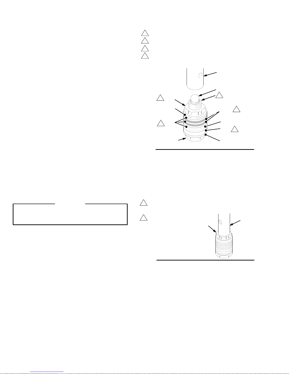
Displacement
Reassemble the Pump.
NOTES:
Install
1.
2. T
the leather and plastic packings exactly as
indicated and as shown in Figures 34 and 38. Incor
rect installation causes the pump to leak and may
damage the packings.
Clean and inspect all sides of the parts. Replace
any parts that are worn or damaged. Those parts
will not seal properly with new parts.
Soak the leather packings in oil before using them.
Stack the backup washer (214), the seal (203*),
and the female gland (215*) on the piston valve
(222). Alternately stack the packings (212*,206*),
and then male gland (210*) on the piston valve
(222). See Fig. 34.
ighten the nut (21
(222). T
orque the nut to 19 ft-lb (27 N.m).
1) against the piston valve
Pump Repair
Torque
1
2
3
-
4
Fig.
5.
Place the flats of the piston rod in a vise.
the nut to 10.5 in-lb (1.2 n.m) to seat the packing.
Loosen the nut and then lightly retighten.
Apply one drop of sealant t othese threads.
The lips of the V–packings must face up.
The lips of the U–cup packing must face down.
211
1
*210
212
4
222
34
224
225*
2
206*
215*
203*
214*
3
4
03178
Note the alignment
(21
1). Maintain this alignment through Step 7.
3.
Place the ball (225) on the piston valve (222). See
of the piston (222) to the nut
Fig. 34.
CAUTION
Step 4 is critical. Follow the procedure carefully to
avoid damaging the packings by overtightening.
4.
Apply one drop of adhesive, supplied, to the
threads of the piston valve assembly
the assembly in to the piston rod just until the nut
(21
1) makes contact with the rod (224). See Fig.
34.
. Hand tighten
6.
Use a wrench to carefully tighten the nut (21
to the piston rod. T
orque the nut to 19 ft-lb (25
N.m). See Fig. 35.
7.
Use two wrenches to maintain the alignment men
tioned in Step 7, above.
Torque
1
2
the nut against the
rod to 19 ft–lb (27 N.m).
Do not allow the nut to
move when installing the
piston valve assembly on
to the rod.
211
Fig. 35
1) on
-
224
01238
Page 39
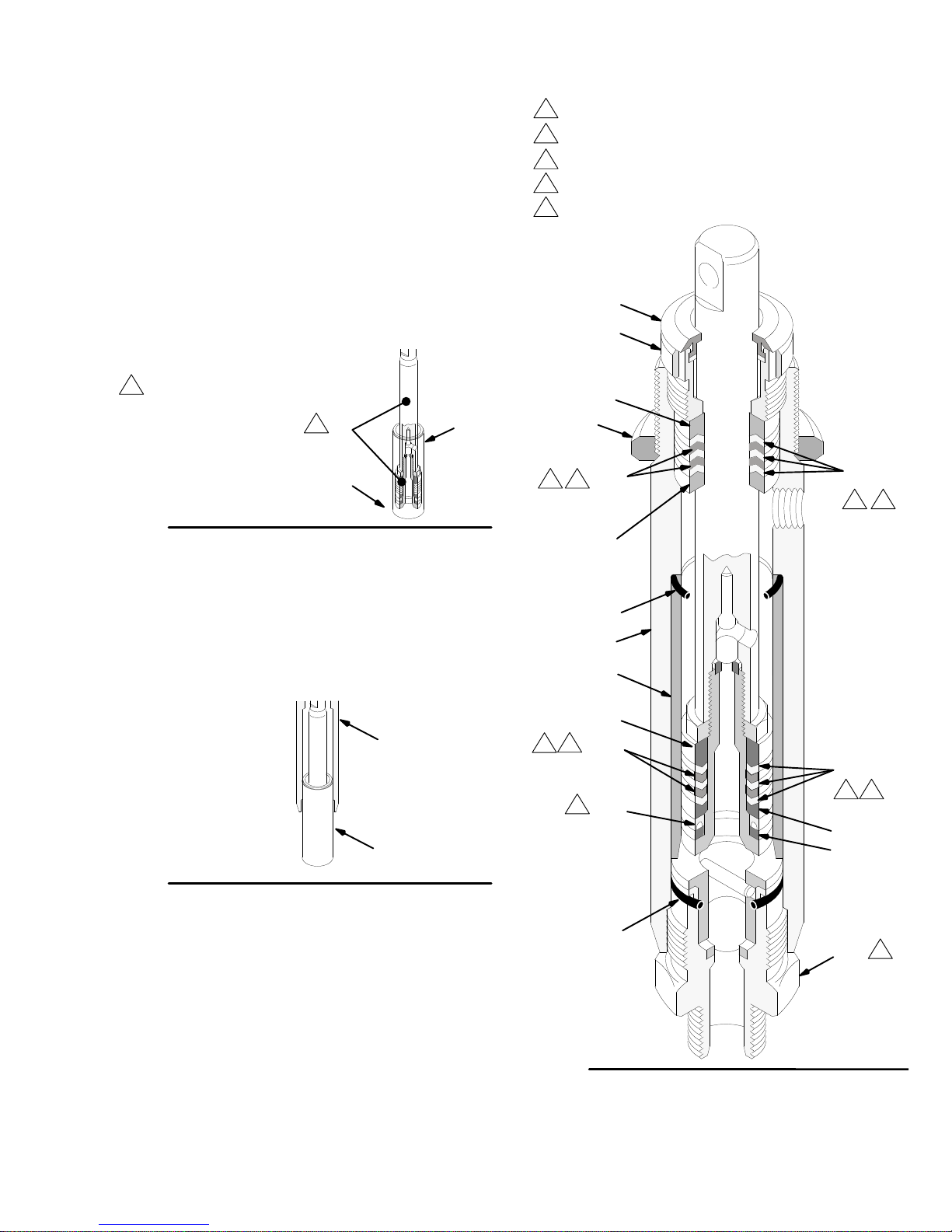
Displacement
Pump Repair
8. Stack
the glands and packings in the top of the
cylinder (219). Be sure to alternate the leather
(207*) and plastic (213) v–packings and stack the
v–packings so the lips face down. See Fig. 38.
9.
Install the packing nut (216) and the plug (205),
but leave the nut loose for now
10.
Oil the piston rod and the packings. Carefully slide
the assembly (A)
into the top of the sleeve
. See Fig. 38.
(218).
NOTE:
The tapered end (B) of the sleeve (218) is the
bottom of it. See Fig. 36.
Oil
the piston rod
1
and the packings.
1
A
B
Fig. 36
11. Place
a new o–ring (217*) firmly in the cylinder
groove. See Fig. 38.
218
0030
Leather
1
2
3
4
5
packings.
Poly packings.
The lips of these packings must face down.
The lips of these packings must face up.
orque the intake valve to 70 ft–lb (95 N.m).
T
205
216
*209
47
*207
1 3
*208
213*
32
12.
Slide the sleeve and piston rod assembly (C)
the bottom of the cylinder (219)
. This is to pre
vent packing damage during reassembly
36.
219
C
Fig. 37
Screw down the cylinder locknut (47) until it is fin
13.
ger tight at the bottom of the external cylinder
threads.
Place the flats of the intake valve (223) in a vise.
14.
Install a new o-ring (202*). Screw the pump cylin
der into the valve. T
Fig. 38.
15.
Install the pump.
orque to 70 ft-lb (95 N.m). See
into
-
. See Fig.
*217
219
218
*210
4
1
*206
212*
4
*203
42
215*
214*
*202
5
223
-
Fig. 38
01197
307-785
39
Page 40

See
page 42 for the pressure control parts.
1
Parts
– Upright Sprayer
41
57
56
77
59
24
61
58
49
25
23
43
98
99
91
65
69
68
67
76
86
53
9
42
47
67b
40
32
51
26
67a
70
20
73
9
97
10
73D
20
11
16
50
10
66
34
66a
34
85
90
34
94
Ref 77
31
8
13
20
21
78
22
33
8
64
75
1
1
63
14
44
55
62
48
89
37
35
Ref 78
19
36
102
100
101
01239A
40
307-785
72
38
12
40
66b
Ref 70
39
74
45
Ref 99
Page 41

Model
231–034, Series D
Includes
items 1 – 99
Parts
– Upright Sprayer
Basic Sprayer
Ref
No. Part No. Description Qty
1 065–099 ELECTRICAL CONDUIT
s
pecify
length when ordering
8 110–963 SCREW
5/16–18 x 3/4
100–069
9
10
100–188
11 100–214
BALL,
NUT
LOCKWASHER,
,
1/4” dia.
,
5/16–18
serrated
”7
unc–2a
12 100–322 LOCKWASHER,
13 100–643 SCREW
,
socket
flange, hex hd,
5/16”
7/16” 1
head, 1/4–20 x 1”
0.8 ft
14 101–242 RETAINING RING 2
16
100–644
17 101–754 PLUG
SCREW,
see
socket head, 1/4–20 x 0.75”
page 42
19 104–811 HUBCAP 2
20 105–510
LOCKWASHER, 1/4” 6
21 106–062 WHEEL 2
22
23 106–115 LOCKWASHER,
24 107–209 SCREW,
25 107–210 CAPSCREW,
26 107–218
27 107–258 TIP,
29 107–447 SEAL,
31 108–460
106–078 SCREW,
no. 6–24 x 3/8”, type “c”
3/8–16 x 1–1/2”
CAPSCREW
1/4–20 x 2.75”
grip,
45_ CONDUIT CONNECTOR
oval head
spring, 3/8”
filh, no. 8–32 x1”
socket head,
,
socket
see
page 42
see
page
2
head,
32 112–746 RETAINER NUT 2
33 108–691 PLUG 2
34 108–865
35 109–032 SCREW,
36 110–037 SCREW,
SCREW,
pan head, no. 8 x 3/8”
pan head, 10–32 x 1/4”
pan head, 10–24 x 1/2”
10
37 110–243 RETAINING RING 2
38
150–513
39 155–665 SWIVEL UNION,
40 162–453 NIPPLE,
41Y 185–952 LABEL,
NUT
,
7/16”
x 3/8 npt(m)
1/4
DANGER,
3/8” npsm swivel
npt(m) x 1/4 npsm
English
42 176–817 RETAINING SPRING 1
43
44Y 177–762 LABEL,
45Y 178–034 TAG,
46Y 185–594 LABEL,
176–818 PIN, headless,
W
ARNING 1
W
ARNING 1
WARNING 1
0.3125” dia x 1.023”
47 178–941 NUT 1
48 111–590 SNAP BUTTON 2
49 188–154 COVER 1
,
50 179–945 ELBOW
1/4–18
special,
npt (m x f)
51 179–961 GEAR REDUCER 1
see
page
52 180–041 PIN
53 187–147
STRAINER 1
55 181–608 LABEL,
56 181–639 LABEL,
57 181–640 LABEL,
58 181–641 LABEL,
59 223-095 SHIELD
1
identification
ID,
motor cover
ID,
motor cover
ID,
front cover
; includes items 41, 46, 56, 57
, left
, right
61 189–918 HANGER 1
62 187–603 SLEEVE 2
63 183–995 COVER 1
Model
231–043, Series B
Includes
items 1 – 102
Complete Sprayer
Ref
No. Part No. Description Qty
64
183–365 BRACKET 1
65 206–994 THROAT SEAL LIQUID,
FIL
66 214–570 FLUID
Includes
2
7
66a 100–040 .PLUG 1
7
66b 162–453 .NIPPLE,
see manual 307–273 for parts
TER
66a and 66b
1/4
npt(m) x 1/4 npsm
67 220–369 DRIVE HOUSING
2
67a 178–967 .WASHER,
2
67b 107–089 .WASHER,
1
68
69
218–034
218–035 BEARING HOUSING
includes
replaceable items 67a and 67b
silver–colored 1
bronze–colored 1
CONNECTING ROD 1
Includes items 32 and 61
70 223–766 HOSE,
cpld 1/4 npsm (f), 29” (715 mm),
4
4
71 218–405
4
72 220–285 CAP 1
73* 222–388
4
2
1
73a 107–267 .TERMINAL,
spring guards both ends
CIRCUIT BOARD,
MOTOR, ELECTRIC
includes
(which are shown on page
and one of item 9
grounded,
replaceable items 73a to 73d
73b 107–504 .TERMINAL,
1
103–885
73c
.TERMINAL,
73dY 185–951 .LABEL,
74 222–198
PRESSURE DRAIN VALVE 1
DANGER,
nylon, 1/4” ID
1
15V 1
female 2
female
wire, female, snap–on
English
75 220–455 PRESSURE CONTROL ASSY
4
4
76 222–580
1
77 222–554 HANDLE 1
see
page
for parts
DISPLACEMENT PUMP
see
page 44 for parts
78 222–555 CART
1
2
85 185–384 BRACKET 2
1
86 185–386 SUCTION TUBE 1
includes replaceable items 58 & 76
89 183–350 WASHER 2
1
90 110–240 SPEED NUT 2
91 181–102 CLIP 1
94 100–020 WASHER 2
97Y 185–955*
LABEL,
DANGER,
French
98 186–494 CLIP 1
99 186–495 DRAIN HOSE 1
100 223–541 HOSE,
1
101 214–701 HOSE,
1
102 220–955 SPRAY GUN
1
grounded, nylon, 1/4” ID,
cpld 1/4 npsm(f), 50 ft (15 m)
spring guards both ends
grounded,
cpld 1/4 npsm(f), 3 ft (.9 m),
spring guards both ends
see
manual 307–614 for parts
nylon, 3/16” ID,
1
1
* These
1
Y
parts are also included in the Motor Brush Repair
Kit, 220–853, which may be purchased separately
Replacement Danger and W
arning labels, tags and cards
are available at no cost.
8
OZ
)
1
1
1
1
1
1
1
1
1
1
1
1
1
1
1
1
1
.
307-785
41
Page 42
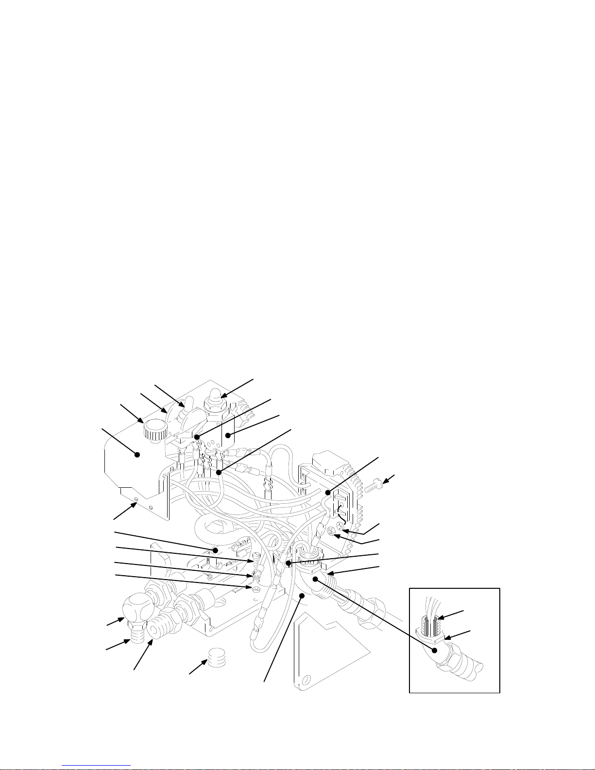
Parts
– Pressure Control
Pressure
Includes
The terminals are included with the circuit board (item 71).
The terminals listed in this parts list are shown on the wiring
diagram on page 43
Ref
No. Part No. Description Qty
302 180–043 MICROSWITCH 1
303 105–679 ON/OFF SWITCH 1
304 105–659 BOOT 1
305 107–255 GUARD 1
306 218–168 JUMPER WIRE 1
308 218–170 RECTIFIER 1
309 107–256 CIRCUIT BREAKER 1
310 107–254 BOOT 1
311 218–169 POWER CORD 1
312 107–268 TERMINAL ADAPTER 1
314 107–267
315 107–293
316 107–264
317 107–396
318 107–262
319 107–260
320 107–266
321 103–885
322 103–886
323 107–265
324 107–263
Control Assembly
all items listed below
.
TERMINAL, female
TERMINAL, female
TERMINAL, male
TERMINAL, male
TERMINAL, female
TERMINAL, female
TERMINAL, female
TERMINAL, male
TERMINAL, female
TERMINAL, female
TERMINAL, female
220–455
, except the terminals.
Part numbers for items 17, 27, 29, 52, 71, 73a, 73b and 73c
are shown in the drawings below and on page are given on
page 41
Ref
No. Part No. Description Qty
325 102–799 RING TERMINAL 1
327 157–021 LOCKW
328 108–295 STRAIN RELIEF BUSHING 1
331 101–273 SCREW
332 100–179 NUT
333 100–718 LOCKW
334 178–797
335 178–035
336 107–261
337 107–503
1
338 107–504
2
341 157–350
1
342 100–840 ELBOW
1
343 100–035 SCREW
1
1
344 162–453
1
345 108–460 CONDUIT CONNECTOR 1
1
3
1
1
.
ASHER, no. 8
, flat hd, no. 10–24 x 5/8”
, hex, no. 10–24 thd
ASHER, no. 10
LABEL, W
LABEL, W
TERMINAL, male
TERMINAL, female
TERMINAL, male
ADAPTER, 3/8 npt(m) x 1/4 npt (m)
, 1/4 npt(m x f)
, slotted
pan hd, no. 8 x 5/16”
NIPPLE, 1/4 npt(m) x 1/4 npsm
Replacement Danger and W
are available at no cost.
ARNING 1
ARNING 1
arning labels, tags and cards
1
2
2
2
2
1
1
1
1
1
1
334,
335
Ref
342
344
301
71
302
343
325
327
305
304
310
303
309
306
308
331
333
332
328
345
29
345
341
42
307-785
17
311
01232
01225
Page 43

Parts
– W
iring Diagram
Circuit
KEY
A Blue
B White
C Black
D Yellow
E Red
F Green,
G
Power cord
H Motor
Thermal switch
J
Board 218–405, 5 W
71
A
B
C
D
E
336
Ref 27,52
319
320
Ground wire
302
75a
ires
317
318
323
316
324
303
304
AC1
AC2G1G2_+
B
C
F
G
309
306
312
322
321 (75c)
337
75b
308
314
323
75a
H
J
307-785
43
Page 44

Model
222–580, Series A
Parts
– Displacement Pump
Includes items 202 to 225
Ref
No. Part No. Description Qty
205
216
224
202* 110–165 PACKING, PTFE
203* 107–093
204* 105–445 BALL 1
205 179–810 PLUG 1
206* 178–939 V–P
207* 178–940 V–P
208* 178–942
209* 178–943
210* 178–944
211
212* 178–964 V–PACKING, plastic 3
213* 178–965 V–PACKING, plastic 3
214* 181–338 BACKUP WASHER 1
215* 178–969
216
218
219 185–21
220
221* 178–938 PIN 1
222
223
224
225* 105–444
*
178–945
179–809
185–213
185–214
218–036
222–437
222–438
These parts are also included in Repair Kit 222–588,
which may be purchased separately
hand to reduce down time.
U–CUP SEAL, polyurethane
ACKING, leather
ACKING, leather
GLAND, male
GLAND, female
GLAND, male
NUT
, hex,
GLAND, female
PACKING NUT 1
SLEEVE 1
1
CYLINDER 1
BALL GUIDE 1
PISTON VALVE 1
INTAKE VALVE 1
PISTON ROD 1
BALL
2
. Keep a repair kit on
209*
1
225*
211
2
2
1
1
1
1
1
*207
213*
208*
*206
219
210*
212*
215*
203*
214*
222
1
202*
218
220
221*
204*
202*
NOTE:
A sleeve removal tool, Part No. 222–586, which is for
use only with pump 222–580, is required for removing the
sleeve from the cylinder
. Purchase the tool separately
.
223
44
307-785
Page 45

Notes
307-785
45
Page 46

Notes
46
307-785
Page 47

Power
Requirements
Motor
Working
Cycles/Gallon (liter) 200 (53).
Maximum
Tip
Power Cord
Inlet
Outlet
Pump
Fluid
Wetted
.
. . . . . . . . . . . . . . . . . . . . . . . . . . . . . . . . . . . . . . . . . . . . . . . . . . . . . . . . . .
Pressure Range
Delivery
Size
.
. . . . . . . . . . . . . . . . . . . . . . . . . . . . . . . . .
.
. . . . . . . . . . . . . . . . . . . . . . . . . . . . . .
Paint Strainer
Paint Filter
Inlet Size
Outlet Size
Parts:
Displacement Pump
Packing
Filter
Material
.
. . . . . . . . . . . . . . . . . . . . . . . . . . . . . .
.
. . . . . . .
.
. . . . . . . . . . . . . . . . . . . . . . . . . . . . . . .
.
. . . . . . . . . . . . . . . . . . . . . . . . . . . . . . . . . . . .
Technical
.
. . . . . . . . . . . . . . . . . . . . . . . . . . . . . . . . . . . . . . .
1
phase, 15 amp minimum or 3500 W
.
. . . . . . . . . . . . . . . . . . . . . . . . . . .
. . . . . . . . . . . . . . . . . . . . . . . . . . . . . . . . . . . . . . . . . . . . . .
.
. . . . . . . . . . . . . . . . . . . . . . . . . . . . . . . . . . .
.
. . . . .
.
. . . . . . . . . . . . . . . . . . . . . . . . . . . . .
16 mesh (1
60 mesh (250 micron), stainless steel screen, reusable
. . . . . . . . . . . . . . . . . . . .
60
190 micron), stainless steel screen, reusable
mesh (250 micron reusable stainless steel screen
Data
120 V
AC, 60Hz,
att generator
0–3000 psi (0 – 210 bar)
1.0 gpm (3.8 liter/min)
one gun – 0.031; two guns – 0.019
(with
latex at 2000 psi (138 bar)
No. 14 awg, 3 wire, 8.5 feet (2.6 m)
3/4 npt(m) with 30 ID chamfer
1/4 npsm from fluid filter
Carbon steel, polyurethane, Delrin
Leather
Aluminum,
, UHMW polyethylene
carbon steel, stainless steel
1 hp, DC
.
NOTE: Delrin
is a registered trademark of the DuPont Co.
Dimensions
Weight
Height 28
Length 26 in. (660 mm).
Width 22.5 in. (572 mm).
(dry w/o packaging)
. . . . . . . . . . . . . . . . . . . . . . . .
. . . . . . . . . . . . . . . . . . . . . . . .
. . . . . . . . . . . . . . . . . . . . . . . . .
.
. . . . . .
95 lb (43 Kg)
in. (71
Graco
1 mm).
TO
PLACE AN ORDER
utor
, or call this number to identify the distributor
closest to you:
FOR TECHNICAL ASSIST
information or assistance regarding the application of
Graco equipment:
Numbers
1–800–367–4023 T
1–800–543–0339 T
Phone
, contact your Graco distrib
oll Free
ANCE,
service repair
oll Free
-
307-785
47
Page 48

Manual
The
bearing housing on the Upright Sprayers has
Change Summary
changed in appearance, but the part number has not
changed. The change in appearance resulted in a
change to the pail hanger which is itemized in the chart
to the right.
Assembly Part
231–034
and
231–043
Sprayers
Status
Delete 32
Add 3261112–746
Old
New
Old
New
Old
New
Ref Part
60
61
4646178–934
4949179–899
70 223–766
No.
110–814
183–035
186–277
189–918
185–954
188–454
235–574
Name
Nut
Bracket
Hanger
Nut
Hanger
Label
Label
Cover
Cover
Hose
Hose
The
WARRANTY
warrants all equipment manufactured by it and bearing its name to be free from defects in material and workmanship on
Graco
the date of sale
warranty
defective, with the exception of defects in parts on the drive train/gear box, which will be repaired or replaced for forty-eight
months from the date of sale and the electric motor (excluding brush replacement, which is routine maintenance) or pressure
control assembly which will be repaired or replaced for twenty-four months from the date of sale. This warranty applies only when
the equipment is installed, operated and maintained in accordance with Graco’
This warranty does not cover
misapplication, abrasion, corrosion, inadequate or improper maintenance, negligence, accident, tampering, or substitution of
non–Graco component parts. Nor shall Graco be liable for malfunction, damage or wear caused by the incompatibility with Graco
equipment of structures, accessories, equipment or materials not supplied by Graco, or the improper design, manufacture, instal
lation, operation or maintenance of structures, accessories, equipment or materials not supplied by Graco.
This warranty is conditioned upon the prepaid return of the equipment claimed to be defective to an authorized Graco distributor
for verification of the claim. If the claimed defect is verified, Graco will repair or replace free of charge any defective parts. The
equipment will be returned to the original purchaser transportation prepaid. If inspection of the equipment does not disclose any
defect in material or workmanship, repairs will be made at a reasonable charge, which charges may include the costs of parts,
labor and transportation.
DISCLAIMERS AND LIMITATIONS
The terms of this warranty constitute purchaser’s sole and exclusive remedy and are in lieu of any other warranties (express or
implied),
liabilities, including product liabilities, based on negligence or strict liability
tial damages or loss is expressly excluded and denied. In no case shall Graco’
Any action for breach of warranty must be brought within two (2) years of the date of sale.
EQUIPMENT NOT COVERED BY GRACO WARRANTY
Graco makes no warranty
respect to accessories, equipment, materials, or components sold but not manufactured by Graco. These items sold, but not
manufactured by Graco (such as electric motor
Graco will provide purchaser with reasonable assistance in making any claim for breach of these warranties.
, Graco will, for a period of twelve months from the date of sale, repair or replace any part of the Ultra equipment proven
including warranty of merchantability or warranty of fitness for a particular purpose,
Graco Warranty and Disclaimers
by an authorized Graco distributor to the original purchaser for use. As purchaser’s sole remedy for breach of this
s written recommendations.
, and Graco shall not be liable for
, and disclaims all implied
warranties of merchantability and fitness for a particular purpose,
, switches, hose, etc.) are subject to the warranty
, any malfunction, damage or wear caused by faulty installation,
and of any non–contractual
. Every form of liability for direct, special or consequen
s liability exceed the amount of the purchase price.
with
, if any
, of their manufacturer
.
-
-
Sales Offices:
Foreign Offices:
Atlanta, Chicago, Dallas, Detroit, Los Angeles, Mt. Arlington (N.J.)
Canada; England; Korea; Switzerland; France; Germany; Hong Kong; Japan
GRACO INC. P.O. BOX 1441
PRINTED
48
307-785
IN U.S.A. 307–785 July
MINNEAPOLIS, MN
, 1986, Revised November
55440–1441
, 1994
 Loading...