

Page 1
Operation,Repair,andParts
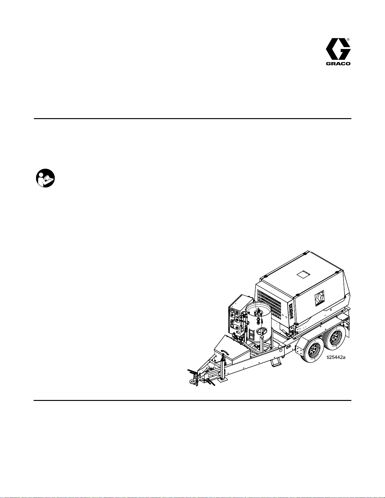
EcoQuip
EcoQuip EcoQuip
Blast
Blast Blast
Vapor
Vapor Vapor
or
hazardous
or or
hazardous hazardous
125 psi (8.6 bar, 0.86 MPa) Maximum
Working Pressure
See page 2 for Model information.
System
System System
abrasive
abrasive abrasive
locations.
locations. locations.
Important
Important Important
Readallwarningsandinstructionsinthismanual.Savethese
instructions.
Vapor
Vapor Vapor
Abrasive
Abrasive Abrasive
334666B
EN
blast
system.
blast blast
system. system.
Safety
Safety Safety
Instructions
Instructions Instructions
For
professional
For For
professional professional
use
only.
Not
use use
only. only.
approved
Not Not
approved approved
for
use
for for
use use
explosive
in ininexplosive explosive
atmospheres
atmospheres atmospheres
PROVENQUALITY.LEADINGTECHNOLOGY.
Page 2

Contents
Contents Contents
Models...............................................................2
RelatedManuals................................................2
Warnings...........................................................3
Notes.................................................................5
SystemComponentIdentication.........................6
EQ200TandEQ400T...................................6
DataTrakControls........................................7
PressureReliefProcedure..................................8
Operation...........................................................9
ChecklistBeforeStarting..............................9
LiftingtheTrailerSystems............................9
ConnectingtheBlastHoseandAir
Hose..............................................10
SettingUptheEquipment.............................11
BlastingTips................................................15
UsingtheWashFeature...............................17
RellingthePotwithAbrasive.......................18
ShuttingDown.............................................19
WinterizingtheEquipment............................21
Troubleshooting..................................................22
TroubleshootingExamples...........................26
Repair................................................................28
RepairingtheMainAirRegulator..................28
FlushingtheDiaphragmValve......................29
RepairingtheDiaphragmValve.....................30
CleaningtheAuto-VentValve.......................31
ReplacingtheDataTrakBattery....................32
ReplacingtheDataTrakFuse.......................33
Parts..................................................................34
EQ200TandEQ400T...................................34
Enclosure....................................................36
Trailers........................................................38
PressurePot................................................41
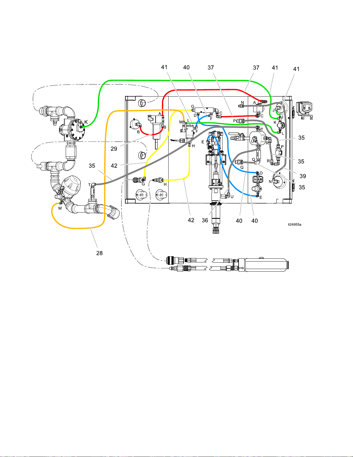
HoseSchematic.................................................42
VaporAbrasiveBlastSystemsand
Accessories..........................................43
EcoQuipSkidSystems.................................43
EcoQuipTrailerSystems..............................43
Mobile/SkidUnits.........................................44
TrailerUnits.................................................44
Hoses.........................................................45
Nozzles.......................................................45
CommonSpareParts...................................46
OtherAccessories........................................46
Dimensions........................................................47
TechnicalSpecications......................................48
Notes.................................................................49
GracoExtendedWarrantyforEcoQuip™
Components.........................................50
Models
Models Models
Part
Part Part
EQ200TEcoQuip200VaporBlastSystem
EQ400TEcoQuip400VaporBlastSystem
Related
Related Related
2
Manuals
Manuals Manuals
Manual
Manual Manual
Number
Number Number
313840DataTrak
333397Pump
334142
334143
334667
Product
Product Product
EQ100M
EQ300M,EQ600M
EQ300C,EQ600C
Description
Description Description
334666B
Page 3
Warnings
Warnings Warnings
Thefollowingwarningsareforthesetup,use,grounding,maintenance,andrepairofthisequipment.The
exclamationpointsymbolalertsyoutoageneralwarningandthehazardsymbolsrefertoprocedure-specic
risks.Whenthesesymbolsappearinthebodyofthismanualoronwarninglabels,referbacktothese
Warnings.Product-specichazardsymbolsandwarningsnotcoveredinthissectionmayappearthroughout
thebodyofthismanualwhereapplicable.
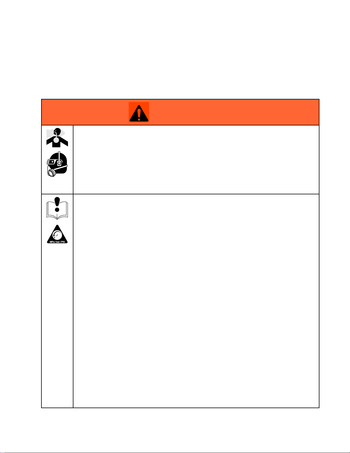
WARNING
WARNING WARNING
DUST
DUST DUST
Useofthisequipmentcanresultinthereleaseofpotentiallyharmfuldustortoxicsubstances
fromtheabrasivebeingused,thecoatingsbeingremoved,andthebaseobjectbeingblasted.
•Foruseonlybysophisticatedusersfamiliarwithapplicablegovernmentalsafetyandindustrial
•Useequipmentonlyinawell-ventilatedarea.
•Wearaproperlyt-testedandgovernmentapprovedrespiratorsuitableforthedustconditions.
•Followlocalordinancesand/orregulationsfordisposaloftoxicsubstancesanddebris.
EQUIPMENT
EQUIPMENT EQUIPMENT
AND
DEBRIS
AND AND
DEBRIS DEBRIS
hygieneregulators.
MISUSE
MISUSE MISUSE
HAZARD
HAZARD HAZARD
HAZARD
HAZARD HAZARD
Warnings
Misusecancausedeathorseriousinjury.
•Donotoperatetheunitwhenfatiguedorundertheinuenceofdrugsoralcohol.
•Donotexceedthemaximumworkingpressureortemperatureratingofthelowestrated
systemcomponent.SeeTechnical Technical
•Donotusethisequipmentwithouthoserestraintsandcouplerpinsinstalledonallairand
blasthosecouplings.
•Donotblastunstableobjects.Thehighamountofuidowfromthenozzlecanpotentially
moveheavyobjects.
•Donotexceedloadratingoflifteyes.
•Donotoperateequipmentonorstandonanunstablesupport.Keepeffectivefootingand
balanceatalltimes.
•Useuidsandsolventsthatarecompatiblewithequipmentwettedparts.SeeTechnicalData
inallequipmentmanuals.Readuidandsolventmanufacturer’swarnings.Forcomplete
informationaboutyourmaterial,requestMSDSfromdistributororretailer.
•Donotleavetheworkareawhileequipmentisenergizedorunderpressure.
•TurnoffallequipmentandfollowthePressure Pressure
•Checkequipmentdaily.Repairorreplacewornordamagedpartsimmediatelywithgenuine
manufacturer’sreplacementpartsonly.
•Donotalterormodifyequipment.Alterationsormodicationsmayvoidagencyapprovals
andcreatesafetyhazards.
•Makesureallequipmentisratedandapprovedfortheenvironmentinwhichyouareusingit.
•Useequipmentonlyforitsintendedpurpose.Callyourdistributorforinformation.
•Routehosesandcablesawayfromtrafcareas,sharpedges,movingparts,andhotsurfaces.
•Donotkinkoroverbendhosesorusehosestopullequipment.
•Keepchildrenandanimalsawayfromworkarea.
•Complywithallapplicablesafetyregulations.
Technical
Data
Data Data
Pressure
inallequipmentmanuals.
Relief
Relief Relief
Procedure
Procedure Procedure
whenequipmentisnotinuse.
334666B 3
Page 4
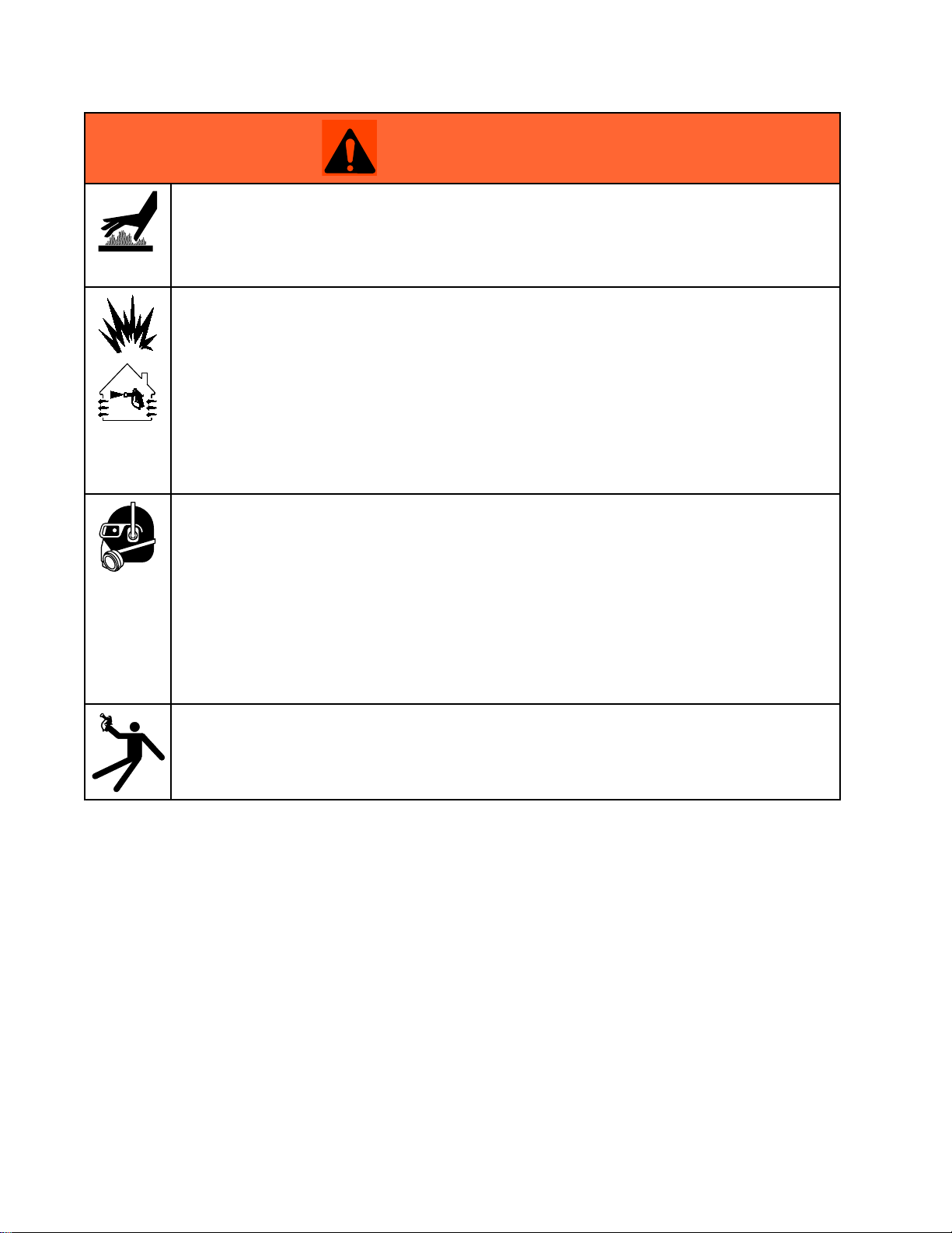
Warnings
WARNING
WARNING WARNING
BURN
BURN BURN
Equipmentsurfacesanduidthatisheatedcanbecomeveryhotduringoperation.Toavoid
severeburns:
•Donottouchhotuidorequipment.
FIRE
FIRE FIRE
Flammablefumes,suchassolvent,inworkareacanigniteorexplode.Tohelppreventre
andexplosion:
•Useequipmentonlyinwellventilatedarea.
•Abrasivematerialexitingblastnozzlecangeneratesparks.Whenammableliquidsareused
•Keepworkareafreeofdebris,includingsolvent,ragsandgasoline.
•Keepaworkingreextinguisherintheworkarea.
PERSONAL
PERSONAL PERSONAL
HAZARD
HAZARD HAZARD
AND
EXPLOSION
AND AND
EXPLOSION EXPLOSION
neartheblastnozzleorforushingorcleaning,keeptheblastnozzleatleast20feet(6
meters)awayfromexplosivevapors.
PROTECTIVE
PROTECTIVE PROTECTIVE
HAZARD
HAZARD HAZARD
EQUIPMENT
EQUIPMENT EQUIPMENT
Wearappropriateprotectiveequipmentwhenintheworkareatohelppreventseriousinjury,
includingeyeinjury,hearingloss,inhalationoftoxicfumes,andburns.Protectiveequipment
includesbutisnotlimitedto:
•Protectiveeyewear
•Protectiveshoes
•Gloves
•Hearingprotection
•Properlyt-testedandgovernmentapprovedrespiratorsuitableforthedustconditions
RECOIL
RECOIL RECOIL
Blastnozzlemayrecoilwhentriggered.Ifyouarenotstandingsecurely,youcouldfalland
beseriouslyinjured.
HAZARD
HAZARD HAZARD
4
334666B
Page 5

Notes
Notes
Notes Notes
334666B 5
Page 6
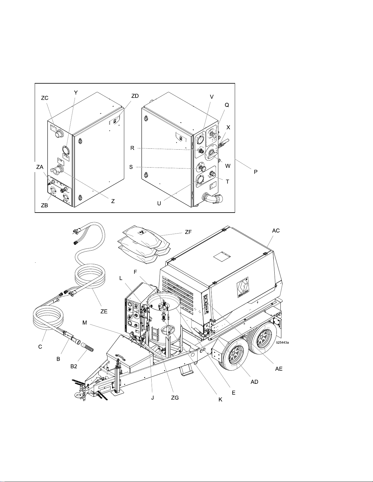
SystemComponentIdentication
System
System System
EQ200T
EQ200T EQ200T
Component
Component Component
and
EQ400T
and and
EQ400T EQ400T
Identication
Identication Identication
6 334666B
Page 7
SystemComponentIdentication
8800000
83000
9
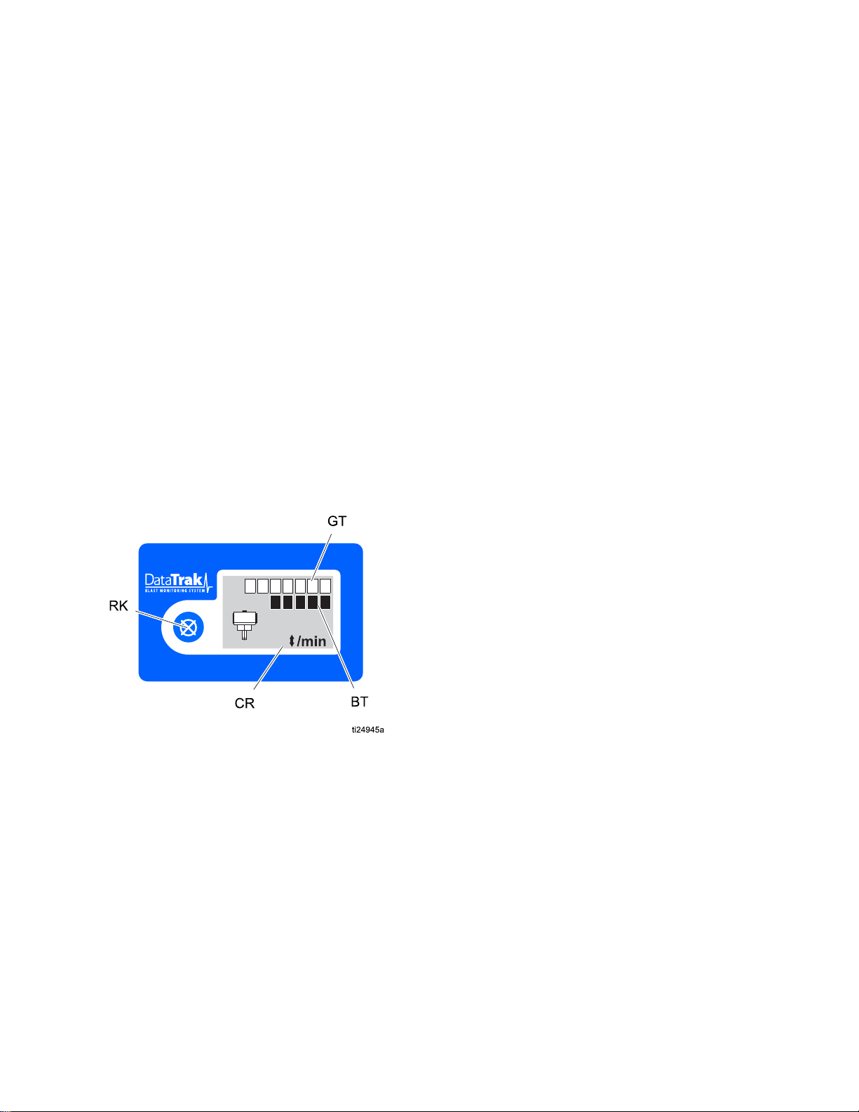
Key:
Key: Key:
B
B2BlastNozzle
C
EPot
FBungPin
JPotDumpValve
KAutoVentValve
L
MAbrasiveBallValve
P
QEmergencyStop
RBlastAirRegulator
S
TPotPressureRegulator
U
DataTrak
DataTrak DataTrak
BlastControlSwitch
BlastHose
BlastCheckValve
ControlBox
AbrasiveMeter
PotPressureGauge
Key:
Key: Key:
V
W
XRinseBallValve
Y
Z
ZA
ZB
ZCSupplyAirPressureGauge
ZD
ZEAccessoryExtensionhose
ZFAbrasiveMaterial
ZGFillPortCheckValve
ACAirCompressor
AD
AE
Controls
Controls Controls
BlastAirPressureGauge
SelectorValve
AirSupplyConnection
BlastConnection
PneumaticControlConnection
ElectricControlConnection
DataTrak(seeDataTrakControls,page7)
AirConnections
AirCompressorControls
Key:
Key: Key:
RK
CRCycle/Rate
BTBatchTotalizer
GTGrandTotalizer
334666B
ResetKey—Resultsinfaults.Pressand
holdforthreesecondstoclearthebatch
totalizer.
7
Page 8
PressureReliefProcedure
Pressure
Pressure Pressure
FollowthePressureReliefProcedure
wheneveryouseethissymbol.
Thisequipmentstayspressurizeduntilpressure
ismanuallyrelieved.Tohelppreventserious
injuryfrompressurizeduid,suchassplashing
uid,followthePressureReliefProcedurewhen
instructed.
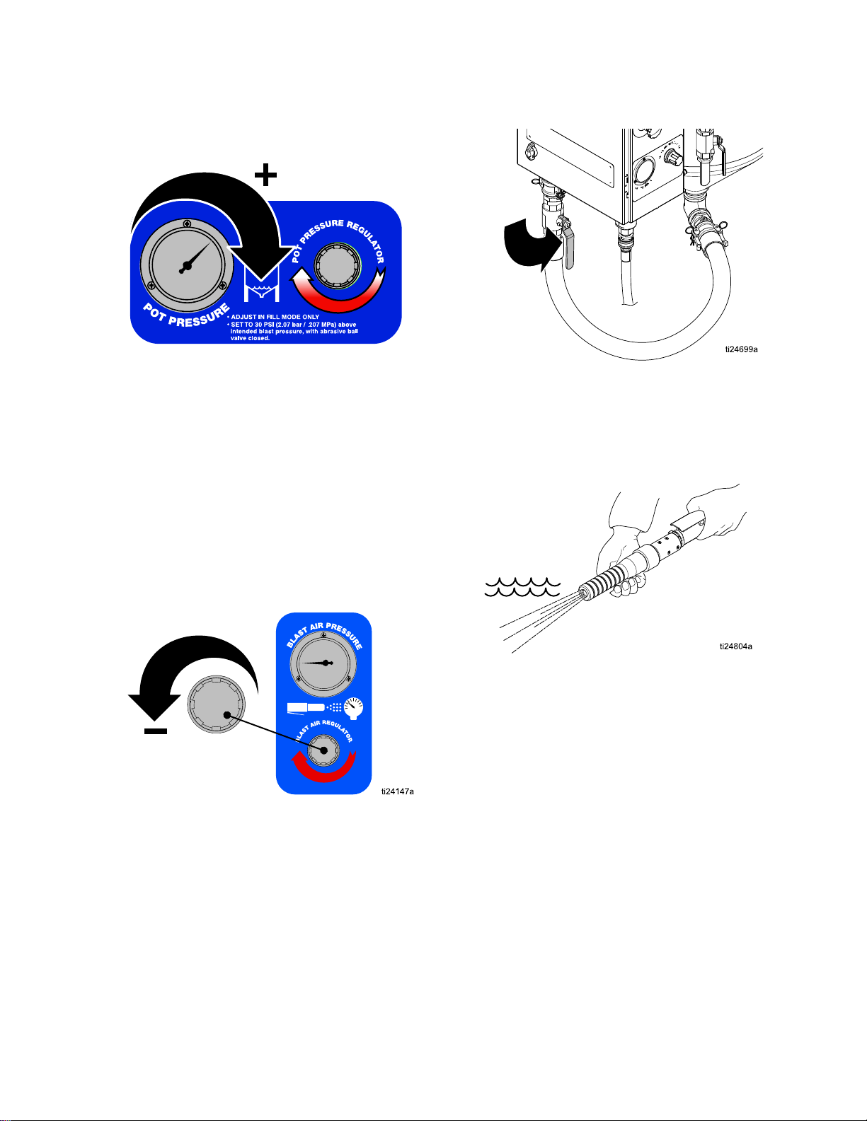
1.Turnthepotpressureregulator(PR)off.
Relief
Relief Relief
Procedure
Procedure Procedure
2.Closetheabrasiveballvalve.
3.Turnthecompressoroffandclosetheinlet
ballvalve.Closethecompressorsupplyair
valve.Engagetheblastcontrolswitchtorelieve
pressureinthesystem.Thendisconnecttheair
inlethosefromthesystem.
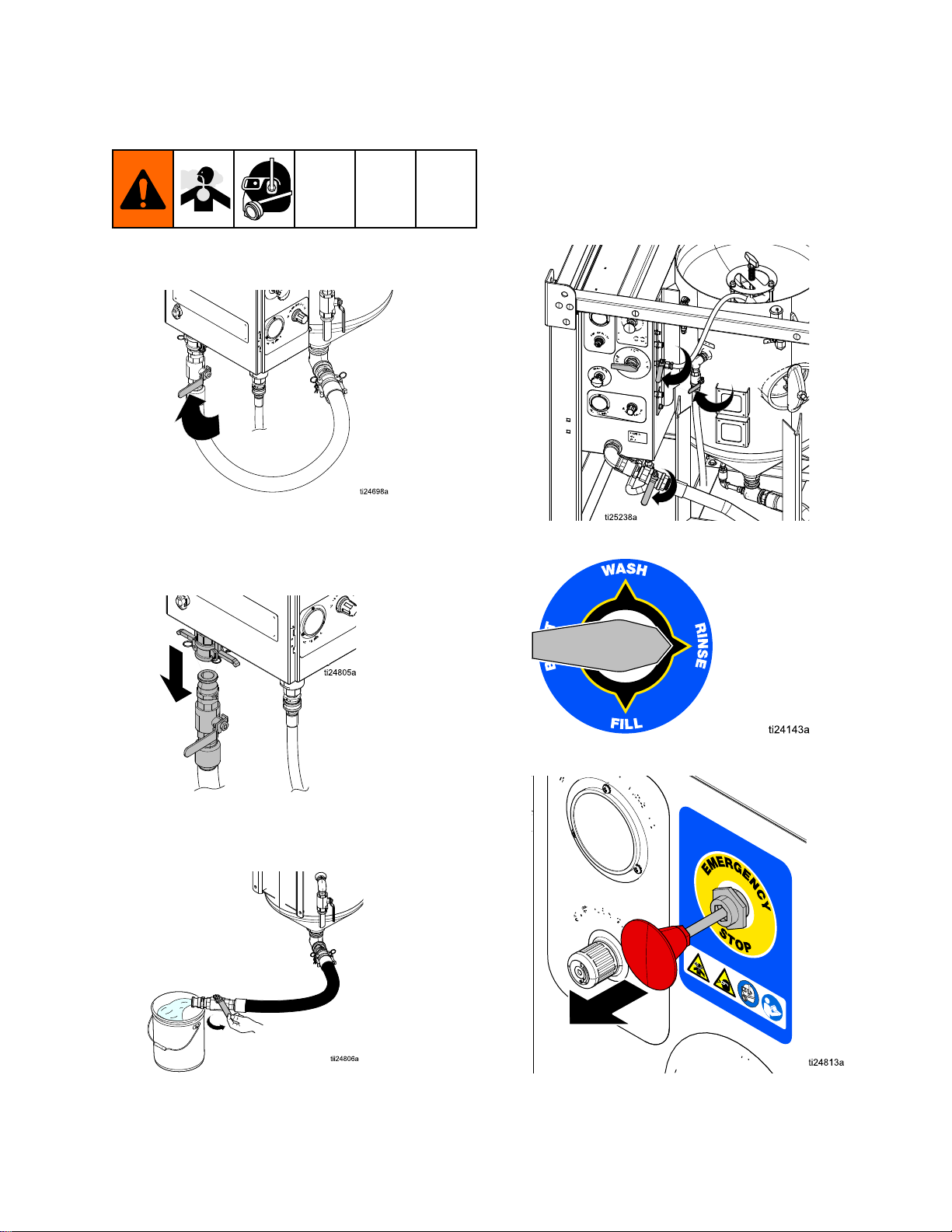
4.Turntheselectorvalve(SL)toFILL.
5.Openthedumpvalve.
6.Verifythatthepotpressuregauge(PG)displays
zeropressure.
8 334666B
Page 9

Operation
Operation
Operation Operation
Checklist
Checklist Checklist
•Checkthecompressedairsupplyaccordingtoits
operatormanual.Makesuretheairbeingsupplied
iscleanandrelativelyfreeofmoistureandoil
topreventwatercontaminationoftheaircontrol
components.
•Makesureairdeliveryvalvesareclosedbeforethe
airsupplycompressorisstarted.
•Makesureallrequiredhoserestraintsandcoupler
pinsareinworkingconditionandproperlyinstalled.
•Makesuretheequipmentissituatedonlevel
ground.Failuretokeeptheunitonlevelground
willmakeitdifcultorimpossibletopurgeallofthe
airfromthepressurevessel.
•Makesuretheequipmentisproperlysupportedon
asurfacethatcanholditstotalweight.Theweight
ofallpersonnel,thematerialbeingblasted,and
anyabrasivebeingstoredmustalsobeconsidered
(seeTechnicalSpecications,page48).
•Makesurethewatertankwillremainfullysupplied
withcleanwatertoavoidanypossibilityofthe
pumprunningdryduringblasting.
Before
Before Before
Starting
Starting Starting
•Makesuretousethecorrecttypeofblastcontrol.
Blastingwith150feet(45m)ormoreofblasthose
requirestheuseofanelectricblastcontrol.An
electricblastcontrolcanalsobeusedonhose
lengthsbelow150feet(45m).
•Makesuretheblasthoseislaidoutasstraightas
possiblebetweentheequipmentandtheworksite
(acoiledblasthosewilluncoilunderpressure).
NOTICE
NOTICE NOTICE
Sharpbendsintheblasthosecouldcausethe
abrasivetowearthroughthehoseandcause
prematurefailureofthehose.
•Makesuretherubbergasketineachhosecoupler
isinworkingcondition.
Lifting
Lifting Lifting
•Lifttheunitwithaliftapparatusratedfor10,000
lb(4535kg)minimum.
•Donotliftthesystembytheliftringontopofthe
compressor.
the
Trailer
the the
Trailer Trailer
Systems
Systems Systems
•Makesurethatthepotiscleanandfreeofany
internaldebris.
•Donotliftthesystembythetie-downringsonthe
trailer.
334666B 9
Page 10
Operation
OFF
START
RUN
ti24706a
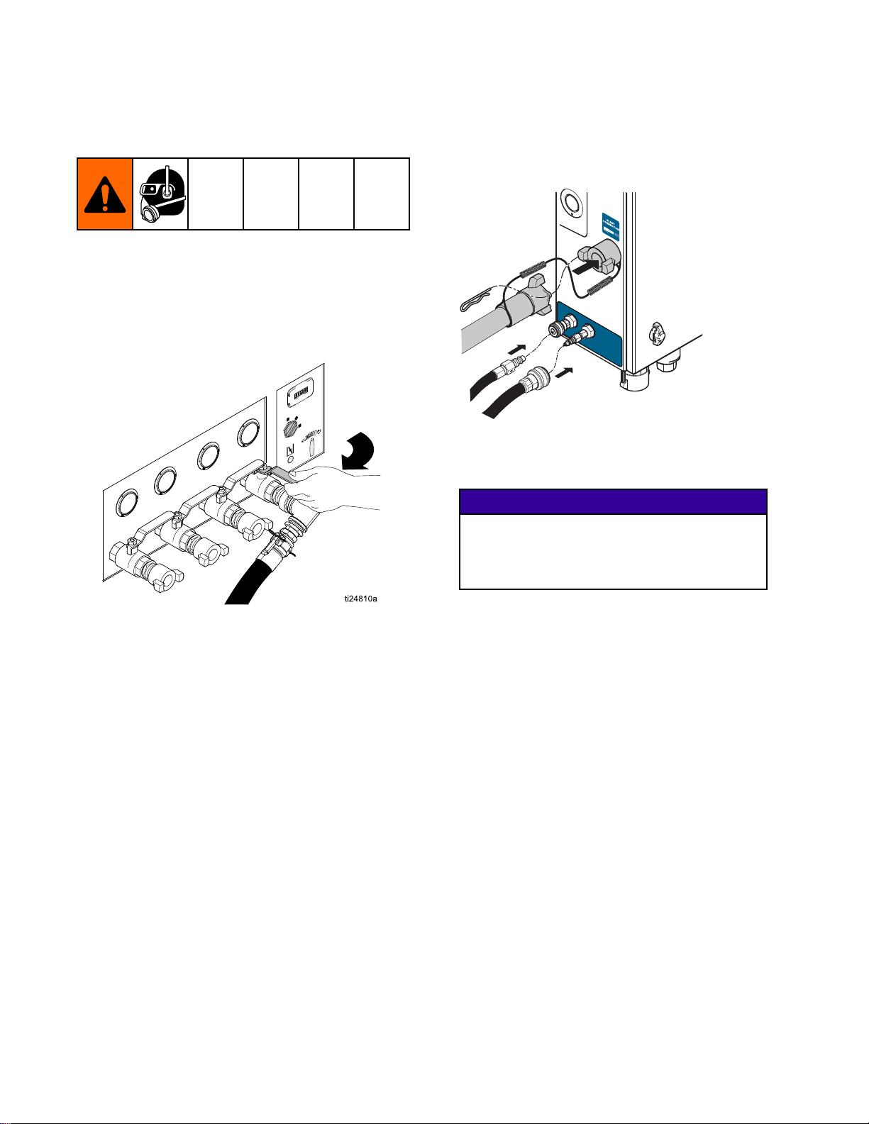
Connecting
Connecting Connecting
Hose
Hose Hose
1.Makesuretheinlethoseconnectionsaretight,
andthathoserestraintsareproperlyinstalled
andsecure.
2.Opentheairsupplyvalve(125psi,8.6Bar,0.86
MPamaximum).Ifnecessary,usearegulatorin
thesupplyairlinetomeetthesespecications.
the
Blast
the the
Blast Blast
Hose
Hose Hose
and
and and
Air
Air Air
NOTE:
NOTE: NOTE:
andstartupinformation.
3.Connecttheblasthose,hoserestraints,control
hoses,andcouplerpins.
NOTE:
NOTE: NOTE:
checkalloftheelectricalconnectionsfromthe
paneltotheblastcontrol.
Seeaircompressormanualforoperation
Ifyouareusinganelectricblastcontrol,
NOTICE
NOTICE NOTICE
Makesurenoelectricalconnectionswill
beexposedtowater.Exposuretowater
couldcauseashortcircuitanddamagethe
equipment.
10 334666B
Page 11
Operation
Setting
Setting Setting
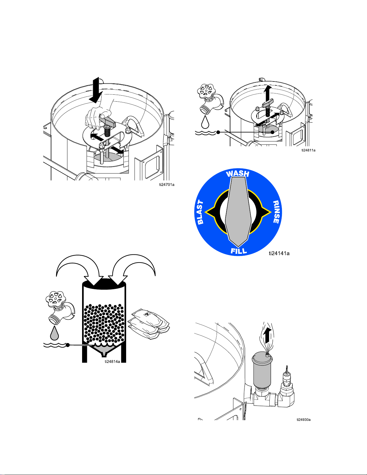
1.Disconnecttheabrasivehoseatthecamand
Up
the
Up Up
groovewiththeabrasiveballvalveclosed.
NOTE:
NOTE: NOTE:
(especiallyunderpressure),releasingthecam
andgroovewiththeballvalveopenwillcausean
unintentionalreleaseofabrasive.
Ifthepotcontainswaterandabrasive
Equipment
the the
Equipment Equipment
4.Disconnectthepumpinlethoseandushthe
watertanktoremoveanyremainingdebris.
Reconnectthepumpinlethose.
5.Fillthewatertankonlywithfreshwater,then
opentheinletballvalve.
6.Closetherinse,dump,andabrasiveballvalves.
7.TurntheselectorvalvetoRINSE.
2.Flushwaterthroughthepotandoutthe
disconnectedabrasiveballvalvebeforellingthe
potwithwaterandabrasive.
3.Reconnecttheabrasivehose.
334666B
8.DisengagetheEmergencyStop.
NOTE:
NOTE: NOTE:
EmergencyStopisdisengaged.
Thewaterpumpwillnotworkunlessthe
11
Page 12
Operation
1
2
10 gal
(30 L)
200-500 lb
(90-227 kg)
9.Alignthebunghandlewiththepinslot,andthen
rmlypushandturnthehandle90°afterthepin
isbelowthebracketslot.Properengagementof
thepinwillholdthebungdownuntilitisreleased.
10.Add10gallons(30liters)offreshwaterto
thepot.Wearappropriatepersonalprotective
equipment,includinganappropriatelyt-tested
governmentapprovedrespiratorsuitableforthe
dustconditions.Addabrasivematerial(minimum
fourbags,maximumten50lb(23kg)bagsof
high-massabrasive,oreight50lb(23kg)bags
oflowmassabrasive).
12.Whenthewaterlevelreachesthebungseal,
rotatethehandletoreleasethebungpin(this
willcausethebungtopopupagainsttheseal
andclosethebung).
13.TurntheselectorvalvetoFILL.
11.Useagardenhoseortherinsehosetowashthe
abrasiveintothepotandclearanyabrasivefrom
thebungandbungseal.
NOTE:
NOTE: NOTE:
not,openthepotpressureregulatorenoughto
causethepumptorunat60cpm.
NOTE:
NOTE: NOTE:
oftheairtrappedinthetopofthepottovent.
Whenairstopsventing,thepotpressuregauge
willstarttoregisterpressure.
Thewaterpumpshouldbegincycling.If
Theautovent/purgevalvewillallowall
12
334666B
Page 13
Operation
ti24824a
14.Waitforpotpressuretoincrease.NOTE: NOTE:
cantakeuptoseveralminutesforthepotto
pressurize.
NOTE:
NOTE: NOTE:
Thebungcannotbepusheddownunless
allofthepressureinthepotisreleasedby
openingthedumpvalve.
15.Setthepotpressure30psi(2.0Bar,0.2MPa)
higherthantheintendedblastpressure.Quickly
openandclosethedumpvalveafterthepump
stalls.Relievepotpressureto40psi(2.7Bar,
0.27MPa)beforeclosingthedumpvalve.
Repeatuntilpotpressureisconsistent.
NOTE:
It
19.Opentheabrasiveballvalve.
NOTE:
NOTE: NOTE:
Makesurethepotpressurereturnstothe
initialsetting(itwillnotreturntotheinitialsetting
ifthemeteringvalveisclosed).
20.Engagetheblastcontrolswitchandbegin
blasting.
16.TurntheselectorvalvetoWASH.
17.Settheblastairpressure30psi(2.0Bar,0.2
MPa)lowerthanthepotpressurewhileblasting.
NOTE:
NOTE: NOTE:
Inordertoadjusttheblastpressure,the
blastcontrolmustbeengaged.Fortheinitial
setting,leavetheabrasiveballvalveclosed.
NOTE:
NOTE: NOTE:
Engageandreleasetheblastcontrol
handleeachtimetheblastregulatorisadjusted.
18.TurntheselectorvalvetoBLAST.
NOTE:
NOTE: NOTE:
Youmayhavetowait1–2minutesforthe
abrasivematerialtoreachthenozzle.
NOTE:
NOTE: NOTE:
Potpressureandblastpressureshould
equalizeduringblasting.Onlysetpotpressure
withtheabrasiveballvalveclosed.Neveradjust
potpressurewhileblasting.
334666B 13
Page 14
Operation
8800000
83000
9
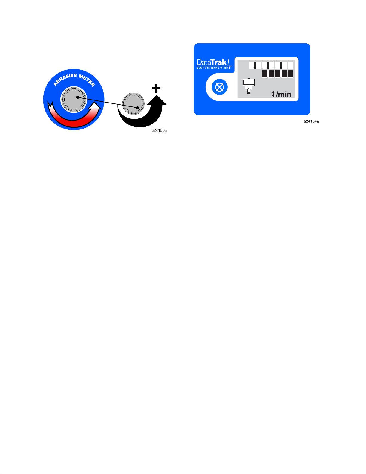
21.Slowlyadjusttheabrasivemetervalvewhilethe
abrasiveisblastingfromthenozzle.Typical
adjustmentrangesfrom1/8to1/4turnopen.
NOTE:
NOTE: NOTE:
settingthepumpcyclerate.Optimalabrasive
mediaconsumptiontypicallyoccurswiththe
cycleratesetat7–10cyclesperminute.
TheDataTrakcanbeusedtoassistin
NOTE:
NOTE: NOTE:
whatyouwillbeblasting.
NOTE:
NOTE: NOTE:
thenincreasetheblastforceasnecessaryto
cleanwithoutdoinganydamagetothesubstrate.
Whenproperlyset,thepumpshouldcycle7-10
timesperminute.Highproductionrateusers
mayneedtoincreasecyclerateabove10cycles
perminute.
Useapieceoftestmaterialsimilarto
Alwaysstartasgentlyaspossibleand
NOTE:
NOTE: NOTE:
youstopblastingformorethan2-3minutes.
Thiswillhelptoextendtheservicelifeofthe
diaphragmvalve.
Closetheabrasiveballvalvewhenever
14
334666B
Page 15
Operation
Blasting
Blasting Blasting
Whenrstlearningtheeffectsoftheblaster,geta
betterunderstandingoftheresultsbystartingata
shallowangle(closerto0°thanto90°)andkeep
thenozzleapproximately16in.(40cm)fromthe
application.Observetheresults,thenreducethe
distance,steepentheangle,andadjusttheblast
regulator.
Astheblastpressureisincreased,slowlyadjust
themeteringvalveandwatchtheDataTrakto
achieve7-10pumpcyclesperminute.See
DataTrakControls,page7.
NOTE:
NOTE: NOTE:
(i.e.80-grit),themoreaggressivetheresults.
Tips
Tips Tips
Theheavierandsmallertheabrasiveparticle
Blasting
Blasting Blasting
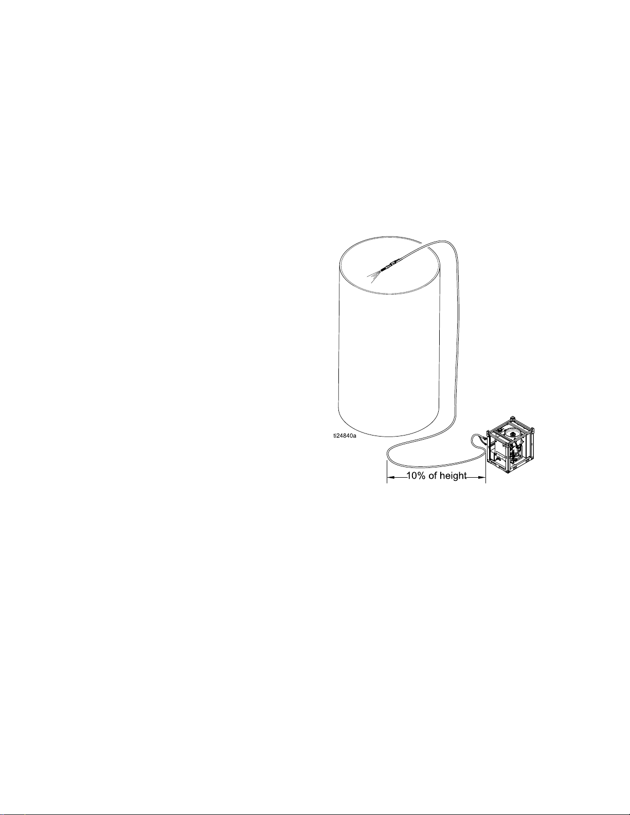
Whenblastingonasurfacehigherthanthe
equipment,makesurethatthereisalengthofblast
hoseonthegroundequalto10-20%oftheheight.
Thehoseonthegroundpreventsunspentabrasive
inthehosefromback-llingtheinternalplumbingof
thepanel.
Forexample:Whenblasting50feet(15m)straight
up,useatleast10feet(3m)ofblasthoseonthe
groundbeforetheblasthosegoesuptotheblasting
height.
on
Higher
on on
Higher Higher
Surfaces
Surfaces Surfaces
334666B 15
Page 16

Operation
Metering
Metering Metering
Thereisnoxedformulaforwhatworksbestineachapplication.Theinformationbelowworksbestforthe
majorityofthetime.Fromthisinitialsetting,adjustmentscanbemadeupordowntogetthefastestremoval
rateswithoutdamagetothesurface.
Normalsettingsare:110psi(7.5Bar,0.75MPa)initialpotsetting,lessthan1/2turnopenmeteringvalve,
blastingpressureat80psi(5.5Bar,0.55MPa).Forapplicationsrequiringhigherperformance,use
high-performanceabrasive(theheaviestmass@80grit)suchasGarnet,andthehighestpressuresthe
compressorcansupport.Theinitialpotpressureshouldalwaysbe30psi(2.0Bar,0.2MPa)abovethe
intendedblastpressure.
Graduallymakeadjustmentstomeetthespecicrequirementsforeachapplication.Higherblastpressures
willrequireturningtheabrasivemeteringvalveslightlymoreopen(andviceversa).Maketheadjustments
(seeDataTrakControls,page7)toachieve7-10cyclesperminutetobethemostefcient(cutatthefastest
ratewhileusingtheleastamountofabrasive).Blastingpressurescanrangebetween30-120psimax
(2.0Bar,0.2MPa–8.2Bar,0.82MPa).
Unlikeconventionalsandblasting,higherpressuresdonotnecessarilymeanbettercleaning.Nozzledistance
andtheangletothesurfacehasaneffectonperformance,asdoestheblastpressure.Choiceofabrasive
alsohasagreateffect.High-performanceabrasiveproducesthebestperformanceandcansaveenough
timetomakeupthedifferenceincost.
NOTE:
NOTE: NOTE:
General
General General
Wood
Wood Wood
Steel
Steel Steel
Fiberglass
Fiberglass Fiberglass
Valve
Valve Valve
Blastingwith150+feetofblasthoserequirestheuseofanelectricblastcontrol.
Settings
Settings Settings
Grit
Grit Grit
40/70
80(usingalow
massabrasive
likeglass)
80-100(using
ahigh-mass
abrasivelike
Garnet)
40-70lowmass
Blast
Size
Size Size
60-80psi(4.1Bar,
0.41MPa-5.5Bar,
0.55MPa)
40-50psi(2.7Bar,
0.27MPa-3.4Bar,
0.34MPa)
100-120psi(6.8Bar,
0.68MPa-8.2Bar,
0.82MPa)
45-65psi(3.1Bar,
0.31MPa-4.4Bar,
0.44MPa)
Pressure
Blast Blast
Pressure Pressure
Abrasive
Abrasive Abrasive
1/4to1/2turns
1/8to1/4turns
1/4–1/2turns
1/8to1/4turns
Dose
Dose Dose
35°-65°
15°-30°
65°-85˚
35°-45˚
Blast
Angle
Blast Blast
Angle Angle
Whentheblast
pressureis
increased,the
abrasivedoseturns
willalsoneedtobe
increased.
Donotwash,asit
mayraisethewood
grain.Brushoff
excessabrasiveafter
thewooddries.
Whentheblast
pressureis
increased,the
abrasivedoseturns
willalsoneedtobe
increased.
Whentheblast
pressureis
increased,the
abrasivedoseturns
willalsoneedtobe
increased.
Notes
Notes Notes
16 334666B
Page 17

Operation
Using
Using Using
Thewashfeaturecausesair-drivenwater(without
abrasive)toblastandrinseareasthathavealready
beenblastedwithabrasive.Itisalsoaconvenient
featureforushingabrasivefromtheblasthose.
Therewillalwaysbesomeresidualabrasivein
theblasthose.Neverusethewashfeatureon
anysurfaceotherthanwhereyouhaveblasted,or
intendtoblast.Itwillaffect/dullthesurface.
Donotusethewashfeatureonwoodthathas
beenblasted.Itcoulddamagethewoodandcause
thegraintorise.Waitforthewoodtodryandthen
useabroom,brush,orvacuumtoremoveany
residualabrasive.
1.Closetheabrasiveballvalve.
the
Wash
the the
Wash Wash
Feature
Feature Feature
NOTICE
NOTICE NOTICE
NOTICE
NOTICE NOTICE
2.TurntheselectorvalvetoWASH.
3.Blast1–2minutesuntiltheabrasiveiscleared
fromthehose.
4.Theequipmentisnowreadytowashany
previouslyblastedsurfaces.
334666B
17
Page 18

Operation
Relling
Relling Relling
1.Closetheabrasiveballvalve.
2.TurntheselectorvalvetoRINSE.
3.Openthedumpvalveslowlytorelievethewater
pressureinthepot.
the
Pot
with
the the
Pot Pot
Abrasive
with with
Abrasive Abrasive
4.Afterallofthepressureinthepothasbeen
relieved,engagethebungpinbycompressing
thespringandturningthehandle90°toholdthe
bungintheopenposition.
5.Addtheabrasive(minimumfourbags,maximum
ten50lb(23kg)bagsofhigh-massabrasive
oreight50lb(23kg)bagsoflow-mass
abrasive)andcontinuetheproceduresfrom
SettingUptheEquipment,page11.
NOTE:
NOTE: NOTE:
willbedrainedfromthepot.Alldisposalsmust
complywithnational,state,andlocalregulations.
Bepreparedtocapturethewaterthat
NOTE:
NOTE: NOTE:
thepottoallowadditionalabrasivetobeadded.
Morewatermayneedtobedrainedfrom
18 334666B
Page 19

Operation
Shutting
Shutting Shutting
1.Whenyouhavenishedblasting,performwash
untilalloftheabrasiveisushedfromtheblast
hose.SeeUsingtheWashFeature,page17.
2.TurntheselectorvalvetoRINSE,andwiththe
abrasiveballvalveclosed,continuetoblastuntil
waterisclearedfromthehose.Thisistodrythe
insideofthehoseforstorage.
Down
Down Down
5.Holdabucketunderthecam-lockcoupler,then
turntheselectorvalvetoWASH.Thiswillclean
debrisfromthecam-lockcouplerandgasket.
NOTE:
NOTE: NOTE:
procedure.
NOTE:
NOTE: NOTE:
thatwillbewashedoutofthepanelplumbingand
outofthegroovetting.
6.TurntheselectorvalvetoFILL.Thiswillhelp
pushtheabrasiveoutthroughtheabrasivehose.
7.Placeabucketundertheabrasivehose.Slowly
openandclosetheabrasiveballvalvetoush
abrasivematerialfromthepot.Repeatseveral
times.Oncenoabrasivematerialowsfromthe
hose,closetheabrasiveballvalve.
Makesurethegasketisinplaceafterthe
Besuretocatchtheunspentabrasive
3.Opentheabrasiveballvalve,thenopenthedump
valveuntilthepotpressuregaugereads0psi.
Closetheabrasiveballvalveanddumpvalve.
NOTE:
NOTE: NOTE:
Iftheuntilwillbeshutdownformorethan24
hours,proceedtothenextstep.
4.Disconnecttheabrasiveballvalvecam-lockby
removingthecouplerpinsandpullingtherings
outanduptopullthetwocamsawayfromthe
groove.
Short-termshutdownisnowcomplete.
NOTE:
NOTE: NOTE:
neededforeachbagofabrasivestillinthepot.
Coverthebucketsduringstoragesodebrisdoes
notcontaminatetheabrasive.
Estimatethata5gallonpailwillbe
334666B 19
Page 20

Operation
8.Engagethebungpintoholdthebungopenand
allowairtoenter.
9.Opentheabrasiveballvalveandushthepotof
anyremainingabrasivematerial.
10.Closethepotbungandconnectthe
abrasivehose.Relievepressure
tocompletesystemshutdown(see
PressureReliefProcedure,page8).
NOTE:
NOTE: NOTE:
beexposedtotemperaturesbelowfreezing.See
WinterizingtheEquipment,page21.
Thesystemmustbewinterizedifitwill
20 334666B
Page 21

Operation
Winterizing
Winterizing Winterizing
Vapor-AbrasiveBlastersmustbewinterized
wheneverthereisapossibilityoffreezing
temperaturesduringstorage.Itisimperativethat
youanticipatethepossibilityofafreezeandalways
protecttheunitduringfallandwinterseasons,evenif
beingstoredonlyovernight.
1.Makesureallofthewaterhasbeendrained
fromthepot.Reconnecttheabrasivehoseafter
drainingthepot.
2.Makesurethepotbungisintheclosedposition.
Thiswillpreventdebrisfromenteringthepot
duringstorage.
3.Drainthewatertankbydisconnectingthepump
inlethoseandopeningtheinletballvalve.
the
Equipment
the the
Equipment Equipment
5.TurntheselectorvalvetoRINSEandopenthe
rinseball-valve.Whileholdingtherinsehose
overthepot,runthepumpuntilwindshieldwash
comesoutoftherinsehose.
6.Movetheselectorvalveintotheotherthree
positions(WASH,BLAST,andFILL).Conrm
thattheinternalwatertubingllswithwindshield
washbeforeturningtheselectorvalvetothenext
position.
NOTE:
NOTE: NOTE:
windshieldwashforfullprotection.
7.EngagetheE-Stop.
8.Reconnectthepumpinlethosetotheinletball
valve.
9.Add1–2gallons(4–8liters)ofwindshieldwash
tothewatertank.Makesurethattherinse
ball-valveandthedrainball-valveareleftopen.
All3/8in.tubingshouldbelledwith
NOTE:
NOTE: NOTE:
state,andlocalregulations.Inaddition,ifthe
watercontainsarustinhibitor,youmaywantto
retainandpreservethewaterduetotheexpense
oftheinhibitor.
4.Drainthepumpinlethose,theninserttheend
intoawindshieldwashcontainer.Choosea
windshieldwashwitharatingthatwillprotectthe
equipmentforthelowesttemperaturesinyour
area.
Alldisposalsmustcomplywithnational,
NOTICE
NOTICE NOTICE
Wheniceformsbehindtheseals,thesealscan
becomedamaged.Duringstorage,positionall
ball-valvesintheopenposition.
334666B
21
Page 22

Troubleshooting
Troubleshooting
Troubleshooting Troubleshooting
Thepotwillnotproperly
pressurize.
Problem
Problem Problem
Theairsupplyisinadequate.Makesuretheairinletpressuregauge
TheEmergencyStopisengaged.DisengagetheEmergencyStop.
Inadequatewatersupplytothe
pump.
Thepotpressureregulatorisset
toolow.
Thepotbungcannotsealproperly.
TheAuto-Ventvalvewillnotseal.
Thepotpressurereliefvalveis
dischargingwater.
Cause
Cause Cause
reads100-125psi.Ifthegaugedoes
notread100–125psi,checktheair
compressorforpropersetup.
Makesurethewatertankisfullandthe
inletballvalveisopen.
Increasethesettingonpotpressure
regulator.
Cleanallabrasivefromthebungand
seal.Makesurethebungspringislifting
andthebungisrmlyagainsttheseal.If
cleaningdoesnotsolveissue,replace
bungseal.
SeeCleaningtheAuto-VentValve,page
31.
Decreasethepotpressureto145psi
(10.3bar,1.03MPa)orless.Ifthevalve
weepsorrelievesat145psi,replace
valve(Kit17D785).
Solution
Solution Solution
Theblastpressurewillnot
reachthedesiredsetpoint.
22
Thepotorpumpisleaking
pressure.
Thepotpressureregulatoris
malfunctioning.
Theairsupplyisinadequate.Makesuretheairinletpressuregauge
Themainairregulatoris
malfunctioning.
Theblastairregulatoris
malfunctioning.
Makesuretheabrasiveballvalveandthe
dumpvalveareclosed.Ifpotpressure
gaugestillcreepsdownward.See
CheckingforLeaks,page26.
Replacethepotpressureregulator
assembly(17C132).
reads100-125psi.Ifthegaugedoes
notread100–125psi,checktheair
compressorforpropersetup.
SeeRepairingtheMainAirRegulator,
page28(EQ600–Kit17C131,EQ300
–Kit17C129).
Replacetheblastairregulator(Kit
17C625).
334666B
Page 23

Troubleshooting
Problem
Problem Problem
Noabrasiveowsfromthe
nozzleduringblastmode.
Cause
Cause Cause
Thepotdoesnothaveasufcient
amountofabrasive.
Thesystemisnotproperlysetup.
Thereisanobstructioninthe
mediacircuit.
Thediaphragmvalveisnot
working.
Thereisblockageinsidethepotor
insidetheabrasivehosebetween
thepotandthepanel.
Solution
Solution Solution
SeeRellingthePotwithAbrasive,page
18.
SeeSettingUptheEquipment,page11.
Makesurethepotpressureisproperly
set.Thepotpressuremustbeset30
psiabovetheblastpressure.Makesure
theselectorvalveissettoBLAST.The
abrasiveballvalvemustbeopen.The
abrasivemeteringvalvemustbeatleast
1/8turnopen.
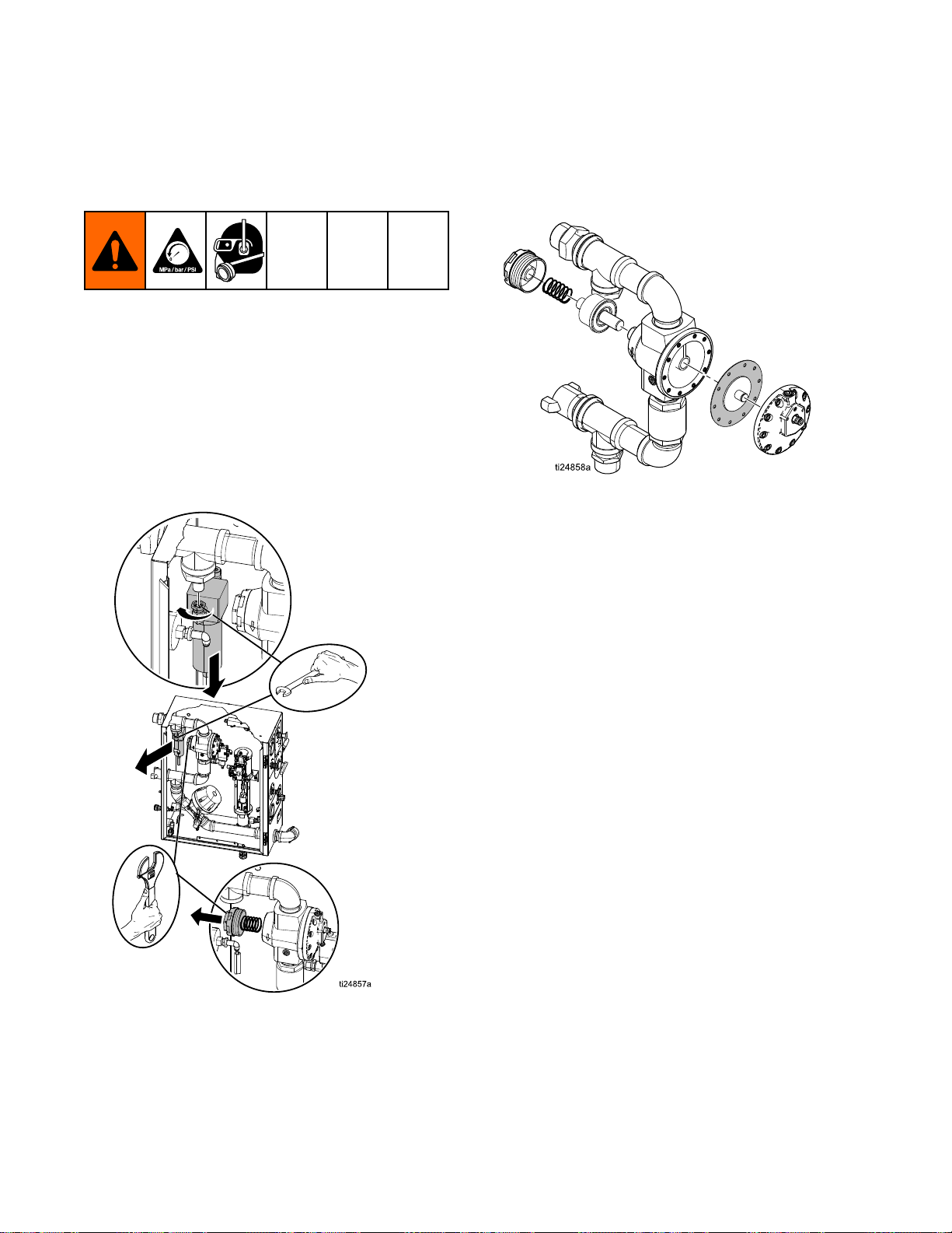
SeeFlushingtheDiaphragmValve,page
29.
SeeRepairingtheDiaphragmValve,
page30.
Makesuretheballvalveisclosed,then
disconnectthecam-lockcoupler.Open
theabrasiveballvalveslightlyandmake
sureabrasiveisowingformtheabrasive
hose.Ifnot,followtheshutdown
procedure(seeShuttingDown,page19).
Thoroughlyushthepotandthemedia
hoseafterdrainingmediaandwater.
Noblastairowwhenthe
blastcontrolisengaged.
Thewaterpumpcycles
whiletheblastcontrol
engaged.
Noblastairowwhenthe
blastcontrolisengaged.
Thewaterpumpdoes does
cyclewhiletheblastcontrol
engaged.
does
Theblastregulatorisnotadjusted
tothecorrectpressure.
Thetubingfromthemain
airregulatorisnotproperly
connected.
Theblastairregulatoris
malfunctioning.
Themainairregulatoris
malfunctioning.
Theairsupplyisinadequate.Makesuretheairinletpressuregauge
not
not not
TheEmergencyStopisengaged.DisengagetheEmergencyStop.
Theelectricblastcontrolcircuitis
malfunctioning.
Adjusttheblastregulatortothedesired
pressurewhiletheblastcontrolis
engaged.
Conrmthatthetubingfromtheblast
regulatortothemainairregulatoris
intact.SeeHoseSchematic,page42.
Replacetheblastairregulator(Kit
17C625).
SeeRepairingtheMainAirRegulator,
page28(EQ600–Kit17C131,EQ300
–Kit17C129).
reads100-125psi.Ifthegaugedoes
notread100–125psi,checktheair
compressorforpropersetup.
Inspectthehosecablefordamagedor
shortedwiring.Checkthebatteryand
controlpanelconnections.Makesurethe
DCpowersourceis12V.Checkthe3A
fuseinsidethecontrolpanel,andreplace
itifnecessary.Checkthecurrentowin
thecircuit.Ifcurrentexists,replacethe
relay(EQ5179).
334666B 23
Page 24

Troubleshooting
Problem
Problem Problem
Theblastcontrolisnot
engagedbutblastingstill
occurs.
Theblastspraypatternis
irregular.
Cause
Cause Cause
Thepneumaticblastcontrolcircuit
ismalfunctioning.
Themainairregulatorisstuck
open.
Theblastcontroltubingisnot
connectedproperly.
Electricblastcontrolcircuitis
malfunctioning.
Pneumaticblastcontrolcircuitis
malfunctioning.
Incorrectabrasiveisbeingused.
Thepotdoesnothaveasufcient
amountofabrasive.
Solution
Solution Solution
SeePneumaticBlastControlCircuit,
page27.
SeeRepairingtheMainAirRegulator,
page28(EQ600–Kit17C131,EQ300
–Kit17C129).
Ensureairtubingisroutedandconnected
properly.SeeHoseSchematic,page42.
Inspecthosecablefordamagedor
shortedwiring.Checkbatteryandcontrol
panelconnections.EnsureDCpower
sourceis12V.Check3Afuseinside
controlpanelandreplaceitifnecessary.
Checkcurrentowincircuit,ifcurrent
exists,replacerelay(EQ5179).
SeePneumaticBlastControlCircuit,
page27.
Usethecorrectabrasive.See
MeteringValveSettings,page16.
Rellthepotwithabrasive.See
RellingthePotwithAbrasive,page18.
Thepotpressuresettingis
incorrect.
TheAuto-Ventvalvedoesnotvent
airwhenthepotislled.
Thediaphragmvalveis
malfunctioning.
Thereisblockageinsidethepotor
insidetheabrasivehosebetween
thepotandthepanel.
Performthepressurereliefprocedure
(seePressureReliefProcedure,page8)
andresetpotpressure(see
SettingUptheEquipment,page11).
MakesuretheAuto-Ventvalve
isworking.PerformtheAutoVentcleaningprocedure(see
CleaningtheAuto-VentValve,page31).
Performthediaphragm
ushprocedure(see
FlushingtheDiaphragmValve,page29).
Ifushingdoesnotsolveproblem,see
RepairingtheDiaphragmValve,page30.
Makesuretheballvalveisclosed,then
disconnectthecam-lockcoupler.Open
theabrasiveballvalveslightlyandmake
sureabrasiveisowingformtheabrasive
hose.Ifnot,followtheshutdown
procedure(seeShuttingDown,page19).
Thoroughlyushthepotandthemedia
hoseafterdrainingmediaandwater.
24
334666B
Page 25

Troubleshooting
Problem
Problem Problem
Astronghoserecoiloccurs
frequentlywhentheblast
controlswitchisengaged.
Cause
Cause Cause
Theunitisnotonalevelsurface.Placetheunitonalevelsurface.Ifthis
isimpossible,theAuto-Ventmustbeon
thehighersideoftheunit.
Theinitialpotpressureisnotset
correctly.
TheAuto-Ventismalfunctioning.Performauto-ventclean-
Thediaphragmneedstobe
ushed.
Conrmthattheauto-ventvalveis
workingandsetinitialpotpressure30
psi(2.0bar,0.20MPa)abovetheblast
pressure.
ingprocedure(see
CleaningtheAuto-VentValve,page31).
Performthediaphragm
ushprocedure(see
FlushingtheDiaphragmValve,page29).
Ifushingdoesnotsolvetheproblem,see
RepairingtheDiaphragmValve,page30.
Solution
Solution Solution
334666B 25
Page 26

Troubleshooting
ti24825a
Troubleshooting
Troubleshooting Troubleshooting
Checking
Checking Checking
1.Openthedumpvalve.Checkpotpressure
gauge,thenclosethedumpvalve.
Lookatthepressuregaugetoconrmthatall
pressurehasbeenrelievedfromthepot.
for
Leaks
for for
Leaks Leaks
Examples
Examples Examples
3.Makesurethebungisengagedwithitsseal.
TurntheselectorvalvetoWASH,thenopenthe
abrasiveballvalvetopressurizethepot.Setthe
potpressureto145psi(9.9Bar,0.99MPa).
4.Checkthewaterpumptoconrmthatnowater
isleakingfromtheTSLllport.
NOTE:
NOTE: NOTE:
pressurizes.Ifthepumpdoesnotstall,replace
theseals.Refertothepumpmanualforrepair
information.
5.Checkforanywaterleakingfromeithercheck
valve.Ifacheckvalveisleaking,itmustbe
repairedorreplaced.Ifthevalvesaredamaged,
thepotwillnotbeabletomaintainpressure.
Also,checkthepotpressurereliefvalve.Ifthe
valveisweepingatpotpressuresof145psior
less,itneedstobereplaced.
Thepumpshouldstallafterthepot
2.Disconnectthetubingattheblastcheckvalve(L)
andatthellportcheckvalve(ZG).
6.Closetheabrasiveballvalve,thendisconnect
thequickcouplerandconrmthattheballvalve
isnotleaking.Replacetheabrasiveballvalve
ifitisleaking.
26 334666B
Page 27

Troubleshooting
Pneumatic
Pneumatic Pneumatic
1.AttheAir-Relay,disconnectthepush-to-connect
tubingandcheckthetriggercircuit(fromtheblast
controlhandle).
Blast
Blast Blast
Control
Control Control
Circuit
Circuit Circuit
2.Withtheblastcontrolactivated,conrmthat
thereisairowingfromthedisconnectedtube.
NOTE:
NOTE: NOTE:
pressurebuttheairvolumeisreduceddueto
thesizeofthettingsandtubing.Ifyoudonot
getsupplyairpressure,checktheblastcontrol
handleforproperoperation,andchecktheblast
controlhosestomakesuretheyarenotkinked
orinternallyblocked.
3.Checkthein-linelterattheindustrialinterchange
nippleconnectiononthesideofthepanel(where
youattachtheblastcontrolhose).
4.Ifthepreviousstepsdonotxtheissue,replace
theairrelay(KitEQ5179).
Theairowshouldbeatsupplyair
334666B
27
Page 28
Repair
Repair
Repair Repair
Repairing
Repairing Repairing
NOTE:
NOTE: NOTE:
(EQ600)orKit17C129(EQ300).
1.PerformPressureReliefProcedure,page8.
2.Makesurealloftheairpressureisrelievedin
3.Useacrescentwrenchthatcanopento2in.(5
RepairpartsareavailableinKit17C131
theunit.Removethewaterseparatorlterfor
accesstothepistoncoverandreturnspring.
cm)tounscrewthepistoncover.
NOTE:
NOTE: NOTE:
the
Main
the the
Main Main
Thereisaspringinsidethiscover.
Air
Air Air
Regulator
Regulator Regulator
4.Unscrewthediaphragmcoverforaccesstothe
diaphragmandtotheendofthepistonshaft.
5.Removethediaphragmandinspectforany
cracksortears.Replacethediaphragmif
necessary.
6.Carefullyremovethespringandpistonassembly,
thencleanoutanydebrisinthebodyofthe
regulator.
7.Pushthepistonshaftandremovethepistonfrom
theoppositeendoftheregulatorhousing.
8.Inspectthepistonforanyforeignmatterthatmay
havebeenthecauseforthepistontostayopen.
9.Inspectforanydamagetothepistonshaftwhere
itinteractswiththediaphragmcup.
NOTE:
NOTE: NOTE:
maincheckvalveisnotsealing.Contactyour
distributorifthishappens.
Excessivewearhereindicatesthe
28 334666B
Page 29

Repair
Flushing
Flushing Flushing
Thisprocedurecanbeperformedwiththecomponent
stillmountedinthepanel.
Iflarge-gritabrasiveorotherforeignmatterbecome
lodgedinthediaphragmvalve,itwillbecome
necessarytoushthevalve.Thisisasimple
procedure;however,itdoescausethereleaseofa
largevolumeofairtoescapethroughthereleased
quickcoupling.Youneedtobepreparedforthe
releaseofairbypullingthequickcouplergrommet
outofitsgroovesothatitdoesnotgetlost.
1.OperatetheunitinWASH(see
UsingtheWashFeature,page17)until
allabrasiveclearsfromtheblasthose.
the
Diaphragm
the the
Diaphragm Diaphragm
Valve
Valve Valve
3.Disconnectthequickcouplingattheabrasive
ballvalve(notatthebottomofthepot).
4.TurntheselectorvalvetoWASH.Thiswillpump
wateroutofthequickcouplerandallowyou
toreachupinsideandclearallabrasiveand
removethegrommet.
5.Makesurenothingisinthepathoftheopen
quickcoupler,thenengagetheblastcontrol
brieyandseveraltimes.
NOTE:
NOTE: NOTE:
cam-lockcoupling.Ifthisdoesnotoccur,the
diaphragmvalveismalfunctioning.Replace
entirediaphragmcanister(EQ5140–EQ600,
EQ5142–EQ300).
Highowairshouldescapethroughthe
2.Closetheabrasiveballvalve,thenturnthe
selectorvalvetoRINSE.
6.Holdthemaleendofthequickcouplerupto
thewatercomingfromthecam-lockendofthe
coupler.Cleanoffanydirtorabrasive.
7.TurntheselectorvalvetoRINSEtostoptheow
ofwater.
8.Re-insertthegrommetintoitsinternalgroove
insidethecam-lock.
9.Reconnectthequickcoupler.Ifproperlycleaned
andconnected,thereshouldbenoleaksatthe
couplerduringoperation.
334666B 29
Page 30

Repair
1
2
3
4
Repairing
Repairing Repairing
NOTE:
NOTE: NOTE:
–EQ600)canbereplacedwithoutremovingthe
assemblyfromthepanel.Youwillneedan8mm
AllenwrenchfortheEQ600Sanda6mmforthe
EQ300S.
1.PerformthePressureReliefProcedure,page8.
Thediaphragm(17C127–EQ300,17C128
the
Diaphragm
the the
Diaphragm Diaphragm
Valve
Valve Valve
3.Replacethediaphragm(naturalrubber
compound)andhand-tightenitasfaraspossible
toestablishthealignmentwiththecanister.
NOTE:
NOTE: NOTE:
diaphragmandtheactuator.Keeptheshims
andreusethem(theydonotcomewith
thereplacementdiaphragm).Donotcause
anypre-loadortorqueonthediaphragmby
over-tighteningitinamisalignedposition.
4.Insertall4Allen-headcapboltsbutdonottighten
them.
5.Applymorethan80psi(5.5Bar,MPa)air
pressuretotheregulatorinlettocausethepiston
toretract.
6.Withthepistonretracted,hand-tightenthe4
Allen-headcapbolts.
7.Releasetheairpressure.
8.Tightenthecap-boltsinanalternatingpattern
(seeimagebelow)to80+/-8in-lb(9+/-0.9N•m).
Thiswillcauseaslightbulgeinthediaphragm
betweenthecanisterandthestainlesssteel
casting.
Therearetwoshimsbetweenthe
2.Loosenall4Allen-headcap-boltsevenlyand
thenremovethemcompletelywhilesupporting
thecanisterofthediaphragmvalve.
9.Testandconrmthattheunitisworkingproperly.
NOTE:
NOTE: NOTE:
chargetheequipment–thereisnoneedtouse
abrasiveforthistest.
Thiscanbedoneusingonlywaterto
30 334666B
Page 31

Repair
Cleaning
Cleaning Cleaning
Afterthepop-uphasbeenclosedwhilellingthepot,
theauto-ventvalveshouldreleaseair(youshouldbe
abletoheartheairventing).
Thepotpressuregaugewillnotshowpressureuntil
theauto-ventvalvehasbledalloftheairandsealed.
Iftheauto-ventvalvedoesnotreleaseair,orifwater
leaksfromthestemduringthellprocess,thestem
valvemaybecloggedorfaulty.
Performthefollowingproceduretocleanaclogged
auto-ventvalve.
1.Trytopushandquicklyreleasethevalvewith
yournger.Ifthatdoesnotcausethevalveto
seal,openthedumpvalvetoreleaseallofthe
pressureinthepot.
2.TurntheselectorvalvetoRINSE.
the
Auto
the the
Auto Auto
Vent
- --Vent Vent
Valve
Valve Valve
3.Usetherinsehosetoforcewaterbackwardsinto
thevalvestem.
NOTE:
NOTE: NOTE:
theissue,replacethewholevalveassembly
(EQ1860).
Thevalvestemitselfisinternallyattachedtothe
oatanditisnoteld-serviceable.Donottryto
removethevalvestem.Damagetotheequipment
willoccur.
Ifthepreviousstepsfailtoresolve
NOTICE
NOTICE NOTICE
334666B 31
Page 32
Repair
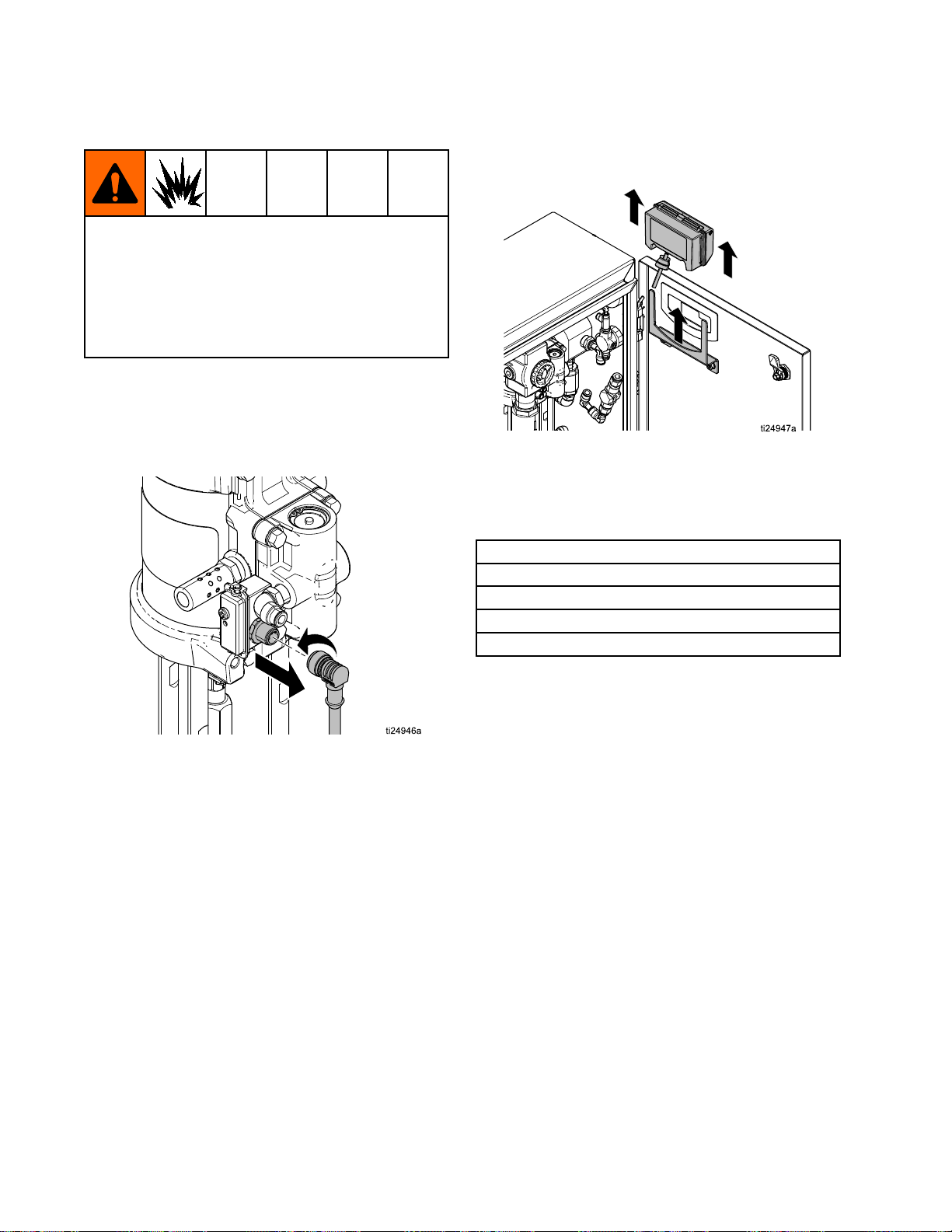
Replacing
Replacing Replacing
FIRE
AND
FIRE FIRE
AND AND
Toreducetheriskofreandexplosion,thebattery
mustbereplacedinanon-hazardouslocation.
Useonlyanapprovedreplacementbattery(see
table).Useofanunapprovedbatterywillvoid
Graco’swarranty.
Replace
Replace Replace
1.Unscrewcablefromthebackofthereedswitch
assembly.
2.Removethecablefromthetwocableclips.
the
DataTrak
the the
DataTrak DataTrak
EXPLOSION
EXPLOSION EXPLOSION
Battery
Battery Battery
HAZARD
HAZARD HAZARD
Battery
Battery Battery
3.RemovetheDataTrakmodulefromthebracket.
Takethemoduleandattachedcabletoa
non-hazardouslocation.
4.Removethetwoscrewsonthebackofthe
moduletoaccessthebattery.
5.Disconnecttheusedbatteryandreplaceitwith
anapprovedbattery.
Energizeralkaline#522
Vartaalkaline#4922
Ultralifelithium#U9VL
Duracellalkaline#MN1604
Approved
Approved Approved
Batteries
Batteries Batteries
32 334666B
Page 33

Repair
Replacing
Replacing Replacing
FIRE
AND
FIRE FIRE
AND AND
Toreducetheriskofreandexplosion,thefuse
mustbereplacedinanon-hazardouslocation.
Useonlyanapprovedreplacementfuse(see
table).UseofanunapprovedfusewillvoidGraco’s
warranty.
Replace
Replace Replace
1.Removethescrew,metalstrap,andplastic
holder.
2.Pullthefuseawayfromtheboard
3.Replacewithanapprovedfuse.
the
DataTrak
the the
DataTrak DataTrak
EXPLOSION
EXPLOSION EXPLOSION
Fuse
Fuse Fuse
HAZARD
HAZARD HAZARD
Fuse
Fuse Fuse
DataTrak
DataTrak DataTrak
Number
Number Number
289822
Allotherpart
numbers
Approved
Approved Approved
Part
Part Part
*Series
*Series *Series
Fuses
Fuses Fuses
Letter
Letter Letter
AorB
Candlater
A
Bandlater24V216
Fuse
Required
Fuse Fuse
Required Required
24C580
24V216
24C580
334666B 33
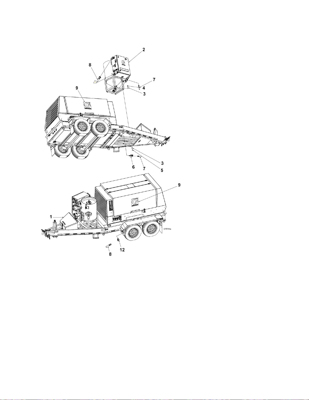
Page 34

Parts
EQ200T
Parts
Parts Parts
EQ200T
EQ200T EQ200T
and
EQ400T
and and
EQ400T EQ400T
EQ200T EQ200T
and
EQ400T
and and
EQ400T EQ400T
Parts
Parts Parts
List
List List
Ref.
Ref. Ref.
34 334666B
Part
Part Part
1
2
Description
Description Description
PRESSUREPOT,6.5
cf,assy
ENCLOSURE,blast
Qty.
Qty. Qty.
1
1
Ref.
Ref. Ref.
Part
Part Part
Description
Description Description
EQ200TModels
EQ400TModels
Qty.
Qty. Qty.
Page 35

Parts
Ref.
Ref. Ref.
Part
Part Part
4LABEL,branding1
5
17D786KIT,replacement,hose
17D787KIT,replacement,
7
EQ5149EQ200TModels
EQ5135EQ400TModels
9
EQ5183CABLE,cord,electric,
10
EQ1943EQ200TModels
Description
Description Description
restraint
couplerpin
VALVE,abrasive,
media
blastcontrol
HOSE,abrasivemedia
Qty.
Qty. Qty.
1
1
1
1
Ref.
Ref. Ref.
Part
Part Part
EQ5208EQ400TModels
12ADAPTER,cam
EQ1934EQ200TModels
EQ1046EQ400TModels
14206994
16
EQ1881HOSE,tubing,natural,
17111743
18
EQ1273HOSE,tubing,natural,
19
EQ1151
22
EQ1519BOLT,hexhead,ss,
Description
Description Description
groove,typeF,ss
FLUID,TSL,8oz.
bottle
1/4in.
WASHER,at
3/8in.
NUT,nylok,ss,3/8–164
1/2-13x1–1
Qty.
Qty. Qty.
1
1
2
4
4
4
334666B 35
Page 36

Parts
12
Enclosure
Enclosure Enclosure
Torquettingto35–40ft-lb(47–54N•m).
36 334666B
Page 37

Parts
Enclosure
Enclosure Enclosure
Ref.
Ref. Ref.
1
224V672PUMP,water,sst,3:11
3KIT,blastplumbing1
4
5
6
7
8
9
10
11
12
13
14
15
16
17
18
19
▲20
21127918
22127929
25
26125420
27
30
31127932
34
38
43127917
44111799
45
46
Parts
Parts Parts
Part
Part Part
EQ5109KIT,manifold
EQ5112
EQ5113
EQ1790PLUG,angedinlet,twist-lock
EQ1791CONNECTOR,angedinlet,
17C132REGULATOR,pump
17C625REGULATOR,blast,125psi
17C133KIT,gaugeandtting
EQ5108
EQ5125
EQ5110KIT,airlter,3/8in.tube
EQ5181
EQ5119REGULATOR,xed,80psi
EQ1840HOSE,clear,braided,3/8in.
EQ1527FITTING,holder,fuse,ATM
EQ1844FUSE,ATM,bladetype,3
17B751
EQ5160
EQ1115
EQ1759FITTING,stem,reducer,1/4
EQ5179
EQ1122FITTING,elbow,stem,3/8in.
List
List List
Description
Description Description
ENCLOSURE,ss,el,30in.x
24in.x12in.
KIT,blastcontrol,return1
KIT,blastcontrol,output1
twist-lock
KIT,E-stop,3/8in.npt1
VALVE,rinse,3/8in.npt1
VALVE,selector,5–way1
ID
type
amp
LABEL,safety
NUT,ange,serrated,m5
SCREW,sems,#6–32,3/8in.
sst
VALVE,needle,dose1
FITTING,bulkhead,M14x
1/4tube
BULKHEAD,connector,
union3/8in.
in.x1/4in.tube
SCREW,sems,#10–32,1.5
in.sst
RELAY,airpilot,blastcontrol1
SPACER,blastcircuit,1.5
NUT,ange,serrated,1/4–20
ss
SCREW,cap,hex,hd
SPACER,washer,shim,ss
Qty.
Qty. Qty.
1
1
1
1
1
1
3
1
1
2
1
1
1
4
13
1
2
1
2
6
2
3
Part
Ref.
Part Part
Ref. Ref.
47111639
48111831
49127908
50
51
EQ1121FITTING,elbow,stem,1/4in.
53
55
56
57
58
59
6017B912
6317D685KIT,replacement,doorlatch2
64122030
66
6724A592KIT,smarts,cyclecountonly1
68
69
70121022
71
7417D686
75
EQ1846COUPLER,interchange,
90KIT,repair,externallypiloted
17C129EQ200T
17C131EQ400T
91KIT,repair,diaphragmvalve1
17C127EQ200T
17C128EQ400T
EQ5140EQ200T
EQ5142EQ400T
Replacement Danger and Warning labels are
▲
available at no cost.
Description
Description Description
SCREW,cap,hex,hd
SCREW,cap,skt,buttonhd
NUT,ange,serrated,
#10–32,ss
BRACKET,pump
FITTING,elbow,street,90
degree,not,ss
FITTING,nipple,hex,not,ss,
1.5in.
COUPLER,sandblast,tank,
brass
COUPLER,cam,lock,type
D,ss,1.5in.
FITTING,elbow,
push-to-connect,1/2in.
FITTING,adapter
GROMMET,pump,mounting
CABLE,GCA,M12–5P
GASKET,EcoQuip,enclosure
GASKET,EcoQuip,enclosure
GASKET,EcoQuip,enclosure
FITTING,elbow,male,1/4
npt
BRACKET,EcoQuip,
DataTrak
DOOR,stay
straight
airregulator
Diaphragmvalve,fullcanister
Qty.
Qty. Qty.
4
2
4
1
3
1
3
1
1
1
1
1
1
1
2
2
1
1
1
1
1
334666B 37
Page 38

Parts
Trailers
Trailers Trailers
EQ200
EQ200 EQ200
Trailers
Trailers Trailers
EQ200
EQ200 EQ200
Parts
List
Parts Parts
List List
Part
Ref.
Part Part
Ref. Ref.
1
2
3
EQ1152WASHER,at,1/2,sst
4
EQ1519BOLT,hexhd,1/2x1–1/2,
5
EQ1475
6
EQ5131VALVE,watertank,shutoff,
Description
Description Description
TRAILER,GL7,hydraulic,
210cfm
TRAILER,GL7,electric,210
cfm
SYSTEM,blast,200,trailer
module
sst
NUT,lock,nyloninsert,1/2,
sst
3/4in.
Qty.
Qty. Qty.
1
1
1
8
4
4
1
Part
Ref.
Part Part
Ref. Ref.
7
EQ1848HOSE,water,EQ2040,3/4
8
EQ1872HOSE,airsupply,air
9
10
11
13
14
Description
Description Description
in.ID
compressor
FITTING,bushing,1x3/4
npt,sst
LABEL,VRM,Gracologo
FITTING,elbow,90degree
FITTING,nipple,hex,1npt,
sst
FITTING,elbow,45degree,
ss,1in.
38 334666B
Qty.
Qty. Qty.
1
1
1
2
1
1
1
Page 39
Parts
EQ4E03
EQ4E03 EQ4E03
Trailer
Trailer Trailer
EQ4E03
EQ4E03 EQ4E03
Ref.
Ref. Ref.
Parts
List
Parts Parts
List List
Part
Part Part
1
2
3
EQ1152WASHER,at,1/2,sst
4
EQ1519BOLT,hexhd,1/2x1–1/2,
5
EQ1475
Description
Description Description
TRAILER,GL10,electric,
375cfm
SYSTEM,blast,400,trailer,
module
sst
NUT,lock,nyloninsert,1/2,
sst
Qty.
Qty. Qty.
1
1
8
4
4
Part
Ref.
Part Part
Ref. Ref.
6
EQ5131KIT,tank,shutoffvalve
7
EQ1848HOSE,water,EQ2040,3/4
8
EQ1941HOSE,aircompressorto
9
12
Description
Description Description
in.ID
control
LABEL,VRM,GracoLogo
FITTING,elbow,street,
1–1/2npt,ss
334666B 39
Qty.
Qty. Qty.
1
1
1
2
1
Page 40

Parts
EQ4E04
EQ4E04 EQ4E04
Trailer
Trailer Trailer
EQ4E04
EQ4E04 EQ4E04
Ref.
Ref. Ref.
Parts
List
Parts Parts
List List
Part
Part Part
1
2
3
EQ1152WASHER,at,1/2,sst
4
EQ1519BOLT,hexhd,1/2x1–1/2,
5
EQ1475
6
EQ5131KIT,tank,shutoffvalve
7
EQ1848HOSE,water,EQ2040,3/4
8
EQ1941HOSE,aircompressorto
9
Description
Description Description
TRAILER,GL10,electric,
425cfm
SYSTEM,blast400trailer
module
sst
NUT,lock,nyloninsert,1/2,
sst
in.ID
control
LABEL,VRM,Gracologo
Qty.
Qty. Qty.
1
1
8
4
4
1
1
1
2
Part
Ref.
Part Part
Ref. Ref.
12
13
14
15
16
17VALVE,ball,vented,.7501
18
19
Description
Description Description
FITTING,tee,1–1/4npt,sst
FITTING,elbow,street,
1–1/4npt,sst
FITTING,nipple,hex,1–1/4
npt,sst
FITTING,coupler,reducing,
fpt,sst
FITTING,reducer,1–1/4x
3/4in.
FITTING,hose,air,king,3/4
in.
FITTING,ball,vented
40 334666B
Qty.
Qty. Qty.
1
1
2
1
1
1
1
Page 41
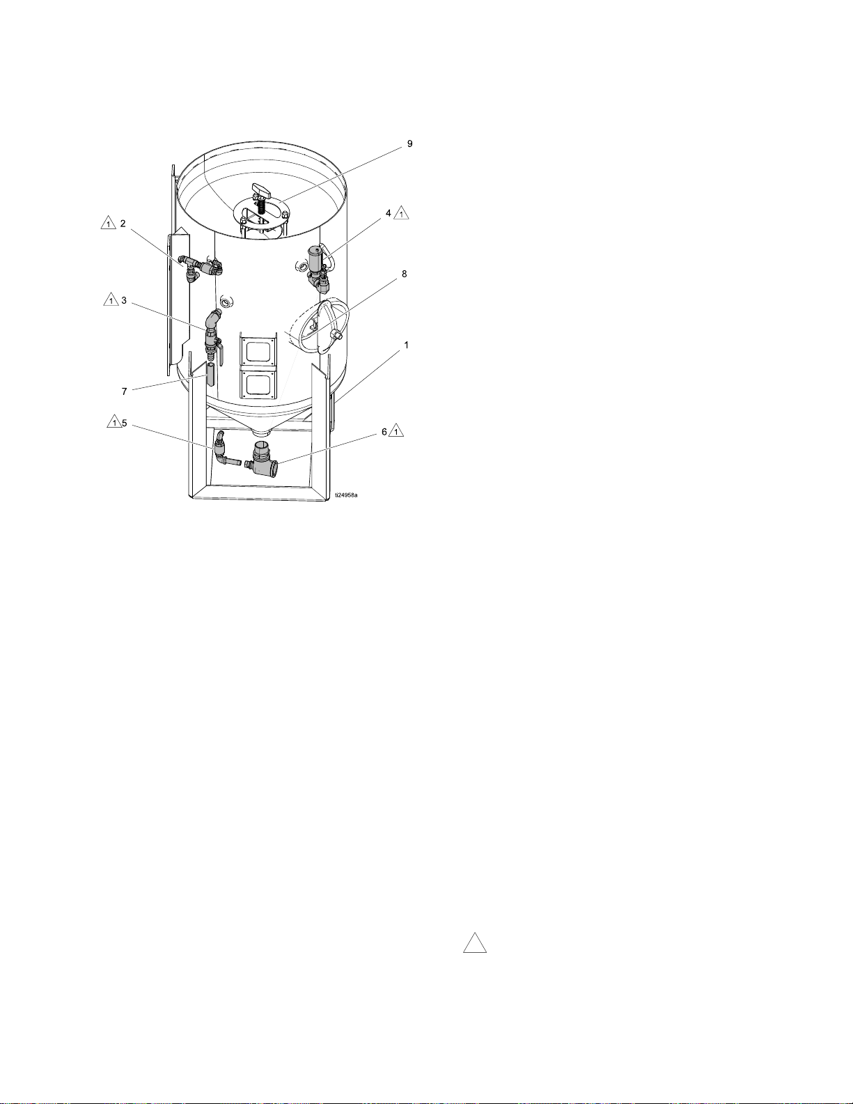
Parts
1
Pressure
Pressure Pressure
Pot
Pot Pot
Pressure
Pressure Pressure
Ref.
Ref. Ref.
1
2
3KIT,pressurepot,dump
Pot
Parts
Pot Pot
Parts Parts
Part
Part Part
102901TEE,pipe
123724
166469NIPPLE,pipe,hex
EQ1034
EQ1500FITTING,elbow,swivel,
EQ1834FITTING,connector,
EQ1778FITTING,elbow,street,
115813
190724NIPPLE,sst
EQ1003VALVE,ball,fullport,
EQ1012FITTING,nipple,barb,
List
List List
Description
Description Description
PRESSUREPOT,blast,
6.5cubicft.
KIT,pressurepot,ll
port
FITTING,nipple,hex,
1/2in.nptx3/8in.npt
VALVE,check,in-line,
ss316
male,3/8in.
straight,male
1/2npt,sst
valve
FITTING,streetelbow,
3/4in.npt
npt,ss
hose,3/4in.
Qty.
Qty. Qty.
1
1
1
Ref.
Ref. Ref.
Part
Part Part
4KIT,pressurepot,
17D785KIT,replacement,valve
115813
17D789KIT,replacement,valve,
123514
516308
5
EQ5137KIT,pressurepot,ush
6
EQ5148
7
EQ1360HOSE,clear,braided,
817D790KIT,replacement,
917D741KIT,replacement,
Applythreadsealanttopipethreads.
Description
Description Description
auto-vent
FITTING,streetelbow,
3/4npt
auto-vent
FITTING,tee,run,3/4
in.,mff,ss,3k
FITTING,bushing,
reducer,sst
valve
KIT,pressurepot,
unequaltee
3/4in.ID
handway
pop-up
Qty.
Qty. Qty.
1
1
1
3
1
1
334666B
41
Page 42
HoseSchematic
Hose
Hose Hose
Schematic
Schematic Schematic
Ref.
Ref. Ref.
28
29
35
35
35
35
37
37
39
Part
Part Part
EQ1296
EQ1882
EQ1273
EQ1273
EQ1273
EQ1273
EQ1297
EQ1273
EQ1881
Cut
Cut Cut
42.0in.
16.0in.
12.25in.
2.88in.
5.5in.
21.0in.
24.5in.
2.25in.
21.75in.
Length
Length Length
Ref.
Ref. Ref.
40
40
41
41
41
41
42
42
42
Part
Part Part
EQ1883
EQ1883
EQ1884
EQ1884
EQ1884
EQ1884
EQ1885
EQ1885
Cut
Cut Cut
20.75in.
11.25in.
19.88in.
32.0in.
7.38in.
10.5in.
34.5in.
17.0in.
Length
Length Length
334666B
Page 43

VaporAbrasiveBlastSystemsandAccessories
Vapor
Vapor Vapor
Systems
Systems Systems
EcoQuip
EcoQuip EcoQuip
Model
Model Model
EQ
EcoQuip
EcoQuip EcoQuip
Model
Model Model
EQ
Abrasive
Abrasive Abrasive
and
and and
Skid
Skid Skid
Series
Series Series
100M
1=100
3=300
6=600
Trailer
Trailer Trailer
Series
Series Series
2=200
series
4=400
series
Systems
Systems Systems
Package
Package Package
0=BarePackage(noblasthoseornozzle)M=Mobileunit(100seriesonly)
E=Completepackagewith15m(50ft)blasthose,
nozzle—ElectricBlastControl
P=CompletePackagewith15m(50ft)blasthose,
nozzle—PneumaticBlastControl
Systems
Systems Systems
Brakes
Brakes Brakes
2H03
H=HydraulicBrakes
available on 400 series)
E=ElectricBrakes
Blast
Blast Blast
Accessories
Accessories Accessories
(blast
hose
and
(blast (blast
hose hose
nozzle
and and
nozzle nozzle
Package
Package Package
(not
0=BarePackage
nozzle)
E=CompletePackage
m) blast hose, nozzle — Electric blast
control
P=CompletePackage
m) blast hose, nozzle — Pneumatic
blast control
type)
type) type)
(blasthoseandnozzletype)Compressor Compressor
(no blast hose or
Conguration
Conguration Conguration
S=SkidUnit(notavailableon
100series)
C=Nocrashframeorwatertank
(notavailableon100series)
with 50 ft (15
with 50 ft (15
Compressor
Conguration
Conguration Conguration
3=Tier3Compliant
(only available on
400 series)
4=Tier4iCompliant
334666B 43
Page 44

VaporAbrasiveBlastSystemsandAccessories
Mobile/Skid
Mobile/Skid Mobile/Skid
Model
Model Model
EQ100M100Series
EQ10EM100Series
EQ10PM100Series
Model
Model Model
EQ300S300Series
EQ300C300SeriesNoskid/crashframeorwatertank,barepackage
EQ30ES300SeriesCompletepackage,electricblastcontrol
EQ30EC300SeriesNoskid/crashframeorwatertank,completepackage,electricblastcontrol
EQ30PS300SeriesCompletepackage,pneumaticblastcontrol
EQ30PC300SeriesNoskid/crashframeorwatertank,completepackage,pneumaticblastcontrol
Model
Model Model
EQ600S600Series
EQ600C600SeriesNoskid/crashframeorwatertank,barepackage
EQ60ES600SeriesCompletepackage,electricblastcontrol
EQ60EC600SeriesNoskid/crashframeorwatertank,completepackage,electricblastcontrol
EQ60PS600SeriesCompletepackage,pneumaticblastcontrol
EQ60PC600SeriesNoskid/crashframeorwatertank,completepackage,pneumaticblastcontrol
Units
Units Units
Series
Series Series
Series
Series Series
Series
Series Series
Description
Description Description
Mobileunit,barepackage
Mobileunit,completepackage,electricblastcontrol
Mobileunit,completepackage,pneumaticblastcontrol
Description
Description Description
Barepackage
Description
Description Description
Barepackage
100/300 complete packages include 1 in. ID, 4 –ply hose (15 meter long) and #7 standard nozzle.
600 complete packages include 1.25 in. ID, 2–ply hose and #8 high performance nozzle.
Trailer
Trailer Trailer
Model
Model Model
EQ2H04
EQ2HE4
EQ2HP4
EQ2E04
EQ2EE4
EQ2EP4
EQ4E03
EQ4EE3
EQ4EP3
EQ4E04
EQ4EE4
EQ4EP4
Units
Units Units
Description
Description Description
200series,hydraulicbrakes,barepackage,Tier4i
200series,hydraulicbrakes,completepackage,electricblastcontrol,Tier4i
200series,hydraulicbrakes,completepackage,Tier4i
200series,electricbrakes,barepackage,Tier4i
200series,electricbrakes,completepackage,electricblastcontrol,Tier4i
200series,electricbrakes,completepackage,pneumaticblastcontrol,Tier4i
400series,electricbrakes,barepackage,Tier3
400series,electricbrakes,completepackageelectricblastcontrol,Tier3
400series,electricbrakes,completepackagepneumaticblastcontrol,Tier3
400series,electricbrakes,barepackage,Tier4i
400series,electricbrakes,electricblastcontrol,Tier4i
400series,electricbrakes,completepackage,pneumaticblastcontrol,Tier4i
44
334666B
Page 45

VaporAbrasiveBlastSystemsandAccessories
Hoses
Hoses Hoses
Model
Model Model
EQ5237
EQ5235
EQ5236
EQ5234
EQ5077
EQ5084
EQ5082
EQ5073
EQ5071
EQ5080
Model
Model Model
17D786Hoserestraint
17D787
17C459
17C124
17C125Gasket,cam/groove,abrasiveblastline–1.25in.ID(EQ300)
17C453Gasket,cam/groove,abrasiveblastline–1.5in.ID(EQ600)
EQ5183Cable,battery
17D788Replacementhandle,pneumaticblastcontrol
17D791Replacementhandle,electricblastcontrol
Description
Description Description
BlastHoseExtension
BlastHoseExtension
BlastHoseReplacement
BlastHoseReplacement
BlastHoseExtension
BlastHoseExtension
BlastHoseExtension
BlastHoseExtension
BlastHoseReplacement
BlastHoseReplacement
Description
Description Description
Couplerpin
Blasthosecouplergasket,hoseend
Blasthosecouplergasket,machineend
Type
Type Type
Length
Length Length
15m(50ft)
15m(50ft)
15m(50ft)
15m(50ft)
30m(100ft)
30m(100ft)
15m(50ft)
15m(50ft)
15m(50ft)
15m(50ft)
Blast
Control
Blast Blast
Control Control
Pneumatic1.0in.
Electric1.0in.
Pneumatic1.0in.
Electric1.0in.
Pneumatic1.25in.
Electric1.25in.
Electric1.25in.
Pneumatic1.25in.
Pneumatic1.25in.
Electric1.25in.
ID
ID ID
Model
Model Model
EQ100,
EQ200,
EQ300
EQ400,
EQ600
Nozzles
Nozzles Nozzles
Model
Model Model
EQ1710Standard#7(EQ100,EQ300,EQ200T)
EQ1711Standard#8(EQ600,EQ400T)
EQ7073*Highperformance#7(EQ100,EQ300,EQ200T)
EQ7074*Highperformance#8(EQ600,EQ400T)
EQ5166
Description
Description Description
Nozzleextension,24in.
*Performance nozzles require 100 psi (7 bar, 0.7
MPa) or more air pressure at nozzle.
334666B 45
Page 46

VaporAbrasiveBlastSystemsandAccessories
Common
Common Common
Model
Model Model
17B186KIT,repair,pump
17C124
17C125
17C127KIT,repair,diaphragmvalve(EQ300)
17C128KIT,repair,diaphragmvalve(EQ100,EQ600)
17C129KIT,repair,regulator,air(EQ100)
17C131KIT,repair,regulator,air(EQ600)
17C453
17C459
17D790
17D789VALVE,auto-vent,3/4in.
17D785
17D786KIT,replacement,hoserestraint
17D787KIT,replacement,couplerpin
206994
Other
Other Other
Spare
Spare Spare
Accessories
Accessories Accessories
Parts
Parts Parts
Description
Description Description
KIT,gasket,hosecoupler
KIT,gasket,quickcoupler
KIT,gasket,quickcoupler
KIT,gasket,hosecoupler
GASKET,handway6in.x8in.blackne
KIT,replacement,pressurereliefvalve
ThroatSealLiquid
Model
Model Model
17C126PumpRetrotKit
24A592
Description
Description Description
DataTrakModuleandReedSwitch
46 334666B
Page 47
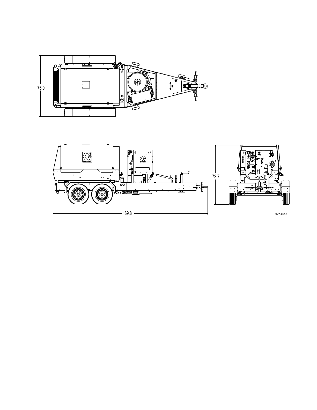
Dimensions
Dimensions
Dimensions Dimensions
334666B
47
Page 48

TechnicalSpecications
Technical
Technical Technical
EQ200T
EQ200T EQ200T
MaximumWorkingPressure125psi8.6bar,0.86MPa
OperatingTemperature35°–110°F1.6°–43.3°C
AirConsumption165–375cfm
BlastHoseSize
AbrasiveCapacity
GVWR
PressurePotVolume
WaterTankVolume100gallon378liters
Sound
Sound Sound
SoundPressureLevel133dB(A)133dB(A)
SoundPowerLevel139dB(A)139dB(A)
InstantaneousSoundPressureLevel131dB(C)131dB(C)
*All readings were taken at the maximum system blast pressure 125 psi (8.6 bar, 0.86 MPa) from the operator
position. The abrasive used was garnet and the substrate was steel. Tested in accordance with ISO 9614–2.
EQ400T
EQ400T EQ400T
MaximumWorkingPressure125psi8.6bar,0.86MPa
OperatingTemperature35°–110°F1.6°–43.3°C
AirConsumption375–600cfm
BlastHoseSize
AbrasiveCapacity
GVWR
PressurePotVolume
WaterTankVolume130gallon492liters
Sound
Sound Sound
SoundPressureLevel133dB(A)133dB(A)
SoundPowerLevel139dB(A)139dB(A)
InstantaneousSoundPressureLevel131dB(C)131dB(C)
*All readings were taken at the maximum system blast pressure 125 psi (8.6 bar, 0.86 MPa) from the operator
position. The abrasive used was garnet and the substrate was steel. Tested in accordance with ISO 9614–2.
Data*
Data* Data*
Data*
Data* Data*
Specications
Specications Specications
U.S.
U.S. U.S.
4.67–10.62m^3/min
1in.ID25.4mmID
400–500lb181–227kg
6160lb2794kg
6.5cubicfeet
U.S.
U.S. U.S.
10.62–17.0m^3/min
1.25in.ID31.75mmID
400–500lb181–227kg
11000lb4990kg
6.5cubicfeet
Metric
Metric Metric
184liters
Metric
Metric Metric
184liters
48 334666B
Page 49

Notes
Notes
Notes Notes
334666B 49
Page 50

Graco
Graco Graco
Components
Components Components
GracowarrantsallequipmentreferencedinthisdocumentwhichismanufacturedbyGracoandbearingthe
GracoorEcoQuipnametobefreefromdefectsinmaterialandworkmanshiponthedateofsaletotheoriginal
purchaserforuse.Gracowill,forthree(3)yearsfromthedateofsale,repairorreplaceanypartofthe
equipmentdeterminedbyGracotobedefective.Thiswarrantyappliesonlywhentheequipmentisinstalled,
operatedandmaintainedinaccordancewithGraco’swrittenrecommendations.
Thiswarrantydoesnotcover,andGracoshallnotbeliableforgeneralwearandtear,oranymalfunction,
damageorwearcausedbyfaultyinstallation,misapplication,abrasion,corrosion,inadequateorimproper
maintenance,negligence,accident,tampering,orsubstitutionofnon-Gracocomponentparts.NorshallGraco
beliableformalfunction,damageorwearcausedbytheincompatibilityofGracoequipmentwithstructures,
accessories,equipmentormaterialsnotsuppliedbyGraco,ortheimproperdesign,manufacture,installation,
operationormaintenanceofstructures,accessories,equipmentormaterialsnotsuppliedbyGraco.
Thiswarrantyisconditionedupontheprepaidreturnoftheequipmentclaimedtobedefectivetoanauthorized
Gracodistributorforvericationoftheclaimeddefect.Iftheclaimeddefectisveried,Gracowillrepairorreplace
freeofchargeanydefectiveparts.Theequipmentwillbereturnedtotheoriginalpurchasertransportation
prepaid.Ifinspectionoftheequipmentdoesnotdiscloseanydefectinmaterialorworkmanship,repairswillbe
madeatareasonablecharge,whichchargesmayincludethecostsofparts,labor,andtransportation.
THIS
WARRANTY
THIS THIS
WARRANTY WARRANTY
INCLUDING
INCLUDING INCLUDING
FOR
FOR FOR
A AAPARTICULAR PARTICULAR
Graco’ssoleobligationandbuyer’ssoleremedyforanybreachofwarrantyshallbeassetforthabove.The
buyeragreesthatnootherremedy(including,butnotlimitedto,incidentalorconsequentialdamagesforlost
prots,lostsales,injurytopersonorproperty,oranyotherincidentalorconsequentialloss)shallbeavailable.
Anyactionforbreachofwarrantyhereundermustbebroughtwithinthelatteroftwo(2)yearsofthedateofsale,
orone(1)yearafterthewarrantyperiodexpires.
GRACO
GRACO GRACO
AND
FITNESS
AND AND
FITNESS FITNESS
MATERIALS
MATERIALS MATERIALS
manufactured
manufactured manufactured
hose
hose hose
or ororother other
provide
provide provide
InnoeventwillGracobeliableforindirect,incidental,specialorconsequentialdamagesresultingfromGraco
supplyingequipmenthereunder,orthefurnishing,performance,oruseofanyproductsorothergoodssold
hereto,whetherduetoabreachofcontract,breachofwarranty,thenegligenceofGraco,orotherwise.
FORGRACOCANADACUSTOMERS
ThePartiesacknowledgethattheyhaverequiredthatthepresentdocument,aswellasalldocuments,notices
andlegalproceedingsenteredinto,givenorinstitutedpursuantheretoorrelatingdirectlyorindirectlyhereto,be
drawnupinEnglish.Lespartiesreconnaissentavoirconvenuquelarédactionduprésentedocumentseraen
Anglais,ainsiquetousdocuments,avisetprocéduresjudiciairesexécutés,donnésouintentés,àlasuitedeou
enrapport,directementouindirectement,aveclesprocéduresconcernées.
Extended
Extended Extended
IS
EXCLUSIVE,
IS IS
BUT
BUT BUT
PARTICULAR
MAKES
MAKES MAKES
OR
OR OR
by
by by
other
hose
hose hose
purchaser
purchaser purchaser
EXCLUSIVE, EXCLUSIVE,
NOT
LIMITED
NOT NOT
LIMITED LIMITED
PURPOSE.
PURPOSE. PURPOSE.
NO
WARRANTY,
NO NO
WARRANTY, WARRANTY,
FOR
FOR FOR
PARTICULAR
A AAPARTICULAR PARTICULAR
COMPONENTS
COMPONENTS COMPONENTS
Graco
(such
Graco Graco
(such (such
and
blast
and and
with
with with
nozzles),
blast blast
nozzles), nozzles),
reasonable
reasonable reasonable
Warranty
Warranty Warranty
AND
IS
IN
AND AND
TO
WARRANTY
TO TO
WARRANTY WARRANTY
AND
AND AND
PURPOSE,
PURPOSE, PURPOSE,
SOLD
SOLD SOLD
as
electric
as as
electric electric
are
are are
assistance
assistance assistance
LIEU
IS IS
IN IN
LIEU LIEU
OF
OF OF
DISCLAIMS
DISCLAIMS DISCLAIMS
BUT
BUT BUT
motors,
motors, motors,
subject
subject subject
IN
IN IN
NOT
NOT NOT
switches,
switches, switches,
making
in ininmaking making
for
for for
OF
ANY
OF OF
ANY ANY
MERCHANTABILITY
MERCHANTABILITY MERCHANTABILITY
ALL
ALL ALL
CONNECTION
CONNECTION CONNECTION
MANUFACTURED
MANUFACTURED MANUFACTURED
the
warranty,
to totothe the
warranty, warranty,
any
any any
EcoQuip
EcoQuip EcoQuip
OTHER
OTHER OTHER
IMPLIED
IMPLIED IMPLIED
compressors,
compressors, compressors,
claim
claim claim
WARRANTIES,
WARRANTIES, WARRANTIES,
OR
OR OR
WARRANTIES
WARRANTIES WARRANTIES
WITH
ACCESSORIES,
WITH WITH
ACCESSORIES, ACCESSORIES,
BY
GRACO.
BY BY
GRACO. GRACO.
engines,
engines, engines,
any,
if ififany, any,
of ofoftheir their
for
breach
for for
breach breach
™
™ ™
EXPRESS
EXPRESS EXPRESS
WARRANTY
WARRANTY WARRANTY
OF
MERCHANTABILITY
OF OF
MERCHANTABILITY MERCHANTABILITY
These
These These
trailer
components,
trailer trailer
their
manufacturer.
manufacturer. manufacturer.
these
of ofofthese these
components, components,
warranties.
warranties. warranties.
OR
IMPLIED,
OR OR
OF
OF OF
EQUIPMENT,
EQUIPMENT, EQUIPMENT,
items
items items
IMPLIED, IMPLIED,
FITNESS
FITNESS FITNESS
sold,
but
sold, sold,
but but
blast
blast blast
Graco
will
Graco Graco
will will
not
not not
Graco
Graco Graco
ForthelatestinformationaboutGracoproducts,visitwww.graco.com.
Forpatentinformation,seewww.graco.com/patents.
To
To To
Phone:
Phone: Phone:
Allwrittenandvisualdatacontainedinthisdocumentreectsthelatestproductinformationavailableatthetimeofpublication.
Information
Information Information
place
an
place place
an an
612-623-6921or ororToll Toll
order,
order, order,
contactyourGracoDistributororcalltoidentifythenearestdistributor.
Toll
Free:
Free: Free:
1-800-328-0211Fax: Fax:
Gracoreservestherighttomakechangesatanytimewithoutnotice.
OriginalInstructions.ThismanualcontainsEnglish.MM334666
Graco
Graco Graco
International
International International
GRACO
GRACO GRACO
INC.
AND
INC. INC.
Copyright
Copyright Copyright
SUBSIDIARIES
AND AND
SUBSIDIARIES SUBSIDIARIES
2014,
Graco
2014, 2014,
Inc.
Graco Graco
Inc. Inc.
Ofces:
Ofces: Ofces:
• ••P.O. P.O.
All
Graco
All All
Graco Graco
RevisionB,December2014
Fax:
Headquarters:
Headquarters: Headquarters:
Belgium,China,Japan,Korea
P.O.
BOX
BOX BOX
manufacturing
manufacturing manufacturing
www.graco.com
612-378-3505
Minneapolis
1441
MINNEAPOLIS
1441 1441
• ••MINNEAPOLIS MINNEAPOLIS
locations
locations locations
MN
MN MN
are
registered
are are
registered registered
55440-1441
55440-1441 55440-1441
ISO
to totoISO ISO
USA
• ••USA USA
9001.
9001. 9001.
 Loading...