

Page 1
Instructions - Parts
3A2012J
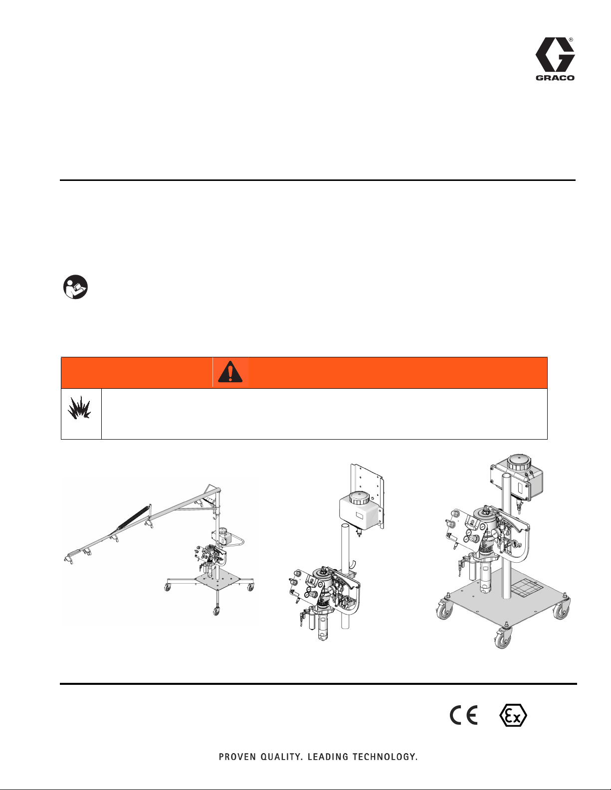
FRP Proportioner
Low emission internal/external mix gel coat and chop proportioners. For use with resin
and catalyst in hazardous and non-hazardous locations.
For professional use only.
Important Safety Instructions
Read all warnings and instructions in this manual and
all component manuals. Save all instructions.
See page 4 for model and agency approvals information. See page 83 for maximum working pressure and other
specifications. For patent information, see www.graco.com/patents.
EN
WARNING
FIRE AND EXPLOSION HAZARD
Oil left in the system at the factory can react with catalyst and create a fire or explosion.
• Flush before first use.
• Do not add catalyst to the catalyst reservoir until the system has been flushed.
ti18526c
ti18524d
Wall Mount SystemCart and Boom System
Cart System
ti18496b
II 2 Gc T5
Page 2

Contents
Related Manuals . . . . . . . . . . . . . . . . . . . . . . . . . . . 3
Agency Approvals . . . . . . . . . . . . . . . . . . . . . . . . . . 3
Models . . . . . . . . . . . . . . . . . . . . . . . . . . . . . . . . . . . 4
Accessories . . . . . . . . . . . . . . . . . . . . . . . . . . . . . . . 5
Warnings . . . . . . . . . . . . . . . . . . . . . . . . . . . . . . . . . 6
Important Methyl Ethyl Ketone Peroxide (MEKP)
Safety Information . . . . . . . . . . . . . . . . . . . . . . 8
Important Two-Component Material Information . 9
Material Self-ignition . . . . . . . . . . . . . . . . . . . . . . 9
Keep Resin and Catalyst Components Separate 9
Changing Materials . . . . . . . . . . . . . . . . . . . . . . . 9
Overview . . . . . . . . . . . . . . . . . . . . . . . . . . . . . . . . . 10
Component Identification . . . . . . . . . . . . . . . . . . 11
Air Control Panel . . . . . . . . . . . . . . . . . . . . . . . . 12
Air Motor and Resin Displacement Pump . . . . . 13
Catalyst Pump . . . . . . . . . . . . . . . . . . . . . . . . . . 14
Solvent Flush Systems . . . . . . . . . . . . . . . . . . . 15
Setup . . . . . . . . . . . . . . . . . . . . . . . . . . . . . . . . . . . . 16
Before Installation . . . . . . . . . . . . . . . . . . . . . . . 16
Location Requirements . . . . . . . . . . . . . . . . . . . 16
System Mounting (Wall Mount Systems Only) . 16
System Assembly . . . . . . . . . . . . . . . . . . . . . . . 18
Grounding . . . . . . . . . . . . . . . . . . . . . . . . . . . . . 20
Connect Fluid and Air Lines . . . . . . . . . . . . . . . 21
Flush Before First Use . . . . . . . . . . . . . . . . . . . 23
Fill Supply Tanks . . . . . . . . . . . . . . . . . . . . . . . . 23
Operation . . . . . . . . . . . . . . . . . . . . . . . . . . . . . . . . 24
Trigger Lock . . . . . . . . . . . . . . . . . . . . . . . . . . . 24
Boom Operation . . . . . . . . . . . . . . . . . . . . . . . . 24
Pressure Relief Procedure and Shutdown . . . . 24
Startup . . . . . . . . . . . . . . . . . . . . . . . . . . . . . . . 26
Prime . . . . . . . . . . . . . . . . . . . . . . . . . . . . . . . . 27
Flush . . . . . . . . . . . . . . . . . . . . . . . . . . . . . . . . . 30
Spray . . . . . . . . . . . . . . . . . . . . . . . . . . . . . . . . . 31
DataTrak Operation . . . . . . . . . . . . . . . . . . . . . 33
Replace DataTrak Battery or Fuse . . . . . . . . . . 38
Maintenance . . . . . . . . . . . . . . . . . . . . . . . . . . . . . . 39
Components . . . . . . . . . . . . . . . . . . . . . . . . . . . 39
Troubleshooting . . . . . . . . . . . . . . . . . . . . . . . . . . 40
Catalyst Pump . . . . . . . . . . . . . . . . . . . . . . . . . . 40
Resin Pump . . . . . . . . . . . . . . . . . . . . . . . . . . . 40
Repair . . . . . . . . . . . . . . . . . . . . . . . . . . . . . . . . . . . 42
General Information . . . . . . . . . . . . . . . . . . . . . . 42
Disconnect the Displacement Pump . . . . . . . . . 42
Reconnect the Displacement Pump . . . . . . . . . 43
Disconnect the Air Motor . . . . . . . . . . . . . . . . . . 44
Reconnect the Air Motor . . . . . . . . . . . . . . . . . . 44
Replace Pumpline . . . . . . . . . . . . . . . . . . . . . . . 46
Repair Catalyst Pump . . . . . . . . . . . . . . . . . . . . 47
System Parts . . . . . . . . . . . . . . . . . . . . . . . . . . . . . 50
Systems . . . . . . . . . . . . . . . . . . . . . . . . . . . . . . . 50
Carts . . . . . . . . . . . . . . . . . . . . . . . . . . . . . . . . . 55
Wall or Pole Mount Kit, 16N918 . . . . . . . . . . . . 57
Boom, 16N761 . . . . . . . . . . . . . . . . . . . . . . . . . . 58
Air Panel . . . . . . . . . . . . . . . . . . . . . . . . . . . . . . 59
Slave Pump Linkage, 16P125 . . . . . . . . . . . . . . 60
Resin Pumplines . . . . . . . . . . . . . . . . . . . . . . . . 61
Air Motor and Pump for
Resin Pumpline . . . . . . . . . . . . . . . . . . . . . . 62
Gun . . . . . . . . . . . . . . . . . . . . . . . . . . . . . . . . . . 62
Resin Filter . . . . . . . . . . . . . . . . . . . . . . . . . . . . 63
Resin Supply Hose . . . . . . . . . . . . . . . . . . . . . . 64
Catalyst Slave Pumps . . . . . . . . . . . . . . . . . . . 66
Catalyst Reservoir . . . . . . . . . . . . . . . . . . . . . . . 68
Hose Bundles . . . . . . . . . . . . . . . . . . . . . . . . . . 70
Hose Bundles . . . . . . . . . . . . . . . . . . . . . . . . . . 71
Accessory Parts . . . . . . . . . . . . . . . . . . . . . . . . . 72
Heater Kits . . . . . . . . . . . . . . . . . . . . . . . . . . . . . 72
Solvent Pressure Pot Kits . . . . . . . . . . . . . . . . . 74
Solvent Diaphragm Pumps . . . . . . . . . . . . . . . . 76
DataTrak Upgrade Kit . . . . . . . . . . . . . . . . . . . . 77
Carts for 55 Gallon Barrel, 16M896 . . . . . . . . . 78
Roving Box Bracket . . . . . . . . . . . . . . . . . . . . . . 79
Extension Hoses . . . . . . . . . . . . . . . . . . . . . . . . 80
Dimensions . . . . . . . . . . . . . . . . . . . . . . . . . . . . . . . 81
Cart and Boom . . . . . . . . . . . . . . . . . . . . . . . . . 81
Cart Only . . . . . . . . . . . . . . . . . . . . . . . . . . . . . . 82
Wall/Pole Mount . . . . . . . . . . . . . . . . . . . . . . . . 82
Pumpline Wall Mounting Bracket Dimensions . . 83
Technical Data . . . . . . . . . . . . . . . . . . . . . . . . . . . . 83
Graco Standard Warranty . . . . . . . . . . . . . . . . . . . 86
2 3A2012J
Page 3
Related Manuals
Related Manuals
Manuals are available at www.graco.com. Component
manuals in English:
Manual Description
™
3A0232 RS
3A2313 U-Cup Displacement Pump
3A2315 NXT
332451 FRP Stainless Steel Fitting Kit
308981 Air Operated Diaphragm Pumps
309524 Viscon HP Heater Instructions
307363 Viscon
313541 DataTrak
308370
307273 Fluid Outlet Filter
407019 Chop Cart Legs Kit
Gun Instructions-Parts
®
Air Motor for FRP
®
Heater Instructions
™
Conversion Kit Instructions
ASME and CE-Approved Pressure Pot
Instructions (Solvent Flush Pressure Pot)
Agency Approvals
Manual Description
407020 55 Gallon Drum Kit
407021 Roving Box Bracket Kit
407022 Deluxe Inlet Seat Removal Tool
407023 5 Gallon Catalyst Reservoir Kit
407024 Boom Kit
407025 DataTrak
407026 Wall or Pole Mount Kit
407027 Linkage Replacement Kit
407028 Resin Pump Connecting Kit
407031 Diaphragm Pump Solvent Flush Kit
Non-CE Approved Solvent Pressure Pot
407032
407033
407042 Heater Kits
Kits
ASME and CE-Approved Pressure Pot
Kits
™
Upgrade Kit
FRP proportioner systems are approved for use in
hazardous locations when the base model, all accessories, and all kits meet all wiring meet local, state,
and national codes.
Base FRP System with no accessories*
Accessories
* Solvent pots do not affect Atex rating.
II 2 Gc T5
See accessory manuals listed in Related Manuals section for approvals.
3A2012J 3
Page 4

Models
Models
Internal or
Ratio
Internal Mix
13:1
Internal Mix
17:1
External
Mix
External
Mix
External
Mix
Gel or
Chop
Gel
Chop
Gel
Chop
Gel
Gel
No Cart Cart Cart, Mast, and Boom
Hose
Length
Part No.
16R065 25 (7.6) 16R002 25 (7.6) 16R053 25 (7.6)
16R068 35 (10.7) 16R044 35 (10.7) 16R056 35 (10.7)
16R071 50 (15.2) 16R047 50 (15.2) 16R059 50 (15.2)
16R074 --- 16R050 --- 16R062 ---
16R135 25 (7.6) 16R123 25 (7.6) 16R004 25 (7.6)
16R138 35 (10.7) 16R114 35 (10.7) 16R126 35 (10.7)
16R141 50 (15.2) 16R117 50 (15.2) 16R129 50 (15.2)
16R144 --- 16R120 --- 16R132 ---
16R030 25 (7.6) 16R001 25 (7.6) 16R018 25 (7.6)
16R033 35 (10.7) 16R009 35 (10.7) 16R021 35 (10.7)
16R036 50 (15.2) 16R012 50 (15.2) 16R024 50 (15.2)
16R039 --- 16R015 --- 16R027 ---
16R100 25 (7.6) 16R088 25 (7.6) 16R003 25 (7.6)
16R103 35 (10.7) 16R079 35 (10.7) 16R091 35 (10.7)
16R106 50 (15.2) 16R082 50 (15.2) 16R094 50 (15.2)
16R109 --- 16R085 --- 16R097 ---
16R205 25 (7.6) 16R006 25 (7.6) 16R193 25 (7.6)
16R208 35 (10.7) 16R184 35 (10.7) 16R196 35 (10.7)
16R211 50 (15.2) 16R187 50 (15.2) 16R199 50 (15.2)
16R214 --- 16R190 --- 16R202 ---
16R170 25 (7.6) 16R005 25 (7.6) 16R158 25 (7.6)
16R173 35 (10.7) 16R149 35 (10.7) 16R161 35 (10.7)
16R176 50 (15.2) 16R152 50 (15.2) 16R164 50 (15.2)
16R179 --- 16R155 --- 16R167 ---
ft (m) Part No.
Hose
Length
ft (m) Part No.
Hose
Length
ft (m)
4 3A2012J
Page 5
Accessories
To avoid fire and explosion and electric shock, FRP
proportioners are not approved for use in hazardous
locations unless all accessories, all kits, and all wiring
meet local, state, and national codes. See Agency
Approvals on page 3.
Accessories
The following items can be purchased separately from
the system to gain additional functions. Many of the
items require user installation; refer to the System
Assembly section beginning on page 18 for the
required procedures.
Solvent Flush Diaphragm Pumps
Part Description
16M560 2 Gallon Solvent Flush Diaphragm Pump
16M561 5 Gallon Solvent Flush Diaphragm Pump
Solvent Flush Pressure Pots
Part Description
16M874
16M875
16M893 2 Gallon, ASME Solvent Flush Pressure Pot
16M894 5 Gallon, ASME Solvent Flush Pressure Pot
Heaters
Part Description
16N014★
16N015★
16N016
16N017
16N018
16N019
★
2 Gallon, ASME and CE-approved, Solvent
Flush Pressure Pot
5 Gallon, ASME and CE-approved, Solvent
Flush Pressure Pot
120V Viscon Heater, for hazardous locations
240V Viscon Heater, for hazardous locations
120V Viscon Heater, for hazardous locations and explosive atmospheres
240V Viscon Heater, for hazardous locations and explosive atmospheres
120V Viscon Heater, for non-hazardous
locations
240V Viscon Heater, for non-hazardous
locations
Heaters can be disassembled to remove
cured material.
Extension Hoses
Part Description
16M712
16M718
16M719
55 Gallon Barrel Carts
Part Description
16M896 55 Gallon Barrel Cart
Roving Box Bracket
Part Description
16M961 Roving Box Bracket Kit
DataTrak Upgrade
Part Description
16M881 DataTrak Upgrade Kit
5 Gallon Catalyst Reservoir
Part Description
24M501 5 Gallon Catalyst Reservoir Kit
Wall Mounting
Part Description
16N918 FRP Pole or Wall Mount Kit
Pump Connecting Kits
Part Description
16N242 17:1 Pump Connecting Kit
16N243 13:1 Pump Connecting Kit
25 ft Extension Hose Bundle for Chop Systems
25 ft Extension Hose Bundle for Internal Gel
Systems
25 ft Extension Hose Bundle for External
Gel Systems
3A2012J 5
Page 6
Warnings
Warnings
The following warnings are for the setup, use, grounding, maintenance, and repair of this equipment. The exclamation point symbol alerts you to a general warning and the hazard symbols refer to procedure-specific risks. When
these symbols appear in the body of this manual, refer back to these Warnings. Product-specific hazard symbols and
warnings not covered in this section may appear throughout the body of this manual where applicable.
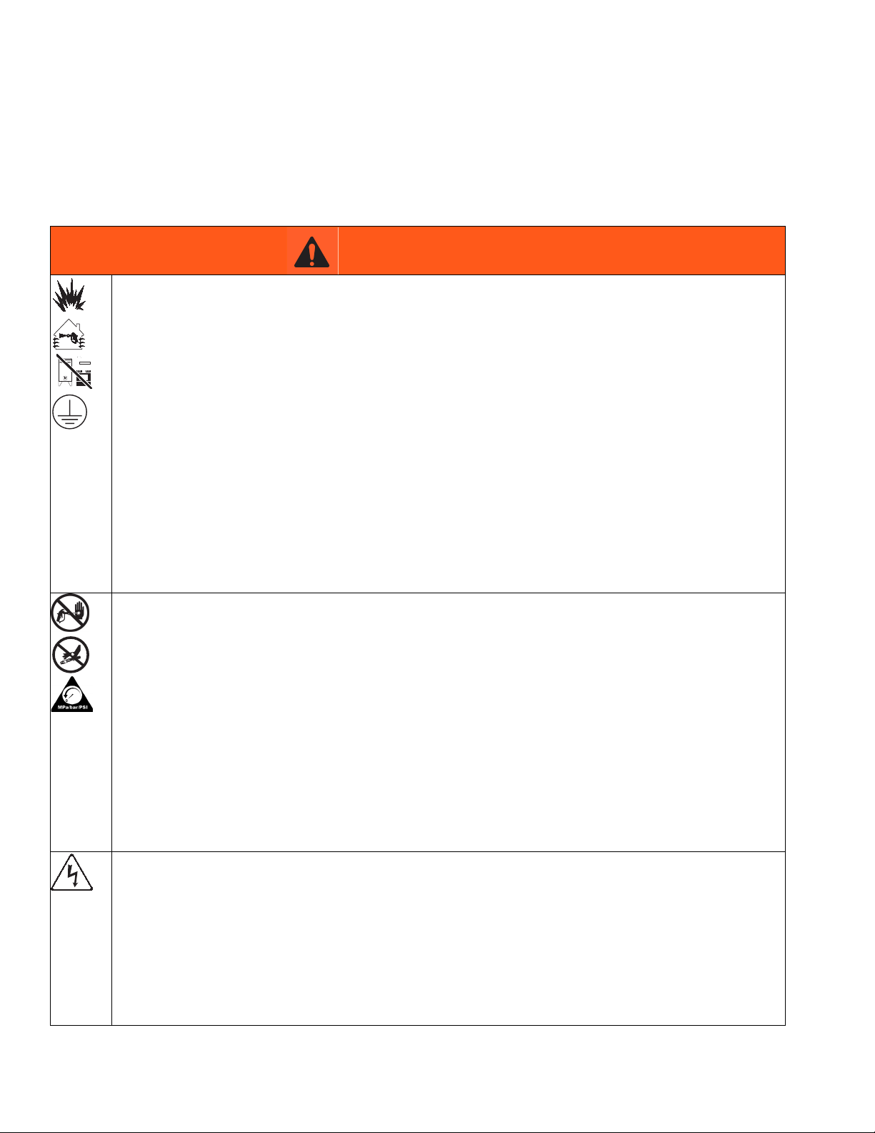
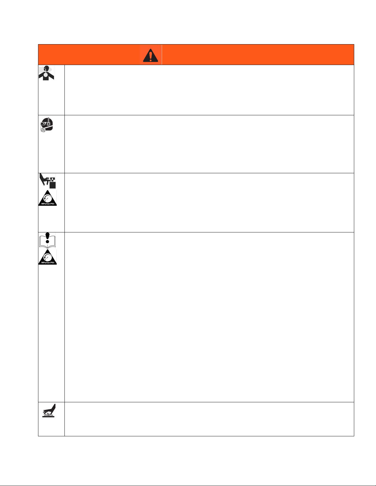
WARNING
FIRE AND EXPLOSION HAZARD
Flammable fumes, such as solvent and paint fumes, in work area can ignite or explode. To help prevent
fire and explosion:
• Use equipment only in well ventilated area.
• Eliminate all ignition sources; such as pilot lights, cigarettes, portable electric lamps, and plastic drop
cloths (potential static arc).
• Keep work area free of debris, including solvent, rags and gasoline.
• Do not plug or unplug power cords, or turn power or light switches on or off when flammable fumes are
present.
• Ground all equipment in the work area. See Grounding instructions.
• Use only grounded hoses.
• Hold gun firmly to side of grounded pail when triggering into pail.
• If there is static sparking or you feel a shock, stop operation immediately. Do not use equipment until
you identify and correct the problem.
• Keep a working fire extinguisher in the work area.
SKIN INJECTION HAZARD
High-pressure fluid from dispensing device, hose leaks, or ruptured components will pierce skin. This may
look like just a cut, but it is a serious injury that can result in amputation. Get immediate surgical
treatment.
• Engage trigger lock when not dispensing.
• Do not point dispensing device at anyone or at any part of the body.
• Do not put your hand over the fluid outlet.
• Do not stop or deflect leaks with your hand, body, glove, or rag.
• Follow the Pressure Relief Procedure when you stop dispensing and before cleaning, checking, or
servicing equipment.
• Tighten all fluid connections before operating the equipment.
• Check hoses and couplings daily. Replace worn or damaged parts immediately.
ELECTRIC SHOCK HAZARD
This equipment must be grounded. Improper grounding, setup, or usage of the system can cause electric
shock.
• Turn off and disconnect power at main switch before disconnecting any cables and before servicing
equipment.
• Connect only to grounded power source.
• All electrical wiring must be done by a qualified electrician and comply with all local codes and
regulations.
6 3A2012J
Page 7
Warnings
WARNING
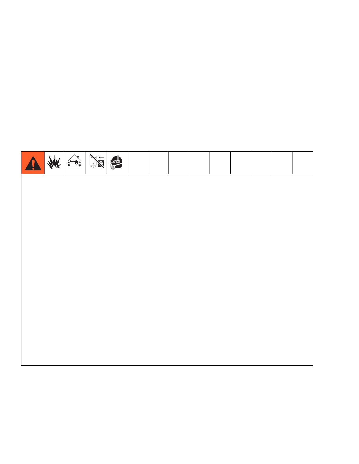
TOXIC FLUID OR FUMES HAZARD
Toxic fluids or fumes can cause serious injury or death if splashed in the eyes or on skin, inhaled, or
swallowed.
• Read MSDSs to know the specific hazards of the fluids you are using.
• Store hazardous fluid in approved containers, and dispose of it according to applicable guidelines.
PERSONAL PROTECTIVE EQUIPMENT
You must wear appropriate protective equipment when operating, servicing, or when in the operating area
of the equipment to help protect you from serious injury, including eye injury, hearing loss, inhalation of
toxic fumes, and burns. This equipment includes but is not limited to:
• Protective eyewear, and hearing protection.
• Respirators, protective clothing, and gloves as recommended by the fluid and solvent manufacturer.
MOVING PARTS HAZARD
Moving parts can pinch, cut or amputate fingers and other body parts.
• Keep clear of moving parts.
• Do not operate equipment with protective guards or covers removed.
• Pressurized equipment can start without warning. Before checking, moving, or servicing equipment,
follow the Pressure Relief Procedure and disconnect all power sources.
EQUIPMENT MISUSE HAZARD
Misuse can cause death or serious injury.
• Do not operate the unit when fatigued or under the influence of drugs or alcohol.
• Do not exceed the maximum working pressure or temperature rating of the lowest rated system
component. See Technical Data in all equipment manuals.
• Use fluids and solvents that are compatible with equipment wetted parts. See Technical Data in all
equipment manuals. Read fluid and solvent manufacturer’s warnings. For complete information about
your material, request MSDS from distributor or retailer.
• Do not leave the work area while equipment is energized or under pressure. Turn off all equipment and
follow the Pressure Relief Procedure when equipment is not in use.
• Check equipment daily. Repair or replace worn or damaged parts immediately with genuine
manufacturer’s replacement parts only.
• Do not alter or modify equipment. Alterations or modifications may void agency approvals and create
safety hazards.
• Use equipment only for its intended purpose. Call your distributor for information.
• Route hoses and cables away from traffic areas, sharp edges, moving parts, and hot surfaces.
• Do not kink or over bend hoses or use hoses to pull equipment.
• Keep children and animals away from work area.
• Comply with all applicable safety regulations.
BURN HAZARD
Equipment surfaces and fluid that’s heated can become very hot during operation. To avoid severe burns:
• Do not touch hot fluid or equipment.
3A2012J 7
Page 8
Important Methyl Ethyl Ketone Peroxide (MEKP) Safety Information
Important Methyl Ethyl Ketone Peroxide (MEKP)
Safety Information
MEKP is among the more hazardous materials found in commercial channels. Proper handling of the “unstable
(reactive)” chemicals presents a serious challenge to the plastics industry. The highly reactive property which makes
MEKP valuable to the plastics industry in producing the curing reaction of polyester resins and gel-coats also produces the hazards which require great care and caution in its storage, transportation, handling, processing and disposal.
Workers must be thoroughly informed of the hazards that may result from improper handling of MEKP, especially in
regard to contamination and heat. They must be thoroughly instructed regarding the proper storage, use and disposal of MEKP and other hazardous materials used in the laminating operation.
MEKP is flammable and potentially explosive, as well as potentially damaging to the eyes and skin.
Read material manufacturer’s warnings and material MSDS to know specific hazards and precautions related
to MEKP.
Contaminated MEKP can become explosive. Prevent contamination of MEKP with other materials, including
but not limited to polyester overspray, polymerization accelerators and promoters, and non-stainless metals.
Even small amounts of contaminates can make MEKP explosive. This reaction may start slowly, and gradually
build-up heat, which can accelerate until fire or an explosion result. This process can take from seconds to
days.
Heat applied to MEKP, or heat build-up from contamination reactions can cause it to reach what is called its
Self-Accelerating Decomposition Temperature (SADT), which can cause fire or explosion. Spills should be
promptly removed, so no residues remain. Spillage can heat up to the point of self-ignition. Dispose in accordance with manufacture’s recommendation.
Store MEKP in a cool, dry and well-ventilated area in the original containers away from direct sunlight and
away from other chemicals. It is strongly recommended that the storage temperature remain below 86° F
(30° C). Heat will increase the potential for explosive decomposition. Refer to NFPA 432. Keep MEKP away
from heat, sparks and open flames.
Current catalysts are premixed and do not require any diluents. Graco strongly recommends that diluents not
be used. Diluents add to the possibility of contaminates entering the catalyst system. Never dilute MEKP with
acetone or any solvent since this can produce an extremely shock-sensitive compound which can explode.
Use only original equipment or equivalent parts from Graco in the catalyst system (i.e.: hoses, fittings, etc.)
because a hazardous chemical reaction may result between substituted parts and MEKP.
To prevent contact with MEKP, appropriate personal protective equipment, including chemically impermeable
gloves, boots, aprons and goggles are required for everyone in the work area.
8 3A2012J
Page 9
Important Two-Component Material Information
Polyester Resins and Gel-Coats Spraying and Lamination Operations
Spraying materials containing polyester resin and
gel-coats creates potentially harmful mist, vapors and
atomized particulates. Prevent inhalation by providing
sufficient ventilation and the use of respirators in the
work area.
Read the material manufacturer’s warnings and material MSDSs to know specific hazards and precautions
related to polyester resins and gel-coats.
To prevent contact with polyester resins and gel-coats,
appropriate personal protective equipment, including
chemically impermeable gloves, boots, aprons and
goggles are required for everyone in the work area.
Remove all accumulations of overspray, FRP sandings, etc. from the building as they occur. If this waste
is allowed to build up, spillage of catalyst is more likely
to start a fire.
If cleaning solvents are required, read material manufacture’s warnings and material MSDS to know specific hazards and precautions. (Graco recommends
that clean-up solvents be nonflammable.)
Graco recommends that you consult OSHA Sections
1910.94, 1910.106, 1910.107 and NFPA No. 33, and
NFPA No. 91 for further guidance.
Important Two-Component Material Information
Material Self-ignition
Changing Materials
• When changing materials, flush the equipment multiple times to ensure it is thoroughly clean.
Some materials may become self-igniting if applied
too thickly. Read material manufacturer’s warnings
and material MSDS.
Keep Resin and Catalyst Components Separate
Cross-contamination can result in cured material in
fluid lines which could cause serious injury or
damage equipment. To prevent cross-contamination
of the equipment’s wetted parts, never interchange
catalyst (usually MEKP) and resin (usually polyester
resin or gel-coat) parts.
• Always clean the fluid inlet strainers after flushing.
• Check with your material manufacturer for chemical
compatibility.
3A2012J 9
Page 10
Overview
Overview
The FRP proportioner dispenses pigmented, tooling,
low-VOC, and specialty gel coats, as well as polyester
resin and vinyl ester chemicals. The FRP proportioner
supplies the individual catalyst and resin materials, and
fiberglass roving to the gun. On internal mix systems, it
also supplies solvent to the gun for clearing mixed material from the gun.
Typical Applications
• Marine and watercraft
• Pool and spa
•Bath ware
• Transportation
• Corrosion prevention
• Cultured marble
FRP proportioner systems are approved for use in
hazardous locations when the base model, all accessories, and all kits meet all wiring meet local, state,
and national codes.
10 3A2012J
Page 11
Component Identification
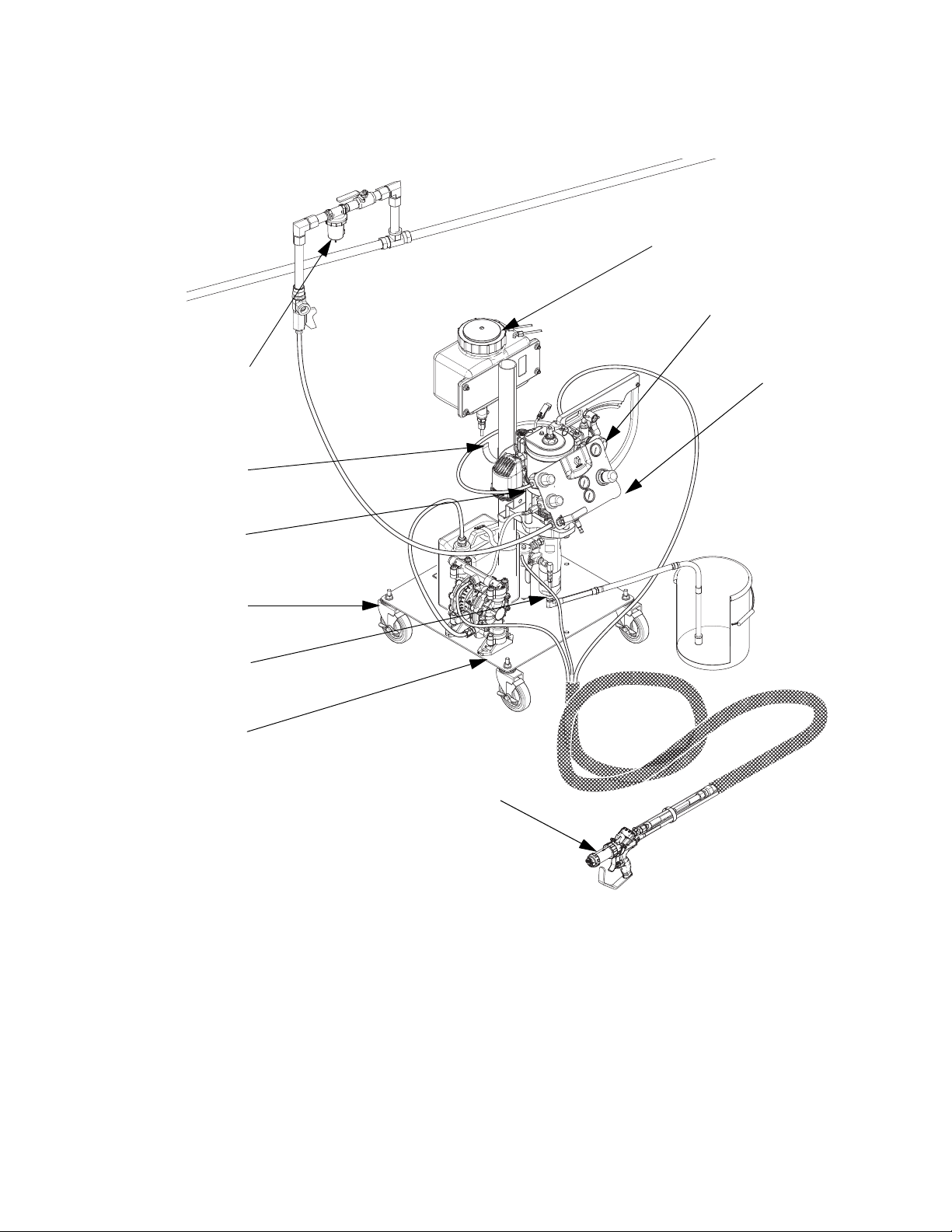
Component Identification
F
D
N
L
B
A
C
E
Cart system shown with solvent
flush diaphragm pump and external mix gel gun
H
WLF
M
Key:
ACart
BAir Motor
C Resin Displacement Pump
DCatalyst Pump
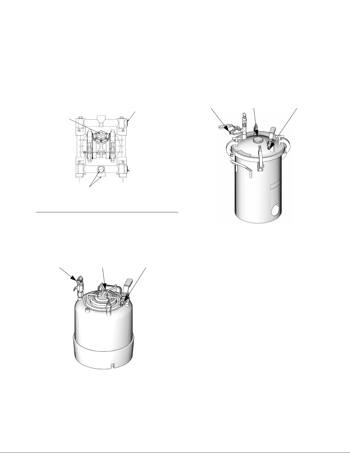
E Solvent Flush (Diaphragm Pump Option Shown,
Pressure Pot Options also available)*
F Catalyst Reservoir
G Boom (not shown)
* Internal mix systems only.
3A2012J 11
H Air Control Panel
J Heater (not shown)
K Grounding Wire (not shown)
L Hook support for resin hose coil
(25 ft and 35 ft hose bundles only)
M Spray gun
N Air/Water Separator (customer supplied)
Page 12
Component Identification
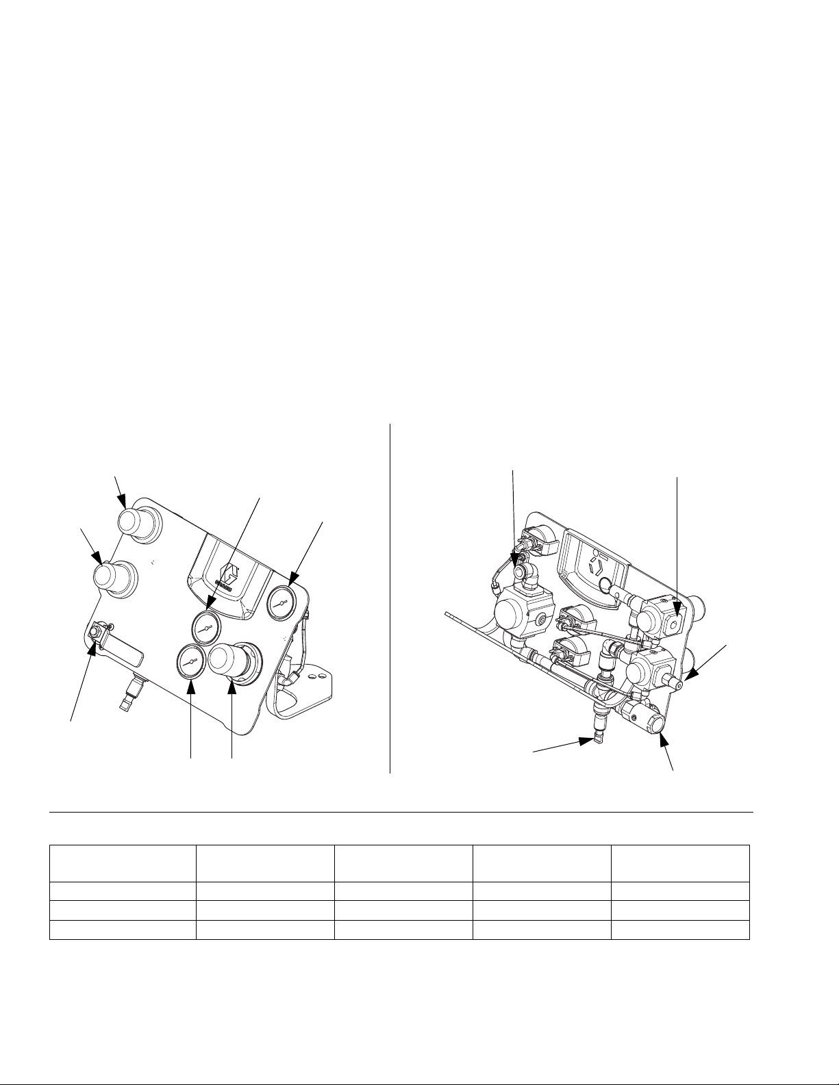
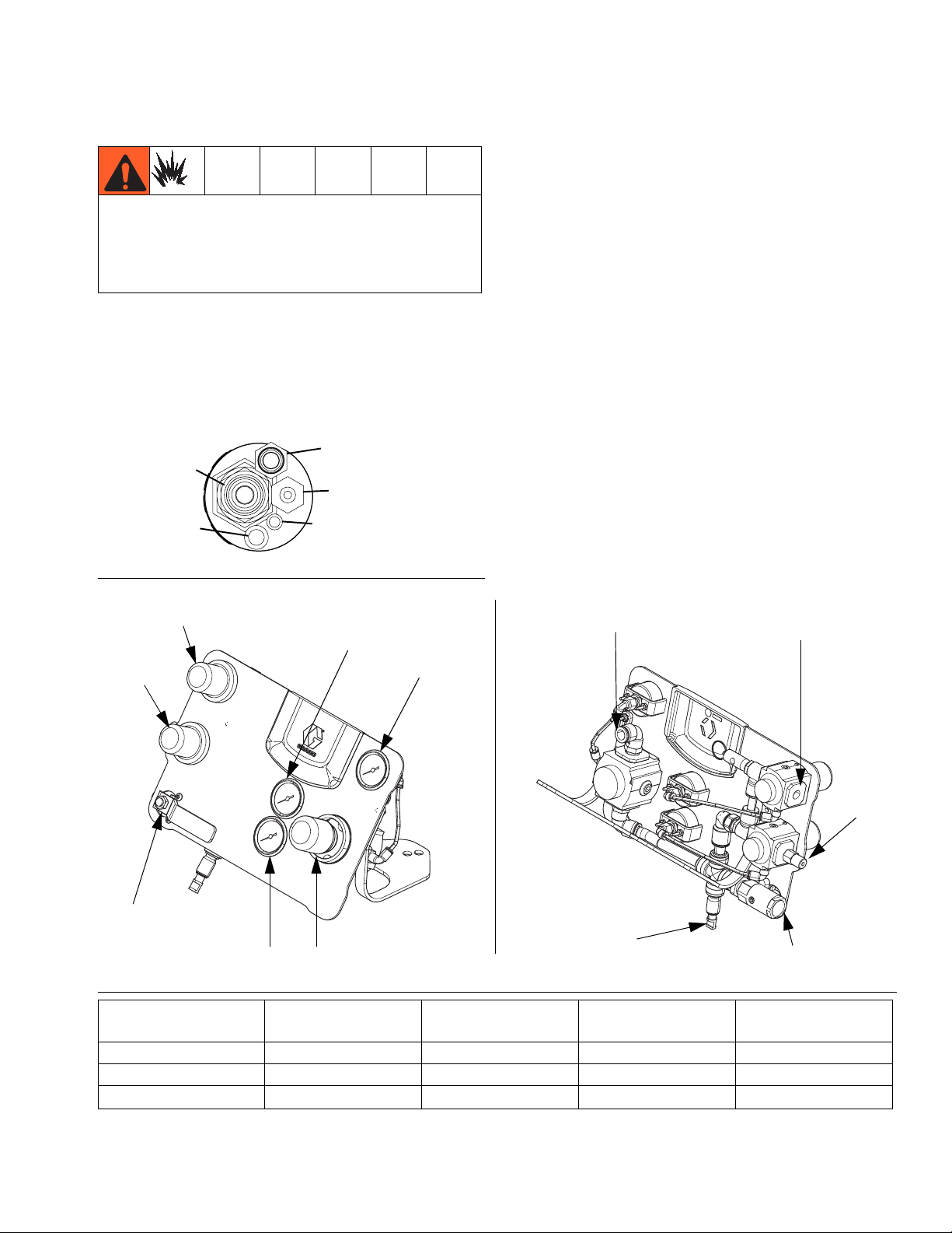
Air Control Panel
Air inlet (AA): from air line.
Air regulator 1 (AB): controls air to resin pump.
Air outlet 1 (AC): air line to resin pump.
Air pressure gauge 1 (AD): indicates air pressure to
resin pump.
Air regulator 2 (AE): for external mix guns only: con-
trols catalyst atomization air. For internal mix guns only:
controls solvent flush pressure.
Air outlet 2 (AF): for external mix guns only: catalyst air
line to spray gun. For internal mix guns only: to solvent
pump.
FRONT REAR
AH
AK
AE
AD
Air pressure gauge 2 (AG): indicates regulator 2 air
pressure.
Air regulator 3 (AH): controls Air Assist Containment
™
(AAC
) air to spray gun.
™
Air pressure gauge 3 (AK): indicates AAC air pressure.
Air outlet 3 (AM): AAC air line to spray gun.
Air outlet 4 (AN): Chop air supply to spray gun. This
outlet is plugged at the factory. Plug must be removed to
install chop air.
Air Shutoff valve (AP): shuts off air to entire system.
AC
AM
AP
ti21338a ti21339a
AN
ABAG
F
IG
. 1: Air Control Panel Components
Air Outlet Fitting
Details
Air Outlet 2 (AF) 3/8 tube 1/4 tube 3/8 tube 1/4 tube
Air Outlet 3 (AM) 1/4 tube 1/8 npt 3/8 tube 1/8 npt
Air Outlet 4 (AN)★ 1/2 tube 1/2 tube Plugged Plugged
Internal Chop External Chop Internal Gel External Gel
★ Includes a 1/2 to 3/8 reducer to adapt to older chop hose bundles
AF
AA
12 3A2012J
Page 13
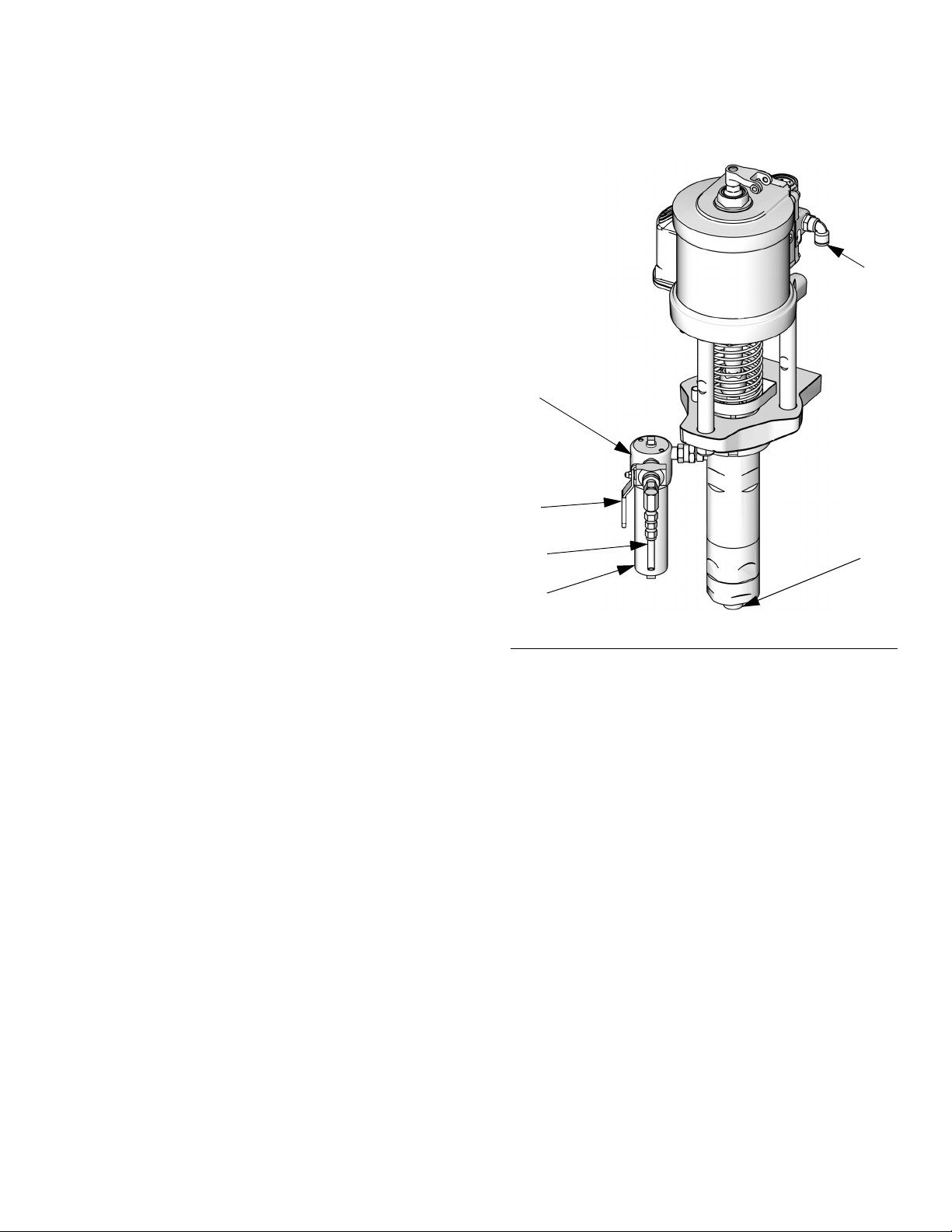
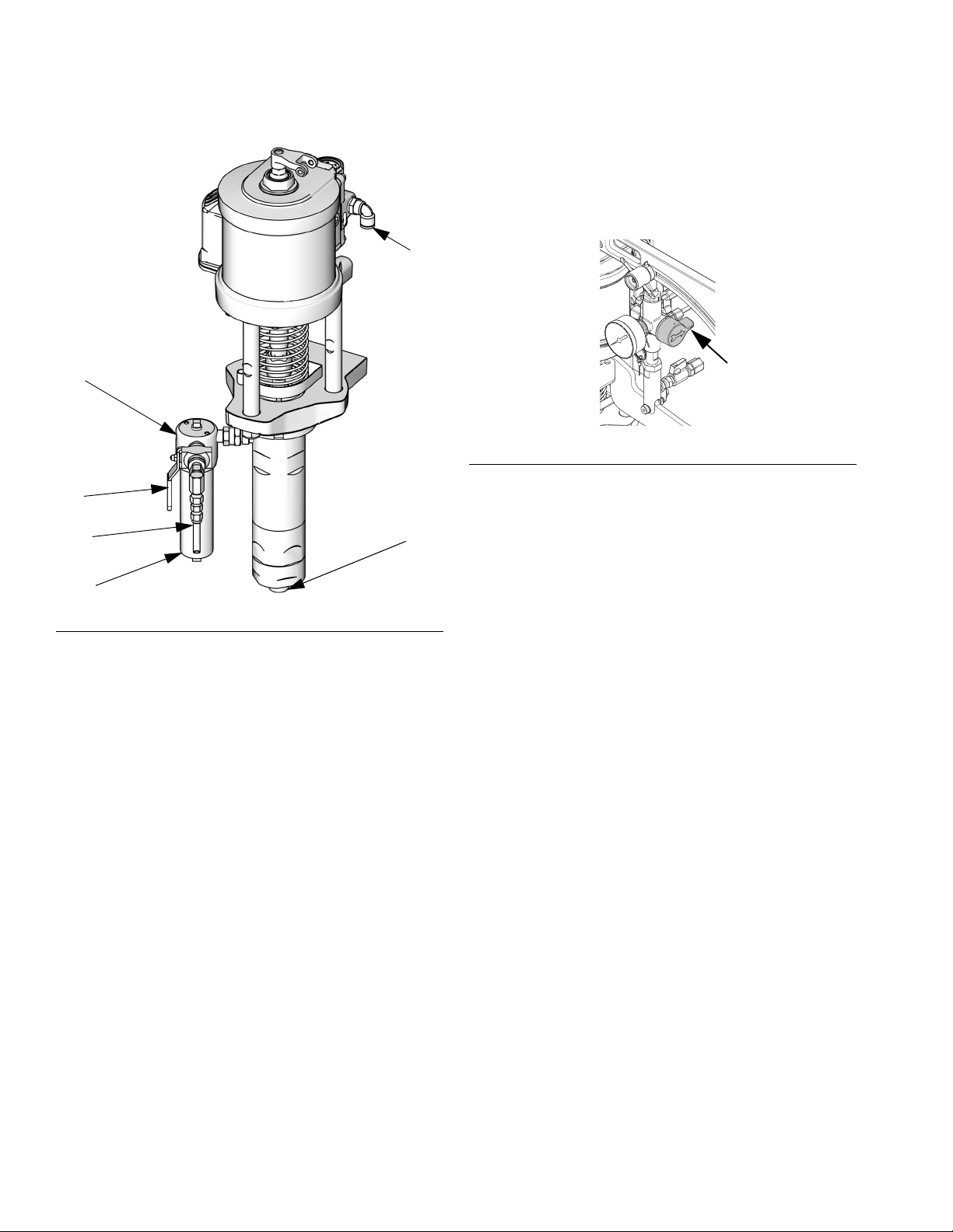
Air Motor and Resin Displacement Pump
The air motor powers the resin displacement pump
which supplies resin to the spray gun.
Air inlet (M): connect air hose to the air inlet.
Fluid filter (N): removes particles from the fluid.
Pressure relief/recirculation valve (P): relieves pres-
sure in the hose and gun.
Pressure relief/recirculation fluid outlet (P1): place
container below fluid outlet or connect fluid hose and
route back to the resin container, or install container
below the outlet
Pressurized fluid outlet on filter (R): connect fluid
hose to the 1/4 npt(f) fluid outlet reducer fitting supplied
with Graco hoses.
R
Component Identification
M
ti18499c
Fluid inlet (S): connect fluid suction hose to the
3/4 npt(m) fluid inlet.
DataTrak (T) (optional): electronic monitoring for material tracking, system diagnostics, and pump runaway
control. The DataTrak is located on the air control panel.
See the NXT Air Motor manual for details of the DataTrak controls and indicators.
P
P1
N
FIG. 2
S
3A2012J 13
Page 14
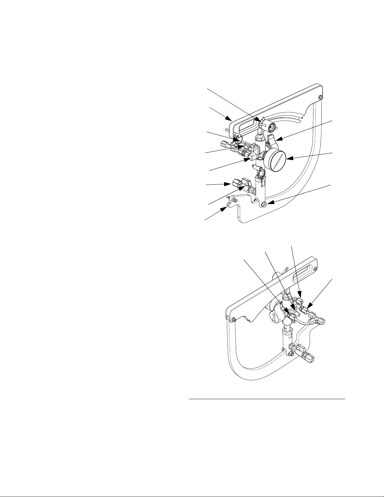
Component Identification
Catalyst Pump
The catalyst pump supplies catalyst to the spray gun.
Pump arm (U): controls catalyst flow.
Ratio adjustment knob (V1): use to lock/unlock pump
position and adjust the resin to catalyst ratio. It is easiest
to adjust the ratio when the pump is at the bottom of the
stroke.
V1
U
W
Pivot point (V2): when pump is moved to adjust ratio,
this point stays stationary.
High pressure relief valve (W): directs catalyst to gun
or back to tank to relieve pressure. It also automatically
relieves pressure if it exceeds normal working pressure.
Fluid pressure gauge (X): indicates catalyst fluid pressure.
Fluid inlet (Y): fluid inlet from the catalyst reservoir.
Fluid Inlet Ball Valve (Y2): controls flow of catalyst to
the catalyst pump.
Weep line (Z): In the event of a throat seal failure, the
fluid will flow into the weep line and back to the catalyst
reservoir.
Fluid outlet (Z1): fluid out to the gun.
Fluid recirculation/high pressure relief (Z2): fluid out-
let to the catalyst reservoir.
Low pressure relief valve (Z3): External mix systems
only. Directs catalyst to gun or back to tank to relieve
pressure.
Z2
Z
Z3
Y
Y2
U
Z2
ti21340a
Z1
X
V2
Z
Z3
ti21342a
F
IG
. 3: Catalyst Pump Components
14 3A2012J
Page 15
Solvent Flush Systems
Component Identification
Solvent Flush Diaphragm Pump
The solvent flush diaphragm pump provides solvent to
the gun to clear out mixed fluid and prevent it from curing in the gun. See the diaphragm pump manual listed
on page 3 for detailed component identification.
3/4 npt(f) Fluid
1/4 npt(f)
Outlet
Air Inlet
3/4 npt(f)
Fluid Outlet
3/4 npt(f) Fluid Outlet
ti9078a1
F
IG
. 4: Solvent Pump Components
Solvent Flush ASME Pressure Pot
Solvent Flush ASME and CE-Approved Pressure Pot
The pressure pot works by using the incoming air pressure to expel the solvent in the pot out of the fluid outlet.
See the ASME and CE-approved Pressure Pot manual
listed on page 3 for detailed component identification.
Air Inlet Fill Cap Fluid Outlet
ti18531a
The pressure pot works by using the incoming air pressure to expel the solvent in the pot out of the fluid outlet.
Verify supply tube is installed on fluid outlet port.
Air Inlet Fill Cap Fluid Outlet
ti18530a
3A2012J 15
Page 16
Setup
Setup
To avoid fire and explosion and electric shock, FRP
proportioners are not approved for use in hazardous
locations unless all accessories, all kits, and all wiring
meet local, state, and national codes. See Agency
Approvals on page 3.
FRP proportioners are not approved for use in hazardous locations unless all accessories, all kits, and all wiring meet local, state, and national codes. See Agency
Approvals on page 3.
This section provides instructions for basic system setup
of the FRP proportioner. See the separate component
manuals for detailed information.
Before Installation
• Have all system and component documentation
available during installation.
• If using a cart and boom system, ensure there is
enough space overhead and surrounding the proportioner for the boom and mast to fully extend.
• Place on a flat and level surface.
System Mounting (Wall Mount Systems Only)
To reduce the risk of skin injection injury, make sure
the system is depressurized before mounting any
pump assembly. See the Pressure Relief Procedure
and Shutdown on page 24.
For ease of operation and service, make sure the pump
air inlet, fluid inlet, and fluid outlet ports are easily
accessible. Mount the catalyst reservoir above the catalyst pump to enable gravity feed. Be sure the bracket is
level.
• See component manuals for specific data on compo-
nent requirements. Data presented here applies to
the FRP assemblies only.
• Be sure all accessories are adequately sized and
pressure-rated to meet system requirements. Accessories are available from Graco.
Component identification illustrations are only a guide
for selecting and installing system components and
accessories. Contact your Graco distributor for assistance in designing a system to suit your particular
needs.
Location Requirements
Refer to Dimensions, page 81, for mounting and clearance dimensions.
Cart Mount Systems
• Position the FRP proportioner so the air controls
and catalyst ratio adjustment arm are easily accessible.
ti18527d
NOTICE
To prevent damage to the system caused by the system falling off the wall, be sure the wall can support
the weight of the pump, bracket, hoses and accessories, and stress caused during pump operation.
1. For systems using pole mount:
a. Insert pole clamp bolts through catalyst reser-
voir mounting plate then each of the two upper
pole clamps, then install and tighten nuts to
secure mounting plate and clamps in place.
16 3A2012J
Page 17

NOTE: Catalyst reservoir outlet must be above the catalyst pump inlet fitting for true gravity feeding.
b. Insert pole clamp bolts through pumpline
mounting plate then each of the two lower pole
clamps, then install and tighten nuts to secure
mounting plate and clamps in place.
c. Use four bolts and washers to secure catalyst
reservoir to catalyst reservoir mounting plate.
d. Use four bolts and washers to secure pumpline
to pumpline mounting bracket.
2. For systems bolting directly to wall (not using a
pole):
a. Use four bolts, washers, and nuts to install cata-
lyst reservoir mounting bracket to wall.
Setup
b. Use four bolts, washers, and nuts to install cata-
lyst reservoir onto the catalyst reservoir mounting bracket.
c. Use four bolts, washers, and nuts to secure
pumpline mounting bracket to wall.
d. Use four bolts, washers, and nuts to secure
pumpline to pumpline mounting bracket.
3A2012J 17
Page 18
Setup
System Assembly
When the system is shipped from the factory some
items may be shipped loose. Perform the following
instructions to properly install each of the component
items.
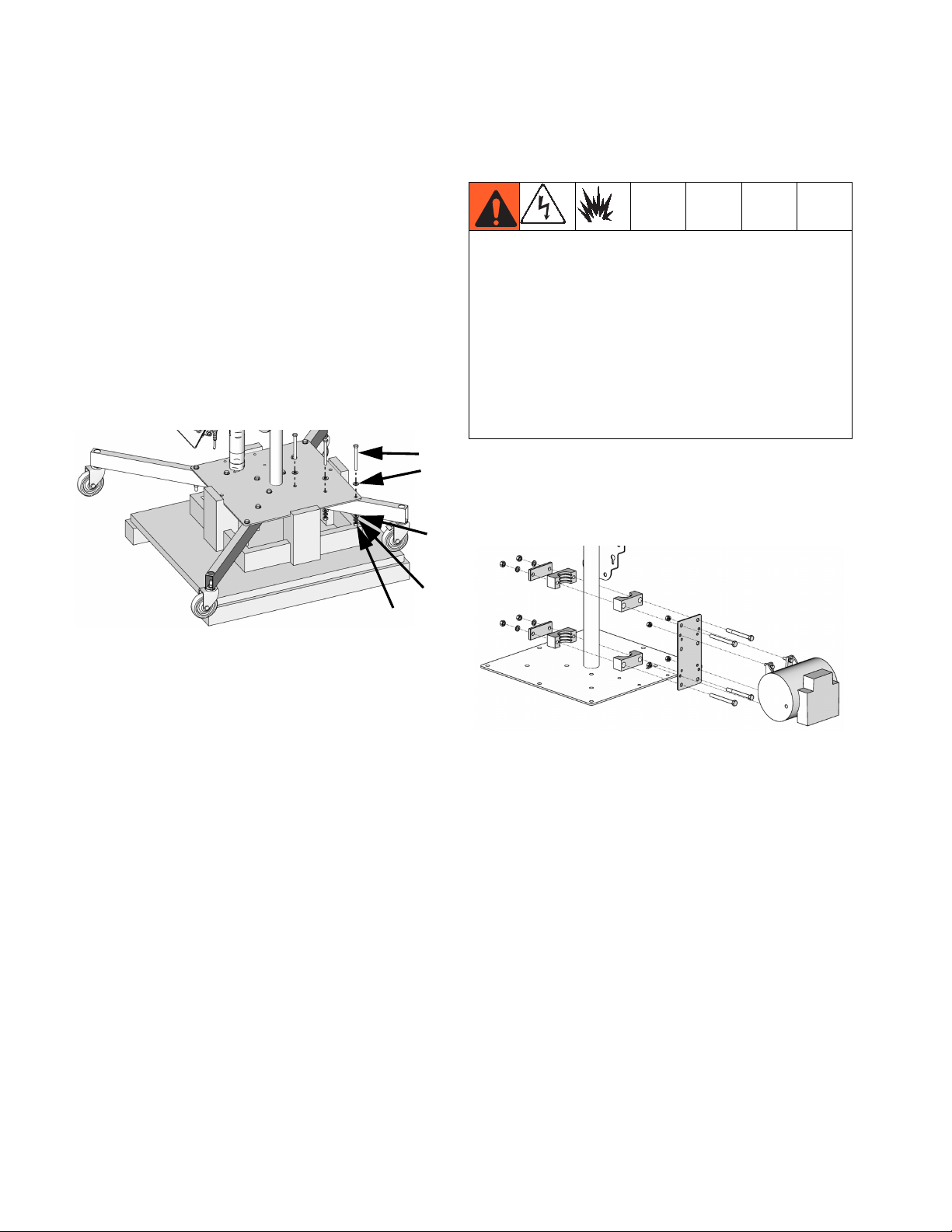
1. For cart and boom systems only, install legs:
a. With the system still on the pallet, use the sup-
plied hardware to install the legs onto the base
as shown below. The two longer legs should be
installed on the air control panel side of the
machine. The two non-locking casters should
be installed on the two longer legs.
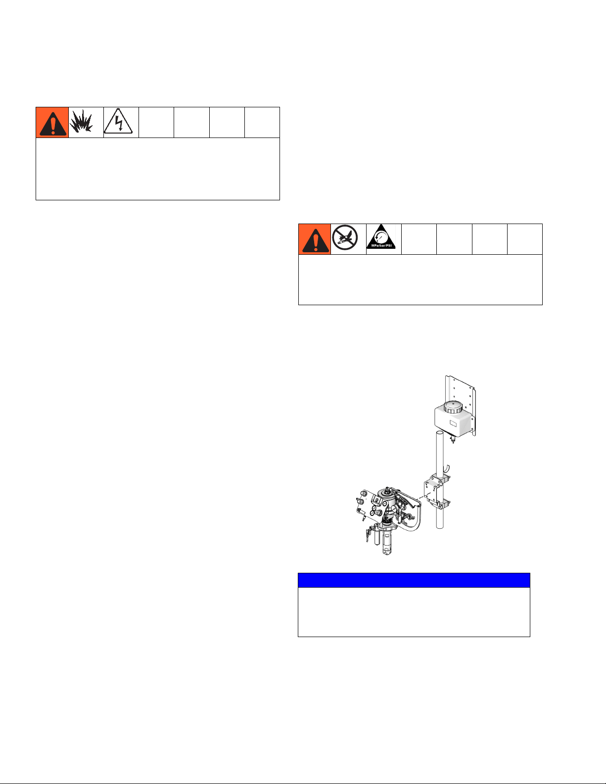
2. Connect heater (if ordered):
• Improperly installed or connected equipment may
create a hazardous condition that can cause fire,
explosion, or electric shock.
• Refer to heater manual listed on page 3 for
detailed instructions and warnings.
• You must have a qualified electrician connect
heater wiring. Ensure wiring and installation comply with local electrical codes for hazardous areas.
• Wiring, wiring connections, switches, and electrical
distribution panel must all meet flame-proof (explosion-proof) requirements.
a. Use supplied hardware to install heater onto
pole as shown below. Position the heater to
ease hose routing between pump and heater.
See Heater Kits manual for bolt hole patterns.
ti18523c
b. Use a forklift to raise the system off of the pallet,
remove the pallet, then place item directly on
the floor.
Viscon Heater Shown
ti18529b
b. Connect heater electrical connections. See
heater manual listed on page 3 for detailed
instructions.
18 3A2012J
Page 19
Setup
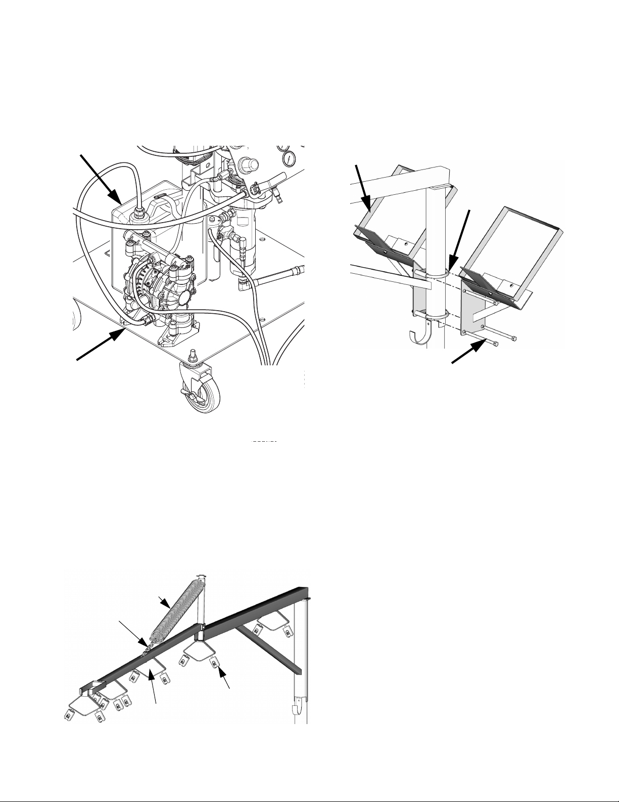
3. Install solvent flush diaphragm pump or pressure
pot (if ordered).
a. Use the supplied hardware to install the dia-
phragm pump or pressure pot onto the base of
the cart in the mounting holes provided.
6. Use the supplied hardware to install the roving box
bracket onto the pole. Install the top pole clamp
above the lower arm of the boom as shown below (if
ordered). If there is a second roving box, use long
hex screws as shown below to secure mounting
plate of second roving box to the mounting plate of
the first roving box.
ti18525b
Solvent Flush Diaphragm Pump shown
ti18455c
b. Use supplied hardware to install solvent supply
tank onto the base of the cart.
4. Install DataTrak Upgrade Kit (if ordered). Follow the
detailed instructions in DataTrak manual listed on
page 3.
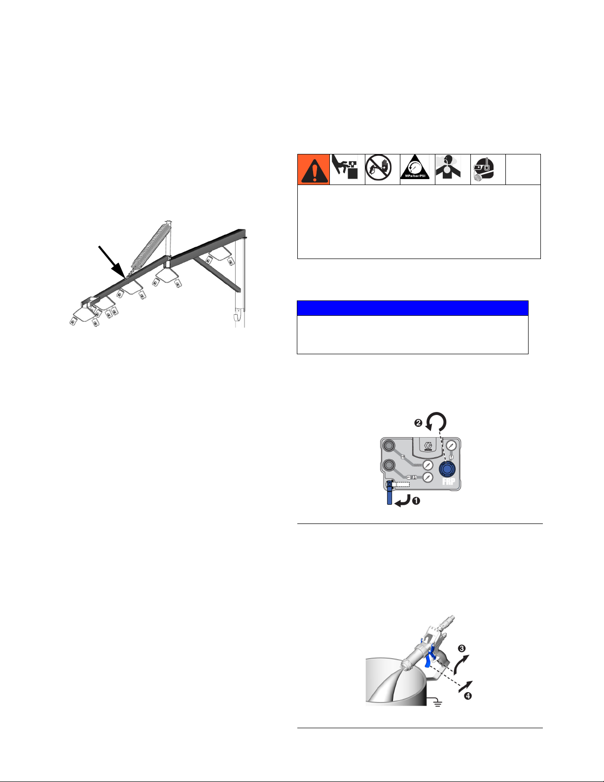
5. Assemble the boom as shown below then slide the
boom onto the system pole (if ordered).
Spring
Chain
Roving Guides
Deflector Plates
ti18532b
3A2012J 19
Page 20
Setup
Grounding
The equipment must be grounded to reduce the risk of
static sparking and electric shock. Electric or static
sparking can cause fumes to ignite or explode.
Improper grounding can cause electric shock.
Grounding provides an escape wire for the electric
current
General Grounding Guidelines
Pump: use ground wire and clamp (supplied). Connect
ground clamp to a true earth ground.
Air and fluid hoses: use only electrically conductive
hoses.
Spray gun: ground through connection to a properly
grounded fluid hose and pump.
Fluid supply container: follow local code.
FRP Proportioner Grounding
NOTE: All proportioners come with one grounding
clamp to ground the proportioner to a true earth ground.
All accessories for internal mix systems come with a
second grounding clamp to ground the solvent flush
system to the cart.
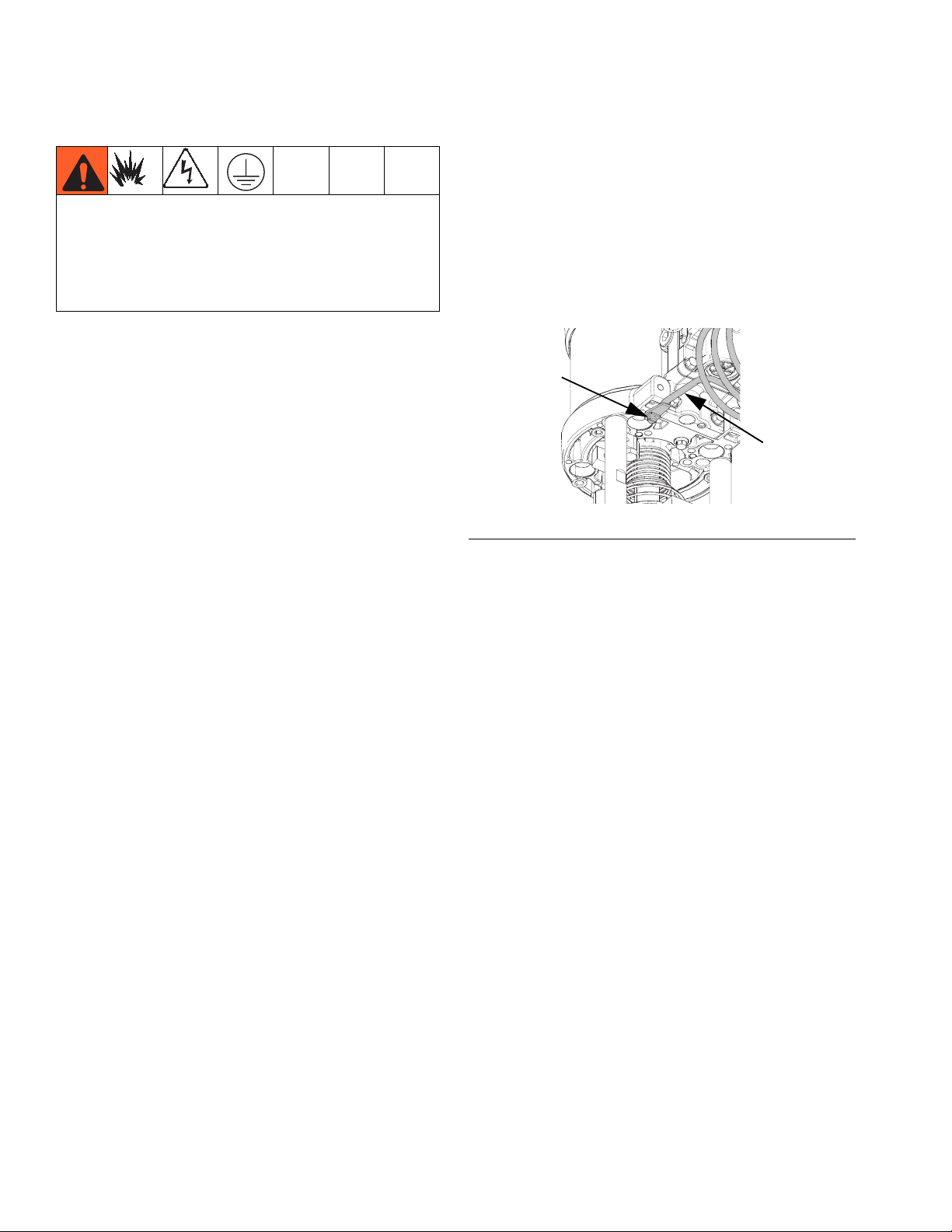
1. Verify that the ground screw is attached and tightened securely to the air motor. Connect the other
end of the ground wire to a true earth ground.
Ground
screw
Grounding
wire
ti18454a
FIG. 5: Ground Wire
Object being sprayed: follow local code.
Solvent pails used when flushing: follow local code.
Use only conductive metal pails, placed on a grounded
surface. Do not place the pail on a nonconductive surface, such as paper or cardboard, which interrupts
grounding continuity.
2. For internal mix systems only, ground the solvent
flush system.
a. For solvent flush diaphragm pumps only, con-
nect one end of the second grounding clamp to
the solvent pump grounding strip. See the diaphragm pump manual listed on page 3 for
grounding details.
b. Connect the other end of the grounding clamp
to the cart.
3. Use an ohmmeter to verify all components are
grounded to the earth ground.
4. If wall power is used to power the heater, ground
electrical connection according to local codes.
5. For cart proportioners: Connect the other end of the
second supplied grounding clamp to the cart.
For wall proportioners: Connect the other end of the
second supplied grounding clamp to a true earth
ground.
20 3A2012J
Page 21
Setup
Connect Fluid and Air Lines
Oil left in the system at the factory can react with catalyst and create a fire or explosion.
• Flush before first use.
• Do not add catalyst to the catalyst reservoir until
the system has been flushed.
NOTE: When connecting gun hose bundle, the whip
end connections in the bundle should be connected to
the gun and the non-whip end connections should be
connected to the proportioner. The whip end of the bundle is the end with more flexible lines. See gun manual
for hose bundle connection details and individual hose
identification.
Resin (Whip
Hose)
Air (Chop/
Internal Gel
AAC)
F
IG
. 6: Hose End Diagram
Solvent/ AAC Air
Catalyst
External Atomizing/
Internal Chop AAC Air
Air Connections
1. Verify air line from air outlet 1 (AC) on air control
panel is connected to air inlet (M) on air motor. See
F
IG
. 2 on page 13 and FIG. 7.
2. Connect AAC air line from gun hose bundle to air
outlet 3 (AM) on air control panel. See gun manual
for AAC air line identification.
3. External mix proportioners only: Connect the sup-
plied air tubing attached to air outlet 2 (AF) to atomized air line on gun.
Internal mix proportioners only: Connect the supplied air tubing attached to air outlet 2 (AF) to solvent pump air inlet. See F
IG
. 4 on page 15.
4. Chop systems only: Remove plug then connect the
chop air line (0.375 in. tube) in the gun hose bundle
to the chop air fitting (AN) on the air control panel.
5. Verify air shutoff valve (AP) is closed (handle is vertical) then connect the air supply line to the air
inlet (AA) on the air control panel.
AH
FRONT REAR
AC
AK
AE
AD
ti21338a ti21339a
AP
AN
ABAG
FIG. 7: Air Control Panel Components
Air Outlet Fitting
Details
Air Outlet 2 (AF) 3/8 tube 1/4 tube 3/8 tube 1/4 tube
Air Outlet 3 (AM) 1/4 tube 1/8 npt 3/8 tube 1/8 npt
Air Outlet 4 (AN)
★
Internal Chop External Chop Internal Gel External Gel
1/2 tube 1/2 tube Plugged Plugged
AM
AF
AA
★ Includes a 1/2 to 3/8 reducer to adapt to older chop hose bundles.
3A2012J 21
Page 22
Setup
Resin Pump and Optional Heater Connections
R
ti18499c
P
P1
Catalyst Pump Fluid Connections
NOTE: See F
IG
. 3 on page 14.
11. Verify the pressure relief/recirculation valve (W) is
set to pressure relief (knob is horizontal).
M
W
ti21343a
FIG. 9: Catalyst Pump Pressure Relief Valve
12. Connect the catalyst line from the gun hose bundle
to the catalyst outlet (Z1).
S
N
F
IG
. 8
6. Verify the pressure relief/recirculation valve (P) is
set to pressure relief.
7. Place a waste container below the fluid outlet then
remove the pump fluid inlet cap. Drain the test oil
then discard.
8. Connect resin suction hose to the resin pump
3/4 nptm fluid inlet (S). Place other end of suction
hose in resin container.
9. For non-heated systems only: Connect resin hose
from the gun hose bundle to the resin pump 1/4 nptf
fluid outlet (R). Reducer fitting comes with Graco
hose bundle.
For heated systems only: attach resin hose from the
gun hose bundle to the heater outlet. Verify fluid
hose connecting resin pump outlet to heater inlet is
installed and secure.
10. Connect resin recirculation hose to the pressure
relief/recirculation line (P1) and route to the resin
container.
22 3A2012J
Page 23

Solvent Flush Connections (if applicable)
NOTE: See Solvent Flush Systems component identi-
fication on page 15 for connection locations.
13. Connect solvent air line from air control panel to diaphragm pump or pressure pot air inlet.
14. Connect solvent suction tube from solvent supply
tank to solvent pump fluid inlet.
15. Connect solvent line from gun hose bundle to solvent fluid outlet.
Gun Connections
16. For 25 ft and 35 ft hose bundles only: Place the coil
of resin hose in the hose bundle on the hook support located on the pole. Secure with the supplied
rubber straps. The hook support should be inserted
through the center of the hose coil.
17. Secure all connections on the whip-end of the hose
bundle to the gun. See the gun manual listed on
page 3 for detailed instructions.
Setup
Flush Before First Use
Oil left in the system at the factory can react with catalyst and create a fire or explosion.
• Flush before first use.
• Do not add catalyst to the catalyst reservoir until
the system has been flushed.
Flush the system before first use to prevent contaminating the resin or catalyst. See page 30.
Fill Supply Tanks
Add fluid to the solvent flush supply tank (if applicable),
the catalyst supply reservoir, and the resin supply container.
3A2012J 23
Page 24
Operation
Operation
Trigger Lock
Always engage the trigger lock when you stop spraying
to prevent the gun from being triggered accidentally by
hand or if dropped or bumped.
Boom Operation
ti18532b
The height of the boom can be adjusted by adjusting
which link in the chain is secured to the boom arm.
Pressure Relief Procedure and Shutdown
The equipment stays pressurized until pressure is
manually relieved. To help prevent serious injury from
pressurized fluid such as skin injection, splashing fluid
and moving parts, follow the Pressure Relief Procedure when you stop spraying and before cleaning,
checking or servicing the equipment.
1. Close the main air supply ball valve.
NOTICE
Stop the pump at the bottom of its stroke to prevent
fluid from drying on the exposed displacement rod
and damaging the throat u-cup seals.
2. Turn the main air supply pressure regulator fully
counter-clockwise.
F
IG
. 10
3. Disengage the trigger lock on the gun. See F
4. With a grounded bucket below the gun, press the
gun against the side of the bucket and pull the trigger to relieve pressure in the fluid lines.
IG
. 11
F
24 3A2012J
IG
. 11.
Page 25
Operation
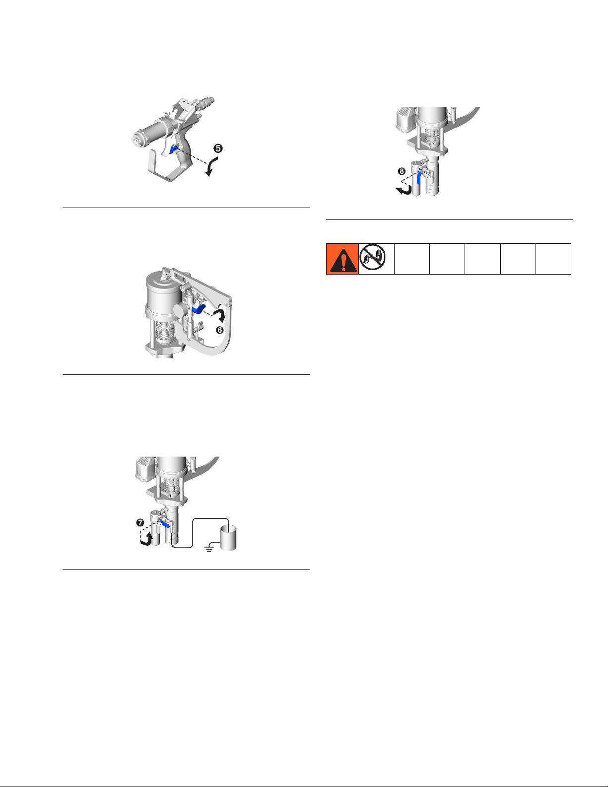
5. Engage trigger lock.
F
IG
. 12
6. Turn catalyst pump pressure relief/recirculation
valve to the pressure relief position.
8. After the pressure is fully relieved, turn the pressure
relief/recirculation valve to dispense position.
FIG. 15
9. If you suspect the spray tip, hose, or filter is completely clogged or that pressure has not been fully
relieved after following the previous steps, very
slowly loosen the hose end coupling and relieve
pressure gradually; then loosen completely.
IG
. 13
F
7. Verify that the resin pressure relief/recirculation fluid
line is routed to a grounded container, then turn the
pressure relief/recirculation valve to the pressure
relief position.
IG
. 14
F
10. See the gun manual listed on page 3 for shutdown
and maintenance procedures.
11. Perform the scheduled maintenance items listed on
page 38.
3A2012J 25
Page 26
Operation
Startup
NOTE: Do not exceed 20 psi (0.14 MPa, 1.4 bar) on the
material air pressure regulator until a steady material
flow has been established.
To avoid overpressurization, before turning on the
main air supply ensure all regulators are adjusted fully
counter-clockwise so they are set to zero pressure.
1. Verify wetcup is filled with Graco Throat Seal
™
Liquid (TSL
2. Ensure main air line is connected to the air control
panel air inlet (AA).
3. For internal mix proportioners only, check solvent
line:
a. Verify gun is ready to begin operation. See gun
manual.
).
5. As desired, perform Prime, Flush, or Spray proce-
dures beginning on page 27. Make sure to flush the
system before first use to flush out oil used to test
the equipment at the factory.
b. Turn shutoff valve (AP) on the air control panel
to the open position.
c. Open the air valve on the solvent pump and
adjust the solvent pressure to 90 psi (0.63 MPa,
6.3 bar).
d. Open the ball valve on the solvent pump.
e. Open solvent knob on the gun to verify that sol-
vent will flow out of the front of the gun through
the dispense tip, then close the valve.
Oil left in the system at the factory can react with catalyst and create a fire or explosion.
• Flush before first use.
• Do not add catalyst to the catalyst reservoir until
the system has been flushed.
4. If this is the first startup of the machine, perform the
Flush procedure on page 30.
26 3A2012J
Page 27

Prime
Perform this procedure upon initial system setup, whenever hoses are disconnected, if the supply hose is
removed from the supply container, or if either pump is
run dry. If done properly, this will prime the lines with
fluid and/or remove any air bubbles from the fluid lines.
NOTE: If using an NXT air motor with DataTrak, see
DataTrak Operation, page 33.
NOTE: For systems with DataTrak: When priming
pumps, it is normal to get cavitation or pump runaway
Operation
Oil left in the system at the factory can react with catalyst and create a fire or explosion.
• Flush before first use.
• Do not add catalyst to the catalyst reservoir until
the system has been flushed.
2. Verify the resin suction tube is in the resin supply
container. Verify catalyst pump inlet tube is properly
connected to the catalyst reservoir and catalyst
pump fluid inlet ball valve is open. Verify both the
resin supply container and catalyst supply reservoir
have adequate fluid levels.
alarms. Clear alarms , and press again as
necessary. These alarms prevent excessive pump
speeds, which will damage pump packings.
1. To enable the user to better see fluid exiting each
fluid port, the front end of the RS gun can be
removed. This step is optional but can be very useful:
a. Follow Pressure Relief Procedure and Shut-
down on page 24.
b. Remove the RS gun front end. See RS gun
manual list on page 3 if desired.
Never allow the pump to run dry of the fluid being
pumped. A dry pump quickly accelerates to a high
speed, possibly damaging itself and causing overpressurization and equipment rupture. If your pump accelerates quickly or is running too fast, stop it immediately
and check the fluid supply. If the supply container is
empty and air has been pumped into the lines, refill the
container and prime the pump and the lines with fluid,
or flush and leave it filled with a compatible solvent. Be
sure to eliminate all air from the fluid system.
3. Units with runaway protection only: enable the
prime/flush function by pushing the prime/flush button on the DataTrak. This prevents the DataTrak
from stopping the pump if it detects a high cycle
rate.
4. Verify the pressure relief/recirculation valves on the
catalyst pump is set to the pressure relief/recirculation position.
F
IG
. 16
3A2012J 27
Page 28

Operation
5. Verify the pressure relief/recirculation valves on the
resin pump is set to the pressure relief/recirculation
position.
IG
. 17
F
6. Turn the main air supply pressure regulator fully
counter-clockwise to relieve pressure and set to
zero pressure. See F
IG
. 18.
7. Turn the main air supply ball valve to the open position. See F
IG
. 18.
8. Slowly turn the main air supply pressure regulator
clockwise until the pump starts to move and will
change-over by itself. Never turn past 20 psi
(0.14 MPa, 1.4 bar). See F
IG
. 18.
10. Turn the catalyst pump pressure relief/recirculation
valve to the dispense position.
FIG. 20
11. Disengage the trigger lock on the gun. See F
IG
. 21.
To reduce the risk of exposure to the dispensed material mist, when performing the following step use a pail
lid with a hole to dispense through. Seal around hole
and gun with a rag to prevent splash back.
To reduce the risk of skin injection, be careful to keep
fingers away from front of gun.
F
IG
. 18
9. When material begins to flow and all air bubbles
have been expelled, turn the resin pump pressure
relief/recirculation valve to the dispense position.
IG
. 19
F
To reduce the risk of fire and explosion, use a
grounded pail.
12. Purge air from resin and catalyst hoses: with a
grounded bucket below the gun, press the gun
against the side of the bucket and pull the trigger to
dispense. Continue dispensing until air-free fluid is
dispensed from both ports on the front of the gun.
See F
IG
. 21. The pump air pressure may need to
increase slightly until the material begins to flow.
F
IG
. 21
28 3A2012J
Page 29

13. Turn the main air supply ball valve to the closed
position.
F
IG
. 22
14. Turn the catalyst pump pressure relief/recirculation
valve to the pressure relief position. This will relieve
any built up pressure.
Operation
F
IG
. 23
15. Verify that the resin pressure relief/recirculation fluid
line is routed to a grounded container, then turn the
pressure relief/recirculation valve to the pressure
relief position.
IG
. 24
F
16. Units with runaway protection only: disable the
prime/flush function by pushing the prime/flush button on the DataTrak.
17. Engage gun trigger lock.
18. If the front end of the gun was removed, apply
grease to o-rings and front of gun to prevent material from curing or sticking to it, then install gun front
end.
3A2012J 29
Page 30

Operation
Flush
Oil left in the system at the factory can react with catalyst and create a fire or explosion.
• Flush before first use.
• Do not add catalyst to the catalyst reservoir until
the system has been flushed.
To reduce the risk of fire and explosion and skin injection injury, only use a solvent compatible with the system wetted parts, the resin, and the catalyst.
Flush the system:
• Before first use
• When changing fluids
• Before repairing equipment
• Before fluid dries or settles out in a dormant pump
(check the pot life of catalyzed fluids)
• Before storing the pump.
Flush at the lowest pressure possible. Flush with a fluid
that is compatible with the fluid you are pumping and
with the wetted parts in your system. Check with your
fluid manufacturer or supplier for recommended flushing
fluids and flushing frequency.
NOTE: Always flush catalyst pump separately by hand
(remove pin from upper control arm and hand pump).
1. Remove all fluid inlet, recirculation, and weep lines
from the catalyst reservoir and insert in a container
filled with a compatible solvent.
2. Remove the resin pump fluid supply and recirculation lines from the resin supply container and insert
in a container filled with a compatible solvent.
NOTICE
To prevent accidentally mixing resin and catalyst in
the solvent container, there must be two solvent
containers used, with the resin pump fluid lines
inserted in one and the catalyst pump fluid lines
inserted in the other.
3. With the fluid lines in the two separate solvent containers, perform the Prime procedure at the lowest
pressure possible. While performing this procedure,
leave the fluid supply, recirculation, and supply lines
in the solvent containers.
30 3A2012J
Page 31

Operation
Spray
NOTE: If using an NXT air motor with DataTrak, see
DataTrak Operation, page 33, for instructions on using
the DataTrak counter/totalizer.
Prior to production use, spray onto a clean piece of
paper until all system settings are adjusted to optimize
the spray pattern.
Perform this full procedure whenever the gun has been
unused for an extended period of time, such as overnight. After performing this full procedure, spraying can
be performed intermittently as desired by simply pulling
the trigger and utilizing the trigger lock to prevent accidental triggering.
1. If this is the first time starting up the system, if fluid
lines have been disconnected, if the fluid supply line
has been removed from the supply container, or if
either pump has been run dry, perform Prime pro-
cedure on page 27.
2. Turn the main air supply ball valve to the closed
position.
3. Turn the main air supply pressure regulator fully
counterclockwise.
4. Turn the resin pump pressure relief/recirculation
valve to the dispense position.
FIG. 26
5. Turn the catalyst pump pressure relief/recirculation
valve to the dispense position. See F
IG
. 27.
6. Bring catalyst pump fluid outlet line to dispensing
pressure (see F
IG
. 27):
a. Remove pin connecting upper catalyst pump
arm to air motor rod then manually stroke the
pump until the catalyst pressure gauge shows:
External mix systems: 30-40 psi
(0.21-0.28 MPa, 2.1-2.8 bar).
Internal mix systems: 300-400 psi (2.1-2.8 MPa,
21-28 bar).
b. Insert pin to connect upper catalyst pump arm
to air motor.
F
IG
. 27
FIG. 25
3A2012J 31
Page 32

Operation
7. Turn the main air supply ball valve to the open position. See F
IG
. 28.
8. Slowly turn the main air supply pressure regulator
clockwise until the main air supply pressure gauge
IG
reads the desired pressure. See F
F
IG
. 28
9. Disengage trigger lock on the gun. See F
10. Pull trigger to begin dispensing. See F
. 28.
IG
IG
. 29.
. 29.
NOTE: In the following step, to minimize catalyst overspray, use as little catalyst atomization air pressure as
possible to achieve desired spray pattern. See the spray
gun manual for instructions.
11. If the spray pattern has not already been set up to
perform as desired, see RS gun manual for detailed
instructions for how to optimize the spray pattern,
including adjusting the AAC air pressure at the system or gun, and adjusting the catalyst atomization
air.
no air too little air
correct amount
of air
FIG. 30: AAC Air Adjustment
12. After all pressure adjustments are made, spray a
final test shot on a clean piece of paper. This shot
should be approximately 5 ft long. Check desired
gel times and uniformity of curing.
F
IG
. 29
13. For internal mix proportioners only: When finished
spraying engage trigger lock then point the gun into
a waste container and use the solvent knob on the
gun to move solvent through the gun to flush the
gun.
14. For external mix proportioners only: When finished
spraying, squirt the tip of the gun with solvent to
remove any mixed material.
15. If necessary, use a brush to remove cured material
from front of the gun.
16. If finished spraying for an extended period of time:
Follow Pressure Relief Procedure and Shutdown
on page 24.
32 3A2012J
Page 33

DataTrak Operation
Operation
For DataTrak installation instructions, see NXT Air
motor for FRP manual.
NOTICE
To prevent damage to the soft key buttons, do not
press the buttons with sharp objects such as pens,
plastic cards, or fingernails.
Controls and Indicators
NOTE: See FIG. 31. The display (Y) will turn off after 1 minute of inactivity in Run mode or 3 minutes in Setup mode.
Press any key to wake up the display. DataTrak will continue to count cycles when display is off.
Run Mode
GT
CF; See Details at right.
RK
CF
BT
PF
TI8622b
CC
*CB
CD
TI11883a
RK
FIG. 31. DataTrak Controls and Indicators
Key:
CA Runaway Limit, in cycles per minute (user settable;
00=OFF)
CB * Lower Displacement (user settable)
CC Flow Rate Units (user settable to gpm [US],
gpm [Imperial], oz/min [US], oz/min [Imperial], l/min, or
cc/min)
CD LED (fault indicator when lit)
CE Diagnostic Reference Card (see Table 1, page 37)
CF Display
/min,
Setup Mode
RT
UT
DT
ST
PF
CA
PF Prime/Flush Key (Enables Prime/Flush mode. While in
Prime/Flush mode, runaway protection is disabled and
the batch totalizer (BT) will not count.)
RK Reset Key (Resets faults. Press and hold for 3 seconds to
clear the batch totalizer.)
CF Cycle/Flow Rate
BT Batch Totalizer
GT Grand Totalizer
RT Runaway Toggle (enable/disable)
UT E1 Error Option (enable/disable)
DT E2 Error Option (enable/disable)
ST E5 Error Option (enable/disable)
TI8623b
3A2012J 33
Page 34

Operation
* 13:1 pump setting is 80cc (for 2 in stroke).
17:1 pump setting is 60cc (for 2 in. stroke).
34 3A2012J
Page 35

Setup Mode
Operation
1. See FIG. 31. Press and hold for 5 seconds until
Setup menu appears.
2. To enter settings for runaway, lower size, and flow
rate units, and to enable runaway, E1, E2, and E5
error options, press to change the value, then
to save the value and move the cursor to the
next data field. See page for a description of E1, E2,
and E5 error codes.
Run Mode
Runaway Monitor
1. See F
2. Runaway Screens 1 and 2: To reset the runaway
AP
IG
. 31. If pump runaway occurs, the runaway
solenoid will actuate, stopping the pump. The LED
(CD) will flash and the display (CF) will indicate a
runaway condition (see Table 1). The display will
cycle through six instruction screens.
solenoid, close the master air valve (AP). Wait for
air to completely bleed off the air motor.
NOTE: When runaway, E1, E2, and E5 error options are
enabled, a ✓ will appear on the setup screen. See F
IG
31.
3. Move the cursor to the E5 error enable option field,
then press once more to exit Setup mode.
J
ti11902a
FIG. 32. Solenoid Release Button
.
3. Runaway Screens 3 and 4: After the air is bled off,
push the solenoid release button (J) down to reset
the air valve. The button will pop back up when the
air valve is repressurized.
4. Runaway Screens 5 and 6: Press to clear the
diagnostic code and reset the runaway solenoid.
5. Open master air valve (AP) to restart pump.
NOTE: To disable runaway monitoring, go to setup
mode and set runaway value (CA) to 0 (zero) or disable
(RT) (see F
IG
. 31).
3A2012J 35
Page 36

Operation
Prime/Flush
1. See F
IG
. 31. To enter Prime/Flush mode, press any
key to wake up the display, then press . The
Prime/Flush symbol will appear in the display and
the LED will flash .
2. While in Prime/Flush mode, runaway protection is
disabled and the batch totalizer (BT) will not count.
The grand totalizer (GT) continues to count.
1. To exit Prime/Flush mode, press any key to wake
up the display, then press . The Prime/Flush
symbol will disappear from the display and the LED
will stop flashing.
Counter/Totalizer
See F
IG
. 31. The last digit of the batch totalizer (BT) represents tenths of gallons or liters. To reset the totalizer,
press any key to wake up the display, then press and
hold for 3 seconds.
Display
See F
IG
. 31. The display (CF) will turn off after 1 minute
of inactivity in Run mode or 3 minutes in Setup mode.
Press any key to wake up the display.
NOTE: DataTrak will continue to count cycles when display is off.
NOTE: The display (CF) may turn off if a high-level
static discharge is applied to the DataTrak. Press any
key to wake up the display.
Diagnostics
DataTrak can diagnose several problems with the
pump. When the monitor detects a problem, the LED
(CD, See F
IG
. 31) will flash and a diagnostic code will
appear on the display. See Table 1.
To acknowledge the diagnosis and return to the normal
operating screen, press once to wake up the display, and once more to clear the diagnostic code screen
• If AC is set to gallons or ounces, BT and GT display gallons.
• If AC is set to liters or cc, BT and GT display
liters.
• If AC is set to cycles, BT and GT display cycles.
Press to toggle between flow rate units and cycles.
A letter under the BT display indicates that both BT and
GT are displaying gallons (g) or liters (l). No letter
means both BT and GT are displaying cycles.
36 3A2012J
Page 37

Table 1: Diagnostic Codes
Symbol Code Code Name Diagnosis Cause
Runaway
(DataTrak only)
E-1 Diving Up Leak during upstroke. Worn piston valve or packings.
E-2 Diving Down Leak during downstroke. Worn intake valve.
Pump running faster than set
runaway limit.
•
Increased air pressure.
•
Increased fluid output.
•
Exhausted fluid supply.
Operation
E-3 Low Battery Battery voltage too low to stop
runaway.
E-4 Service
Component 1
(units with
runaway
protection only)
E-4 Disconnected
Solenoid
(units with
runaway
protection only)
E-5 Service
Component 2
E-6 Blown Fuse Fuse is blown. Replace fuse;
Problem with stopping runaway.
Solenoid is disconnected.
Solenoid is not engaging piston
cup.
Problem with sensing valve
movement.
see page 38.
Low battery. Replace battery;
see page 38.
•
Damaged solenoid.
•
Damaged valve carriage.
•
Runaway (RT, FIG. 31) protection may be enabled with
pump that is not equipped
with a runaway solenoid
valve. Enter setup screen
and disable runaway protection.
•
Solenoid unplugged.
•
Damaged solenoid wires.
•
Bracket and solenoid not
tight against air valve housing.
•
Sensors unplugged.
•
Sensors mounted incorrectly.
•
Damaged sensors.
•
Damaged valve carriage.
•
Faulty solenoid or solenoid
wiring.
•
Extreme temperatures
(above 140°F [60°C]).
•
Runaway (RT, FIG. 31) protection may be enabled with
pump that is not equipped
with a runaway solenoid
valve. Enter setup screen
and disable runaway protection.
3A2012J 37
Page 38

Operation
Replace DataTrak Battery or Fuse
4. Remove two screws on back of module to access
battery.
The battery and fuse must be replaced in a
non-hazardous location.
Use only the following approved replacement batteries. Use of an unapproved battery will void Graco’s
warranty and FM and Ex approvals.
• Ultralife lithium # U9VL
• Duracell alkaline # MN1604
• Energizer alkaline # 522
• Varta alkaline # 4922
Use only a Graco-approved replacement fuse. Order
Part 24C580.
Replace Battery
1. Unscrew cable from the back of the reed switch
assembly. See F
2. Remove the cable from the two cable clips.
IG
. 33.
5. Disconnect the used battery and replace with an
approved battery. See F
IG
. 34.
Replace Fuse
1. Remove the screw, metal strap, and plastic holder.
2. Pull the fuse away from the board.
3. Replace with a new fuse.
Solenoid Cable
Connection
Fuse
Sensor Cable
Connection
ti11992a
F
IG
. 33. Disconnect DataTrak
3. Remove DataTrak module from bracket. Take module and attached cable to a non-hazardous location.
Battery
ti11994a
FIG. 34. DataTrak Battery and Fuse Location
38 3A2012J
Page 39

Maintenance
Task Schedule
Maintenance
Inspect pump wetcup
and fill with TSL and
remove any particles or
residue
Remove resin pump
outlet filter and flush
debris
Inspect hoses for wear
or damage and replace
immediately if found
Remove catalyst
reservoir filter and
clean with solvent
Replace catalyst
reservoir filter
Flush system
Daily
Daily
Weekly
As needed
As needed
As needed
Components
See component manuals listed on page 3 for maintenance schedules and procedures for each component.
3A2012J 39
Page 40

Troubleshooting
Troubleshooting
Follow Pressure Relief Procedure and Shutdown
on page 24 before checking or servicing the equipment.
Problems
Try the recommended solutions in the order given for
each problem, to avoid unnecessary repairs.
Catalyst Pump
See Catalyst Slave Pumps parts illustration on page 66 for parts identification.
Problem Cause Solution
Pressure loss on up stroke. Worn transfer housing seal. Replace transfer housing seal.
Worn transfer housing seat. Replace transfer housing.
Pressure loss on up stroke and down
stroke.
Pressure not building on up stroke. Damaged transfer housing seat. Replace transfer housing.
Pressure not building on down stroke. Scratched inlet valve. Replace inlet valve.
Leakage from cartridge housing. Loose cartridge housing. Tighten cartridge housing.
Pressure being relieved through relief
valve or check valve at a low pressure.
Pump will not prime. Fluid inlet ball valve is closed. Open fluid inlet ball valve.
Excessive weepage Missing snap-on seal retainer Remove cartridge and install
Worn weep seals. Replace weep cartridge.
Blow off valve spring is wearing out. Replace blow off valve.
Loose fittings on spray gun and/or hoses. Tighten fittings on spray gun and hoses.
Scratched piston rod. Replace piston rod.
Loose bearing. Tighten bearing.
Relief valve or check valve has a weak
spring.
Worn or damaged snap-on seal retainer Remove and replace
Replace relief valve or check valve.
Resin Pump
See Resin Pumplines on page 61 for parts identification.
Problem Cause Solution
Does not operate. Valve closed or clogged. Clear air line; increase air supply. Check that
valves are open.
Fluid hose or gun obstructed. Clean hose or gun.*
Dried fluid on displacement rod. Clean rod; always stop pump at bottom of stroke;
keep wet-cup filled with Throat Seal Liquid (TSL).
Air motor parts dirty, worn, or damaged. Clean or repair air motor. See air motor manual.
Runaway error on DataTrak tripped (if DataTrak
installed)
Stall on bottom of
stroke.
40 3A2012J
Runaway solenoid actuated. (if DataTrak installed) Enable runaway protection, if disabled, then see
See DataTrak Operation-Runaway Monitor,
page 35.
Runaway, page 35, to reset the runaway solenoid.
Page 41

Troubleshooting
Problem Cause Solution
Output low on both
strokes.
Pump output low on
only one stroke.
No output. Improperly installed ball check valves. Check and repair.
Pump operates erratically.
Erratic accelerated
speed.
Runs sluggishly. Possible icing. See air motor manual for instructions.
Cycles or fails to hold
pressure at stall.
Air bubbles in fluid. Loose suction line. Tighten. Use compatible liquid thread sealant or
Poor finish or irregular
spray pattern.
Difficulty priming Inlet ball stuck to seat Tap pump with hammer to dislodge.
Air line restricted or air supply inadequate. Valves
closed or clogged.
Fluid hose/gun obstructed. Clear hose or gun*.
Air motor icing. See air motor manual for instructions.
Exhausted fluid supply. Refill and prime pump.
Worn piston packings. Replace.
Open or worn intake valve. Clear or service intake valve.
Held open or worn ball check valves. Check and repair.
Worn piston packings. Replace.
Exhausted fluid supply. Refill and reprime pump.
Held open or worn ball check valves. Check and repair.
Worn piston packing. Replace.
Suction tube too restrictive, causing pump to cavitate
Fluid supply exhausted, clogged suction. Refill supply and prime pump. Clean suction tube.
High viscosity fluid. Reduce viscosity; increase fluid temperature,
Open or worn piston valve or seal. Clear piston valve; replace seal.
Open or worn intake valve. Clear or service intake valve.
Filler material clumping causing extra friction on
rods and seals.
Worn check valves or seals. Service lower. See lower manual for instructions.
Incorrect fluid pressure at gun. See gun manual; read fluid manufacturer’s recom-
Fluid is too thin or too thick. Adjust fluid viscosity; read fluid manufacturer’s rec-
Dirty, worn, or damaged spray gun. Service spray gun. See spray gun manual.
Suction hose/strainer too restrictive or clogged Clean inlet strainer, shorten hose length and/or
Clear air line; increase air supply. Check that
valves are open.
Use larger diameter tube
reduce flow rate by using smaller tip.
Flush pump and replace packings.
PTFE tape on connections.
mendations.
ommendations.
Remove inlet ball, flush dried material, re-install
inlet ball.
increase hose diameter (especially cold or viscous
material.
* To determine if fluid hose or gun is obstructed, follow Pressure Relief Procedure and Shutdown, page 24. Dis-
connect fluid hose and place a container at pump fluid outlet to catch any fluid. Turn on air power just enough to
start pump. If pump starts, the obstruction is in fluid hose or gun.
** The runaway solenoid can still be actuated if the Runaway Error is not displayed. Also, disabling the runaway
monitor will not retract the solenoid.
3A2012J 41
Page 42

Repair
Repair
• To reduce the risk of fire and explosion, repair procedures must be performed in a non-hazardous
location. Move system to non-hazardous location
before performing any repair procedure.
•Follow Pressure Relief Procedure and Shut-
down on page 24 before checking or servicing the
equipment.
• To prevent contact with fluids, flush the system
prior to disassembling any components that contain catalyst or resin.
5. Hold the flats of the air
motor piston rod with a
wrench. Use another
wrench to loosen the
coupling nut.
6. Lower the coupling nut
(A) enough to remove
the coupling collars
(B), and then remove
the coupling nut (A).
Use a magnet to aid removing the two collars (B).
ti12815a
General Information
• Reference numbers and letters in parentheses in
the text refer to the callouts in the figures and the
parts drawing.
• Always use Genuine Graco Parts and Accessories,
available from your Graco distributor. If you supply
your own accessories, be sure they are adequately
sized, pressure rated, and made of materials compatible with your system.
Disconnect the Displacement Pump
See manual 3A2313 for displacement pump service and
parts information.
A
ti12812a
7. Pull up on TSL reservoir (C) to remove.
8. Use a hammer and
brass rod to loosen the
jam nut. Unscrew the
jam nut as far as possible.
9. Protect hands with a
rag then unscrew the
displacement pump by
hand and place on
work bench.
B
C
ti12813a
ti12816a
1. Flush the pump, see page 30.
2. Stop the pump in the middle of the stroke.
3. Relieve the pressure, see page 24.
4. Disconnect the air supply and fluid hoses.
42 3A2012J
Threads are very sharp. Use a rag to protect hands
when hand turning or carrying the pump.
10. See displacement pump manual 3A2313 for pump
service procedures and parts information.
Page 43

Repair
Reconnect the Displacement Pump
1. Disconnect air supply from air motor.
2. Hand-turn the displacement pump into the adapter
plate.
3. Install coupler spring guard and TSL reservoir.
4. Hold the air motor piston rod up with one hand. With
your other hand, put the coupling nut (A) on the displacement rod.
5. Put the coupling
collars (B) into
the coupling nut
(A) so large
flanges point
upward.
6. Gently let the air
motor piston rod
drop onto the displacement rod.
Hand tighten the
coupling nut (A).
B
A
ti12817a
8. Align fluid outlet as shown and tighten the jam nut.
9. Align the TSL reservoir (C) and push it down into
place.
10. Hold the flats of the motor rod with a wrench. Use
another wrench to tighten the coupling nut (A).
Torque to 75-80 ft-lb (102-108 N•m).
11. Reconnect air supply to motor.
7. Screw the displacement pump into the adapter
plate (D) until the cylinder top is flush with the top of
the adapter plate.
Cylinder, not
wet cup, should
be flush with
plate.
D
ti12814a
F
IG
. 35. Align cylinder and adapter plate.
3A2012J 43
Page 44

Repair
Disconnect the Air Motor
See manual 3A2315 for air motor service and parts
information. See F
1. Relieve the pressure, see page 24.
2. Disconnect main air supply line from the inlet on the
air control panel (AE).
3. Disconnect grounding wire.
4. Disconnect items from the air motor:
a. Note location of all air hoses connected to air
motor then disconnect the hoses from the air
motor.
b. Remove top pin (AA) connecting upper catalyst
pump arm to air motor, then remove bolts (AB)
connecting lower catalyst pump arm to air motor
then remove catalyst pump and control arms
assembly (AC).
c. Remove two bolts (AD) securing air control
panel to air motor then remove air control
panel (AE).
5. Hold the flats of the air motor piston rod with a
wrench. Use another wrench to loosen the coupling
nut (A). Lower the coupling nut (A) enough to
remove the coupling collars (B), then remove the
coupling nut (A).
IG
. 36 on page 45.
8. Lift up on the air motor to remove it. The tie
rods (AJ) will remain attached to the air motor.
9. Use a socket on the flats of the tie rods (AJ) to
remove them from the bottom of the air motor.
10. See air motor manual 3A2315 for repair procedures
and parts information.
Reconnect the Air Motor
See FIG. 36 on page 45.
1. Screw the tie rods (AJ) into the bottom of the air
motor. With a wrench on the flats of the tie rods,
torque to 50-55 ft-lb (68-75 N•m).
2. Align the tie rods (AF) with the holes in the pump
adapter. Carefully lower the air motor into place.
3. Attach the tie rod nuts (AF) to tie rods then torque to
50-60 ft-lb (68-81 N•m).
4. Install and tighten the screws (AG) that secure air
motor to mounting bracket (AH).
5. Install coupler spring guard and TSL reservoir.
6. With coupling
collars (B) in
place, hand
tighten the coupling nut, then
torque to
75-80 ft-lb
(102-108 N•m).
7. Connect the air
and fluid hoses.
B
A
ti12817a
A
B
The equipment must be grounded to reduce the risk of
C
static sparking and electric shock. Electric or static
sparking can cause fumes to ignite or explode.
Improper grounding can cause electric shock.
Grounding provides an escape wire for the electric
current
ti12812a
6. Use a 23 mm socket to remove the tie rod nuts (AF).
ti12813a
8. Attached grounding wire to true earth ground.
7. Use a 13 mm socket to loosen the top two
screws (AG) that secure air motor to mounting
bracket (AH).
44 3A2012J
Page 45

Repair
AJ
AA
AH
AC
AG
AK
FIG. 36
AB
AF
AE
AD
ti18456c
3A2012J 45
Page 46

Repair
Replace Pumpline
This procedure is only needed if the entire pumpline will
be replaced. If just installing repair parts in the air motor
and/or displacement pump, see Disconnect the Dis-
placement Pump on page 42, Disconnect the Air
Motor on page 44, displacement pump manual 3A2313,
and air motor manual 3A2315.
1. Flush the pump, see page 30.
2. Relieve the pressure, see page 24.
3. Disconnect main air line from air panel (AE).
4. Disconnect items from the air motor, see F
page 45:
a. Note location of all air hoses connected to air
motor then disconnect the hoses from the air
motor.
b. Remove top pin (AA) connecting upper catalyst
pump arm to air motor, then remove bolts (AB)
connecting lower catalyst pump arm to air motor
then remove catalyst pump and control arms
assembly (AC).
c. Remove two bolts (AD) securing air control
panel to air motor then remove air control
panel (AE).
5. Disconnect the air and fluid hoses.
6. Disconnect the ground wire.
7. Use a socket to loosen the two screws (AG) connecting the air motor to the mounting bracket (AH).
IG
. 36 on
8. Use a socket to remove the two screws (AK) securing the displacement pump to the mounting bracket.
9. Lift up on the pumpline to slide pumpline out of
bracket.
10. Reassembly is reverse of assembly.
46 3A2012J
Page 47

Repair
Repair Catalyst Pump
See FIG. 37 on page 49 for reference numbers.
Remove Catalyst Pump from System
1. Flush the pump, see page 30.
2. Relieve the pressure, see page 24.
3. Close catalyst supply ball valve and disconnect fluid
lines.
4. Remove top pivot knob securing catalyst pump to
upper control arm.
5. Remove bolt securing catalyst pump to lower control arm then remove catalyst pump.
Disassemble Catalyst Pump
6. Pull pivot knob (929) out to fully extend the slave
pump rod (910).
7. Remove quick release pin (908) from slave pump
housing (901).
8. Holding the slave pump housing (901) stationary
with one hand, use a crescent wrench on the flats of
the slave pump cylinder (918) to loosen then
remove the cylinder and foot valve (922) assembly.
9. Place the slave pump housing (901) in a vise. Use
the flats provided by the quick-release pin (908)
hole.
14. Use crescent wrench to loosen then remove the
bearing (902b) and felt wiper (902d) assembly.
15. Remove seal (902f) from inside of cartridge (902a).
16. Remove o-ring (902g).
17. Install new seal (902f) into bottom of the
cartridge (902a) with the u-cup opening facing into
the pump.
18. Install seal (902f) with onto weep seal installation
tool 16N967 with u-cup opening facing into the
pump then use tool to install seal into inside of
cartridge (902a).
19. Install felt wiper (902d) and bearing (902b) into
cartridge (902a). Tighten to 20-60 in-lb
(2.3-6.8 N•m).
20. Install o-ring (902g).
21. Install snap-on seal (902e).
22. Lubricate the piston rod.
23. With bullet tool 16D007 installed on the piston rod,
install cartridge assembly (902) onto the rod.
24. Remove the bullet tool.
25. Use one wrench on the transfer housing (914) and
another on the transfer housing cap (917) to break
them loose from each other then remove the cap
from the housing.
10. Use a crescent wrench on the flats of the
cartridge (902) to loosen then remove the cartridge
and piston rod (910) assembly.
Repair Throat and Piston Seals
11. Use a wrench on the flats of the piston rod (910) to
hold it stationary while using a second wrench on
the flats of the transfer housing (914) to loosen then
remove the housing and cap (917) assembly.
12. Install bullet tool 16D007 on the piston rod (910)
then pull the rod (910) out of the cartridge (902).
NOTICE
Bullet tool 16D007 must be used or damage to the
seals will result when removing or installing items
onto the rod.
13. Remove snap-on seal retainer (902e) then remove
seal (902f).
3A2012J 47
26. Remove seal (915) and guide (916) from transfer
housing.
27. Remove spring (911), valve (912), and o-ring (913)
from transfer housing.
28. Remove o-ring (913) from the valve (912).
29. Install new o-ring (913) on new valve (912).
Page 48

Repair
30. Hold spring (911) upright, place valve (912) on top
of spring, slide transfer housing (914) upside down
over the spring then flip upright.
31. Install transfer housing (914) onto piston rod (910).
Use flats on rod and transfer housing to torque
transfer housing against the piston rod to 30-50 in-lb
(3.4-5.6 N•m).
32. Slide the cartridge (902) down against the transfer
housing (914).
33. Install u-cup (915) onto transfer housing with u-cup
opening facing up towards the rod.
34. Install guide (916) onto transfer housing.
35. Install transfer housing cap (917) onto transfer
housing. Use flats to torque to 30-50 in-lb
(3.4-5.6 N•m).
Repair Foot Valve
36. Use wrench to loosen lock nut (921) then remove
cylinder (918) from foot valve (922).
37. Remove ball (925) from foot valve.
38. Remove backup o-ring (920) and o-ring (919) from
both ends of the cylinder (918).
39. Remove ball seat (923). Tool 24N253 can be used
to aid ball seat removal.
40. Place new ball seat onto seat installation tool
16N996 with lip opening facing in towards tool.
Assemble Catalyst Pump
46. Verify cartridge (902) is pressed against the transfer
housing (914).
47. Lubricate the o-ring (902g) on the cartridge.
48. Apply thread sealant to the threads of the
cartridge (902a).
49. With the slave pump housing (901) in a vise, carefully thread the cartridge (902) into the housing.
Torque the cartridge to 240 in-lb (27.1 N•m).
50. Lubricate the o-rings (919, 920) on the
cylinder (918).
51. Hand-thread the cylinder (918) into the slave pump
housing (901) all the way until the cylinder bottoms
out. Rotate the cylinder counterclockwise less than
1/2 turn until the flat on the cylinder is parallel with
the quick-release pin hole then insert the
quick-release pin (908).
52. With the quick-release pin in place, rotate the foot
valve counterclockwise less than one full-turn so
that it is facing directly backwards relative to the
pressure gauge.
53. Hold the foot valve in position and tighten the lock
nut (921) against the foot valve to 225-275 in-lb
(25.4-31.1 N•m).
54. Push the piston rod (908) down into the slave pump
housing (901).
41. Place tool into foot valve then tap with a hammer
until ball seat is properly seated then remove tool.
42. Install new backup o-ring (920) and o-ring (919)
onto both ends of the cylinder (918). Make sure to
install the o-rings in the correct position, with the
backup o-rings towards the center of the cylinder.
43. Lubricate the backup o-rings (920) and
o-rings (919).
44. Install ball into foot valve.
45. Thread cross-cut end of cylinder into foot valve by
hand until it bottoms out but do not tighten the jam
nut.
48 3A2012J
Page 49

Repair
929 927
5
946
1
935
1
909
6
907
1
6
6
909
919
920
5
921
Internal Mix shown
922
924
11
External Mix Only
6
908
947
11
928
5
902d
926
12
910
902
901
932
2
1 4
8
12
1
947
1
902b
902f
902a
13
902g
902f
903
51
903a
3
ti19060a
902e
14
911
912
913
914
8
945
1
ti21344a1
1
903b
3
1
Apply pipe sealant to threads.
2
Apply thread locker to mating surfaces or threads.
3
Apply grease to mating surfaces or threads.
4
Torque to 240 in-lb (27.1 N•m).
5
Torque to 225-275 in-lb (25.4-31.1 N•m).
6
Loop large end of lanyard over gauge prior to
assembling gauge. Attach small end of lanyard to
1
split ring on pin.
7
Note orientation of u-cup.
8
Torque to 30-50 in-lb (3.4-5.6 N•m).
9
Clean cylinder inner diameter with soft cloth or
equivalent, prior to assembly.
10
Hand tighten cylinder (918) and bottom out to
housing (901). Back-off cylinder (918) less than 1/2
turn. Assembly pin (908).
11
Press fit bearings.
12
Torque piston rod (910) to top link (926) to
80-100 in-lb (9.0-11.3 N•m).
13
Torque to 20 - 60 in-lb (2.3-6.8 N•m).
14
Snap 902e onto 902a.
915
916
917
918
7
8
9
903c
10
920
919
925
923
940
930
1
11
924
932
1
1
946
939
934
1
938
939
947
937
1
1
FIG. 37: Catalyst Pump Details
3A2012J 49
Page 50

System Parts
System Parts
Systems
121
107
4
106
5
4
152
111
105
7
110
8
113
104
109
1
103
114,115,116
108
104
102
108
113
8
122
ti19056b
1
Loosen grounding lug locknut and washer, insert
grounding wire into slot in lug and tighten locknut
securely.
4
Apply grease to outer diameter, not to the threads.
5
Torque to 45-55 ft-lb (61-75 N•m).
7
Connect tubing to catalyst pump.
8
Torque to 20-30 ft-lb (27-41 N•m).
50 3A2012J
Page 51

System Parts
Systems
See Models table on page 4 for detailed descriptions of each system number to identify which system number you
have. To make reading the table below easier, find your system number in the left-most column then place a
straight-edge (such as the edge of a blank piece of paper) below that row of the table. If necessary, use a second
straight-edge vertically in the table to identify the part number of each item used in the system.
Ref. Part Description
102 16N918 WALL OR POLE MOUNT KIT
(No Cart)
--- CART, for use with boom 11 1111
--- CART 11 11111
103 W13DFCPUMP, FRP, 13:1 1111 1111111
W17CFS PUMP, FRP, 17:1 1 1
104 111799SCREW, cap, hex head 6666666666666
105 16P125 HARNESS, slave linkage 1 111111111111
106 119999BOLT, shoulder 1111111111111
107 24M092PIN, quick release, 1.5 x 0.25 1111111111111
108 16N741PUMP, slave, external mix 1 1 1 1111111
16N740 PUMP, slave, internal mix 1 1 1
109 120476BOLT, shoulder, 5/16 1111111111111
110 111040NUT, lock, insert, nylock, 5/16 1111111111111
111 16M564 LABEL, ratio, 13:1, FRP 1 1 1 1 1 1 1 1111
16M565 LABEL, ratio, 17:1, FRP 1 1
112◆ 16N761BOOM KIT 11 1111
113 16U750PANEL, air control 1111111111111
114 113093FITTING, connector, 1/4 nptf 1111111111111
115 114109 FITTING, elbow, male, swivel 1
121141 FITTING, elbow, swivel, 3/8t 1/4mnpt 2 2
16D939FITTING, nipple, reducing 1 1 1 1111111
116 114109FITTING, elbow, male, swivel 1 1 1 1111111
121141 FITTING, elbow, male, swivel 1
118 --- TUBING, nylon, round 3 3 3
119◆ 238909WIRE, grounding 1111111111111
121 --- TUBE, nylon, round 3333333333333
122 124071PLUG, fitting, push-to-connect 11 111111111
123◆ 16M588 HOSE, bundle, 25 ft external gel 1 1 1
16M587 HOSE, bundle, 25 ft internal gel 1 1
16M586 HOSE, bundle, 25 ft chop 1 1
16M591 HOSE, bundle, 35 ft external gel 1 1
16M590 HOSE, bundle, 35 ft internal gel
16M589 HOSE, bundle, 35 ft chop
16M585 HOSE, bundle, 50 ft external gel 1 1
16M584 HOSE, bundle, 50 ft internal gel
16M583 HOSE, bundle, 50 ft chop
124◆ 258970 GUN, external mix, chop, with cutter 1
258840 GUN, external mix, gel 1 1 1 1 1 1 1
258971 GUN, internal mix, chop, with cutter 1
258853 GUN, internal, gel 1 1
125◆ 16M736SUPPLY HOSE, 55 gallon 1111111111111
126◆ 16M810KIT, FRP 1111111111111
151◆ ▲ 16D136 LABEL, warnings 1 111111111111
16R001
16R002
16R003
16R004
16R005
16R006
16R009
16R012
16R015
16R018
16R021
16R024
16R027
152 24M692SPACER, ball joint 1111111111111
◆ Item not shown.
▲ Replacement Danger and Warning labels, tags and cards are available at no cost.
3A2012J 51
Page 52

System Parts
Ref. Part Description
102 16N918 WALL OR POLE MOUNT KIT
16R030
16R033
16R036
16R039
16R044
16R047
16R050
16R053
16R056
16R059
16R062
16R065
16R068
16R071
1111 1111
16R074
16R079
16R082
16R085
16R088
16R091
16R094
(No Cart)
--- CART, for use with boom 1 1 1 1 1 1 1
--- CART 111 1111
103 W13DFC PUMP, FRP, 13:1 1111111111111111111111
W17CFS PUMP, FRP, 17:1
104 111799 SCREW, cap, hex head 6 6 6 6666666666666666666
105 16P125 HARNESS, slave linkage 1111111111111111111111
106 119999 BOLT, shoulder 1111111111111111111111
107 24M092 PIN, quick release, 1.5 x 0.25 1111111111111111111111
108 16N741 PUMP, slave, external mix 1111 1111111
16N740 PUMP, slave, internal mix 11111111111
109 120476 BOLT, shoulder, 5/16 1111111111111111111111
110 111040 NUT, lock, insert, nylock, 5/16 1111111111111111111111
111 16M564 LABEL, ratio, 13:1, FRP 1111111111111111111111
16M565 LABEL, ratio, 17:1, FRP
112◆ 16N761 BOOM KIT 1 1 1 1 1 1 1
113 16U750 PANEL, air control 1111111111111111111111
114 113093 FITTING, connector, 1/4 nptf 1111111111111111111111
115 114109 FITTING, elbow, male, swivel
121141 FITTING, elbow, swivel, 3/8t
22222222222
1/4mnpt
16D939 FITTING, nipple, reducing 1111 1111111
116
114109 FITTING, elbow, male, swivel 1111 1111111
121141 FITTING, elbow, male, swivel
118 --- TUBING, nylon, round 33333333333
119◆ 238909 WIRE, grounding 1111111111111111111111
121 --- TUBE, nylon, round 3333333333333333333333
122 124071 PLUG, fitting, push-to-connect 111111111111111
123◆ 16M588 HOSE, bundle, 25 ft external gel 1
16M587 HOSE, bundle, 25 ft internal gel 1 1
16M586 HOSE, bundle, 25 ft chop 1
16M591 HOSE, bundle, 35 ft external gel 1
16M590 HOSE, bundle, 35 ft internal gel 1 1 1
16M589 HOSE, bundle, 35 ft chop 1 1
16M585 HOSE, bundle, 50 ft external gel 1
16M584 HOSE, bundle, 50 ft internal gel 1 1 1
16M583 HOSE, bundle, 50 ft chop 1 1
124◆ 258970 GUN, external mix, chop, with cutter 1 1 1 1 1
258840 GUN, external mix, gel 1 1 1
258971 GUN, internal mix, chop, with cutter
258853 GUN, internal, gel 1 1 1 1 1 1 1 1
125◆ 16M736 SUPPLY HOSE, 55 gallon 1111111111111111111111
126◆ 16M810 KIT, FRP 1111111111111111111111
151◆ ▲ 16D136 LABEL, warnings 1111111111111111111111
152 24M692 SPACER, ball joint 1111111111111111111111
◆ Item not shown.
16R097
▲ Replacement Danger and Warning labels, tags and
cards are available at no cost.
52 3A2012J
Page 53

System Parts
Ref. Part Description
102 16N918 WALL OR POLE MOUNT KIT
16R100
16R103
16R106
16R109
16R114
16R117
16R120
16R123
16R126
16R129
16R132
16R135
16R138
16R141
1111 1111
16R144
16R149
16R152
16R155
16R158
16R161
16R164
(No Cart)
--- CART, for use with boom 111 1111
--- CART 1111 111
103 W13DFC PUMP, FRP, 13:1 111111111111111
W17CFS PUMP, FRP, 17:1 1111111
104 111799 SCREW, cap, hex head 6666666666666666666666
105 16P125 HARNESS, slave linkage 1111111111111111111111
106 119999 BOLT, shoulder 1111111111111111111111
107 24M092 PIN, quick release, 1.5 x 0.25 1111111111111111111111
108 16N741 PUMP, slave, external mix 1111 1111111
16N740 PUMP, slave, internal mix 11111111111
109 120476 BOLT, shoulder, 5/16 1111111111111111111111
110 111040 NUT, lock, insert, nylock, 5/16 1111111111111111111111
111 16M564 LABEL, ratio, 13:1, FRP 111111111111111
16M565 LABEL, ratio, 17:1, FRP 1111111
112◆ 16N761 BOOM KIT 111 1111
113 16U750 PANEL, air control 1111111111111111111111
114 113093 FITTING, connector, 1/4 nptf 1111111111111111111111
115 114109 FITTING, elbow, male, swivel 11111111111
121141 FITTING, elbow, swivel, 3/8t
1/4mnpt
16D939 FITTING, nipple, reducing 1111 1111111
116
114109 FITTING, elbow, male, swivel 1111 1111111
121141 FITTING, elbow, male, swivel 11111111111
118 --- TUBING, nylon, round 33333333333
119◆ 238909 WIRE, grounding 1111111111111111111111
121 --- TUBE, nylon, round 3333333333333333333333
122 124071 PLUG, fitting, push-to-connect 1111111
123◆ 16M588 HOSE, bundle, 25 ft external gel 1
16M587 HOSE, bundle, 25 ft internal gel
16M586 HOSE, bundle, 25 ft chop 1 1 1
16M591 HOSE, bundle, 35 ft external gel 1 1
16M590 HOSE, bundle, 35 ft internal gel
16M589 HOSE, bundle, 35 ft chop 1 1 1 1
16M585 HOSE, bundle, 50 ft external gel 1 1
16M584 HOSE, bundle, 50 ft internal gel
16M583 HOSE, bundle, 50 ft chop 1 1 1 1
124◆ 258970 GUN, external mix, chop, with cutter 1 1 1
258840 GUN, external mix, gel 1 1 1 1 1
258971 GUN, internal mix, chop, with cutter 1 1 1 1 1 1 1 1
258853 GUN, internal, gel
125◆ 16M736 SUPPLY HOSE, 55 gallon 1111111111111111111111
126◆ 16M810 KIT, FRP 1111111111111111111111
151◆ ▲ 16D136 LABEL, warnings 1111111111111111111111
152 24M692 SPACER, ball joint 1111111111111111111111
◆ Item not shown.
16R167
▲ Replacement Danger and Warning labels, tags and
cards are available at no cost.
3A2012J 53
Page 54

System Parts
Ref. Part Description
102 16N918 WALL OR POLE MOUNT KIT
16R170
16R173
16R176
16R179
16R184
16R187
16R190
16R193
16R196
16R199
16R202
16R205
16R208
16R211
1111 1111
16R214
(No Cart)
--- CART, for use with boom
--- CART
111
1111
103 W13DFC PUMP, FRP, 13:1
W17CFS PUMP, FRP, 17:1
104 111799 SCREW, cap, hex head
105 16P125 HARNESS, slave linkage
106 119999 BOLT, shoulder
107 24M092 PIN, quick release, 1.5 x 0.25
108 16N741 PUMP, slave, external mix
16N740 PUMP, slave, internal mix
109 120476 BOLT, shoulder, 5/16
110 111040 NUT, lock, insert, nylock, 5/16
111111111111111
666666666666666
111111111111111
111111111111111
111111111111111
1111
11111111111
111111111111111
111111111111111
111 16M564 LABEL, ratio, 13:1, FRP
16M565 LABEL, ratio, 17:1, FRP
112◆ 16N761 BOOM KIT
113 16U750 PANEL, air control
114 113093 FITTING, connector, 1/4 nptf
111111111111111
1111
111111111111111
111111111111111
115 114109 FITTING, elbow, male, swivel
121141 FITTING, elbow, swivel, 3/8t
22222222222
1/4mnpt
1111
1111
116
16D939 FITTING, nipple, reducing
114109 FITTING, elbow, male, swivel
121141 FITTING, elbow, male, swivel
118 --- TUBING, nylon, round
119◆ 238909 WIRE, grounding
121 --- TUBE, nylon, round
122 124071 PLUG, fitting, push-to-connect
123◆ 16M588 HOSE, bundle, 25 ft external gel
16M587 HOSE, bundle, 25 ft internal gel
111111111111111
333333333333333
111111111111111
1
33333333333
11
16M586 HOSE, bundle, 25 ft chop
16M591 HOSE, bundle, 35 ft external gel
16M590 HOSE, bundle, 35 ft internal gel
1
111
16M589 HOSE, bundle, 35 ft chop
16M585 HOSE, bundle, 50 ft external gel
16M584 HOSE, bundle, 50 ft internal gel
1
111
16M583 HOSE, bundle, 50 ft chop
124◆ 258970 GUN, external mix, chop, with cutter
258840 GUN, external mix, gel
111
258971 GUN, internal mix, chop, with cutter
258853 GUN, internal, gel
125◆ 16M736 SUPPLY HOSE, 55 gallon
126◆ 16M810 KIT, FRP
151◆ ▲ 16D136 LABEL, warnings
111111111111111
111111111111111
111111111111111
11 111 111
152 24M692 SPACER, ball joint 111111111111111
◆ Item not shown.
▲ Replacement Danger and Warning labels, tags and
cards are available at no cost.
54 3A2012J
Page 55

Carts
System Parts
201
202
203
205
211
207
208
209
Ref Part Description
201 --- CART, chop 1
--- CART, pole 1
202 16P425 RESERVOIR, gravity feed, 2.5 gallon 1 1
203 100023 WASHER, flat 4 4
204 110837 SCREW, flange, hex 4 4
205 111040 NUT, lock, insert, nylock, 5/16 4 4
207◆ 16V707 BUSHING, filter, tank 1 1
208◆ 16V703 FITTING, 3/8 tube x 1/4 npt; sst 1 1
209 --- TUBE, polyethylene, 0.375 OD 1.5 1.5
210 --- TUBE, polyethylene, 0.250 OD 5 5
211◆ 16V733 FILTER, tip (3-pack) 1 1
221 16M465 CASTER, locking (not shown) 2 4
222 113962 WASHER (not shown) 4
223 100321 NUT (not shown) 4
224 122051 CASTER, non-locking (not shown) 2
204
210
1
1
1
Quantity
Cart, for
use with
boom
Cart, not
for use
with boom
Apply sealant to threads.
◆ Included in Catalyst Outlet Kit 16N854.
3A2012J 55
Page 56

System Parts
56 3A2012J
Page 57

Wall or Pole Mount Kit, 16N918
NOTE: For systems that do not use a cart. Can be used to mount to a wall or pole.
302
312
301
305,306,307,308
System Parts
309,310,311
303
304
Pole not included
Ref Part Description Qty
301 16M666 BRACKET, pump, pole mount 1
302 16M466 BRACKET, catalyst tank 1
303◆ --- CLAMP, pipe, set 4
304◆ --- PLATE, cover, clamp 4
305◆ --- SCREW, cap, hex head 8
306◆ --- WASHER, hardened, sae 8
307◆ --- NUT 8
308◆ --- WASHER, lock, spring 8
309 110837 SCREW, flange, hex 4
310 100023 WASHER, flat 4
311 111040 NUT, hex 4
312 111799 SCREW, cap, hex head 4
◆ Included in pipe clamp kit 16P291.
ti18528c
3A2012J 57
Page 58

System Parts
Boom, 16N761
401
411
413
ti19076a
1
Item shown for reference only.
2
2 in. ID schedule 40 pipe not included.
NOTE: Use rubber straps to secure gun hoses to boom.
407
Ref Part Description Qty
401 --- SUPPORT, boom, mast 1
402◆ 22546-00 STRAP, binding, rubber, reusable 10
403 16M626 COVER, roving, guides 5
404 22486-00 GUIDE, roving, ceramic 12
405 100016 WASHER, lock 12
406 100015 NUT, hex mscr 12
407 100103 PIN, cotter 1
408 16M811 CHAIN, spring, boom 1
409 112248 NUT, hex 1
410 105170 SCREW, cap hex head 1
411 444 SPRING, boom 1
412 555626 WASHER, 1/4 plain flat big 2
413 16M808 PIN, clevis with cotter pin 1
414 16N950 EXTENSION, boom 1
412
410
409
408
412
401
414
406
405
404
403
◆ Not shown.
--- Not for sale.
58 3A2012J
Page 59

Air Panel
System Parts
512
501
510
533
505
517
503
506
529
525
502
522
509
1
Plug supplied with regulator (504).
2
Apply sealant to all non-swiveling pipe threads.
511
510
537
542
520
538
521
515
531
541
541
504
509
522
1
527
504
509
522
540
539
514
ti19058b
519
Ref Part Description Qty
501 --- PANEL, air control 1
502 15T536 REGULATOR, air, 3/8 npt 1
503 15T538 NUT, regulator 1
504 116513 REGULATOR, air 2
505 116514 NUT, regulator 2
506 15T500 GAUGE, pressure, air, 1/8 3
509 15T866 FITTING, elbow, swivel, 1/8 npt
x 5/32 t
510 15T498 FITTING, 90°, swivel, 5/32t x
1/8fnpt
511 15T937 FITTING, elbow, male, 1/4
npt(m) x 5/32 OD tube
512 --- VALVE, ball, 1/2 npt x 1/2 npt 1
514 --- FITTING, straight, 1/2 x 3/8 tube 1
515 121212 FITTING, elbow, swivel, 1/2 t x
3/8 npt(m)
517 16U556 LABEL, air control panel, FRP 1
519 124071 PLUG, fitting, push-to-connect 1
520 --- TUBING, air, 3/8 in. OD;
0.18
polyurethane
Ref Part Description Qty
521 --- TUBE, polyethylene; 1/2 in. OD 0.68
522 --- TUBE, nylon, round, black 1.37
525 114381 SCREW, cap, button head 3
527 124496 VALVE, air check 1
529 --- BRACKET, air control 1
531 113498 VALVE, safety, 110 psi 1
533 --- INSERT, control panel 1
2
3
1
537
538
539
96/0005-
WASHER, lock, ext, #10, ms 2
2/99
16U452 FITTING, elbow, 1/4npt(m) x
1/2 tube
16U479 FITTING, cross, 1/2 tube,
1
1
plastic
540
2
541
16U480 FITTING, 1/2 stem x 1/2npt(m),
plastic
16U481 FITTING, tee, 1/4 npt(m), 3/8 t,
1
2
1/4 npt(f)
542
105332 NUT, lock 2
3A2012J 59
Page 60

System Parts
Slave Pump Linkage, 16P125
2001d
2001a
2005
2006
2007
2008
2002
2003 2004
2001f
ti19057a
2001e
2001c
2001b
Ref Part Description Qty
2001 --- HARNESS, slave linkage 1
2001a 16N776 KIT, upper link, slave 1
2001b 16N775 KIT, lower link, slave 1
2001c 119999 BOLT, shoulder 1
2001d 116969 NUT, lock 1
2001e 7486-05 WASHER, flat, standard, #10 1
2001f 7486-03 WASHER, flat, fender, 1/4 1
2002 16M362 LINK, fixed, pivot 1
2003 116596 SCREW, cap, hex head 2
2004 119999 BOLT, shoulder 1
2005 16N774 LINK, yoke, upper, assy 1
2006 24M092 PIN, quick release, 1.5 x 0.25 1
2007 111040 NUT, lock, insert, nylock, 5/16 1
2008 120476 BOLT, shoulder, 5/16 1
Ratio Indicator labels (111), 75cc (16M565) and
100cc (16M564), are not included. Purchase separately.
60 3A2012J
Page 61

Resin Pumplines
System Parts
615
613
1
602
616
606
607
6
608
603
2
605
604
3
612
1
Torque to 50-55 ft-lb (68-75 N•m).
2
Torque to 50-60 ft-lb (68-101 N•m).
3
Assemble pump (604) to top of pump adapter (603),
plus or minus one thread. Packing nut will extend above
the surface of pump adapter (603). Torque jam nut to
70-75 ft-lb (95-102- N•m).
4
Torque to 250 in-lb (28.2 N•m)
5
Torque to 70-75 ft-lb (95-102 N•m).
6
Torque to 75-80 ft-lb (102-108 N•m).
7
Apply thread sealant.
609
617
614
601
610
611
618
3
5
7
Ref Part Description
601 M07LNL MOTOR, double
Quantity
W13DFC,
13:1
1 1
W17CFS,
17:1
ended, 4.5 in.
602* 15M662 ROD, tie 3 3
603* 16U435 ADAPTER, dis-
1
placement pump
16U426 ADAPTER, dis-
1
placement pump
604 LW100C PUMP, 100 cc 1
4
LW075S PUMP, 75 cc 1
605* 15U606 NUT, lock, M16 x 2 3 3
606*† 24A619 COLLAR, coupling
2 2
(10 pack)
607* 15T311 NUT, coupler 1 1
608* 24A625 RESERVOIR, TSL,
1
75cc lower
(includes 618)
24A626 RESERVOIR, TSL,
1
100cc lower
(includes 618)
609 16N774 LINK, yoke, upper 1 1
610 16M362 LINK, fixed, pivot 1 1
611 116596 SCREW, cap, hex
2 2
head
612 24F620 FILTER, fluid,
1 1
5000 psi
613 24D642 MUFFLER 1 1
614 100361 PLUG, pipe 1 1
615 16M355 FITTING, adapter,
1 1
muffler, 1/2 npt x
1in. - 14
616* 16M477 SPRING, guard 1 1
617 15V204 FITTING, elbow,
1 1
1/2 npt x 1/2 tube
618*† --- O-RING, wetcup 1 1
* Included in Connecting Kit. See page 62 to order the
correct kit for your pump.
†See Resin Pumpline Kits on page 62.
3A2012J 61
Page 62

System Parts
Resin Pumpline Kits
Kit Description LW075S LW100C
Wet-Cup O-Ring (618)
Package of 10 24A631 24A632
Coupling Collars (606)
Package of 10
Connecting Kit
Includes pump adapter (603), three tie rods
(602), three tie rod nuts (605), TSL
reservoir (608) and TSL bottle, adapter (603),
coupling nut (607), three coupling collars (606),
tie rod spring guard (616).
NOTE: For displacement pump repair kits, see manual 3A2313. For air motor repair kits, see manual
3A2315.
Air Motor and Pump for Resin Pumpline
See air motor manual 3A2313 and pump manual
3A2315 for parts identification.
24A619 24A619
16N242 16N243
Gun
See RS gun manual 3A0232 for parts identification.
62 3A2012J
Page 63

Resin Filter
24F620
System Parts
706
703
720
704
705
3
Press fit spring (710) to bottom of filter
bowl (701).
4
Apply thread lubricant.
5
Apply grease.
6
Apply thread sealant to all
non-swiveling pipe threads.
Ref Part Description Qty
701 24C501 BOWL, filter 1
702 171942 HEAD, filter 1
703 238635 VALVE, ball, carbon steel 1
704 205447 COUPLING, hose 1
705 --- HOSE, nylon, 225 psi 7
706 100509 PLUG, pipe 1
707 104361 PACKING, o-ring 1
708 186075 SUPPORT, filter 1
710 171941 SPRING, compression 1
711 100040 PLUG, pipe 1
717▲ 172479 TAG, warning (not shown) 1
718 GC2069 FITTING, swivel, 3/8 nptm x
3/8 npsm
719 * STRAINER, 100 mesh screen 1
720 155541 FITTING, swivel, elbow 1
702
708
719
710
3
707
5
4
701
ti19059a
711
1
▲ Replacement Danger and Warning labels, tags and
cards are available at no cost.
* Strainer Options:
Mesh 2-pack 25-pack
30 224458 238436
60 224459 238438
100 224468 238440
200 224469 238442
3A2012J 63
Page 64

System Parts
Resin Supply Hose
16M736
807
801
Ref Part Description Qty
801 220372 HOSE, coupled, 6 ft 1
802 197682 TUBE, suction 1
803 114967 COUPLING, pipe, 1 in. 1
804 195151 TUBE, intake 1
805* 20397-01 FILTER, 24 mesh, 1 in. npt 1
807 16M776 FITTING, elbow, 3/4 npsm x
1 nptf
1
802
803
805
804
1
Apply pipe sealant to all
non-swiveling pipe threads.
* Other filter meshes available: 50 mesh (20397-03),
100 mesh (20397-02).
64 3A2012J
Page 65

System Parts
3A2012J 65
Page 66

System Parts
Catalyst Slave Pumps
910
926
12
902d
2
8
12
902b
13
946
1
935
1
909
6
907
1
6
6
909
919
920
5
921
Internal Mix shown
922
WLE
924
11
External Mix Only
939
908
6
919
925
923
947
902
901
932
1 4
1
947
1
902f
902a
902g
902f
903
51
903a
3
ti19060a
902e
14
911
912
913
914
8
940
940
1
1
903b
945
1
3
1
Apply pipe sealant to threads.
2
Apply thread locker to mating surfaces or threads.
3
Apply grease to mating surfaces or threads.
4
Torque to 240 in-lb (27.1 N•m).
1
5
Torque to 225-275 in-lb (25.4-31.1 N•m).
6
Loop large end of lanyard over gauge prior to
assembling gauge. Attach small end of lanyard to
split ring on pin.
7
Note orientation of u-cup.
8
Torque to 30-50 in-lb (3.4-5.6 N•m).
9
Clean cylinder inner diameter with soft cloth or
equivalent, prior to assembly.
10
Hand tighten cylinder (918) and bottom out to
housing (901). Back-off cylinder (918) less than 1/2
turn. Assembly pin (908).
11
Press fit bearings.
12
Torque piston rod (910) to top link (926) to
80-100 in-lb (9.0-11.3 N•m).
13
Torque to 20 - 60 in-lb (2.3-6.8 N•m).
14
Snap 902e onto 902a.
15
Orient so inside chamfer of nipple (936) is mated to
swivel (930).
915
916
917
918
7
8
9
10
Series D only
903c
920
Series D
only
936
1
15
930
1
11
924
932
1
1
946
934
1
938
939
947
937
1
1
66 3A2012J
Page 67

System Parts
Catalyst Pumps
Qty.
Ref. Part Description
901 --- HOUSING, slave pump 1 1
902 24C479 KIT, cartridge, FRP 1 1
902a --- CARTRIDGE, slave pump 1 1
902b
902d
902e
902f
902g
903 16N975 VALVE, 3000 psi blow off (also
903a 224807 BASE, valve 1 1
903b 15C780 HANDLE 1 1
903c 15C972 PIN, spring 1 1
907 113641 GAUGE, pressure, fluid 1
908 123595 PIN, quick release 1 1
909 124193 CABLE, lanyard, 5 inch 1 1
910 16N964 ROD, piston, slave pump (also
911
912
913
914 16K960 HOUSING, transfer, etched 1 1
915
916
917 16A666 CAP, transfer housing 1 1
918 16N965 CYLINDER, slave pump (also
919
920
921 LPA-144 NUT, lock 1 1
922 16N976 HOUSING, inlet, slave 1 1
923
924 --- BEARING, flanged, 0.375 ID 2 2
925
926 16N617 KIT, repair, catalyst pump yoke 1 1
930 114339 FITTING, union, swivel, 1/4 npt 1 1
932 123628 FITTING, adapter, 1/8 npt - #4
934 297085 FITTING, elbow, 0.125 in., st 1
--- BEARING, cartridge 1 1
†
--- WIPER, felt, piston rod 1 1
†
16P186 SEAL, snap on, cartridge 1 1
✿
16A981 SEAL, slave pump weep 2 2
✿
123556 O-RING, silicone #016 1 1
✿
includes 903a, 903b, and 903c)
124432 GAUGE, 160 psi 1
includes 919, 920, and tool
16D007)
123636 SPRING, transfer housing 1 1
★
16K928 VALVE, poppet 1 1
★
123934 O-RING, 003, FKM 1 1
★
LPA-126 SEAL, radial 1 1
★
LPA-127 GUIDE, piston 1 1
★
includes 919 [Qty 2] and 920
[Qty 2])
CJ-143 O-RING, o-ring, silicone, 2-014 2 2
✿‡
124061 RING, backup, 0.518 ID,
✿‡
0.053 wide
--- SEAT, ball, 7/16 dia. 1 1
‡
LPA-134-02 BALL, spherical 1 1
jic
16N740, for Internal Mix
1 1
1 1
1 1
2 2
1 1
Ref. Part Description
935 110208 PLUG, pipe, headless 1
936 94/0320-1/98 FITTING, nipple, 1/4; series D
16N741, for External Mix
937 124379 VALVE, check, npte x npti, 100
938 16V706 FITTING, tee, compression, 1/4 1
939 --- TUBE, polyethylene 0.5
940 24U857 VALVE, ball, mini; no tused on
080803 VALVE, ball, 1/4 npt, ff, 316 sst;
945 16V703 FITTING, 1/4 npt x 3/8 tube, sst 1 1
946 16V704 FITTING, 1/8 npt x 1/4 tube, 90,
947 16V705 FITTING, 1/8 npt x 1/4 tube, sst 1 2
only
psi
series D
series D only
sst
Installation Tools (not shown):
Foot valve seat installation tool, 16N966
Foot valve seat deluxe removal tool, 24N253 (includes
foot valve seat installation tool, 16N996)
Weep seal installation tool, 16N967 ✿
Rod Assembly Bullet Installation Tool, 16D007 ✿
--- Not for sale.
† Parts available in bearing and wiper repair kit
16P185.
‡ Parts available in foot valve repair kit 16N961.
★ Parts available in piston valve repair kit 16N962.
✿ Parts and tools available in throat seal repair kit
16N963.
Complete rebuild kit 16N919 includes:
-Foot valve repair kit 16N961
-Piston valve repair kit 16N962
-Throat seal repair kit 16N963
-Foot ball replacement kit LPA-134-02
-Bearing with felt wiper 16P185
Qty.
16N740, for Internal Mix
1 1
1 1
1 1
1 1
16N741, for External Mix
1
3A2012J 67
Page 68

System Parts
Catalyst Reservoir
16P425
1011
1
1001
1002
1010
1001
1
Apply pipe sealant to threads.
2
Apply sticker so that the level
line is even with the 2.5 gallon
mark on tank (1001).
2
1012
For outlet strainer and filter, see Carts on page 55.
Ref Part Description Qty
1001 --- TANK, gravity feed, 2.5 gallon 1
1002 24M159 STRAINER, tank, gravity feed 1
1010 16M754 LABEL, maximum fill line 1
1011 16V704 FITTING, 1/8 npt x 1/4 tube, 90;
sst
1012 16M738 LABEL, hazardous material
diamond
2
1
68 3A2012J
Page 69

System Parts
Cart not included in kit, shown for reference only
3A2012J 69
Page 70

System Parts
Hose Bundles
1102
1104
1109
1105
1114
1115
1101
1108
1103
1113
1106
1111
1107
1102 (Catalyst)
1105 (External Atomizing Air/
Internal Chop AAC Air)
1101 (Chopper
Air/Internal Gel AAC)
1103 (Resin)
ti21345a1
1104 (Internal Solvent/
External AAC)
70 3A2012J
Page 71

System Parts
Hose Bundles
Quantity
16M584,
16M583,
50 ft,
Ref Part Description
1101* 16J767 TUBE, 3/8 in., polyethyl-
ene, 28 ft
16J768 TUBE, 3/8 in., polyethyl-
ene, 38 ft
16J769 TUBE, 3/8 in., polyethyl-
ene, 53 ft
590570 TUBE, 1/2 IN., polyethyl-
ene
1102 24C540 HOSE, coupled, 1/8 in.,
3000 psi, 28 ft
24C541 HOSE, coupled, 1/8 in.,
3000 psi, 53 ft
24G429 HOSE, coupled, 1/8 in.,
3000 psi, 35 ft
1103
1104 24C543 HOSE, coupled, 1/4 in.,
1105 --- TUBE, polyethylene,
1106 124427 JACKET, blue scuff 22ft 2 2 2
1107 16M606 JACKET, blue scuff 15ft 1 1 1
1108 158256 UNION, swivel 1 1 1
1109 277249 HOSE, coupled, 1/4 in. x
1110◆ 744 GUIDE, roving, hose 1 1 1
1111
1112 114271 STRAP, retaining 1 1 1 1 1 1
1113 123379 FITTING, reducer,
1114 520563 TUBE, 3/8 in., polyethyl-
1115 16U657 UNION, 1/2 in. x 3/8 in.
▲ Replacement Danger and Warning labels, tags and cards
† The 25 ft and 35 ft hose bundles come with 50 ft of resin
240797 HOSE, coupled, 3/8 x
†
50 ft
277253 HOSE, coupled, 1/2 in. x
50 ft
nylon, 28 ft
24C544 HOSE, coupled, 1/4 in.,
nylon, 53 ft
24G434 HOSE, coupled, 1/4 in.,
nylon, 40 ft
0.250 outer diameter
124428 JACKET, blue scuff 47ft 1 1 1
16M599 JACKET, blue scuff 29ft 1 1 1
3 ft, 4000 psi
16D659 LABEL, warning, hose
▲
bundle
3/8 nptx1/4 npt
162449 FITTING, nipple, reducing 1 1 1
ene
OD tubing
are available at no cost.
hose. The extra resin hose is coiled at the factory and is
part of the pressure surge suppression system.
chop
53 ft 28 ft 35 ft
53 ft 53 ft 28 ft 28 ft 38 ft 38 ft
2.5 ft 2.5 ft 2.5 ft
internal
1 1 1
1 1 1
1 1 1
1 1 1 1 1 1 1 1 1
1 1 1 1 1 1 1 1 1
1 1 1
16M585,
50 ft
gel
1
1 1 1 1 1 1
1 1 1 1 1 1
50 ft
16M586,
external
gel
* Series C and prior chop hoses use 16J769. Series D or
◆ Not shown.
25 ft,
chop
later chop hoses are shown in the table.
16M587,
internal
1 1 1
1 1 1
25 ft,
gel
1
16M588,
25 ft,
external
gel
16M590,
16M589,
35 ft,
chop
35 ft,
internal
gel
1
1 1 1
1 1 1
16M591,
35 ft,
external
gel
3A2012J 71
Page 72

System Parts
Accessory Parts
Heater Kits
1202b
1202a
1202f
1202e
1202d
16N014 and 16N015 Kits
1206
1205
1
1214
2
1
1213
1
Use 1/2-14 npt x 3/8-18 npt fitting for gel systems.
Use 1/2-14 npt x 1/2-14 npt fitting for chop systems.
2
Reducing pipe nipple (1209) can be used instead of elbow
fitting (1214).
1204
1201
1202d
1202c
1215
1210
1210
1211
1204
1203
1210
ti21346a
1213
1202b
1202a
1202f
1202e
1202d
16N0169, 16N017, 16N018, and 16N019 Kits
1202a
1203
1204
1202d
1202c
1213
1211
1215
1208
ti21347a
1213
1214
1210
1
1
72 3A2012J
Page 73

System Parts
Heater Kits
Quantity
16N014,
120v, FM
Ref Part Description
1201* 16N013 BRACKET, heater 1 1 1 1 1 1
1202* 16P291 KIT, pipe clamp 2 2 2 2 2 2
1202a† 19891-00 CLAMP, pipe, set 1 1 1 1 1 1
1202b† 19892-00 PLATE, cover, clamp 1 1 1 1 1 1
1202c† 115211 SCREW, cap, hex hd 2 2 2 2 2 2
1202d† 113962 WASHER, hardened 4 4 4 4 4 4
1202e† 100018 WASHER, lock, spring 2 2 2 2 2 2
1202f† 100321 NUT 2 2 2 2 2 2
1203* 100058 SCREW, cap, hex head 4 4 4 4 4 4
1204* 110755 WASHER, plain 8 8 8 8 8 8
1205* 100131 WASHER, lock 4 4 4 4 4 4
1206* 100015 NUT, hex, mscr 4 4 4 4 4 4
1208* 162449 NIPPLE, reducing 1 1 1 1 1 1
1209* 159239 NIPPLE, pipe, reducing 1 1 1 1 1 1
1210* 158491 NIPPLE 2 2 2 2 2 2
1211* H55003 HOSE, coupled, 5600
psi
1212* --- TAPE, PTFE 1 1 1 1 1 1
1213* 155470 SWIVEL, union, 90°; 1/2
x 1/2 npt
1214* 217430 SWIVEL, union, 90°; 1/2
x 3/8 npt
1215 245848 HEATER, viscon HP 1
245863 HEATER, viscon HP 1
245867 HEATER, viscon HP 1
245869 HEATER, viscon HP 1
226819 HEATER, viscon, 240
volt
226816 HEATER, viscon, 120
volt
★
111111
222222
111111
1
16N015,
240v, FM
★
1
16N016,
120v,
hazardous
16N017,
240v,
hazardous
16N018,
120v, nonhazardous
16N019,
240v, nonhazardous
* Items are available in heater hardware kit 16N119.
† Parts available in pipe clamp kit 16P291.
★ Heaters can be disassembled to remove cured material.
3A2012J 73
Page 74

System Parts
Solvent Pressure Pot Kits
ASME Pressure Pots, 2-gallon 16M893 and 5-gallon 16M894
1307
2
1306
1310
2
1309
2
1303
2
1
To assemble strainer (1311), remove the dip tube from tank (1301). Slide
strainer onto bottom end of dip tube. Hold strainer in place while
positioning dip tube. Strainer should be secure on ube and pressed to
bottom of tank. Tighten dip tube in place. Strainer not shown.
2
Apply pipe sealant.
3
Clamp ground cable (1311) to handle on tank (1101). Ground cable not
shown.
1311
3
1304
1305
1302
1301
2
2
2
1
Ref Part Description Qty
1301 20324-00 TANK, solvent, 2 gallon
(assembly 16M893 only)
20324-01 TANK, solvent, 5 gallon
(assembly 16M894 only)
1302 16D939 FITTING, nipple, reducing 1
1303 11021-23 PLUG, pipe, 1/4 1
1304 18470-05 VALVE, ball, 2-way, 1/4nptf 1
1305 RM-856-04 FITTING, elbow, 1/4 nptm x
1/4 nptm
1306 20655-04 FITTING, elbow, 3/8 nptm x
3/8 tube
1307 103347 VALVE, safety, 100 psi 1
1308 21035-00 STRAINER, pick-up, material 1
1309 21462-01 FITTING, adapter, 1/4 nptm x
3/8 nptf
1310 3165 VALVE, ball, 2-way,
3/8 female, 3/8 male
1311 17440-00 CLAMP, grounding 1
1
1
1
1
1
1
74 3A2012J
Page 75

ASME and CE-Approved Pressure Pots, 16M874 and 16M875
1411
1
1
1406
1
1410
1
1408
1412
1
1401
1
Apply pipe sealant.
2
Clamp ground cable (1423) to handle on
tank (1401). Ground cable not shown.
3
Must be installed on the outlet side. The
outlet is the port without the cross hole.
1404
1401
1414
1403
1402
1408
1405
1
1409
1406
System Parts
1
1
3
Ref Part Description Qty
1401 236086 TANK, pressure assy, 2 gal.
(assembly 16M874 only)
236087 TANK, pressure assy, 5 gal.
(assembly 16M875 only)
1402 165053 PACKING, o-ring 1
1403 188880 PLUG, lid 1
1404 188784 NUT, jam, hex 1
1405 171976 TUBE
(assembly 16M875 only)
185531 TUBE, siphon (assembly
16M874 only)
1406 --- BUSHING, hex, 3/8npt x 1/4npt,
male/female
1407 111763 FITTING, elbow, 1/4 npt 1
1408 18470-05 VALVE, ball, 2-way, 1/4nptf 2
1409 --- FITTING, nipple, reducing 1
1410 108673 TEE, street 1
1411 103347 VALVE, safety, 100 psi 1
1412 --- FITTING, connector, male,
3/8 npt
1413 210575 CAP, filler (assembly 16M875
only, not shown)
1414 176347 LABEL, identification 1
1401
Ref Part Description Qty
1415 --- LABEL, designation 1
1416▲ 175078 LABEL, warning 1
1
1421 308370 MANUAL 1
1423 17440-00 CLAMP, grounding 1
1
1424 171988 O-RING (for filler cap,
item 1413, not shown)
▲ Replacement Danger and Warning labels, tags and
cards are available at no cost.
1
1
2
1
1
1
3A2012J 75
Page 76

System Parts
Solvent Diaphragm Pumps
2-gallon 16M560 and 5-gallon 16M561
1505
1502,1503
1504
1501,1503
Base System shown for reference only
Ref Part Description Qty
1501 16M559 PUMP, solvent, FRP, flush 1
1502 16M652 TANK, solvent, 2.5 gal assembly
(assembly 16M560 only)
16M651 TANK, solvent, 5 gal assembly
(assembly 16M561 only)
1503 16M769 KIT, pump fasteners 1
1504 --- TUBING, nylon, round 3
1505 16N891 KIT, pick-up tube, 2.5 gallon
(16M560 only)
16N892 KIT, pick-up tube, 5 gallon
(16M561 only)
1
1
1
1
76 3A2012J
Page 77

DataTrak Upgrade Kit
16M881
System Parts
1602
1602
Ref Part Description Qty
1601 * 24A354 SMART AIR VALVE (not shown) 1
1602 24A576 DATATRAK CONVERSION KIT 1
* See FRP air motor manual.
3A2012J 77
Page 78

System Parts
Carts for 55 Gallon Barrel, 16M896
1717
1706
1705
1718
1704
1716
1711
1714
1715
1713
Ref Part Description Qty
1701 --- PLATE, 55 gal drum 1
1702 16P134 CASTER, rigid 2
1703 16M465 CASTER, locking 2
1704 113962 WASHER, hardened, sae 6
1705 100321 NUT 4
1706 16N977 BRACKET, drum cart 2
1707 100521 SCREW, cap hex head 8
1708 100023 WASHER, flat 16
1709 104008 WASHER, lock, spring 8
1710 GC2096 NUT, hex, standard, 5/16-18 8
1711 16N978 BRACKET, handle, drum cart 1
1712 100424 SCREW, cap, hex head 2
1713 116645 SCREW, cap, hex head 1
1714 100696 WASHER, wrought 1
1715 100052 WASHER, lock 1
1716 124291 PIN, spring 1
1717 258982 HANDLE, cart 1
1718 100018 WASHER, lock, spring 4
1703
1708
1709
1710
1702
1712
1704, 1705, 1718
1701
WLE
1707
1708
--- Not for sale.
78 3A2012J
Page 79

Roving Box Bracket
16M961
1802
1801
1803
System Parts
ti18525b
1807†
1804,1805
1806
Ref Part Description Qty
1801 16M619 BRACKET, roving 1
1802 16M622 BRACE, roving box 1
1803 122741 SCREW, hex cap, 1/4 x 0.50 2
1804 104123 WASHER, lock, spring 2
1805 112248 NUT, hex 2
1806 16M965 CLAMP, u-bolt 2
1807† 15J889 SCREW, hex 2
† Long bolts are only used if two kits will be installed
side by side.
NOTE: Second roving box shown for reference only to illustrate installation.
3A2012J 79
Page 80

System Parts
Extension Hoses
Gel Hose
1906
1904
1905
1901
1907 1903
Chop Hose
1913
1906
1902
1904
1905
1907 1903
1903, 1907 (Resin)
1913
1904, 1912 (Internal Solvent/
External AAC Air)
1902
ti21348a
1902, 1909 (Catalyst)
1905, 1911 (External Atomizing Air/
Internal Chop AAC Air)
1901, 1910 (Chopper Air/
Internal Gel AAC)
Quantity
Ref Part Description
16M712,
for chop systems
16M718,
for internal gel
16M719,
for external gel
1901 16J766 TUBE, 3/8 in. polyethylene, 25 ft 1
590570 TUBE, 1/2 in. polyethylene 25.5 ft
1902 24J730 HOSE, coupled, 1/8 in., 3000 psi,
1 1 1
25 ft
1903 240796 HOSE, coupled, 3/8 x 25' 1 1
16M731 HOSE, coupled, 1/2 in. x 25',
1
4000 psi
1904 24J731 HOSE, coupled, 1/4 in., nylon,
1 1 1
25 ft
1905 --- TUBE, polyethylene, 1/4 in. OD 25 ft 25 ft
1906 124427 JACKET, blue scuff, 22 ft 1 1 1
1907 158256 UNION, swivel 1
1908 744 GUIDE, roving, hose (not shown) 1
1909 123553 FITTING, nipple, #4 JIC 1 1 1
1910* 123554 COUPLER, 3/8 in. OD tubing 1
16U953 COUPLER, 1/2 in. OD tubing 1
1911 123789 COUPLER, 1/4 in. OD tubing 1 1
1912 123552 FITTING, nipple, 1/8 npt 1 1 1
1913▲ 16D659 LABEL, warning, hose bundle 1 1 1
▲ Replacement Danger and Warning labels, tags and
cards are available at no cost.
80 3A2012J
*
Series C and prior chop hoses use 123554. Series D or
later chop hoses are shown in the table.
Page 81

Dimensions
Cart and Boom
Dimensions
B
Ref.
A
(Max Width)
C
B
(Max Height)
A
C
(Max Depth)
¡
ti18526b
Top View
F
E
E
(Radius)
¡
F
(Radius)
Description
* Rotate unit to fits cart and boom system through a 3 ft 6 in. wide door, with a 9 in. jamb width.
** Height with boom installed. Height of unit without the boom is 83 in. (2108 mm).
3A2012J 81
144 in.
(3658 mm)
100 in.
(2540 mm)
192 in.
(4877 mm)
144 in.
(3658 mm)
72 in.
(1828 mm)
Page 82

Dimensions
Cart Only
Ref. Cart Only
B
A
Wall/Pole Mount
C
A
(Max Width)
B
(Max Height)
C
(Max Depth)
ti18496b
29.5 in.
(749 mm)
47.75 in.
(1213 mm)
32.5 in.
(826 mm)
B
A
ti18524d
C
Ref. Wall/Pole Mount
A
(Max Width)
B
(Max Height)
C
(Max Depth)
39.0 in.
(991 mm)
46.6 in.
(1183 mm)
32 in.
(813 mm)
82 3A2012J
Page 83

Pumpline Wall Mounting Bracket Dimensions
The pumpline bolts directly to this mounting plate.
3.52 in.
(89.4 mm)
WLD
10.1 in.
(257 mm)
Four 0.60 in. (15 mm)
mounting holes
Technical Data
Technical Data
System Technical Data
Maximum fluid working pressure . . . . . . . . . . . . . . . . . . . . . . . . 13:1 Systems: 1300 psi (9 MPa, 90 bar)
17:1 Systems: 1700 psi (11.9 MPa, 119 bar)
Maximum air inlet pressure . . . . . . . . . . . . . . . . . . . . . . . . . . . . 100 psi (0.7 MPa, 7.0 bar)
Maximum air inlet pressure to ASME solvent pressure pots . . . 100 psi (0.7 MPa, 7.0 bar)
Typical flow rate of pattern guns . . . . . . . . . . . . . . . . . . . . . . . . Refer to RS Gun manual. See Related Manuals, page 3.
Maximum fluid temperature (Models with RS Gun) . . . . . . . . . . 100°F (38°C)*
Maximum fluid temperature (Models without RS Gun) . . . . . . . 160°F (71°C)*
A component (catalyst) inlet size . . . . . . . . . . . . . . . . . . . . . . . . 3/8 in. tube
B component (resin) inlet size . . . . . . . . . . . . . . . . . . . . . . . . . . 1 5/16-12 UN-2A male
Wetted parts . . . . . . . . . . . . . . . . . . . . . . . . . . . . . . . . . . . . . . . Stainless steel, carbide, UHMWPE, PTFE, and acetal.
Resin wetted parts . . . . . . . . . . . . . . . . . . . . . . . . . . . . . . . . . . . See Pumpline Technical Data, page 84
Catalyst wetted parts . . . . . . . . . . . . . . . . . . . . . . . . . . . . . . . . . See Catalyst Pump Technical Data, page 84
* Maximum fluid temperature rating determined by
lowest rated component in system.
3A2012J 83
Page 84

Technical Data
Pumpline Technical Data
Maximum fluid working pressure . . . . . . . . . . . . . . . . . . . . . . . . 13:1 Systems: 1300 psi (9 MPa, 90 bar)
17:1 Systems: 1700 psi (11.9 MPa, 119 bar)
Maximum air inlet pressure. . . . . . . . . . . . . . . . . . . . . . . . . . . . . 100 psi (0.7 MPa, 7.0 bar)
Minimum air inlet pressure . . . . . . . . . . . . . . . . . . . . . . . . . . . . . 10 psi (0.07 MPa, 0.7 bar)
Maximum ambient air temperature. . . . . . . . . . . . . . . . . . . . . . . 120°F (49°C)
Maximum cycle rate . . . . . . . . . . . . . . . . . . . . . . . . . . . . . . . . . . 70 cpm
Air consumption . . . . . . . . . . . . . . . . . . . . . . . . . . . . . . . . . . . . . See Technical Data in air motor manual 3A2315.
Fluid output. . . . . . . . . . . . . . . . . . . . . . . . . . . . . . . . . . . . . . . . . 13:1 Systems: 1.5 gpm (free flow at 70 cpm)
17:1 Systems: 1.1 gpm (free flow at 70 cpm)
Maximum fluid temperature 160°F (71°C)
NOTE: System rating is lower than this due to other, lower-rated
components.
Stroke length . . . . . . . . . . . . . . . . . . . . . . . . . . . . . . . . . . . . . . . 2.0 in. (51 mm)
Sound data . . . . . . . . . . . . . . . . . . . . . . . . . . . . . . . . . . . . . . . . . See Technical Data in air motor manual 3A2315.
Wetted parts . . . . . . . . . . . . . . . . . . . . . . . . . . . . . . . . . . . . . . . . Stainless steel, tungsten carbide with 6% nickel,
UHMWPE, PTFE,
LW100C displacement pump only: Also includes carbon steel
Catalyst Pump Technical Data
Maximum fluid working pressure
Internal catalyst pump version. . . . . . . . . . . . . . . . . . . . . . . 2000 psi (14.0 MPa,140 bar)
External catalyst pump version . . . . . . . . . . . . . . . . . . . . . . 90 psi (0.63 MPa, 6.3 bar)
Weight . . . . . . . . . . . . . . . . . . . . . . . . . . . . . . . . . . . . . . . . . . . . 3.5 lb (1.6 kg)
Wetted parts**. . . . . . . . . . . . . . . . . . . . . . . . . . . . . . . . . . . . . . . 301, 303, 304, 316, and 17-4 PH grades of stainless steel,
silicon nitride, acetal, perfluoroelastomer, PE, PTFE, UHWMPE,
polypropylene
** Series A and B systems (built prior to April 2013) have non-metallic nylon catalyst tube fittings. To covert your system to stain-
less steel fittings, see the FRP Proportioner manual 332451.
Whip Hose Technical Data
Hose bundles maximum fluid working pressure and wetted
materials . . . . . . . . . . . . . . . . . . . . . . . . . . . . . . . . . . . . . . . . . . .
Catalyst hose. . . . . . . . . . . . . . . . . . . . . . . . . . . . . . . . . . . . 3000 psi (21.0 MPa, 210 bar); PTFE
1/2 in. resin hose. . . . . . . . . . . . . . . . . . . . . . . . . . . . . . . . . 4000 psi (28.0 MPa, 280 bar); nylon
3/8 in. resin hose. . . . . . . . . . . . . . . . . . . . . . . . . . . . . . . . . 3300 psi (23.1 MPa, 231 bar); nylon
Solvent/AAC air hose . . . . . . . . . . . . . . . . . . . . . . . . . . . . . 225 psi (1.6 MPa, 16 bar); nylon
3/8 in. OD air hose . . . . . . . . . . . . . . . . . . . . . . . . . . . . . . . 125 psi (0.9 MPa, 9 bar); PET
1/4 in. OD atomizing/AAC air hose . . . . . . . . . . . . . . . . . . . 125 psi (0.9 MPa, 9 bar); PET
1/2 in. OD air hose . . . . . . . . . . . . . . . . . . . . . . . . . . . . . . . 250 psi (1.7 MPa, 17 bar); PET
Resin Pump, Catalyst Pump, Solvent Pump, and Heater Technical Data
See component manuals listed on page 3 for technical data.
84 3A2012J
Page 85

Technical Data
3A2012J 85
Page 86

Graco Standard Warranty
Graco warrants all equipment referenced in this document which is manufactured by Graco and bearing its name to be free from defects in
material and workmanship on the date of sale to the original purchaser for use. With the exception of any special, extended, or limited warranty
published by Graco, Graco will, for a period of twelve months from the date of sale, repair or replace any part of the equipment determined by
Graco to be defective. This warranty applies only when the equipment is installed, operated and maintained in accordance with Graco’s written
recommendations.
This warranty does not cover, and Graco shall not be liable for general wear and tear, or any malfunction, damage or wear caused by faulty
installation, misapplication, abrasion, corrosion, inadequate or improper maintenance, negligence, accident, tampering, or substitution of
non-Graco component parts. Nor shall Graco be liable for malfunction, damage or wear caused by the incompatibility of Graco equipment with
structures, accessories, equipment or materials not supplied by Graco, or the improper design, manufacture, installation, operation or
maintenance of structures, accessories, equipment or materials not supplied by Graco.
This warranty is conditioned upon the prepaid return of the equipment claimed to be defective to an authorized Graco distributor for verification of
the claimed defect. If the claimed defect is verified, Graco will repair or replace free of charge any defective parts. The equipment will be returned
to the original purchaser transportation prepaid. If inspection of the equipment does not disclose any defect in material or workmanship, repairs
will be made at a reasonable charge, which charges may include the costs of parts, labor, and transportation.
THIS WARRANTY IS EXCLUSIVE, AND IS IN LIEU OF ANY OTHER WARRANTIES, EXPRESS OR IMPLIED, INCLUDING BUT NOT
LIMITED TO WARRANTY OF MERCHANTABILITY OR WARRANTY OF FITNESS FOR A PARTICULAR PURPOSE.
Graco’s sole obligation and buyer’s sole remedy for any breach of warranty shall be as set forth above. The buyer agrees that no other remedy
(including, but not limited to, incidental or consequential damages for lost profits, lost sales, injury to person or property, or any other incidental or
consequential loss) shall be available. Any action for breach of warranty must be brought within two (2) years of the date of sale.
GRACO MAKES NO WARRANTY, AND DISCLAIMS ALL IMPLIED WARRANTIES OF MERCHANTABILITY AND FITNESS FOR A
PARTICULAR PURPOSE, IN CONNECTION WITH ACCESSORIES, EQUIPMENT, MATERIALS OR COMPONENTS SOLD BUT NOT
MANUFACTURED BY GRACO. These items sold, but not manufactured by Graco (such as electric motors, switches, hose, etc.), are subject to
the warranty, if any, of their manufacturer. Graco will provide purchaser with reasonable assistance in making any claim for breach of these
warranties.
In no event will Graco be liable for indirect, incidental, special or consequential damages resulting from Graco supplying equipment hereunder, or
the furnishing, performance, or use of any products or other goods sold hereto, whether due to a breach of contract, breach of warranty, the
negligence of Graco, or otherwise.
FOR GRACO CANADA CUSTOMERS
The Parties acknowledge that they have required that the present document, as well as all documents, notices and legal proceedings entered into,
given or instituted pursuant hereto or relating directly or indirectly hereto, be drawn up in English. Les parties reconnaissen
rédaction du présente document sera en Anglais, ainsi que tous documents, avis et procédures judiciaires exécutés, donnés ou intentés, à la suite
de ou en rapport, directement ou indirectement, avec les procédures concernées.
t avoir convenu que la
Graco Information
For the latest information about Graco products, visit www.graco.com.
TO PLACE AN ORDER, contact your Graco distributor or call to identify the nearest distributor.
Phone: 612-623-6921 or Toll Free: 1-800-328-0211 Fax: 612-378-3505
All written and visual data contained in this document reflects the latest product information available at the time of publication.
GRACO INC. AND SUBSIDIARIES • P.O. BOX 1441 • MINNEAPOLIS MN 55440-1441 • USA
Copyright 2012, Graco Inc. All Graco manufacturing locations are registered to ISO 9001.
Graco reserves the right to make changes at any time without notice.
For patent information, see www.graco.com/patents.
Original instructions.
This manual contains English. MM 3A2012
Graco Headquarters: Minneapolis
International Offices: Belgium, China, Japan, Korea
www.graco.com
Revised June 2014
 Loading...