

Page 1
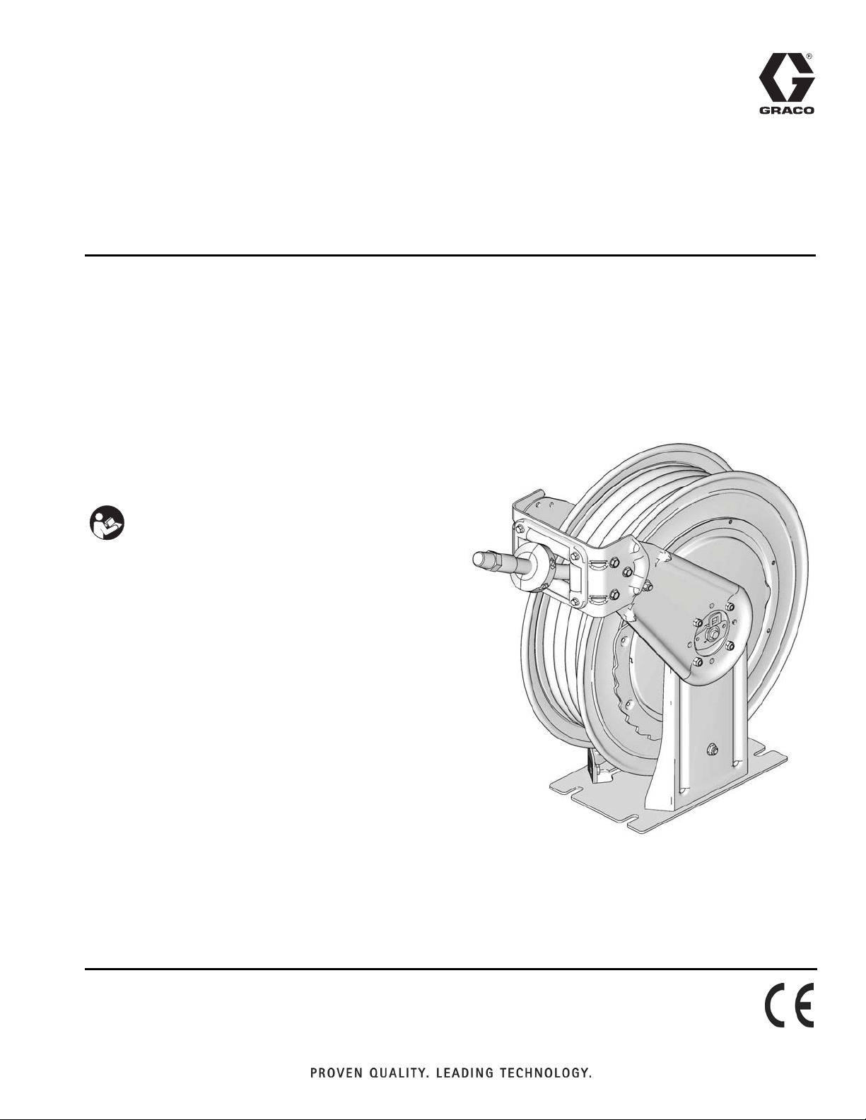
Instructions
XD Diesel Exhaust
Fluid (DEF) Hose
Reels
For use with Diesel Exhaust Fluid only. For professional use only.
Not approved for use in European explosive atmosphere locations.
Application markets include: mobile equipment servicing
and industrial plants.
Models: Page 3
3A1767A
ENG
Important Safety Instructions
Read all warnings and instructions in this
manual. Save these instructions.
ti13980
Page 2
Warnings
Warnings
The following warnings are for the setup, use, grounding, maintenance, and repair of this equipment. The exclamation point symbol alerts you to a general warning and the hazard symbol refers to procedure-specific risk. Refer back
to these warnings. Additional, product-specific warnings may be found throughout the body of this manual where
applicable.
WARNING
FIRE AND EXPLOSION HAZARD
When flammable fluids are present in the work area, such as gasoline and windshield wiper fluid, be
aware that flammable fumes can ignite or explode. To help prevent fire and explosion:
• Use equipment only in well ventilated area.
• Eliminate all ignition sources, such as cigarettes and portable electric lamps.
• Keep work area free of debris, including rags and spilled or open containers of solvent and gasoline.
• Do not plug or unplug power cords or turn lights on or off when flammable fumes are present.
• Ground all equipment in the work area.
• Use only grounded hoses.
• If there is static sparking or you feel a shock, stop operation immediately. Do not use equipment
until you identify and correct the problem.
• Keep a working fire extinguisher in the work area.
EQUIPMENT MISUSE HAZARD
Misuse can cause death or serious injury.
• Do not operate the unit when fatigued or under the influence of drugs or alcohol.
• Do not exceed the maximum working pressure or temperature rating of the lowest rated system
component. See Technical Data in all equipment manuals.
• Use fluids and solvents that are compatible with equipment wetted parts. See Technical Data in all
equipment manuals. Read fluid and solvent manufacturer’s warnings. For complete information
about your material, request MSDS from distributor or retailer.
• Do not leave the work area while equipment is energized or under pressure. Turn off all equipment
and follow the Pressure Relief Procedure when equipment is not in use.
• Check equipment daily. Repair or replace worn or damaged parts immediately with genuine manufacturer’s replacement parts only.
• Do not alter or modify equipment.
• Use equipment only for its intended purpose. Call your distributor for information.
• Route hoses and cables away from traffic areas, sharp edges, moving parts, and hot surfaces.
• Do not kink or over bend hoses or use hoses to pull equipment.
• Keep children and animals away from work area.
• Comply with all applicable safety regulations.
PRESSURIZED EQUIPMENT HAZARD
Fluid from the gun/dispense valve, leaks, or ruptured components can splash in the eyes or on skin
and cause serious injury.
• Follow the Pressure Relief Procedure when you stop spraying and before cleaning, checking, or
servicing equipment.
• Tighten all fluid connections before operating the equipment.
• Check hoses, tubes, and couplings daily. Replace worn or damaged parts immediately.
2 3A1767A
Page 3
Models
Warnings
WARNING
MOVING PARTS HAZARD
Moving parts can pinch, cut or amputate fingers and other body parts.
• Keep clear of moving parts.
• Do not operate equipment with protective guards or covers removed.
• Pressurized equipment can start without warning. Before checking, moving, or servicing equipment,
follow the Pressure Relief Procedure and disconnect all power sources.
PERSONAL PROTECTIVE EQUIPMENT
You must wear appropriate protective equipment when operating, servicing, or when in the operating
area of the equipment to help protect you from serious injury, including eye injury, hearing loss,
inhalation of toxic fumes, and burns. This equipment includes but is not limited to:
• Protective eyewear, and hearing protection.
• Respirators, protective clothing, and gloves as recommended by the fluid and solvent manufacturer.
Each model shown in the table below is available in several colors. The last character of each model no. indicates the
hose reel color. A = white, B = Metallic Blue and F = Yellow. On the table below, this last character is represented by
the generic # symbol. For example, to show the complete model number for a white HSDD5# model hose reel, the
symbol # is replaced with “A”. The complete model number is: HSDD5A.
Model No. Application
HSDD5# Diesel Exhaust Fluid 3/4 inch 50 3.4 0.34
HSDDD# Diesel Exhaust Fluid 3/4 inch 50 3.4 0.34
Hose
Size
Maximum Pressure
PSI Bar Mpa
3A1767A 3
Page 4
Installation
Installation
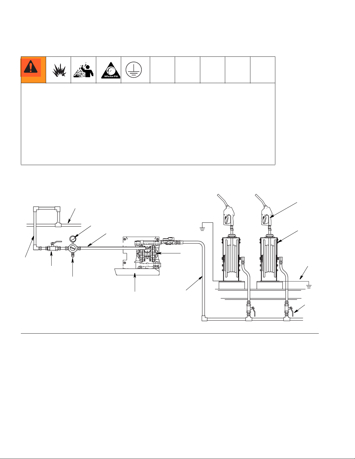
A bleed-type master air valve (E), thermal relief valve (H) and fluid drain valve (J) are
required in your system installation. These (user supplied) components help reduce the risk of
serious injury.
• The hose reel must be grounded.
•The bleed-type master air valve (E) relieves air trapped between this valve and the pump
after the air is shut off. Trapped air can cause the pump to cycle unexpectedly, therefore
locate the valve close to the pump.
•The thermal relief valve (H) and fluid drain valve (J) assist in relieving fluid pressure in the
displacement pump, hose and dispense valve. Triggering the dispensing valve (N) to relieve
pressure may not be sufficient. Open the fluid drain valve (J) to relieve fluid pressure that
may be captured elsewhere in the system.
Typical Installation Layout
.
A
A
F
C
D
B
B
F
IG. 1
A Main air supply
B Pump air supply
C Air regulator
D Bleed-type master air valve (user supplied, required)
EPump
F Grounding wire (user supplied, required for pump and
hose reel)
G Fluid line
H Hose reel
J Dispensing valve
K Air Supply Line
L Nozzle Tray
M Safety Valve (set to 50 psi (3.4 bar, 03.4 MPa)
N Fluid Shutoff Valve
C
D
M
E
K
G
H
L
J
N
H
E
M
F
P
K
J
G
G
K
N
L
ti13981
4 3A1767A
Page 5
Pressure Relief Procedure
1. 2.
Installation
3A1767A 5
Page 6
Installation
All Mountings
To reduce the risk of injury, be sure the mounting surface and mounting screws are strong enough to support the reels, weight of the fluids and stress caused
by hard pulls on the service hoses. See Technical
Data, page 16 for weights of hose reel assemblies.
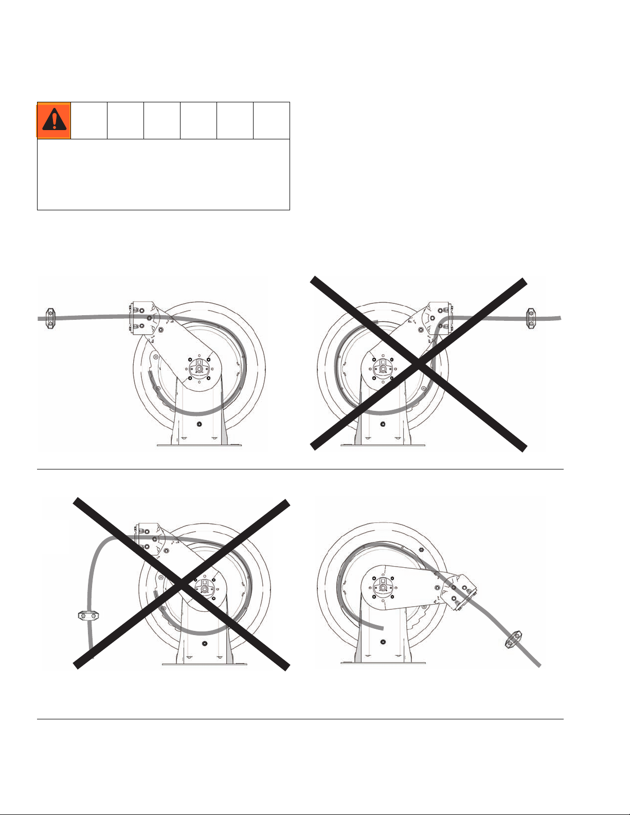
NOTE: Reels perform best when arm allows hose to pull
straight off the spool as shown in F
IG. 2 and FIG. 3.
FIG. 2
IG. 3
F
6 3A1767A
Page 7

Wall Mounting
1. A = Screws 2. A = Screws
A
A
Maximum distance to
floor - 16 ft (4.87 m)
ti13982
Installation
ti13983
Ceiling Mounting
1. A = Screws 2. A = Screws
A
A
Maximum distance to
floor - 16 ft (4.87 m)
3A1767A 7
Page 8

Installation
Truck Bed Mounting
1. A = Screws
A
Changing Position of Guide Arms (30)
1. Remove nuts (33). Reposition guide arms (30) to
new location.
30
33
2. Reinstall nuts (33). Torque to 25 - 35 ft lbs (33.9 to
47.5 N
33
·m).
30
8 3A1767A
Page 9

Changing Hose Guide (31) Position
Installation
1. Remove screws (52) and nuts (53) (not shown).
Reposition hose guide (31) to new location.
52
52
31
2. Reinstall screws (52) and nuts (53) (not shown).
Torque to 25 - 35 ft lbs (33.9 to 47.5 N
52
·m).
52
31
3A1767A 9
Page 10

Installation
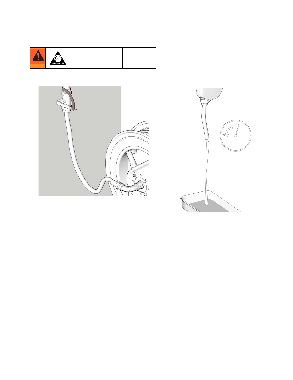
Flushing
Before installing meter or dispense valve to end of hose, flush supply line with a solvent compatible with the fluid you
are dispensing.
1. Place end of hose in waste container. 2. Blow out entire supply line with air.
3. Flush equipment with DEF until fluid runs clear.
10 3A1767A
Page 11

Adjusting Spring Tension
Adjusting Spring Tension
Increasing Spring Tension
Uncontrolled spinning of the hose reel could cause
serious injury if you are hit by the hose or the adjusting
tool (C).
• Never allow the reel to spin freely.
• Always grasp the tool firmly with both hands when
adjusting tension.
• The reel must be bolted securely in place when
making adjustments.
1. Loosen (A) 3-5 turns. Do not remove (A)! 2. Loosen (B) 3-5 turns. Do not remove (B) yet.
A
B
3A1767A 11
Page 12

Adjusting Spring Tension
3. Insert tool (C) in opening. Hold tool (C) firmly to
engage spring force before removing screws (B).
C
B
5. Replace one screw (B). Leave tool (C) in place. 6. Remove tool (C).
C
B
4. Turn tool (C) one full turn clockwise.
C
B
7. Pull hose to test tension. Repeat 3 - 7 if necessary. 8. Replace and tighten screws (B) and (A).
if
12 3A1767A
B
B
A
Page 13

Adjusting Spring Tension
Decreasing Spring Tension
Uncontrolled spinning of the hose reel could cause
serious injury if you are hit by the hose.
• Never allow the reel to spin freely.
• Always grasp the tool firmly with both hands when
adjusting tension.
• The reel must be bolted securely in place when
making adjustments.
1. Loosen (A) 3-5 turns. Do not remove (A)! 2. Loosen (B) 3-5 turns. Do not remove (B) yet.
A
3. Insert tool (C) in opening. Hold tool (C) firmly to
engage spring force before removing screws (B).
C
B
4. Turn tool (C) one full turn counter-clockwise.
C
B
3A1767A 13
B
Page 14

Adjusting Spring Tension
5. Replace one screw (B). Leave tool (C) in place. 6. Remove tool (C).
C
B
7. Pull hose to test tension. Repeat 3 - 7 if necessary. 8. Replace and tighten screws (B) and (A).
if
B
A
B
14 3A1767A
Page 15

Hose Stopper Installation
1. 2.
ti13525
Hose Stopper Installation
Installing Nozzle
1.
3A1767A 15
Page 16

Parts
Parts
Ref.
No. Part No. Description Qty
1‡ SHAFT, spring (not shown) 1
2 15Y781 WASHER, flat (not shown) 1
3† KIT, swivel, shaft 1
4‡ KEY, square (not shown) 1
5‡ HUB, power, spring 1
7‡ WASHER, flat, spring side 1
9‡ FLANGE, set, black 1
10‡ SPRING, power, 21 turn (not
shown)
11‡ COVER, spring, black (not shown) 1
12‡ GASKET (not shown) 1
14 15Y122 ADJUSTER, power spring 1
15 277867 WASHER, flat, square center 1
16 15U581 WASHER, flat 31 id 1
17 16A719 WASHER, flat 1
18 278151 SCREW, swivel shaft 1
19 107100 SCREW, cap 2
20† 125264 PACKING, o-ring 2
22† SWIVEL, elbow 1
24 16A146 BASE, painted, all models white 1
16A147 BASE, painted, all models metallic
blue
16A148 BASE, painted, all models yellow 1
16A149 BASE, painted, all models desert
sand
25 15U448 RING, retaining, ext, 22mm 1
26 16A134 PEDESTAL, arm, swivel side, all
models white
16A135 PEDESTAL, arm, swivel side, all
models metallic blue
16A136 PEDESTAL, arm, swivel side, all
models, yellow
16A137 PEDESTAL, arm, swivel side, all
models desert sand
27 16A691 SCREW, socket head 2
28 125242 HOSE, DEF, 50 ft, 3/4 BSPP x 3/4
BSPP (HSDD5# models only)
30 16A121 ARM, guide, all models, white 2
16A122 ARM, guide, all models, metallic
blue
16A123 ARM, guide, all models, yellow 2
16A124 ARM, guide, all models, desert
sand
31 16A140 GUIDE, hose, all models, white 1
16A141 GUIDE, hose, all models, metallic
blue
16A142 GUIDE, hose, all models, yellow 1
16A143 GUIDE, hose, all models, desert
sand
32 125265 NUT, hex, 3/4 x 14 BSPP 1
33 104541 NUT, lock 8
34◆★ BRACKET, roller 1
35◆★ PIN, roller 2
Ref.
No. Part No. Description Qty
36◆★ BOLT, m6x 20 lg w/patch 4
37◆★ ROLLER, hose 2
38◆★ PIN, roller 2
39◆★ ROLLER, hose 2
40❖ NUT, lock, hex 1
41❖ BUSHING, pawl (not shown) 1
42❖ KIT, pawl, ratchet 1
43❖ BOLT, m10 x 40 lg 1
1
44❖ SPRING, sst 1
46▲ 15W036 LABEL, Warning 1
48❖ SCREW, button head m6 4
49✓ 218341 STOP, hose (HSDD5# models only) 2
50✓ SCREW, mach, phil, pn hd,
(HSDD5# models only)
51✓ NUT, hex, jam (HSDD5# models
only)
52 111799 SCREW, cap, hex hd 6
53 16A390 NUT, hex 6
59❖ RATCHET, Aluminum 1
1
▲ Replacement Danger and Warning labels, tags and
cards are available at no cost.
† Included in Swivel and Seal Replacement Kit 24K259
1
❖ Included in Ratchet and Latch Replacement Kit
24C995
1
◆ Included in Hose Guide Kit 24C996
★ Included in Bulk Head Hose Guide Kit 24C997
1
‡ Included in Spool Replacement Kit 24C998
1
✓ Included in Hose Stop Replacement Kit 237873
1
1
2
2
1
1
2
2
16 3A1767A
Page 17

52
Parts
52
40
46
33
51
18
49
37
35
39
53
44
16
42
15
36
43
19
14
25
28
50
38
34
31
48
17
59
53
30
3
5
20
32
26
7
27
22
9
29
30
3A1767A 17
Page 18

Technical Data
Technical Data
Model No. Application Hose Size
HSDD5#
HSDDD#
HSDD5#
HSDDD#
Maximum Dry Weight (without hose)
HS Models: 98 pounds (44.5 kg)
Operating Temperature Range: 12°F (-11°C) to 140°F (60°C)
Sound Data all models:
Sound Pressure - 85.8 dB(A) calculated at 1 meter per ISO9614.2
Sound Power - 94.9 dB(A) measured per ISO 9614-2
Wetted Par ts SST, Compatible Polyurethane, Fluoroelastomer
Dimensions
Maximum Pressure
PSI Bar Mpa
DEF
Bare N/A 50 3.4 0.34
3/4 in. x 50 ft.
(19 mm x 1524 cm)
50 3.4 0.34
Inlet
(BSPP)
3/4 inch 3/4 inch
3/4 inch 3/4 inch
Outlet
(BSPP)
588 mm
(23.10 in.)
229 mm
(9.0 in.)
561.73 mm
(22.12 in.)
350 mm
(13.77 in.)
18 3A1767A
Page 19

Mounting Pattern
14 mm (1/2 in.)
bolts - 4X
Technical Data
131.76 mm
(5.187 in.)
293.86 mm
(11.57 in.)
3A1767A 19
Page 20

Graco Hose Reel Warranty
Graco warrants all equipment referenced in this document which is manufactured by Graco and bearing its name to be free from defects in
material and workmanship on the date of sale to the original purchaser for use. With the exception of any special, extended, or limited warranty
published by Graco, Graco will, for a period as defined in the table below from the date of sale, repair or replace equipment covered by this
warranty and determined by Graco to be defective. This warranty applies only when the equipment is installed, operated and maintained in
accordance with Graco’s written recommendations.
Component Warranty Period
Wear parts, including but not limited to: hose,
swivel seals, roller guide 12 months
Reel structural components and spring 36 months
Bare hose reels: all components 12 months
This warranty does not cover, and Graco shall not be liable for general wear and tear, or any malfunction, damage or wear caused by faulty
installation, misapplication, abrasion, corrosion, inadequate or improper maintenance, negligence, accident, tampering, or substitution of
non-Graco component parts. Nor shall Graco be liable for malfunction, damage or wear caused by the incompatibility of Graco equipment with
structures, accessories, equipment or materials not supplied by Graco, or the improper design, manufacture, installation, operation or
maintenance of structures, accessories, equipment or materials not supplied by Graco.
This warranty is conditioned upon the prepaid return of the equipment claimed to be defective to an authorized Graco distributor for verification of
the claimed defect. If the claimed defect is verified, Graco will repair or replace free of charge any defective parts. The equipment will be returned
to the original purchaser transportation prepaid. If inspection of the equipment does not disclose any defect in material or workmanship, repairs will
be made at a reasonable charge, which charges may include the costs of parts, labor, and transportation.
THIS WARRANTY IS EXCLUSIVE, AND IS IN LIEU OF ANY OTHER WARRANTIES, EXPRESS OR IMPLIED, INCLUDING BUT NOT LIMITED
TO WARRANTY OF MERCHANTABILITY OR WARRANTY OF FITNESS FOR A PARTICULAR PURPOSE.
Graco’s sole obligation and buyer’s sole remedy for any breach of warranty shall be as set forth above. The buyer agrees that no other remedy
(including, but not limited to, incidental or consequential damages for lost profits, lost sales, injury to person or property, or any other incidental or
consequential loss) shall be available. Any action for breach of warranty must be brought within 48 months of the date of sale, or 24 months for all
other parts.
GRACO MAKES NO WARRANTY, AND DISCLAIMS ALL IMPLIED WARRANTIES OF MERCHANTABILITY AND FITNESS FOR A
PARTICULAR PURPOSE, IN CONNECTION WITH ACCESSORIES, EQUIPMENT, MATERIALS OR COMPONENTS SOLD BUT NOT
MANUFACTURED BY GRACO. These items sold, but not manufactured by Graco (such as electric motors, switches, hose, etc.), are subject to
the warranty, if any, of their manufacturer. Graco will provide purchaser with reasonable assistance in making any claim for breach of these
warranties.
In no event will Graco be liable for indirect, incidental, special or consequential damages resulting from Graco supplying equipment hereunder, or
the furnishing, performance, or use of any products or other goods sold hereto, whether due to a breach of contract, breach of warranty, the
negligence of Graco, or otherwise.
FOR GRACO CANADA CUSTOMERS
The Parties acknowledge that they have required that the present document, as well as all documents, notices and legal proceedings entered into,
given or instituted pursuant hereto or relating directly or indirectly hereto, be drawn up in English. Les parties reconnaissent avoir convenu que la
rédaction du présente document sera en Anglais, ainsi que tous documents, avis et procédures judiciaires exécutés, donnés ou intentés, à la suite
de ou en rapport, directement ou indirectement, avec les procédures concernées.
Graco Information
For the latest information about Graco products, visit www.graco.com.
TO PLACE AN ORDER, contact your Graco distributor or call to identify the nearest distributor.
Phone: 612-623-6928 or Toll Free: 1-800-533-9655, Fax: 612-378-3590
All written and visual data contained in this document reflects the latest product information available at the time of publication.
Graco reserves the right to make changes at any time without notice.
Original instructions. This manual contains English. MM 3A1767
Graco Headquarters: Minneapolis
International Offices: Belgium, China, Japan, Korea
GRACO INC. P.O. BOX 1441 MINNEAPOLIS, MN 55440-1441
Copyright 2011, Graco Inc. is registered to ISO 9001
www.graco.com
5/2011
 Loading...