

Graco ThermoLazer 200TC, ThermoLazer 300TC, ThermoLazer ProMelt, ThermoLazer 200 Repair Manual
ti23074a
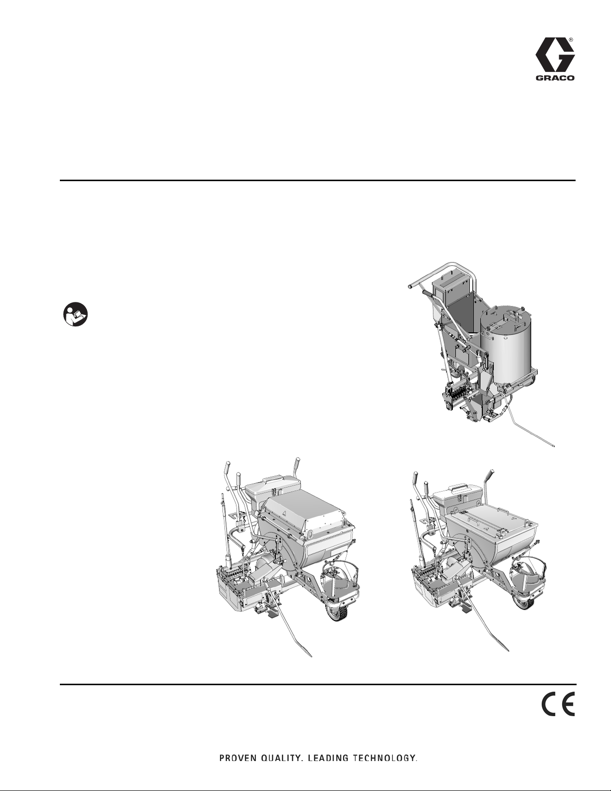
ThermoLazer 300TC
ThermoLazer ProMelt
ti23073a
ThermoLazer 200/200TC
ti22634b
Repair
ThermoLazer® 200/200TC/300TC and
ThermoLazer ProMelt™ Pavement Marking
Systems
- For professional application of thermoplastic traffic marking compound materials
(reflective beads applied simultaneously with screeding) -
- For outdoor use only (not to be operated in rain or damp conditions) -
Fuel: LP Gas (Propane Vapor)
Burner capacities: See Technical Data, page 47
Material capacity (max): 200-300 lb (91-136 kg)
IMPORTANT SAFETY INSTRUCTIONS
Read all warnings and instructions in this
manual. Save these instructions.
Related Manuals:
Operation 3A1319
Parts 3A1321
Double Bead 3A0004
SmartDie
FlexDie
™
™
II
3A1738
3A1738
3A1320L
EN

System Chart
System Chart
SmartDie II used on ThermoLazer 300TC/ProMelt only.
Smart Die II
Smart Die Description
Part No.
17A173 2 in. (5 cm)
24H431 3 in. (8 cm)
24H426 4 in. (10 cm)
17J250 4.75 in. (12 cm)
24H432 5 in. (13 cm)
24H427 6 in. (15 cm)
24H433 7 in. (18 cm)
24H428 8 in. (20 cm)
24H434 9 in. (22.5 cm)
24H429 10 in. (25 cm)
24H430 12 in. (30 cm)
‡17A174
24H437 3-3-3 in. (8-8-8 cm)
24H435 4-3-4 in. (10-8-10 cm)
24H436 4-4-4 in. (10-10-10 cm)
24J785 4-6-4 in. (10-15-10 cm)
‡17A175
‡17R378
‡26C273
16 in. (40 cm)
6-4-6 in. (15-10-15 cm)
5-5-5 in. (13-13-13 cm)
6-3-6 in. (15-8-15 cm)
‡ Requires 16” (40 cm) Conversion Bead System Kit for 300TC/ProMelt Only.
- 17B190 Kit, accy, 16” (40 cm) Single Drop Bead System
- 17B189 Kit, accy, 16” (40 cm) Double Drop Bead Box (requires 17B190 to be installed)
FlexDie used on ThermoLazer 200/200TC only.
FlexDie
Part No.
16Y661 2 in. (5 cm)
16Y662 3 in. (8 cm)
16Y320 4 in. (10 cm)
16Y663 5 in. (12 cm)
16Y190 6 in. (15 cm)
16Y664 7 in. (18 cm)
16Y326 8 in. (20 cm)
16Y665 9 in. (22.5 cm)
16Y332 10 in. (25 cm)
16Y207 12 in. (30 cm)
16Y338 3-3-3 in. (8-8-8 cm)
16Y352 4-3-4 in. (10-8-10 cm)
16Y666 4-2-4 in. (10-5-10 cm)
16Y363 4-4-4 in. (10-10-10 cm)
FlexDie Description
2 3A1320L

Contents
System Chart
System Chart . . . . . . . . . . . . . . . . . . . . . . . . . . . . . . 2
Warnings . . . . . . . . . . . . . . . . . . . . . . . . . . . . . . . . . 4
Kettle Gas Safety Valve,
Kettle Temperature Control, and
Kettle Thermopile Diagnosis . . . . . . . . . . . . . . 6
Kettle Temperature Control . . . . . . . . . . . . . . . . . . 7
Replacement . . . . . . . . . . . . . . . . . . . . . . . . . . . . 7
Calibration . . . . . . . . . . . . . . . . . . . . . . . . . . . . . . 9
Kettle Thermometer . . . . . . . . . . . . . . . . . . . . . . . . 10
Replacement . . . . . . . . . . . . . . . . . . . . . . . . . . . 10
Calibration . . . . . . . . . . . . . . . . . . . . . . . . . . . . . 10
Adjust Kettle Pilot Igniter Electrode Gap . . . . . . 11
Kettle Over-Temperature Switch Replacement
(ProMelt only) . . . . . . . . . . . . . . . . . . . . . . . . . 11
Thermopile Replacement . . . . . . . . . . . . . . . . . . . 12
Removal and Installation of Electrode . . . . . . . . . 16
Pilot Burner . . . . . . . . . . . . . . . . . . . . . . . . . . . . . . 18
(ThermoLazer 200TC/300TC/ProMelt) . . . . . . . 18
Cleaning Kettle Main Burner Gas Lines . . . . . . . 20
Cleaning Kettle Pilot Burner Gas Lines . . . . . . . . 20
Securing Bead Dispenser Wheel . . . . . . . . . . . . . 21
Bead Dispense Tension Adjustment . . . . . . . . . 21
Linkage Rod Adjustment . . . . . . . . . . . . . . . . . . 21
Screed Box/Bead Dispenser Box Actuator . . . . . 22
Screed Box Pivot Arm Loading . . . . . . . . . . . . . . 22
(ThermoLazer 300TC/ProMelt only) . . . . . . . . . 22
Carbide Runner Replacement on Smart Die II
(300TC/ProMelt) . . . . . . . . . . . . . . . . . . . . . . . . 23
Carbide Runner Replacement on FlexDie
(200/200TC) . . . . . . . . . . . . . . . . . . . . . . . . . . . . 24
Kettle Gas Regulator Replacement . . . . . . . . . . . 25
ThermoLazer 200/200TC . . . . . . . . . . . . . . . . . . 25
ThermoLazer 300TC . . . . . . . . . . . . . . . . . . . . . 26
ThermoLazer ProMelt . . . . . . . . . . . . . . . . . . . . 27
Torch and Screed Burners Gas Regulator
Replacement (ThermoLazer 300TC/ProMelt) 28
Rear Screed Burner Assembly . . . . . . . . . . . . . . . 29
Front Screed Burner Assembly . . . . . . . . . . . . . . 30
(ThermoLazer 300TC/ProMelt) . . . . . . . . . . . . . 30
Screed Burner . . . . . . . . . . . . . . . . . . . . . . . . . . . . 32
(ThermoLazer 300TC/ProMelt) . . . . . . . . . . . . . 32
Screed Burner . . . . . . . . . . . . . . . . . . . . . . . . . . . . 33
Main Gas Filter
(ThermoLazer 300TC/ProMelt) . . . . . . . . . . . . 34
Screed Burner Filter . . . . . . . . . . . . . . . . . . . . . . . . 34
Troubleshooting . . . . . . . . . . . . . . . . . . . . . . . . . . . 35
Piping Diagram . . . . . . . . . . . . . . . . . . . . . . . . . . . . 41
ThermoLazer 200 . . . . . . . . . . . . . . . . . . . . . . . 41
ThermoLazer 200TC . . . . . . . . . . . . . . . . . . . . . 42
ThermoLazer 300TC/ProMelt . . . . . . . . . . . . . . 43
Wiring Diagram . . . . . . . . . . . . . . . . . . . . . . . . . . . . 44
ThermoLazer 200TC . . . . . . . . . . . . . . . . . . . . . 44
ThermoLazer 300TC . . . . . . . . . . . . . . . . . . . . . 45
ThermoLazer ProMelt . . . . . . . . . . . . . . . . . . . . 46
Technical Data . . . . . . . . . . . . . . . . . . . . . . . . . . . . 47
Graco Standard Warranty . . . . . . . . . . . . . . . . . . . 48
Graco Information . . . . . . . . . . . . . . . . . . . . . . . . . 48
3A1320L 3
Warnings
WARNING
Warnings
The following warnings are for the setup, use, grounding, maintenance, and repair of this equipment. The exclamation point symbol alerts you to a general warning and the hazard symbols refer to procedure-specific risks. When
these symbols appear in the body of this manual or on warning labels, refer back to these Warnings. Product-specific
hazard symbols and warnings not covered in this section may appear throughout the body of this manual where
applicable.
FIRE AND EXPLOSION HAZARD
Flammable fumes and liquids, such as propane gas, gasoline and combustible fuel, in work area can
ignite or explode. To help prevent fire and explosion:
• Do not use equipment unless fully trained and qualified.
• Do not allow open containers of flammables within 25 ft (7.6 m) of equipment. Do not operate equipment within 10 ft (3 m) of any structure, combustible material, or other gas cylinders.
• Shut off all burners when adding fuel to equipment.
• Close the tank shut-off valve immediately if you smell propane gas; extinguish all open flames. If gas
odor continues, keep away from equipment and immediately call the fire department.
• Follow lighting instructions for the burner and torch.
• Do not heat thermoplastic traffic marking compound material above its maximum temperature rating.
• Fire extinguisher equipment shall be present and working.
• Keep work area free of debris, including solvent, rags and gasoline.
EQUIPMENT MISUSE HAZARD
Misuse can cause death or serious injury.
• Do not leave equipment unattended.
• Keep children and animals away from work area.
• Do not exceed the maximum working pressure or temperature rating of the lowest rated system
component. See Technical Data in all equipment manuals.
• Check equipment daily. Repair or replace worn or damaged parts immediately with genuine
manufacturer’s replacement parts only.
• Do not alter or modify equipment.
• Use equipment only for its intended purpose. Call your Graco distributor for information.
• Do not fill material beyond maximum capacity.
• Route gas lines, hoses, wires and cables away from traffic areas, sharp edges, moving parts, and hot
surfaces.
• Do not kink or overbend gas lines.
• Do not override or defeat safety devices.
• Do not operate the unit when fatigued or under the influence of drugs or alcohol.
BURN HAZARD
Equipment surfaces and fluid that is heated can become very hot during operation. To avoid severe
burns:
• Do not touch hot fluid or equipment.
CARBON MONOXIDE HAZARD
Exhaust contains poisonous carbon monoxide, which is colorless and odorless. Breathing carbon
monoxide can cause death. Do not operate in an enclosed area.
TOXIC FLUID OR FUMES HAZARD
Toxic fluids or fumes can cause serious injury or death if splashed in the eyes or on skin, inhaled, or swallowed.
• Read MSDS to know the specific hazards of the materials you are using.
4 3A1320L
Warnings
WARNING
PERSONAL PROTECTIVE EQUIPMENT
Wear appropriate protective equipment when in the work area to help prevent serious injury, including eye
injury, hearing loss, inhalation of toxic fumes, and burns. This protective equipment includes but is not
limited to:
• Clothing and respirator as recommended by the fluid, material, and solvent manufacturer.
• Gloves, shoes, overalls, face shield, hat, etc. rated for elevated temperatures of at least 500° F
(260° C).
CALIFORNIA PROPOSITION 65
Exhaust from this product contains a chemical known to the State of California to cause
cancer, birth defects or other reproductive harm.
This product contains a chemical known to the State of California to cause cancer, birth defects or other
reproductive harm. Wash hands after handling.
3A1320L 5
Kettle Gas Safety Valve, Kettle Temperature Control, and Kettle Thermopile Diagnosis
TH
TP
TH
TP
1
2
3
ti14524c
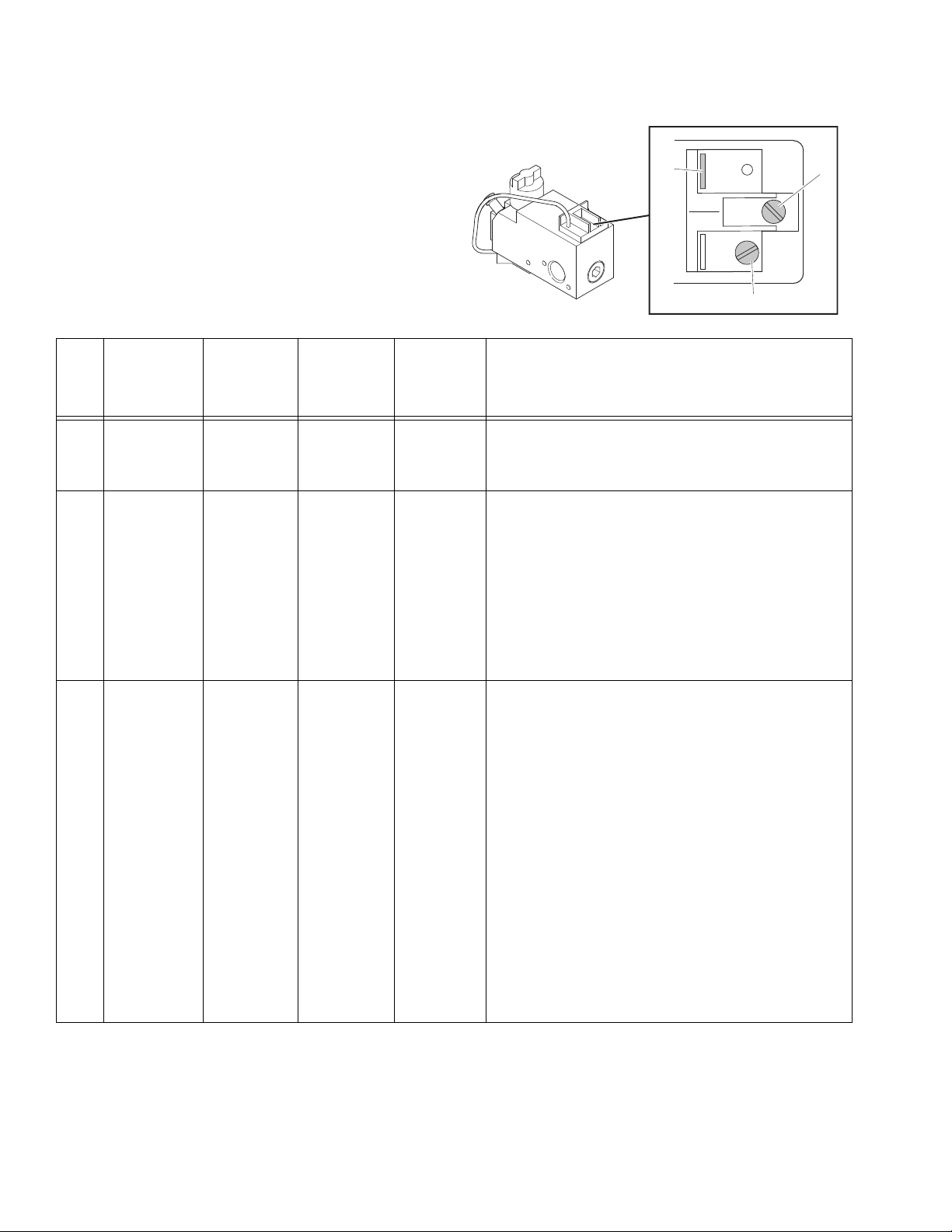
Terminal Connections
Kettle Gas Safety Valve,
Kettle Temperature Control, and
Kettle Thermopile Diagnosis
The gas safety valve, temperature control and thermopile can be checked by using a millivolt meter. Before
checking, make certain all electrical connections are
clean and tight.
Connect millivolt meter to appropriate terminals (see
Terminal Connections).
Status of
Part(s) to Be
Step
1 Gas safety
2 Temperature
Checked
valve
control
Temperature
Terminal
Connections
2 and 3 Closed Greater than
1 and 2 Closed Less than
Control
Contacts
Desired
Meter
Reading Diagnosis
If mV reading > 100 mV and the automatic valve (main
100 mV
80 mV
burners) does not come on, replace the gas safety valve.
If mV reading < 100mV, proceed with diagnostic steps 2
and 3.
If reading > 80 mV:
• Clean and tighten electrical connections at temperature control and gas safety valve.
• Check valve to make sure wires are in good condition. Replace as required.
• Rapidly change temperature setting on temperature
control to see if cycling cleans the contacts.
3 Gas safety
valve magnet
and
thermopile
1 and 2 Open Greater than
325 mV
If the preceding fails to give mV reading < 80 mV, replace
temperature control.
If mV reading < 325 mV:
• Clean and tighten all electrical connections.
• Adjust pilot burner to increase millivolt output (see
page 18).
If the preceding fails to give mV reading > 325 mV,
replace thermopile.
Check valve magnet after obtaining correct mV output for
thermopile:
• Ignite pilot burner only and allow the mV reading to
stabilize.
• Shut pilot burner (turn gas safety valve knob OFF).
Note the mV reading where magnet drops out.
If magnet unlocks at mV reading < 120 mV, the magnet is
OK. NOTE: When magnet unlocks a click can be heard
and mV reading may fluctuate slightly.
6 3A1320L
Kettle Temperature Control
ti14557a
ti14124a
AA
BB
ti17067a
ti17066a
ThermoLazer 300TC (24H622, 24H625)
ThermoLazer ProMelt
41
124, 318
41
124
(24H624)
ti22652a
ThermoLazer 200TC
Kettle Temperature Control
Replacement
When replacing temperature control, keep in mind that
the temperature probe is an integral part of the assembly. Do not make any sharp bends in the capillary tubing. Bends should be 0.25 in. (0.64 cm) in radius or
greater.
Be sure to seal capillary tubing with high temperature
mortar at kettle outlet.
Removal
8. Use screwdriver to remove four screws (221) and
remove temperature control enclosure (205) from
handle bar mounting plate (122).
9. Use screwdriver to disconnect wires (242 and 243
for ThermoLazer), (243 and 360 for ThermoLazer
ProMelt).
10. Use wrench and extension to remove nut (124) from
temperature probe (162).
11. Use needle-nosed pliers to remove clip (41) from
probe (162).
12. Pull probe (162) through nut and clamp openings.
13. Use flat screwdriver or a small chisel to chip away
mortar on inside and outside of kettle until probe
freely passes through.
14. Pull probe (162) completely out of kettle (14) and
remove from temperature control enclosure (205).
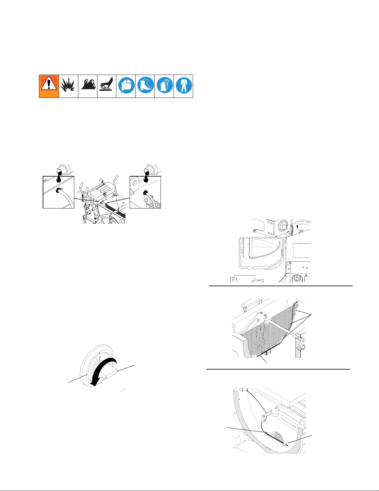
1. Empty kettle and clean all material out. Make sure
stud (318), nut (124), clip (41) and probe (162) are
completely free of material.
2. Use screwdriver to loosen hose clamps (160) and
disconnect hoses (189) from bead hopper (43).
3. Use wrench to remove four bolts (139) and remove
bead hopper (43).
4. Pull temperature capillary tube (162) and grommet
(350) free of heat shield (270).
5. Remove temperature control knob (AA) by hand.
6. Remove temperature control plastic 4-way insert
7. Use screwdriver to remove two screws on tempera-
from shaft. Insert behind knob (AA).
ture control slip-fit overlay ring (BB). Overlay ring
(BB) is attached to temperature control enclosure
(205).
3A1320L 7
15. .
Kettle Temperature Control
1
2
ti14124a
AA
BB
ti14124a
AA
BB
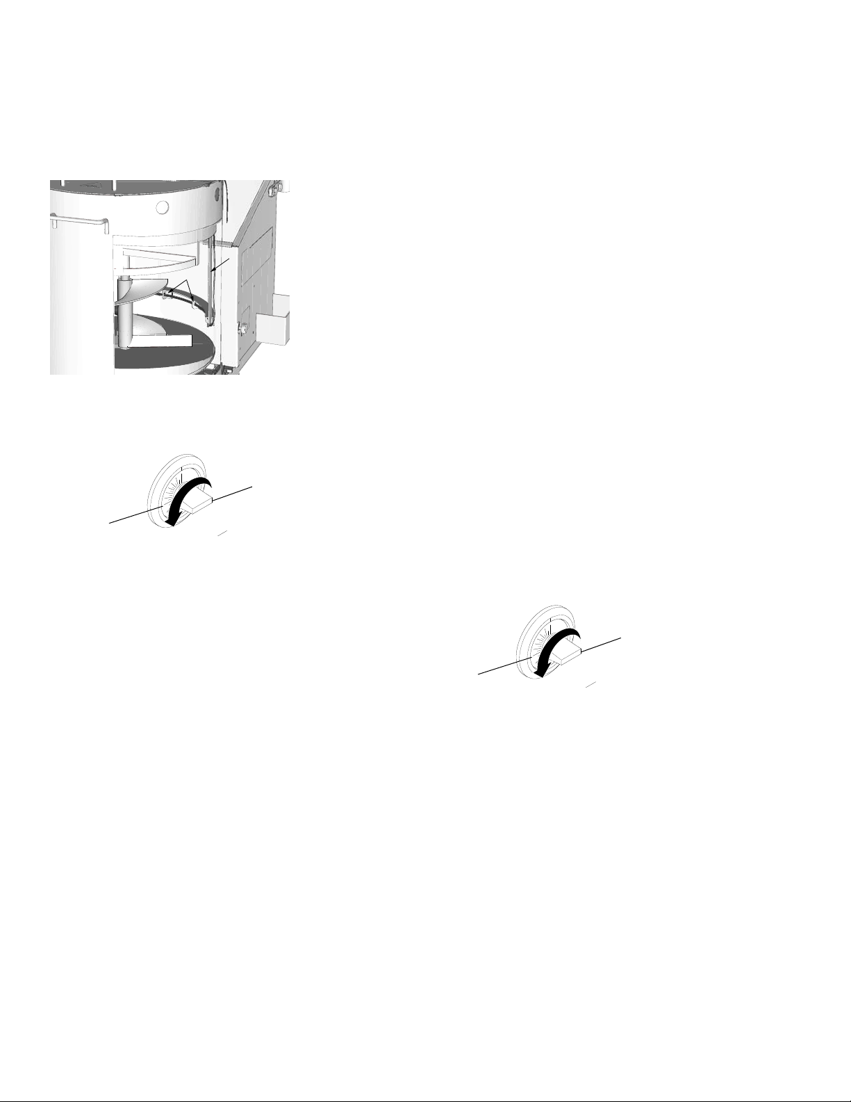
Installation (ThermoLazer 200TC)
1. Route tube through clips (1).
2. Route wire inside bracket (2) on inner wall of kettle.
3. Install temperature control (162) to temperature
control enclosure (205) with two screws supplied
with temperature control. Install overlay ring (BB)
parallel with temperature probe.
4. Route wires and probe capillary tubing so they will
not be pinched when installing temperature control
enclosure (205) to ThermoLazer handle bar mounting plate (122).
NOTE: For best results, keep probe capillary tubing
in spiral coil.
dle-nose pliers to secure probe inside clips (41).
*Torque stud (318) to 7-15 in-lb./079-1.69 N•m.
ProMelt: Route probe (162) through Z-clips (2)
welded to kettle (14). Route probe through stud
welded to kettle. Tighten* nut (124) to stud securing
probe. Secure probe to angle clip welded to kettle
with clip (41). Use needle-nose pliers to secure
probe inside clip(41).
*Torque nut (124) to 7-15 in-lb./079-1.69 N•m.
NOTE: Make sure probe cannot come into contact
with material agitator once installed.
4. Apply high temperature mortar to inside and outside
of kettle opening contact points after the probe is
installed and locked into position by the nut and
clamps.
5. ThermoLazer: Route wires (242, 243) through han-
dle bar mounting plate (122). Use screwdriver to
connect and tighten wires (242, 243) to temperature
control (162).
ProMelt: Route wires (243, 360) through handle bar
mounting plate (122). Use screwdriver to connect
and tighten wires (243, 360) to temperature control
(122).
6. Install temperature control (162) to temperature
control enclosure (205) with two screws supplied
with temperature control. Install overlay ring (BB)
parallel with temperature probe.
5. Install in bracket, then attach bracket to kettle.
6. Install plastic 4-way insert on temperature control
shaft.
7. Route wires and probe capillary tubing so they will
not be pinched when installing temperature control
7. Install temperature control knob (AA) on temperature control shaft.
Installation (ThermoLazer 300TC/ProMelt)
1. Route new probe (162) through grommet (350).
2. Route probe:
a. Between tube, lock (71) and bracket, handle,
mount, and tube (19).
enclosure (205) to ThermoLazer handle bar mounting plate (122).
NOTE: For best results, keep probe capillary tubing
in spiral coil.
8. Install temperature control enclosure (205) to ThermoLazer handle bar mounting plate (122) with four
screws (221).
9. Install plastic 4-way insert on temperature control
shaft.
b. Through slotted hole in heat shield (270). Insert
grommet (350) in heat shield hole.
c. Through kettle (14) probe opening.
3. ThermoLazer: Route probe through stud (318).
Insert stud through screen (150) and tighten* stud
(318) to screen (150) with nut (124). Secure probe
(162) to screen (150) with three clips (41). Use nee-
8 3A1320L
10. Install temperature control knob (AA) on temperature control shaft.
11. Install bead hopper (43) and use wrench to install
and tighten four bolts (139).
12. Connect hoses (189) to bead hopper (43) and use
screw driver to tighten hose clamps (160)

Kettle Temperature Control
ti14523a
Calibration
To Check Kettle Temperature Control Calibration:
1. Move unit to an area with no wind.
2. Turn temperature control to 400° F (204° C).
3. Agitate material for 4 to 5 minutes.
4. After control has reached steady state temperature
and burners do not cycle more than once per minute, insert remote calibrated temperature probe in
material and directly adjacent kettle temperature
control probe.
5. Compare temperature of remote calibrated temperature probe to temperature setting on temperature control.
6. If the temperature control setting is lower than the
remote calibrated temperature setting on temperature probe, turn adjusting screw clockwise. Every
1/4 in. turn will change temperature 35° F (19.4° C).
7. If the temperature control setting is higher than the
remote calibrated temperature probe, turn adjusting
screw counterclockwise--every 1/4 in. turn will
change temperature 35° F (19.4° C).
8. Recheck calibration by turning temperature control
to 410° F (210° C) and repeat steps 3-7.
3A1320L 9
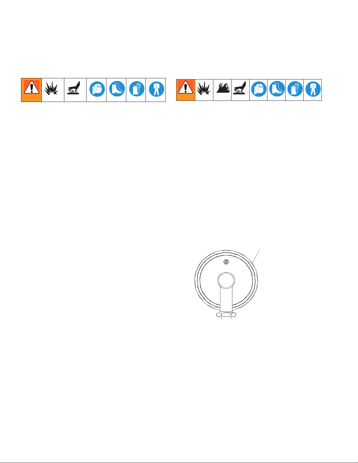
Kettle Thermometer
RESET
ti14525b
Adjusting Screw
Kettle Thermometer
Replacement
NOTE: The thermometer can only be replaced while the
material inside the kettle is warm. If material inside the
kettle is cold, it will adhere to the probe and cause it to
separate from the thermometer once it is unscrewed.
1. Empty material from kettle until material level is just
below the thermometer probe (162) (approximately
1 inch of material).
2. Unscrew thermometer (38) from kettle coupling.
NOTE: Look inside the kettle to make sure the
probe is rotating at the same rate as the thermometer as you unscrew it. If the probe is sticking, use the
hand torch to heat the probe and material so that
the probe can rotate freely.
Installation
1. Apply pipe sealant to thermometer (38) threads.
2. Install new thermometer into kettle coupling and
tighten. NOTE: Make sure the face of the thermometer is position toward the front of the unit for optimal viewing (an approximately 15 degree angle).
Calibration
To Check Kettle Thermometer Calibration:
1. Move ThermoLazer to an area with no wind.
2. Turn temperature control to 400° F (204° C).
3. Agitate material for 4 to 5 minutes.
4. After control has reached steady state temperature
and burners do not cycle more than once per minute, insert remote calibrated temperature probe in
material and directly adjacent kettle temperature
control probe.
5. Compare temperature of remote calibrated temperature probe to thermometer.
6. If kettle thermometer is lower than the remote calibrated temperature probe, turn adjusting screw
counterclockwise.
7. If the kettle thermometer is higher than the remote
calibrated temperature probe, turn adjusting screw
clockwise.
10 3A1320L
Adjust Kettle Pilot Igniter Electrode Gap
ti14519b
0.17 - 0.20 in.
7
ti17078b
Adjust Kettle Pilot Igniter
Electrode Gap
(ThermoLazer 300TC/ProMelt only)
1. Loosen screw (231).
2. Rotate ignitor electrode (7) until gap of 0.17 to 0.20
in. (0.43 to 0.51 cm) is achieved.
3. Retighten screw (231).
Kettle Over-Temperature
Switch Replacement
(ProMelt only)
Removal
1. Unscrew switch fitting from kettle. NOTE: To keep
wire sleeve from twisting, counter-rotate sleeve
when turning switch fitting.
2. Disconnect wire leads from switch terminals.
3. Unscrew switch and remove.
Installation
1. Apply anti-seize (LPS-04110 or equal) to switch
(339).
2. Install switch and torque to 120 - 140 in-lb (13.6 -
15.8 N•m).
3. Apply anti-seize (LPS-04110 or equal) to switch
fittings (343).
4. Connect wire leads (359 and 360) to switch.
5. Install switch fitting and torque to 180 - 200 in-lb
(20.3 - 22.6 N•m). NOTE: To keep wire sleeve from
twisting, counter-rotate sleeve when turning switch
fitting.
3A1320L 11
Thermopile Replacement
ti14128a
29
ti14880a
ThermoLazer 300TC/ProMelt Shown
ti14852a
320
28
ti14853a
13
ti14855a
357
28
ThermoLazer 300TC/ProMelt
only
ti14854a
28
71
ti25692b
421
ti25740a
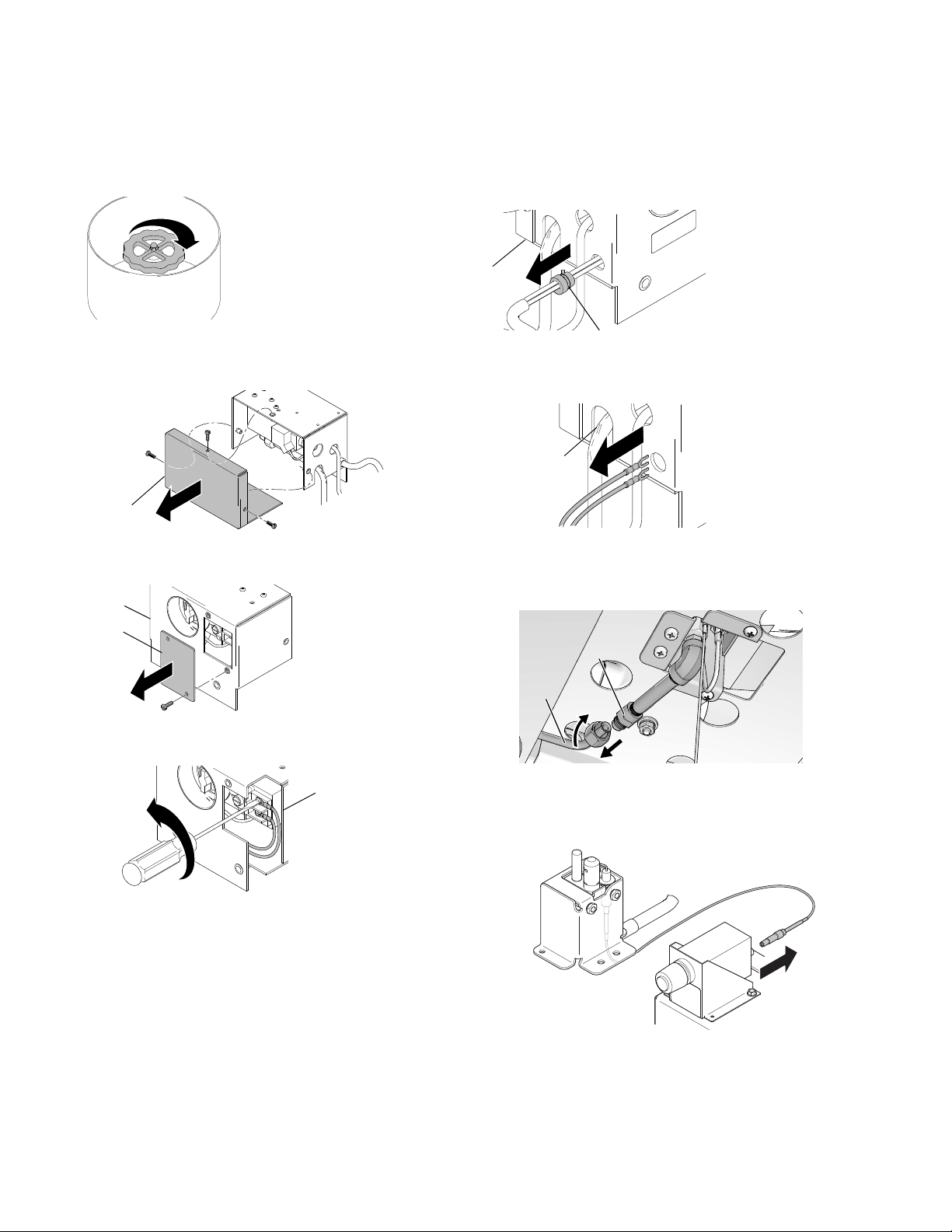
Thermopile Replacement
Removal
1. Shut off gas valve on LP-tank and disconnect hose.
2. Remove gas safety valve enclosure back cover
(29).
3. Remove cover (320) from gas safety valve enclosure (28).
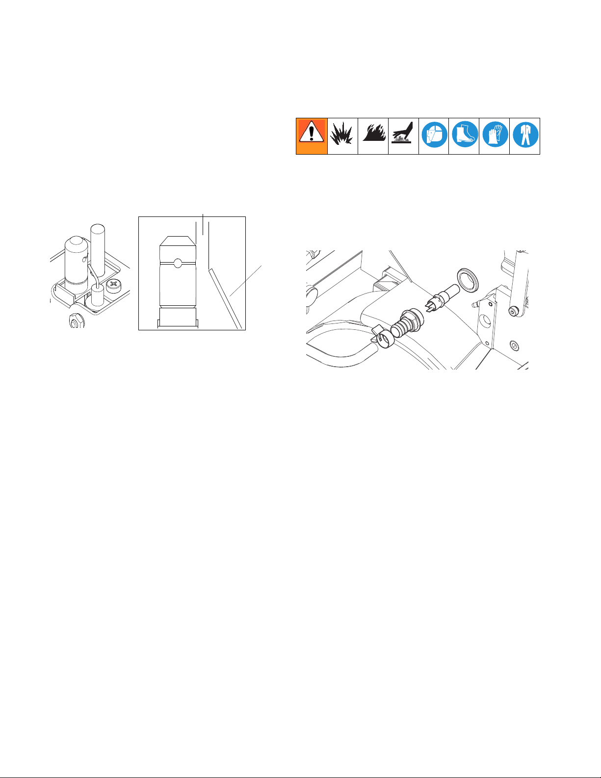
5. Remove wire strain relief fitting (357) from gas
safety valve enclosure (28).
6. Pull thermopile wire out of gas safety valve enclosure (28).
7. Disconnect gas pilot line (71) from flared adapter
(421). Only rotate the nut on gas pilot line (71), while
keeping flared adapter (421) stationary.
4. Disconnect thermopile wires from gas safety valve
(13).
8. Thermolazer 300
ThermoLazer 200TC/300TC/ProMelt
TC/ProMelt only: Disconnect
electrode lead (217) from pulse fire igniter (126).
Pull electrode out of wire sleeving.
12 3A1320L
Thermopile Replacement
319
18
244
ti25739b
ti25741b
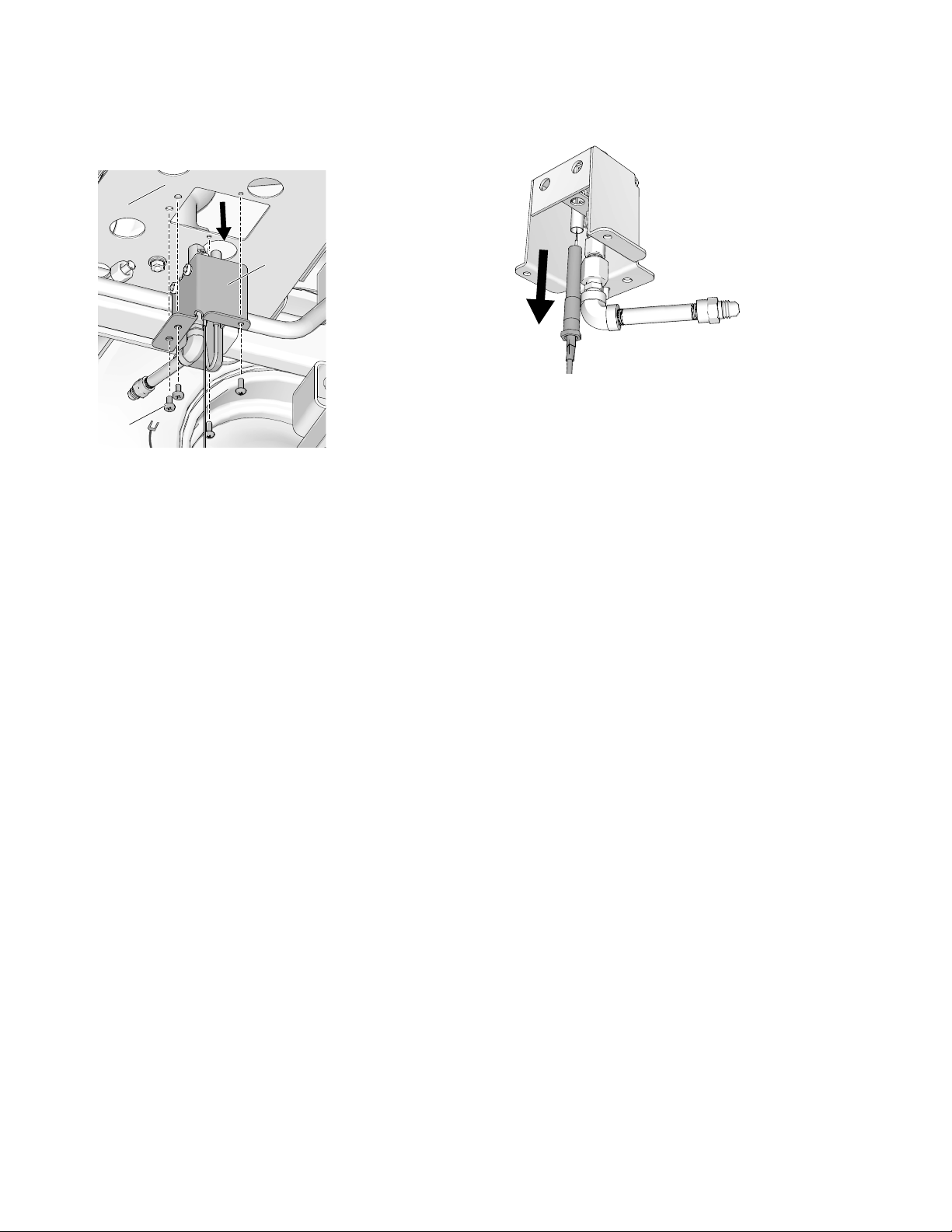
9. Remove gas pilot mounting housing (319) from gas
burner mounting plate (18). Disconnect ground lead
wire (244).
ThermoLazer 300TC/ProMelt
Shown
10. Remove thermopile (7).
ThermoLazer
200TC/300TC/ProMelt
11. Pull thermopile out of wire sleeving.
3A1320L 13

Thermopile Replacement
ti25742b
319
18
244
71
ti25690b
421
Shown
ti14864a
28
ti14865a
357
28
ThermoLazer 300TC/ProMelt
Shown
ti14866a
13
ti14867a
320
28
29
ti14881a
ThermoLazer 300TC/ProMelt
Shown
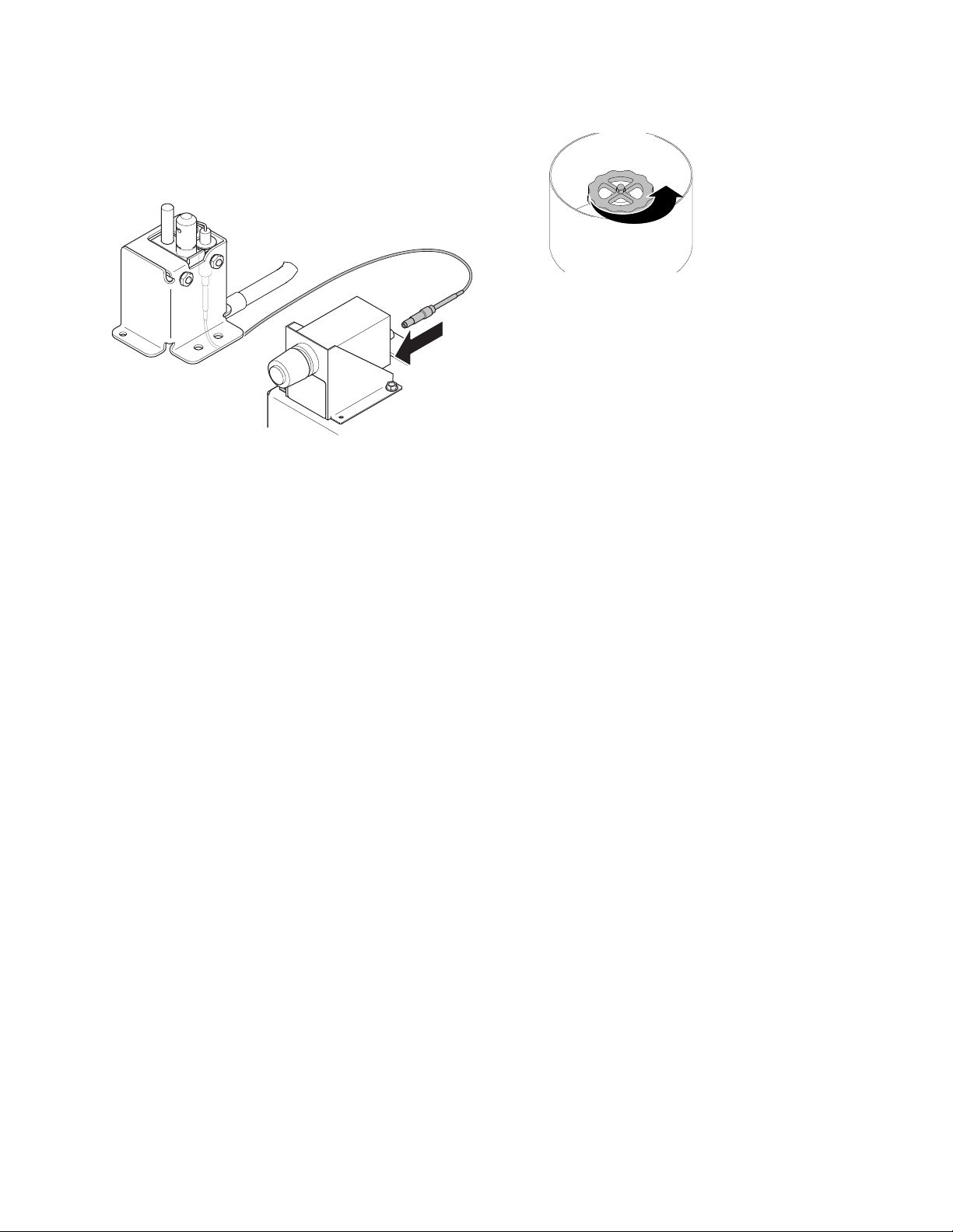
Installation
1. Replace thermopile (7).
2. Install gas pilot mounting plate (319) to gas burner
mounting plate (18). Connect ground lead wire
(244).
ThermoLazer 300TC/ProMelt
Shown
5. Guide thermopile wire into gas safety valve enclosure (28).
6. Replace wire strain relief fitting (357) on gas safety
valve enclosure (28).
7. Connect thermopile wires to gas safety valve (13).
See Wiring Diagram and Parts manual 3A1321 for
additional details.
3. Connect gas pilot line (71) to flared adapter (421).
8. Replace cover (320) on gas safety valve enclosure
(28).
ThermoLazer 300TC/ProMelt
4. Pull thermopile through wire sleeving.
14 3A1320L
9. Replace gas safety enclosure back cover (29).
Thermopile Replacement
ti25745a
ti14127a
10. ThermoLazer 300TC/ProMelt Only: Pull electrode
wire through wire sleeving.
11. ThermoLazer 300
TC/ProMelt Only: Connect elec-
trode lead to pulse fire igniter.
12. Reconnect hose and turn LP-gas tank valve ON.
13. Check for gas leaks at final assembly (see Opera-
tion manual).
3A1320L 15
 Loading...