

Graco Sharpe Finex FX1000, Sharpe Finex FX2000, Sharpe Finex FX3000 Instructions-parts List Manual
Instructions - Parts List /
Manuel d’instructions – Liste des pièces /
Instrucciones – Lista de piezas
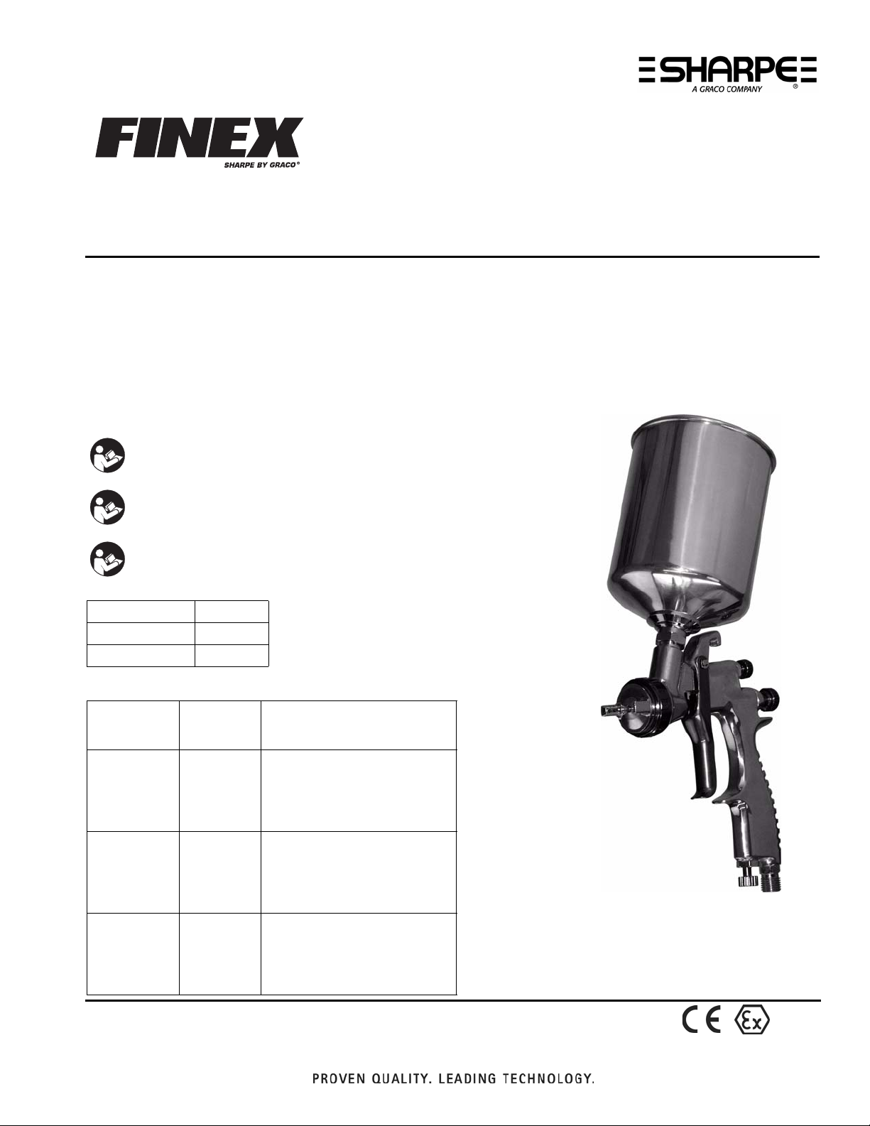
Finex™ Gravity Feed Gun
Finex
Pistola con alimentación por gravedad Finex™
For the spray application of paints and coatings. Includes Mini-HVLP, HVLP, and Conventional Models
Pour la pulvérisation de peintures et de revêtements. Comprend les modèles Mini-HVLP, HVLP, et
Conventional
Para la aplicación mediante la pulverización de pinturas y revestimientos. Incluye los modelos Mini-HVLP, HVLP,
y Convencional
100 psi (0.7 MPa, 7 bar) Maximum Working Air Pressure
Pression maximale pneumatique de service de 100 psi (0,7 MPa, 7 bars)
Presión máxima de trabajo de aire de 100 psi (0,7 MPa, 7 bar)
™
- Pistolet alimenté par gravité
Important Safety Instructions
Read all warnings and instructions in this manual.
Save these instructions.
Instructions de sécurité importantes
Lire toutes les mises en garde et instructions de ce manuel.
Sauvegarder ces instructions.
Instrucciones importantes de seguridad
Lea todas las advertencias e instrucciones de este manual.
Guarde las instrucciones.
312372E
English page 2
Français page 11
Español página 21
Models / Modèles / Modelos
Model /
Modèle /
Modelo
FX1000
Mini-HVLP
FX2000
Conventional
FX3000 HVLP
Part No. /
Pièce No. /
Ref. pieza
289198 0.6
289199 0.8
289200 1.0
289221 1.2
289222 1.4
288883 1.0
288884 1.3
288885 1.4
288886 1.5
288887 1.8
288878 1.0
288879 1.3
288880 1.4
288881 1.5
288882 1.8
Needle/Nozzle Size /
Diamètre pointeau/buse /
Tamaño de la aguja/boquilla
II 2 G
Warnings
Warnings
The following warnings are for the setup, use, grounding, maintenance, and repair of this equipment. The exclamation point symbol alerts you to a general warning and the hazard symbol refers
to procedure-specific risk. Refer back to these warnings. Additional, product-specific warnings
may be found throughout the body of this manual where applicable.
WARNING
FIRE AND EXPLOSION HAZARD
Flammable fumes, such as solvent and paint fumes, in work area can ignite or explode.
To help prevent fire and explosion:
• Use equipment only in well ventilated area.
• Eliminate all ignition sources; such as pilot lights, cigarettes, portable electric lamps,
and plastic drop cloths (potential static arc).
• Keep work area free of debris, including solvent, rags and gasoline.
• Do not plug or unplug power cords or turn lights on or off when flammable fumes are
present.
• Ground all equipment in the work area. See Grounding instructions.
• If there is static sparking or you feel a shock, stop operation immediately. Do not
use equipment until you identify and correct the problem.
• Keep a working fire extinguisher in the work area.
EQUIPMENT MISUSE HAZARD
Misuse can cause death or serious injury.
• Do not operate the unit when fatigued or under the influence of drugs or alcohol.
• Do not exceed the maximum working pressure or temperature rating of the lowest
rated system component. See Technical Data in all equipment manuals.
• Use fluids and solvents that are compatible with equipment wetted parts. See
Technical Data in all equipment manuals. Read fluid and solvent manufacturer’s
warnings. For complete information about your material, request MSDS forms from
distributor or retailer.
• Check equipment daily. Repair or replace worn or damaged parts immediately with
genuine manufacturer’s replacement parts only.
• Do not alter or modify equipment.
• Use equipment only for its intended purpose. Call your distributor for information.
• Route hoses and cables away from traffic areas, sharp edges, moving parts, and hot
surfaces.
• Do not kink or over bend hoses or use hoses to pull equipment.
• Keep children and animals away from work area.
• Comply with all applicable safety regulations.
PRESSURIZED EQUIPMENT HAZARD
Fluid from the gun/dispense valve, leaks, or ruptured components can splash in the
eyes or on skin and cause serious injury.
• Follow Pressure Relief Procedure in this manual, when you stop spraying and
before cleaning, checking, or servicing equipment.
• Tighten all fluid connections before operating the equipment.
• Check hoses, tubes, and couplings daily. Replace worn or damaged parts
immediately.
2 312372E
Setup
WARNING
TOXIC FLUID OR FUMES HAZARD
Toxic fluids or fumes can cause serious injury or death if splashed in the eyes or on
skin, inhaled, or swallowed.
• Read MSDS’s to know the specific hazards of the fluids you are using.
• Store hazardous fluid in approved containers, and dispose of it according to applicable guidelines.
• Always wear impervious gloves when spraying or cleaning equipment.
PERSONAL PROTECTIVE EQUIPMENT
You must wear appropriate protective equipment when operating, servicing, or when in
the operating area of the equipment to help protect you from serious injury, including
eye injury, inhalation of toxic fumes, burns, and hearing loss. This equipment includes
but is not limited to:
• Protective eyewear
• Clothing and respirator as recommended by the fluid and solvent manufacturer
• Gloves
• Hearing protection
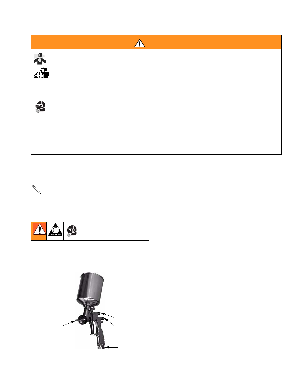
Setup
Reference numbers and letters in parentheses in the text refer to numbers and
letters in the illustrations.
1. Install an air pressure regulator on gun air
supply line to control air pressure.
2. Install a shutoff valve downstream of the air
regulator to shut off gun air.
3. Connect a clean, dry, filtered air supply to
air inlet fitting (13). Connect other end to
shutoff valve.
4. Install fluid filter into fluid inlet.
5. Screw on gravity cup.
6. Remove gravity cup cover and fill cup with
solvent to flush if this is first time using
equipment. (See Flushing, page 5.)
7. After flushing, fill cup with fluid and attach
cover.
5
1
FIG. 1
312372E 3
8-2
13
Operation
Operation
Pressure Relief Procedure
1. Turn off gun air supply.
2. Hold a metal part of the gun firmly to a
grounded metal pail. Trigger gun to relieve
pressure.
Adjust Spray Pattern
Do not exceed maximum working air pressure
shown on front cover. Read warnings.
1. Rotate air cap (1) to change spray pattern
direction.
2. For maximum fluid flow and to prevent
premature fluid nozzle wear, turn fluid
adjustment knob (8-2) counterclockwise
until no trigger restriction is felt. Then turn
knob out 1/2 turn more.
3. If further fluid flow restriction is needed,
use different size needle/nozzle/air cap
combination.
a. If pattern is too wide, turn pattern
adjustment knob (5) clockwise to
narrow pattern.
b. To create a round pattern, turn pattern
adjustment knob (5) fully clockwise.
c. If pattern is too narrow, turn knob (5)
counterclockwise.
d. Check atomization. Increase gun air
supply pressure in 5 psi (34 kPa,
0.3 bar) increments until you have
the desired atomization.
Applying Paint
For the best results:
• Keep gun perpendicular to surface and
consistent distance of about 6-8 inches
(150-200 mm). Do not angle the gun as you
spray.
• Use smooth, even strokes, with about 50%
overlap.
• Mini-HVLP and HVLP Guns: Use a slightly
slower hand movement and make fewer
passes than you would with a conventional
air spray gun. Take care to avoid runs or
sags.
If necessary, fluid adjustment knob (8-2)
can be turned clockwise to reduce volume
of fluid output. However, continuously
spraying with fluid adjustment knob closed
causes accelerated abrasive wear on fluid
needle and trigger/air valve shaft interface.
If fluid adjustment knob (8-2) is turned in
all the way, the gun emits only air.
4. Test spray pattern and atomization
while holding gun about 6 to 8 inches
(150 to 200 mm) from test piece.
4 312372E

Maintenance
Maintenance
Flushing
Flush before changing colors, before fluid can
dry in the equipment, at the end of the day,
before storing, and before repairing equipment. Use solvent that is compatible with gun
wetted parts and fluid that will be sprayed.
1. Follow Pressure Relief Procedure,
page 4.
2. Dispose of any paint in the cup.
3. Fill the cup with a small amount of solvent.
4. Spray into a grounded metal waste container until clean solvent dispenses.
4. Flush gun before changing colors and
when you are done spraying.
5. Remove cup and filter and clean them.
6. Remove air cap (1) and nozzle (2) as
instructed on page 7 and soak them in
compatible solvent.
CAUTION
Trigger gun and use gun tool (27) whenever
you tighten or remove nozzle (2) to avoid
damaging needle seat and nozzle.
7. Use a rag moistened in solvent to wipe
down outside of gun.
8. Before reinstalling air cap and nozzle, clean
them and front of gun with a soft-bristle
brush dipped into compatible solvent. Do
not use a wire brush or metal tools. To
clean out air cap holes, use a soft implement, such as a toothpick.
5. Follow Pressure Relief Procedure,
page 4.
Daily Cleaning
CAUTION
• Do not submerge gun in solvent. Solvent
dissolves lubricant, dries out packings, and
may clog air passages. You can immerse
front end of gun in solvent just until cup
connection is covered.
• Do not use metal tools to clean air cap
holes as this may scratch them and distort
the spray pattern.
• Use a compatible solvent.
1. Follow Pressure Relief Procedure,
page 4.
2. Clean fluid and air line filters.
9. Lubricate gun.
3. Check for fluid leakage from gun and fluid
hoses. Tighten fittings or replace equipment as needed.
312372E 5
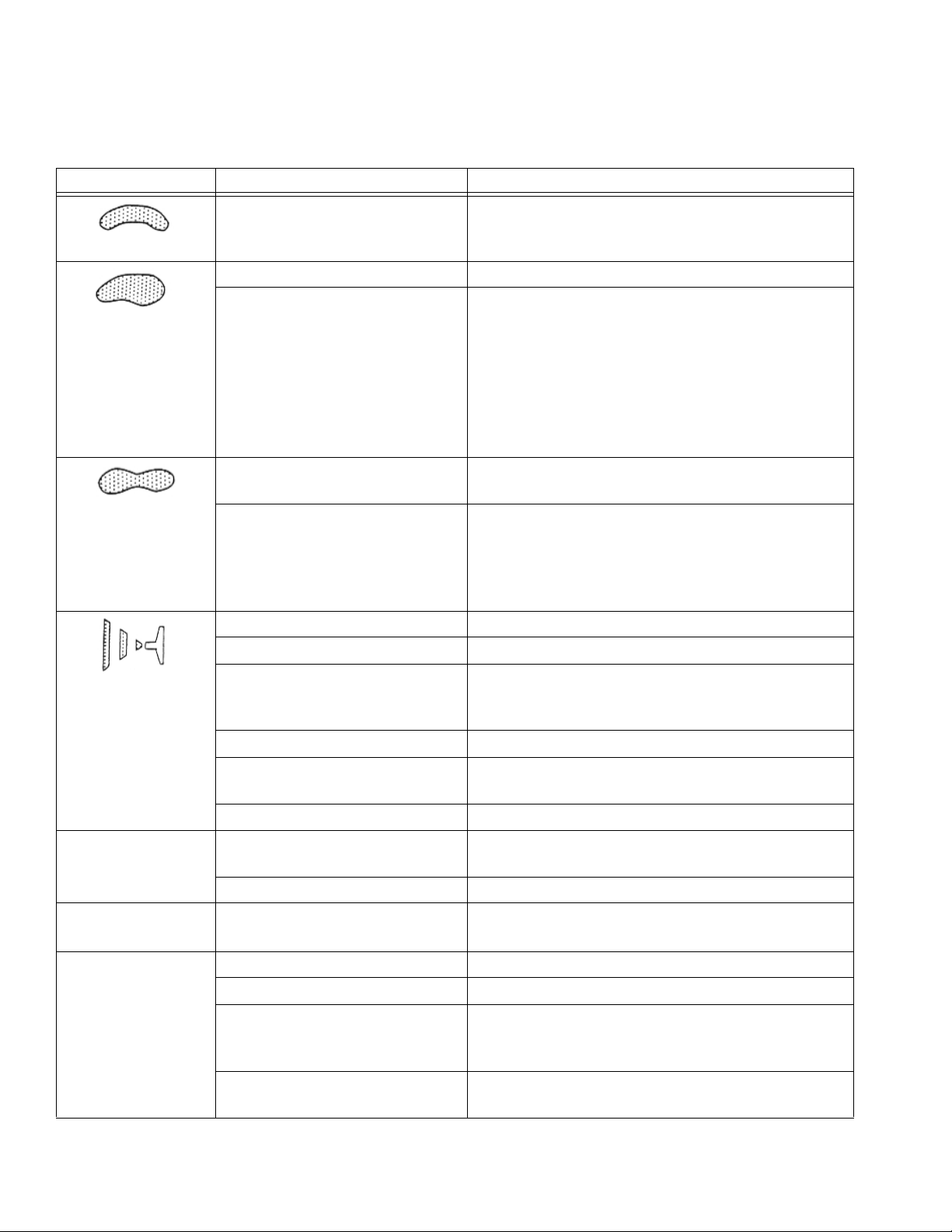
Troubleshooting
Troubleshooting
Problem Cause Solution
One side of air cap (1) dirty
or clogged.
a. Loose air cap (1). a. Tighten.
b. Dried or damaged air cap
(1) or fluid nozzle (2).
a. Atomization air pressure
set too high.
b. Spraying a thin material
in too wide of a pattern.
Air getting into paint stream.
a. Cup almost empty. a. Fill cup.
Clean air cap orifices. See page 5. Blow air
through orifices until clean. If air cap holes are
damaged, replace air cap.
b. Rotate air cap 180°.
If pattern follows air cap, problem is in air
cap. Clean and inspect. See page 5. If
pattern is not corrected, replace air cap.
If pattern does not follow the air cap, the
problem is with the fluid nozzle. Clean and
inspect the nozzle. See page 5. If the pattern is not corrected, replace nozzle.
a. Reduce air pressure.
b. Increase material control by turning fluid
adjustment knob (8-2) counterclockwise,
while reducing spray width by turning pattern adjustment knob (5) clockwise.
Or increase material viscosity.
Spitting
b. Dry needle packing (3-1
or 3-2).
b. Loosen packing nut and put a few drops of
machine oil on packings (3-1 and 3-2).
Retighten nut (4).
c. Fluid nozzle (2) too loose. c. Tighten.
d. Dried material between
nozzle (2) and gun body.
d. Clean nozzle and front of gun. See page
5.
e. Damaged needle seal. e. Replace seal. See page 7.
Other spray
pattern problems.
a. Gun not properly
adjusted.
a. See page 4.
b. Sluggish needle (10). b. Clean and lubricate.
Unable to get
round pattern.
Pattern adjustment knob (5)
not seating properly.
Clean or replace knob.
Will not spray. a. No air pressure at gun. a. Check air supply and air lines.
b. Cup empty. b. Fill cup.
c. Fluid adjustment knob
c. Adjust knob (8-2) counterclockwise.
(8-2) turned too far
clockwise.
d. Fluid too thick for gravity
d. Thin material.
feed.
6 312372E
Problem Cause Solution
Fluid leaking from
packing nut (4).
Fluid nozzle (2)
dripping.
a. Packing nut (4) loose. a. Tighten, but not so tight as to grip needle.
b. Packing (3-1 or 3-2) worn
or dry.
a. Dry packing (3-1 or 3-2). a. Lubricate.
b. Sluggish needle (10). b. Clean and lubricate.
c. Packing nut (4) too tight. c. Loosen.
b. Lubricate or replace.
Service
d. Worn fluid nozzle or
needle.
Thin, coarse
finish.
Thick, dimpled
finish (resembling
orange peel).
a. Gun held too far from
surface.
b. Atomization air pressure
set too high.
Gun held too close to
surface.
Service
Preparation
1. Flush and clean gun before servicing.
d. Replace.
a. Hold gun about 6-8 inches (150-200 mm)
from surface.
b. Reduce air pressure.
Hold gun about 6-8 inches (150-200 mm)
from surface.
Air Valve and Needle Packings
1. Remove retaining rings (15), pin (16), and
trigger (17).
2. Remove packing nut (4) and fluid needle
packings (3-1 and 3-2).
3. Remove fluid needle guide (7).
4. Remove fluid adjusting guide (8-1).
2. Follow Pressure Relief Procedure, see
page 4.
Air Cap, Nozzle, and Needle
1. Unscrew air cap (1).
2. Trigger gun while you remove the nozzle
(2) with gun tool (27).
Trigger gun and use gun tool (27) whenever you tighten or remove the nozzle (2)
to avoid damage.
3. Remove fluid adjustment knob (8-2) and
spring (9).
4. Pull needle (10) out of the back of the gun.
312372E 7
5. Remove spring (18) and air valve (19).
6. Remove air valve seat (20) and o-ring.
7. Replace parts as needed.
8. Assemble gun in reverse order. Lubricate
needle and o-rings. Be sure to trigger gun
when installing nozzle (2).
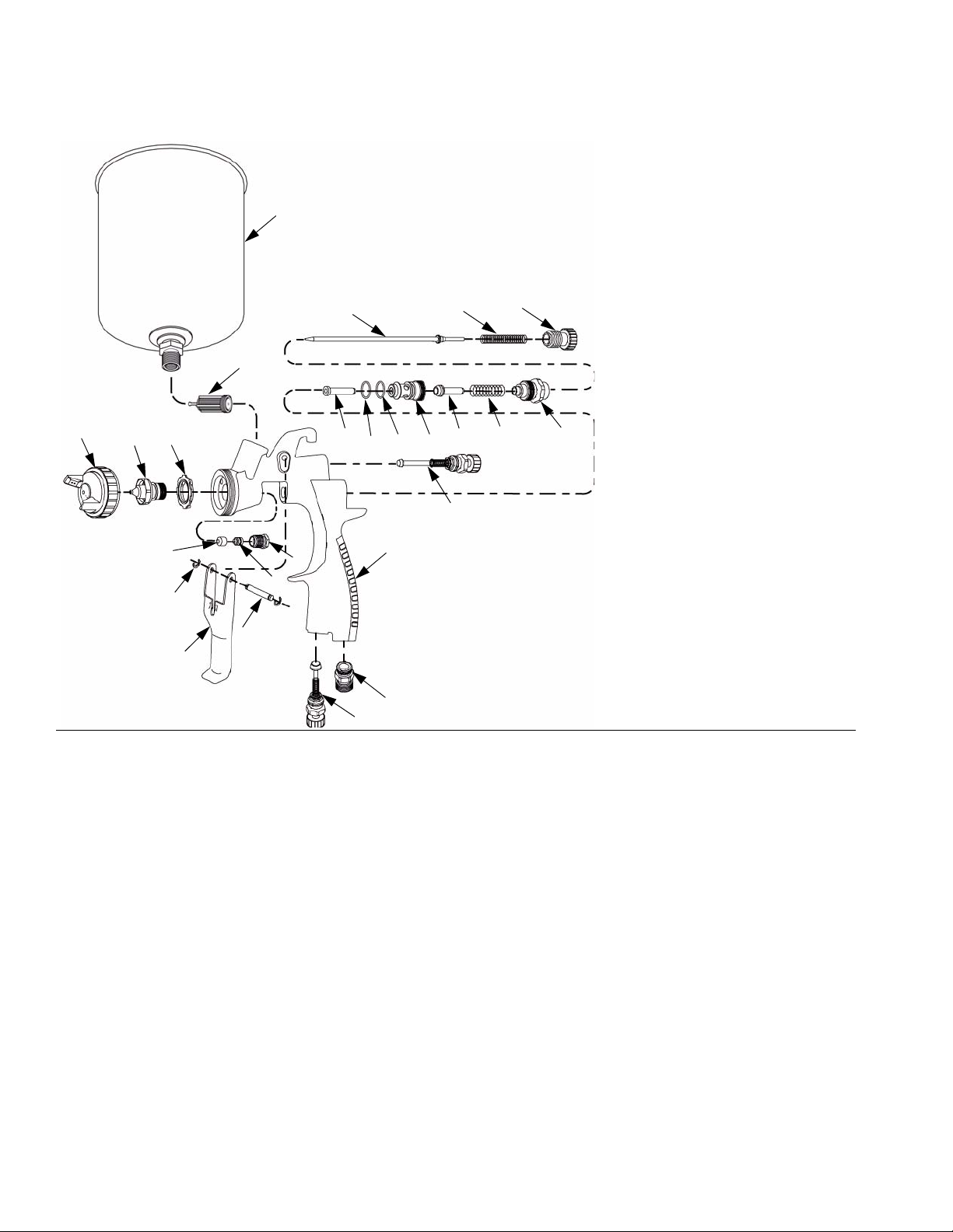
Parts
Parts
1
Ref. Description Qty
1 CAP, air 1
2 NOZZLE, fluid 1
26
3-1* PACKING, fluid needle 1
3-2* PACKING, fluid needle 1
4* NUT, packing 1
5* KNOB, pattern
1
adjustment
10
8-29
6* O-RING 1
7* GUIDE, fluid needle 1
8-1* GUIDE, fluid adjusting 1
24
8-2* KNOB, fluid adjusting 1
9* SPRING, fluid needle 1
10 NEEDLE, fluid 1
11* O-RING 1
12-2
2
7
11
6
20
19
18
8-1
12-1 BODY, gun 1
12-2*DISTRIBUTOR, air 1
13* FITTING, air inlet 1
14* VALVE, air adjustment 1
5
15* RING, retaining 2
16* PIN, trigger 1
3-1
15
3-2
4
12-1
17* TRIGGER 1
18* SPRING, air valve 1
19* VALVE, air 1
20* SEAT, air valve 1
24* FILTER, fluid 1
16
17
26 CUP, gravity, aluminum 1
27 TOOL, gun (not shown) 1
14
13
ti10444a
8 312372E
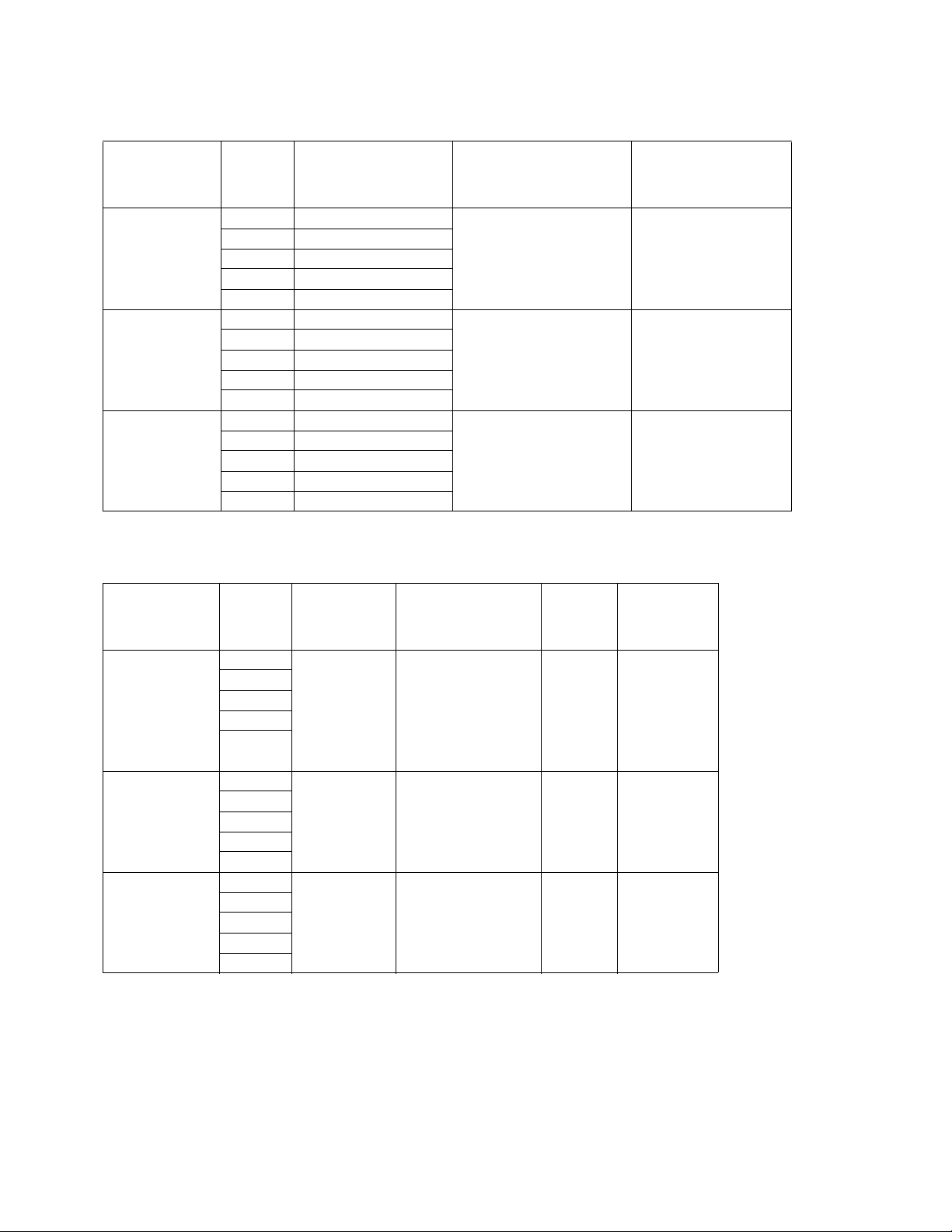
Repair Kits
Repair Kits
Model
FX 1000
Mini-HVLP
FX 2000
Conventional
FX 3000
HVLP
Needle/
Nozzle
Size
0.6 289286
0.8 289287
1.0 289288
1.2 289289
1.4 289290
1.0 289291
1.3 289292
1.4 289293
1.5 289294
1.8 289295
1.0 289296
1.3 289297
1.4 289298
1.5 289299
1.8 289300
Needle, Nozzle, Air
(Parts 1, 2, and 10)
Accessory Kits
Needle/
Model
FX 1000
Mini-HVLP
FX 2000
Conventional
FX 3000
HVLP
Nozzle
Size
0.6 289517
0.8
1.0
1.2
1.4
1.0
1.3
1.4
1.5
1.8
1.0
1.3
1.4
1.5
1.8
Gravity Cup
(aluminum)
(125 cc)
Standard
(250 cc)
(600 cc)
(600 cc)
289321
289320
289320
Cap Kit
Gravity Cup Lid
Needle Packing Kit
(parts 3-1, 3-2, and 4)
(Plastic)
289816
(125 cc)
289817
(250 cc)
289818
(600 cc)
289818
(600 cc)
Gun Rebuild Kit
(includes parts
marked *)
288890 288895
288891 288896
288891 288896
PPS
Adapter
289520 24A230
289520 24A230
289520 24A230
Fluid Filter
(pack of 10)
312372E 9

Technical Data
Technical Data
Maximum Air Inlet Pressure 100 psi (0.7 MPa, 7 bar)
Maximum HVLP Inbound Air Pressure 29 psi (0.2 MPa, 2 bar)*
Air Consumption
FX1000
FX2000
FX3000
Fluid and Air Operating Temperature Range 32-109°F (0-43° C)
Spray Gun
Air Inlet Size
FX1000 Weight with cup
FX2000/3000 Weight with cup
Wetted Parts Aluminum, stainless steel, engineered
Noise Data**
FX1000 sound pressure at 29 psi (0.2 MPa, 2.0 bar)
sound power at 29 psi (0.2 MPa, 2.0 bar)
FX2000 sound pressure at 43 psi (0.3 MPa, 3.0 bar)
sound power at 43 psi (0.3 MPa, 3.0 bar)
FX3000 sound pressure at 29 psi (0.2 MPa, 2.0 bar)
sound power at 29 psi (0.2 MPa, 2.0 bar)
Gravity Cup Sizes
FX1000 aluminum
FX 2000/3000 aluminum
7.0 SCFM at 29 psi (0.2 MPa, 2.0 bar)
9.5 SCFM at 43 psi (0.3 MPa, 3.0 bar)
9.5 SCFM at 29 psi (0.2 MPa, 2.0 bar)
1/4 npsm (R1/4-19)
0.9 lb (0.4 kg)
1.1 lb (0.5 kg)
plastic
78.17 dB(A)
85.32 dB(A)
81.91 dB(A)
89.23 dB(A)
80.60 dB(A)
87.74 dB(A)
4 oz (125 cc); 8 oz (250 cc)
20 oz (600 cc)
* Produces 10 psi (0.07 MPa, 0.7 bar) spraying pressure at aircap.
** All readings were taken with the fan valve fully open (fan full size) at the assumed operator
position. Sound power measured per ISO 9614-2.
10 312372E
 Loading...