

Page 1
3A6673B
EN
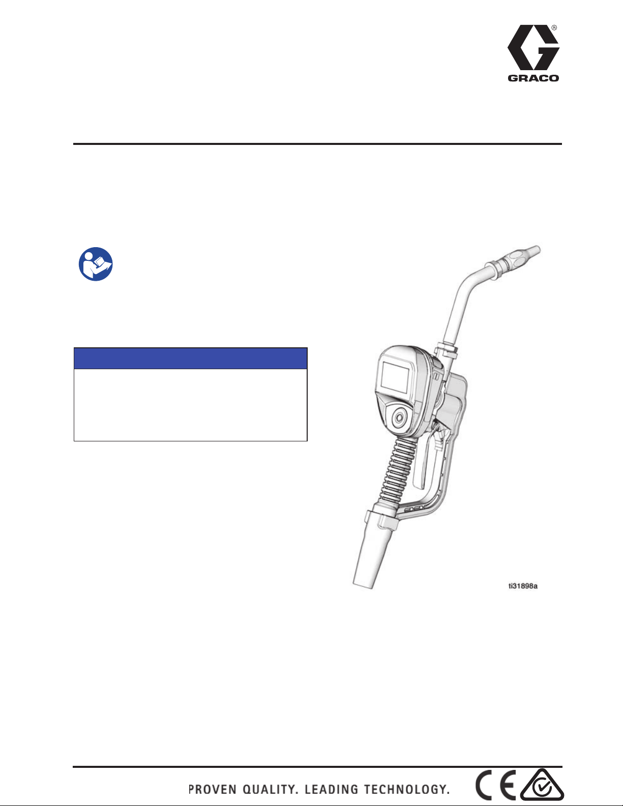
Installation and Operation
SDP8/SDP18 Preset
Metered Dispense Valve
Pulse FC Enabled
For dispensing oil, automatic transmission fluid (ATF), gear oils, and antifreeze.
Not approved for use in explosive atmospheres or hazardous locations. For professional
use only.
See page 6 for model information.
1500 psi (10 MPa, 103 bar) Maximum Working Pressure
Important Safety
Instructions
Read all warnings and instructions
in this manual and related system
manuals before using the
equipment. Save all instructions.
NOTICE
The metered dispense valve is designed to
dispense petroleum-based lubricants, and
antifreeze only. Brake cleaner and/or harsh
solvents may damage the plastic
components.
Page 2

Contents
Contents
Warnings ....................................................................................................4
Models ........................................................................................................6
Overview ....................................................................................................7
Metered Dispense Valve .......................................................................7
Navigation Pad (F
Locking and Unlocking the Trigger .......................................................7
Opening and Closing the Nozzle ..........................................................8
Typical Installation ....................................................................................9
Mounting Bracket ..................................................................................9
Oil Bar ...................................................................................................9
Installation ...............................................................................................10
Pressure Relief Procedure ..................................................................10
Grounding ...........................................................................................10
Pre-Installation Procedure ..................................................................10
Flushing ..............................................................................................11
Install the Metered Dispense Valve ....................................................11
Install the Extension Tube ..................................................................12
Install the Nozzle ................................................................................12
Preset Mode .............................................................................................13
Main Menu Screen ..............................................................................13
Calibration ...........................................................................................13
IG. 1) .........................................................................7
Manual Calibration . . . . . . . . . . . . . . . . . . . . . . . . . . . . . . . . . . . .15
Alternate Calibration . . . . . . . . . . . . . . . . . . . . . . . . . . . . . . . . . . .16
DISPENSE ..........................................................................................18
Preset Dispense . . . . . . . . . . . . . . . . . . . . . . . . . . . . . . . . . . . . . .19
TOTAL ................................................................................................21
UTILITY MENU ...................................................................................21
DEVICE INFORMATION . . . . . . . . . . . . . . . . . . . . . . . . . . . . . . .21
RESET . . . . . . . . . . . . . . . . . . . . . . . . . . . . . . . . . . . . . . . . . . . . .22
SET-UP SCREENS . . . . . . . . . . . . . . . . . . . . . . . . . . . . . . . . . . .22
DEVICE INFORMATION . . . . . . . . . . . . . . . . . . . . . . . . . . . . . . .27
RESET . . . . . . . . . . . . . . . . . . . . . . . . . . . . . . . . . . . . . . . . . . . . .27
GO BACK . . . . . . . . . . . . . . . . . . . . . . . . . . . . . . . . . . . . . . . . . . .27
2 3A6673B
Page 3

Contents
Pulse FC Mode ........................................................................................28
Enable Pulse FC Mode .......................................................................28
Activation ............................................................................................29
Calibration ..........................................................................................29
Manual Calibration . . . . . . . . . . . . . . . . . . . . . . . . . . . . . . . . . . . 30
DISPENSE .........................................................................................31
Screen Identification . . . . . . . . . . . . . . . . . . . . . . . . . . . . . . . . . . 31
UTILITY MENU ...................................................................................33
Service ..................................................................................................... 35
Battery Replacement ..........................................................................35
Parts ......................................................................................................... 36
Parts ......................................................................................................... 37
Related Kits ........................................................................................ 37
Troubleshooting ...................................................................................... 38
Error Codes .............................................................................................40
Technical Specifications ........................................................................ 41
FCC / IC Notice . . . . . . . . . . . . . . . . . . . . . . . . . . . . . . . . . . . . . . 42
Graco 5-Year Meter and Valve Warranty ............................................... 43
3A6673B 3
Page 4
Warnings
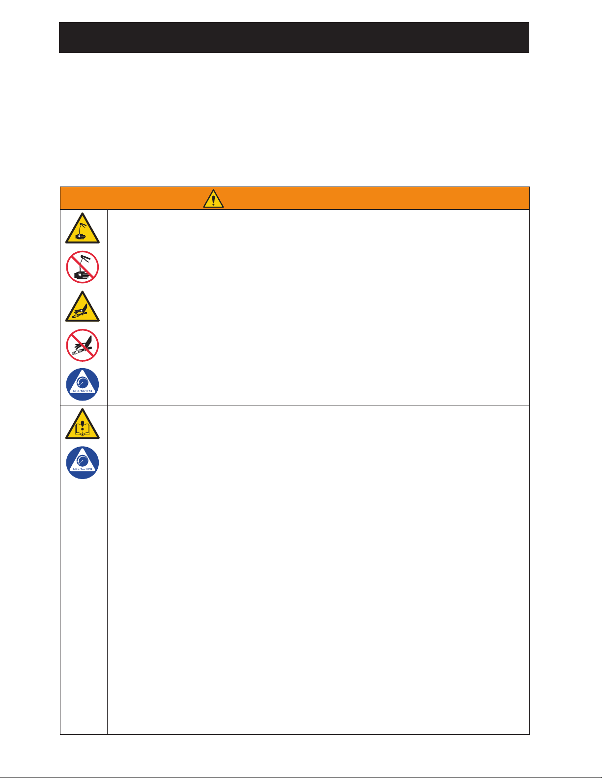
WARNING
SKIN INJECTION HAZARD
High-pressure fluid from dispensing device, hose leaks, or ruptured components
will pierce skin. This may look like just a cut, but it is a serious injury that can result
in amputation. Get immediate surgical treatment.
• Do not point dispensing device at anyone or at any part of the body.
• Do not put your hand over the fluid outlet.
• Do not stop or deflect leaks with your hand, body, glove, or rag.
• Follow the Pressure Relief Procedure when you stop dispensing and before
cleaning, checking, or servicing equipment.
• Tighten all fluid connections before operating the equipment.
• Check hoses and couplings daily. Replace worn or damaged parts immediately.
EQUIPMENT MISUSE HAZARD
Misuse can cause death or serious injury.
• Do not operate the unit when fatigued or under the influence of drugs or alcohol.
• Do not exceed the maximum working pressure or temperature rating of the low-
est rated system component. See Technical Specifications in all equipment
manuals.
• Use fluids and solvents that are compatible with equipment wetted parts. See
Technical Specifications in all equipment manuals. Read fluid and solvent
manufacturer’s warnings. For complete information about your material, request
Safety Data Sheets (SDSs) from distributor or retailer.
• Turn off all equipment and follow the Pressure Relief Procedure when equip-
ment is not in use.
• Check equipment daily. Repair or replace worn or damaged parts immediately
with genuine manufacturer’s replacement parts only.
• Do not alter or modify equipment. Alterations or modifications may void agency
approvals and create safety hazards.
• Make sure all equipment is rated and approved for the environment in which you
are using it.
• Use equipment only for its intended purpose. Call your distributor for information.
• Route hoses and cables away from traffic areas, sharp edges, moving parts, and
hot surfaces.
• Do not kink or over bend hoses or use hoses to pull equipment.
• Keep children and animals away from work area.
• Comply with all applicable safety regulations.
Warnings
The following warnings are for the setup, use, grounding, maintenance, and repair of this
equipment. The exclamation point symbol alerts you to a general warning and the hazard
symbols refer to procedure-specific risks. When these symbols appear in the body of this
manual or on warning labels, refer back to these Warnings. Product-specific hazard symbols
and warnings not covered in this section may appear throughout the body of this manual where
applicable.
4 3A6673B
Page 5
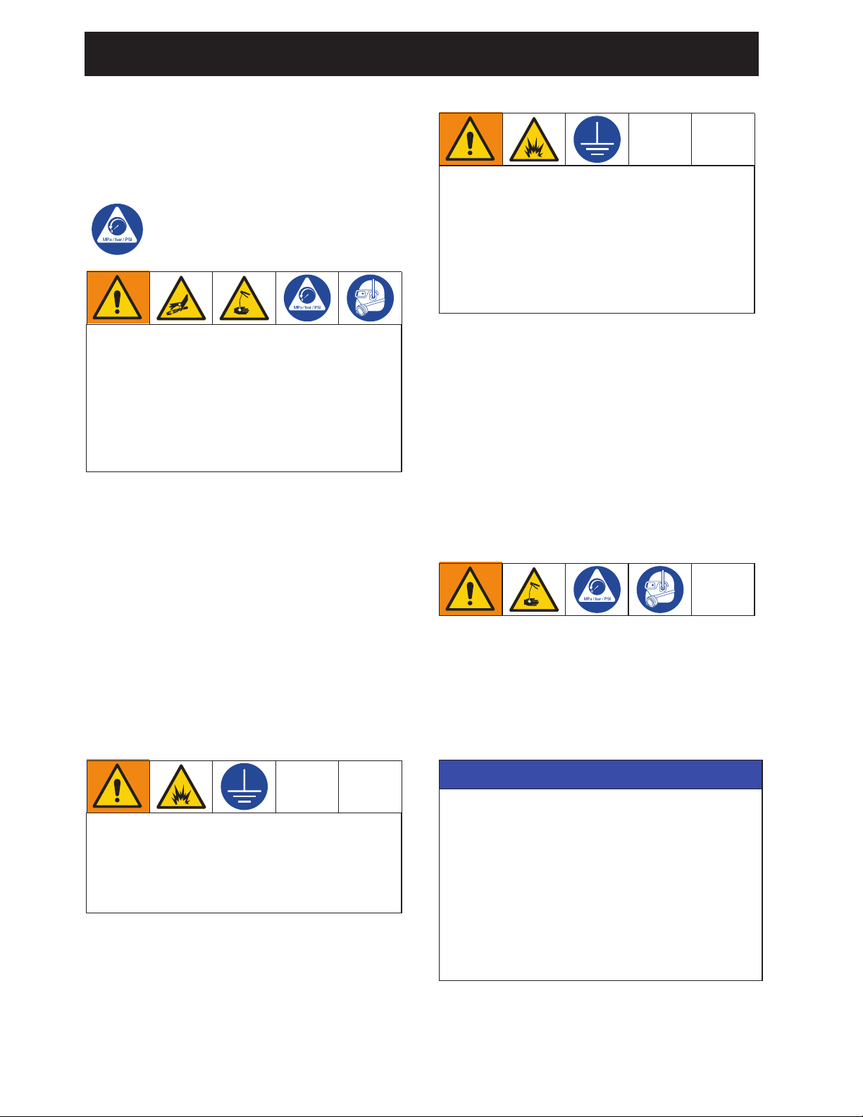
Warnings
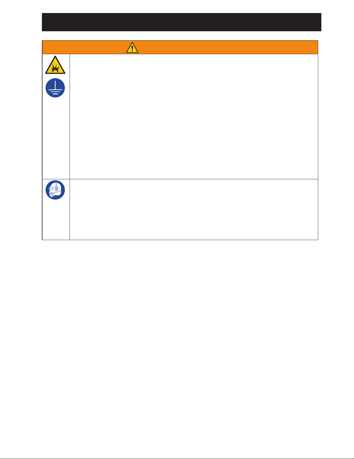
FIRE AND EXPLOSION HAZARD
When flammable fluids are present in the work area, such as gasoline and windshield wiper fluid, be aware that flammable fumes can ignite or explode. To help
prevent fire and explosion:
• Use equipment only in well-ventilated area.
• Eliminate all ignition sources, such as cigarettes and portable electric lamps.
• Ground all equipment in the work area.
• Keep work area free of debris, including rags and spilled or open containers of
solvent and gasoline.
• Do not plug or unplug power cords or turn lights on or off when flammable fumes
are present.
• Use only grounded hoses.
• Stop operation immediately if static sparking occurs or you feel a shock. Do
not use equipment until you identify and correct the problem.
• Keep a working fire extinguisher in the work area.
PERSONAL PROTECTIVE EQUIPMENT
Wear appropriate protective equipment when in the work area to help prevent serious injury, including eye injury, hearing loss, inhalation of toxic fumes, and burns.
Protective equipment includes but is not limited to:
• Protective eye wear, and hearing protection.
• Respirators, protective clothing, and gloves as recommended by the fluid and
solvent manufacturer.
WARNING
3A6673B 5
Page 6
Models
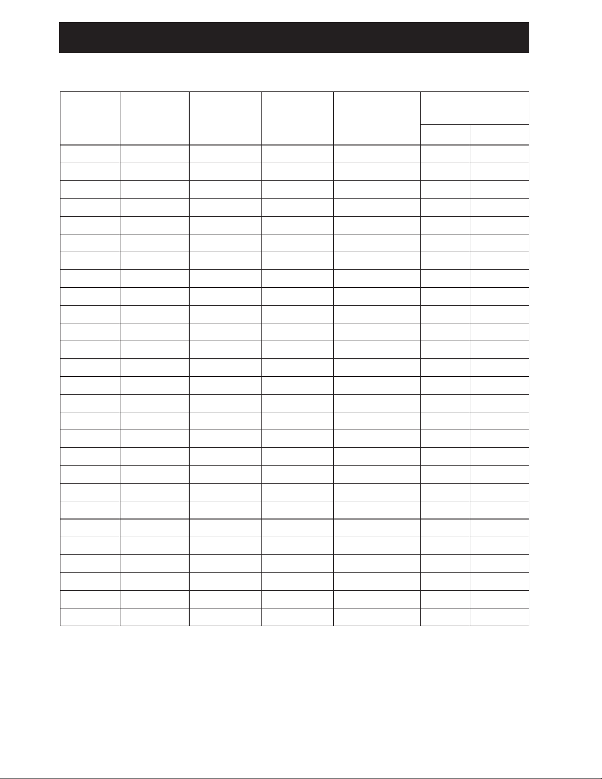
Models
Max Volumetric
Flow Rate
Model Swivel Extension Nozzle Fluid
26C384 1/2 NPT Rigid Automatic Oil 8 30
26C385 1/2 NPT Rigid Antifreeze Antifreeze 8 30
26C354 1/2 NPT Flexible Automatic Oil 8 30
26C355 1/2 NPT Flexible Antifreeze Antifreeze 8 30
26C356 1/2 NPT Rigid High Flow Oil 18 68
26C357 1/2 NPT Flexible High Flow Oil 18 68
26C358 1/2 NPT Gear Lube Manual Gear Lube 5 19
26C360 3/4 NPT Rigid High Flow Oil 18 68
26C361 3/4 NPT Flexible High Flow Oil 18 68
26C362 1/2 BSPP Rigid Automatic Oil 8 30
26C363 1/2 BSPP Rigid Antifreeze Antifreeze 8 30
26C364 1/2 BSPP Flexible Automatic Oil 8 30
26C365 1/2 BSPP Flexible Antifreeze Antifreeze 8 30
26C368 1/2 BSPP Rigid High Flow Oil 18 68
26C369 1/2 BSPP Flexible High Flow Oil 18 68
GPM
LPM
26C370 1/2 BSPP Gear Lube Manual Gear Lube 5 19
26C372 3/4 BSPP Rigid High Flow Oil 18 68
26C373 3/4 BSPP Flexible High Flow Oil 18 68
26C374 1/2 BSPT Rigid Automatic Oil 8 30
26C375 1/2 BSPT Rigid Antifreeze Antifreeze 8 30
26C376 1/2 BSPT Flexible Automatic Oil 8 30
26C377 1/2 BSPT Flexible Antifreeze Antifreeze 8 30
26C378 1/2 BSPT Rigid High Flow Oil 18 68
26C379 1/2 BSPT Flexible High Flow Oil 18 68
26C380 1/2 BSPT Gear Lube Manual Gear Lube 5 19
26C382 3/4 BSPT Rigid High Flow Oil 18 68
26C383 3/4 BSPT Flexible High Flow Oil 18 68
6 3A6673B
Page 7
Overview
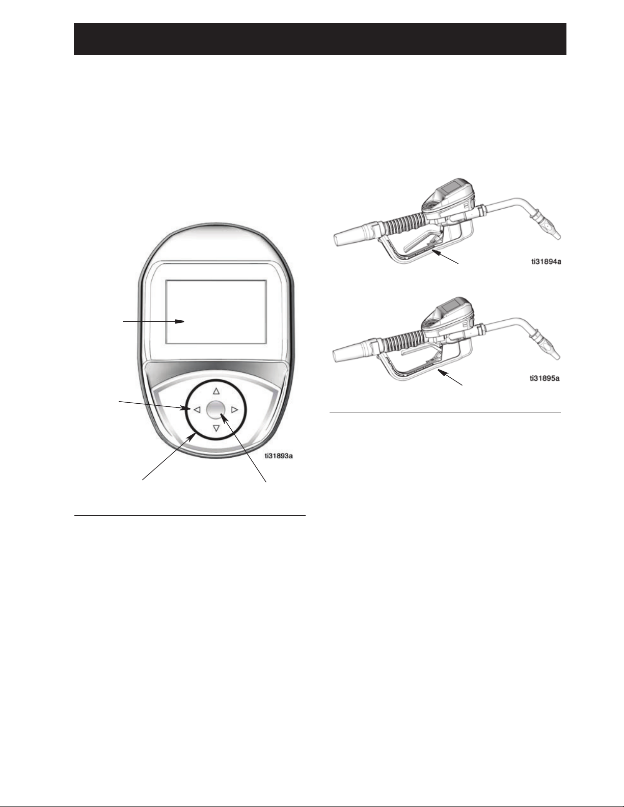
Navigation Pad
ENTER
Display
Navigation
Arrows
FIG. 2
Unlocked
Locked
Overview
Metered Dispense Valve
NOTE: The metered dispense valve can be
set up to be used without a Pulse FC system,
or with a Pulse FC system with the installation
of a Pulse FC Starter kit (P/N 26C401).
Locking and Unlocking
the Trigger
FIG. 1
Navigation Pad (FIG. 1)
The Navigation Pad includes 4 navigation
ARROWS (UP, DOWN, LEFT, RIGHT) and a
center, ENTER button.
Arrows: Move the cursor on the display.
ENTER button: Used to select or store an
entry.
The locking trigger feature locks the trigger in
the dispense position as shown in FIG. 2. To
release the lock, firmly squeeze the trigger to
the handle.
NOTE: Do no leave the metered dispense
valve unattended during a dispense.
3A6673B 7
Page 8
Overview
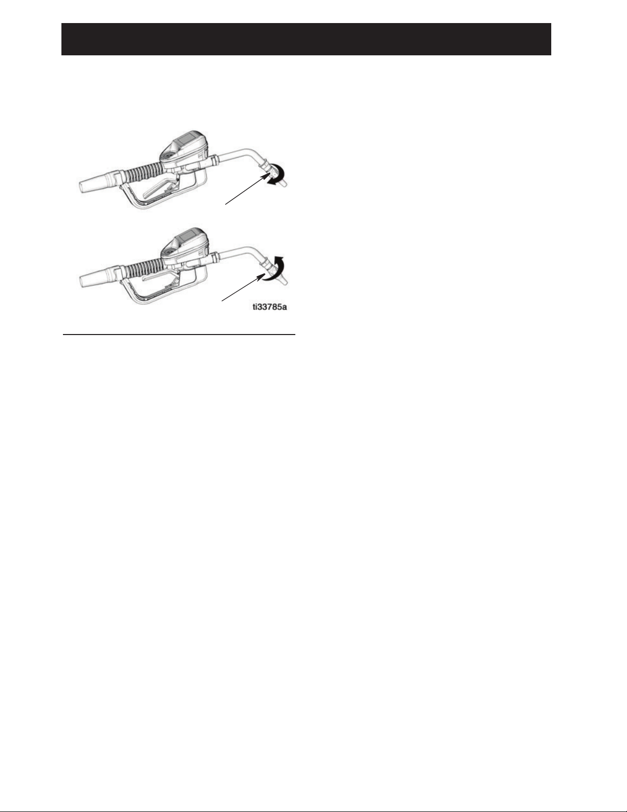
Open
Closed
Opening and Closing the
Nozzle
FIG. 3
• To open the nozzle, rotate the nozzle
clockwise.
• To close the nozzle, rotate the nozzle
counter-clockwise.
8 3A6673B
Page 9
Typical Installation
E
A
C
D
B
FIG. 5
FIG. 6
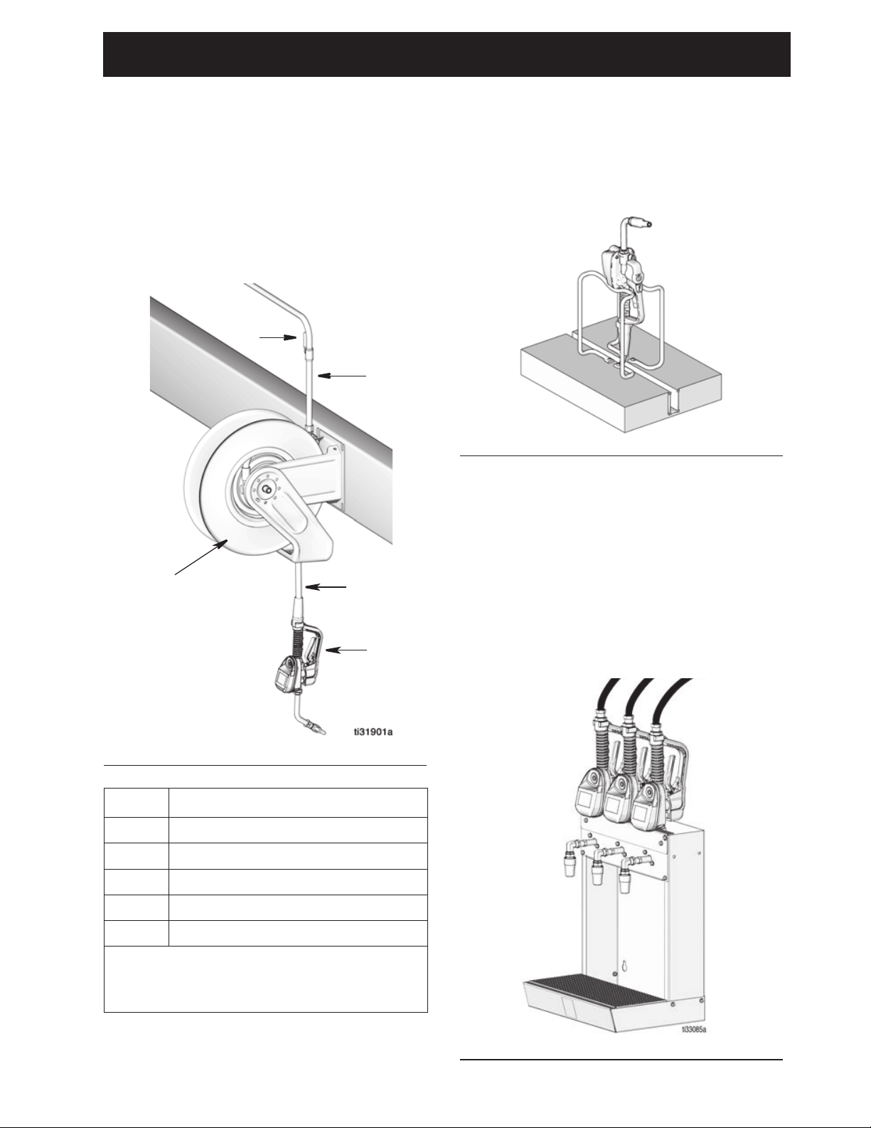
Typical Installation
The typical installation shown in FIG. 4 is only
a guide. It is not a complete system design.
Contact your Graco distributor for assistance
in designing a system to suit your needs.
The metered dispense valve is not designed
for in-line installation.
Mounting Bracket
Mounting Bracket Kit 249440 is available for
mounting the metered dispense valve on a
console.
Oil Bar
FIG. 4
Ref Description
A Metered dispense valve
B Fluid shut-off valve
C Hose
D Hose reel fluid inlet hose
E Hose reel
An Oil Bar Kit is available for mounting one to
three metered dispense valves. Contact your
Graco Distributor for ordering details.
NOTE: The Utility Menu provides an option to
flip the metered dispense valve display for
easy viewing when the metered dispense
valve is installed in the Oil Bar.
A Thermal Relief Kit (not shown) is
required. The kit required will vary by pump
selected.
3A6673B 9
Page 10
Installation
10 3A6673B
Installation
Pressure Relief Procedure
Follow the Pressure Relief
Procedure whenever you see this
symbol.
1. Turn off the power supply to the pump or
close the fluid shut off valve (B).
2. Open the nozzle. Authorize and activate
a dispense. Trigger the metered
dispense valve into a waste container to
relieve pressure.
3. Open any bleed-type master air valves
and fluid drain valves in the system.
4. Leave the drain valve open until ready to
pressurize the system.
Grounding
Follow manufacturer’s recommendations to
ground the pump and fluid supply
container.
Ground the hose and reel or console. Leave
at least two threads bare when using PTFE
tape. The bare threads ensure a ground is
maintained.
To maintain grounding continuity when
flushing or relieving pressure: hold a metal
part of the metered dispense valve firmly to
the side of a grounded metal pail, then trigger
the metered dispense valve.
Hoses: Only use electrically conductive
hoses. Check electrical resistance of hoses.
If total resistance to ground exceeds 29
megohms, replace the hose immediately.
Pre-Installation Procedure
1. See Relieve pressure, page 10.
2. Close fluid shut-off valve (B, FIG. 4, page
9).
3. Ground the hose and reel or console
(see Grounding, page 10).
4. Flush equipment. See Flushing, page
11.
This equipment stays pressurized until
pressure is manually relieved. To help
prevent serious injury from pressurized
fluid, such as skin injection, splashing fluid
and moving parts, follow the Pressure
Relief Procedure when you stop
dispensing and before cleaning, checking,
or servicing the equipment.
The equipment must be grounded to
reduce the risk of static sparking. Static
sparking can cause fumes to ignite or
explode. Grounding provides an escape
wire for the electric current.
FIRE HAZARD
Conductive metal surfaces on the metered
dispense valve must not make contact with
any positively charged metal surface,
including (but not limited to), the starter
solenoid terminal, alternator terminal or
battery terminal. Such contact could cause
electrical arcing and a fire.
NOTICE
• If this is a new installation or if the fluid
lines are contaminated, flush the lines
before installing the metered dispense
valve. Contaminated lines could cause
the metered dispense valve to leak.
• Never dispense compressed air with
metered dispense valve. Dispensing
compressed air will damage the
metered dispense valve.
Page 11
Installation
FIG. 7
b
6
a
Flushing
The equipment was tested with lightweight
oil, which was left in the fluid passages to
protect parts. To avoid contaminating the
fluid, flush the equipment with a compatible
solvent before use.
1. Close the fluid shut-off valve (B, FIG. 4,
page 9) at each dispense position.
2. Make sure:
• the main fluid outlet valve at the
pump is closed.
• the air pressure to the pump motor
is adjusted to minimize the system
flow rate without the metered
dispense valve attached.
• the air valve is open.
3. Slowly open the main fluid outlet valve.
a. Place the hose end (with no
metered dispense valve connected)
into a container for waste oil.
b. Secure the hose in the container to
avoid it becoming loose during
flushing.
c. For multiple dispense positions, first
flush the dispense position farthest
from the pump then work toward the
pump.
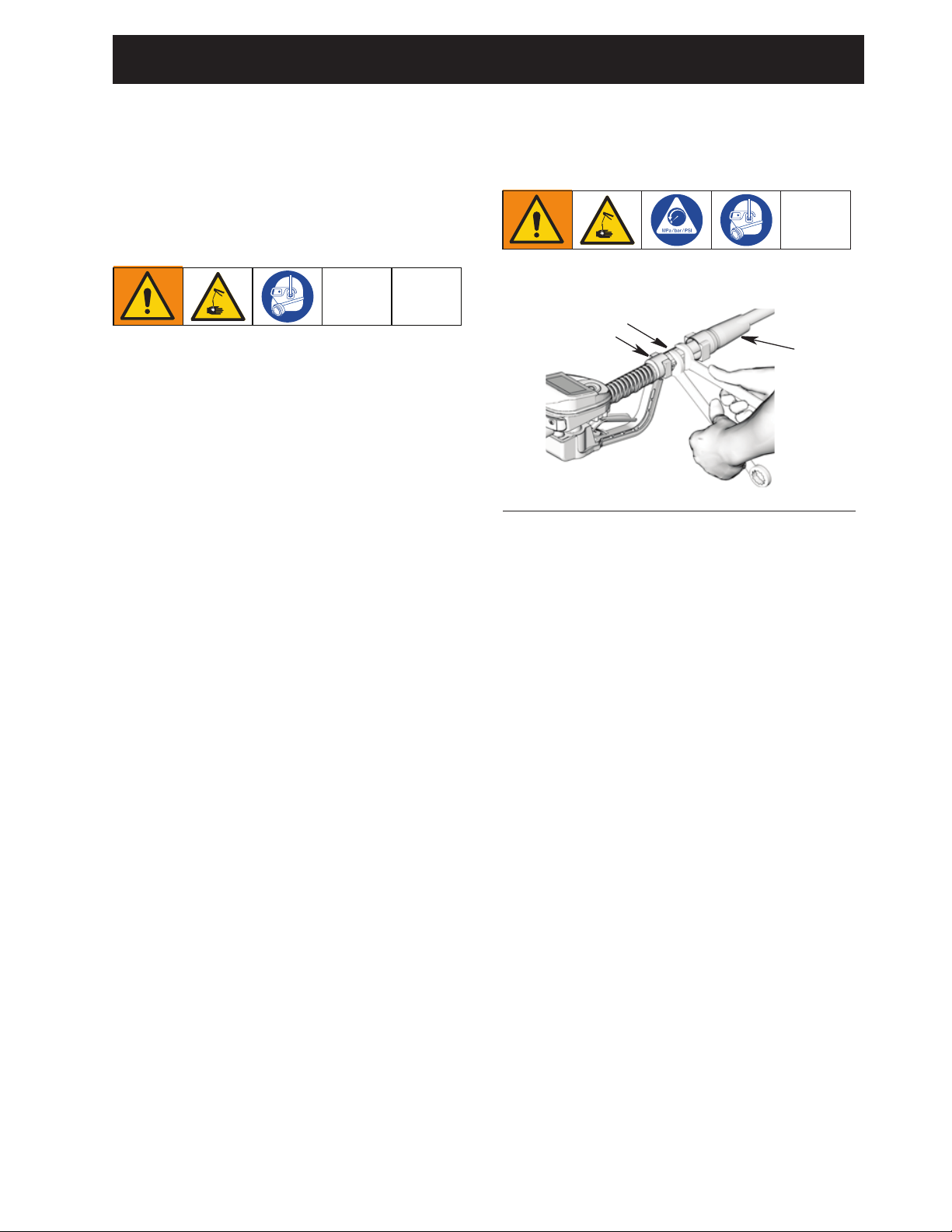
Install the Metered
Dispense Valve
1. Follow Pressure Relief Procedure,
page 10.
2. Slide the swivel boot (a) back, over the
hose, small end first to access the swivel
fitting (6) (FIG. 7).
3. Apply thread sealant to the male threads
of the hose fitting. Thread the hose fitting
(b) into the metered dispense valve
swivel (6). Use two wrenches to tighten
securely (FIG. 7).
NOTE: Allow the sealant to cure
according to the manufacturer’s
recommendations before circulating
fluid through the system.
4. Slowly open the fluid shut-off valve (B) at
the dispense position. Flush a sufficient
amount of oil to ensure that the entire
system is clean; then close the valve.
5. Repeat Step 4 at all other positions.
3A6673B 11
Page 12
Installation
12 3A6673B
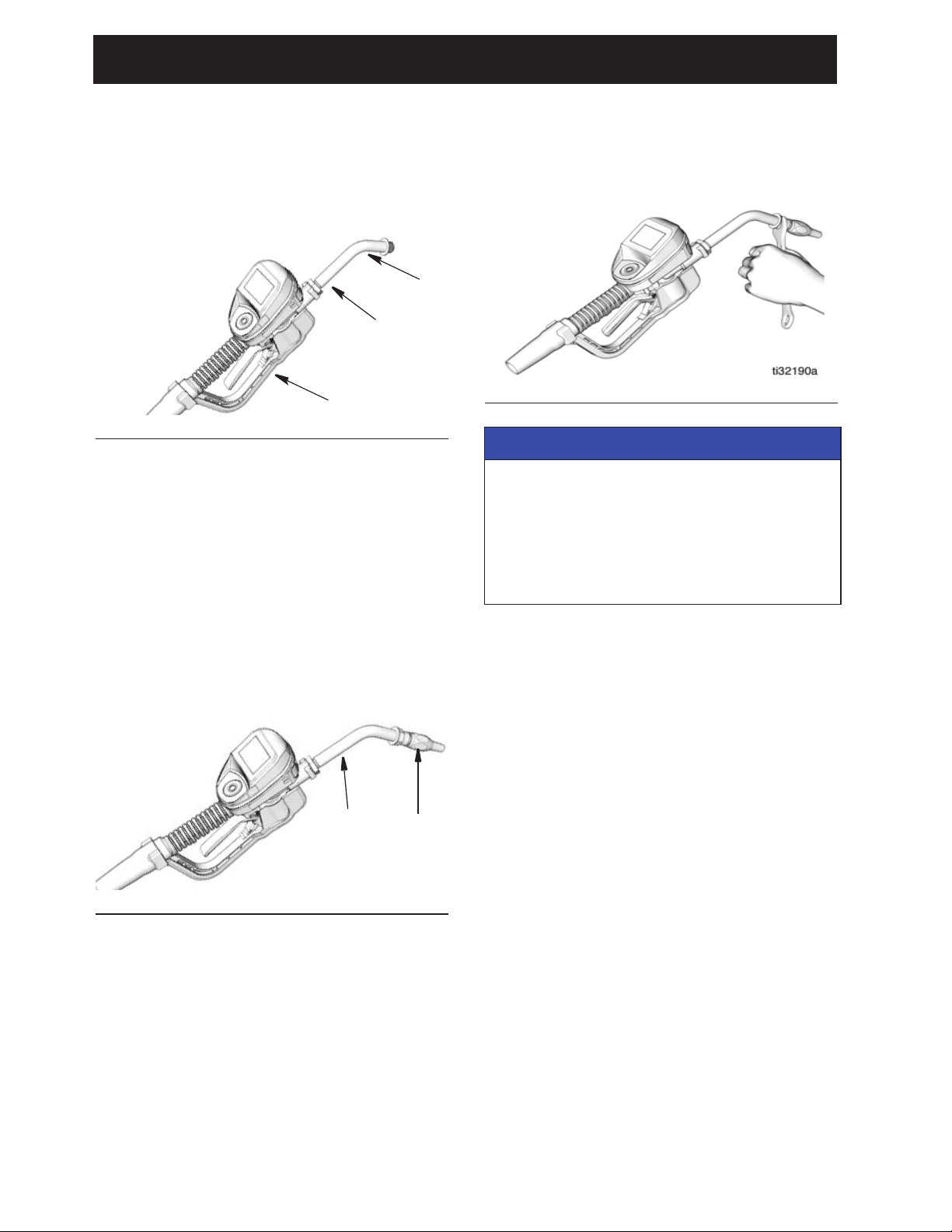
Install the Extension Tube
1. Adjust nut (c) on extension (2) so that the
maximum thread engagement of the
extension can be utilized (FIG. 8).
2. Thread extension (2) into housing until it
bottoms out (FIG. 8).
3. Align extension (2) with metered
dispense valve housing and handle (16)
(FIG. 8).
4. Firmly tighten nut (c) (F
IG. 8).
Install the Nozzle
1. Thread nozzle (3) onto extension (2)
(F
IG. 9).
2. With an open-end adjustable wrench on
the flats of the nozzle bushing, tighten
firmly (FIG. 10).
3. Open the automatic twist lock nozzle and
all fluid shut-off valves. Start pump to
pressurize system.
4. To ensure dispensing accuracy, purge all
air from the fluid lines and metered
dispense valve before use.
5. Set the system flow to the desired flow
rate. This is typically done by adjusting
the pump air pressure.
FIG. 8
FIG. 9
2
16
c
3
2
FIG. 10
NOTICE
• To prevent nozzle damage, only tighten
nozzle with wrench on flats of the
nozzle bushing as shown in FIG. 10.
• Do not disassemble the bushing
from the nozzle. Disassembly will
affect the performance of the nozzle.
Page 13
Preset Mode
3A6673B 13
Preset Mode
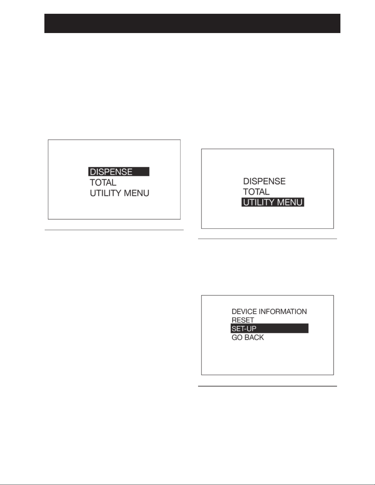
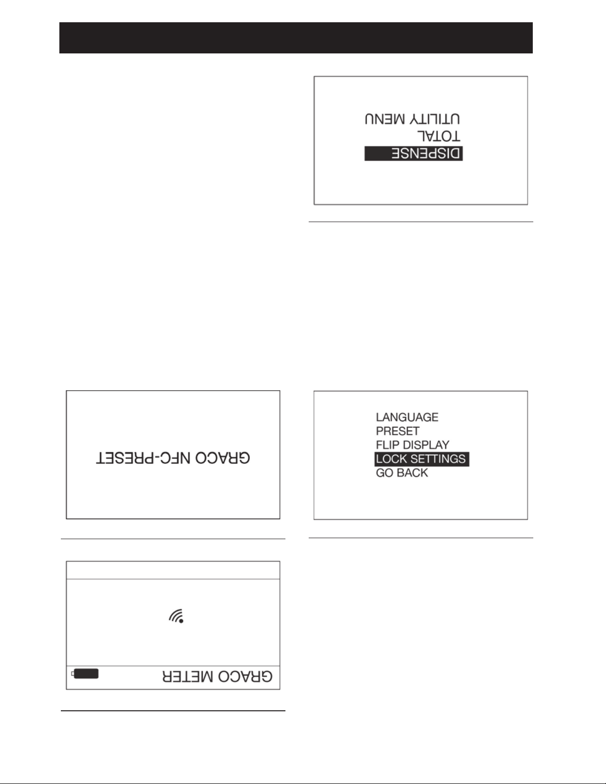
Main Menu Screen
This screen provides access to the main
metered dispense valve functions:
• DISPENSE, page 18
• TOTAL, page 21
• UTILITY MENU, page 21
Calibration
NOTE:
• This calibration procedure requires a
one quart or one liter clean, calibrated,
volumetric flask. When the meter is
configured to display fluid volume in
pints, quarts, or gallons, the calibration
procedure will require a one quart
calibrated, volumetric flask be used.
When the meter is configured in liters, a
one liter volumetric flask is required for
calibration.
• The metered dispense valve must be
flushed and primed prior to calibration
(see Flushing, page 11).
• The metered dispense valve should be
calibrated prior to using it for the first
time. Calibrating the metered dispense
valve assures that the dispenses are
accurate.
Calibration factors can vary due to fluid
viscosity and flow rate.
Calibrate the metered dispense valve for
specific fluids at nominal flow rates.
This calibration procedure requires a one
quart or one liter calibrated, volumetric flask.
If a one quart or one liter calibrated,
volumetric flask is not available, see Alternate
Calibration instructions, page 16.
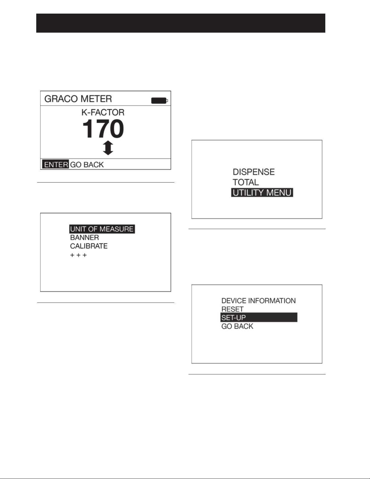
To calibrate the metered dispense valve:
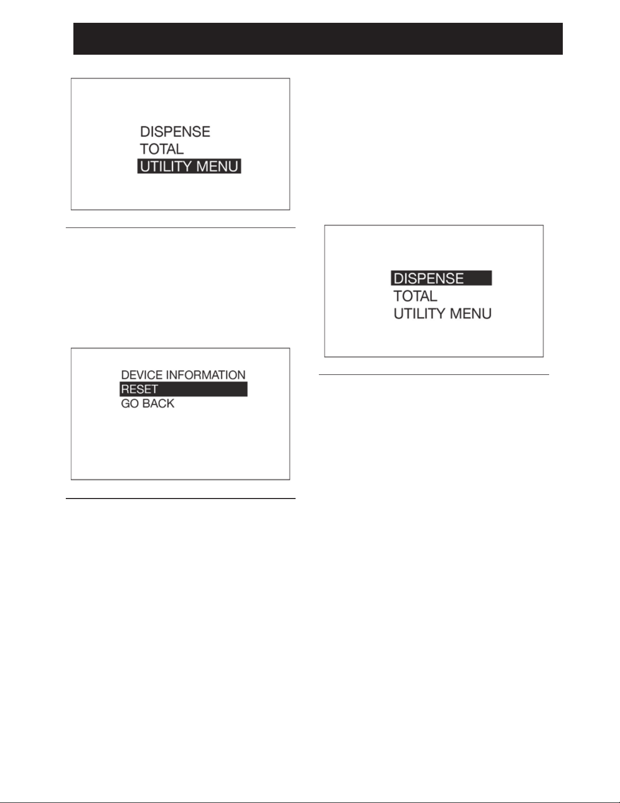
1. Use the UP or DOWN ARROW button on
the keypad to highlight UTILITY MENU
(FIG. 12) and then press the center
ENTER button on the keypad to select
the UTILITY MENU option.
2. Use the UP or DOWN ARROW button on
the keypad to highlight SET-UP (F
IG. 13)
and then press the center ENTER button
on the keypad to select the SET-UP
option.
FIG. 11
FIG. 12
FIG. 13
Page 14
Preset Mode
14 3A6673B
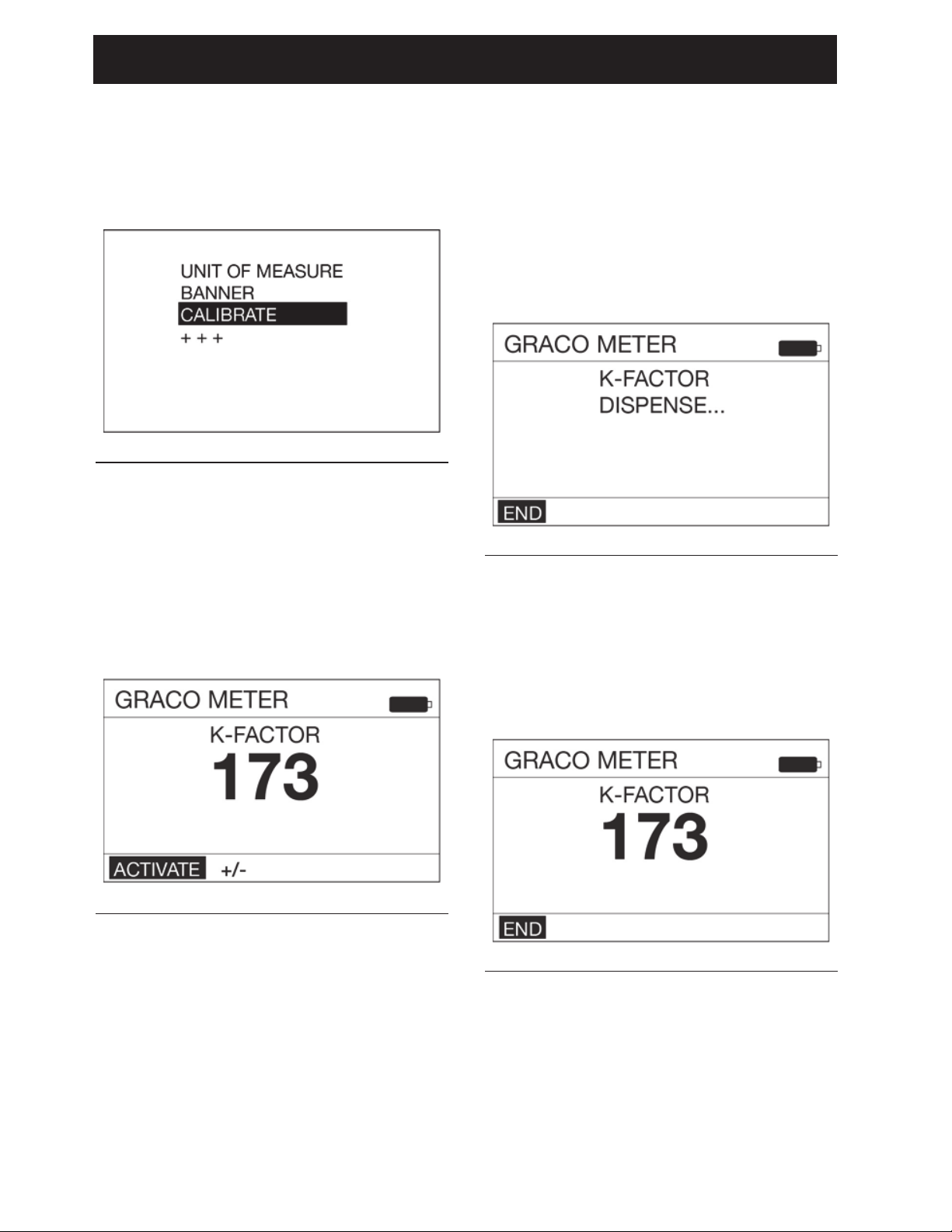
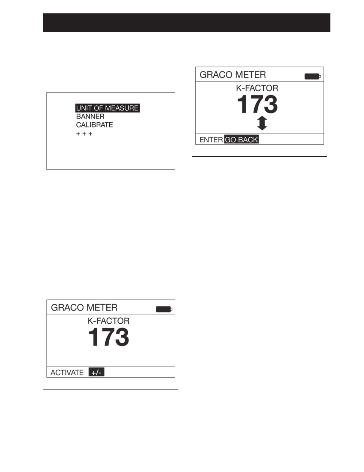
3. Use the UP or DOWN ARROW button on
the keypad to highlight CALIBRATE (FIG.
14) and then press the center ENTER
button on the keypad to select the
CALIBRATE option.
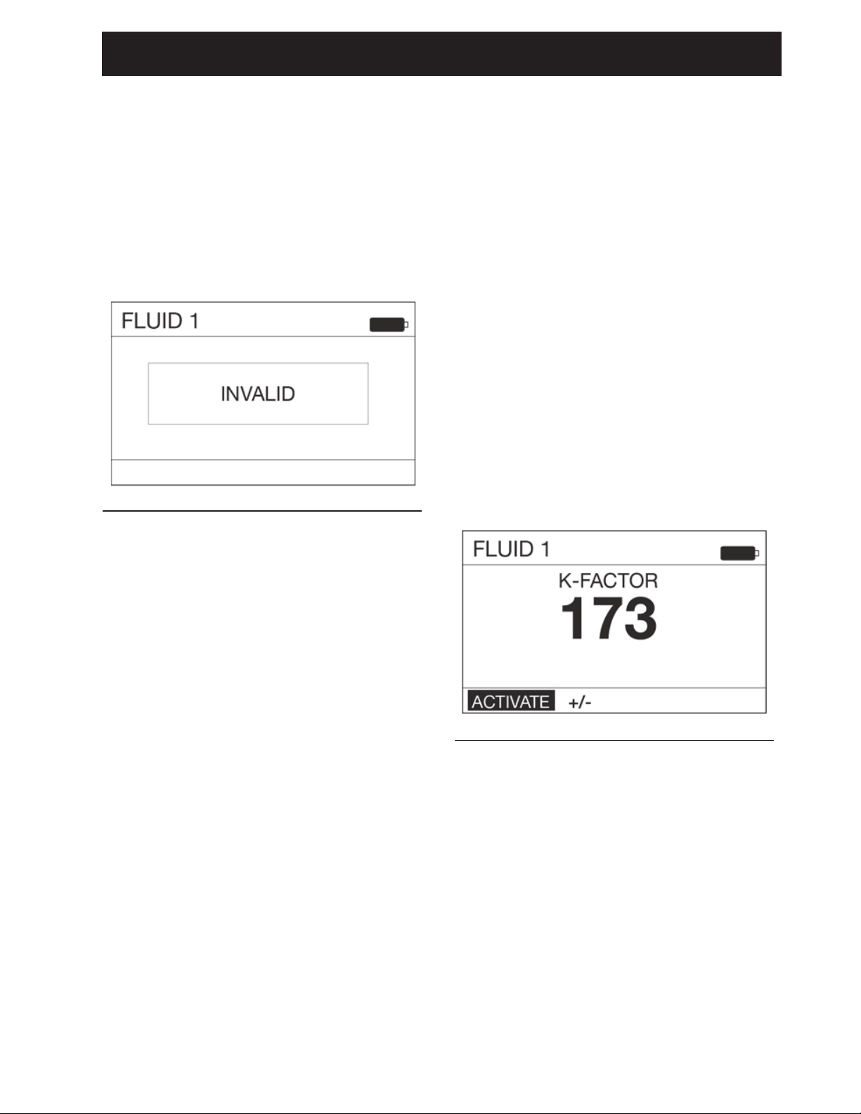
4. The calibration k-factor screen shown in
F
IG. 15 displays.
NOTE: The number shown on the
display is the k-factor the meter is
currently using. After completing the
calibration procedure this number may
be the same or different than what is
currently shown on the display.
5. Select ACTIVATE and press the center
ENTER button on the keypad to begin
metered dispense valve calibration (FIG.
15).
NOTE: The +/- on this screen is used for
Manual Calibration. See Manual
Calibration instructions on page 15.
6. Dispense exactly one quart or one liter of
fluid into the one quart or one liter clean,
calibrated, volumetric flask.
NOTE: During the dispense the metered
dispense valve will not display the
volume dispensed. The volume
dispensed is only determined by the
flask measurement. A screen displays
(F
IG. 16) during the calibration dispense.
7. When exactly one quart or one liter of
fluid is dispensed into the flask use the
center ENTER button on the keypad to
select END. A screen displaying the
quantity of fluid dispensed displays (FIG.
17 shows an example of the dispensed
volume screen).
FIG. 14
FIG. 15
FIG. 16
FIG. 17
Page 15
Preset Mode
3A6673B 15
8. Press the center ENTER button on the
keypad again to select END and save the
new calibration factor.
9. After selecting END the following screen
(F
IG. 18) displays.
Manual Calibration
NOTE: This Manual Calibration procedure is
used when the k-factor is known and a simple
adjustment of the displayed k-factor is
needed to set that number.
1. Follow steps 1- 4 of the Calibration
instructions, beginning on page 13.
2. Use the RIGHT ARROW button on the
keypad to highlight +/- and press the
center ENTER button on the keypad to
select the +/- option (F
IG. 19).
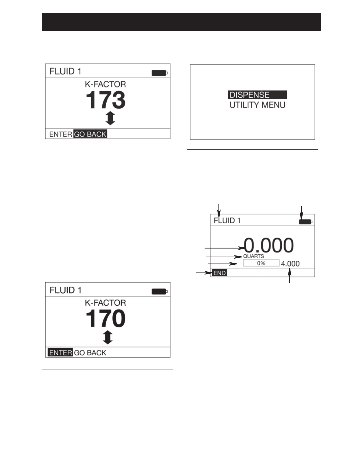
3. The k-factor adjustment screen shown in
FIG. 20 displays.
4. Use the UP and DOWN ARROW to
increase or decrease the displayed
k-factor until the new k-factor displays on
the screen.
NOTE: Selecting the GO BACK Function
on this screen returns the display to the
previous screen (shown in F
IG. 19).
FIG. 18
FIG. 19
FIG. 20
Page 16
Preset Mode
16 3A6673B
5. Be sure ENTER is highlighted in the
lower left corner of the display as shown
in F
IG. 21. Press the center ENTER
button on the keypad to save the new
calibration factor.
6. After selecting ENTER the following
screen (F
IG. 22) displays.
Alternate Calibration
NOTE: This alternate calibration procedure is
used when a one quart or one liter calibrated,
volumetric flask is not available.
1. Dispense a known volume of fluid into
any sized clean, calibrated, volumetric
flask. Note this volume as the VOLUME
DISPENSED (see Calculating k-factor,
Step 11, page 18).
2. Record the volume displayed on the
metered dispense valve. Note this
volume as the VOLUME DISPLAYED
ON THE METERED DISPENSE VALVE
(see Calculating the k-factor, Step 11,
page 18).
3. Use the UP or DOWN ARROW button on
the keypad to highlight UTILITY MENU
(F
IG. 23) and then press the center
ENTER button on the keypad to select
the UTILITY MENU option.
4. Use the UP or DOWN ARROW button on
the keypad to highlight SET-UP (F
IG. 24)
and then press the center ENTER button
on the keypad to select the SET-UP
option.
FIG. 21
FIG. 22
FIG. 23
FIG. 24
Page 17
Preset Mode
3A6673B 17
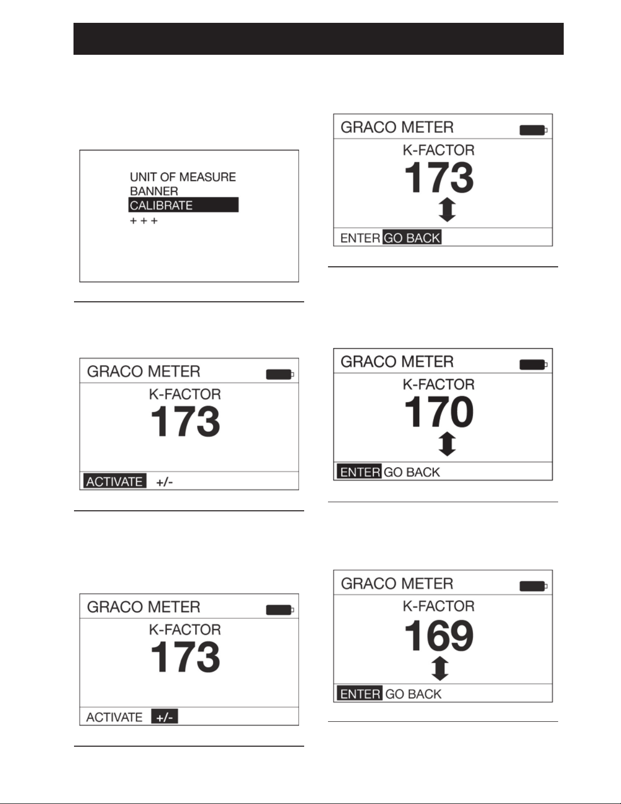
5. Use the UP or DOWN ARROW button on
the keypad to highlight CALIBRATE (FIG.
25) and then press the center ENTER
button on the keypad to select the
CALIBRATE option.
6. The calibration k-factor screen shown in
F
IG. 26 displays.
7. Use the RIGHT ARROW button on the
keypad to highlight +/- and press the
center ENTER button on the keypad to
select the +/- option (FIG. 27).
8. The k-factor adjustment screen shown in
FIG. 28 displays.
9. Use the UP and DOWN ARROW to
increase or decrease the displayed
k-factor (F
IG. 29) until the new k-factor
displays on the screen.
10. Note the current k-factor is displayed. In
the example shown in FIG. 30 the k-factor
is 169.
FIG. 25
FIG. 26
FIG. 27
FIG. 28
FIG. 29
FIG. 30
Page 18
Preset Mode
18 3A6673B
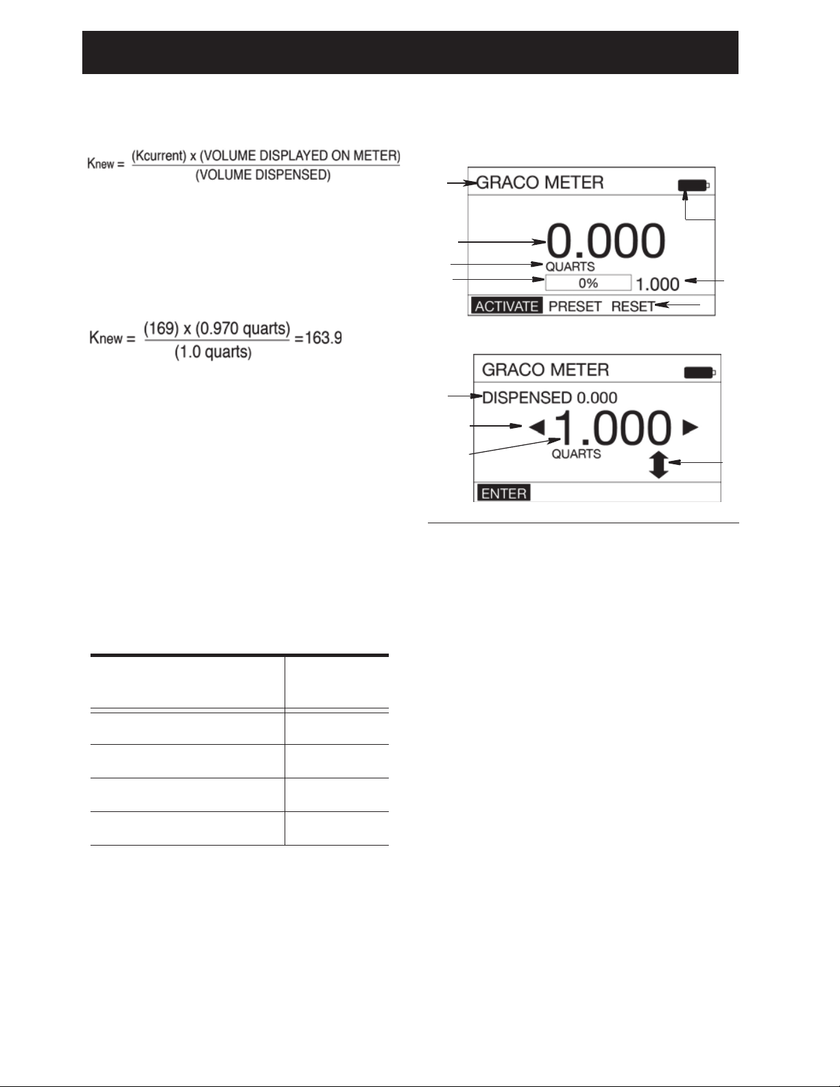
11. Calculate the new k-factor using the
following equation:
Example:
Kcurrent = 169
Volume displayed on metered dispense valve
= 0.970 quart
Volume dispensed = 1 quart
Round to the nearest whole number: 163.9 =
164.
NOTE: The unit of measurement for both
volumes must be the same in the above
equation.
12. Use the UP or DOWN ARROWS to
adjust the k-factor to the k-factor (Knew)
calculated in Step 11.
See Table 1, page 18 for recommended fluid
calibration factors.
NOTE: The calibration number may vary
slightly due to temperature or rate of flow.
Table 1
13. Press the center ENTER button on the
keypad to complete the calibration
operation and save the new calibration
factor.
DISPENSE
A BANNER - Unique identification name. See
Utility Menu/Set-Up/BANNER, page 23 for
instructions for creating the banner.
B BATTERY INDICATOR - When the batter-
ies are fully charged, the battery is completely filled in. As the battery discharges,
the amount of battery that is filled-in
declines.
C FUNCTION COMMAND - Function com-
mand options appear at the bottom of the
display when applicable to the task being
performed. Options when in the Dispense
mode include:
ACTIVATE - Activates the trigger to begin a
dispense.
PRESET - Preset dispense adjustment
screen displays.
RESET - Resets the dispense settings.
ENTER - Saves changes or updates.
NOTE: Additional function commands will
appear throughout the following instructions. when applicable
Fluid Calibration
Factor
Oil (10W30) 173
Gear Lube 173
ATF 173
Antifreeze 150
FIG. 31
C
D
E
F
H
G
J
H
K
L
PRESET ADJUSTMENT SCREEN
DISPENSE SCREEN
A
B
Page 19

Preset Mode
3A6673B 19
D DISPENSED FLUID COUNTER- As fluid is
dispensed, this number increases to reflect
the quantity of fluid that is being dispensed.
NOTE: If RESET was not selected after the
previous dispense was completed, the
amount of fluid dispensed in the previous
dispense will be shown in this field. If
RESET was selected, the field will show
0.000.
E UNIT OF MEASURE - Pints, Quarts, Gal-
lons or Liters. For instructions on setting the
Unit of Measure see UTILITY
MENU/SET-UP/UNIT OF MEASURE, page
23.
F PROGRESS BAR - Graphic representation
of the progression of the dispense shown by
gradually filling-in the empty space in the
bar. A textual representation of the progress
is also shown in a percentage format.
G PRESET AMOUNT - The volume of fluid
that the meter is currently set up to dispense
in PRESET Mode. See UTILITY
MENU/SET-UP/PRESET, page 25.
H ADJUSTABLE PRESET - Shows the vol-
ume of fluid that the meter is currently set up
to dispense in PRESET. Press the UP or
DOWN arrow on the keypad to increase or
decrease this quantity.
J DISPENSED - The amount of fluid previ-
ously dispensed.
K INCREASE/DECREASE ARROW - The
up/down arrow on the screen
indicates the
user can increase or decrease the PRESET
quantity before starting the dispense. Use
the UP or DOWN ARROW button on the key
pad to increase or decrease the PRESET
amount.
L PRESET SELECTION - The left and right
arrow on the screen indicate the user can
select a different PRESET option (1-5).
Press the LEFT or RIGHT ARROW button
on the key pad to scroll through the PRESET
options 1 - 5 (set up in UTILITY
MENU/SET-UP/PRESET, page 25).
Preset Dispense
1. Wake up the metered dispense valve by
pressing any button on the key pad (FIG.
1, page 7).
2. If ACTIVATE (A) is not highlighted, use
the LEFT or RIGHT ARROW button on
the keypad to highlight ACTIVATE (F
IG.
31); then press the center, ENTER
button on the keypad to select it.
The following screen (FIG. 32) displays
after ACTIVATE
is selected.
3. Squeeze the trigger to dispense fluid. A
numeric volume of dispensed fluid
displays
in field (D) and increases while
the fluid is dispensed.
The progress bar (F) fills-in and a
numeric percentage increases as the
amount of fluid dispensed nears the
Preset amount.
4. When the PRESET amount of fluid has
been dispensed the trigger deactivates,
stopping the fluid flow.
FIG. 32
D
F
Page 20

Preset Mode
20 3A6673B
5. The screen shown in FIG. 33 displays.
Notice the word “DONE” near the top of
the screen, confirming the requested
PRESET amount of fluid has been
dispensed. The progress bar (F) now is
entirely filled in and shows 100% of the
fluid requested has been dispensed and
the Dispensed Fluid Counter (D) now
shows 1.000 matching the chosen
PRESET parameters (K).
6. Use the LEFT ARROW on the keypad to
highlight RESET. Press the ENTER
button on the keypad to reset the meter
to 0.000 to prepare it for the next
dispense.
7. Use the RIGHT ARROW on the keypad
to highlight END. Press the center
ENTER button on the keypad to return to
the Main Menu Screen.
NOTE: If RESET was not selected after
the dispense was completed, the
amount of fluid dispensed in the last
dispense will be shown in this field. If
RESET was selected, the field will show
0.000.
STOP Function
During the dispense the word STOP (FIG. 32)
is highlighted on the lower left corner of the
dispense screen. To interrupt the dispense at
any time during the fill:
1. Release the trigger and press the center
ENTER button on the key pad.
Notice the word “STOPPED” appears
across the top of the display (F
IG. 34).
2. Use the LEFT or RIGHT ARROW button
on the keypad to highlight either:
• END - Ends the dispense and
returns the meter to the MAIN
MENU screen.
• PRESET - Allows for increasing,
decreasing or entirely changing the
amount of fluid for the PRESET
selection. The screen shown in FIG.
31 displays. See Function
Command (C)/PRESET, page 18
for instructions on changing the
PRESET).
• RESET
- Resets the Dispensed
Fluid Counter (D) back to 0.000.
3. After making changes use the LEFT
ARROW button on the keypad to
highlight END. Press the center ENTER
button on the key pad to select END and
return to the Dispense screen to
complete the dispense.
FIG. 33
D
F
K
FIG. 34
Page 21

Preset Mode
3A6673B 21
TOTAL
M LIFETIME TOTAL - Running, non-resettable
total quantity fluid that has been dispensed
over the life of the meter. The unit of measurement displayed is determined by the
Unit of Measurement criteria selected in
UTILITY MENU/SET-UP/UNIT OF MEASURE, page 23. When Pints, Quarts or Gallons is selected the Unit of Measurement will
be shown as Gallons. When Liter is selected
the Unit of Measurement will be shown as
Liters.
N RESETTABLE TOTAL - Running total of the
quantity of fluid dispensed through the meter
since the previous total was reset. The unit
of measurement displayed is determined by
the Unit of Measurement criteria selected in
UTILITY MENU/SET-UP/UNIT OF MEASURE, page 23.
GO BACK - Returns to Main Menu screen.
RESET - Resets the Resettable total.
UTILITY MENU
There are four Utility options available from
the UTILITY MENU screen.
• DEVICE INFORMATION, page 21
• RESET, page 22
• SET-UP SCREENS, page 22
• GO BACK, page 27
To select a UTILITY MENU:
1. Use the UP or DOWN ARROW button to
select the desired screen from the list.
2. When the screen is highlighted (FIG. 36),
press the ENTER button on the key pad.
DEVICE INFORMATION
The Device Information Screen is used for
diagnostics only. An example of this screen is
shown in FIG. 37.
FIG. 35
N
M
FIG. 36
FIG. 37
Unique device identification number
Meter firmware version 1_01_007
Page 22

Preset Mode
FIG. 41
RESET
Restarts meter. After selecting RESET the
screen display goes blank. After
approximately 10 seconds the screens
shown in F
NOTE: The screen shown in F
the user to upgrade for use with a Pulse FC
system. See Pulse FC Mode, page 28 for
instructions.
FIG. 38
IG. 38- FIG. 40 display.
IG. 38 allows
SET-UP SCREENS
The SET-UP Menu includes the following
options: UNIT OF MEASURE, BANNER,
CALIBRATE and “+++”.
A second SET-UP screen is accessed by
selecting the “+++”.
This screen includes options for
LANGUAGE, PRESET, FLIP DISPLAY and
LOCK SETTINGS. This screen also includes
a GO BACKoption to return to the user to the
UTILITY MENU screen.
FIG. 39
1. Use the UP or DOWN ARROW button on
the keypad to select one of the SET-UP
options.
2. When the desired SET-UP option is
highlighted, press the center ENTER
button on the keypad
FIG. 40
When the MAIN MENU Screen shown in F
40 displays, the meter is ready to use.
22 3A6673B
IG.
Page 23

Preset Mode
3A6673B 23
UNIT OF MEASURE
The meter is factory-set to quarts. The UNIT
OF MEASURE screen configures the meter
to dispense in PINTS, QUARTS, GALLONS
OR LITERS. This screen also includes a GO
BACK option to return to the Utility Menu
screen.
1. Use the UP or DOWN ARROW button on
the keypad to select the desired unit of
measure from the displayed list: PINTS,
QUARTS, GALLONS, LITERS or GO
BACK.
2. When the desired unit of measure is
highlighted, press the center ENTER
button on the keypad.
BANNER
The banner screen is used to assign a name
to the meter, such as Meter 1, Meter 2, etc.
This is useful in shops that have more than
one meter in their system.
Names can be made up of any combination of
letters or numbers.
The maximum number of characters is 15.
1. Use the UP, DOWN, LEFT and RIGHT
ARROW buttons on the keypad to select
letters and numbers needed to name the
meter.
2. Press the center ENTER button on the
keypad after each desired letter or
number is highlighted to select it.
3. When you have finished naming the
meter, use the RIGHT ARROW button
on the keypad to highlight the symbol.
Press the center ENTER button on the
keypad to return to the SET-UP Menu
Screen.
NOTE: The BANNER created displays
on the top left corner of the screen.
FIG. 42
FIG. 43
Page 24

Preset Mode
24 3A6673B
CALIBRATE
Calibrating the metered dispense valve
assures that dispenses are accurate. See
Calibration instructions beginning on page
13.
“+++”
Indicates there are additional functions;
LANGUAGE, FLIP DISPLAY, LOCK
SETTINGS and GO BACK are available on
the next screen.
LANGUAGE
The meter is factory-set to English. On the
first language screen it can be configured to
display in ENGLISH, FRENCH, GERMAN,
ITALIAN, “+++”.
A second language screen is accessed by
selecting the “
+++”.
This screen includes language options of
POLISH, PORTUGUESE, RUSSIAN AND
SPANISH. This screen also includes a GO
BACK option to return to the SET- UP Menu
screen.
1. Use the UP or DOWN ARROW button on
the keypad to select the desired
language from the displayed list:
ENGLISH, FRENCH, GERMAN,
ITALIAN, “
+++”.
POLISH, PORTUGUESE, RUSSIAN,
SPANISH or GO BACK
2. When the desired language is
highlighted, press the center ENTER
button.
FIG. 44
Page 25

Preset Mode
3A6673B 25
PRESET
The metered dispense valve can be
programmed to dispense 5 different preset
amounts.
1. Use the UP or DOWN ARROW button on
the keypad to highlight the desired
PRESET. Press the center ENTER
button to select it.
2. The screen shown in F
IG. 46 displays.
PRESET SETUP SCREEN
H PRESET AMOUNT DISPENSE VOLUME -
Shows the volume of fluid that the meter is
currently set up to dispense. Press the UP
and/or DOWN arrow on the keypad to
increase and/or decrease this quantity. On
the DISPENSE screen this amount is shown
in field (G) (See F
IG. 31, page 18).
K INCREASE/DECREASE ARROW - The
up/down arrow on the screen indicates the
user can increase or decrease the PRESET
quantity before starting the dispense. Use
the UP or DOWN ARROW button on the key
pad to increase or decrease the PRESET
amount.
P PRESET TITLE - Identifies which preset
option is being set up. The example in F
IG.
46 shows PRESET1. This means you are
setting up the PRESET parameters for PRESET1 in the list.
R NAME - Additional information about the
PRESET, such as the type of engine or vehicle make/model, fluid type, etc. The example
shown in F
IG. 46 shows F350 in the NAME
field on the display for PRESET1.
Creating a PRESET
Be sure ENTER in the lower left corner of the
display screen is highlighted (F
IG. 46).
1. Use the UP AND DOWN ARROW on the
keypad to increase or decrease the
PRESET AMOUNT (H) (FIG. 46).
2. When you have finished setting the
amount, press the center ENTER button
on the keypad to save the PRESET.
To SET-UP a PRESET NAME:
1. Use the RIGHT ARROW on the keypad
to highlight NAME (F
IG. 46). Press the
center ENTER button on the keypad to
select NAME.
2. The screen shown in FIG. 47 displays.
This screen can be used to create a
unique description for the PRESET.
3. Use the UP, DOWN, LEFT and RIGHT
ARROW buttons on the keypad to select
the letters and numbers needed to name
the PRESET.
FIG. 45
FIG. 46
H
K
P
R
FIG. 47
Page 26
Preset Mode
26 3A6673B
4. Press the center ENTER button on the
keypad after each letter or number is
highlighted to select it.
5. After naming the PRESET, use the
RIGHT ARROW button on the keypad to
highlight the symbol. Press the center
ENTER button on the keypad to return to
the PRESET Setup Screen.
6. ENTER in the lower left corner of the
display should be highlighted. If there
are no additional changes, press the
center ENTER button on the keypad to
save the PRESET and return to
PRESET Menu Screen.
FLIP DISPLAY
Allows for viewing data on the metered
dispense valve display upside down for oil bar
installation. After selecting FLIP DISPLAY,
the meter display goes blank for about 10
seconds. After approximately 10 seconds the
screens shown in FIG. 48 - FIG. 50 display.
When the MAIN MENU Screen shown in FIG.
50 displays, the meter is ready to use.
LOCK SETTINGS
Prevents unauthorized access to meter
settings.
To lock the meter:
1. Use the DOWN ARROW button to select
LOCK SETTINGS in the list.
To unlock the meter:
1. Use the DOWN ARROW button on the
keypad to highlight UTILITY MENU.
2. Press the center ENTER button on the
keypad to select it.
FIG. 48
FIG. 49
FIG. 50
FIG. 51
Page 27
Preset Mode
3A6673B 27
3. The menu shown in FIG. 53 displays. Use
the DOWN ARROW button to highlight
RESET in the list.
NOTE: Do not press the center ENTER
button after RESET is selected.
Continue to step 4.
4. Press and hold the LEFT ARROW
button.
5. While still holding down the LEFT
ARROW button, press the CENTER
button.
DEVICE INFORMATION
See page 21 for a description of this screen.
RESET
See page 22 for a description of this screen.
GO BACK
Returns to the Main Menu Screen (FIG. 54).
FIG. 52
FIG. 53
FIG. 54
Page 28

Pulse FC Mode
28 3A6673B
Pulse FC Mode
Pulse FC Mode is only available with the
purchase and installation of a Pulse FC
Starter Kit (P/N 26C401). The kit contains
everything needed to begin using Pulse FC
with the meter, including a programmer and a
software license.
Pulse FC uses NFC tags that are
programmed to initiate different functions on
the meter.
• Profile tags and fluid totalizer tags can
program meter profiles and receive
actual dispensed totalizer values from
multiple meters.
• Fluid dispense vouchers and calibration
vouchers can be used with only a single
meter before they must be
reprogrammed.
Tags may be purchased from Graco as packs
of cards. When a tag or voucher is referenced
in this manual, it refers to a card programmed
to perform the designated function.
Enable Pulse FC Mode
1. Press the center ENTER button on the
keypad to activate the meter, waking it
from sleep mode. The screen shown in
F
IG. 55 displays.
NOTE: The screen in FIG. 55 only
appears in Preset Mode the first time the
meter is powered on. After the first power
on, a meter in Preset Mode must be
RESET to get to this screen. See RESET
instructions, page 22.
2. Hold the profile tag to the display. When
the profile tag is valid, a CONFIGURING
(FIG. 56) message appears on the
display.
NOTE: After the meter is placed in Pulse
FC mode, it will only accept vouchers
and tags configured by the same system
used to make the profile tag.
3. After the meter has been successfully
configured, the main menu screen
shown in FIG. 57 displays.
FIG. 55
FIG. 56
FIG. 57
Page 29
Pulse FC Mode
3A6673B 29
Activation
1. Press the center ENTER button on the
keypad to activate the meter. The screen
shown in FIG. 55 displays.
2. Hold the voucher or tag to the display. If
the meter does not recognize the
voucher or tag, an INVALID (FIG. 58)
message displays
Calibration
NOTE:
• This calibration procedure requires a
one quart or one liter clean, calibrated,
volumetric flask. When the meter is
configured to display fluid volume in
pints, quarts, or gallons, the calibration
procedure will require a one quart
calibrated, volumetric flask be used.
When the meter is configured in liters, a
one liter volumetric flask is required for
calibration.
• The metered dispense valve must be
flushed and primed prior to calibration
(see Flushing, page 11).
• A calibration voucher specifically
configured for calibration is required.
• The metered dispense valve should be
calibrated prior to using it for the first
time. Calibrating the metered dispense
valve assures that dispenses are
accurate.
Calibration factors can vary due to fluid
viscosity and flow rate.
Calibrate the metered dispense valve for
specific fluids at nominal flow rates.
This calibration procedure requires a one
quart or one liter calibrated, volumetric flask.
If a one quart or one liter calibrated,
volumetric flask is not available, see
Alternate Calibration instructions, page 16.
To calibrate the metered dispense valve:
1. Activate the meter. See Activation,
page 29.
2. If the meter recognizes the calibration
voucher, the configuration screen shown
in FIG. 59 displays.
3. The calibration k-factor screen shown in
FIG. 59 displays. The number shown on
the display is the k-factor the meter is
currently using. After completing the
calibration procedure this number may
be the same or may be different than
what is currently shown on the display.
4. Highlight ACTIVATE and press the
center ENTER button on the keypad
(FIG. 15).
NOTE: The +/- on this screen is used for
Manual Calibration. See Manual
Calibration instructions on page 30.
FIG. 58
FIG. 59
Page 30

Pulse FC Mode
30 3A6673B
5. Dispense exactly one quart or one liter
of fluid into a one quart or one liter clean,
calibrated, volumetric flask.
NOTE: During calibration dispense the
metered dispense valve will not display
the volume dispensed. The volume
dispensed is only determined by the
flask measurement. The following
screen displays during the calibration
dispense.
6. When exactly one quart or one liter of
fluid is dispensed into the flask use the
center ENTER button on the keypad to
select END. A screen displaying the
quantity of fluid dispensed displays (FIG.
61 shows an example of the dispensed
volume screen).
7. Press the center ENTER button on the
keypad to save the new calibration
factor.
8. After selecting END the Main Menu
screen displays.
Manual Calibration
NOTE: This Manual Calibration procedure is
used when the k-factor is known and a simple
adjustment of the displayed k-factor is
needed.
1. Follow steps 1- 3 of the Calibration
instructions (page 29).
2. Use the RIGHT ARROW button on the
keypad to highlight +/- and press the
center ENTER button on the keypad to
select the +/- option (F
IG. 63).
FIG. 60
FIG. 61
FIG. 62
FIG. 63
Page 31
Pulse FC Mode
3A6673B 31
3. The k-factor adjustment screen shown in
FIG. 64 displays.
4. Use the UP and DOWN ARROW to
increase or decrease the displayed
k-factor until the new k-factor displays on
the screen.
NOTE: Selecting the GO BACK Function
on this screen returns the display to the
previous screen (shown in F
IG. 63).
5. After adjustments to the k-factor are
complete, ENTER should be highlighted
in the lower left corner of the display as
shown in F
IG. 65. Press the center
ENTER button on the keypad to select
ENTER and save the new calibration
factor.
After selecting ENTER the Main Menu screen
shown in F
IG. 66 displays.
DISPENSE
Screen Identification
A BANNER - Name of the fluid assigned to the
meter in Pulse FC. This can only be set up
by a Pulse FC profile tag.
B BATTERY INDICATOR - When the batter-
ies are fully charged, the battery is completely filled in. As the battery discharges,
the amount of battery that is filled-in
declines.
C FUNCTION COMMAND - Function com-
mand options appear at the bottom of the
display when applicable to the task being
performed. END is the only Dispense screen
option.
FIG. 64
FIG. 65
FIG. 66
FIG. 67
A
B
C
D
E
F
G
Page 32

Pulse FC Mode
32 3A6673B
D DISPENSED FLUID COUNTER- As fluid is
dispensed, this number increases to reflect
the quantity of fluid that is being dispensed.
E UNIT OF MEASURE - Pints, Quarts, Gal-
lons or Liters. Can only be set up by a Pulse
FC profile tag.
F PROGRESS BAR - Graphic representation
of the progression of the dispense shown by
gradually filling-in the empty space in the
bar. A textual representation of the progress
is also shown in a percentage format.
G PRESET AMOUNT - The volume of fluid
that the meter is currently authorized to dispense. The value set by a Pulse FC fluid
voucher.
To dispense fluid:
1. Activate the meter. See Activation,
page 29.
2. If the meter recognizes the fluid voucher,
the DISPENSE screen shown in F
IG. 68
displays.
NOTE: All dispense parameters are
already set up including the unit of
measurement and the total amount of
fluid that can be dispensed. Adjustments
cannot be made to these parameters.
3. Squeeze the trigger to begin dispensing
fluid. A numeric volume of dispensed
fluid displays in field (D) and increases
while the fluid is dispensed.
The progress bar
(F) fills-in and a
numeric percentage increases as the
amount of fluid dispensed nears the
Preset amount.
4. When the PRESET amount of fluid has
been dispensed the trigger deactivates,
stopping the fluid flow.
5. END is highlighted. Press the center
ENTER button on the key pad to end the
dispense. The Main Menu screen
displays.
END Function
During the dispense the word END (FIG. 68)
is highlighted on the lower left corner of the
dispense screen. To interrupt the fill during
dispensing:
1. Release the trigger and press the center
ENTER button on the key pad to select
END.
2. The dispense ends and immediately
returns the meter to the MAIN MENU
screen. The dispense is complete.
NOTE: In Pulse FC Mode you continue
dispensing fluid to finish an interrupted
dispense.
FIG. 68
D
F
Page 33

Pulse FC Mode
FIG. 71
Unique device identification number
Meter firmware version 1_01_007
UTILITY MENU
There are three Utility options available from
the UTILITY MENU screen.
• DEVICE INFORMATION, page 33
• FLIP DISPLAY, page 34
• GO BACK, page 34
To select a UTILITY MENU:
1. Activate the meter. No voucher or tag is
required to access the menu. See
Activation, page 29.
2. Press the center ENTER button on the
keypad a second time to bypass the
screen in FIG. 55. The Main Menu screen
shown in FIG. 69 displays.
6. Use the UP or DOWN ARROW button to
select the desired screen from the list.
7. When the screen is highlighted, press
the ENTER button on the key pad.
DEVICE INFORMATION
The Device Information Screen is used for
diagnostics only. An example of this screen is
shown in FIG. 71.
FIG. 69
3. If UTILITY MENU is not highlighted, use
the DOWN ARROW on the key pad to
highlight it.
4. Press the center ENTER button on the
key pad to select UTILITY MENU.
5. The UTILITY MENU screen shown in
FIG. 70 displays.
FIG. 70
3A6673B 33
Page 34

Pulse FC Mode
FIG. 74
FLIP DISPLAY
Allows the data to be viewed on the metered
dispense valve display upside down for oil bar
installation. After selecting FLIP DISPLAY,
the meter display goes blank for about 10
seconds. After approximately 10 seconds the
screens shown in FIG. 72 - FIG. 73 display.
FIG. 72
GO BACK
Returns to the Main Menu Screen (FIG. 74).
FIG. 73
When the MAIN MENU Screen shown in FIG.
73 displays, the meter is ready to use.
34 3A6673B
Page 35

Service
3A6673B 35
Service
Battery Replacement
• Replace batteries with four AA, alkaline
batteries.
• Be sure to follow the correct polarity as
shown on the installation labels located
on either side of the metered dispense
valve when installing batteries in the
battery compartment (FIG. 76).
• Do not mix different types of batteries
together or old batteries with fresh
ones. Always replace all 4 batteries with
4, fresh, new AA batteries.
To change the battery:
1. Remove screws (36) from the battery
compartment cover (5).
2. Use a small, flat screwdriver to gently pry
the cover away from the metered
dispense valve housing on the bottom
side of the cover, near the extension
attachment as shown in FIG. 75.
3. Remove and separately recycle
batteries according to all applicable
regulations. Do not dispose of with
household or commercial waste.
4. Install 4 new batteries. See labels on the
each side of the housing and F
IG. 76 for
battery orientation.
5. Replace cover (5) and screws (36).
Tighten screws securely (FIG. 77).
NOTE: Do not over-tighten the screws.
FIG. 75
36
5
FIG. 76
FIG. 77
36
5
Page 36

Parts
19
37
29
28
27
5
36
2
3
14
17
21
20
15
18
6
16
10 4
13
12
Parts
FIG. 78
36 3A6673B
Page 37

Parts
Parts
Ref Part Description
VALVE, metered
1 ----
2 ---- EXTENSION
16Y863
255194 Rigid 1
255854
273079
3 ---- NOZZLE
17R220
17T207
255461 High Flow
255470 Gear Lube/ATF
4+ STRAINER, mesh 1
5 † 25M593 COVER, battery 1
6 SWIVEL, straight
247344
247345 3/4 in. NPT
24H097 1/2 - 14 BSPT
24H098 1/2- 14 BSPP
24H099 3/4 - 14 BSPT
24H100 3/4 - 14 BSPP
10+ 155332 PACKING, o-ring 1
12 ----
13 131258 PACKING, square ring 1
14 25D904
15 25M601 1
16 129830 COVER, trigger guard 1
17 16E337 SCREW, cap, sch, sst 2
18 131256
19 26C403 KIT, BEZEL, electrical 1
20 131257 PACKING, o-ring 4
21 25N342
27X ---- ROD, trip 1
28X 129623 SEAL, molded 1
29X ---- BALL, 5 mm 3
33 121413
36 † 112380 SCREW, mach, pan hd2
37 26C276 SOLENOID 1
dispense valve (see
models page X)
Flex
Gear Lube
Windshield washer
solvent
Automatic, quick close 1
Manual Antifreeze
1/2 in. NPT 1
HOUSING, metered
dispense valve
VALVE, metered
dispense valve, assy
SCREW, mach, torx
pan hd
SCREW, mach, torx
pan hd
BATTERY, pkg, 4 ct,
alkaline AA (not shown)
Qty
1
1
1
1
4
1
Related Kits
Ref Part Description
X 25D903
+ 25D906
† 25D907
KIT, Trip Rod Repair, includes
27, 28, 29
KIT, Swivel Filter, includes 4
and 10
KIT, Battery Cover, includes 5
and 36
3A6673B 37
Page 38

Troubleshooting
Problem Cause Solution
Battery dead icon is present. Batteries are low. Replace batteries, page 35.
Display does not activate Batteries are dead. Replace batteries, page 35.
Electronic control is
malfunctioning.
Replace the electronic bezel
assembly. Contact your
Graco distributor for
assistance ordering this
part.
Slow or no fluid flow Filter is clogged. Relieve pressure, page 10.
Clean or replace filter.
If the problem remains,
contact your Graco
distributor for repair or
replacement.
Pump pressure is low. Increase pump pressure.
Twist lock nozzle not fully
open.
Aim nozzle into bucket or
rag. Fully open nozzle.
Do not trigger metered
dispense valve when
nozzle is closed. If you do
accidentally trigger the
metered dispense valve with
the nozzle closed, point
nozzle into a waste bucket
and open the nozzle to
relieve pressure and expel
built up fluid.
Shut-off valve is not fully
open.
Fully open shut-off valve.
Foreign material is jammed
in the metered dispense
valve housing.
Contact your Graco
distributor for repair or
replacement.
Displayed dispensed
amount is not accurate
Unit needs to be calibrated
for the fluid that is being
dispensed.
Calibrate the metered
dispense valve for the fluid
that is being dispensed.
Troubleshooting
1. Perform pressure relief procedure,
page 10, before you check or repair the
metered dispense valve.
2. Verify that the pump, other valves, and
controls are operating properly.
38 3A6673B
Page 39

Troubleshooting
Problem Cause Solution
Metered dispense valve
leaks from cover/control
Metered dispense valve
leaks from twist lock nozzle.
It is important to distinguish
between the two causes of
this problem. A new nozzle
will NOT correct a fluid leak
caused by a faulty valve.
Metered dispense valve
leaks from swivel
Poor seal at metering cover
chamber
Twist lock nozzle has a
damaged seal.
Valve has damaged or
obstructed seals.
Poor swivel/hose
connection.
Poor swivel/metered
dispense valve housing
connection.
Swivel seals have
deteriorated and leak.
Contact your Graco
distributor for repair or
replacement.
Replace nozzle. See Install
the Nozzle, page 12.
Replace valve cartridge.
Replacement Kit part
25D904.
Apply PTFE tape (leave a
minimum of two engaged
threads uncovered for
electrical continuity) or
sealant to threads of hose
and tighten the connection.
Torque the fitting to 20-25
ft.-lb (27.12 - 34 N•m).
Replace swivel. Use Swivel
Seal and Filter Replacement
Kit 25D906. See Pulse
Metered Dispense Valve
Repair manual.
Unit does not stop
dispensing when assumed
preset amount is dispensed.
Screen locks up or freezes Firmware Issue Remove batteries. Wait five
Valve is dirty or seals are
defective.
Low battery. Replace batteries, page 35.
Solenoid not functioning Replace solenoid.
Replace valve cartridge.
Replacement Kit part
25D904.
minutes, then replace
batteries and restart.
3A6673B 39
Page 40

Error Codes
Error Codes
Error codes are listed below. Even in an error condition the unit keeps track of the amount
dispensed. Whenever an error code is displayed, you must end the dispense.
Error Code Cause Solution
Ensure that your flow rate is not higher
than 18 gpm (68 lpm). For further
assistance, contact your Graco
distributor.
End dispense
size.
Error 2
Reed Switch Error: Error occurred with
pick-up in internal gear.
Reed switch malfunction. Replace electronic bezel housing.
Unit was dropped or unit encountered
excessive vibration during shipping.
Air in fluid line. Fix leaks in pump suction line.
Excessive pulsation. Re-plump sump suction line to a larger
Error 4
Flow has continued after it should
have shut off.
Flow has occurred in lockout condition.
End dispense
40 3A6673B
Page 41

Technical Specifications
Technical Specifications
Metered Dispense Valve
US Metric
Flow range* 0.25 to 18 gpm 0.9 to 68 lpm
*Tested in 10W motor oil. Flow rates vary with fluid pressure, temperature and viscosity.
Maximum Working Pressure 1500 psi 10.34 MPa, 103.4 bar
Units of Measure (factory set to
quarts)
Weight 5.3 pounds 2.4 kg
Dimensions (without extension)
Length 13 inches 33 cm
Width 3.75 inches 9.5 cm
Height 5.75 inches 14.6 cm
Units of measure (factory set in
quarts)
Inlet 1/2-14 npt or 3/4-14 npt
Outlet 3/4-16 straight thread o-ring boss
Operating temperature range 4°F to 158°F -16°C to 70°C
Storage temperature range -40°F to 158°F -40°C to 70°C
Battery** 4AA alkaline batteries
**Recommended Battery: Energizer
NFC Frequency Band 13.56 Mhz
Maximum NFC Transmit Power 1 mW (0 dBm)
Wetted parts aluminum, stainless steel, PBT, nitrile rubber, zinc plated
Fluid compatibility antifreeze, gear oil, crankcase oil, ATF
Metered Dispense Valve
Accuracy†
† At 2.5 gpm (9.5 lpm), at 70°F (21°C), with 10-weight oil and one gallon dispensed. May
require calibration.
pints, quarts, gallons liters
maximum recorded dispensed volume = 9999 units
maximum preset volume = 9999 units
®
Alkaline E91.
carbon steel, nickel plated carbon steel
+/- 0.5 percent
3A6673B 41
Page 42

Technical Specifications
FCC / IC Notice
Contains FCC ID: JHI-SDPMETER
Contains IC: 4840A-SDPMETER
The enclosed device complies with Part 15 of the FCC Rules and with Industry Canada
license-exempt RSS standard(s). Operation is subject to the following two conditions:(1) this
device may not cause harmful interference and (2) this device must accept any interference
received, including interference that may cause undesired operation.
Le présent appareil est conforme aux CNR d'Industrie Canada applicables aux appareils radio
exempts de licence. L'exploitation est autorisée aux deux conditions suivantes: (1) l'appareil ne
doit pas produire de brouillage, et (2) l'utilisateur de l'appareil doit accepter tout brouillage
radioélectrique subi, même si le brouillage est susceptible d'en compromettre le
fonctionnement.
Changes or modifications not expressly approved by the party responsible for compliance could
void the user’s authority to operate the equipment.
42 3A6673B
Page 43
Graco 5-Year Meter and Valve Warranty
Graco 5-Year Meter and Valve Warranty
Graco warrants all equipment referenced in this document which is manufactured by Graco and bearing its name to be
free from defects in material and workmanship on the date of sale to the original purchaser for use. With the exception of
any special, extended, or limited warranty published by Graco, Graco will, for a period from the date of sale as defined in
the table below, repair or replace equipment covered by this warranty and determined by Graco to be defective. This
warranty applies only when the equipment is installed, operated and maintained in accordance with Graco’s written
recommendations.
Graco 5-Year Meter and Valve Extended Warranty
Components Warranty Period
Structural Components
Electronics
Wear Parts - including but not limited to o-rings, seals and valves
This warranty does not cover, and Graco shall not be liable for general wear and tear, or any malfunction, damage or
wear caused by faulty installation, misapplication, abrasion, corrosion, inadequate or improper maintenance, negligence,
accident, tampering, or substitution of non-Graco component parts. Nor shall Graco be liable for malfunction, damage or
wear caused by the incompatibility of Graco equipment with structures, accessories, equipment or materials not
supplied by Graco, or the improper design, manufacture, installation, operation or maintenance of structures,
accessories, equipment or materials not supplied by Graco.
This warranty is conditioned upon the prepaid return of the equipment claimed to be defective to an authorized Graco
distributor for verification of the claimed defect. If the claimed defect is verified, Graco will repair or replace free of charge
any defective parts. The equipment will be returned to the original purchaser transportation prepaid. If inspection of the
equipment does not disclose any defect in material or workmanship, repairs will be made at a reasonable charge, which
charges may include the costs of parts, labor, and transportation.
THIS WARRANTY IS EXCLUSIVE, AND IS IN LIEU OF ANY OTHER WARRANTIES, EXPRESS OR IMPLIED,
INCLUDING BUT NOT LIMITED TO WARRANTY OF MERCHANTABILITY OR WARRANTY OF FITNESS FOR A
PARTICULAR PURPOSE.
Graco’s sole obligation and buyer’s sole remedy for any breach of warranty shall be as set forth above. The buyer agrees
that no other remedy (including, but not limited to, incidental or consequential damages for lost profits, lost sales, injury
to person or property, or any other incidental or consequential loss) shall be available. Any action for breach of warranty
must be brought within one (1) year past the warranty period, or two (2) years for all other parts.
GRACO MAKES NO WARRANTY, AND DISCLAIMS ALL IMPLIED WARRANTIES OF MERCHANTABILITY AND
FITNESS FOR A PARTICULAR PURPOSE, IN CONNECTION WITH ACCESSORIES, EQUIPMENT, MATERIALS OR
COMPONENTS SOLD BUT NOT MANUFACTURED BY GRACO. These items sold, but not manufactured by Graco
(such as electric motors, switches, hose, etc.), are subject to the warranty, if any, of their manufacturer. Graco will provide
purchaser with reasonable assistance in making any claim for breach of these warranties.
In no event will Graco be liable for indirect, incidental, special or consequential damages resulting from Graco supplying
equipment hereunder, or the furnishing, performance, or use of any products or other goods sold hereto, whether due to
a breach of contract, breach of warranty, the negligence of Graco, or otherwise.
FOR GRACO CANADA CUSTOMERS
The Parties acknowledge that they have required that the present document, as well as all documents, notices and legal
proceedings entered into, given or instituted pursuant hereto or relating directly or indirectly hereto, be drawn up in
English. Les parties reconnaissent avoir convenu que la rédaction du présente document sera en Anglais, ainsi que tous
documents, avis et procédures judiciaires exécutés, donnés ou intentés, à la suite de ou en rapport, directement ou
indirectement, avec les procédures concernées.
5 years
3 years
1 year
Graco Information
For the latest information about Graco products, visit www.graco.com.
For patent information, see
TO PLACE AN ORDER, contact your Graco distributor or call to identify the nearest distributor.
Phone: 612-623-6928 or Toll Free: 1-800-533-9655, Fax: 612-378-3590
3A6673B 43
www.graco.com/patents.
Page 44

All written and visual data contained in this document reflects the latest product information available at the time of
publication. Graco reserves the right to make changes at any time without notice.
2ULJLQDOLQVWUXFWLRQV This manual contains English. MM 3A6673
Graco Headquarters: Minneapolis
International Offices: Belgium, China, Japan, Korea
GRACO INC. AND SUBSIDIARIES • P.O. BOX 1441 • MINNEAPOLIS MN 55440-1441 • USA
Copyright 2019, Graco Inc. All Graco manufacturing locations are registered to ISO 9001.
www.graco.com, Revision A, April 2019
 Loading...