

Page 1
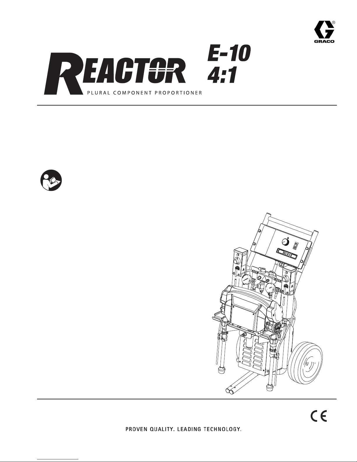
Instructions - Parts List
For spraying or dispensing 4:1 mix ratio materials, including
epoxies, polyurethane foam, and polyurea coatings.
Not for use in explosive atmospheres.
Important Safety Instructions
Read all warnings and instructions in this manual. Save these instructions.
313221A
See page 4 for a list of models and maximum working pressures.
Page 2

Contents
Related Manuals . . . . . . . . . . . . . . . . . . . .3
Models . . . . . . . . . . . . . . . . . . . . . . . . . . . .4
Warnings . . . . . . . . . . . . . . . . . . . . . . . . . . 5
Overview . . . . . . . . . . . . . . . . . . . . . . . . . . . 8
Keep Components A and B Separate . . . 8
Component Identification . . . . . . . . . . . . .9
Controls and Indicators . . . . . . . . . . . . . 10
Motor/Pump Control Function Knob . . . 10
STATUS Indicator . . . . . . . . . . . . . . . . . 10
Motor Power Switch/Circuit Breaker . . . 11
Heater Power Switch/Circuit Breaker . . 11
Heater Temperature Controls . . . . . . . . 11
Fluid Temperature Sensors and Displays .
11
Air Compressor Power Switch/Circuit
Breaker . . . . . . . . . . . . . . . . . . . . . .12
Air Compressor Controls . . . . . . . . . . . 12
Setup . . . . . . . . . . . . . . . . . . . . . . . . . . . . . 13
Startup of Heated Units . . . . . . . . . . . . . . 19
Spraying/Dispensing . . . . . . . . . . . . . . . . 20
Pause (Heated Units) . . . . . . . . . . . . . . . . 21
Pressure Relief Procedure . . . . . . . . . . . 22
Shutdown . . . . . . . . . . . . . . . . . . . . . . . . .22
Maintenance . . . . . . . . . . . . . . . . . . . . . . . 23
Flushing . . . . . . . . . . . . . . . . . . . . . . . . . .24
Troubleshooting . . . . . . . . . . . . . . . . . . . .26
Status Codes . . . . . . . . . . . . . . . . . . . .26
Troubleshooting Chart . . . . . . . . . . . . .29
Repair . . . . . . . . . . . . . . . . . . . . . . . . . . . .35
Before Beginning Repair . . . . . . . . . . . .35
Recirc/Spray Valves . . . . . . . . . . . . . . .36
Displacement Pump . . . . . . . . . . . . . . .37
Control Module . . . . . . . . . . . . . . . . . . .39
Fluid Heaters . . . . . . . . . . . . . . . . . . . .44
Pressure Transducers . . . . . . . . . . . . . .44
Drive Housing . . . . . . . . . . . . . . . . . . . .45
Cycle Counter Switch Replacement . . .46
Electric Motor . . . . . . . . . . . . . . . . . . . .47
Compressor . . . . . . . . . . . . . . . . . . . . .48
Motor Brushes . . . . . . . . . . . . . . . . . . .49
Fan . . . . . . . . . . . . . . . . . . . . . . . . . . . .49
Parts . . . . . . . . . . . . . . . . . . . . . . . . . . . . .50
Suggested Spare Replacement Parts . .56
Accessories . . . . . . . . . . . . . . . . . . . . . . .56
Dimensions . . . . . . . . . . . . . . . . . . . . . . . .58
Technical Data . . . . . . . . . . . . . . . . . . . . .59
Graco Standard Warranty . . . . . . . . . . . .60
Graco Information . . . . . . . . . . . . . . . . . .60
2 313221A
Page 3
Related Manuals
Related Manuals
The following manuals are for Reactor E-10 - 4:1components and accessories. Some are supplied with your package, depending on its configuration. Manuals are available at
www.graco.com.
Fluid Heater
Part
No. Description
311210 Instruction-Parts Manual (English)
Fusion Air Purge Plural Component Gun
Part
No. Description
309550 Instruction-Parts Manual (English)
Displacement Pump - White Material
Part
No. Description
311076 Instruction-Parts Manual (English)
Static Mixer Kit
Part
No. Description
313122 Instruction-Parts Manual (English)
313221A 3
Page 4

Models
Models
The model no., series letter, and serial no. are located on the back of the Reactor E-10. For faster
assistance, please have that information ready before calling Customer Service.
Maximum
Working
Pressure,
Reactor E10
4:1 Volts
* Electrical
Connection
psi
(MPa, bar)
256765 120
V
15 A cord
(motor)
15 A cord
(heaters)
15 A cord
(compressor)
2000
(14, 140)
* See page 14 for detailed electrical requirements.
4 313221A
Page 5
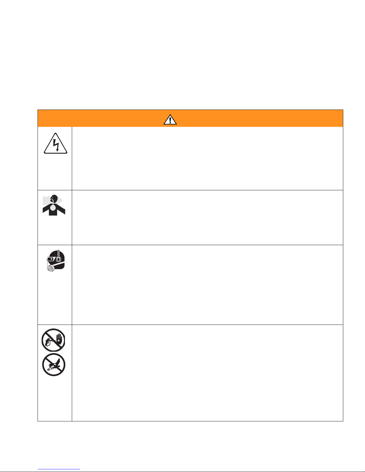
Warnings
Warnings
The following general warnings are for the setup, use, grounding, maintenance, and repair of this
equipment. Additional, more specific warnings may be found throughout the body of this manual
where applicable. Symbols appearing in the body of the manual refer to these general warnings.
When these symbols appear throughout the manual, refer back to these pages for a description
of the specific hazard.
WARNING
ELECTRIC SHOCK HAZARD
Improper grounding, setup, or usage of the system can cause electric shock.
• Turn off and disconnect power cord before servicing equipment.
• Use only grounded electrical outlets.
• Use only 3-wire extension cords.
• Ensure ground prongs are intact on sprayer and extension cords.
• Do not expose to rain. Store indoors.
TOXIC FLUID OR FUMES HAZARD
Toxic fluids or fumes can cause serious injury or death if splashed in the eyes or on
skin, inhaled, or swallowed.
• Read MSDS’s to know the specific hazards of the fluids you are using.
• Store hazardous fluid in approved containers, and dispose of it according to
applicable guidelines.
PERSONAL PROTECTIVE EQUIPMENT
You must wear appropriate protective equipment when operating, servicing, or when
in the operating area of the equipment to help protect you from serious injury, including eye injury, inhalation of toxic fumes, burns, and hearing loss. This equipment
includes but is not limited to:
• Protective eyewear
• Clothing and respirator as recommended by the fluid and solvent manufacturer
•Gloves
• Hearing protection
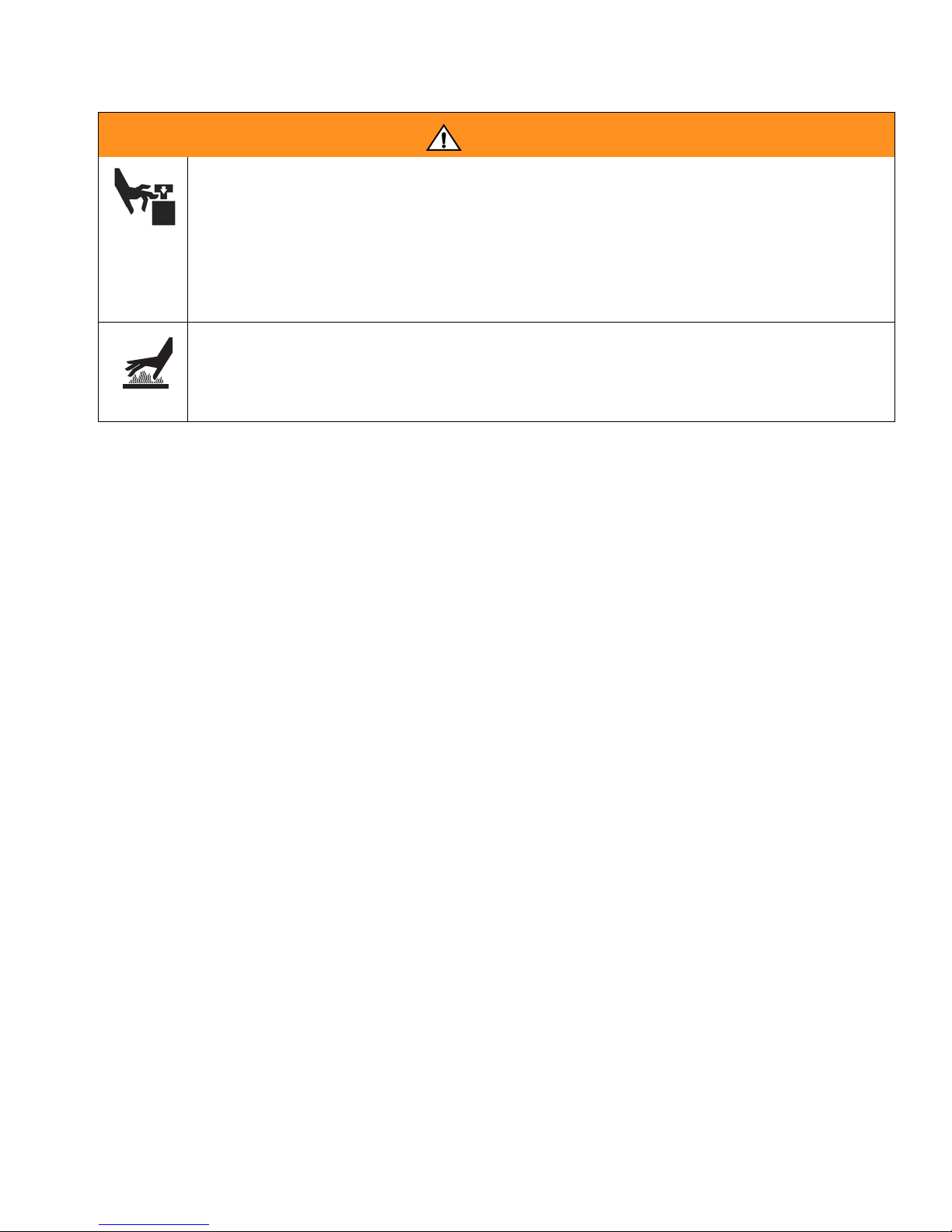
SKIN INJECTION HAZARD
High-pressure fluid from gun, hose leaks, or ruptured components will pierce skin.
This may look like just a cut, but it is a serious injury that can result in amputation.
Get immediate surgical treatment.
• Do not point gun at anyone or at any part of the body.
• Do not put your hand over the spray tip.
• Do not stop or deflect leaks with your hand, body, glove, or rag.
• Do not spray without tip guard and trigger guard installed.
• Engage trigger lock when not spraying.
• Follow Pressure Relief Procedure in this manual, when you stop spraying and
before cleaning, checking, or servicing equipment.
313221A 5
Page 6
Warnings
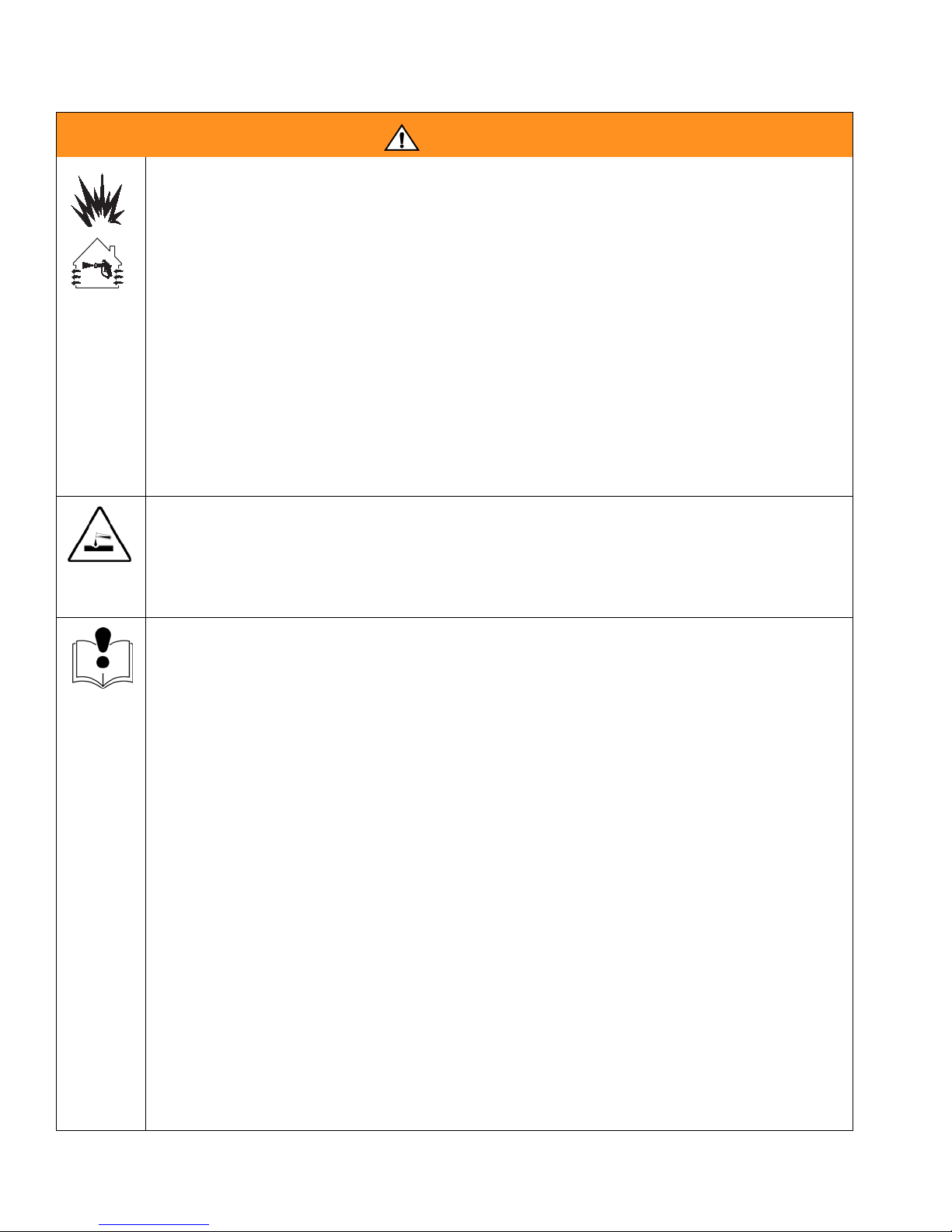
WARNING
FIRE AND EXPLOSION HAZARD
Flammable fumes, such as solvent and paint fumes, in work area can ignite or
explode. To help prevent fire and explosion:
• Use equipment only in well ventilated area.
• Eliminate all ignition sources; such as pilot lights, cigarettes, portable electric
lamps, and plastic drop cloths (potential static arc).
• Keep work area free of debris, including solvent, rags and gasoline.
• Do not plug or unplug power cords, or turn power or light switches on or off when
flammable fumes are present.
• Ground all equipment in work area. See Grounding instructions.
• Use only grounded hoses.
• Hold gun firmly to side of grounded pail when triggering into pail.
• If there is static sparking or you feel a shock, stop operation immediately. Do
not use equipment until you identify and correct the problem.
• Keep a fire extinguisher in the work area.
PRESSURIZED ALUMINUM PARTS HAZARD
Do not use 1,1,1-trichloroethane, methylene chloride, other halogenated hydrocarbon solvents or fluids containing such solvents in pressurized aluminum equipment.
Such use can cause serious chemical reaction and equipment rupture, and result in
death, serious injury, and property damage.
EQUIPMENT MISUSE HAZARD
Misuse can cause death or serious injury.
• This equipment is for professional use only.
• Do not leave the work area while equipment is energized or under pressure. Turn
off all equipment and follow the Pressure Relief Procedure in this manual when
equipment is not in use.
• Do not exceed the maximum working pressure or temperature rating of the lowest rated system component. See Technical Data in all equipment manuals.
• Use fluids and solvents that are compatible with equipment wetted parts. See
Technical Data in all equipment manuals. Read fluid and solvent manufacturer’s
warnings. For complete information about your material, request MSDS from distributor or retailer.
• Check equipment daily. Repair or replace worn or damaged parts immediately
with genuine Graco replacement parts only.
• Do not alter or modify equipment.
• Use equipment only for its intended purpose. Call your Graco distributor for information.
• Route hoses and cables away from traffic areas, sharp edges, moving parts, and
hot surfaces.
• Do not kink or over bend hoses or use hoses to pull equipment.
• Keep children and animals away from work area.
• Do not operate the unit when fatigued or under the influence of drugs or alcohol.
• Comply with all applicable safety regulations.
6 313221A
Page 7
Warnings
WARNING
MOVING PARTS HAZARD
Moving parts can pinch or amputate fingers and other body parts.
• Keep clear of moving parts.
• Do not operate equipment with protective guards or covers removed.
• Pressurized equipment can start without warning. Before checking, moving, or
servicing equipment, follow the Pressure Relief Procedure in this manual. Dis-
connect power or air supply.
BURN HAZARD
Equipment surfaces and fluid that’s heated can become very hot during operation.
To avoid severe burns, do not touch hot fluid or equipment. Wait until equipment/fluid has cooled completely.
313221A 7
Page 8

Overview
Overview
The Reactor E-10 is a portable, electric-powered, 4:1 mix ratio proportioner, for use with a
wide variety of coatings, foams, sealants, and
adhesives. Materials must be self-leveling and
pourable, and may be applied with impingement mix spray guns, disposable mixer guns,
or flush-type mix manifolds.
Reactor E-10 is siphon-fed from 5 gallon pails
that can be mounted on the unit.
Severe duty, positive displacement reciprocating piston pumps meter fluid flow to the gun for
mixing and applying. When set to recirculation
mode, Reactor E-10 will circulate fluids back to
the 5 gallon pails.
The Reactor E-10 includes separate thermostatically controlled heaters for each fluid. Digital displays show the temperatures of the two
fluids.
An electronic processor controls the motor,
monitors fluid pressures, and alerts the operator if errors occur. See STATUS Indicator,
page 10, for further information.
Reactor E-10 has two recirculation speeds,
slow and fast, and an adjustable pressure output.
Slow Recirculation
• Slow circulation results in a higher temperature transfer in the heater, so hoses and
gun heat up quicker.
• Good for touchup or low flow spraying, up
to moderate temperature.
• Not used to circulate full tanks up to temperature.
Fast Recirculation
• Use to support higher flow rates or higher
temperatures by preheating the tanks.
• Agitates fluid within tanks, to avoid heating
only the fluid at the top of the tank.
• Use for flushing.
Pressure Adjust
An air compressor provides and regulates air
pressure for the spray gun.
Automatically maintains selected pressure output for dispensing or spraying.
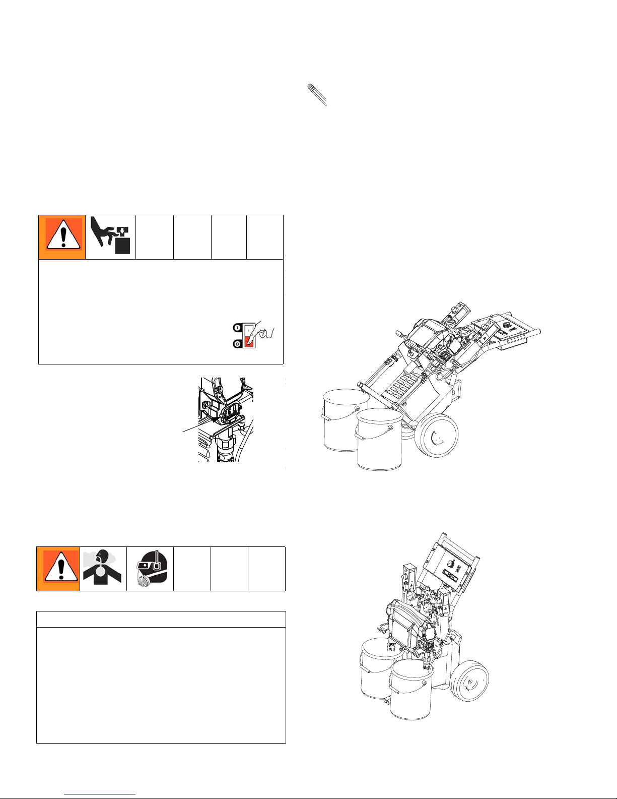
Keep Components A
and B Separate
CAUTION
To prevent cross-contamination of the equipment’s wetted parts, never interchange component A (white fluid) and component B (red
fluid) parts.
8 313221A
Page 9
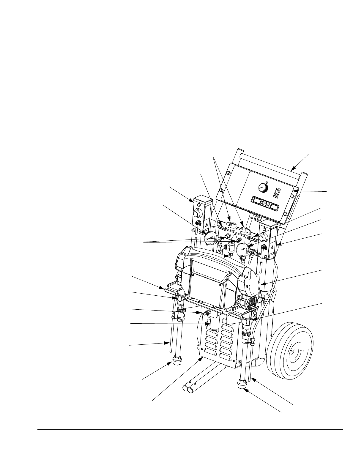
Component Identification
Key for FIG. 1
Component Identification
A Pump A
B Pump B
C Heater A
D Heater B
E Compressor
F Crossbar
G Pail Mounting Bracket
H Fluid Pressure Gauges
J Recirc/Spray and Overpressure Relief Valves
C
H
R
K Control Panel; see F
IG. 2, page 10
L Electric Motor and Drive Housings
M Suction Tubes
N Recirculation Tubes
P Air Line outlet
R Outlet Hose Connections
S Recirculation Tube Connections
T Fluid Temperature Sensors
U Air Filter/Moisture Separator
J
S
F
K
S
H
D
T
G
A
P
U
N
M
FIG. 1: Component Identification
L
B
E
N
M
313221A 9
Page 10
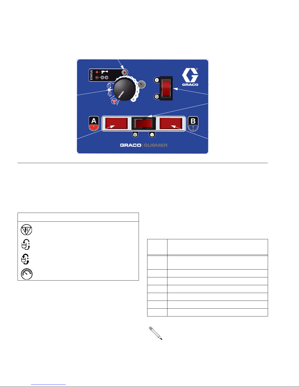
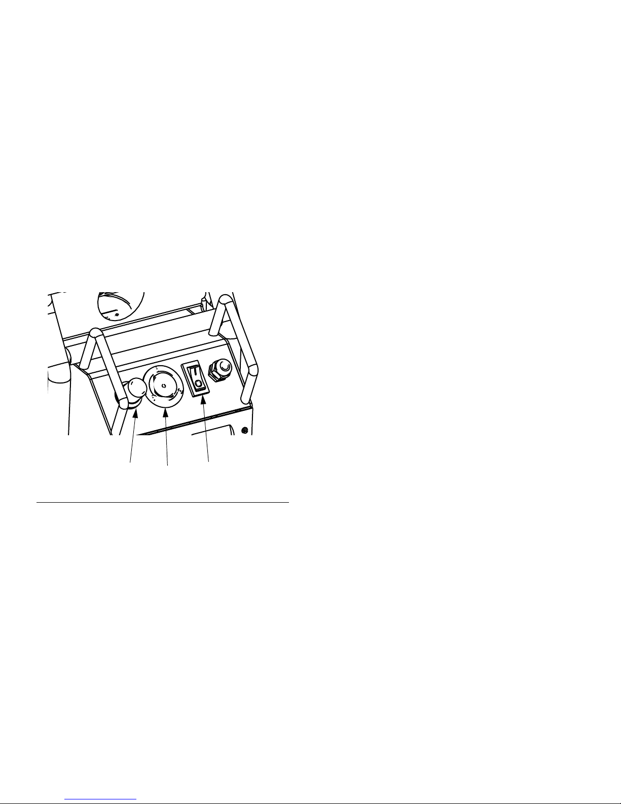
Controls and Indicators
ST
Controls and Indicators
CF
TD TD
FIG. 2. Controls and Indicators (heated unit shown)
Motor/Pump Control
• Indicator (ST) blinking: If error occurs, STA-
Function Knob
Use knob (CF) to select desired function.
Icon Setting Function
Stop/Park Stops motor and auto-
matically parks pumps.
Slow
Recirc
Fast Recirc Fast recirculation
Pressure
Adjust
STATUS Indicator
• Indicator (ST) steady on: Motor Power
switch is turned on and control board is
working.
Slow recirculation
speed.
speed.
Adjusts fluid pressure
to gun in spray mode.
Code
No. Code Name
1 Pressure imbalance between A and B
2 Unable to maintain pressure setpoint
3 Pressure transducer A failure
4 Pressure transducer B failure
5 Excessive current draw
6 High motor temperature
7 No cycle counter switch input
MP
HP
TI7016a
TUS indicator will blink 1 to 7 times to indicate status code, pause, then repeat. See
T
ABLE 1 for a brief description of status
codes. For more detailed information and
corrective action, see page 26.
Table 1: Status Codes
(see also the label on back of the control
enclosure)
sides
The default is to shut down if a status
code indication occurs. Codes 1 and 2
may be set to disable automatic shutdown if desired; see page 27. The other
codes are not settable.
10 313221A
Page 11
Controls and Indicators
Motor Power Switch/Circuit
Breaker
Switch (MP) turns power on to control board
and function knob. The switch includes a 20 A
circuit breaker.
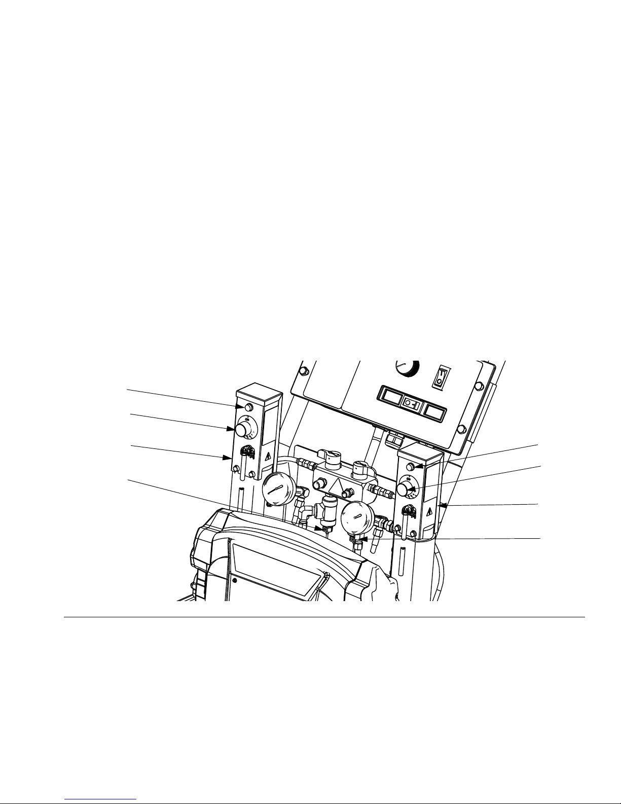
Heater Power Switch/Circuit
Breaker
See FIG. 2. Switch (HP) turns power on to
heater thermostats. The switch includes a 20 A
circuit breaker.
Heater Temperature Controls
See FIG. 3. Control knobs (HC) set temperature of component A and B heaters. Indicator
lights (HL) turn on when thermostats are heating, and off when heater reaches setpoint.
Fluid Temperature Sensors
and Displays
See FIG. 2. Fluid temperature sensors (T)
monitor actual temperature of component A
and B fluid going to spray gun. Temperatures
are then displayed (TD).
Unit is shipped set to °F. To change to °C, see
page 39.
HL
HC
C
T
IG. 3. Heater Temperature Controls
F
HL
HC
D
T
313221A 11
Page 12
Air Compressor Power
Switch/Circuit Breaker
Switch (CP) turns power on to compressor and
regulator. The switch includes a 20 A circuit
breaker.
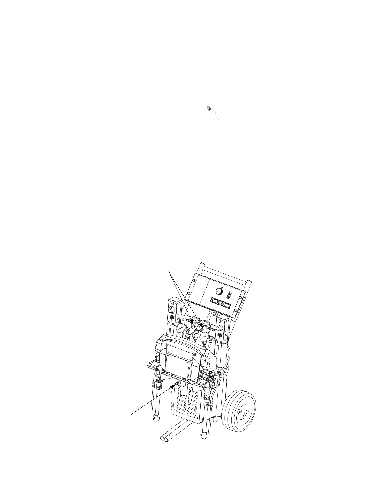
Air Compressor Controls
Pressure Gauge (PG) indicates set air pressure by regulator.
Regulator (AR) sets desired air pressure.
Controls and Indicators
FIG. 4
AR
PG CP
12 313221A
Page 13
Setup
Setup
1. Locate Reactor E-10
a. Locate Reactor E-10 on a level
surface.
b. Do not expose Reactor E-10 to
rain.
2. Electrical requirements
Improper wiring may cause electric shock or
other serious injury if work is not performed
properly. Have a qualified electrician perform
any electrical work. Be sure your installation
complies with all National, State and Local
safety and fire codes.
Connect Reactor E-10 to the correct power
source for your model. See TABLE 2. Models
with two power cords must be connected to
two separate, dedicated circuits. See FIG. 5.
3. Ground system
b. Generator (if used): follow your
local code. Start and stop generator with power cord(s) disconnected.
c. Spray gun: grounded through the
supplied fluid hoses, connected
to a properly grounded Reactor
E-10. Do not operate without at
least one grounded fluid hose.
d. Object being sprayed: follow your
local code.
e. Solvent pails used when flushing:
follow your local code. Use only
metal pails, which are conductive, placed on a grounded surface. Do not place pail on a
nonconductive surface, such as
paper, plastic, or cardboard,
which interrupts grounding continuity.
f. To maintain grounding continuity
when flushing or relieving pressure, hold a metal part of spray
gun firmly to the side of a
grounded metal pail, then trigger
gun.
The equipment must be grounded. Grounding
reduces the risk of static and electric shock by
providing an escape wire for the electrical current due to static build up or in the event of a
short circuit.
a. Reactor E-10: grounded through
power cord.
313221A 13
Page 14
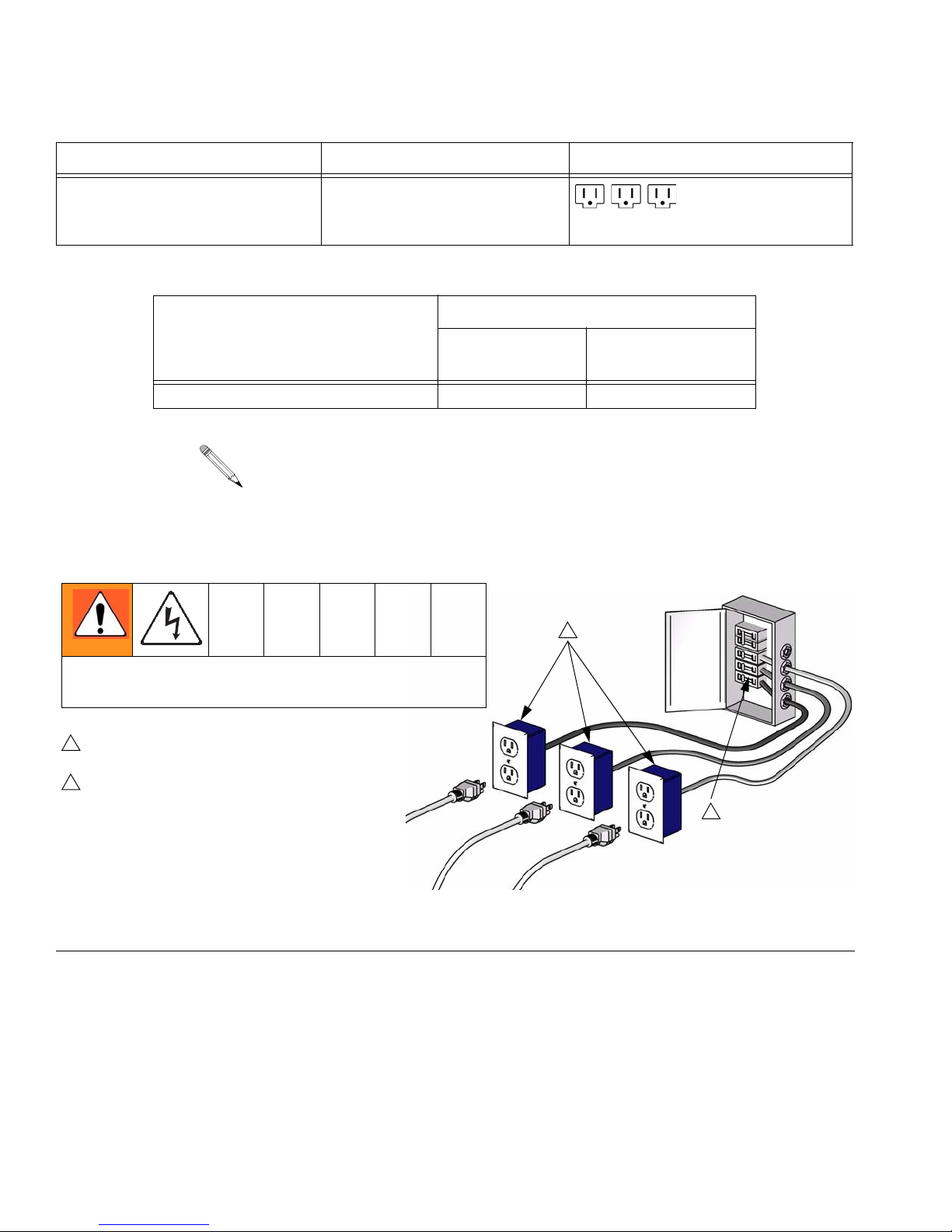
Table 2: Electrical Requirements
T
Model Required Power Source Power Cord Connector
Setup
120 V, 1 phase, 50/60 Hz,
three 15 ft (4.5 m) power cords,
Heated
Table 3: Extension Cord Requirements
Model
Two cord heated models AWG 14 AWG 12
Cords must be 3-conductor grounded, rated for your
environment.
Three separate, dedicated
circuits rated at minimum of
15 A each
Required Wire Size
Up to 50 ft (15
m) Up to 100 ft (30 m)
Three NEMA 5-15
1
To avoid electric shock, always unplug all cords
before servicing Reactor E-10.
1
Ensure no other high amp loads are connected
while running Reactor E-10.
2
To verify separate circuits, plug in Reactor E-10
or a worklight and cycle breakers on and off.
Heater Power
Motor Power
IG. 5. Use Three Separate Circuits
F
2
TI12383a
Compressor Power
14 313221A
Page 15
Setup
4. Connect fluid hoses
Connect fluid supply hoses to outlet
hose connections (R, FIG. 6). Fittings
are sized to prevent connection errors.
Connect other end of hoses to A and B
inputs of gun.
5. Connect gun air hose
Connect gun air hose to the gun air
input and to the air filter outlet (Z). If you
are using more than one hose bundle,
join the air hoses with the nipple (305)
provided with the hose bundle.
On heated units with Fusion guns, connect the supplied ball valve and
quick-disconnect coupler to the gun air
hose, then connect the coupler to the
gun air fitting.
6. Turn on air compressor
Turn on air compressor power. Set regulator to desired output pressure as indicated on the gauge.
Air Filter/Moisture Separator (Z) is
equipped with an automatic moisture
drain.
7. Flush before first use
The Reactor E-10 is tested with a plasticizer oil at the factory. Flush out the oil
with a compatible solvent before spraying. See page 24.
R
Z
FIG. 6. Hose Connections
313221A 15
Page 16
Setup
8. Fill wet-cups
Keep the felt washers in the pump
wet-cups saturated with Owens Corning
plasticizer; see Owens Corning Distributor. The lubricant creates a barrier
between the red fluid and the atmosphere.
Pump rod and connecting rod move during
operation. Moving parts can cause serious
injury such as pinching or amputation. Keep
hands and fingers away from wet-cup dur-
ing operation. Shut off Motor Power
before filling wet-cup.
Using a drill and mixing blade, mix filled or
separated materials in the pail. Material
left in the tanks overnight may need to be
remixed.
a. Open red and white fluid pails
and position in front of suction
tubes.
b. Stand behind unit and hold cross-
bar. Lean unit backwards until the
suction tubes are above the supply pails.
Fill wet-cups through slots
in plate, or loosen screws
and swing plate aside.
TI6985a
9. Install suction tube
CAUTION
To prevent cross-contamination of fluids and
equipment parts, never interchange component A and component B parts or containers.
Label one pail “A” and the other “B”, using
the labels provided. Always doublecheck
which material you have before placing suction tubes in pails.
A
B
c. Place suction tubes in pails.
A
B
16 313221A
Page 17
Setup
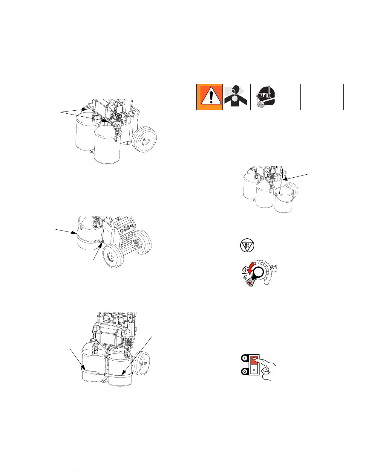
10. Mount pails
a. Insert pail handles on mounting
bracket (G).
G
A
b. Install one end of strap (SR)
through eye bolt (EB) on A side of
unit. Use second strap for B side.
11. Purge air and flush fluid from
lines
P
a. Remove both recirculation tubes
(N) from the pails and secure
B
each one in a dedicated waste
container (W).
N
A
B
W
SR
EB
c. Latch straps (SR) together in
front of pails.
SR
A
B
b. Set function knob to Stop/Park
.
c. Plug in power cord(s). See TABLE
2, page 14.
SR
d. Turn on Motor Power.
313221A 17
Page 18

e. Set Recirc/Spray valves to
Recirc.
f. Set function knob to Slow Recirc
or Fast Recirc .
O
g. When clean fluids exit both recir-
culation tubes (P), set function
Setup
knob to Stop/Park .
h. Replace recirculation tubes in
pails.
i. On nonheated units, purge the
hoses through the gun without a
static mixer installed.
For heated units, continue with Startup of
Heated Units, page 19.
Nonheated units are ready to spray/dispense. Go to Spraying/Dispensing, page
20.
18 313221A
Page 19

Startup of Heated Units
Equipment surfaces can become very hot.
To avoid severe burns:
• Do not operate Reactor E-10 without all
covers and shrouds in place.
• Do not touch hot fluid or equipment.
• Allow equipment to cool completely
before touching it.
• Wear gloves if fluid temperature exceeds
110°F (43°C).
1. Perform Setup, pages 13-18.
Startup of Heated Units
5. Circulate through heaters until tempera-
ture readouts display desired temperature.
6. Adjust heater control knobs as neces-
sary for a stable spray temperature.
2. Set function knob to Slow Recirc or
Fast Recirc .
OR
3. Turn on Heater Power.
4. Temporarily set heater control knobs to
maximum setting.
313221A 19
Page 20

Spraying/Dispensing
I
Air is supplied to spray gun with gun piston
safety lock and gun fluid manifold valves A
and B closed (if present).
Fusion
Spraying/Dispensing
4. Check fluid pressure gauges to ensure
proper pressure balance. If imbalanced,
reduce pressure of higher component
by slightly turning Recirc/Spray valve
for that component toward Recirc, until
gauges show balanced pressures. The
pressure imbalance alarm (Status Code
1) is inactive for 10 sec after entering
spray pressure mode, to allow time to
balance pressures.
n this example, B side
pressure is higher, so
use the B side valve to
balance pressures.
1. Set function knob to Stop/Park .
2. Set Recirc/Spray valves to Spray.
3. Turn function knob to Pressure Adjust
. Keep turning to the right until fluid
pressure gauges show desired pressure.
Watch gauges for 10 sec to be sure pressure holds on both sides and pumps are
not moving.
5. Open gun fluid manifold valves A and B
(impingement mix guns only).
On impingement guns, never open fluid
manifold valves or trigger gun if pressures
are imbalanced.
20 313221A
Page 21

Pause (Heated Units)
6. Disengage piston safety lock.
Fusion
7. Test spray onto cardboard or plastic
sheet. Verify that material fully cures in
the required length of time, and is the
correct color. Adjust pressure and temperature to get desired results. Equipment is ready to spray.
3. Set Recirc/Spray valves to Recirc until
temperature readouts come back up.
4. If you stop spraying for more than 2 min-
utes when using an impingement mix
gun, close gun fluid valves A and B.
Doing this will keep the internal parts of
the gun cleaner and prevent crossover.
Pause (Heated Units)
To bring the hose and gun back to spray
temperature after a brief break, use the following procedure.
1. Engage piston safety lock.
Fusion
2. Set function knob to Slow Recirc .
313221A 21
Page 22

Pressure Relief Procedure
Pressure Relief
Procedure
1. Engage piston safety lock.
Fusion
2. Set function knob to Stop/Park .
Shutdown
For longer breaks (more than 10 minutes),
use the following procedure. If you will be
shut down for more than 3 days, first see
Flushing, page 24.
1. Follow all steps of Pressure Relief Pro-
cedure, at left.
2. If using an impingement mix gun, close
gun fluid valves A and B. Doing this will
keep the internal parts of the gun
cleaner and prevent crossover.
3. Turn Recirc/Spray valves to Recirc.
Fluid will be dumped to pails. Pumps will
move to the bottom of their stroke.
Ensure gauges drop to 0.
3. Shut off Heater Power (heated units
only).
4. Shut off Motor Power.
5. Shut off Compressor Power.
6. Remove pails from mounting bracket.
22 313221A
7. Refer to your separate gun manual and
perform the Shutdown procedure.
Page 23

Maintenance
• Check pump wet-cups fluid level daily, page
16.
• Do not overtighten packing nut/wet-cup.
Throat u-cup is not adjustable.
• Generally, flush if you will shutdown for
more than three days. Flush more often if
material is moisture sensitive and humidity
is high in the storage area, or if material
may separate or settle out over time.
• If using an impingement mix gun, close gun
fluid valves A and B when not spraying.
Doing this will keep the internal parts of the
gun cleaner and prevent crossover. Clean
gun mix chamber ports and check valve
screens regularly. See gun manual.
Maintenance
• If using an Fusion Air Purge impingement
mix gun, always grease the gun after use
until purge air carries grease mist out the
front of the gun. Use Part No. 117773
Grease. See gun manual 309550.
313221A 23
Page 24

Flushing
Flush equipment only in a well-ventilated
area. Do not spray flammable fluids. Do not
turn on heaters while flushing with flammable solvents.
• Generally, flush if you will be shut down for
more than 3 days. Flush more often if material is moisture sensitive and humidity is
high in the storage area, or if material may
separate or settle out over time.
• Flush out old fluid with new fluid, or flush
out old fluid with a compatible solvent
before introducing new fluid.
• Use the lowest possible pressure when
flushing.
Flushing
2. Set function knob to Stop/Park .
3. Shut off Heater Power (heated units
only). Allow system to cool.
4. Unlatch straps and remove A and B
pails from mounting bracket. Stand
behind unit and hold crossbar. Lean unit
backwards to remove suction tubes from
A and B fluid pails.
• Always leave some type of fluid in system.
Do not use water.
• For long term storage, flush out the solvent
with a storage fluid such as Bayer Mesamoll plasticizer or, at minimum, clean motor
oil.
1. Engage piston safety lock. Close fluid
valves A and B. Leave air on.
Fusion
A
B
5. Fill two pails with 1-2 gal. (3.8-7.6 l) of
solvent recommended by your material
manufacturer. Insert suction tubes in
solvent pails (SP).
24 313221A
Page 25

Flushing
6. Disconnect recirculation tube (N) and
insert in waste container (W).
N
SP
SP
W
7. Turn Recirc/Spray valves to Recirc.
8. Set function knob to Fast Recirc .
Pump solvent through system to waste
containers.
To flush gun, refer to gun instruction
manual.
Purge Gun Hoses
Disconnect hoses from gun and secure
back into the tanks for thorough cleaning
with solvent.
• Turn Recirc/Spray valve A to Spray.
• Open gun into waste container A.
• Set function knob to Slow Recirc
until hose is flushed.
• Set function knob to Stop/Park .
• Repeat for B side.
9. When nearly clear solvent comes from
recirculation tubes, set function knob to
Stop/Park . Place recirculation
tubes in solvent pails.
10. Set function knob to Fast Recirc .
Circulate solvent through system for
10-20 minutes to ensure thorough
cleaning.
11. Set function knob to Stop/Park .
12. Solvent flushing is a two step process.
Go back to step 4, drain solvent, and
flush again with fresh solvent.
13. Leave unit filled with solvent, plasticizer,
or reprime with new material.
Never leave the unit dry unless it has
been disassembled and cleaned. If fluid
residue dries in the pumps, the ball
checks may stick the next time you use
the unit.
313221A 25
Page 26

Troubleshooting
I
Troubleshooting
Status Codes
Determine the status code by counting the
number of times the status indicator (ST)
blinks.
ST
TI7016a
Status Code 1: Pressure Imbalance
The unit does not check for pressure
imbalance at setpoints less than 250 psi
(1.75 MPa, 17.5 bar).
n this example, B side
pressure is higher, so
use the B side valve to
balance pressures.
Turn Recirc/Spray valve only enough to
balance pressure. If turned completely, all
pressure will bleed off.
3. Check fluid inlet strainers (51a, page 23)
and fluid filters at gun.
4. Clean or change restrictor at mixer manifold if using disposable mixer gun kit.
Status Code 2: Pressure Deviation
from Setpoint
The unit does not check for pressure
deviation at setpoint less than 400 psi
(2.8 MPa, 28 bar).
The unit does not check for pressure
imbalance for 10 sec after entering pressure mode.
Unit senses pressure imbalance between components A and B, and warns or shuts down,
depending on settings of DIP switches 1 and 2.
To turn off automatic shutdown and/or tighten
pressure tolerances for status code 1, see Sta-
tus Code 1 and 2 Settings on page 27.
1. Check fluid supply of lower pressure component and refill if necessary.
2. Reduce pressure of higher component by
slightly turning Recirc/Spray valve for that
component toward Recirc, until gauges
show balanced pressures.
Unit senses pressure deviation from setpoint,
and warns or shuts down, depending on settings of DIP switches 3 and 4. If equipment
cannot maintain enough pressure for a good
mix with an impingement mix gun, try using a
smaller mix chamber or nozzle.
To turn off automatic shutdown and/or tighten
pressure tolerances for status code 2, see Sta-
tus Code 1 and 2 Settings on page 27.
26 313221A
Page 27

Troubleshooting
ON
Status Code 1 and 2 Settings
OFF
1. Locate switch SW2 on the control board,
page 43.
2. Set the four DIP switches to the desired
F
IG. 7. DIP Switch (SW2) Settings
positions. See FIG. 7 and TABLE 4 on page
27.
Table 4: Status Code 1 and 2 Settings
DIP Switch and Function Left
DIP Switch 1
If selected, causes shutdown or displays a warning if
there is a pressure imbalance exceeds selection made in
DIP Switch 2
DIP Switch 2
If selected, causes shutdown if A and B pressure imbal-
ance is greater than
If selected, causes warning if A and B pressure imbalance is greater than
DIP Switch 3
If selected, causes shutdown or displays a warning due to
deviation of pressure from setpoint exceeds selection
made in DIP Switch 4
DIP Switch 4
Causes warning if deviation of pressure from setpoint is
greater than
WARNING SHUTDOWN
500 psi (3.5 MPa, 35
bar)
(60% if < 800 psi [5.6
MPa, 56 bar] running)
300 psi (2.1 MPa, 21
bar)
(50% if < 800 psi [5.6
MPa, 56 bar] running)
WARNING SHUTDOWN
300 psi (2.1 MPa, 21
bar)
(25% if < 800 psi [5.6
MPa, 56 bar])
1
2
3
4
TI7023a
1
2
3
4
(Default)
TI7024a
Right (default
setting)
800 psi (5.6 MPa, 56
bar)
(70% if < 800 psi [5.6
MPa, 56 bar] running)
500 psi (3.5 MPa, 35
bar)
(60% if < 800 psi [5.6
MPa, 56 bar] running)
500 psi (3.5 MPa, 35
bar)
(40% if < 800 psi [5.6
MPa, 56 bar])
Status Code 3: Transducer A Failure
1. Check transducer A electrical connection
(J3) at board, page 43.
2. Reverse A and B transducer electrical connections at board, page 43. If error moves
to transducer B (Status Code 4), replace
transducer A, page 44.
313221A 27
Status Code 4: Transducer B Failure
1. Check transducer B electrical connection
(J8) at board, page 43.
2. Reverse A and B transducer electrical connections at board, page 43. If error moves
to transducer A (Status Code 3), replace
transducer B, page 44.
Page 28

Troubleshooting
Status Code 5: Excessive Current
Draw
Shut off unit and contact distributor before
resuming operation.
1. Locked rotor; motor unable to turn. Replace
motor, page 47.
2. Short on control board. Replace board,
page 42.
3. Worn or hung up motor brush causing arcing of brush at commutator. Replace
brushes, page 49.
Status Code 6: High Motor
Temperature
Motor is running too hot.
1. Motor temperature too high. Reduce pressure duty cycle, gun tip size, or move Reactor E-10 to a cooler location. Allow 1 hour
for cooling.
2. Check fan operation. Clean fan and motor
housing.
Status Code 7: No Cycle Counter
Switch Input
Have not received input from cycle counter
switch for 10 seconds after selecting Recirc
mode.
1. Check cycle counter switch connection to
board (J10, pins 5, 6), page 43.
2. Check that magnet (224) and cycle counter
switch (223) are in place under B side
motor end cover (227). Replace if necessary.
28 313221A
Page 29

Troubleshooting Chart
PROBLEM CAUSE SOLUTION
Reactor E-10 does not operate. No power. Plug in power cord.
Cycle Motor Power off ,
then on to reset breaker.
Troubleshooting
Motor does not operate. Power turned on with function
knob set to a run position.
Loose connection on control
board.
Worn brushes. Check both sides. Replace
Broken or misaligned brush
springs.
Brushes or springs binding in
brush holder.
Shorted armature. Replace motor, page 47.
Check motor commutator for burn
spots, black pitting, or other damage.
Failed control board. Replace board. See page 42.
Fan not working. Loose fan cable. Check that cable is connected at
Defective fan. Test and replace if necessary,
Pump output low. Plugged fluid inlet strainer. Clear, see page 23.
Plugged disposable mixer. Clean or replace.
Leaking or plugged piston valve
or intake valve in displacement
pump.
One side doesn’t come up to
pressure in spray mode.
Dirty or damaged Recirc/Spray
valve.
Plugged fluid inlet strainer. Clear, see page 23.
Pump intake valve plugged or
stuck open.
Set function knob to Stop/Park
, then select desired func-
tion.
Check connection at J11 (120 V).
See page 42.
brushes worn to less than 1/2 in.
(13 mm), see page 49.
Realign or replace, page 49.
Clean brush holder and align
brush leads for free movement.
Remove motor. Have motor shop
resurface commutator, or replace
motor, page 47.
fan and at J9 on control board.
See pages 49 and 42.
page 49.
Check valves. See pump manual.
Clean or repair, page 36.
Clean pump intake valve. See
page 37.
313221A 29
Page 30

PROBLEM CAUSE SOLUTION
Troubleshooting
Pressure is higher on one side
when setting pressure with function knob.
Pump intake valve partially
plugged.
Air in hose. Fluid is compressible. Purge air from hose.
Unequal size hoses or unequal
hose construction.
Pressures are not balanced when
Unequal viscosities. Change temperature setting to
running, but pressure is generated and holds on both strokes.
Restriction on one side. Clean mix module or restrictor at
Fluid leak in pump packing nut
Worn throat seals. Replace. See pump manual.
area.
Pressure doesn’t hold when
stalled against gun in spray
mode.
Leaking Recirc/Spray valve. Repair, page 36.
Leaking piston valve or intake
valve in displacement pump.
Leaking gun shutoff. Repair. See gun manual.
Pressure is higher on B side dur-
ing startup of recirculation, especially in High Recirc mode.
This is normal. Component B is
typically higher viscosity than
component A until the material is
heated during recirculation.
One gauge shows half as many
Loss of pressure on downstoke. Intake valve is leaking or not clospulses as the other when pumps
are cycling.
Loss of pressure on upstoke. Piston valve is leaking or not clos-
Status indicator (red LED) not lit. Motor Power switch off.
Clean pump intake valve. See
page 37.
Use matching hoses, or balance
pressures before spraying.
balance viscosities.
Change restrictor at mix point to
balance back pressure.
mix manifold.
Clean gun check valve screens.
Repair. See pump manual.
No action required.
ing. Clean or replace valve; see
page 37.
ing. Clean or replace valve or
packings; see page 37.
Cycle Motor Power off ,
A side rich; lack of B side. A side gauge is low. B side restriction downstream of
30 313221A
then on to reset breaker.
Loose indicator cable. Check that cable is connected at
J10 pins 1 (red) and 2 (black) on
control board. See page 42.
Failed control board. Replace board. See page 42.
gauge. Check gun check valve
screen, mix module, or mix manifold restrictor.
B side gauge is low. B side material supply problem.
Check B side inlet strainer and
pump intake valve.
Page 31

Troubleshooting
PROBLEM CAUSE SOLUTION
B side rich; lack of A side. A side gauge is low. A side material supply problem.
Check A side inlet strainer and
pump intake valve.
B side gauge is low. A side restriction downstream of
gauge. Check gun check valve
screen, mix module, or mix manifold restrictor.
No temperature display. Loose display cables on control
board.
Failed control board (displays get
power from control board).
Check cable connections to each
display, page 42.
Remove access panel. Check if
board LED is lighted. If not,
replace board, page 42.
Inadequate power to control
board.
Check that power supply meets
requirements.
Loose power cable. Check cable connections, page
42.
Motor Power switch circuit
breaker tripped.
Display is powered from Motor
Power circuit breaker. Cycle Motor
Power off , then on
to reset breaker.
Wrong temperature displayed. °F/°C switch in wrong position. Set switch, see page 39.
Temperature displays do not
match at ambient temperature.
Displays need calibration. Turn calibration screw on back of
displays to correct reading, see
page 39.
313221A 31
Page 32

PROBLEM CAUSE SOLUTION
Troubleshooting
No heat, and heater indicator light
is off.
Heater Power shut off, or circuit
breaker tripped.
Cycle Heater Power off ,
then on to reset circuit
breaker.
Bad thermostat. With power on, check for continu-
ity at clicks of heater control knob.
To replace thermostat, see
311210.
Bad overtemperature sensor (this
is a high temperature limit fuse
and must be replaced if blown).
With power on, check for continuity at overtemperature sensor. To
replace sensor, see 311210.
Loose heater cable connections. Check connections at Heater
Power switch. See F
IG. 12, page
43.
No heat, but heater indicator light
is on.
Bad heater cartridge. Check for continuity at heater car-
tridge connections: 16-18.6 ohms
for 120 V.
Heater on one side shuts off early
or continuously during recirculation.
Y-strainer is plugged on that side. Clean or replace strainer, page
23.
Fluid inlet valve (52) closed. Open valve.
B side pump is not priming Running pump too fast. Put finger over recirculation tube
Piston ball check is stuck in open
position.
while running, to build pressure,
and release. Repeat as necessary.
Low air output at gun Air valve at gun may be closed. Turn air valve counter-clockwise
to open.
Sprayer air regulator may be
closed.
Pull to unlock and turn air regulator clockwise to open.
Air connections may be loose. Check all connections for leaking
air.
Damaged (leaking) air supply
Replace air supply hose.
hose.
Air intake filter clogged. Clean or replace air intake filter
kit.
Mechanical air unloader stuck
Replace mechanical air unloader.
open.
Electrical air unloader stuck open. Replace electrical air unloader.
32 313221A
Page 33

Troubleshooting
PROBLEM CAUSE SOLUTION
Air compressor does not run Power is not on. Turn compressor power on.
Voltage to compressor below 105
Vac for 120 Vac.
Try another outlet. Reduce extension cord length or increase
extension cord gauge.
Loose power connections. Verify all connections are firm.
Excessive head pressure (com-
pressor hums)
Moisture frozen in air supply line.
Wait for air pressure to bleed to
zero.
Electrical air unloader stuck
closed. Replace electrical air
unloader.
Open air regulator; install air line.
Complete Setup on page 13.
Compressor thermal switch is
open. Ensure ambient tempera-
Move sprayer to shaded, cooler
area.
ture is below 115°F (46°C).
Low compressor performance Worn compressor; replace com-
pressor with Compressor Service
Kit 256779.
313221A 33
Page 34

Troubleshooting
34 313221A
Page 35

Repair
Before Beginning Repair
Repairing this equipment requires access to
parts which may cause electric shock or
other serious injury if work is not performed
properly. Have a qualified electrician connect
power and ground to main power switch terminals, see page 13. Be sure to shut off all
power to the equipment before repairing.
1. Flush if possible, see page 24. If not possible, clean all parts with solvent immediately
after removal.
Repair
2. Set function knob to Stop/Park .
3. Shut off Motor Power. Disconnect power
supply.
4. Shut off Heater Power. Allow equipment to
cool before repairing.
5. Relieve pressure, page 22.
313221A 35
Page 36

Recirc/Spray Valves
Repair
Heated Models
1. See Before Beginning Repair, page 35.
Relieve pressure, page 22.
2. See FIG. 8. Disassemble Recirc/Spray
valves. Clean and inspect all parts for damage. Ensure that the seat (503a) and gasket (503b) are positioned inside each valve
cartridge (503).
3. Apply PTFE pipe sealant to all tapered pipe
threads before reassembling.
4. Reassemble in reverse order, following all
notes in FIG. 8.
506
502
510
501
509
508
507
1
Torque to 250 in-lb (28 N•m).
2
Use blue threadlocker on valve cartridge threads into manifold.
3
Part of item 503.
505
504
503
503a
503b
1
2
3
3
510
FIG. 8. Recirc/Spray Valves
36 313221A
Page 37

Repair
Displacement Pump
A side displacement pump repair and
parts information is included in
manual 311076, which is supplied
with your unit.
Use dropcloth or rags to protect
Reactor E-10 and surrounding area
from spills.
1. See Before Beginning Repair, page 35.
Relieve pressure, page 22.
To Remove Suction Tube
To Remove Intake Valve Only
If pump is not generating any pressure,
the intake ball check may be stuck closed
with dried material.
If the pump is not generating pressure on
the downstroke, intake ball check may be
stuck open.
Either of these conditions can be serviced
with the pump in place.
2. Disconnect suction tube.
3. Remove intake valve by hitting ears (E)
firmly right-to-left with a non-sparking hammer. Unscrew from pump. See manual
311076 for repair and parts.
1. Loosen nut (34) and remove suction tube
(31).
E
30
32
31
33
34
35
313221A 37
Page 38

To Remove Entire Pump Assembly
4. Disconnect suction tube. See page 37. Also
disconnect steel outlet tube (16) from
heater inlet.
Repair
16
5. Remove pump rod cover (222). Push clip
up in back and push pin (217) out. Loosen
locknut (218) by hitting firmly right-to-left
with a non-sparking hammer. Unscrew
pump. See manual 311076 for pump repair
and parts.
6. Install pump in reverse order of disassembly, following all notes in FIG. 9. Clean
strainer (51). Reconnect suction tube and
outlet (D) lines.
7. Tighten fluid outlet fitting (D), then tighten
locknut (218) by hitting firmly with a
non-sparking hammer.
8. Set function knob to Slow Recirc .
Purge air and prime. See page 17.
217
E
2
1
218
1
Flat side faces up. Tighten by hitting
firmly with non-sparking hammer.
222
207
D
2
51
2
Lubricate threads with ISO oil or grease.
FIG. 9. Displacement Pump
38 313221A
Page 39

Repair
Control Module
Change Display Temperature Units
(°F/°C)
Unit is shipped with temperature displays set
to °F.
1. Shut off Motor Power. Disconnect power
supply.
2. Remove access cover (39) from back of
control module.
Replace Temperature Display and
Sensor (Heated Units Only)
1. See Before Beginning Repair, page 35.
Relieve pressure, page 22.
2. Remove temperature sensor (424):
a. Loosen setscrew (22) on thermowell
housing (21). See FIG. 10 on page 40.
b. Pull sensor (424) out of thermowell
housing.
c. Work sensor and wire out of cable
channel between tanks. It may be easier to remove one tank. See page 36.
3. See FIG. 11. Locate slide switch (FC) at
right edge of each temperature display
board. Unit is shipped set to °F (down). To
change to °C, move both switches to up
position.
Calibrate Temperature Displays
1. Remove access cover (39) from back of
control module.
2. See FIG. 11. Locate calibration screw (CS)
at upper right corner of each temperature
display board. Turn screw slightly to correct
temperature display.
Temperature displays do not read lower
than 50°F (10°C).
3. Remove access cover (39) from back of
control module.
4. Disconnect temperature display power
cable from J14 or J15 at bottom left of control board (406).
5. Remove four screws from rear panel studs
and remove temperature display (403) from
front plate (401).
6. Remove screw and nut (409) holding display to plate (403).
7. Pull sensor cable through split in bushing
(411).
313221A 39
Page 40

Repair
8. Reassemble in reverse order. Mount temperature display so Heater Power switch off
(0) position is at left when facing control
panel.
22
21
424
TI7067a
FIG. 10. Temperature Sensor
horizontal. Position knob (416) so pointer
(P) faces up. Install knob on shaft so slot
(S) engages alignment pin in knob. Push
knob onto shaft against detent spring
before tightening setscrews (416a).
7. Reconnect potentiometer wires to J2 as
shown in F
IG. 12.
Replace Function
Knob/Potentiometer
1. See Before Beginning Repair, page 35.
Relieve pressure, page 22.
2. Remove access cover (39) from back of
control module.
3. Disconnect potentiometer wires from J2 on
control board (406). See FIG. 12.
4. See F
and pull function knob (416) off potentiometer (404) shaft.
5. Remove nut (N, part of 404) and detent
plate (415).
IG. 11. Remove two setscrews (416a)
6. Install new potentiometer (404) in reverse
order. Position potentiometer so slot (S) is
40 313221A
Page 41

Detail of Function Knob/Potentiometer
415
N
P
404
Repair
TI7076a
409
*424
*403
416a
FC
CS
416
*402
416a
421
424*
CS
FC
401
410
S
410*
404
411
402
408
407
412
413
405
416a
416
416a
N
415
417
406
FIG. 11. Control Module (Heated Model Shown)
313221A 41
* These items are not included on the nonheated display.
TI6979a
Page 42

Repair
Control Board
Power Bootup Check
There is one red LED (D11) on the
board. Power must be on to check. See
F
IG. 12 for location. Function is:
• Startup: 1 blink for 60 Hz, 2 blinks for
50 Hz.
• Motor running: LED on.
• Motor not running: LED off.
• Status code (motor not running):
LED blinks status code.
Control Board Replacement
Table 5: Control Board Connectors
(see FIG. 12)
Board
Jack Pin Description
J1 n/a Main power from breaker
J2 n/a Function knob
J3 n/a Transducer A
J4 n/a Motor power (230 V units)
J7 1, 2 Motor thermal overload signal
J8 n/a Transducer B
J9 n/a Fan
J10 1, 2 Status indicator
3, 4 Not used
5, 6 Cycle switch signal
7-8 Jumpered
9-10 Jumpered
J11 n/a Motor power (120 V)
J14 n/a B temperature display
J15 n/a A temperature display
Check motor before replacing board.
See Electric Motor, page 47.
1. See Before Beginning Repair, page 35.
Relieve pressure, page 22.
2. Remove access cover (39) at back of control module to expose control board (406).
3. Disconnect all cables and connectors from
board. Remove two jumper wires (413)
from J10 pins 7-8 and 9-10.
4. Remove screws (408) and remove board
from control module.
5. Install new board in reverse order.
Apply thermal compound between the
square steel piece on the back of the
board and the main aluminum plate.
Order Part No. 110009 Thermal Compound.
42 313221A
Page 43

Repair
Motor
Cycle
Counter
Black Twin Flat Cable
Fan
Status
Indicator
Black Sheath
Red
Black
LINE
P1
Ye l l o w
Ye l l o w
Red
Black
Jumper
Jumper
Motor Power
Black
White
P1
P2
On/Off
(20 A
Breaker)
Single Cord Models Only
LINE
Heater Power
On/Off
(20 A
Breaker)
P2
Heater
A
Heater
B
J1
J9
J11 (120 V Board)
J4
J11
J4 (240 V Board)
J7
CONTROL BOARD
249434 (120 V)
Function
Knob
249432 (240 V)
not used
1
2
3
4
5
J10
6
7
8
9
10
J15J14
1
2
3
4
D11
ONOFF
SW2 (see page 27
to adjust settings)
not used
Black
Red
White
J2
Black Sheath
J3J8
2 pin red connectors2 pin red connectors
Gray SheathGray Sheath
Pressure Transducer A
Calibration
Screw
°C
Temperature
Display B
°F
Temperature
Sensor B
Calibration
Screw
°C
Temperature
Display A
Gray Sheath
°F
Temperature
Sensor A
Black Phone Cable and Plug
Pressure Transducer B
FIG. 12. Control Module Wiring Connections
313221A 43
Page 44

Fluid Heaters Pressure Transducers
Fluid heater repair and parts
information is included in manual
311210, which is supplied with heated
units.
1. See Before Beginning Repair, page 35.
To replace a pressure transducer, see
at right.
Relieve pressure, page 22.
2. Remove access cover (39) at back of control module to expose control board (406).
3. Disconnect transducer cables from J3 and
J8 at board; see F
IG. 12, page 43. Reverse
A and B connections and check if status
code follows the bad transducer, page 27.
Repair
1. See Before Beginning Repair, page 35.
Relieve pressure, page 22.
2. Control section of heater can be repaired in
place. Remove heater to clean fluid section.
See manual 311210 for heater repair and
parts.
4. Reconnect good transducer to proper connector. Disconnect failed transducer from
board, and unscrew from base of fluid
heater (heated units) or transducer manifold (nonheated units).
5. Install o-ring (60) on new transducer (58),
F
IG. 13.
6. Install transducer in heater or manifold.
Mark board end of cable with tape
(red=transducer A, blue=transducer B).
7. Route cable through channel to control
module.
8. Connect transducer cable at board; see
FIG. 12, page 43.
58
60
44 313221A
Heated Units
IG. 13. Transducers
F
TI7026a
Page 45

Repair
Drive Housing
Removal
1. See Before Beginning Repair, page 35.
Relieve pressure, page 22.
2. Remove screws (207) and end covers (221,
227), FIG. 14.
Examine connecting rod (216). If rod
needs replacing, first remove the pump
(219), page 37.
CAUTION
Do not drop gear reducer (214) and crankshaft (210) when removing drive housing
(215). These parts may stay engaged in
motor end bell (MB) or may pull away with
drive housing.
3. Disconnect pump inlet and outlet lines.
Remove screws (220) and pull drive housing (215) off motor (201) Connecting rod
(216) will disengage from crankshaft (210).
B side crankshaft (210) includes the
cycle counter magnet (224). When
reassembling, be sure to install crankshaft with magnet on B side.
If replacing crankshaft, remove magnet
(224). Reinstall magnet in center of offset shaft on new crankshaft. Position
shaft in Park position.
2. Install bronze bearings (211, 213) in drive
housing (215), as shown.
3. Install bronze bearings (209, 211) and steel
washer (208) on crankshaft (210). Install
bronze bearing (213) and steel washer
(212) on gear reducer (214).
4. Install gear reducer (214) and crankshaft
(210) into motor end bell (MB).
Crankshaft (210) must be in line with
crankshaft at other end of motor. Pumps
will move up and down together.
If connecting rod (216) or pump (219)
were removed, reassemble rod in housing and install pump, page 37.
5. Push drive housing (215) onto motor (201).
Install screws (220).
4. Examine crankshaft (210), gear reducer
(214), thrust washers (208, 212), and bearings (209, 211, 213).
Installation
1. Apply grease liberally to washers (208,
212), bearings (209, 211, 213), gear
reducer (214), crankshaft (210), and inside
drive housing (215). Grease is supplied
with replacement parts kits.
313221A 45
6. Install drive housing covers (221 on A side,
227 on B side) and screws (207). Pumps
must be in phase (both at same position in
stroke).
Page 46

Cycle Counter Switch Replacement
B side drive housing cover (227) includes the cycle counter
switch (223), mounted in the cover. When reassembling, be
sure to install cover with switch on B side.
223
0.6 in. (15.2 mm)
from inside edge
1.0 in. (25.4 mm)
from inside bottom
edge
TI7028a
Repair
221
222
207
220
218
219
211
(bronze)
215
216
207
209
(bronze)
210
208
(steel)
214
213
(bronze)
217
234
206
207
227
229
201
212
(steel)
213
(bronze)
1
Crankshaft must be in line with crankshaft
at other end of motor, so pumps move up and down in unison.
FIG. 14. Drive Housing
46 313221A
Page 47

Electric Motor
Repair
Test Motor
If motor is not locked up by pumps, it can be
tested using a 9 V battery. Open recirculating
valves, disconnect J4 or J11 from control
board, see FIG. 12, page 43. Touch jumpers
from battery to motor connections. Motor
should turn slowly and smoothly.
Removal
If replacing a component with electrical
cabling, remove one supply tank, page
36.
1. See Before Beginning Repair, page 35.
Relieve pressure, page 22.
e. Thread motor power switch harness out
bottom of control module and cable
channel, to free motor.
CAUTION
Motor is heavy. Two people may be required
to lift.
5. Remove screws holding motor to bracket.
Lift motor off unit.
Installation
1. If replacing motor, install fan assembly and
fan mount threaded bushing on new motor.
2. Place motor and fan on unit. Thread motor
switch harness into control module.
3. Fasten motor with screws underneath. Do
not tighten yet.
2. Remove four screws (207) and shroud
(206). See FIG. 14.
3. Remove drive housing/pump assemblies,
page 45.
4. Disconnect motor cables as follows:
a. Find control board at back of control
module, see F
IG. 12, page 43.
b. Unplug motor power connector from
J11 (120 V units).
c. Unplug motor temp switch harness from
connector J7.
d. Unplug cable (37) from fan (202). See
F
IG. 18.
4. Plug 3-pin connector J7 to board.
5. Plug Motor Power switch harness to connector J11 (120 V units).
6. Install drive housing/pump assemblies,
page 45. Reconnect inlet assemblies to
pumps.
7. Tighten motor mounting screws.
8. Return to service.
313221A 47
Page 48

Compressor
• To repair compressor, use Compressor
Service Kit 256779. Refer to Thomas
Compressor manual provided.
• Replace compressor piston assembly,
use Kit 256779.
Removing Compressor from Sprayer
1. Relieve pressure, page 22. Disconnect
power cord from outlet.
2. Remove filter bracket.
Repair
4. Disconnect air fitting from compressor.
Remove compressor from unit. Follow
instructions provided with your repair kit.
5. Disconnect electrical connection from solenoid valve.
FIG. 17
IG. 15
F
3. Remove front and back louvers from unit.
F
IG. 16
48 313221A
Page 49

Motor Brushes
Repair
Replace brushes worn to less than 1/2
in. (13 mm). Brushes wear differently
on each side of motor; check both
sides. Brush Repair Kit 248186 is
available; kit includes instruction sheet
406582.
Motor commutator should be smooth.
If not, resurface commutator or replace
motor.
1. See Before Beginning Repair, page 35.
Relieve pressure, page 22.
2. See instruction sheet 406582, included
with Brush Repair Kit 248186. Remove old
brushes and install new ones supplied in
kit.
202
75
TI7030a
FIG. 18. Fan
Fan
1. Disconnect fan cable (75) from fan (202).
With Motor Power on, test cable connector
for line voltage (120 V).
2. If voltage is correct, fan is defective.
Remove screws holding fan to shield (206).
Install new fan in reverse order.
3. If voltage is not correct, check fan cable
connection at J9 on control board; see F
12, page 43.
IG.
313221A 49
Page 50

Parts
Part No. 256765, 120 V, 15 A, Heated Proportioner
Parts
20
6
77
30
32
36
31
24
19
3
15
14
1
25
5
4
6
6
22
40
41
11
12
13
16
2
27
26
9
16
17
18
10
8
70
71
28
29
21
23
40
42
43
33
34
35
50 313221A
7
25
51
53
52
11
49
6
42
44
Page 51

Part No. 121851, Compressor
64
54
Parts
47
55
48
46
67
11
68
23
Compressor Wiring Diagram
67
1
48
45
37
38
39
39
76
1
Attach ground wires to grounding stud on (1).
313221A 51
Airline Diagram
Solenoid Valve
Compressor
Regulator
grounding
stud
Air Filter
Pressure Gauge
Page 52

Heated Proportioner
Qty
Ref. Part Description
1CART 1
2 PROPORTIONER, E10, 4:1,
120V
3 287672 HEATER, fluid, 120V, E10; see
311210
4 167002 INSULATOR, heat 4
5 100016 WASHER, lock 4
6 108296 SCREW, machine, hex washer
12
hd; 1/4-20 x 5/8 in. (16 mm)
7 116393 FITTING, straight 1/4 npt 2
8 119891 FITTING, elbow, 1/4 npt x 3/8 in.
tube
9 15G114 TUBE, fluid, w/ferrule, E-10 2
10 117493 SCREW, machine, hex washer
hd; 1/4-20 x 1-1/2 in. (38 mm)
11 157350 ADAPTER 4
12 116504 FITTING, tee, run 2
13 113641 GAUGE, pressure, fluid, sst 2
14 115335 ELBOW, street, 1/4 npt 2
15 MANIFOLD, recirculation, w/
valves
16 249629 HOSE, cpld, 1/4 in. x 48 in.,
moistguard
17 15F692 HOUSING, thermowell 2
18 101118 SCREW, set; 10-24 x 1/4 in. (6
mm)
19 249556 DISPLAY, E-10, heated, 120V,
matrix
20 15G385 COVER, access, display, E10 1
21 COVER, wire 1
22 114238 SCREW, cap, hex hd 4
23 115942 NUT, hex, flange hd 6
24 117623 NUT, cap (3/8-16) 4
25 112853 PLUG, tubing 4
26 205447 COUPLING, hose 2
27 054826 TUBE, plastic 8
28 114601 CONDUIT, flexible, non-metallic 1
29 101765 GROMMET 1
30 115099 WASHER, garden hose 2
31 TUBE 2
32 103413 O-RING 2
33 15B652 WASHER, suction 2
34 15E813 NUT, jam 2
35 STRAINER 2
36 276888 CLIP, drain line 2
37 113956 BOLT, carriage 2
38 106115 WASHER, lock (hi-collar) 3
39 112913 NUT, hex 2
40 154636 WASHER, flat 4
41 116411 SPRING, compression 2
42 116477 WASHER, flat, nylon 4
Ref. Part Description
.
43 116478 WHEEL, pneumatic 2
44 101242 RING, retaining, ext. 2
1
45 BOLT, hex, 3/8-16, 0.75 in. 1
46 PANEL, end 1
2
47 PANEL, end 1
48 117501 SCREW, mach, slot hex wash
49 BRACKET, filter, air 1
50 104641 FITTING, bulkhead 1
51 162453 FITTING, (1/4 npsm x 1/4 npt) 1
52 117629 FILTER, air, 3/8 (auto drain) 1
2
53 114153 FITTING, elbow, male, swivel 1
54 104984 FITTING, tee, pipe 1
55 114109 FITTING, elbow, male, swivel 3
4
56 115242 REGULATOR, air, 1/4 npt 1
57 119927 SWITCH, rocker, w/breaker,
58 504235 FITTING, connector, female,
59 114421 BUSHING, strain relief 1
1
60 115494 SCREW, mach, phillips pan hd 3
61 GAUGE, pressure, 160psi 1
2
62 15K212 SOLENOID, 2 way normally
63 109575 SCREW, thread forming, hex hd 2
2
64 121853 VALVE, relief, 100 psi 1
65 113505 NUT, keps, hex hd 1
1
66 15K040 NUT, regulator, metal 1
67 COMPRESSOR, 120V 1
68 109511 BOLT, eye 2
69 112698 ELBOW, male, swivel 2
▲ 15G719 LABEL, status codes, E-10 1
70
▲ 15G280 LABEL, warning, E-10 1
71
▲ 190774 BLANK, label, kit 1
74
75 15G458 CABLE, fan, 46 in. w/plug/board
76 15G218 CORD SET, power, 125V 3
77 LABEL, proportioner, E10, 4:1 1
78 172953 LABEL, designation 1
79 HOSE, nylon, wpr 250 psi 3
80 120023 TERMINAL, dual adapter, unin-
89 109510 STRAP, rubber 4
90 117832 ADAPTER, 9/16-18 JIC x 3/8
91 119998 ADAPTER, 1/2-20 JIC x 1/4 npt 1
92 156971 FITTING, nipple, short 1
▲ Replacement Danger and Warning labels, tags, and
cards are available at no cost.
Parts
Qty
.
8
hd
1
240V, 20A
1
tube
1
open, 120V
1
connection
2
sulated
1
npt
52 313221A
Page 53

Part No. 256539, 120 V Bare Proportioner
Parts
207
208*
209*
210*
211*
†213
217◆
234
‡221
222‡
207‡
220‡
215‡
216
218
219
◆
Ref. Part Description Qty
201 287650 MOTOR, electric; 120 V 1
202 119994 FAN, cooling; 120 V 1
203 115836 GUARD, finger 1
204 RIVET, blind; 5/32 x 3/8 grip 1
205 SCREW, machine, slotted hd;
8-32 x 2 in. (51 mm)
206 249518 SHIELD, proportioner 1
207‡ 115492 SCREW, machine, hex washer
12
hd; 8-32 x 3/8 in. (10 mm)
208* 116074 WASHER, thrust; steel 2
209* 107434 BEARING, thrust; bronze 2
210* 248231 CRANKSHAFT KIT 2
211* 180131 BEARING, thrust; bronze 2
212† 116073 WASHER, thrust; steel 2
213† 116079 BEARING, thrust; bronze 4
214† 287057 GEAR REDUCER KIT 2
215‡ 287055 DRIVE HOUSING KIT 2
216◆ 287053 CONNECTING ROD KIT 2
217◆ 196762 PIN, straight 2
218 195150 NUT, jam, pump 2
219 PUMP, displacement; A side;
see 311076
206
207
227
233
†212
†213
†214
201
203
205
Ref. Part Description Qty
220‡ 117493 SCREW, machine, hex washer
hd; 1/4-20 x 1-1/2 in. (38 mm)
221‡ 15B254 COVER, drive housing, A side 1
222‡ 15B589 COVER, pump rod 2
223 117770 SWITCH, reed, w/cable 1
3
224 119875 MAGNET 1
227 249854 COVER, drive housing, B side;
includes item 223 and 228
228 115711 TAPE, mounting, reed switch;
not shown
233 PUMP, displacement pump; B
side
234 BRACKET, bucket 2
* Included in 248231 Crankshaft Kit.
† Included in 287057 Gear Reducer Kit.
‡ Included in 287055 Drive Housing Kit.
◆ Included in 287053 Connecting Rod Kit.
1
201 (Ref)
204
202
75
8
1
1
1
313221A 53
Page 54

Part No. 249556, 120 V Heated Display
Parts
409
403
402
421
401
404 402
414
408
407
405 416a
416
416a
404 (Ref)
415
417
406
410
410
424
Ref. Part Description Qty
401 15F984 PLATE 1
402 119927 SWITCH, motor or heater
power, with circuit breaker
403 249567 MODULE, display, temperature;
includes (1) item 402 and (2)
item 424
404 249494 POTENTIOMETER 1
405 119930 INDICATOR, status, LED 1
406 249434 BOARD, control; 120 V units
only
407 15G230 CABLE, harness 1
408 107156 SCREW, machine, pan hd 7
409 113505 NUT, keps, hex hd 10
410 119898 BULKHEAD FITTING, cable 2
411 101765 GROMMET 1
412 116773 CONNECTOR, plug 1
413 WIRE, jumper 2
411
412
413
Ref. Part Description Qty
414 15G279 LABEL, display 1
415 15G053 PLATE, detent 1
2
416 249453 KNOB, function; includes item
1
416a
416a 101118 . SCREW, set; no. 10 x 1/4 in. (6
mm)
417 15G454 LABEL, startup, heated 1
421 15G384 ENCLOSURE 1
424 119869 DISPLAY, temperature, with
1
sensor
425 DUAL TERMINAL; not shown 2
TI6979a
1
2
2
54 313221A
Page 55

Part No. 256627 Recirculation Manifold
Parts
507
510
501
506
509
508
502
505
503a
503b
504
503
510
Ref. Part Description Qty
501 15F870 MANIFOLD, recirculation 1
502 189285 LABEL, caution 4
503 239913 VALVE, recirc/spray; includes
items 503a, 503b
503a 15E022 . SEAT 1
503b 111699 . GASKET 1
504 224807 BASE, valve 2
505 187625 HANDLE, valve, drain 2
506 111600 PIN, grooved 2
508 100483 TEE; 3/8-18 npt 2
509 166863 ADAPTER; 3/8 npt x 1/4 npt 1
510 162453 NIPPLE; 1/4 npsm x 1/4 npt 3
2
313221A 55
Page 56

Suggested Spare Replacement Parts
Suggested Spare Replacement Parts
Keep the following spare parts on hand to reduce downtime.
All Units Heated Units Only
Part Description
119927 SWITCH, motor or heater power, with cir-
cuit breaker
113641 GAUGE, pressure, fluid; sst
239914 VALVE, recirc/spray; includes seat and
gasket
249494 POTENTIOMETER, control knob
249434 BOARD, control; 120 V units only
246123 TRANSDUCER, pressure
PUMP, displacement; white
PUMP, displacement; red
256779 KIT, repair compressor
Accessories
Part Description
256563 KIT, static mixer; includes Fusion air
purge spray gun; see 313122
256525 HOSE, bundle, 50 ft, 3 hose; see page 54
256407 HOSE, bundle, 6 ft, 3 hose; see page 54
Part Description
119869 DISPLAY, temperature, with sensor
119857 FUSE, heater over-temperature
119797 THERMOSTAT, heater
15F770 HEATER ELEMENT; 120 V units only
56 313221A
Page 57

Accessories
313221A 57
Page 58

Dimensions
Dimensions
43.5 in. (1105 mm)
21.25 in. (539.75 mm)
27 in. (685.8 mm)
58 313221A
Page 59

Technical Data
Technical Data
Maximum fluid working
2000 psi (14 MPa, 140 bar)
pressure
Electrical requirements Model 256765: 120 Vac, 1 phase, 50/60 Hz, 3500 W; requires three
separate, dedicated 15 A circuits
Generator Size (for Reac-
Heated: 5000 W minimum
tor E-10 4:1only)
Maximum Fluid Tempera-
160°F (71°C)
ture
Maximum Ambient Tem-
110°F (43°C)
perature
Maximum Output 12 lb/min (5.4 kg/min) at 340 cycles/min
Output per Cycle (A side,
0.00352 gal. (0.0133 liter)
white fluid)
Output per Cycle (B side,
0.00088 gal. (0.0033 liter)
red fluid)
Overpressure Relief Recirc/Spray valves automatically relieve excessive fluid pressure
back to supply tanks
Heater Power 120V models: 850 W each; 1700 W total
Sound Pressure 78.7 dB(A) in fast circulation mode
84.5 dB(A) at 2000 psi (14 MPa, 140 bar), 0.72 gpm (2.7 lpm)
Sound Power, per ISO
9614-2
88.6 dB(A) in fast circulation mode
94.4 dB(A) at 2000 psi (14 MPa, 140 bar), 0.72 gpm (2.7 lpm)
Fluid Outlets Component A (white fluid): 3/8 npt
Component B (red fluid): 1/4 npt
Air Outlet 1/4 npsm(m)
Gun Compressed Air
Fusion Gun (purge air and operating air): 4 scfm (0.112 m
3
/min)
Requirements
Weight (empty) approximately 160 lb (72 kg), depending on model
Wetted Parts Aluminum, stainless steel, carbon steel, brass, carbide, chrome,
chemically resistant o-rings, PTFE, ultra-high molecular weight poly-
ethylene
All other brand names or marks are used for identification purposes and are trademarks of their respective owners.
313221A 59
Page 60

Graco Standard Warranty
Graco warrants all equipment referenced in this document which is manufactured by Graco and bearing its name to be free from defects in
material and workmanship on the date of sale to the original purchaser for use. With the exception of any special, extended, or limited warranty
published by Graco, Graco will, for a period of twelve months from the date of sale, repair or replace any part of the equipment determined by
Graco to be defective. This warranty applies only when the equipment is installed, operated and maintained in accordance with Graco’s written
recommendations.
This warranty does not cover, and Graco shall not be liable for general wear and tear, or any malfunction, damage or wear caused by faulty
installation, misapplication, abrasion, corrosion, inadequate or improper maintenance, negligence, accident, tampering, or substitution of
non-Graco component parts. Nor shall Graco be liable for malfunction, damage or wear caused by the incompatibility of Graco equipment with
structures, accessories, equipment or materials not supplied by Graco, or the improper design, manufacture, installation, operation or
maintenance of structures, accessories, equipment or materials not supplied by Graco.
This warranty is conditioned upon the prepaid return of the equipment claimed to be defective to an authorized Graco distributor for verification of
the claimed defect. If the claimed defect is verified, Graco will repair or replace free of charge any defective parts. The equipment will be returned
to the original purchaser transportation prepaid. If inspection of the equipment does not disclose any defect in material or workmanship, repairs will
be made at a reasonable charge, which charges may include the costs of parts, labor, and transportation.
THIS WARRANTY IS EXCLUSIVE, AND IS IN LIEU OF ANY OTHER WARRANTIES, EXPRESS OR IMPLIED, INCLUDING BUT NOT LIMITED
TO WARRANTY OF MERCHANTABILITY OR WARRANTY OF FITNESS FOR A PARTICULAR PURPOSE.
Graco’s sole obligation and buyer’s sole remedy for any breach of warranty shall be as set forth above. The buyer agrees that no other remedy
(including, but not limited to, incidental or consequential damages for lost profits, lost sales, injury to person or property, or any other incidental or
consequential loss) shall be available. Any action for breach of warranty must be brought within two (2) years of the date of sale.
GRACO MAKES NO WARRANTY, AND DISCLAIMS ALL IMPLIED WARRANTIES OF MERCHANTABILITY AND FITNESS FOR A
PARTICULAR PURPOSE, IN CONNECTION WITH ACCESSORIES, EQUIPMENT, MATERIALS OR COMPONENTS SOLD BUT NOT
MANUFACTURED BY GRACO. These items sold, but not manufactured by Graco (such as electric motors, switches, hose, etc.), are subject to
the warranty, if any, of their manufacturer. Graco will provide purchaser with reasonable assistance in making any claim for breach of these
warranties.
In no event will Graco be liable for indirect, incidental, special or consequential damages resulting from Graco supplying equipment hereunder, or
the furnishing, performance, or use of any products or other goods sold hereto, whether due to a breach of contract, breach of warranty, the
negligence of Graco, or otherwise.
FOR GRACO CANADA CUSTOMERS
The Parties acknowledge that they have required that the present document, as well as all documents, notices and legal proceedings entered into,
given or instituted pursuant hereto or relating directly or indirectly hereto, be drawn up in English. Les parties reconnaissent avoir convenu que la
rédaction du présente document sera en Anglais, ainsi que tous documents, avis et procédures judiciaires exécutés, donnés ou intentés, à la suite
de ou en rapport, directement ou indirectement, avec les procédures concernées.
Graco Information
TO PLACE AN ORDER, contact your Graco distributor or call to identify the nearest distributor.
Phone: 612-623-6921 or Toll Free: 1-800-328-0211 Fax: 612-378-3505
All written and visual data contained in this document reflects the latest product information available at the time of publication.
Graco reserves the right to make changes at any time without notice.
International Offices: Belgium, China, Japan, Korea
GRACO INC. P.O. BOX 1441 MINNEAPOLIS, MN 55440-1441
This manual contains English. MM 313221
Graco Headquarters: Minneapolis
www.graco.com
313221A
 Loading...