

Page 1
Operation
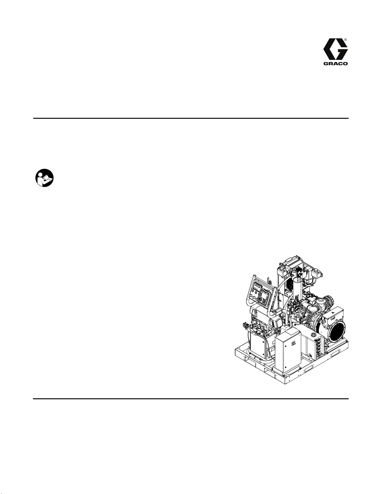
Reactor® 2 Elite Integrated
Proportioning System
Electric, Heated, Integrated Plural Component Proportioning System With Integrated Generator. For
spraying polyurethane foam and polyurea coatings. For professional use only. Not approved for use in
explosive atmospheres or hazardous locations. Not for outdoor use.
Important Safety Instructions. Read all warnings and instructions in
this manual. Save these instructions.
332636C
EN
PROVEN QUALITY. LEADING TECHNOLOGY.
Page 2

Contents
Warnings ........................................................... 3
Important Isocyanate Information......................... 8
Models............................................................... 10
Approvals........................................................... 12
Accessories........................................................ 12
Supplied Manuals............................................... 13
Related Manuals ................................................ 13
Typical Installation, without circulation.................. 14
Typical Installation, with circulation ...................... 15
Component Identification..................................... 16
Generator.................................................... 18
Proportioner Control Panel ........................... 19
Air Compressor............................................ 20
Advanced Display Module ............................ 21
Electrical Enclosure...................................... 26
Electrical Cabinet......................................... 27
Motor Control Module (MCM)........................ 28
Engine Control Module................................. 29
Load Center ................................................ 30
Temperature Control Module (TCM) Cable
Connections................................... 31
Circuit Breakers ........................................... 32
Overview............................................................ 34
Setup................................................................. 37
Locate Reactor ............................................ 37
Trailer Setup Guidelines............................... 38
Install Wall (optional).................................... 39
Connect Battery........................................... 41
Add Fuel ..................................................... 41
General Equipment Guidelines ..................... 42
Electrical Connections.................................. 42
Connect Feed Pumps................................... 42
Breathing Air................................................ 42
Connect Pressure Relief Lines...................... 43
Install Fluid Temperature Sensor .................. 43
Connect Heated Hose.................................. 43
Close gun fluid manifold valves A and
B ................................................... 44
Connect Whip Hose to Gun Or Gun Fluid
Manifold......................................... 44
Pressure Check Hose .................................. 44
Connect Remote Display Module .................. 44
Grounding ................................................... 45
Supply Wet Cups With Throat Seal Liquid
(TSL) ............................................. 46
Operation........................................................... 47
Initial System Setup ..................................... 47
Register and Activate the Graco Insite........... 48
Advanced Setup Screens ............................. 50
System 1..................................................... 51
System 2..................................................... 51
Recipes....................................................... 51
Run Mode ................................................... 53
Startup............................................................... 57
Fluid Circulation.................................................. 61
Circulation Through Reactor ......................... 61
Circulation Through Gun Manifold................. 62
Jog Mode .................................................... 62
Spraying ............................................................ 63
Spray Adjustments....................................... 64
Manual Hose Heat Mode.............................. 65
Shutdown........................................................... 67
Pressure Relief Procedure .................................. 69
Flushing............................................................. 70
System Errors ....................................................71
Troubleshoot Errors ..................................... 72
Clear Alarm ................................................. 72
Maintenance ...................................................... 73
Preventative Maintenance Schedule ............. 73
Wetcup........................................................ 73
Fluid Inlet Strainer Screen ............................ 73
Coolant Filter............................................... 73
Grease Circulation Valves ............................ 73
ISO Lubrication Level ................................... 73
Wiring Connections...................................... 73
Dust Protection ............................................ 73
Coolant Levels............................................. 73
Compressor Maintenance............................. 73
Clean Heat Sink Fins.................................... 74
Engine Maintenance .................................... 74
Air Compressor Oil Level.............................. 74
Fuel Tank.................................................... 75
Flush Inlet Strainer Screen ........................... 75
Pump Lubrication System............................. 76
USB Data........................................................... 77
USB Logs.................................................... 77
System Configuration Settings...................... 78
Download Log Files...................................... 79
Custom Language File ................................. 79
Upload Procedure........................................ 80
Appendix A: Engine Control Module..................... 81
Dimensions ........................................................ 84
Performance Charts............................................ 87
Technical Specifications...................................... 90
Graco Extended Warranty for Integrated
Reactor® 2 Components ....................... 93
2
332636C
Page 3

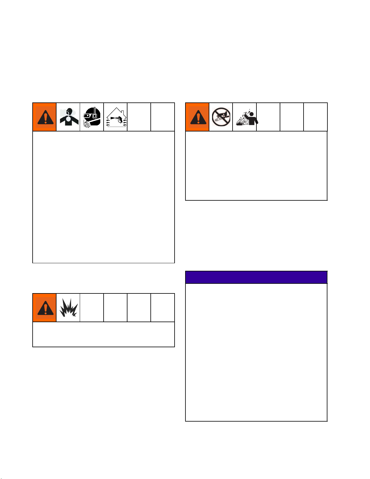
Warnings
Warnings
The following warnings are for the setup, use, grounding, maintenance, and repair of this equipment. The
exclamation point symbol alerts you to a general warning and the hazard symbols refer to procedure-specific
risks. When these symbols appear in the body of this manual or on warning labels, refer back to these
Warnings. Product-specific hazard symbols and warnings not covered in this section may appear throughout
the body of this manual where applicable.
WARNING
ELECTRIC SHOCK HAZARD
This equipment must be grounded. Improper grounding, setup, or usage of the system can
cause electric shock.
• Turn off and disconnect power at main switch before disconnecting any cables and before
servicing equipment.
• Connect only to grounded power source.
• All electrical wiring must be done by a qualified electrician and comply with all local codes
and regulations.
TOXIC FLUID OR FUMES
Toxic fluids or fumes can cause serious injury or death if splashed in the eyesoronskin,
inhaled, or swallowed.
• Read MSDSs to know the specific hazards of the fluids you are using.
• Store hazardous fluid in approved containers, and dispose of it according to applicable
guidelines.
• Always wear chemically impermeable gloves when spraying, dispensing, or cleaning
equipment.
CARBON MONOXIDE HAZARD
Exhaust contains poisonous carbon monoxide, which is colorless and odorless. Breathing
carbon monoxide can cause death.
• Donotoperateinanenclosedarea.
PERSONAL PROTECTIVE EQUIPMENT
Wear appropriate protective equipment when in the work area to help prevent serious injury,
including eye injury, hearing loss, inhalation of toxic fumes, and burns. This protective
equipment includes but is not limited to:
• Protective eyewear, and hearing protection.
• Respirators, protective clothing, and gloves as recommended by the fluid and solvent
manufacturer.
332636C 3
Page 4
Warnings
WARNING
SKIN INJECTION HAZARD
High-pressure fluid from gun, hose leaks, or ruptured components will pierce skin. This may
look like just a cut, but it is a serious injury that can result in amputation. Get immediate surgical
treatment.
• Do not spray without tip guard and trigger guard installed.
• Engage trigger lock when not spraying.
• Do not point gun at anyone or at any part of the body.
• Do not put your hand over the spray tip.
• Do not stop or deflect leaks with your hand, body, glove, or rag.
• Follow the Pressure Relief Procedure when you stop spraying and before cleaning, checking,
or servicing equipment.
• Tighten all fluid connections before operating the equipment.
• Check hoses and couplings daily. Replace worn or damaged parts immediately.
FIRE AND EXPLOSION HAZARD
Flammable fumes, such as solvent and paint fumes, in work area can ignite or explode. To help
prevent fire and explosion:
• Use equipment only in well ventilated area.
• Eliminate all ignition sources; such as pilot lights, cigarettes, portable electric lamps, and
plastic drop cloths (potential static arc).
• Keep work area free of debris, including solvent, rags and gasoline.
• Do not plug or unplug power cords, or turn power or light switches on or off when flammable
fumes are present.
• Ground all equipment in the work area. See Grounding instructions.
• Use only grounded hoses.
• Hold gun firmly to side of grounded pail when triggering into pail. Do not use pail liners unless
they are antistatic or conductive.
• Stop operation immediately if static sparking occurs or you feel a shock. Do not use
equipment until you identify and correct the problem.
• Keep a working fire extinguisher in the work area.
4
332636C
Page 5

Warnings
WARNING
THERMAL EXPANSION HAZARD
Fluids subjected to heat in confined spaces, including hoses, can create a rapid rise in pressure
due to the thermal expansion. Over-pressurization can result in equipment rupture and serious
injury.
• Openavalvetorelievethefluidexpansionduringheating.
• Replace hoses proactively at regular intervals based on your operating conditions.
PRESSURIZED ALUMINUM PARTS HAZARD
Use of fluids that are incompatible with aluminum in pressurized equipment can cause serious
chemical reaction and equipment rupture. Failure to follow this warning can result in death,
serious injury, or property damage.
• Do not use 1,1,1-trichloroethane, methylene chloride, other halogenated hydrocarbon
solvents or fluids containing such solvents.
• Many other fluids may contain chemicals that can react with aluminum. Contact your material
supplier for compatibility.
PLASTIC
Many solvents can degrade plastic parts and cause them to fail, which could cause serious
injury or property damage.
• Use only compatible water-based solvents to clean plastic structural or pressure-containing
parts.
•SeeTechnical Data in this and all other equipment instruction manuals. Read fluid and
solvent manufacturer’s MSDSs and recommendations.
PARTS CLEANING SOLVENT HAZARD
332636C 5
Page 6
Warnings
WARNING
EQUIPMENT MISUSE HAZARD
Misuse can cause death or serious injury.
• Do not operate the unit when fatigued or under the influence of drugs or alcohol.
• Do not exceed the maximum working pressure or temperature rating of the lowest rated
system component. See Technical Data in all equipment manuals.
• Use fluids and solvents that are compatible with equipment wetted parts. See Technical Data
in all equipment manuals. Read fluid and solvent manufacturer’s warnings. For complete
information about your material, request MSDS from distributor or retailer.
• Do not leave the work area while equipment is energized or under pressure.
• Turn off all equipment and follow the Pressure Relief Procedure when equipment is not in use.
• Check equipment daily. Repair or replace worn or damaged parts immediately with genuine
manufacturer’s replacement parts only.
• Do not alter or modify equipment. Alterations or modifications may void agency approvals
and create safety hazards.
• Make sure all equipment is rated and approved for the environment in which youareusingit.
• Use equipment only for its intended purpose. Call your distributor for information.
• Route hoses and cables away from traffic areas, sharp edges, moving parts, and hot surfaces.
• Do not kink or over bend hoses or use hoses to pull equipment.
• Keep children and animals away from work area.
• Comply with all applicable safety regulations.
BATTERY HAZARD
The battery may leak, explode, cause burns, or cause an explosion if mishandled.
• Only use the battery type specified for use with the equipment. See Technical Data.
• Battery maintenance must only be performed or supervised by personnel knowledgeable of
batteries and the required precautions. Keep unauthorized personnel away from battery.
• When replacing the battery, use the same lead-acid automotive battery, with 800 CCA
minimum, specified for use with the equipment. See Technical Data.
• Do not dispose of battery in fire. The battery is capable of exploding.
• Follow local ordinances and/or regulations for disposal.
• Do not open or mutilate the battery. Released electrolyte has been known tobeharmfulto
the skin and eyes and to be toxic.
• Remove watches, rings, or other metal objects.
• Only use tools with insulated handles. Do not lay tools or metal parts on top of battery.
MOVING PARTS HAZARD
Moving parts can pinch, cut or amputate fingers and other body parts.
• Keep clear of moving parts.
• Do not operate equipment with protective guards or covers removed.
• Pressurized equipment can start without warning. Before checking, moving, or servicing
equipment, follow the Pressure Relief Procedure and disconnect all power sources.
6 332636C
Page 7
Warnings
WARNING
ENTAGLEMENT HAZARD
Rotating parts can cause serious injury.
• Keep clear of moving parts.
• Do not operate equipment with protective guards or covers removed.
• Do not wear loose clothing, jewelry or long hair while operating equipment.
• Equipment can start without warning. Before checking, moving, or servicing equipment,
follow the Pressure Relief Procedure and disconnect all power sources.
BURN HAZARD
Equipment surfaces and fluid that is heated can become very hot during operation. To avoid
severe burns:
• Do not touch hot fluid or equipment.
CALIFORNIA PROPOSITION 65
The engine exhaust from this product contains a chemical known to the State of California to
cause cancer, birth defects or other reproductive harm.
332636C
7
Page 8
Important Isocyanate Information
Important Isocyanate Information
Isocyanates (ISO) are catalysts used in two component materials.
Isocyanate Conditions
Spraying or dispensing materials containing
isocyanates creates potentially harmful mists,
vapors, and atomized particulates.
Read material manufacturer’s warnings and
material MSDS to know specific hazards and
precautions related to isocyanates.
Prevent inhalation of isocyanate mists, vapors,
and atomized particulates by providing sufficient
ventilation in the work area. If sufficient ventilation
is not available, a supplied-air respirator is required
for everyone in the work area.
To prevent contact with isocyanates, appropriate
personal protective equipment, including
chemically impermeable gloves, boots, aprons,
and goggles, is also required for everyone in the
work area.
Keep Components A and B Separate
Cross-contamination can result in cured
material in fluid lines which could cause serious
injury or damage equipment. To prevent
cross-contamination:
• Never interchange component A and component
B wetted parts.
• Never use solvent on one side if it has been
contaminated from the other side.
Moisture Sensitivity of Isocyanates
Exposure to moisture (such as humidity) will cause
ISO to partially cure; forming small, hard, abrasive
crystals, which become suspended in the fluid.
Eventually a film will form on the surface and the ISO
will begin to gel, increasing in viscosity
Material Self-Ignition
Some materials may become self-igniting if applied
too thick. Read material manufacturer’s warnings
and material MSDS.
NOTICE
Partially cured ISO will reduce performance and
the life of all wetted parts.
• Always use a sealed container with a desiccant
dryer in the vent, or a nitrogen atmosphere.
Never store ISO in an open container.
• Keep the ISO pump wet cup or reservoir (if
installed) filled with appropriate lubricant. The
lubricant creates a barrier between the ISO and
the atmosphere.
• Use only moisture-proof hoses compatible with
ISO.
• Never use reclaimed solvents, which may
contain moisture. Always keep solvent
containers closed when not in use.
• Always lubricate threaded parts with an
appropriate lubricant when reassembling.
8 332636C
Page 9

Important Isocyanate Information
Foam Resins with 245 fa Blowing Agents
Some foam blowing agents will froth at temperatures
above 90°F (33°C) when not under pressure,
especially if agitated. To reduce frothing, minimize
preheating in a circulation system.
Changing Materials
NOTICE
Changing the material types used in your
equipment requires special attention to avoid
equipment damage and downtime.
• When changing materials, flush the equipment
multiple times to ensure it is thoroughly clean.
• Always clean the fluid inlet strainers after
flushing.
• Check with your material manufacturer for
chemical compatibility.
• When changing between epoxies and urethanes
or polyureas, disassemble and clean all fluid
components and change hoses. Epoxies often
have amines on the B (hardener) side. Polyureas
often have amines on the B (resin) side.
332636C 9
Page 10

Models
Models
Reactor 2 E-30i
All base systems include fluid inlet pressure and temperature sensors and Graco InSite™. For part numbers,
see Accessories, page 12.
Model
Base Machine 272079 272080 272089 272090
Maximum Fluid
Working Pressure
psi (MPa, bar)
Approximate Output
per Cycle (A+B) gal.
(liter)
Max Flow Rate lb/min
(kg/min)
Total System Load †
(Watts)
Voltage (phase) 240 VAC (1) 240 VAC (1) 240 VAC (1) 240 VAC (1)
Available Auxiliary
Current at Volts, 60
Hz*
E-30i E-30i with heat E-30i E-30i with heat
2000 (13.8, 138) 2000 (13.8, 138) 2000 (13.8, 138) 2000 (13.8, 138)
0.0272 (0.1034) 0.0272 (0.1034) 0.0272 (0.1034) 0.0272 (0.1034)
30 (13.5) 30 (13.5) 30 (13.5) 30 (13.5)
7,400 11,600 13,500 17,700
52 Amps (240) 35 Amps (240) 22 Amps (240)
No Air Compressor/Dryer With Air Compressor/Dryer
5 Amps (240)
9 Amps (120)
9 Amps (120)
Fusion AP Package
(Gun Part No.)
Fusion CS Package
(Gun Part No.)
Probler P2 Package
(Gun Part No.)
Heated Hose
50 ft (15 m)
Heated Whip Hose
10 ft (3 m)
Total system watts used by system, based on
maximum heated hose length of 310 ft (94.5 m)
for each unit.
* Full load amps available for auxiliary equipment
when all bare-system components are operating
at maximum capabilities. Available auxiliary
current is based on 310 ft (94.5 m) of heated hose.
An additional 3.0 amps (240 VAC) of auxiliary
current is available for each 50 ft (15.2 m) section
of heated hose that is not used.
liary current at 120 VAC is available on CB08,
Auxi
e 1 (circuit breaker pin 2), line 2 current at 120
lin
is used by the air dryer (circuit breaker pin 4).
VAC
AP2079
(246102)
CS2079
(CS02RD)
P22079
(GCP2R2)
24Y240 24Y240 24Y240 24Y240
246055 246055 246055 246055
AP2080
(246102)
CS2080
(CS02RD)
P22080
(GCP2R2)
AP2089
(246102)
CS2089
(CS02RD)
P22089
(GCP2R2)
Available auxiliary current will be less when the
engine is de-rated for site altitude. Reduce the
Available Auxiliary Current in the chart by 2.5
Amps (240 VAC) per 1000 ft (300 m) elevation
increments. If the available auxiliary current is
less than zero, the system configuration may not
support the full load at that altitude.
Includes Complete Air Compressor/Dryer Kit
24U176.
Refer to Circuit Breaker Configuration Options,
page 33.
See Approvals, page 12.
Packages include gun, heated hose, and whip
hose.
AP2090
(246102)
CS2090
(CS02RD)
P22090
(GCP2R2)
10 332636C
Page 11

Models
Reactor 2 E-XP2i
All base systems include fluid inlet pressure and temperature sensors and Graco InSite™. For part numbers,
see Accessories, page 12.
Model
Base Machine 272081 272091
Maximum Fluid Working Pressure psi
(MPa, bar)
Approximate Output per Cycle (A+B)
gal. (liter)
Max Flow Rate gal/min (l/min) 2.0 (7.6) 2.0 (7.6)
Total System Load † (Watts)
Voltage (phase) 240 VAC (1) 240 VAC (1)
Available Auxiliary Current at Volts, 60
Hz*
No Air Compressor/Dryer With Air Compressor/Dryer
E-XP2i with heat E-XP2i with heat
3500 (24.1, 241) 3500 (24.1, 241)
0.0203 (0.0771) 0.0203 (0.0771)
11,600 17,700
35 Amps (240) 5 Amps (240)
9 Amps (120)
Fusion AP Package
(Gun Part No.)
Probler
(Gun Par
Heated H
50 ft (15
Heated
10 ft (3
P2 Package
tNo.)
ose
m)
Whip Hose
m)
Total sy
maximum
for each
* Full load amps available for auxiliary equipment
when all bare-system components are operating
at maximum capabilities. Available auxiliary
current is based on 310 ft (94.5 m) of heated hose.
An additional 3.0 amps (240 VAC) of auxiliary
current is available for each 50 ft (15.2 m) section
of heated hose that is not used.
Auxiliary current at 120 VAC is available on line 1
(circuit breaker pin 2), line 2 current at 120 VAC is
used by the air dryer (circuit breaker pin 4).
stem watts used by system, based on
heated hose length of 310 ft (94.5 m)
unit.
AP2081
(246101)
P22081
(GCP2R1)
24Y241 24Y241
246055 246055
AP2091
(246101)
P22091
(GCP2R1)
ble auxiliary current will be less when the
Availa
is de-rated for site altitude. Reduce the
engine
ble Auxiliary Current in the chart by 2.5
Availa
Amps (2
increm
less th
suppor
Includes Complete Air Compressor/Dryer Kit
24U176.
Refer to Circuit Breaker Configuration Options,
page 33.
See Approvals, page 12.
Packages include gun, heated hose, and whip
hose.
40 VAC) per 1000 ft (300 m) elevation
ents. If the available auxiliary current is
an zero, the system configuration may not
t the full load at that altitude.
332636C
11
Page 12
Approvals
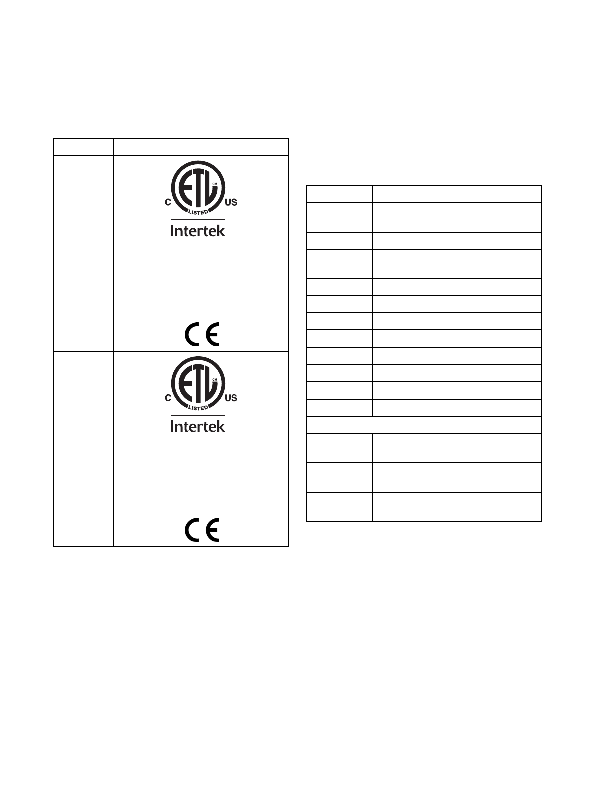
Approvals
Intertek approvals apply to proportioning systems
without hoses.
Model
272079
272089
272080
272081
272090
272091
Proportioning System Approvals:
9902471
Conforms to ANSI/UL Std. 73
Certified to CAN/CSA Std.
C22.2 No. 68
Note
Heated hoses provided with a system or sold
individually are not approved by Intertek.
Accessories
Kit Number Description
15M483 Remote Display Module Protective
Covers (10 pack)
15V551
24K207
24K333
24K336 Hose Rack
24K337 Light Tower Kit
24L911
24M174
24U174 Remote Display Module Kit
24U176
24U177
ADM Protective Covers (10 pack)
Fluid Temperature Sensor (FTS)
with RTD
Fuel Line and Cable Extension Kit
Pallet Support Kit
Drum Level Sticks
CompleteAirCompressorKit
Feed Pump Shutdown Kit
9902471
rms to ANSI/UL Std. 499
Confo
fiedtoCAN/CSAStd.
Certi
C22.2
No. 88
Cables
121006
24N365 RTD Test Cables (to aide resistance
24N449
150 ft (45 m) cable (for remote
display module)
measurements)
50 ft (15 m) CAN cable (for remote
display module)
12
332636C
Page 13
Supplied M anuals
Supplied Manuals
The following manuals are shipped with the Reactor.
Refer to these manuals for detailed equipment
information.
Manuals are also available at www.graco.com.
Manual Description
332637 Reactor 2 Elite Integrated
Proportioning System, Repair-Parts
333093 Reactor 2 Elite Integrated
Proportioning System, Startup
Instructions
333094 Reactor 2 Elite Integrated
Proportioning System, Shutdown
Instructions
SEBU8311–02Perkins® Engine, Repair-Parts
Access at www.perkins.com. Go
to Service and Support/manuals.
Select engine family and type code
“GN”.
-
ST
15825–00
33227482
Mecc Alte Self-Regulating Alternator
Series NPE, Repair-Parts
Access at www.meccalte.com.
Select “meccalte” logo / Download
/ Instruction Manuals. Select NPE
instruction manual on page 5. Go to
Support and enter serial number for
Parts List and Help Videos.
Contact Mecc Alte for warranty and
service
Air Compressor, Operation/Maintenance & Parts list.
Access at www.hydrovaneproducts.com. Go to Warranty & Service
tab and select “contact us” to
request manuals.
Refrigerated Air Dryer, Instruction
manual
Access from Service
Department (724) 746–1100 or
www.spx.com/en/hankison.
Related Manuals
The following manuals are for accessories used with
the Reactor.
Component Manuals in English:
Manuals are available at www.graco.com.
System Manuals
332737 Reactor 2 E-30i and E-XP2i,
Repair-Parts
Displacement Pump Manual
309577 Electric Reactor Displacement Pump,
Repair-Parts
Feed System Manuals
309572 Heated Hose, Instructions-Parts
309852
309815 Feed Pump Kits, Instructions-Parts
309827
Spray Gun Manuals
309550 Fusion ™ AP Gun
312666 Fusion ™ CS Gun
313213 Probler P2 Gun
Accessory Manuals
332733 Air Compressor and Air Dryer Kit,
3A1905
3A1906 Light Tower Kit, Instructions-Parts
3A1904 Fuel Tank/Battery Move Kit,
3A1903 Hose Rack, Instructions-Parts
332738
3A1907 Remote Display Module,
3A2574
Circulation and Return Tube Kit,
Instructions-Parts
Feed Pump Air Supply Kit,
Instructions-Parts
Instructions-Parts
Feed Pump Shutdown Kit,
Instructions-Parts
Instructions-Parts
Booster Heat Retrofit Kit,
Instructions-Parts
Instructions-Parts
Pallet Support Kit, Instructions-Parts
332636C 13
Page 14
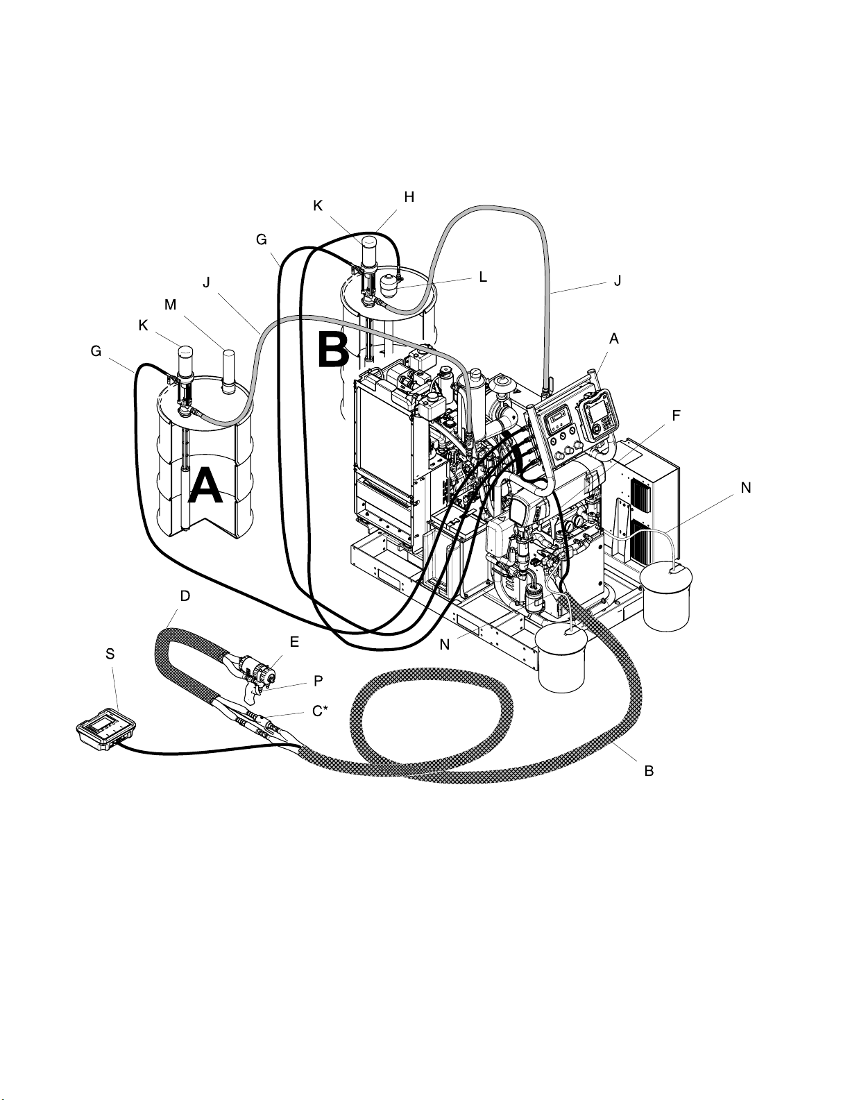
Typical Installation, without circulation
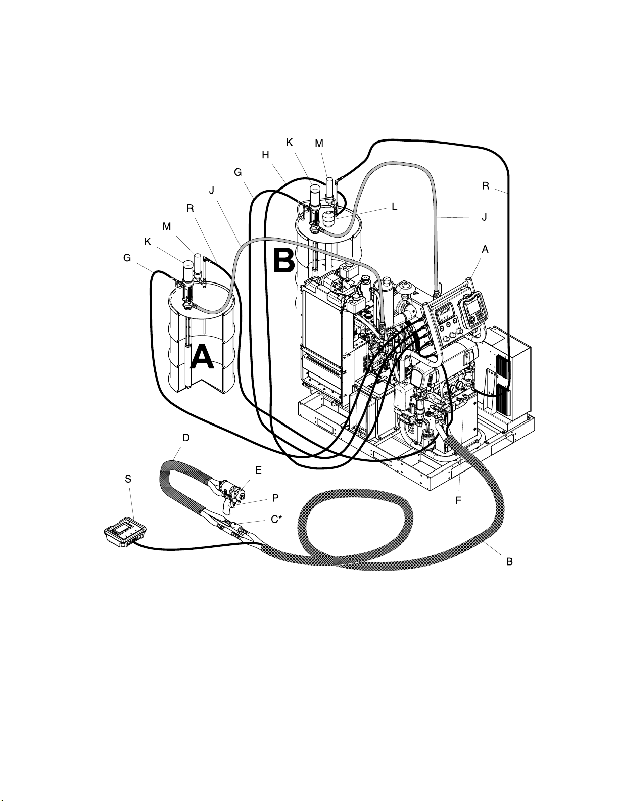
Typical Installation,
without circulation
Figure 1
* Shown exposed for clarity. Wrap with tape during operation.
A Reactor Proportioner
BHeatedHose
C Fluid Temperature Sensor (FTS)
D Heated Whip Hose
E
F
G Feed Pump Air Supply Lines
H
14
Fusion Spray Gun
Gun Air Supply Hose
Agitator Air Supply Line
J
K Feed Pumps
L Agitator
M Desiccant Dryer
N Bleed Lines
P
S Remote Display Module Kit (optional)
Fluid Supply Lines
Gun Fluid Manifold (part of gun)
332636C
Page 15
Typical Installation, with circulation
Typical Installation, with circulation
Figure 2
* Shown exposed for clarity. Wrap with tape during operation.
A Reactor Proportioner
BHeatedHose
C Fluid Temperature Sensor (FTS)
D HeatedWhipHose
E
F
G Feed Pump Air Supply Lines
H
332636C 15
Fusion Spray Gun
Gun Air Supply Hose
Agitator Air Supply Line
J
K Feed Pumps
L Agitator
MDesiccantDryer
P
R Recirculation Lines
S Remote Display Module (optional)
Fluid Supply Lines
Gun Fluid Manifold (part of gun)
Page 16
Component Identification
Component Identification
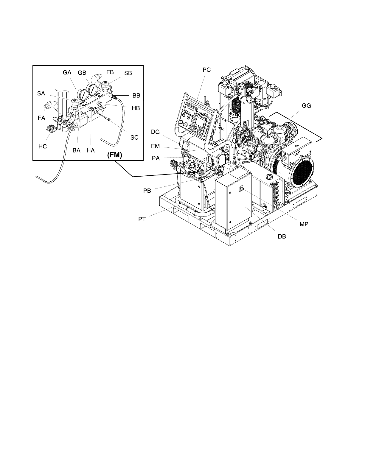
Figure
3 Front View
BA
BB
DG Drive Gear Housing
DB Electrical Enclosure
EM Electric Motor
FA
FB
FM
GA Component A Pressure Gauge
GB Component B Pressure Gauge
GG Generator, page 18
HA
HB
Component A Pressure Relief Outlet
Compon
Component A Fluid Manifold Inlet
Component B Fluid Manifold Inlet
Reactor Fluid Manifold
Component A Hose Connection
Component B Hose Connection
ent B Pressure Relief Outlet
HC Heated Hose Electrical Connectors
MP
PA
PB
PC Prop
PT Pallet
SA Comp
SB Component B PRESSURE
SC Fl
TA
TB Component B Pressure Transducer
Main Power Switch
Component A Pump
Component B Pump (behind Electrical
Enclosure)
ortioner Control Panel, page 19
onent A PRESSURE
EF/SPRAY Valve
RELI
RELIEF/SPRAY Valve
uid Temperature Sensor (FTS) Cable
mponent A Pressure Transducer
Co
ehind gauge GA)
(b
(behind gauge GB)
16 332636C
Page 17
Component Identification
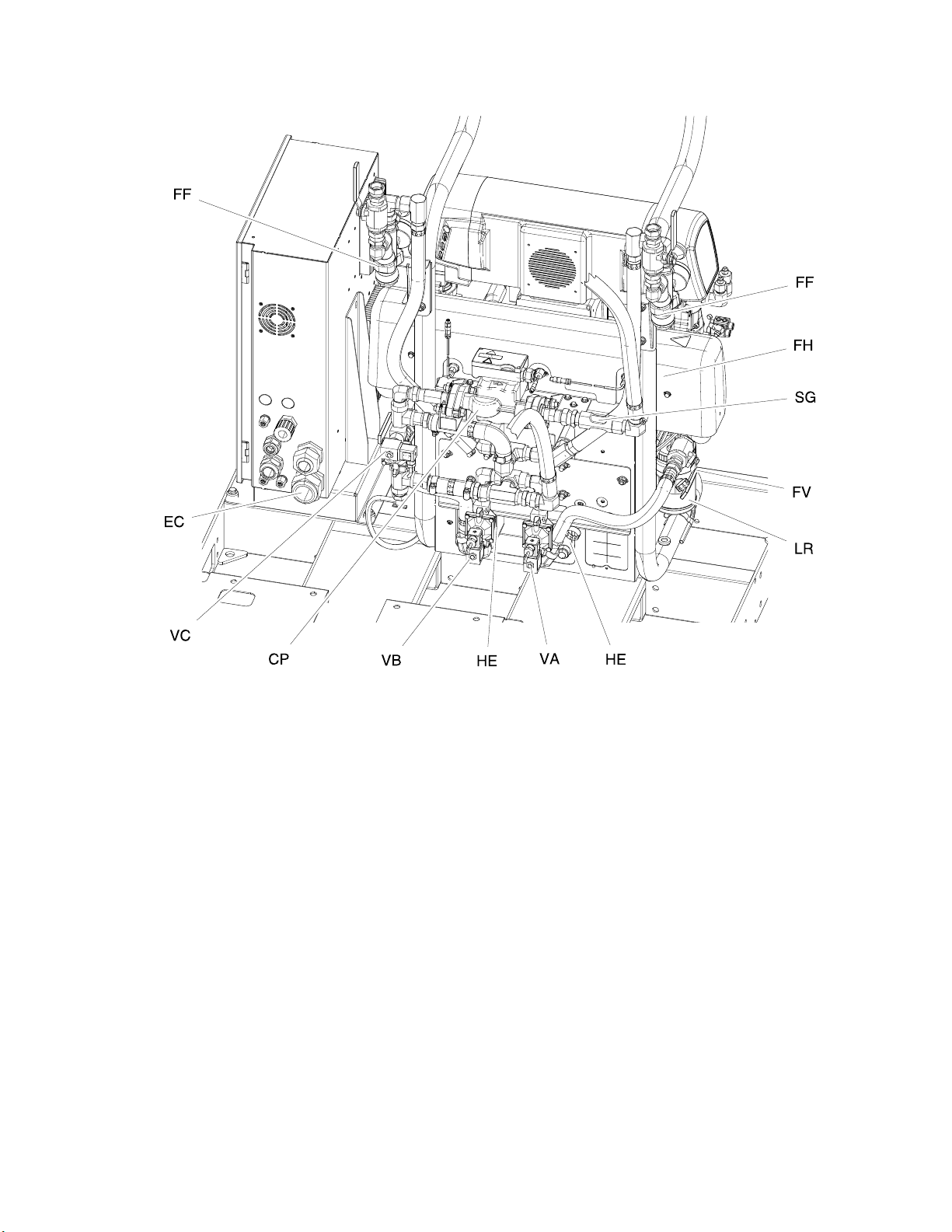
Figure 4 Back View
CP Circulation Pump
EC Electrical Cord Strain Relief
FF
FH
FV
HE
Y-strainer (includes pressure
gauge, temperature gauge, and
pressure/temperature sensor)
Booster Fluid Heater (not included with all
models)
Fluid Inlet Valve (A side shown)
Heat Exchangers (heat exchanger coolant
loop)
HM
LR ISO Pump Lubricant Reservoir
MM Motor Control Module (MCM), page 28
SG Sight Glass
VA Component A Control Valve
VB Component B Control Valve
VC Bypass Control Valve
Temperature Control Module (TCM) Cable
Connections, page 31
332636C
17
Page 18
Component Identification
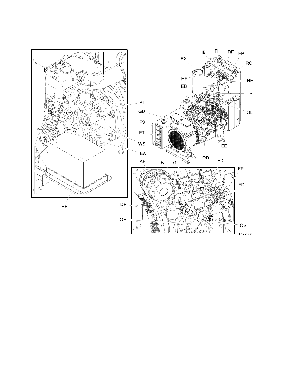
Generator
Figure 5
AF Air Filter
BE
DF Diesel Fuel Filter
EA
EB
EE Engine
ED
ER Radiator
EX Exhaust
FD
FH Filter Housing
FJ Fuel Injector
FP Fuel Pump
FS Diesel Fuel Fill Cap
Battery (not supplied)
12V Charge Alternator
Engine Coolant Expansion Bottle
Engine Oil Dipstick
Fuel Shutoff Solenoid
FT Diesel Fuel Tank
GD Gen
GL Glo
HB
HE Heat Exchanger
HF
OD Oi
OF Oi
L
O
S
O
C
R
RF Radiator Fan
T
S
TR Coolant Temperature Sensor
WS Over-Temperature Switch
erator Power Distribution Box
wPlugs
t Exchanger Coolant Expansion Bottle
Hea
at Exchanger Coolant Fill Bottle
He
lDrain
lFilter
il Fill
O
il Pressure Switch
O
ngine Coolant Radiator Cap
E
tarter
S
18 332636C
Page 19
Component Identification
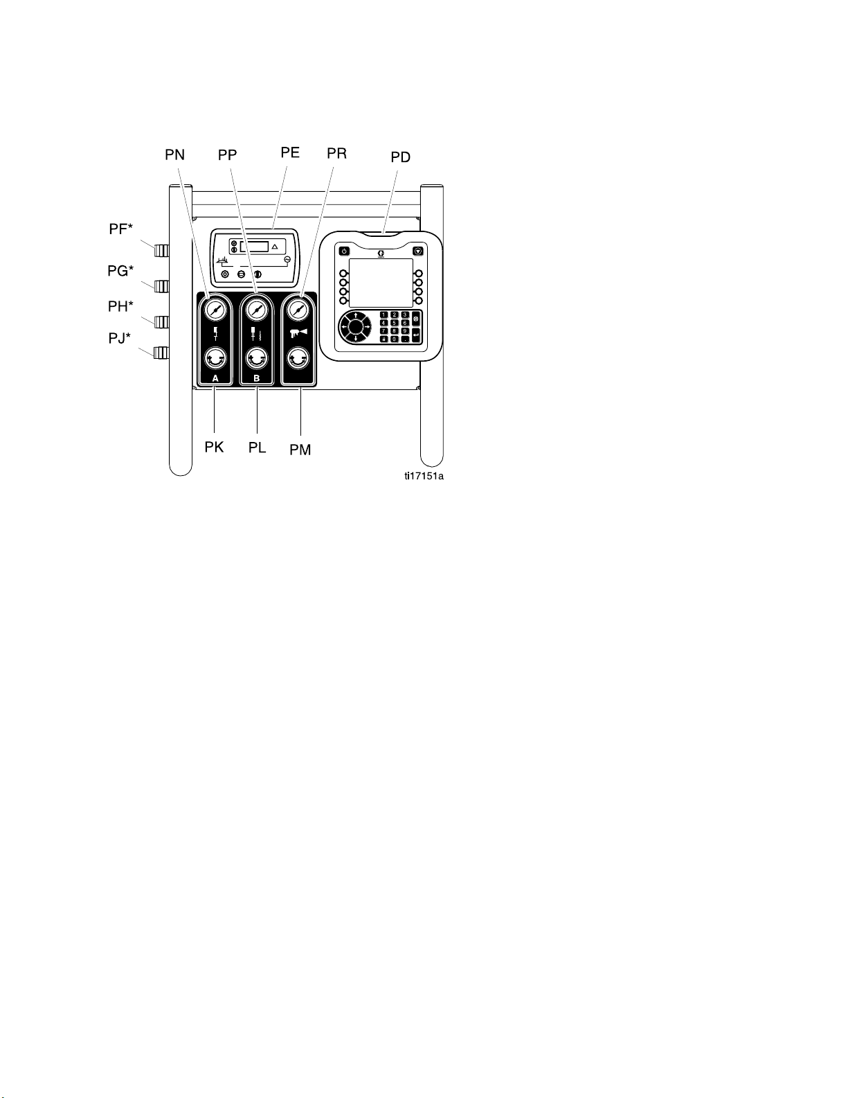
Proportioner Control Panel
Figure 6
PD
PE
PF* Component A Feed Pump Air Outlet
PG* Component B Feed Pump Air Outlet
PH* Agitator Air Outlet
PJ* Gun Air Outlet
PK
PL
PM Gun Air Regulator
PN Component A Feed Pump Pressure Gauge
PP Component B Feed Pump and Agitator
PR
* Not for breathing air use.
Advanced Display Module (ADM), page 21
Engine Control Module, page 29
Component A Feed Pump Air Regulator
Component B Feed Pump and Agitator Air
Regulator
Pressure Gauge
Gun Pressure Gauge
332636C 19
Page 20
Component Identification
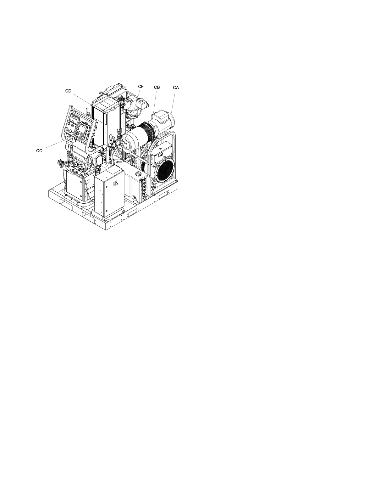
Air Compressor
Select models are supplied with an air compressor
and air dryer.
CA Air Compressor
CB
CC Air Compressor and Dryer On/Off Switch
CD Refrigerated Air Dryer
CE Air Dryer Drain Tube (bottom of refrigerated
CF Air Compressor Pressure Gauge
Power Box
air dryer; not shown)
Figure 7
20 332636C
Page 21
Component Identification
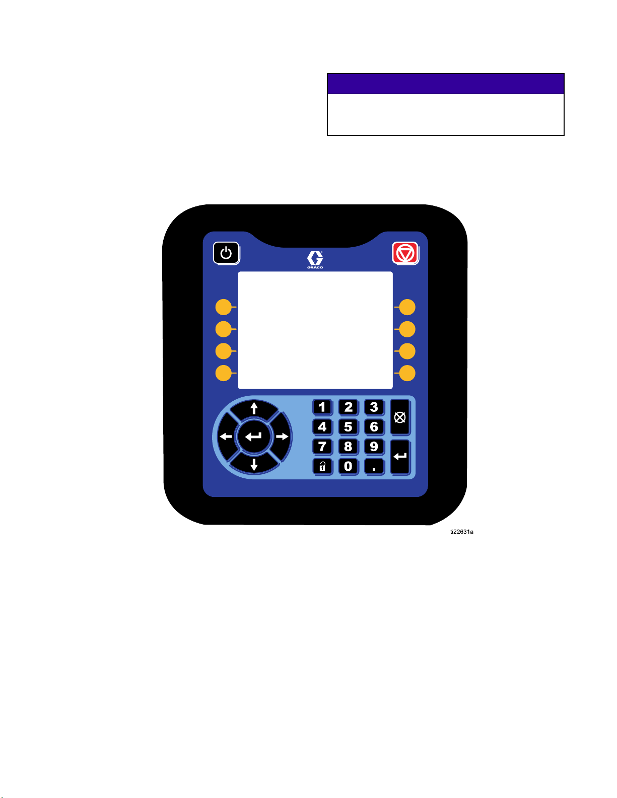
Advanced Display Module
The ADM display shows graphical and text
information related to setup and spray operations.
For detail on the display and individual screens, see
Run Mode, page 53,orSetup Mode.
Use the USB port on the ADM to download or upload
data. For more information about the USB data, see
USB Data, page 77.
NOTICE
To prevent damage to the softkey buttons, do not
press buttons with sharp objects such as pens,
plastic cards, or fingernails.
Figure 8 Front View
332636C
21
Page 22
Component Identification
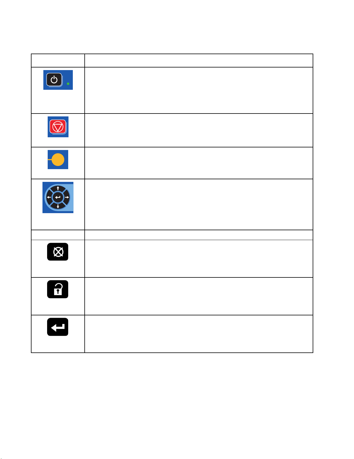
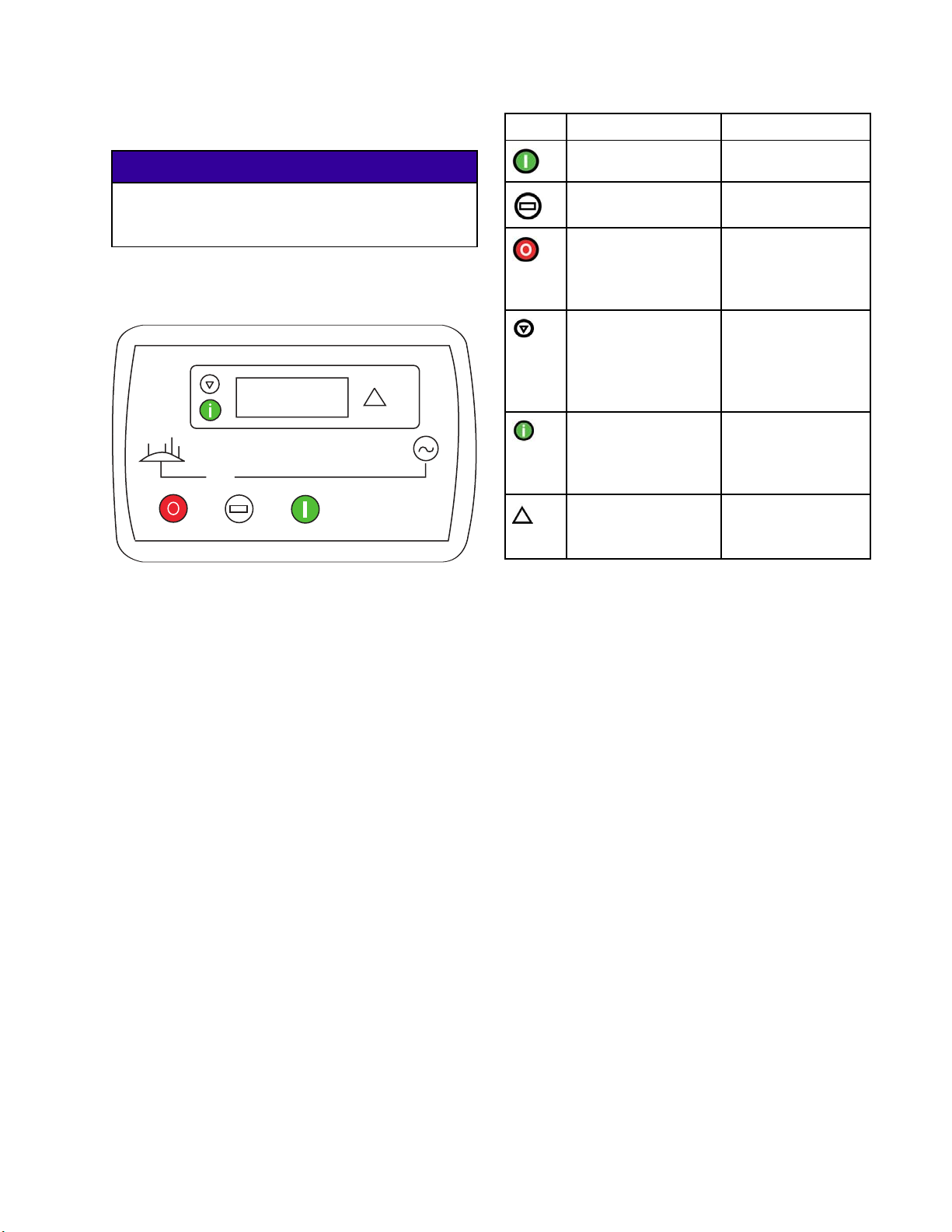
Table 1 : ADM Keys and Indicators
Key Function
Press to startup or shutdown the system.
Stop
tdown
ator
Press to stop all proportioner processes. This Is not a safety or emergency stop.
Press to select the specific screen or operation shown on the display directly next to
each key.
•
Left/Right Arrows:
•
Up/Down Arrows:
menu, or multiple screens within a function.
Use to cancel a data entry field.
Startup/Shu
Key and Indic
Soft Keys
Navigation Keys
Numeric Keypad Use to input values.
Usetomovefromscreentoscreen.
Use to move among fields on a screen, items on a dropdown
22
Cancel
Press to enter or exit Setup mode.
Setup
Press to choose a field to update, to make a selection, to save a selection or value, to
enter a screen, or to acknowledge an event.
Enter
332636C
Page 23
Component Identification
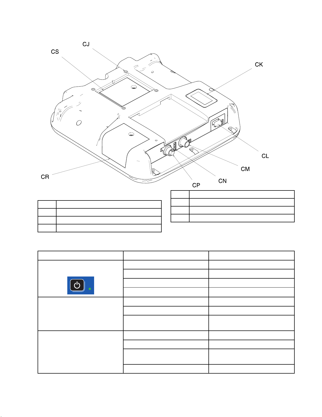
Figure 9 Back View
CJ Flat Panel Mount (VESA 100)
CK Model and Serial Number
CL USB Port and Status LEDs
CM CAN Cable Connection
Table 2 ADM LED Status Descriptions
LED
System Status
USB Status (CL)
ADM Status (CN)
CN Module Status LEDs
CP Accessory Cable Connection
CR Token Access Cover
CS Battery Access Cover
Conditions
Green Solid Run Mode, System On
Green Flashing Setup Mode, System On
Yellow Solid Run Mode, System Off
Yellow Flashing
Green Flashing
Yellow Solid Downloading information to USB
Green and Yellow Flashing ADM is busy, USB cannot transfer
Green Solid
Yellow Solid Active Communication
Description
Setup Mode, System Off
Data recording in progress
informationwheninthismode
Power applied to module
Red Steady Flashing Software upload from token in
progress
Red Random Flashing or Solid
Module error exists
332636C 23
Page 24
Component Identification
ADM Display Details
Power Up Screen
The following screen appears when the ADM is
powered up. It remains on while the ADM runs
through initialization and establishes communication
with other modules in the system.
Menu Bar
The menu bar appears at the top of each screen.
(The following image is only an example.)
System Mode
The current system mode is displayed at the lower
left of the menu bar.
Alarm/Deviation
The current system error is displayed in the middle of
the menu bar. There are four possibilities:
Icon Function
No Icon
Status
The current system status is displayed at the lower
right of the menu bar.
No information or no error has occurred
Advisory
Deviation
Alarm
Navigating the Screens
There are two sets of screens:
• The Run screens control spraying operations and
display system status and data.
Date and Time
The date and time are always displayed in one of
the following formats. The time is always displayed
as a 24-hour clock.
• DD/MM/YY HH:MM
• YY/MM/DD HH:MM
• MM/DD/YY HH:MM
Arrows
The left and right arrows indicate screen navigation.
Screen Menu
The screen menu indicates the currently active
screen, which is highlighted. It also indicates the
associated screens that are available by scrolling left
and right.
• The Setup screens control system parameters and
advanced features.
Press
screens. If the system has a password lock, the
Password screen displays. If the system is not locked
(password is set to 0000), System Screen 1 displays.
Press
Home screen.
Press the Enter soft key
function on any screen.
Press the Exit soft key
Use the other softkeys to select the function adjacent
to them.
on any Run screen to enter the Setup
onanySetupscreentoreturntothe
to activate the editing
to exit any screen.
24
332636C
Page 25
Icons
Screen Icons
Component Identification
Softkey Icons
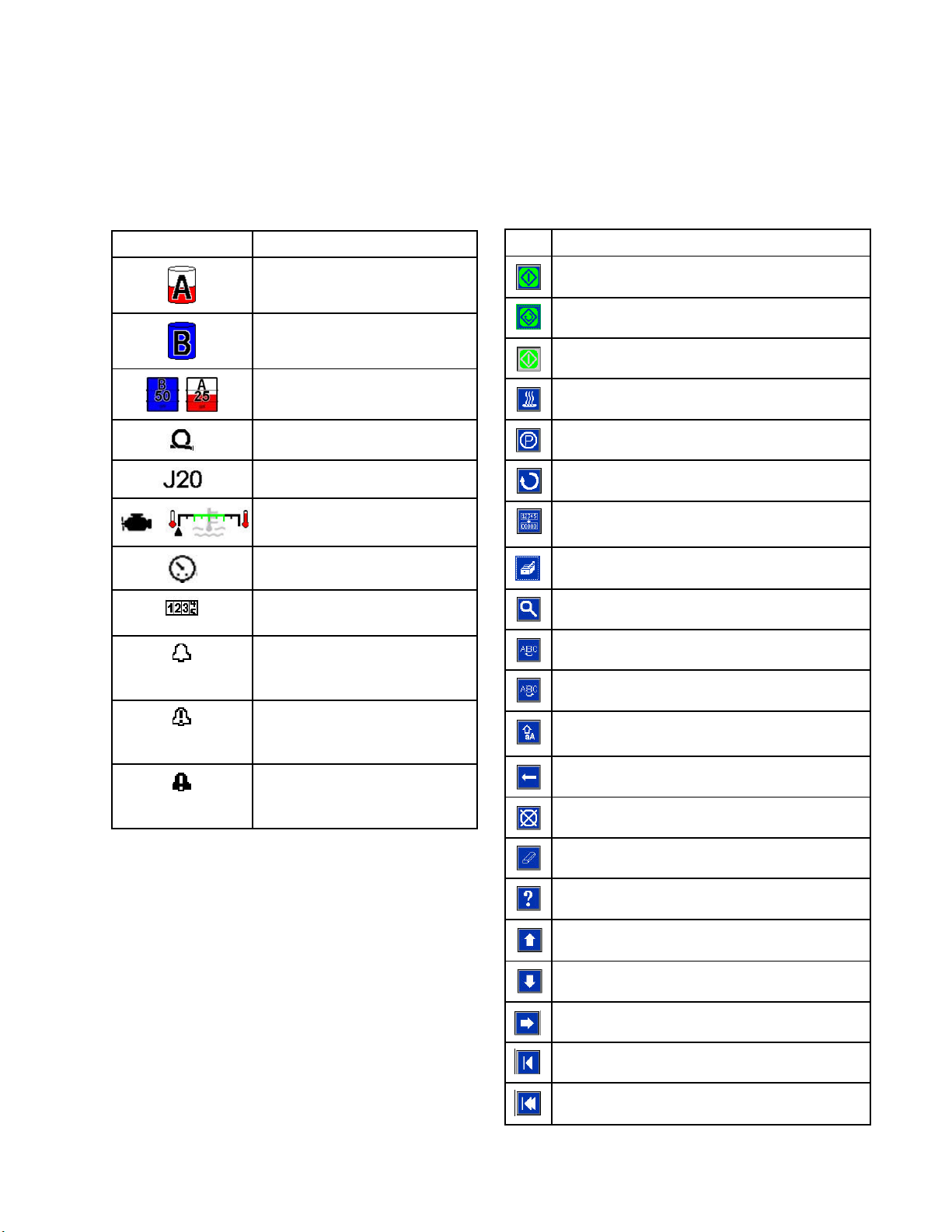
These are frequently used icons on the screens.
The following descriptions explain what each icon
represents.
Icon Description
Component A
Component B
Estimated Supply Material
Hose Temperature
Jog Mode Speed
Engine Coolant Temperature
Pressure
Cycle Counter (press and
hold)
Advisory. See
System Errors, page 71 for
more information.
The following icons appear in the ADM, directly to
the left or right of the soft key which activates that
operation.
Icon Function
Start Proportioner
Start and Stop Proportioner in Jog Mode
Stop Proportioner
Turn on specified heat zone.
Park component A pump
Enter Jog Mode. See Jog Mode, page 62
Cycle Counter
Reset
s and hold)
(pres
Select Recipe
Search
Move Cursor Left One Character
Move Cursor Right One Character
Deviation. See
System Errors, page 71 for
more information
Alarm. See
System Errors, page 71 for
more information
Toggle between upper-case, lower-case,
and numbers and special characters.
Backspace
ncel
Ca
Clear
Troubleshoot Selected Error
Increase value
Decrease value
Next screen
Previous screen
Return to first screen
332636C 25
Page 26
Component Identification
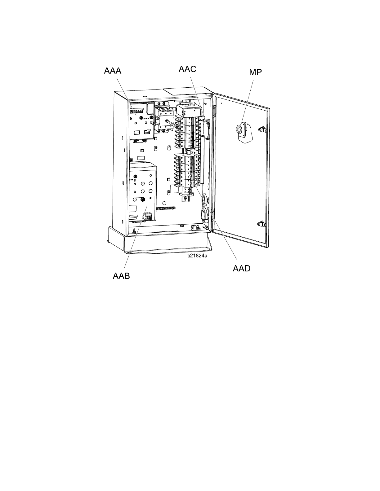
Electrical Enclosure
AAA Temperature Control Module (TCM)
AAB Motor Control Module (MCM)
AAC Enclosure Fan
AAD Circuit Breakers
MP Main Power Switch
26 332636C
Page 27
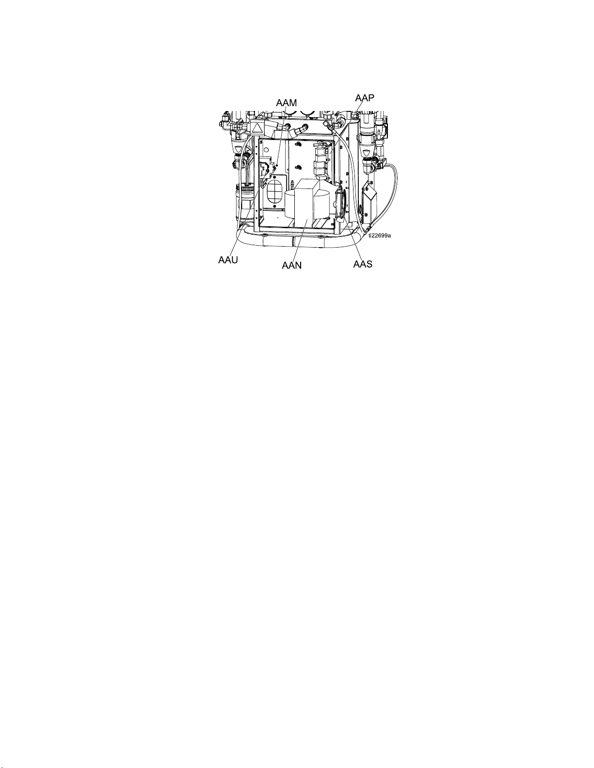
Electrical Cabinet
AAM Hose Breaker
AAN Transformer
AAP Load Center
Component Identification
AAS Fan
AAU Wiring Terminal Blocks
332636C
27
Page 28
Component Identification
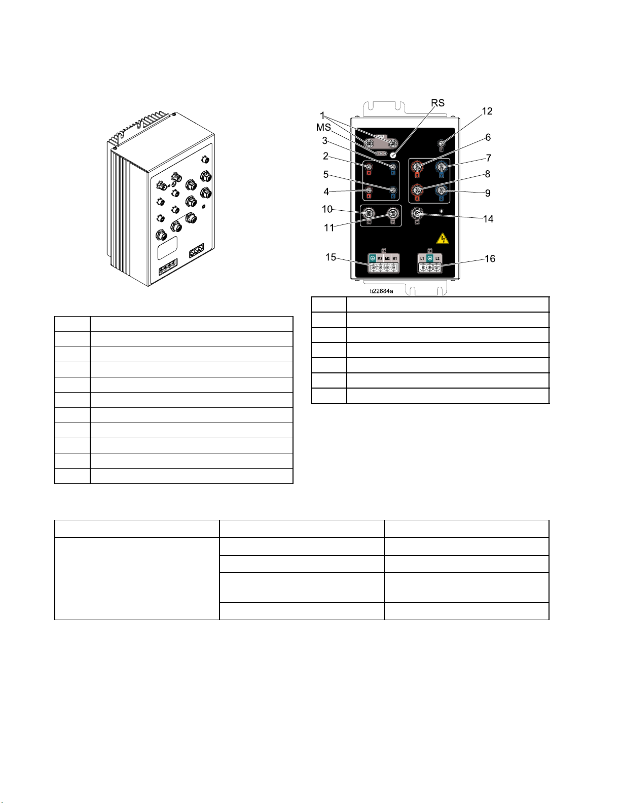
Motor Control Module (MCM)
Figure 10
Description
MB
1
2
3
4
5
6
7
8
9
Table 3 MCM Module LED (MB) Status Descriptions
LED
MCM Status
Module St
CAN Comm
Motor Temperature
Engine Coolant Temperature
Heat Exchanger A Temperature
Heat Exchanger B Temperature
A Pump Output Pressure
B Pump Output Pressure
A Fluid
BFlui
atus LEDs see LED Status Table
unication Connections
Inlet Sensor
d Inlet Sensor
Conditions
Green Solid
Yellow Solid Active Communication
Red Steady Flashing Software upload from token in
10
11 Load Center
12
13 Not Used
14 Graco Insite
15
16
MCM Rotary Switch Positions
0=E-30i
1=E-XP2i
Accessor
Pump Cyc
Motor Power Output
Main Pow
y Output
le Counter
™
er Input
Description
Power applied to module
progress
Red Random Flashing or Solid
Module error exists
28 332636C
Page 29
Component Identification
Engine Control Module
NOTICE
To prevent damage to the softkey buttons, do not
press buttons with sharp objects such as pens,
plastic cards, or fingernails.
For more information about the engine control module,
see Appendix A: Engine Control Module, page 81.
Icon Description Function
On Start Engine
Auto
Off Stop all system
Scroll Scroll through the
Page Select
Error Lamp Indicates error
Auto mode (not
used)
processes. Is
not a safety or
emergency stop.
instruments or
recorded events
on the currently
displayed page
Toggle between
the information
page and the error
log page
is present on
generator
Figure 11
332636C 29
Page 30

Component Identification
Load Center
F3 Radiator Fan Fuse
F4
K1 Fuel Relay
K2
K3
K4 Radiator Fan Relay
MV
Load Center Power Fuse
Starter Relay
Glow Plug Relay
Manual Valve Switch
LED
D1
D2
D3
D4
D10 A Coolant Valve Red
D12 B Coolant Valve Blue
D14
D23
Related
Component
Fuel Shutoff
Solenoid (FS)
Starter (ST)
Glow Plugs
(GL)
Radiator Fan
(RF)
Bypass Coolant
Valve
Manual Valve
Switch (MV)
Color
Green
Red
Green
Green
Green
Red
ON-State
Description
Fuel shutoff
solenoid on the
engine is open.
Starter is
cranking.
Glow plugs are
heating.
Radiator fan is
on.
A-side (red)
coolant valve is
open.
B-side (blue)
coolant valve is
open.
Bypass coolant
valve is open.
Manual valve
switch is in the
ON position.
30 332636C
Page 31

Temperature Control Module (TCM) Cable Connections
Component Identification
Figure 12
1 Power Input
2 Heater Overtemperature
3 CAN Communications Connections
4
5
6
Power Out (ISO)
Power Out (Res)
Power Out (Hose)
7
8
9
10 Hose T
Module Status LEDs (see
Advanced Display Module (ADM), page 21,
Boost Heater A Temperature (ISO)
(CN) for conditions
Boost Heater B Temperature (RES)
emperature
332636C 31
Page 32

Component Identification
Circuit Breakers
CM 24N750
T
24R754
MCM 24N953
P100 - Green/Y
P010 - Black
P020 - Red
P030 - Black
P040 - Red
P050 - Black
P060 - Red
P070 - Black
P090 - Green/Y
P080 - Red
ellow
ellow
ess
rn
a
r H
e
k
ea
Br
w
o
l
l
e
/Y
n
ee
r
G
090
P
w
o
ll
e
/Y
n
ee
r
G
00
P1
Disconnect
CT01
k
ac
- Bl
00
K1
w
o
ll
e
/Y
n
ee
r
G
0
P11
ed
- R
0
K11
P110 - Green/Y
k
wn
o
lac
lue
B
Br
B
ellow
FAN
Red
Black
PS1
1
NEUTRAL
0
B
C
2
0
B
C
03
il
B
a
C
4
0
B
C
r DIN R
e
k
B11T
T
ea
2
1
Br
B
05
B
C
6
0
B
C
7
0
B
C
08
B
C
A
P010 - Black
P020 - Red
te
- Whi
0
K12
P030 - Black
P040 - Red
P050 - Black
P060 - Red
P070 - Black
P080 - Red
5
A
5
1
A
5
1
A
30
A
0
2
A2
40
A
0
15 A
Blulkhead Connector
Figure 13 Circuit Breaker Connections Inside
Electrical Enclosure (DB)
Note
Not all wires are shown.
Ground Bar
Ref. Size Component
CB01
CB02
CB03
CB04
CB05
Ground T
erminal
5A
Power Supply, Fan,
Coolant Pump
15 A Boost Heat A
15 A Boost Heat B
30 A Hose Heat
20 A
Motor Control
CB06* 40 A Air Compressor/Open
CB07*
CB08*
20 A
15 A
Open
Air Dryer/Open
* Contact Graco for circuit breaker options.
32 332636C
Page 33

Component Identification
Circuit Breaker Configuration Options
Improper configuration can result in electric shock.
All electrical wiring must be done by a qualified
electrician and comply with all local codes and
regulations. See page 27 and 28 for correct circuit
breaker configuration.
Figure 14 Circuit Breakers Inside Proportioner
Cabinet
Ref. Size Component
CB20
Figure 15 Circuit Breakers Inside Alternator
Assembly
Ref. Size Component
CB10 90 A 120/240V Alternator
50 A Heated Hose
See Circuit Breakers, page 32 for recommended
circuit breaker configuration.
Sub-Panel Options
Some customer changes are acceptable to
accommodate larger loads from auxiliary equipment
or a sub-panel. It is suggested that circuit breakers
CB07 be substituted to accommodate larger loads
or a sub-panel. The total auxiliary equipment
loads added to the configuration must be limited
to the system’s available auxiliary current. See
Models, page 10, for available auxiliary current at
240V, 60Hz.
See the Reactor repair manual for optional circuit
breakers and their current ratings. Circuit breakers
used must meet UL489 specifications.
Auxiliary Wiring Diagram Options.
The generator supplies power in a 3-wire,
single-phase, mid-point neutral wiring configuration.
For 240 VAC loads, wire the load across the output
terminals of the circuit breaker. For 120 VAC loads,
wire the load between the neutral terminal blocks
below the circuit breaker to one pole of the circuit
breaker. See electrical diagrams in Reactor repair
manual.
Disable Booster Heat
Disable booster heat to allow use of power for
additional auxiliary power.
To replace or repair a circuit breaker, see the Reactor
2 Integrated Repair manual.
332636C 33
Page 34

Overview
Overview
The system uses two coolant loops to use heat
released from the engine to heat the A and B
component material to the target temperatures
defined on the ADM (PD).
The engine coolant loop (gray) circulates heated
coolant from the engine (EE), through the heat
exchanger (HE), radiator (ER), and back to the
engine. Coolant in the proportioner coolant loop
(black) captures heat from the engine coolant loop
inside the heat exchanger (HE) near the radiator.
Figure 16 Engine Coolant Loop and Proportioner
Coolant Loop
34 332636C
Page 35

Overview
The proportioner coolant loop circulates coolant
through secondary heat exchangers (HE) located
on the back of the proportioner to heat the A
and B component material before the material is
pressurized in the proportioner pumps (PA, PB). After
the A and B material has been heated in the heat
exchangers, the material enters the fluid manifold
(FM) and heated hose.
For models with a booster heater, the A and B
material enters the booster heater after the material
is pressurized in the proportioning pumps to heat the
material higher than 140°F (60°C).
Figure 17 A and B Component Material Flow
332636C 35
Page 36

Overview
Coolant only flows through the secondary heat
exchangers when the heat exchanger control valves
(VA, VB) are open and the A and B component
temperatures are below the target temperatures set
on the ADM. See Fig 18.
When the control valves (VA, VB) close, the A
and B material has reached target temperature.
Coolant flows through the bypass control valve (VC),
circulation pump (CP), sight glass (SG), proportioner
coolant fill bottle (HF), and back to the heat exchanger
in the engine coolant loop. See Fig. 19.
Figure 1
Valves O
8 Proportioner Coolant Loop — A and B
pen (heating material)
Figure 19 Proportioner Coolant Loop — A and B
Valves Closed (not heating material)
36 332636C
Page 37

Setup
Setup
NOTICE
Proper system setup, startup, and shutdown
procedures are critical to electrical equipment
reliability. The following procedures ensure steady
voltage. Failure to follow these procedures will
cause voltage fluctuations that can damage
electrical equipment and void the warranty.
Do not remove or separate the proportioner, engine
assembly, or power distribution box from the pallet.
Failure to leave the component mounting intact will
cause heating efficiency degradation, and potential
unsafe wiring and grounding.
Locate Reactor
1. Install hose rack, if ordered. See manual 3A1903
for detailed instructions.
2. Locate Reactor on a level surface that is
nonporous and diesel resistant, such as diamond
plate.
3. Do not expose Reactor to rain or below 20°F
(-7°C).
NOTICE
To ensure the heat exchanger control valves
open and close properly, do not store Reactor
below 20°F (-7°C).
4. If a wall will be installed between the proportioner
and generator, remove the fuel tank and battery
bracket. See Trailer Setup Guidelines, page 38.
5. To mount in a trailer, use forklift to move Reactor
by inserting the forks through the Reactor pallet
frame. It is recommended to lift from the engine
side. Bolt pallet directly to trailer frame.
Note
Use Pallet Support Kit 24L911 (rollers not
included) to relocate pallet to mounting
location when forks are unavailable. See
kit manual for instructions.
NOTICE
Keep the vent holes in the bottom of the
proportioner cabinet open. Make sure there is
unobstructed incoming air for the cooling fan at the
top of the proportioner cabinet that blows air up into
the electric motor. Failure to provide unobstructed
incoming air can cause the motor to overheat.
Note
Leave at least 1 ft. (0.3m) distance from
the engine side of the pallet to any wall
for engine maintenance access.
332636C 37
Page 38

Setup
Trailer Setup Guidelines
Route exhaust system away from combustible
materials to prevent materials from igniting or gas
recirculation into a wall, ceiling, or a concealed
space. Provide exhaust system guards to prevent
burns.
NOTICE
Provide recommended size louvers. Failure to do
so can damage the engine and void the engine
warranty.
Exhaust pipes that pass through flammable ceilings
must be guarded by vented metal thimbles that
extend at least 9 in. (228.6 mm) below and above
the roof and are at least 6 in. (152.4 mm) in diameter
larger than the exhaust pipe.
Exhaust pipes that pass through flammable walls
must be guarded by either:
2. Provide radiator exhaust for Reactor. Use a 400
2
in.
(258,064 mm2) minimum louver.
3. Provide air duct to connect radiator exhaust to
louver.
4. Provide a 400 in.
air intake louver near the generator.
5. Remove red exhaust cap.
6. Provide a minimum 2 in. (50.8 mm) diameter
engine exhaust outlet with flexible pipe element.
Provide rain cap, or equivalent routing, to prevent
moisture from entering the metal exhaust pipe.
2
( 258,064 mm2) minimum fresh
• Metal ventilated thimble at least 12 in. (305 mm)
larger than the diameter of the exhaust pipe.
• Metal or other approved fireproofing materials
that provides at least 8 in. (203 mm) of insulation
between the exhaust pipe and flammable material.
Exhaust pipes not covered above must have at least
9 in. (228.6 mm) of clearance from the outside of the
exhaust pipe to adjacent flammable materials.
1. Provide sufficient lighting to safely operate and
maintain system equipment.
Radiator Exhaust and Air Intake Louvers
Figure 20
38 332636C
Page 39

Setup
Install Wall (optional)
It is only possible to install a wall between the
proportioner and generator for systems without an air
compressor.
Benefits:
• Temperature condition the trailer space where
chemical is stored. Check with chemical
manufacturer for chemical storage temperatures.
• Reduce noise for the operator while the Reactor
is running.
The supplied fuel lines and battery cable may need
to be replaced if a wall is installed between the
proportioner and generator. Purchase the Fuel Line
and Battery Cable Extension Kit 24K333.
1. If necessary drain coolant from system. See
Reactor repair manual for complete instructions.
Coolant lines do not need to be disconnected to
install a wall.
Note
Battery must be connected to starter to
drain coolant from system.
2. Remove screws and battery bracket from the
pallet.
3. Remove fuel tank from the pallet.
a. Remove the mounting screws, supports, and
spacers.
b. Disconnect inlet and outlet fuel lines from the
fuel tank.
c. Use two people to lift fuel tank off of the pallet
and place where the fuel fill spout is easily
accessible.
Note
Do not mount fuel tank in front of
the generator air intake or where it
will limit opening and access to the
electrical enclosure (DB).
4. Install wall (IW) where the fuel tank was located.
Ensure there is at least 1.25 in. (31.75 mm)
between the wall and exhaust muffler. See
Fig. 22.
Note
To prevent an air pocket from forming
inside the coolant lines between the
proportioner and generator, ensure
there is a constant rise in elevation if
the coolant lines are adjusted. Failure
to have a constant rise in elevation will
reduce heating efficiency. See Fig. 23.
Remove Battery Bracket and Fuel Tank
Figure 21
5. Reconnect inlet and outlet fuel lines.
6. Install spacers, supports, and screws through
the fuel tank and tighten to the floor. Torque to
40 ft-lbs (54 N•m).
7. Place battery bracket over fuel tank or near the
Reactor. Remove existing battery cables from
engine and replace with the cables provided from
the fuel line and battery cable extension kit.
8. Install mounting bolts through battery bracket and
tighten to the floor. Torque to 40 ft-lbs (54 N•m).
Note
Pads under the battery bracket help
stabilize the fuel tank during operation.
332636C 39
Page 40

Setup
Figure 22 Top View With Wall
Figure 23 Side View With Wall
40 332636C
Page 41

Connect Battery
Improper battery installation or maintenance
may result in electric shock, chemical burns,
or explosion. Battery maintenance must only
be performed or supervised by personnel
knowledgeable of batteries and the required
precautions. Keep unauthorized personnel away
from batteries.
See Technical Specifications, page 90 for battery
requirements and recommended battery size.
1. Secure battery (not supplied) to bracket with
strap.
Setup
Engine Starter Connections
Figure 25
3. Cover battery terminals with plastic caps (PC)
attached to supplied battery cables.
4. Verify battery was connected properly by
pressing OFF
(PE) to “wake up” the controller screen. Do not
attempt to start the engine until all Setup steps
are complete. See Repair manual if engine
control module does not light up.
on the engine control module
Battery Connections
Figure 24
2. Connect battery cable from the engine starter
(ST) and chassis to the battery. Connect the
black cable to battery negative (-) and the red
cable to battery positive (+).
NOTICE
Always connect the red battery cable to battery
positive (+) and the black battery cable to the
battery negative (-). Failure to properly connect
the battery cable to the battery will damage the
fusible link when the engine control module is
turned ON. Do not bypass the fusible link when
damaged. The fusible link prevents damage
to other system components. See the system
repair manual for repair instructions.
Add Fuel
1. Remove fuel cap (FS) and fill fuel tank with no
more than 20 gallons (75 liters) of diesel fuel.
Replace cap. See Perkins engine manual for
approved diesel fuels.
2. Squeeze prime bulb (P) to prime engine. Press
the prime bulb repeatedly until fuel begins to
return to the fuel tank.
332636C
gure 26
Fi
41
Page 42

Setup
General Equipment Guidelines
Maintain and inspect the generator, air compressor,
and other equipment per the manufacturer
recommendations to avoid an unexpected shutdown.
Unexpected equipment shutdown will cause voltage
fluctuations that can damage electrical equipment.
Electrical Connections
Connect air compressor, breathing air, and auxiliary
power electrical connections to the specified circuit
breakers. See Circuit Breakers, page 32.
1. Remove one or more knock-outs on side
of electrical enclosure, as required, and
route wires through for air compressor,
breathing air, and auxiliary equipment. See
Circuit Breaker Configuration Options, page 33,
for more information.
Connect Feed Pumps
For illustrations of a system with feed pumps, see
Typical Installation, with circulation, page 15 and
Typical Installation, without circulation, page 14.
1. Install feed pumps (K) in component A and B
supply drums.
2. Seal component A drum and use desiccant dryer
(M) in vent.
5. Connect air lines to proportioner. Ensure
components are properly connected to correct
location.
Ref Air Outlet
PF A Pump
PG
PH Agitator
PJ Gun
Note
Agitator air supply (PH) includes a small
internalrestrictionorificetolimittheair
flow to minimize air compressor load.
Maximum supplied air flow is 2.0 scfm
(0.1 m3/min) at 100 psi (0.7 MPa, 7 bar).
Designed for use with Twistork agitator
224854. Do not use the agitator air outlet
(PH) for any other component.
BPump
3. Install agitator (L) in component B drum, if
necessary.
4. Connect supply hoses from feed pumps to the
component A and component B material inlets
on the system. Ensure A and B inlet valves are
closed.
Note
Supply hoses from feed pumps should
be 3/4 in. (199 mm) ID.
42
Breathing Air
Breathing the air from the compressed air supply
can cause serious injury if inhaled.
• Only use an independent and approved
breathing air system with adequate air flow to
provide clean breathable air.
332636C
Page 43

Setup
Connect Pressure Relief Lines
Do not operate Reactor without all covers and
shrouds in place.
1. Recommended: Connect high pressure
hose (R) to relief fittings (BA, BB) of both
PRESSURE RELIEF/SPRAY valves. Route
hose back to component A and B drums. See
Typical Installation, with circulation, page 15.
2. Alternately: Secure supplied bleed tubes (N)
in grounded, sealed waste containers (H). See
Typical Installation, without circulation, page 14.
Install Fluid Temperature Sensor
The Fluid Temperature Sensor (FTS) is supplied.
Install FTS between main hose and whip hose. See
Heated Hose manual for instructions.
2. Assemble heated hose sections, FTS, and whip
hose.
3. Connect A and B hoses to A and B outlets on
Reactor fluid manifold (FM). Hoses are color
coded: red for component A (ISO), blue for
component B (RES). Fittings are sized to prevent
connection errors.
Note
Manifold hose adapters (HA, HB) allow
use of 1/4 in. and 3/8 in. ID fluid hoses.
To use 1/2 in. (13 mm) ID fluid hoses,
remove adapters from fluid manifold and
install as needed to connect whip hose.
Connect Heated Hose
See Heated Hose manual for detailed instructions on
connecting heated hoses.
Note
TheFTS(C)andwhiphose(D)mustbeused
with heated hose. Hose length, including
whip hose, must be 60 ft (18.3 m) minimum.
NOTICE
Apply grease on all system and hose fluid fittings.
This lubricates the threads and prevents material
from hardening on the threads.
1. Turn main power switch OFF .
Figure 27
4. Connect cables (C). Connect electrical
connectors (V). Follow procedures in heated
hose manual. Be sure cables have slack
when hose bends. Wrap cable and electrical
connections with electrical tape.
332636C 43
Page 44

Setup
5. Connect quick-disconnect pin fitting to 4 ft air
hose, shipped loose. Connect other hose end to
the gun air hose in the heated hose bundle. Push
pin fitting into the lowest air panel outlet (PJ).
Figure 28
Close gun fluid manifold valves A and
B
Connect Whip Hose to Gun Or Gun Fluid Manifold
See hose manual for proper connections.
Pressure Check Hose
See hose manual. Pressure check for leaks. If
no leaks, wrap hose and electrical connections to
protect from damage.
Connect Remote Display Module
See Remote Display Module kit manual for
installation instructions.
44
332636C
Page 45

Grounding
The equipment must be grounded to reduce the
risk of static sparking and electric shock. Electric
or static sparking can cause fumes to ignite or
explode. Improper grounding can cause electric
shock. Grounding provides an escape wire for the
electric current.
•
Reactor System:
an appropriately sized conductor to the trailer
or vehicle chassis or, if stationary, to true earth
ground. Remove bolt and braided cable from
pallet. Install grounding cable terminated with a
ring terminal (cable and terminal not supplied)
under braided cable. Reinstall bolt and torque
to minimum 25 ft-lbs (34 N∙m). An alternate
grounding location is to the ground bar in the
electrical enclosure. Follow all National, State, and
Local safety and fire codes.
System must be grounded with
•
Spray gun:
See Install Fluid Temperature Sensor, page 43.
Do not disconnect ground wire or spray without
whip hose.
•
Fluid supply containers:
•
Object being sprayed:
connect whip hose ground wire to FTS.
follow your local code.
follow your local code.
Setup
•
Solvent pails used when flushing:
code. Use only metal pails, which are conductive,
placed on a grounded surface. Do not place pail
on a nonconductive surface, such as paper or
cardboard, which interrupts grounding continuity.
•
To maintain grounding continuity when flushing or
relieving pressure,
firmly to the side of a grounded
trigger gun.
hold a metal part of spray gun
follow your local
metal
pail, then
332636C 45
Page 46

Setup
Supply Wet Cups With Throat Seal Liquid (TSL)
Pump rod and connecting rod move during
operation. Moving parts can cause serious injury
such as pinching or amputation. Keep hands and
fingers away from wet-cup during operation.
To prevent the pump from moving, turn the main
power switch OFF.
• Component A (ISO) Pump: Keep reservoir (R)
filled with clean Graco Throat Seal Liquid (TSL),
Part 206995. Wet-cup piston circulates TSL
through wet-cup, to carry away isocyanate film on
displacement rod.
• Component B (Resin) Pump: Check felt washers
in packing nut/wet-cup (S) daily. Keep saturated
with Graco Throat Seal Liquid (TSL), Part No.
206995, to prevent material from hardening on
displacement rod. Replace felt washers when worn
or contaminated with hardened material.
Figure 30
Component B Pump
Figure 29 Component A Pump
46 332636C
Page 47

Operation
Operation
1. Turn the main power switch ON. The Graco logo
will display until communication and initialization
is complete.
2. Press the on/off button .
3. Verify the machine is active and the System
Status LED is illuminated green, see
Advanced Display Module (ADM), page 21.If
the System Status LED is not green, press the
ADM Power On/Off (A) button
Status LED will illuminate yellow if the machine
is disabled.
. The System
Initial System Setup
Perform the following tasks to fully setup your system.
1. Select pressure for the Pressure Imbalance
Alarm to activate. See System Screen , page 51.
2. Enter, enable, or disable recipes. See
Recipes Screen, page 56.
3. Set general system settings. See
Advanced Screen 1 — General, page 50.
4. Set units of measure. See
Advanced Screen 2 — Units, page 50.
5. Set USB settings. See
Advanced Screen 3— USB, page 50.
6. Set target temperatures and pressure. See
Targets, page 53.
7. Set component A and component B supply
levels. See Maintenance, page 54.
8. Ensure engine is at operating temperature on the
home screen.
332636C
47
Page 48

Operation
Register and Activate the Graco Insite
1. Go to www.GracoInSite.com, click on “InSite
Login, then follow the instructions on the screen.
2. Find and record the 15 digit serial number from
the cellular box below.
Serial No.
Verify Module Status
To check the status of the cellular module, locate the status LEDs on the module then refer to the following
chart.
LED Status Description
Green flashing Finding GPS location
Green solid GPS location identified
Orange flashing Cellular connection in process
Orange solid Cellular connection established
Green and orange off Reactor power is OFF
48 332636C
Page 49

Operation
Setup Mode
The ADM will start in the Run screens at the Home screen. From the Run screens,press to access the
Setup screens. The system defaults with no password, entered as 0000. Enter the current password then
press
.Press to navigate through the Setup Mode screens.
Set Password
Set a password to allow Setup screen access, see Advanced Screen 1 — General, page 50. Enter any
number from 0001 to 9999. To remove the password, enter the current password in the Advanced Screen –
General screen and change the password to 0000.
From the Setup screens, press to return to the Run screens.
332636C 49
Page 50

Operation
Advanced Setup Screens
Advanced setup screens enable users to set units, adjust values, set formats, and view software information
for each comp
Advanced setup screen, press
to exit edit mode.
Note
Users must be out of edit mode to scroll
through the Advanced setup screens.
onent. Press
to scroll through the Advanced setup screens, Once in the desired
to access the fields and make changes. When changes are complete press
Advanced Screen 1 — General
Use this screen to set the language, date format,
current date, time, setup screens password (0000 –
for none) or (0001 to 9999), and screen saver delay.
Advanced Screen 3 — USB
Use this screen to disable USB downloads/uploads,
disable USB log errors, enter the maximum number
of days to download data, and how frequently USB
logs are recorded. See USB Data, page 77.
Advanced Screen 4— Software
Advanced Screen 2 — Units
Use this screen to set the temperature units, pressure
units, volume units, and cycle units (pump cycles or
volume).
This screen displays the software part number and
software version for the Advanced Display Module,
USB Configuration, Motor Control Module, and
Temperature Control Modules.
50 332636C
Page 51

Operation
System 1
Use this screen to set the activation pressure for the
Pressure Imbalance Alarm and Deviation, enable or
disable diagnostic screens, set the maximum and
minimum drum volume, and enable drum alarms.
System 2
Use this screen to enable Manual Hose Mode and
inlet sensors, as well as setting the inlet sensor
low pressure alarm and low temperature deviation.
Manual Hose Mode disables the hose temperature
RTD sensor so the system can operate if the sensors
were to malfunction. Default settings are 10 psi (0.07
MPa, 0.7 bar) for low inlet pressure alarm and 50˚F
(10˚C) for low inlet temperature deviation.
Recipes
Use this screen to add recipes, view saved recipes,
and enable or disable saved recipes. Enabled
recipes can be selected at the Home Run Screen. 24
recipes can displayed on the three recipe screens.
332636C 51
Page 52

Operation
Add Recipe
1. Press and then use to select a
recipe field. Press
(maximum 16 characters). Press
old recipe name.
to enter a recipe name
to clear the
2. Use to highligh
number pad to enter a value. Press
t the next field and use the
to save.
Enable or Disable Recipes
1. Press and then use to select the
recipe that needs to be enabled or disabled.
2. Use
Press
to highlight the enabled check box.
to enable or disable the recipe.
52 332636C
Page 53

Operation
Run Mode
The ADM will start in the Run screens at the “Home” screen. Press to navigate through the Run
Mode screens. .
Or press
to access the Setup screens.
Home — System Off
This is the home screen when the system is off.
This screen displays actual temperatures, actual
pressures at the fluid manifold, jog speed, coolant
temperature, and number of cycles.
Home — System Active
Home — System With Error
Active errors are shown in the status bar. The error
code, alarm bell, and description of the error will
scroll in the status bar.
1. Press
2. See Troubleshoot Errors, page 72 for corrective
action.
to acknowledge the error.
Targets
Use this screen to define the setpoints for the
A Component Temperature, B Component
Temperature, heated hose temperature, and
pressure.
Maximum A and B temperature for systems without
booster heat: 150°F (65°C)
When the system is active, the home screen displays
actual temperature for heat zones, actual pressures
at the fluid manifold, coolant temperature, jog speed,
the number of cycles, along with all associated
control soft keys.
Use this screen to turn on heat zones, view
coolant temperature, start the proportioner, stop the
proportioner, park the component A pump, enter jog
mode, and clear cycles.
Maximum A and B temperature for systems with
booster heat: 180°F (82°C)
Maximum heated hose temperature: 10°F (5°C)
above the highest A or B temperature setpoint or
180°F (82°C).
Note
If the remote display module kit is used,
these setpoints can be modified at the gun.
332636C 53
Page 54

Operation
Maintenance
Use this screen to view daily and lifetime cycles or
gallons that have been pumped and gallons or liters
remaining in the drums.
The lifetime value is the number of pump cycles or
gallons since the first time the ADM was turned on.
The daily value automatically resets at midnight.
The manual value is the counter that can be manually
reset. Press
and hold to reset manual counter.
Events
This screen shows the date, time, event code, and
description of all events that have occurred on
the system. There are 10 pages, each holding 10
events. The 100 most recent events are shown. See
System Events
for event code descriptions.
All events and errors listed on this screen can be
downloaded on a USB flash drive. To download logs,
see Download Log Files, page 79.
Cycles
This screen shows daily cycles and gallons that have
been sprayed for the day.
All information listed on this screen can be
downloaded on a USB flash drive.
54 332636C
Page 55

Operation
System Events
Use the table below to find a description for all system non-error events. All events are logged in the USB
log files.
Event Code Description
EACX
EADA
EADB
EADH
EAPX
EARX
EAUX
EB0X
EBDA
EBDB
EBDH
EBPX
EBRX
EBUX
EC0X
ECDA
ECDB
ECDH
ECDP
ECDX
EL0X
EM0X
EP0X
EQU1
EQU2
EQU3
EQU4
EQU5
ER0X
EVUX
Recipe Selected
Heat On A
Heat On B
Heat On Hose
Pump On
Jog On
USB Drive Inserted
ADM Red Stop Button Pressed
Heat Off A
Heat Off B
Heat Off Hose
Pump Off
Jog Off
USB Drive Removed
Setup Value Changed
A Temperature Setpoint Changed
B Temperature Setpoint Changed
Hose Temperature Setpoint Changed
Pressure Setpoint Changed
Recipe Changed
System Power On
System Power Off
Pump Parked
System Settings Downloaded
System Settings Uploaded
Custom Language Downloaded
Custom Language Uploaded
Logs Downloaded
User Counter Reset
USB Disabled
332636C 55
Page 56

Operation
Errors
This screen shows the date, time, error code, and
description of all errors that have occurred on the
system.
All errors listed on this screen can be downloaded on
a USB flash drive.
Job Data
Use this screen to enter a job name or number.
Recipes
Use this screen to add recipes, view saved recipes,
and enable or disable saved recipes. Enabled
recipes can be selected at the Home Run Screen. 24
recipes can displayed on the three recipe screens.
56 332636C
Page 57

Startup
Startup
To prevent serious injury, only operate Reactor
with all covers and shrouds in place.
NOTICE
Proper system setup, startup, and shutdown
procedures are critical to electrical equipment
reliability. The following procedures ensure steady
voltage. Failure to follow these procedures will
cause voltage fluctuations that can damage
electrical equipment and void the warranty.
1. Check generator fuel level.
Running out of fuel will cause voltage fluctuations
that can damage electrical equipment.
3. Check fluid inlet filter screens.
Before daily startup, ensure that the
fluid inlet screens are clean. See
Flush Inlet Strainer Screen, page 75.
A
B
C
D
4. Check ISO lubrication reservoir.
Check level and condition of ISO lube daily. See
Pump Lubrication System, page 76.
2. Check coolant levels.
Inspect the level of coolant inside the engine
coolant expansion bottle (EB) and heat
exchanger coolant expansion bottle (HB).
HOT
COLD
HOT
COLD
5. Confirm main power switch is OFF before starting
generator.
332636C 57
Page 58

Startup
6. Press start button
module twice to start the generator. Verify
voltages are displayed on engine control module
before moving to next step.
The controller will automatically begin glow plug
warming and crank operations. Allow engine to
reach full operating speed.
Note
Engine will not start if main power switch
is in the ON position.
on the engine control
8. For first startup of new system, set system
settings on ADM in Setup Mode.
See Initial System Setup, page 47.
9. For first startup of new system, adjust air settings
to zero:
a. Close the main air shutoff valve (CK).
b. Ensure all three air regulators are turned fully
counterclockwise.
7. Turn main power switch ON.
The ADM will display the following screen until
communication and initialization is complete.
58 332636C
Page 59

Startup
10. Start the air compressor, air dryer, breathing
air, and other accessories. For systems with a
supplied air compressor: start the air compressor
by pressing start on the air compressor START
box (CB).
11. Open the main air shutoff valve (CK).
Circulation Through Reactor, page 61.
If you need to circulate material through
the heated hose to the gun manifold, see
Circulation Through Gun Manifold, page 62.
d. Turn both PRESSURE RELIEF/SPRAY
valves (SA, SB) to SPRAY
e. Adjust A and B feed pump air regulators to
desired air pressure, on front of proportioner,
to start the feed pumps. Do not exceed 130
psi (0.2 MPa, 2 bar) to the A and B feed
pumps.
f. Open fluid inlet valves (FV). Check for leaks.
.
12. For first startup of new system, adjust all three air
regulators to desired pressures.
13. For first startup of new system, load fluid with
feed pumps.
a. Check that all Setup steps are complete.
See Setup, page 37.
b. If an agitator is used, open the agitator’s air
inlet valve.
c. If you need to circulate fluid through the
system to preheat the drum supply, see
Cross-contamination can result in cured
material in fluid lines which could cause
serious injury or damage equipment. To
prevent cross-contamination:
• Never interchange component A and
component B wetted parts.
• Never use solvent on one side if it has
been contaminated from the other side.
Always provide two grounded waste
containers to keep component A and
component B fluids separate.
332636C 59
Page 60

Startup
g. Hold gun fluid manifold over two grounded
waste containers. Open fluid valves A and B
until clean, air-free fluid comes from valves.
Close valves.
The Fusion AP gun manifold is shown.
Thermal expansion can cause
overpressurization, resulting in equipment
rupture and serious injury, including fluid
injection. Do not pressurize system when
preheating hose.
a. Press to turn on hose heat zone.
14. Press to activate the system.
15. Preheat the system:
This equipment is used with heated fluid which
can cause equipment surfaces to become very
hot. To avoid severe burns:
• Do not touch hot fluid or equipment.
• Do not turn on hose heat without fluid in
hoses.
• Allow equipment to cool completely before
touching it.
• Wear gloves if fluid temperature exceeds
110°F (43°C).
b. Wait for the engine to reach operating
temperature, indicated when the black arrow
is under the green area of the temperature
bar. Theradiatorfanwillturnonwhen
operating temperature is reached.
c. Wait for the hose to reach set point
temperature.
d. Press to turn on A and B heat zones.
60 332636C
Page 61

Fluid Circulation
Fluid Circulation
Circulation Through Reactor
NOTICE
To prevent equipment damage, do not circulate
fluid containing a blowing agent without consulting
with your material supplier regarding fluid
temperature limits.
Note
Optimum heat transfer is achieved at lower
fluid flow rates with temperature set points at
desired drum temperature. Low temperature
rise deviation errors may result.
To circulate through gun
manifold and preheat hose, see
Circulation Through Gun Manifold, page 62.
1. Follow Startup, page 57.
3. Set PRESSURE RELIEF/SPRAY valves (SA,
SB) to PRESSURE RELIEF/CIRCULATION
4. Set temperature targets. See Targets, page 53.
5. Press
A and B temp
Jog Mode, p
jog mode.
6. Press
7. Turn on the A and B heat zones. Wait until the
fluid inlet valve temperature gauges (FV) reach
the minimum chemical temperature from the
supply drums.
rculate fluid in jog mode until
to ci
eratures reach targets. See
age 62 for more information about
to turn on the hose heat zone.
.
To avoid injection injury and splashing, do not
install shutoffs downstream of the PRESSURE
RELIEF/SPRAY valve outlets (BA, BB). The
valves function as overpressure relief valves
when set to SPRAY
open so valves can automatically relieve
pressure when machine is operating.
2. See Ty
Rout
comp
rate
equi
pical Installation, with circulation, page 15.
e circulation lines back to respective
onent A or B supply drum. Use hoses
d at the maximum working pressure of this
pment.
.Linesmustbe
8. Exit jog mode.
9. Set PRESSURE RELIEF/SPRAY valves (SA,
SB) to SPRAY
.
332636C 61
Page 62

Fluid Circulation
Circulation Through Gun Manifold
NOTICE
To prevent equipment damage, do not circulate
fluid containing a blowing agent without consulting
with your material supplier regarding fluid
temperature limits.
Note
Circulating fluid through the gun manifold
allows rapid preheating of the hose.
1. Install gun fluid manifold (P) on accessory
circulation kit (CK). Connect high pressure
circulation lines (R) to circulation manifold.
rated at the maximum working pressure of this
equipment.
3. Follow procedures from Startup, page 57.
4. Turn main power switch on
5. Set temperature targets. See Targets, page 53.
6. Press
A and B temperatures reach targets. See
Jog Mode, page 62 for more information about
jog mode.
to circulate fluid in jog mode until
.
Jog Mode
Jog mode has two purposes:
• Speed fluid heating during circulation.
• Ease system flushing and priming.
The Fusion AP gun manifold is shown.
CK Gun Manual
246362 Fusion AP 309818
256566
2. Route circulation lines back to respective
component A or B supply drum. Use hoses
Fusion CS
313058
1. Turn main power switch on
2. Press circulate
3. Press up or down
(J1 through J20).
Note
Jog speeds correlate to 3-60% of motor
speed, but will not operate over 700 psi
(4.9 MPa, 49 bar) for either A or B.
4. Press
5. To stop the motor and exit jog mode press
or .
to start motor.
to enter jog mode.
to change jog speed
.
62 332636C
Page 63

Spraying
Spraying
1. Engage gun piston safety lock and close gun
fluid inlet valves A and B.
Fusion Probler
2. Attach gun fluid manifold. Connect gun air line.
Open air line valve.
6. Verify that the engine temperature is at least up
to the minimum operation temperature range.
The fan will start running when the engine has
reached maximum temperature.
7. Open fluid inlet valves.
8. Press to start motor and pumps.
3. Adjust the gun air regulator on the proportioner
control panel to desired gun air pressure. Do not
exceed 130 psi (0.2 MPa, 2 bar).
4. Set PRESSURE RELIEF/SPRAY valves (SA,
SB) to SPRAY
5. Check that heat zones are on and temperatures
areontarget,seeHome screen, page 53
.
9. Check fluid pressure gauges (GA, GB) to
ensure proper pressure balance. If imbalanced,
reduce pressure of higher component by
slightly turning PRESSURE RELIEF/SPRAY
valve for that component toward PRESSURE
RELIEF/CIRCULATION
balanced pressures.
until gauges show
332636C 63
Page 64

Spraying
10. Open gun fluid inlet valves A and B.
Fusion Probler
NOTICE
To prevent crossover on impingement guns,
never open fluid manifold valves or trigger gun
if pressures are imbalanced.
11. Disengage gun piston safety lock.
Fusion Probler
Spray Adjustments
Flow rate, atomization, and amount of overspray are
affected by four variables.
• Fluid pressure setting. Toolittlepressureresults
in an uneven pattern, coarse droplet size, low
flow, and poor mixing. Too much pressure results
in excessive overspray, high flow rates, difficult
control, and excessive wear.
• Fluid temperature. Similar effects to fluid pressure
setting. The A and B temperatures can be offset to
help balance the fluid pressure.
• Mix chamber size. Choice of mix chamber is based
on desired flow rate and fluid viscosity.
• Clean-off air adjustment. Too little clean-off air
resultsindropletsbuildinguponthefrontofthe
nozzle, and no pattern containment to control
overspray. Too much clean-off air results in
air-assisted atomization and excessive overspray.
12. Pull gun trigger to test spray onto cardboard. If
necessary, adjust pressure and temperature to
get desired results.
64 332636C
Page 65

Manual Hose Heat Mode
If the system produces the T6DH sensor error hose
alarm or the T6DT sensor error TCM alarm, use
manual hose heat mode until the hose RTD sensor
can be repaired.
Do not use Manual Hose Mode for extended periods
of time. The system performs best when the hose
has a valid RTD and can operate in temperature
control mode. If a hose RTD breaks, the first priority
is to fix the RTD. Manual Hose Mode can help finish
a job while waiting for repair parts.
Spraying
4. Enter Run Mode and navigate to the Target
screen. Set the desired hose current.
Enable Manual Hose Mode
1. Disconnect the hose RTD sensor from the TCM.
2. Enter Setup Mode and navigate to System
Screen 2.
3. Select Enable Manual Hose Mode.
Note
When manual hose mode is enabled, the
manual hose mode advisory EVCH-V
will appear.
Hose Current Settings Hose Current
Default
Maximum 37A
Note
Until the RTD sensor is repaired, the
T6DH sensor error alarm will display
each time the system is powered up.
5. Navigate back to the Run Mode Home screen.
The hose now displays a current instead of a
temperature.
20A
332636C 65
Page 66

Spraying
Disable Manual Hose Mode
1. Enter Setup Mode and navigate to System 2
Screen and deselect Enable Manual Hose Mode,
or repair the hose RTD.
2. Manual hose mode is automatically disabled
when the system detects a valid RTD sensor in
the hose.
66 332636C
Page 67

Shutdown
Shutdown
Immediate Shutdown
NOTICE
To avoid system damage, follow daily shutdown
procedure. Use only for immediate shutdown.
For immediate shutdown, press:
Daily Shutdown
3. Set PRESSURE RELIEF/SPRAY valves (SA,
SB) to PRESSURE RELIEF/CIRCULATION
4. Relieve pressure. See
Pressure Relief Procedure, page 69.
5. Press
park operation is complete when green dot goes
out. Verify the park operation is complete before
moving to next step.
6. Press to deactivate the system.
to park the Component A Pump. The
.
NOTICE
Proper system setup, startup, and shutdown
procedures are critical to electrical equipment
reliability. The following procedures ensure steady
voltage. Failure to follow these procedures will
cause voltage fluctuations that can damage
electrical equipment and void the warranty.
1. Press to stop the pumps.
2. Turn off all heat zones.
7. Turn off the air compressor, air dryer, and
breathing air.
332636C 67
Page 68

Shutdown
8. Close the main air shutoff valve.
9. Turn main power switch OFF. Allow engine
cooling dwell time prior to shutting down the
engine.
10. Press to stop the engine.
11. Close all fluid supply valves.
To prevent electric shock do not remove any
shrouds or open the electrical enclosure door.
240 V is still present in the system until the
engine has stopped.
NOTICE
Allow engine cooling dwell time, per
manufacturer recommendations, prior to
shutdown. Dwell time will help engine
properly cool down after running at operating
temperature for any period of time. Stopping
the engine immediately after running it at
full load for an extended period of time can
cause the engine to overheat due to the lack of
coolant flow. See engine manual.
12. Engage gun piston safety lock then close fluid
inlet valves A and B.
Fusion Probler
68 332636C
Page 69

Pressure Relief Procedure
Pressure Relief Procedure
Follow the Pressure Relief Procedure
whenever you see this symbol.
This equipment stays pressurized until pressure
is manually relieved. To help prevent serious
injury from pressurized fluid, such as skin injection,
splashing fluid and moving parts, follow the
Pressure Relief Procedure when you stop spraying
and before cleaning, checking, or servicing
equipment.
The Fusion AP gun is shown.
1. Relieve pressure in gun and perform gun
shutdown procedure. See gun manual.
2. Close gun fluid inlet valves A and B.
4. Route fluid to waste containers or supply tanks.
Turn PRESSURE RELIEF/SPRAY valves (SA,
SB) to PRESSURE RELIEF/CIRCULATION
. Ensure gauges drop to 0.
5. Engage gun piston safety lock.
Fusion Probler
6. Disconnect gun air line and remove gun fluid
manifold.
Fusion Probler
3. Shut off feed pumps and agitator, if used.
332636C 69
Page 70

Flushing
Flushing
To help prevent fire and explosion:
• Flush equipment only in a well-ventilated area.
• Do not spray flammable fluids.
• Do not turn on heaters while flushing with
flammable solvents.
• Flush out old fluid with new fluid, or flush out old
fluid with a compatible solvent before introducing
new fluid.
• Use the lowest possible pressure when flushing.
• All wetted parts are compatible with common
solvents. Use only moisture-free solvents.
To flush feed hoses, pumps, and heaters
separately from heated hoses, set PRESSURE
RELIEF/SPRAY valves (SA, SB) to PRESSURE
RELIEF/CIRCULATION
lines (N).
To flush entire system, circulate through gun fluid
manifold (with manifold removed from gun).
To prevent moisture from reacting with
isocyanate, always leave the system filled
with a moisture-free plasticizer or oil. Do not
use water. Never leave the system dry. See
Important Isocyanate Information, page 8 .
. Flush through bleed
70 332636C
Page 71

System Errors
System Errors
System errors alert you of a problem and help
prevent off-ratio spraying. When an error occurs the
error information screen displays the active error
code and description.
The error code, alarm bell, and active errors will scroll
in the status bar. For a list of the ten most recent
errors see Errors, page 56.
There are three types of errors that can occur. Errors
are indicated on the display as well as by the light
tower (optional).
Error Description
Alarms A parameter critical to
the process has reached
a level requiring the
system to stop. The
alarm needs to be
addressed immediately.
Deviations A parameter critical
to the process has
reached a level requiring
attention, but not
sufficient enough to
stop the system at this
time.
Advisories A parameter that is
not immediately critical
to the process. The
advisory needs attention
to prevent more serious
issues in the future.
To troubleshoot the active error, see
Troubleshoot Errors, page 72. See system
repair manual for non-error based troubleshooting.
332636C
71
Page 72

System Errors
Troubleshoot Errors
See system repair manual or visit help.graco.com for
causes and solutions to each error code.
To troubleshoot the error:
1. Press the soft key next to “Help With This Error”
for help with the active error.
Note
2. The QR code screen will be displayed. Scan
the QR code with your mobile device to be sent
directly to online troubleshooting for the active
error code. Otherwise, manually navigate to
help.graco.com and search for the active error.
Press
previously displayed screen.
3. If no internet connection is available, see Error
Code Troubleshooting in the system repair
manual for causes and solutions for each error
code.
Clear Al
When a deviation or alarm occurs, be sure to
determine the error code before resetting it.
Note
If you forget which code occurred, go to
Errors, page 56, to view the last 200 errors
with date and time stamps.
If an alarm has occurred, correct the cause before
resuming operation. For error code troubleshooting,
see Troubleshoot Errors, page 72.
To ack
.
arm
nowledge a deviation or clear an alarm, press
or to return to the
72
332636C
Page 73

Maintenance
Maintenance
Prior to performing any maintenance procedures,
follow Pressure Relief Procedure, page 69.
Preventative Maintenance Schedule
The operating conditions of your particular system
determine how often maintenance is required.
Establish a preventive maintenance schedule by
recording when and what kind of maintenance is
needed, and then determine a regular schedule for
checking your system.
Wetcup
Check the wet cup daily. Keep it 2/3 full with Graco
Throat Seal Liquid (TSL
not overtighten packing nut/wet cup.
®
) or compatible solvent. Do
ISO Lubrication Level
Inspect ISO lubricant level and condition
daily. Refill or replace as needed. See
Pump Lubrication System, page 76.
Wiring Connections
Tighten all screw-type wiring connections in the
Electrical Enclosure (DB), Reactor cabinet, and air
compressor control box (if supplied) monthly.
Dust Protection
Use clean, dry, oil-free compressed air to prevent
dust buildup on control modules, control boards,
fans, and motor (under shield).
Coolant Levels
Check coolant level inside both overflow tanks daily.
Flush and refill the coolant on both the engine and
heat exchanger coolant loop once a year. See
system repair manual for instructions.
Fluid Inlet Strainer Screen
Inspect fluid inlet strainer screens daily, see
Flush Inlet Strainer Screen, page 75.
Coolant Filter
Inspect filter in coolant filter housing monthly.
Replace filter semi-annually. See Repair manual.
Grease Circulation Valves
Grease circulation valves (SA, SB) with Fusion
grease (117773) weekly.
Compressor Maintenance
Check that the oil level is visible in sight glass weekly.
Use only Fluid Force Red 2000 oil or Hydrovane
approved oil. One gallon container (171101) is
available as an accessory.
Refer to the Hydrovane User Handbook for all service
schedule information.
332636C 73
Page 74

Maintenance
Clean Heat Sink Fins
Keep heat sink fins clean at all times. Clean them
using a dry cloth or compressed air.
Note
Do not use conductive cleaning solvents on
the module.
Figure 31 MCM Heat Fins
Engine Maintenance
The engine instructions that accompany your
unit detail specific procedures for maintenance of
the engine. Following the engine manufacturer’s
recommendations will extend engine work life.
Daily
• Cooling System Coolant Level — Check
• Engine Air Cleaner Service Indicator — Inspect
• Engine Oil Level — Check
Every 500 Service Hours or 1 Year
• Engine Air Cleaner Element (Dual Element) —
Clean/Replace
• Engine Oil and Filter — Change
• Fuel System Filter — Replace
• Battery Voltage — Check. See
Appendix A: Engine Control Module, page 81.
Contact an Authorized Perkins Dealer or Distributor
for replacement filter elements. Refer to Perkins
engine part number GN66141N for compatible parts.
Air Compressor Oil Level
• Daily check air compressor oil level through sight
glass.
• Change oil every after 2000 hours and 6000 hours
of run time.
Figure 32 TCM Fins
Air Dryer Water Separator
• Clean ambient air filter monthly or more often if air flow across the condenser is blocked.
• Clean inlet strainer monthly or more often if rapid clogging occurs.
• Replace separator/filter element yearly or more often if pressure drop across the dryer is excessive.
• Check automatic condensate drain daily.
74
332636C
Page 75

Maintenance
Fuel Tank
Fuel quality is critical to the performance and to the
service life of the engine. Water in the fuel tank
can cause excessive wear to the fuel system. See
the supplied Perkins engine manual for fuel tank
maintenance recommendations.
Flush Inlet Strainer Screen
The inlet strainers filter out particles that can plug the
pump inlet check valves. Inspect the screens daily as
part of the startup routine, and clean as required.
Isocyanate can crystallize from moisture
contamination or from freezing. If the chemicals used
are clean and proper storage, transfer, and operating
procedures are followed, there should be minimal
contamination of the A-side screen.
2. Place a container under the strainer base to catch
drain off when removing the strainer plug (C).
3. Remove the screen (A) from the strainer
manifold. Thoroughly flush the screen with
compatible solvent and shake it dry. Inspect the
screen. No more than 25% of the mesh should
be restricted. If more than 25% of the mesh is
blocked, replace the screen. Inspect the gasket
(B) and replace as required.
4. Ensurethepipeplug(D)isscrewedintothe
strainer plug (C). Install the strainer plug with the
screen (A) and gasket (B) in place and tighten.
Do not overtighten. Let the gasket make the seal.
5. Open the fluid inlet valve, ensure that there are
no leaks, and wipe the equipment clean. Proceed
with operation.
Note
Clean the A-side screen only during
daily startup. This minimizes moisture
contamination by immediately flushing
out any isocyanate residue at the start of
dispensing operations.
1. Close the fluid inlet valve at the pump inlet and
shut off the appropriate feed pump. This prevents
material from being pumped while cleaning the
screen.
A
B
C
D
Figure 33
332636C 75
Page 76

Maintenance
Pump Lubrication System
Check the condition of the ISO pump lubricant daily.
Change the lubricant if it becomes a gel, its color
darkens, or it becomes diluted with isocyanate.
Gel formation is due to moisture absorption by the
pump lubricant. The interval between changes
depends on the environment in which the equipment
is operating. The pump lubrication system minimizes
exposure to moisture, but some contamination is still
possible.
Lubricant discoloration is due to continual seepage of
small amounts of isocyanate past the pump packings
during operation. If the packings are operating
properly, lubricant replacement due to discoloration
should not be necessary more often than every 3 or
4weeks.
To change pump lubricant:
1. Follow Pressure Relief Procedure, page 69.
2. Lift the lubricant reservoir (R) out of the bracket
and remove the container from the cap. Holding
the cap over a suitable container, remove the
check valve and allow the lubricant to drain.
Reattach the check valve to the inlet hose.
4. When the reservoir is flushed clean, fill with fresh
lubricant.
5. Thread the reservoir onto the cap assembly and
place it in the bracket.
6. The lubrication system is ready for operation. No
priming is required.
Pump Lubrication System
Figure 34
3. Drain the reservoir and flush it with clean
lubricant.
76 332636C
Page 77

USB Data
USB Data
Each time a USB flash drive is inserted into the ADM
USB port, a new folder named DATAxxxx is created.
The number at the end of the folder name increases
each time a USB flash drive is inserted and data is
downloaded or uploaded.
Note
TheADMcanread/writetoFAT(File
Allocation Table) storage devices. NTFS,
used by 32 GB or greater storage devices,
is not supported.
USB Logs
During operation, the ADM stores system and
performance related information to memory in the
form of log files. The ADM maintains four log files:
• Event Log
• Job Log
•DailyLog
• System Software Log
• Blackbox Log
• Diagnostics Log
Follow Download Procedure, page 79,toretrieve
log files.
Event Log
• Event Description
Event codes include both error codes (alarms,
deviations, and advisories) and record only events.
Actions Taken includes setting and clearing event
conditions by the system, and acknowledging error
conditions by the user.
Job Log
The job log file name is 2–JOB.CSV and is stored
in the DATAxxxx folder.
The job log maintains a record of data points
based on the USB Log Frequency defined
in the Setup screens. The ADM stores the
last 237,000 data points for download. See
Setup - Advanced Screen 3 — USB, page 50,for
informationonsettingtheDownloadDepthandUSB
Log Frequency.
• Data point date
• Data point time
• A side heat exchanger temperature
• A side boost heater temperature
• B side heat exchanger temperature
• B side boost heater temperature
• Hose temperature
• Engine coolant temperature
• A side temperature setpoint
The event log file name is 1–EVENT.CSV and is
stored in the DATAxxxx folder.
The event log maintains a record of the last 49,000
events and errors. Each event record contains:
• Date of event code
• Time of event code
• Event code
• Event type
• Action taken
332636C
• B side temperature setpoint
• Hose temperature setpoint
• Inlet A side pressure
• Inlet B side pressure
• Pressure setpoint
• System lifetime pump cycle counts
• Pressure, volume, and temperature units
• Job name/number
77
Page 78

USB Data
Daily Log
The daily log file name is 3–DAILY.CSV and is stored
in the DATAxxxx folder.
The daily log maintains a record of the total cycle
and volume sprayed on any day that the system is
powered up. The volume units will be the same units
that were used in the Job Log.
The following data is stored in this file:
• Date that material was sprayed
• Time — unused column
• Total pump cycle count for day
• Total volume sprayed for day
System Software Log
The system software file name is 4–SYSTEM.CSV
andisstoredintheDATAxxxxfolder.
The system software log lists the following:
• Date log was created
• Time log was created
• Component name
The Blackbox log maintains a record of how the
system runs and the features that are used. This log
will help Graco troubleshoot system errors.
Diagnostics Log File
The diagnostics file name is 6–DIAGNO.CSV and is
stored in the DATAxxxx folder.
The Diagnostics log maintains a record of how the
system runs and the features that are used. This log
will help Graco troubleshoot system errors.
System Configuration Settings
The system configuration settings file name is
SETTINGS.TXT and is stored in the DOWNLOAD
folder.
A system configuration settings file automatically
downloads each time a USB flash drive is inserted
into the ADM. Use this file to back up system
settings for future recovery or to easily replicate
settings across multiple systems. Refer to the
Upload Procedure, page 80 for instructions on how
to use this file.
• Software version loaded on the above component
Blackbox Log File
The black box file name is 5–BLACKB.CSV and is
stored in the DATAxxxx folder.
78 332636C
Page 79

USB Data
Download Log Files
Note
System configuration setting files and custom
language files can be modified if the files
are in the UPLOAD folder of the USB flash
drive. See System Configuration Settings
File, Custom Language File, and Upload
Procedure sections.
Note
If needed, set the number of days to
download on the Advanced Setup Screen
3–USB in the ADM. USB log frequency can
only be changed before logging occurs.
1. Insert USB flash drive into USB port.
2. The menu bar and USB indicator lights “USB
Busy” to indicate that the USB is downloading
files. USB activity is complete when the “USB
Busy” screen prompt disappears or the flash
drive LED stops flashing.
Note
Normal system spraying can continue
while download is in progress.
3. Remove USB flash drive from USB port.
4. Insert USB flash drive into USB port of computer.
5. The USB flash drive window automatically opens.
If it does not, open USB flash drive from within
Windows® Explorer.
6. Open GRACO folder.
7. Open the system folder. If downloading data
from more than one system, there will be more
than one folder. Each folder is labeled with the
corresponding serial number of the ADM (The
serial number is on the back of the ADM.)
9. Open DATAxxxx folder.
10. Open DATAxxxx folder labeled with the highest
number. The highest number indicates the most
recent data download.
11. Open log file. Log files open in Microsoft® Excel
by default as long as the program is installed.
However, they can also be opened in any text
editor or Microsoft® Word.
Note
All USB logs are saved in Unicode
(UTF-16) format. If opening the log
file in Microsoft Word, select Unicode
encoding.
Custom Language File
The custom language file name is DISPTEXT.TXT
and is stored in the DOWNLOAD folder.
A custom language file automatically downloads
each time a USB flash drive is inserted into the ADM.
If desired, use this file to create a user-defined set of
custom language strings to be displayed within the
ADM.
ThesystemisabletodisplaythefollowingUnicode
characters. For characters outside of this set,
the system will display the Unicode replacement
character, which appears as a white question mark
inside of a black diamond.
• U+0020 - U+007E (Basic Latin)
• U+00A1 - U+00FF (Latin-1 Supplement)
• U+0100 - U+017F (Latin Extended-A)
• U+0386 - U+03CE (Greek)
• U+0400 - U+045F (Cyrillic)
8. Open DOWNLOAD folder.
332636C 79
Page 80

USB Data
Create Custom Language Strings
The custom language file is a tab-delimited text file
that contains two columns. The first column consists
of a list of strings in the language selected at the
time of download. The second column can be used
to enter the custom language strings. If a custom
language was previously installed, this column
contains the custom strings. Otherwise the second
column is blank.
Modify the second column of the custom language file
as needed and the follow Upload Procedure, page 80 ,
to install the file.
The format of the custom language file is critical.
The following rules must be followed in order for the
installation process to succeed.
• Define a custom string for each row in the second
column.
Note
If the custom language file is used, you
must define a custom string for each
entry in the DISPTEXT.TXT file. Blank
second-column fields will be displayed
blank on the ADM.
• The file name must be DISPTEXT.TXT.
1. If necessary, follow the Download Procedure to
automatically generate the proper folder structure
on the USB flash drive.
2. Insert USB flash drive into USB port of computer.
3. The USB flash drive window automatically opens.
If it does not, open USB flash drive from within
Windows Explorer.
4. Open GRACO folder.
5. Open the system folder. If working with more
than one system, there will be more than one
folder within the GRACO folder. Each folder is
labeled with the corresponding serial number of
the ADM. (The serial number is on the back of
the module.)
6. If installing the system configuration settings
file, place SETTINGS.TXT file into the UPLOAD
folder.
7. If installing the custom language file, place
DISPTEXT.TXT file into the UPLOAD folder.
8. Remove USB flash drive from the computer.
9. Install USB flash drive into the ADM USB port.
10. The menu bar and USB indicator lights indicate
that the USB is downloading files. Wait for USB
activity to complete.
• The file format must be a tab-delimited text file
using Unicode (UTF-16) character representation.
• The file must contain only two columns, with
columns separated by a single tab character.
• Do not add or remove rows to the file.
• Do not change the order of the rows.
Upload Procedure
Use this procedure to install a system configuration
file and/or a custom language file.
11. Remove USB flash drive from USB port.
Note
If the custom language file was installed,
users can now select the new language
from the Language drop-down menu in
Advanced Screen 1 — General, page 50.
80 332636C
Page 81

Appendix A: Engine Control Module
Run Screens
There are seven run screens on the engine control module:
• Line-to-neutral voltage
• Line-to-line voltage
• Frequency
• Engine Speed
• Engine lifetime counter
• Battery voltage
Appendix A: Engine Control Module
Press
to scroll through the run screens. Press to enter the Information screens.
Run Screen Layout
Inst
Icon
Instrumentation Units
Alarm
Icon
Mode
Icon
Information Screens
From the Run Screen, press to enter the information screens. Press to scroll through the last five
generator events.
Press
to return to the Run Screens.
Information Screen Layout
Alarm
Icon
Mode
Icon
Event
#
Time of Event (Engine
Run Hours)
Units
332636C 81
Page 82

Appendix A: Engine Control Module
Mode Icons
Icon Description Details
Stopped
Auto Engine is at rest and the unit is in auto mode.
Manual Engine is at rest and the unit is in manual run mode.
Timer animation Engine is starting up.
Running animation Engine is running.
Engine is at rest and the unit is in stop mode.
Instrumentation Icons
A small icon is displayed in the instrumentation icon area to indicate what value is currently being displayed.
Icon Description Details
Generator Generator voltage and frequency screen
Engine Speed Engine speed screen
Engine Lifetime
Counter
Event Log Event is being displayed.
Unit Time Unused feature
Hours run
82 332636C
Page 83

Appendix A: Engine Control Module
Alarms
There are two types of alarms that can occur on the system. Alarms are indicatedbyanicontheRunand
Information screens. See the information screen to see the latest alarm.
Warning
When present on system, a warning alarm will stop the generator.
Shutdown
When present on system, a shutdown alarm will stop the generator.
Warning
Icon Description Details
Battery High
Voltage
Battery L
Voltage
Fail To Stop
Flexible Sensor The flexible sensor warning alarm has been triggered.
ow
The DC Supply has risen above the high volts setting level for the duration of
the high battery volts timer.
The DC Supply has fallen below the low volts setting level for the duration
of the low battery volts timer.
The module detected a condition that indicates that the engine is running when
it has been instructed to stop.
Shutdown
Clear the alarm and remove the fault. Then press the stop button to reset the module.
Icon Description Details
Fail To Start The engine has not fired after the preset number of start attempts.
Generator High
Voltage Shutdown
Generator Low
Voltage Shutdown
The generator output voltage has risen above the preset level.
The generator output voltage has fallen below the preset level.
High Coolant
Temperature
Shutdown
Low Oil Pressure
Shutdown
Over Frequency
Shutdown
Under Frequency
Shutdown
The module detects that the engine coolant temperature has exceeded the high
engine temperature shutdown setting after the Safety On timer has expired.
The engine oil pressure has fallen below the low oil pressure trip setting level
after the Safety On timer has expired.
The generator output frequency has risen above the preset level.
The generator output frequency has fallen below the preset level.
332636C 83
Page 84

Dimensions
Dimensions
Figure
35
84 332636C
Page 85

Dimensions
Figure 36
Figure 37
332636C 85
Page 86

Dimensions
38 Floor Mount Hole Pattern
Figure
86 332636C
Page 87

Performance Charts
Performance Charts
Use these charts to help identify the proportioner that will work most efficiently with each mix chamber. Flow
rates are based on a material viscosity of 60 cps.
NOTICE
To prevent system damage, do not pressurize the system above the line for the gun tip size being used.
Proportioners For Foam
2000
(138)
AR4242
(01)
PRESSURE
psi (bar)
150 0
(103)
100 0
(69)
500
(34)
05
(2.3)
AR5252
(02)
10
(4.5)
15
(6.8)
20
(9.1)
FLOW lbs/min (kg/min)
AR6060
(03)
AR7070
(04)
25
(11.3)
E-30i
30
(13.6)
35
(15.9)
40
(18.1)
332636C 87
Page 88

Performance Charts
Proportioners For Coatings
Table 4 Fusion Air Purge, Round Pattern
3500
(241)
3000
(207)
2500
(172)
PRESSURE
psi (bar)
2000
(138)
150 0
(103)
100 0
(69)
500
(34)
0 0.5
Table 5 Fusion Air Purge, Flat Pattern
3500
(241, 24.1)
3000
(207, 20.7)
2500
(174, 17.4)
PRESSURE
2000
(138, 13.8)
psi (bar)
1500
(103, 10.3)
1000
(69, 6.9)
AR2020
(000)
AR2929
(00)
(1.9)
1.0
(3.8)
FLOW gal./min (l/min)
AF2020
(FTXX24 TIP)
AR4242
(01)
AF2929
(FTXX38 TIP)
AF4242
(FTXX38 TIP)
AF5252
(FTXX48 TIP)
E-XP2i
1.5
(5.7)
E-XP2i
2.0
(7.6)
500
(35, 3.5)
0 0.5
(1.9)
1.0
(3.8)
1.5
(5.7)
2.0
(7.6)
FLOW gal./min (l/min)
88 332636C
Page 89

Table 6 Fusion Mechanical Purge, Round Pattern
3500
(241, 24.1)
3000
PRESSURE
(207, 20.7)
2500
(174, 17.4)
2000
(138, 13.8)
XR2323
(RTM040)
psi (bar)
1500
(103, 10.3)
1000
(69, 6.9)
500
(35, 3.5)
0 0.5
(1.9)
(RTM040)
XR3535
(RTM055)
E-XP2i
XR2929
1
(3.8)
MR3535
(RTM040)
XR4747
(RTM055)
MR4747
(RTM055)
1.5
(5.7)
Performance Charts
2.0
(7.6)
FLOW gal./min (l/min)
Table 7 Fusion Mechanical Purge, Flat Pattern
3500
(241, 24.1)
(1.5)
XF2323
(FTM424)
MF2929
(FTM424)
XF2929
(FTM424)
XF3535
(FTM638)
0.6
(2.3)
PRESSURE
psi (bar)
3000
(207, 20.7)
2500
(174, 17.4)
2000
(138, 13.8)
1500
(103, 10.3)
1000
(69, 6.9)
500
(35, 3.5)
0 0.4
XF1313
(FTM424)
(FTM424)
XF1818
(FTM424)
0.2
(0.7)
MF1818
FLOW gal./min (l/min)
MF3535
(FTM638)
0.8
(3.0)
(3.8)
1
MF4747
(FTM638)
XF5757
(FTM638)
MF5757
(FTM638)
1.2
(4.5)
1.4
(5.3)
1.6
(6.0)
E-XP2i
1.8
(6.8)
2.0
(7.6)
332636C 89
Page 90

Technical Specifications
Reactor 2 Elite Integrated Proportioning Systems
U.S.
Maximum Fluid Working Pressure
E-30i 2000 psi 14 MPa, 140 bar
E-XP2i 3500 psi 24.1 MPa, 24
Maximum Fluid Temperature
E-30i
E-30i with booster heater
E-XP2i 180°F 82°C
Maximum
E-30i 30 lb/min 13.5 kg/min
E-XP2i 2 gpm 7.6 lpm
Maxim
Length
Output per Cycle
Output
um Heated Hose Length
150°F 65°C
180°F 82°C
310 ft
Metric
1bar
94 m
AandB
E-30i 0.0272 gal. 0.1034 liter
E-XP2i 0.0203 gal. 0.0771 liter
Operating Ambient Temperature Range
mperature
Te
Auxiliary Power Available
Voltage 120 Vac or 240 Vac, 60 Hz
Engine
Model Perkins 404–22G, 2.2 L, 29 HP
Alternator
Model Mecc Alte 22 kW, 240 V, 1 PH, 60 Hz, pancake style
Battery Requirements
Voltage 12 Vdc
Minimum Cold Cranking Amps 800 CCA
Connection Type Post Style
20° to 120°F -7° to 49°C
Page 91

Recommended Battery Size
BC Group Number
Length 10.25 in. 260 mm
Width 6.81 in. 173 mm
Height 7.88 in. 200 mm
Booster Heater Power
E-30i None
E-30i with booster heat 4000 Watts
E-XP2i 4000 Watts
Rotary Vane Air Compressor
Hydrovane Model V04 (PURS type), continuous run
Part No.
Pressure 140 psi 0.9 MPa, 9.6 bar)
Specifications 16 cfm
Thermal overload switchRequired Features
34
025CK10
Safety Relief Valve
Motor: Baldor
o.
Part N
ifications
Spec
Required Features
Refrigerated Air Dryer
Hankison Model H1T20
Specifications 115VAC, 1 Phase, 60 Hz, 22 scfm at 150 psi (1 MPa, 10.3 bar)
Required Features Pilot valve unloader
Noise
1735 RPM, 240 V, 1 Phase, OPSB
5HP,
EL1410–CUS
C face, lift rings,
Sound Pressure measured per ISO-9614–2.
Sound Pressure measured from
3.1 ft (1 m), at 1500 psi (10 MPa,
103 bar), 2 gpm (7.6 lpm)
Fluid Inlets
Component A (ISO) and
Component B (RES)
Fluid Outlets
Component A (ISO) #8 (1/2 in.) JIC, with #5 (5/16 in.) JIC adapter
3/4NPT(f)with3/4NPSM(f)union
91.0 dBA
Component B (RES) #10 (5/8 in.) JIC, with #6 (3/8 in.) JIC adapter
Fluid Circulation Ports
Size 1/4 NPSM(m), with sst braided tubing
Maximum Pressure 250 psi 1.75 MPa, 17.5 bar
Page 92

Weight
E-30i 1750 lb 794 kg
E–30i with compressor and dryer 2200 lb 998 kg
E-30i with booster heat 1800 lb 816 kg
E–30i with bo
compressor,
E-XP2i 1800 lb 816 kg
E–XP2i with compressor and
dryer
Wetted Parts
Material Aluminum
oster heat,
and dryer
2250 lb 1021 kg
2200 lb 998 kg
, stainless steel, zinc plated carbon steel, brass,
carbide, chrome, chemically resistant o-rings, PTFE, ultra-high
molecular weight polyethylene
Page 93

Graco Extended Warranty for Integrated Reactor
®
2 Components
Graco warrants all equipment referenced in this document which is manufactured by Graco and bearing its
name to be free from defects in material and workmanship on the date of sale to the original purchaser for use.
With the exception of any special, extended, or limited warranty published by Graco, Graco will, for a period of
twelve months from the date of sale, repair or replace any part of the equipment determined by Graco to be
defective. This warranty applies only when the equipment is installed, operated and maintained in accordance
with Graco’s written recommendations.
Graco Part Number
24U050 Electric Motor
24U051 Electric Motor
24U831
24U832
24U855
24U854 Advanced Display Module
All other Reactor 2 parts 12 Months
This warranty does not cover, and Graco shall not be liable for general wear and tear, or any malfunction,
damage or wear caused by faulty installation, misapplication, abrasion, corrosion, inadequate or improper
maintenance, negligence, accident, tampering, or substitution of non-Graco component parts. Nor shall Graco
be liable for malfunction, damage or wear caused by the incompatibility of Graco equipment with structures,
accessories, equipment or materials not supplied by Graco, or the improper design, manufacture, installation,
operation or maintenance of structures, accessories, equipment or materials not supplied by Graco.
This warranty is conditioned upon the prepaid return of the equipment claimed to be defective to an authorized
Graco distributor for verification of the claimed defect. If the claimed defect is verified, Graco will repair or replace
free of charge any defective parts. The equipment will be returned to the original purchaser transportation
prepaid. If inspection of the equipment does not disclose any defect in material or workmanship, repairs will be
made at a reasonable charge, which charges may include the costs of parts, labor, and transportation.
THIS WARRANTY IS EXCLUSIVE, AND IS IN LIEU OF ANY OTHER WARRANTIES, EXPRESS OR IMPLIED,
INCLUDING BUT NOT LIMITED TO WARRANTY OF MERCHANTABILITY OR WARRANTY OF FITNESS
FOR A PARTICULAR PURPOSE.
Graco’s sole obligation and buyer’s sole remedy for any breach of warranty shall be as set forth above. The
buyer agrees that no other remedy (including, but not limited to, incidental or consequential damages for lost
profits, lost sales, injury to person or property, or any other incidental or consequential loss) shall be available.
Any action for breach of warranty hereunder must be brought within the latter of two (2) years of the date of
sale, or one (1) year the warranty period expires.
GRACO MAKES NO WARRANTY, AND DISCLAIMS ALL IMPLIED WARRANTIES OF MERCHANTABILITY
AND FITNESS FOR A PARTICULAR PURPOSE, IN CONNECTION WITH ACCESSORIES, EQUIPMENT,
MATERIALS OR COMPONENTS SOLD BUT NOT MANUFACTURED BY GRACO. These items sold, but not
manufactured by Graco (such as electric motors, switches, hose, etc.), are subject to the warranty, if any, of
their manufacturer. Graco will provide purchaser with reasonable assistance in making any claim for breach of
these warranties.
In no event will Graco be liable for indirect, incidental, special or consequential damages resulting from Graco
supplying equipment hereunder, or the furnishing, performance, or use of any products or other goods sold
hereto, whether due to a breach of contract, breach of warranty, the negligence of Graco, or otherwise.
FOR GRACO CANADA CUSTOMERS
The Parties acknowledge that they have required that the present document, as well as all documents, notices
and legal proceedings entered into, given or instituted pursuant hereto or relating directly or indirectly hereto, be
drawn up in English. Les parties reconnaissent avoir convenu que la rédaction du présente document sera en
Anglais, ainsi que tous documents, avis et procédures judiciaires exécutés, donnés ou intentés, à la suite de ou
en rapport, directement ou indirectement, avec les procédures concernées.
Description Warranty Period
36 Months or 3 Million Cycles
36 Months or 3 Million Cycles
Motor Control Module 36 Months or 3 Million Cycles
Motor Control Module 36 Months or 3 Million Cycles
Heater Control Module 36 Months or 3 Million Cycles
36 Months or 3 Million Cycles
Page 94

Graco Information
For the latest information about Graco products, visit www.graco.com.
To place an order, contact your Graco Distributor or call to identify the nearest distributor.
Phone: 612-623-6921 or Toll Free: 1-800-328-0211 Fax: 612-378-3505
All written and visual data contained in this document reflects the latest product information available at the time of publication.
Graco reserves the right to make changes at any time without notice.
For patent information, see www.graco.com/patents.
Original Instructions. This manual contains English. MM 332636
Graco Headquarters: Minneapolis
International Offices: Belgium, China, Japan, Korea
GRACO INC. AND SUBSIDIARIES • P.O. BOX 1441 • MINNEAPOLIS MN 55440-1441 • USA
Copyright 2014, Graco Inc. All Graco manufacturing locations are registered to ISO 9001.
www.graco.com
Revision C, March 2014
 Loading...