

Graco Reactor 2 E-30, Reactor 2 E-30 Elite, Reactor 2 E-XP2, Reactor 2 E-XP2 Elite Operation
Page 1
Operation
Reactor 2 E-30 and E-XP2
Proportioning Systems
Electric, Heated, Plural Component Proportioner for spraying polyurethane foam and polyurea coatings.
Not for outdoor use. For professional use only. Not approved for use in explosive atmospheres or
hazardous locations.
Important Safety Instructions
Read all warnings and instructions in this manual.
Save these instructions.
333023G
EN
PROVEN QUALITY. LEADING TECHNOLOGY.
WLE
Page 2
Contents
Warnings ........................................................... 3
Important Isocyanate Information......................... 7
Models............................................................... 9
Approvals........................................................... 11
Accessories........................................................11
Supplied Manuals............................................... 12
Related Manuals ................................................ 12
Typical Installation, without circulation.................. 13
Typical Installation, with system fluid manifold
to drum circulation................................. 14
Typical Installation, with gun fluid manifold to
drum circulation.....................................15
Component Identification..................................... 16
Advanced Display Module (ADM) ........................ 18
ADM Display Details .................................... 21
Navigating the Screens ................................ 21
Electrical Enclosure ............................................ 23
Motor Control Module (MCM) .............................. 24
Temperature Control Module (TCM) Cable
Connections..........................................25
Installation.......................................................... 26
Setup................................................................. 27
Grounding ................................................... 27
Close gun fluid manifold valves A and
B ................................................... 27
General Equipment Guidelines ..................... 27
Connect Power............................................ 28
Supply Wet Cups With Throat Seal Liquid
(TSL).............................................29
Install Fluid Temperature Sensor .................. 29
Connect Heated Hose to Proportioner...........30
Registerand Activate the Graco InSite........... 30
Advanced Display Module (ADM)
Operation..............................................31
Advanced Setup Screens .................................... 34
Advanced Screen 1 — General..................... 34
Advanced Screen 2 — Units......................... 34
Advanced Screen 3 — USB.......................... 34
Advanced Screen 4— Software .................... 34
System 1 ............................................................ 35
System 2 ............................................................ 35
Recipes ............................................................. 35
Add Recipe..................................................35
Enable or Disable Recipes............................35
Run Mode..........................................................36
Home — System Off .................................... 37
Home — System Active................................ 37
Home — System With Error..........................37
Targets........................................................ 37
Maintenance................................................ 38
Cycles......................................................... 38
Events......................................................... 38
Errors.......................................................... 38
Troubleshooting........................................... 39
Diagnostic ................................................... 40
Job Data ..................................................... 40
Recipes....................................................... 40
Startup............................................................... 42
Fluid Circulation..................................................45
Circulation Through Reactor ......................... 45
Circulation Through Gun Manifold ................. 46
Jog Mode ........................................................... 46
Spraying ............................................................ 47
Spray Adjustments....................................... 48
Manual Hose Heat Mode.....................................49
Enable Manual Hose Mode........................... 49
Disable Manual Hose Mode .......................... 50
Shutdown...........................................................51
Pressure Relief Procedure .................................. 53
Flushing............................................................. 54
Maintenance ...................................................... 55
Preventative Maintenance Schedule ............. 55
Proportioner Maintenance ............................ 55
Flush Inlet Strainer Screen ........................... 56
Pump Lubrication System............................. 57
Errors ................................................................ 58
View Errors.................................................. 58
Troubleshoot Errors ..................................... 58
Troubleshooting..................................................59
Error Codes and Troubleshooting..................59
USB Data........................................................... 60
Download Procedure.................................... 60
USB Logs.................................................... 60
System Configuration Settings...................... 61
Custom Language File ................................. 62
Upload Procedure ........................................ 62
Performance Charts............................................ 63
Technical Specifications...................................... 66
Notes ............................................................... 68
Graco Extended Warranty for Reactor® 2
Components ......................................... 69
2
333023G
Page 3
Warnings
Warnings
The following warnings are for the setup, use, grounding, maintenance, and repair of this equipment. The
exclamation point symbol alerts you to a general warning and the hazard symbols refer to procedure-specific
risks. When these symbols appear in the body of this manual or on warning labels, refer back to these
Warnings. Product-specific hazard symbols and warnings not covered in this section may appear throughout
the body of this manual where applicable.
WARNING
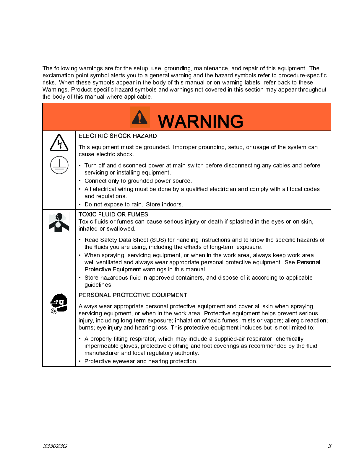
ELECTRIC SHOCK HAZARD
This equipment must be grounded. Improper grounding, setup, or usage of the system can
cause electric shock.
• Turn off and disconnect power at main switch before disconnecting any cables and before
servicing or installing equipment.
• Connect only to grounded power source.
• All electrical wiring must be done by a qualified electrician and comply with all local codes
and regulations.
• Do not expose to rain. Store indoors.
TOXIC FLUID OR FUMES
Toxic fluids or fumes can cause serious injury or death if splashed in the eyes or on skin,
inhaled or swallowed.
• Read Safety Data Sheet (SDS) for handling instructio ns and to know the s pecific hazards of
the fluids you are using, including the effects of long-term exposure.
• When spraying, servicing equipment, or when in the work area, always keep work area
well ventilated and always wear appropriate personal protective equipment. See
Protective Equipment
• Store hazardous fluid in approved containers, and dispose of it according to applicable
guidelines.
PERSONAL PROTECTIVE EQUIPMENT
Always wear appropriate personal protective equipment and cover all skin when spraying,
servicing equipment, or when in the work area. Protective equipment helps prevent serious
injury, including long-term exposure; inhalation of toxic fumes, mists or vapors; allergic reaction;
burns; eye injury and hearing loss. This protective equipment incl udes but is not limited to:
• A properly fitting respirator, which may include a supplied-air respirator, chemically
impermeable gloves, protective clothing and foot coverings as recommended by the fluid
manufacturer and local regulatory authority.
• Protective eyewear and hearing protection.
warnings in this manual.
Personal
333023G 3
Page 4
Warnings
WARNING
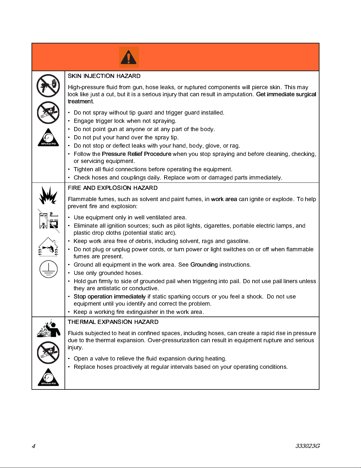
SKIN INJECTION HAZARD
High-pressure fluid from gun, hose leaks, or ruptured components will pierce skin. This may
look like just a cut, but it is a serious injury that can result in amputation.
treatment
• Do not spray without tip guard and trigger guard installed.
• Engage trigger lock when not spraying.
• Do not point gun at anyone or at any part of the body.
• Do not put y our hand over the spray tip.
• Do not stop or deflect leaks with your hand, body, glove, or rag.
• Follow the
or servicing equipment.
• Tighten all fluid connections before operating the equipment.
• Check hoses and couplings daily. Replace worn or damaged parts immediately.
FIRE AND EXPLOSION HAZARD
.
Pressure Relief Procedure
when you stop spraying and before cleaning, checking,
Get immediate surgical
Flammable fumes, such as solvent and paint fumes, in
prevent fire and explosion:
• Use equipment only in well ventilated area.
• Eliminate all ignition sources; such as pilot lights, cigarettes, portable electric lamps, and
plastic drop cloths (potential static arc).
• Keep work area free of debris, including solvent, rags and gasoline.
• Do not plug or unplug power cords, or turn power or light switches on or off when flammable
fumes are present.
• Ground all equipment in the work area. See
• Use on ly grounded hoses.
• Hold gun firmly to side of grounded pail when triggering into pail. Do not use pail liners unless
they are antistatic or conductive.
•
Stop operation immediately
equipment until you identify and correct the problem.
• Keep a working fire extinguisher in the work area.
THERMAL EXPANSION HAZARD
Fluids subjected to heat in confined spaces, including hoses, can create a rapid rise in pressure
due to the thermal expansion. Over-pressurization can result in equipment rupture and serious
injury.
• Open a valve to relieve the fluid expansion during heating.
• Replace hoses proactively at regular intervals based on your operating conditions.
if static sparking occurs or you feel a shock.Do not use
Grounding
work area
instructions.
canigniteorexplode.Tohelp
4
333023G
Page 5

Warnings
WARNING
PRESSURIZED ALUMINUM PARTS HAZARD
Use of fluids that are incompatible with aluminum in pressurized equipment can cause serious
chemical reaction and equipment rupture. Failure to follow this warning can result i n death,
serious injury, or property damage.
• Do not use 1,1,1-trichloroethane, methylene chloride, other halogenated hydrocarbon
solvents or fluids containing such sol vents.
• Many other fluids may contain chemicals that can react with alumi num. Contact your material
supplier for compatibility.
PLASTIC PARTS CLEANING SOLVENT HAZARD
Many solvents can degrade plastic parts and cause them to fail, which could cause serious
injury or property damage.
• Use only compatible water-based solvents to clean plastic structural or pressure-containing
parts.
•See
Technical Data
solvent manufacturer’s MSDSs and recommendations.
in this and all other equipment instruction manuals. Read fluid and
EQUIPMENT MISUSE HAZARD
Misuse can cause death or serious injury.
• Do not operate the unit when fat igued or under the influence of drugs or alcohol.
• Do not exceed the maximum working pressure or temperature rating of the lowest rated
system component. See
• Use fluids and solvents that are compatible with equipment wetted parts. See Te chnical Data
in all equipment manuals. Read fluid and solvent manufacturer’s warnings. For complete
information about your material, request MSDS from distributor or retailer.
• Do not leave the work area while equipment is energized or under pressure.
• Turn off all equipment and follow the
• Check equipment daily. Repair or replace worn or damaged parts immediately with genuine
manufacturer’s replacement parts only.
• Do not alter or mo d ify equipment. Alterations or modifications may void agency approvals
and create safety hazards.
• Make sure all equipment is rated and approv ed for the environm ent in which you are using it.
• Use equipment only for its intended purpose. Call your distributor for information.
• Route hoses and cables away from traffic areas, sharp edges, moving parts, and hot surfaces.
• Do not kink or over bend hoses or use hoses to pull equipment.
• Keep children and animals away from work area.
• Comply with all applicable safety regulations.
MOVING PARTS HAZARD
Technical Data
Pressure Relief Procedure
in all equipment manuals.
when equipment is not in use.
Moving parts can pinch, cut or amputate fingers and other body parts.
• Keep clear of moving parts.
• Do not operate equipment with protective guards or covers removed.
• Pressurized equipment c an start without warning. Before checking, moving, or servicing
equipment, follow the
333023G 5
Pressure Relief Procedure
and disconnect all power sources.
Page 6
Warnings
WARNING
BURN HAZARD
Equipment surfaces and fluid that is heated can become very hot during operation. To avoid
severe burns:
• Do not touch hot fluid or equipment.
6 333023G
Page 7
Important Isocyanate Information
Important Isocyanate Information
Isocyanates (ISO) are catalysts used in two component materials.
Isocyanate Conditions
Spraying or dispensing fluids that contain isocyanates creates potentially harmful mists, vapors, and
atomized particulates.
• Read and understand the fluid manufacturer’s warnings and Safety Data Sheet (SDS) to know specific
hazards and precautions related to isocyanates.
• Use of isocyanates involves potenti a lly hazardous procedures. Do not spray with this equipment unless
you are trained, qualified, and have read and understood the information in this manual and in the fluid
manufacturer’s application instructions and SDS.
• Use of incorrectly maintained or mis-adjusted equipment may result in improperly cured material, which
could cause off gassing and offensive odors. Equipment must be carefully maintained and adjusted
according to instructions in the manual.
• To prevent inhalation of isocyanate mists, vapors and atomized particulates, everyone in the work
area must wear appropriate respiratory protection. Always wear a properly fitting respirator, which
may include a supplied-air respirator. Ventilate the work area according to instructions in the fluid
manufacturer’s SDS.
• Avoid all skin contact with isocyanates. Everyone in the work area must wear chemically impermeable
gloves, protective clothing and foot coverings a s recommended by the fluid manufacturer and local
regulatory authority. Follow all fluid manufacturer recommendations, including those regarding handling
of contaminated clothing. After spraying, wash hands and face before eati ng or drinking.
• Hazard from exposure to isocyanates continues after spraying. Anyone without appropriate persona l
protective equipment must stay out of the work area during application and after application for the time
period specified by the fluid manufacturer. Generally this time period is at least 24 hours.
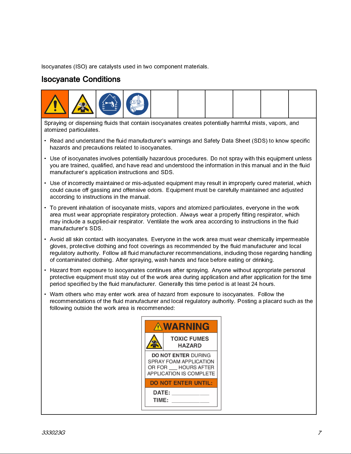
• Warn others who may enter work area of hazard from exposure to isocyanates. Follow the
recommendations of the fluid manufacturer and local regulatory authority. Posting a placard such as the
following outside the work area is recommended:
333023G
7
Page 8
Important Isocyanate Information
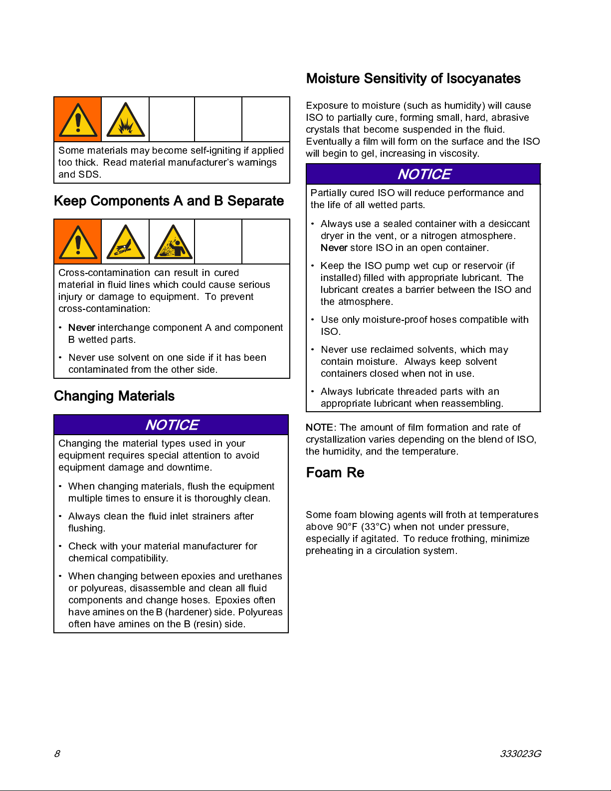
Material Self-Ignition
Some materials may become self-igniting if applied
too thick. Read material manufacturer’s warnings
and SDS.
Keep Components A and B Separate
Cross-contamination can result in cured
material in fluid lines which could cause serious
injury or damage to equipment. To prevent
cross-contamination:
•
Never
interchange component A and component
Bwettedparts.
• Never use solvent on one side if it has been
contaminated from the other side.
Moisture Sensitivity of Isocyanates
Exposure to moisture (such as humidity) will cause
ISO to partially cure, forming small, hard, abrasive
crystals that become suspended in the fluid.
Eventually a film will form on the surface and the ISO
willbegintogel,increasinginviscosity.
NOTICE
Partially cured ISO will reduce performance and
the life of all wetted parts.
• Always use a sealed container with a desiccant
dryer in the vent, or a nitrogen atmosphere.
Never
store ISO in an open container.
• Keep the IS O pump wet cup or reservoir (if
installed) filled with appropriate lubricant. The
lubricant creates a barrier between the ISO and
the atmosphere.
• Use only moisture-proof hoses compatible with
ISO.
• Never use reclaimed solvents, which may
contain moisture. Always keep solvent
containers closed when not in use.
Changing Materials
NOTICE
Changing the material types used in your
equipment requires special attention to avoid
equipment damage and downtime.
• When chan ging materials, flush the equipment
multiple times to ensure it is thoroughly clean.
• Always clean the fluid inlet strainers after
flushing.
• Check with your material manufacturer for
chemical compatibility.
• When changing between epoxies and urethanes
or polyureas, disassemble and clean all fluid
components and change hoses. Epoxies often
have amines on the B (hardener) side. Polyureas
often have amines on the B (resin) side.
• Always lubricate threaded parts with an
appropriate lubricant when reassembling.
NOTE:
crystallization varies depending on the blend of ISO,
the humidity, and the temperature.
The amount of film formation and rate of
Foam Resins with 245 fa Blowing Agents
Some foam blowing agents will froth at temperatures
above 90°F (33°C) when not under pressure,
especially if agitated. To reduce frothing, minimize
preheating in a circulation system.
8 333023G
Page 9
Models
Models
Reactor 2 E-30 and E-30 Elite
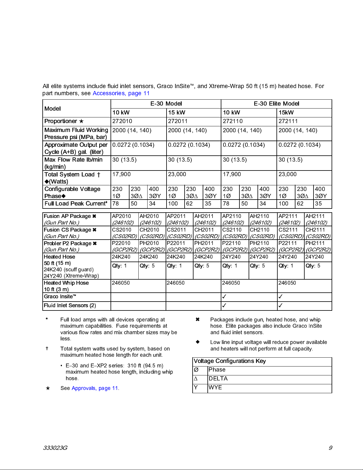
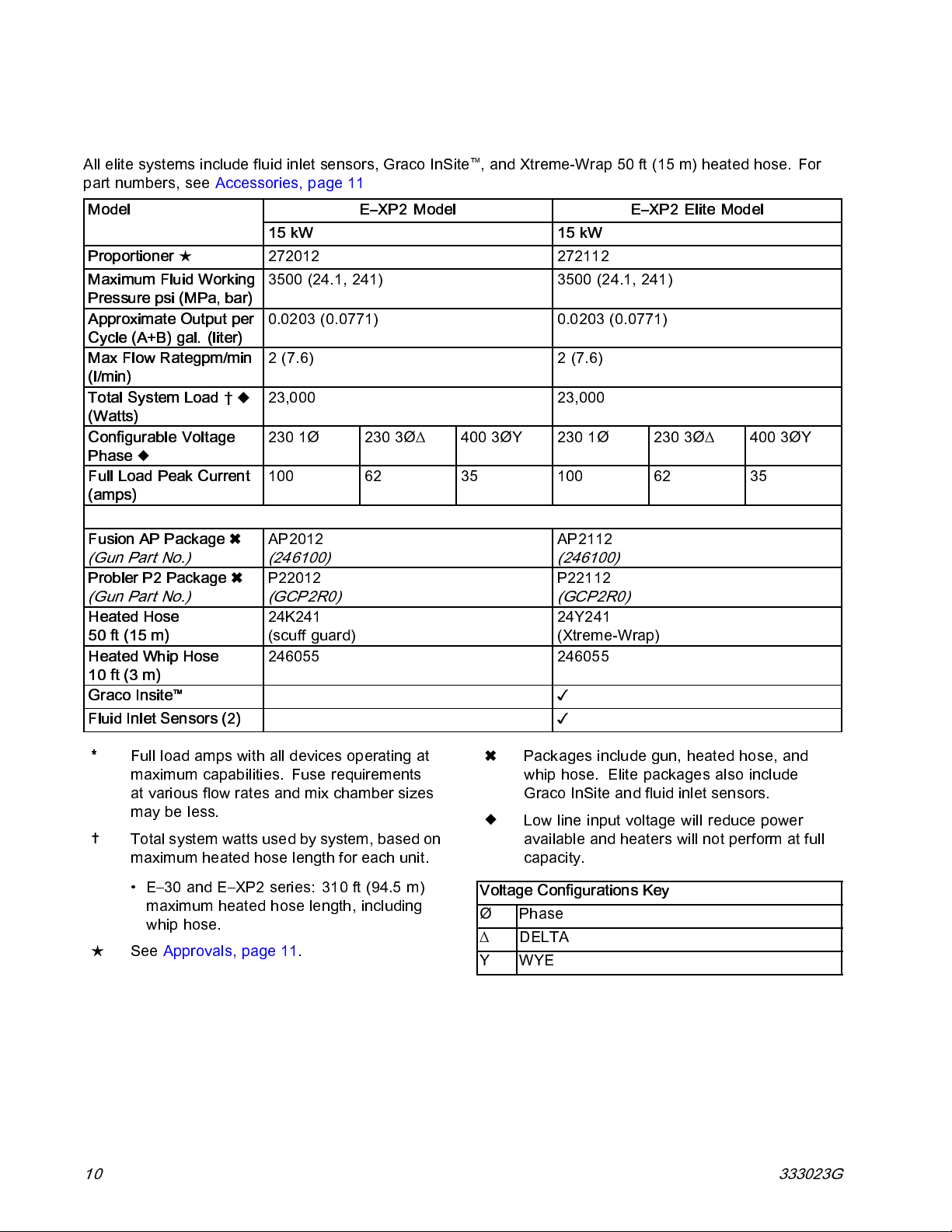
All elite systems include fluid inlet sensors, Graco InSite™, and Xtreme-Wrap 50 ft (15 m) heated hose. For
part numbers, see Accessories, page 11
Model
Proportioner
★ 272010 272011 272110 272111
Maximum Fluid Working
Pressure psi (MPa, bar)
Approximate Output per
Cycle (A+B) gal. (liter)
Max Flow Rate lb/min
(kg/min)
Total System Load †
(Watts)
Configurable Voltage
Phase
Full Load Peak Current*
Fusion AP Package
(Gun Part No.)
Fusion CS Package
(Gun Part No.)
Probler P2 Package
(Gun Part No.)
d Hose
Heate
15 m)
50 ft (
40 (scuff guard)
24K2
40 (Xtreme-Wrap)
24Y2
Heated Whip Hose
10 ft (3 m)
Graco Insite
Fluid Inlet Sensors (2)
™
E-30 Model E-30 Elite Model
10 kW 15 kW 10 kW 15kW
2000 (14, 140) 2000 (14, 140) 2000 (14, 140) 2000 (14, 140)
0.0272 (0.1034) 0.0272 (0.1034) 0.0272 (0.1034) 0.0272 (0.1034)
30 (13.5) 30 (13.5) 30 (13.5) 30 (13.5)
17,900 23,000 17,900 23,000
2301Ø230
3Ø∆
400
3ØY
2301Ø230
3Ø∆
400
3ØY
2301Ø230
3Ø∆
400
3ØY
2301Ø230
3Ø∆
400
3ØY
78 50 34 100 62 35 78 50 34 100 62 35
AP2010
(246102)
CS2010
(CS02RD)
P22010
(GCP2R2)
24K24
Qty:
246050 246050 246050 246050
0
1
AH2010
(246102)
CH2010
(CS02RD)
PH2010
(GCP2R2)
0
24K24
Qty:
5
AP2011
(246102)
CS2011
(CS02RD)
P22011
(GCP2R2)
0
24K24
Qty:
1
AH2011
(246102)
CH2011
(CS02RD)
PH2011
(GCP2R2)
0
24K24
Qty:
5
AP2110
(246102)
CS2110
(CS02RD)
P22110
(GCP2R2)
24Y24
Qty:
✓✓
✓✓
0
1
AH2110
(246102)
CH2110
(CS02RD)
PH2110
(GCP2R2)
0
24Y24
Qty:
5
AP2111
(246102)
CS2111
(CS02RD)
P22111
(GCP2R2)
24Y24024Y24
Qty:
1
AH2111
(246102)
CH2111
(CS02RD)
PH2111
(GCP2R2)
Qty:
0
5
Full load amps with all devices operating at
*
maximum capabilities. Fuse requirements at
various flow rates and mix chamber sizes may be
less.
Total system watts used by system, based on
maximum heated hose length for each unit.
• E–30 and E–XP2 series: 310 ft (94.5 m)
maximum heated hose length, including whip
hose.
★
See Approvals, page 11.
Packages include gun, heated hose, and whip
hose. Elite packages also include Graco InSite
and fluid inlet sensors.
Low line input voltage will reduce power available
and heaters will not perform at full capacity.
Voltage Configurations Key
Phase
Ø
∆
DELTA
YWYE
333023G 9
Page 10
Models
Reactor 2 E-XP2 and E-XP2 Elite
All elite systems include fluid inlet sensors, Graco InSite™, and Xtreme-Wrap 50 ft (15 m) heated hose. For
part numbers, see Accessories, page 11
Model
Proportioner
Maximum Fluid Working
Pressure psi (MPa, bar)
Approximate Output per
Cycle (A+B) gal. ( liter)
Max Flow Rategpm/min
(l/min)
Total System Load †
(Watts)
Configurable Voltage
Phase
Full Load Peak Current
(amps)
Fusion AP Package
(Gun Part No.)
Probler P2 Package
(Gun Part No.)
Heated Hose
50 ft (15 m)
Heated Whip Hose
10 ft (3 m)
Graco Insite
Fluid Inlet Sensors (2)
★ 272012 272112
™
E–XP2 Model E–XP2 Elite Model
15 kW 15 kW
3500 (24.1, 241) 3500 (24.1, 241)
0.0203 (0.0771) 0.0203 (0.0771)
2 (7.6) 2 (7.6)
23,000 23,000
230 1Ø 230 3Ø∆ 400 3ØY 230 1Ø 230 3Ø∆ 400 3ØY
100 62 35 100 62 35
AP2012
(246100)
P22012
(GCP2R0)
24K241
(scuff guard)
246055 246055
AP2112
(246100)
P22112
(GCP2R0)
24Y241
(Xtreme-Wrap)
✓
✓
Full load amps with all devices operating at
*
maximum capabilities. Fuse requirements
at various flow rates and mix chamber sizes
may be less.
Total system watts used by system, based on
maximum heated hose length for each unit.
• E–30 and E–XP2 series: 310 ft (94.5 m)
maximum heated hose length, including
whip hose.
★
See Approvals, page 11.
10 333023G
Packages include gun, heated hose, and
whip hose. Elite packages also include
GracoInSiteandfluidinletsensors.
Low line input voltage will reduce power
available and heaters will not perform at full
capacity.
Voltage Configurations Key
Phase
Ø
∆
DELTA
YWYE
Page 11
Approvals
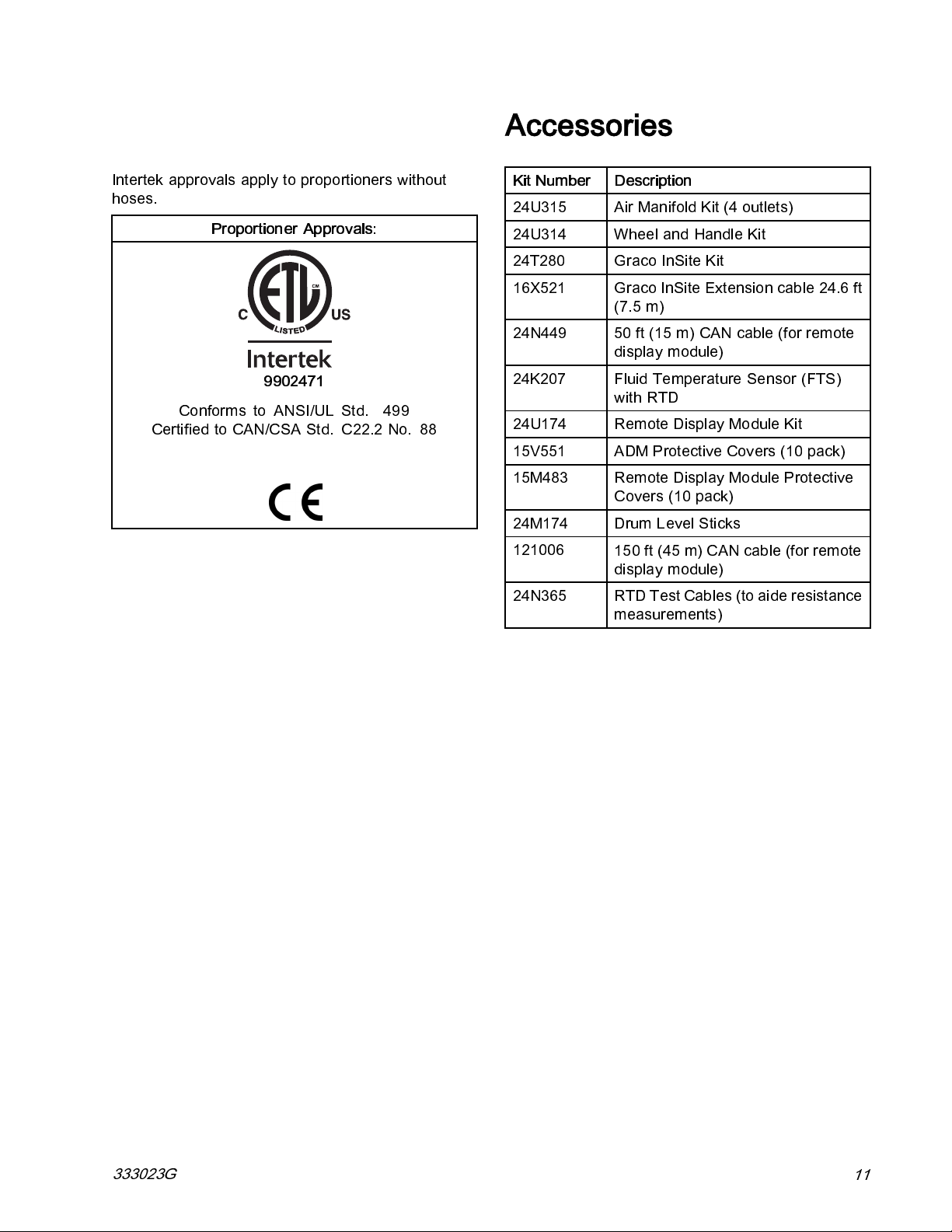
Approvals
Intertek approvals apply to proportioners without
hoses.
Proportioner Approvals:
9902471
Conforms to ANSI/UL Std. 499
Certified to CAN/CS A Std. C22.2 No. 88
Accessories
Kit Number Description
24U315
24U314 Wheel and Handle Kit
24T280
16X521
24N449 50 ft (15 m) CAN cable (for remote
24K207
24U174 Remote Display Module Kit
15V551
15M483 Remote Display Module Protective
24M174
121006
Air Manifold Kit (4 outlets)
GracoInSiteKit
GracoInSiteExtensioncable24.6ft
(7.5 m)
display module)
Fluid Temperature Sensor (FTS)
with RTD
ADM Protective Covers (10 pack)
Covers (10 pack)
Drum Level Sticks
150 ft (45 m) CAN cable (for remote
display module)
24N365
RTD Test Cables (to aide resistance
measurements)
333023G
11
Page 12
Supplied Manuals
Supplied Manuals
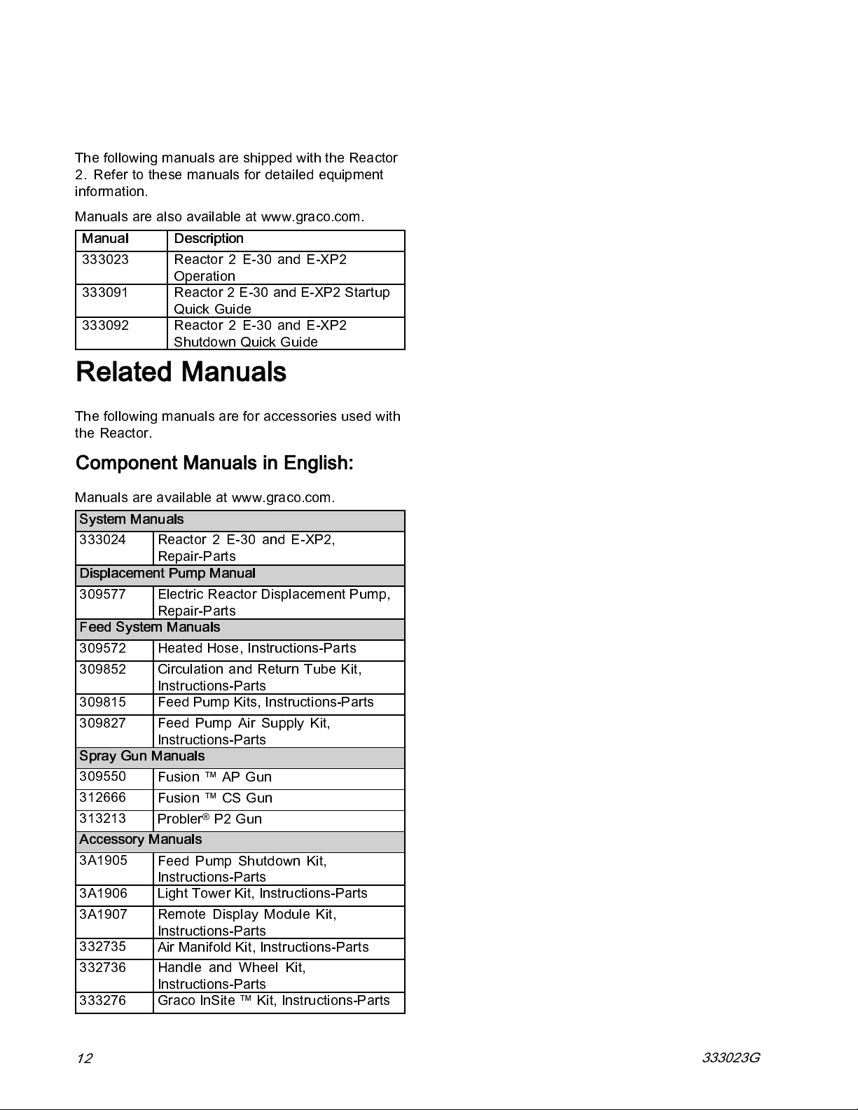
The following manuals are shipped with the Reactor
2. Refer to these manuals for detailed equipment
information.
Manuals are also available at www.graco.com.
Manual Description
333023 Reactor 2 E-30 and E-XP2
Operation
333091
333092 Reactor 2 E-30 and E-XP2
Reactor 2 E-30 and E-XP2 Startup
Quick Guide
Shutdown Quick Guide
Related Manuals
The following manuals are for accessories used with
the Reactor.
Component Manuals in English:
Manuals are available at www.graco.com.
System Manuals
333024 Reactor 2 E-30 and E-XP2,
Repair-Parts
Displacement Pump Manual
309577 Electric Reactor Displacement Pump,
Repair-Parts
Feed System Manuals
309572 Heated Hose, Instructions-Parts
309852
309815 Feed Pump Kits, Instructions-Parts
309827
Spray Gun Manuals
309550
312666
313213
Accessory Manuals
3A1905
3A1906 Light Tower Kit, Instructions-Parts
3A1907 Remote Display Module Kit,
332735
332736 Handle and Wheel Kit,
333276
Circulation and Return Tube Kit,
Instructions-Parts
Feed Pump Air Supply Kit,
Instructions-Parts
Fusion ™ AP Gun
Fusion ™ CS Gun
®
Probler
Feed Pump Shutdown Kit,
Instructions-Parts
Instructions-Parts
Air Manifold Kit, Instructions-Parts
Instructions-Parts
Graco InSite ™ Kit, Instructions-Parts
P2 Gun
12
333023G
Page 13
Typical Installation, without circulation
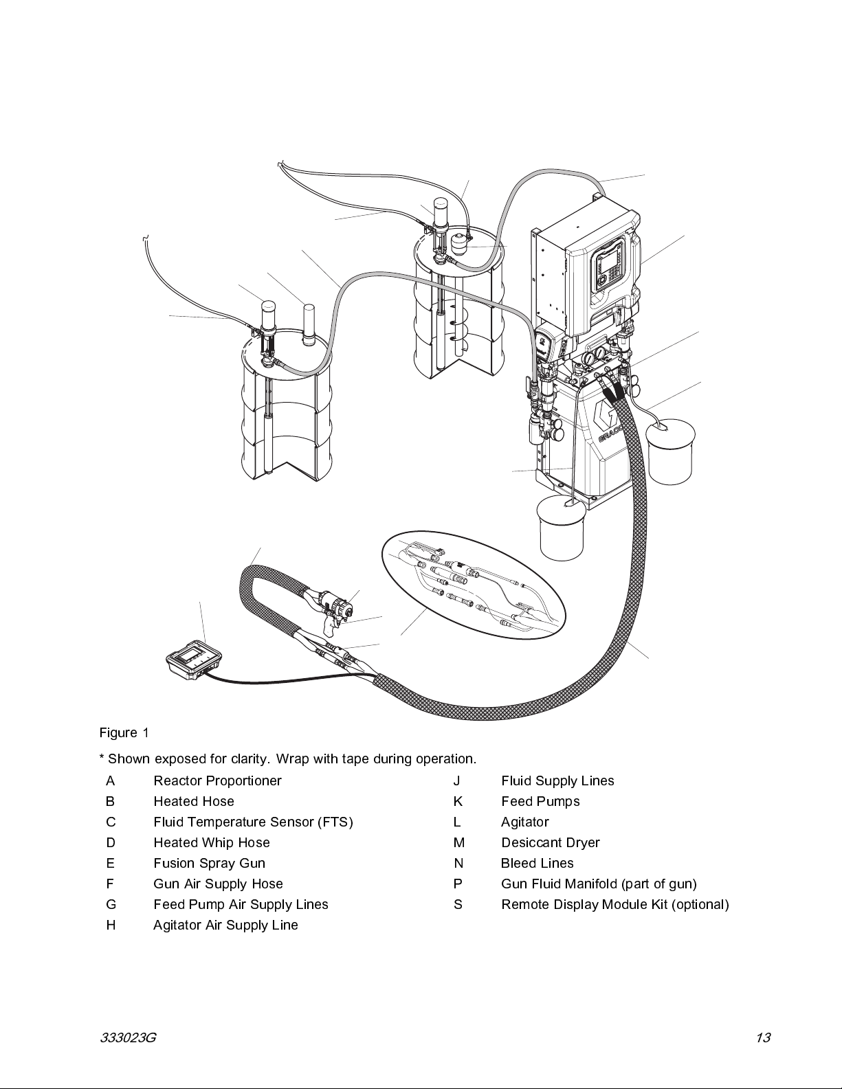
Typical Installation, without circulation
H
K
G
J
M
K
G
L
J
A
F
N
(RES)
N
(ISO)
D
S
Figure 1
* Shown exposed for clarity. Wrap with tape during operation.
A Reactor Proportioner
BHeatedHose
C Fluid Temperature Sensor (FTS)
D HeatedWhipHose
E
F
G Feed Pump Air Supply Lines
H
Fusion Spray Gun
Gun Air Supply Hose
Agitator Air Supply Line
E
P
C*
J
K Feed Pumps
L Agitator
MDesiccantDryer
NBleedLines
P
S Remote Display Module Kit (optional)
B
Fluid Supply Lines
Gun Fluid Manifold (part of gun)
333023G 13
Page 14
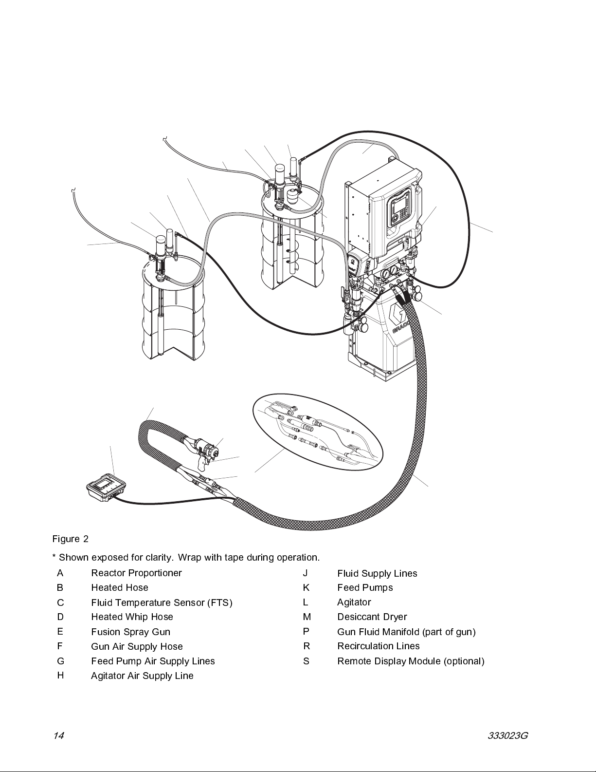
Typical Installation, with system fluid manifold to drum circulation
Typical Installation, with system fluid manifold to drum
circulation
M
K
H
G
J
R
M
K
G
J
A
L
R
(RES)
F
(ISO)
D
S
Figure 2
* Shown exposed for clarity. Wrap with tape during operation.
A Reactor Proportioner
BHeatedHose
C Fluid Temperature Sensor (FTS)
D Heated Whip Hose
E
F
G Feed Pump Air Supply Lines
H
Fusion Spray Gun
Gun Air Supply Hose
Agitator Air Supply Line
E
P
C*
J
K Feed Pumps
L Agitator
M Desiccant Dryer
P
R Recirculation Lines
S Remote Display Module (optional)
B
Fluid Supply Lines
Gun Fluid Manifold (part of gun)
14
333023G
Page 15
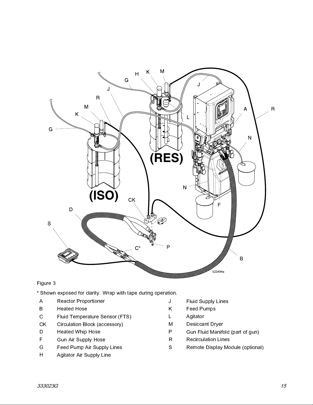
Typical Installation, with gun fluidmanifoldtodrumcirculation
Typical Installation, with gun fluid manifold to drum
circulation
Figure 3
* Shown exposed for clarity. Wrap with tape during operation.
A Reactor Proportioner
BHeatedHose
C Fluid Temperature Sensor (FTS)
CK Circulation Block (accessory)
D HeatedWhipHose
F
G Feed Pump Air Supply Lines
H
333023G 15
Gun Air Supply Hose
Agitator Air Supply Line
J
K Feed Pumps
L Agitator
MDesiccantDryer
P
R Recirculation Lines
S Remote Display Module (optional)
Fluid Supply Lines
Gun Fluid Manifold (part of gun)
Page 16
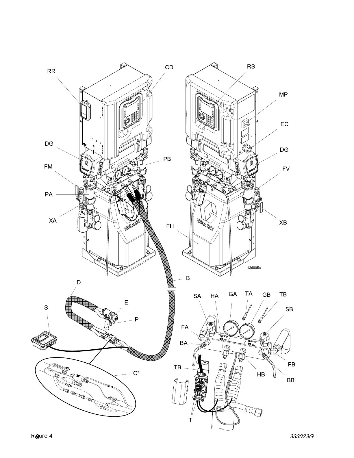
Component Identification
Component Identification
Figure 4
16 333023G
Page 17

Key
BA
BB
CD Advanced Disp
DG Drive Gear Hou
EC Electrical C
EM Electric Motor
FA
FB
FH
FM
FV
GA ISO Side Pre
GB RES Side Pr
HA
HB
MP
PA
PB
RR
ISO Side Pressure Relief Outlet
RES Side Pressure Relief Outlet
ord Strain Relief
ISO Side Flui
RES Side Flui
Fluid Heate
Reactor Flu
Fluid Inlet
ISO Side Ho
RES Side H
Main Powe
ISO Side P
RES Side P
Graco InS
only)
rs (behind shroud)
id Manifold
Valve(RESsideshown)
rSwitch
ump
ite Cellular Module (Elite models
lay Module (ADM)
sing
d Manifold Inlet
d Manifold Inlet
ssure Gauge
essure Gauge
se Connection
ose Connection
ump
Component Identification
RS Red Stop Button
SA ISO Side PRESSURE RELIEF/SPRAY
SB RES Side PRESSURE RELIEF/SPRAY
T Heated Hose Power Termination Box
TA
TB
XA
XB Fluid Inlet Sensor (RES side, Elite models
Valve
Valve
ISO Side Pressure Transducer (behind
gauge GA)
RES Side Pressure Transducer (behind
gauge GB)
Fluid Inlet Sensor (ISO side, Elite models
only)
only)
333023G
17
Page 18

Advanced Display Module (ADM)
Advanced Display Module (ADM)
The ADM display shows graphical and text
information related to setup and spray operations.
NOTICE
To prevent damage to the softkey buttons, do not
press buttons with sharp objects such as pens,
plastic cards, or fingernails.
Figure 5 Front View
18 333023G
Page 19
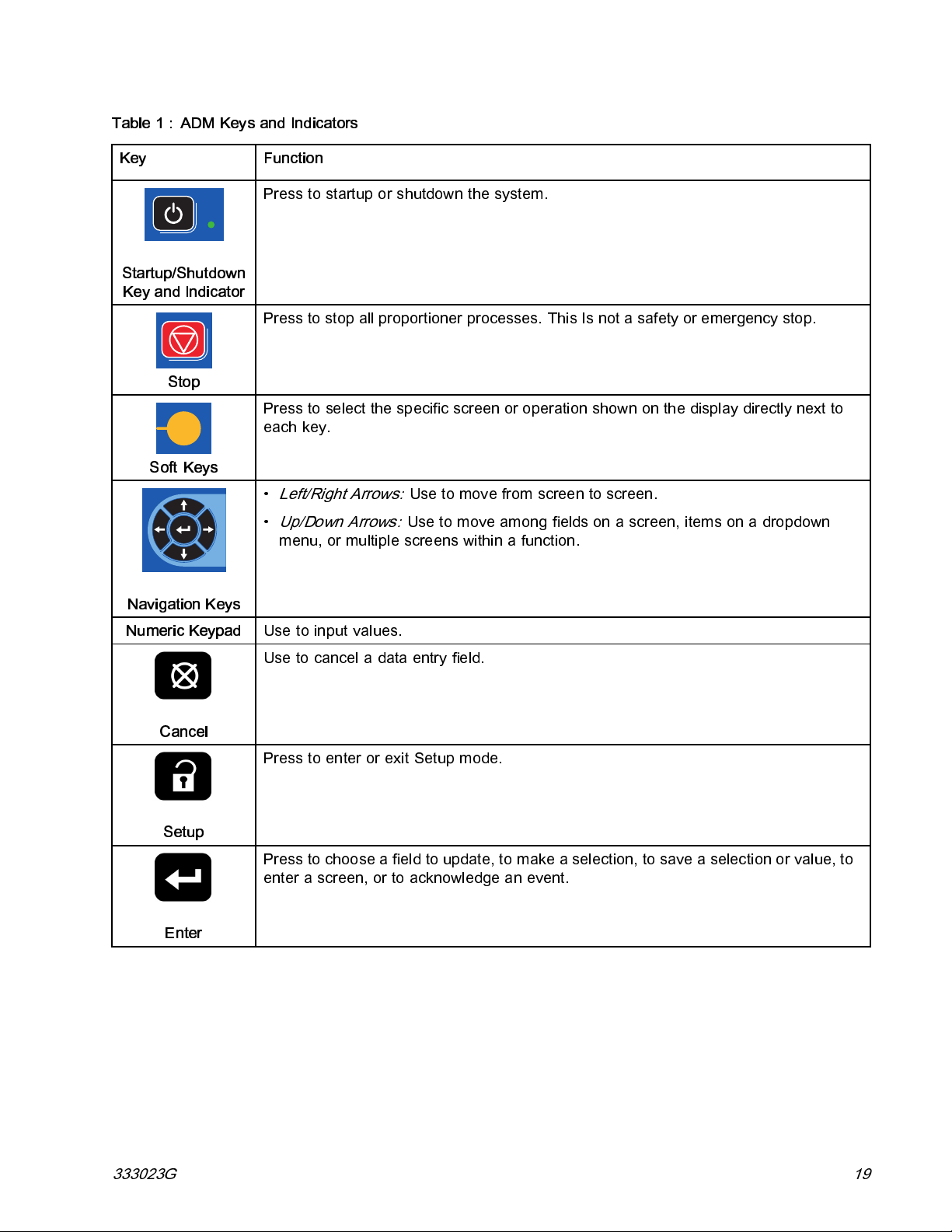
Table 1 : ADM Keys and Indicators
Key Function
Press to startup or shutdown the system.
Advanced Display Module (ADM)
Startup/Shu
Key and Indic
Soft Keys
Navigation Keys
Numeric Keypad
tdown
ator
Stop
Press to stop all proportioner processes. This Is not a safety or emergency stop.
Press to select the specific screen or operation shown on the display directly next to
each key.
•
Left/Right Arrows:
•
Up/Down Arrows:
menu, or multiple screens within a function.
Use to input values.
Usetocanceladataentryfield.
Usetomovefromscreentoscreen.
Usetomoveamongfieldsonascreen,itemsonadropdown
Cancel
Press to enter or exit Setup mode.
Setup
Press to choose a field to update, to make a selection, to save a selection or value, to
enter a screen, or to acknowledge an event.
Enter
333023G 19
Page 20

Advanced Display Module (ADM)
Figure 6 Back View
CJ Flat Panel Mount (VESA 100)
CK Model and Serial Num ber
CL USB Port and Status LEDs
CM CAN Cable Connection
Table 2 ADM LED Status Descriptions
LED
System Status
USB Status (CL)
ADM Status (CN)
CN Module Status LEDs
CP Accessory Cable Connection
CR Token Access Cover
CS Battery Access Cover
Conditions
Green Solid Run Mode, System On
Green Flashing Setup Mode, System On
Yellow Solid Run Mode, System Off
Yellow Flashing
Green Flashing
Yellow Solid Downloading information to USB
Green and Yellow Flashing ADM is busy, USB cannot transfer
Green Solid
Yellow Solid Active Communication
Description
Setup Mode, System Off
Data recording in progress
informationwheninthismode
Power applied to module
Red Steady Flashing Software upload from token in
progress
Red Random Flashing or Solid
20 333023G
Module error exists
Page 21

Advanced Display Module (ADM)
ADM Display Details
Power Up Screen
The following screen appears when the ADM is
powered up. It remains on while the ADM runs through
initialization and establishes communication with other
modules in the system.
Menu Bar
The menu bar appears at the top of each screen. (The
following image is only an example.)
Alarm/Deviation
The current system error is displayed in the middle of
the menu bar. There are four possibilities:
Icon Function
No Icon
Status
The current system status is displayed at the lower right
of the menu bar.
No information or no error has occurred
Advisory
Deviation
Alarm
Soft Keys
Icons next to the soft keys indicate which mode or
action is associated with each soft key. Soft keys that
do not have an icon next to them are not active in the
current screen.
NOTICE
To prevent damage to the soft key buttons, do not
press buttons with sharp objects such as pens, plastic
cards, or fingernails.
Date and Time
The date and time are always displayed in one of the
following formats. The time is always displayed as a
24-hour clock.
MM/YY HH:MM
• DD/
/MM/DD HH:MM
•YY
/DD/YY HH:MM
•MM
Arrows
The left and right arrows indicate screen navigation.
creen Menu
S
The screen menu indicates the currently active screen,
which is highlighted. It also indicates the associated
screens that are available by scrolling left and right.
System Mode
The current system mode is displayed at the lower left
of the menu bar.
Navigating the Screens
Therearetwosetsofscreens:
• The Run s creens control spraying operations and
display system status and data.
• The Setup screens control system parameters and
advanced features.
Press
screens. If the system has a password lock, the
Password screen displays. If the system is not locked
(password is set to 0000), System Screen 1 displays.
Press
Home screen.
Press the Enter soft key
function on any screen.
Press the Exit soft key
Use the other softkeys to select the function adjacent
to them.
on any Run screen to enter the Setup
on any Setup screen to return to the
to activate the editing
to exit any screen.
333023G
21
Page 22

Advanced Display Module (ADM)
Icons
Icons
Icon Function
Component A
Component B
Estimated Supply Material
Hose Temperature
Jog Mode Speed
Pressure
Cycle Counter (press and
hold)
Advisory.
See Errors, page 38 for more
information.
Deviation.
See Errors, page 38 for more
information
Alarm.
See Errors, page 38 for more
information
Softkeys
Icon Function
Start Proportioner
Start and Stop Proportioner in Jog Mode
Stop Proportioner
Turn on or off the specified heat zone.
Park pump
Enter Jog Mode. See Jog Mode, page 46
Reset Cycle Counter
(press and hold)
Select Recipe
Search
Move Cursor Left One Character
Move Cursor Right One Character
Toggle between upper-case, lower-case, and
numbers and special characters.
Backspace
22
Cancel
Clear
Troubleshoot Selected Error
Increase value
Decrease value
Next screen
Previous screen
Return to first screen
333023G
Page 23

Electrical Enclosure
Electrical Enclosure
AAA Temperature Control Module (TCM)
AAB Motor Control Module (MCM)
AAC Enclosure Fan
AAD Wiring Terminal Blocks
AAE Power Supply
AAF Surge Protector
AAG Hose Breaker
AAH Motor Breaker
AAJ A Side Heat Breaker
AAK B Side Heat Breaker
AAL Transformer Breaker
MP Main Power Switch
333023G 23
Page 24

Motor Control Module (MCM)
Motor Control Module
(MCM)
Base Model Elite Model
Figure 7
Description
MS Module Status LEDs see LED Status Table
1
2 Motor Temperature
3 Not used
4 Not used
5 Not used
6
7
8
9
Table 3 MCM Module LED (MS) Status Descriptions
LED
MCM Status
CAN Communication Connections
A Pump Output Pressure
B Pump Output Pressure
A Fluid Inlet Sensor (Elite only)
B Fluid Inlet Sensor (Elite only)
Conditions
Green Solid
Yellow Flashing
Red Steady Flashing Software upload from token in
10 Accessory output
11 Not used
12
14
15
16 Main Power Input
*
RS Rotary Switch
* MCM Rotary Switch Positions
2=E-30
3=E-XP2
Pump Cycle Counter
Graco Insite
Motor Power Output
™
Description
Power applied to module
Active Communication
progress
24
Red Random Flashing or Solid
Module error exists
333023G
Page 25

Temperature Control Module (TCM) Cable Connections
Temperature Control Module (TCM) Cable Connections
Figure 8
1 Power Input
2
3
4
5
6
7
8
9
10 Hose Temperature
Table 4 TCM Module LED (7) Status Descriptions
LED
TCM Status
Heater Overtemperature
CAN Communications Connections
Power Out (ISO)
Power Out (Res)
Power Out (Hose)
Module Status LEDs
Heater A Temperature (ISO)
Heater B Temperature (RES)
Conditions
Green Solid
Yellow Flashing
Red Steady Flashing Software upload from token in
Red Random Flashing or Solid
Description
Power applied to module
Active Communication
progress
Module error exists
333023G 25
Page 26

Installation
Installation
Setup From Shipping Configuration
1. Remove bolts (A) and nuts.
2. Swing up the electrical enclosure and reins tal l
bolt (A) with nut. Tighten bolt (B) and nut.
3. Position cable bundles against the frame and
attach to the frame with loose wire tie (C) on
each side.
1. Use the supplied bolts to install the sup plied
L-brackets onto the system frame in the top-most
square holes. Install brackets on both the left
and right side of system frame.
2. Secure the L-brackets to the wall. If L-brackets
donotlineupwiththewallstudspacing,bolta
piece of wood to the studs then secure L -brackets
to wood.
3. Use the four holes in the base of the system
frame to secure base to the floor. Bolts not
supplied.
To prevent serious injury due to system tipping
over, ensure Reactor is properly secured to wall.
Note
Mounting brackets and bolts are included in the box
of loose parts, shipped with your system.
26 333023G
Page 27
Setup
Setup
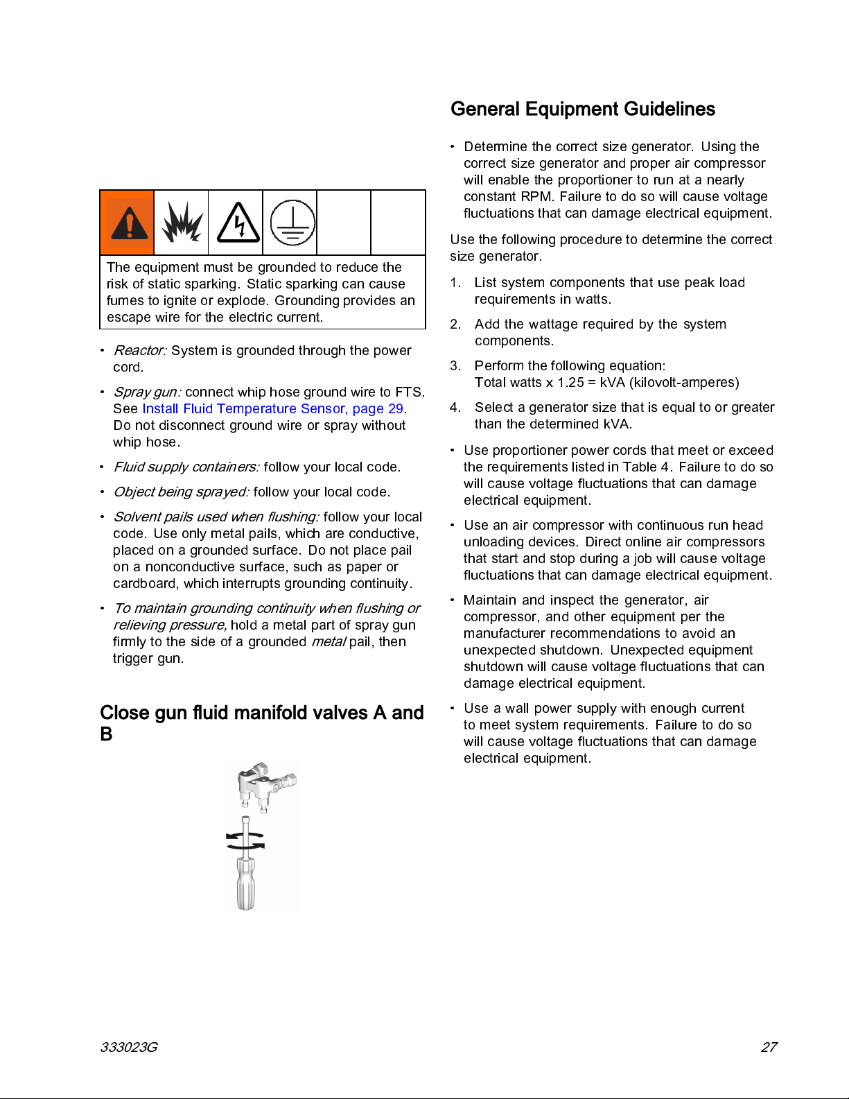
Grounding
The equipment must be grounded to reduce the
risk of static sparking. Static sparking can cause
fumes to ignite or explode. Grounding provides an
escape wire for the electric current.
•
Reactor:
cord.
•
Spray gun:
See Install Fluid Temperature Sensor, page 29.
Do not disconnect ground wire or sp ray without
whip hose.
•
Fluid supply containers:
•
Object being sprayed:
•
Solvent pails used when flushing:
code. Use only metal pails, which are conductive,
placed on a grounded surface. Do not place pail
on a nonconductive surface, such as paper or
cardboard, which interrupts grounding continuity.
•
To maintain grounding continuity when flushing or
relieving pressure,
firmly to the side of a grounded
trigger gun.
System is grounded through the power
connect whip hose ground wire to FTS.
follow your local code.
follow your local code.
follow your local
hold a metal part of spray gun
metal
pail, then
General Equipment Guidelines
• Determine th e correct size generator. Using the
correct size generator and proper air compressor
will enable the proportioner to run at a nearly
constantRPM.Failuretodosowillcausevoltage
fluctuations that can damage electrical equipment.
Use the following procedure to determine the correct
size generator.
1. List system components that use peak load
requirements in watts.
2. Add the wattage required by the system
components.
3. Perform the following equation:
Total watts x 1.25 = kVA (kilovolt-am peres )
4. Select a generator size that is equal to or greater
than the determined kVA.
• Use proportioner power cords that meet or exceed
therequirementslistedinTable4.Failuretodoso
will cause voltage fluctuations that can damage
electrical equipment.
• Use an air compressor with continuous run head
unloading devices. Direct online air compressors
that start and stop during a job will cause voltage
fluctuations that can damage electrical equipment.
• Maintain and inspect the generator, air
compressor, and other equipment per the
manufacturer recommendations to avoid an
unexpected shutdown. Unexpected equipment
shutdown will cause voltage fluctuations that can
damage electrical equipment.
Close gun fluid manifold valves A and
B
333023G
• Use a wall power supply with enough current
to meet system requirements. Failure to do so
will cause voltage fluctuations that can damage
electrical equipment.
27
Page 28

Setup
Connect Power
All electrical wiring must be done by a qualified
electrician and comply with all local codes and
regulations.
1. Turn main power switch (MP) OFF.
2. Open electrical enclosure door.
NOTE:
Terminal jumpers are located inside the
electrical enclosure door.
3. Install supplied terminal jumpers in the positions
shown in image for the power source used.
4. Route power cable through strain relief (EC) in
electrical enclosure.
5. Connect incoming power wires as shown in
image. Gently pull on all connections to verify
they are properly secured.
6. Verify all items are connected properly as shown
in image then close electrical enclosure door.
Table 5 Power Cord Requirements
Model Input Power
E-30, 10 kW
200–240 VAC,
1Phase
200–240 VAC,
3 Phase,
DELTA
350–415 VAC,
3 Phase, WYE
E-30, 15 kW
200–240 VAC,
1Phase
200–240 VAC,
3 Phase,
DELTA
350–415 VAC,
3 Phase, WYE
Cord
Specifications
AWG (mm
2
)
4 (21.2), 2 wire
+ ground
6(13.3),3wire
+ground
8 (8.4), 4 wire
+ground
4 (21.2), 2 wire
+ ground
6(13.3),3wire
+ground
8 (8.4), 4 wire
+ground
Model Input Power
E-XP2, 15 kW
200–240 VAC,
1Phase
200–240 VAC,
3Phase,
DELTA
350–415 VAC,
3 Phase, WYE
Cord
Specifications
AWG (mm
2
)
4 (21.2), 2 wire
+ ground
6(13.3),3wire
+ground
8(8.4),4wire
+ground
28 333023G
Page 29

Supply Wet Cups With Throat Seal Liquid (TSL)
Pump rod and connecting rod m ove during
operation. Moving parts can cause serious injury
such as pinching or amputation. Keep hands and
fingers away from wet-cup during operation.
To prevent the pump from moving, turn the main
power switch OFF.
•
Component A (ISO) Pump:
with Graco Throat Seal Liquid (TSL), Part 206995.
Wet-cup piston circulates TSL through wet-cup, to
carry away isocyanate film on displacement rod.
Keep reservoir (R) filled
Setup
•
Component B (Resin) Pump:
in packing nut/wet-cup (S) daily. Keep saturated
with Graco Throat Seal Liquid (TSL), Part No.
206995, to prev en t material from hardening on
displacement rod. Replace felt washers when worn
or contaminated with hardened material.
Figure 10 Component B Pump
Check felt washers
Install Fluid Temperature Sensor
Figure 9 Component A Pump
The Fluid Temperature Sensor (FTS) is supplied.
Install FTS between main hose and whip hose. See
Heated Hose manual for instructions.
333023G 29
Page 30

Setup
Connect Heated Hose to Proportioner
See the heated hose manual for detailed instructions.
1. For proportioners with termination box (TB):
a. Connect hose power wires to terminal block
(T) on termination box (TB). Remove box
cover and loosen lower strain relief (E).
Route hose wires (V) through the box strain
relief and fully insert into terminal block (T). A
and B hose wire positions are not important.
Torque to 26–30 in-lbs (2.9–3.3 N·m).
b. Fully tighten strain relief screws and replace
cover.
a. Connect hose power wires to electrical splice
connectors (S) from proportioner. Wrap
connections with electrical tape.
Figure 12 Electrical Splice Connectors
3. Connect FTS cable connectors (R). Fully tighten
RTD connectors, if provided.
Figure 11 Termination Box
2. For proportioners with elec tric al splice connectors
(S):
Register and Activate the Graco InSite
Note
Elite systems only.
1. Go to www.GracoInSite.com, then follow the
instructions on the screen.
2. Find and record the 15 di gi t serial numb er from
the cellular module below.
30 333023G
Page 31

Advanced Display Module (ADM) Operation
Advanced Display Module (ADM) Operation
When main power is turned on by turning the main
power switch (MP) to the ON position, the power up
screen will be displayed until communication and
initialization is complete.
Then the power key icon screen will display until the
ADM power on/off button (A)
first time after system power-up.
To begin using the ADM, the machine must be active.
To verify the machine is active, verify that the System
Status Indicator Light (B) is illuminated green, see
Advanced Display Module (ADM), page 18.Ifthe
System Status Indicator Light is not green, press
the ADM Power On/Off (A) button
Status Indicator Light will illuminate yellow if the
machine is disabled.
is pressed for the
. The System
Perform t
1. Set pressure values for the Pressure Imbalance
2. Enter, enable, or disable recip es. See
3. Set general system settings. See
4. Set units of measure. See
5. Set USB settings. See
6. Set target temperatures and pressure. See
7. Set component A and component B supply
he following tasks to fully setup your system.
Alarm to activate. See System Screen 1, page 35.
Recipes Screen, page 35.
Advanced Screen 1 — General, page 34.
Advanced Screen 2 — Units, page 34.
Advanced Screen 3— USB, page 34.
Targets, page 37.
levels. See Maintenance, page 38.
333023G 31
Page 32

Advanced Display Module (ADM) Operation
Setup Mode
The ADM will start i n the Run screens at the Home screen. From the Run screens, press to
access the Setup screens. The system defaults with no password, entered as 0000. Enter the
current password then press
Setup Screens Navigation Diagram, page 45.
.Press to navigate through the Setup Mode screens. See
Set Password
Set a password to allow Setup screen access, see Advanced Screen 1 – General, page 34. Enter any number
from 0001 to 9999. To remove the password, enter the current password in the Advanced Screen – General
screen and change the password to 0000.
From the Setup screens, press to return to the Run screens.
32 333023G
Page 33

Advanced Display Module (ADM) Operation
Setup Screens Navigation Diagram
Figure 13
333023G 33
Page 34
Advanced Setup Screens
Advanced Setup Screens
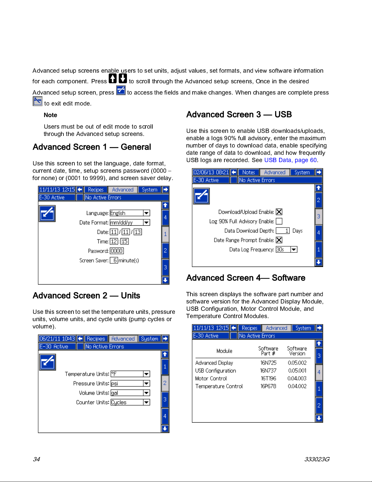
Advanced setup screens enable users to set units, adjust values, set formats, and view software information
for each component. Press
Advanced setup screen, press
to exit edit mode.
Note
Users must
through th
be out of edit mode to scroll
e Advanced setup screens.
to scroll through the Advanced setup screens, Once i n the desired
to access the fields and make changes. When changes are complete press
Advanced Screen 1 — General
Use this screen to set the langu age, date format,
current date, time, setup screens password (0000 –
for none) or (0001 to 9999), and screen saver delay.
Advanced Screen 3 — USB
UsethisscreentoenableUSBdownloads/uploads,
enable a logs 90% full advisory, enter the maximum
number of days to download data, enable specifying
date range of data to download, and how frequently
USB logs are recorded. See USB Data, page 60.
Advanced Screen 2 — Units
Use this screen to set the temperature units, pressure
units, volume units, and cycle units (pump cycles or
volume).
Advanced Screen 4— Software
This screen displays the software part number and
software version for the Advanced Display Module,
USB Configuration, Motor Control Module, and
Temperature Control Modules.
34 333023G
Page 35

System 1
System 1
Use this screen to set the activation pressure for the
Pressure Imbalance Alarm and Deviation, enable or
disable diagnostic screens, set the maximum and
minimum drum volume, and enable drum alarms.
System 2
Recipes
Use this screen to add recipes, view saved recipes,
and enable or disable saved recipes. Enabled
recipes can be selected at the Home Run Screen. 24
recipescandisplayedonthethreerecipescreens.
Add Reci
pe
Use this screen to enable Manu al Hose Mode and
inlet sensors, as well as setting the i nlet sensor
low pressure alarm and low temperature deviation.
Manual Hose Mode disables the hose temperature
RTD sensor so the system can operate if the sensors
were to malfunction. Default settings are 10 psi (0.07
MPa, 0.7 bar) for low inlet pressure alarm and 50˚F
(10˚C) for low inlet temperature deviation.
1. Press and then use to select a
recipe field. Press
(maximum 16 characters). Press
oldrecipename.
2.Use to highlight the next field and use the
number pad to enter a value. Press
toenterarecipename
to clear the
to save.
Enable or Disable Recipes
1. Press and then use to select the
recipe that needs to be enabled or disabled.
2.Use
Press
333023G 35
to highlight the enabled check box.
to enable or disable the recipe.
Page 36

Run Mode
Run Mode
The ADM will st
screens. See R
From the Run sc
to access the Setup screens.
art in the Run screens at the “Home” screen. Press
un Screens Navigation Diagram, page 44.
reens, press
to navigate through the Run Mode
36 333023G
Run Screens Navigation Diagram
Page 37

Run Mode
Home — System Off
This is the home screen when the system is off.
This screen displays actual temperatures, actual
pressures at the fluid manifold, jog speed, coolant
temperature, and number of cycles.
Home — System Active
When the system is active, the home screen displays
actual temperature for heat zones, actual pressures
at the fluid manifold, coolant temperature, jog speed,
the number of cycles, along with all associated
control soft keys.
Home — System With Error
Active errors are shown in the status bar. The error
code, alarm bell, and description of the error will
scroll in the status bar.
1. Press
2.SeeTroubleshooting, page 59 for corrective
action.
to acknowledge the error.
Targets
Usethisscreentodefinethesetpointsforthe
A Component Temperature, B Component
Temperature, heated hose temperature, and
pressure.
Maximum A and B temperature:
Maximum heated hose temperature:
above the highest A or B temperature setpoint or
180°F (82°C).
Note
If the remote display module kit is used,
these setpoints can be modified at the gun.
190°F (88°C)
10°F (5°C)
Use this screen to turn on heat zones, view
coolant temperature, start the proportioner, stop the
proportioner, park the component A pump, enter jog
mode, and clear cycles.
NOTE:
temperatures and pressures. These will not be
shown on models without inlet sensors.
Screen shown displays inlet sensor
333023G 37
Page 38

Run Mode
Maintenance
Use this screen to view daily and lifetime cycles or
gallons that have been pumped and gallons or liters
remaining in the drums.
The lifetime value is the number of pump cycles or
gallons since the first time the ADM was turned on.
The daily value automatically resets at midnight.
The manual value is the counter that can be manually
reset. Press
and hold to reset manual counter.
Events
This screen shows the date, time, event code, and
description of all events that have occurred on
the system. There are 10 pages, each holding 10
events. The 100 most recent events are shown. See
System Events
for event code descriptions.
See Error Codes and Troubleshooting, page 59 for
error code descriptions.
All events and errors listed on this screen can be
downloaded on a USB flash drive. To download logs,
see Download Procedure, page 60.
Cycles
This screen shows daily cycles and gallons that have
been sprayed for the day.
All information listed on this screen can be
downloaded on a USB flash drive.
Errors
This sc
descr
syste
All errors listed on this screen can be downloaded on
a USB flash drive.
reen shows the date, time, error code, and
iption of all errors that have occurred on the
m.
38 333023G
Page 39

Troubleshooting
This screen displays the last ten errors that
occurred on the system. Use the up and down
Run Mode
arrows to select an error and press
the QR code for the selected error. Press
to access the QR code screen for an error
code that is not listed on this screen. See
Error Codes and Troubleshooting, page 59,formore
information on error codes.
to view
QR Codes
Toquicklyviewonlinehelpforagivenerrorcode,
scan the displayed QR code with your smartphone.
Alternately, visit http://help.graco.com and search for
the error code to view online help for that code.
333023G 39
Page 40

Run Mode
Diagnostic
Use this screen to view information for all system
components.
The following information is displayed:
Temperature
• A C hemical
• B C hemical
•HoseChemical
• TCM PCB — temperature control module
temperature
Amps
•ACurrent
15 kW heater)
•BCurrent
15 kW heater)
• Hose Current
Volts
•MCMBus
motor controller, which is the DC voltage that has
been converted from the AC voltage supplied to
the system (275–400 VAC typical full range)
• Hose Voltage (90V)
★
(0–25 A for 10kW heater, 0–38 A for
★
(0–25 A for 10kW heater, 0–38 A for
★
(0–45 A typical)
★
— displays the voltage supplied to the
Note
Maximum values based on maximum input
★
voltage. Values will lower with lower input
voltage.
Job Data
Use this screen to enter a job name or number.
Recipes
Use thi
up and d
by a green box.
sscreentoselectanenabledrecipe.Usethe
own arrows to highlight a recipe and press
to load. The currently loaded recipe is outlined
Note
This screen will not display if there are not
any enabled recipes. To enable or disable
recipes, see Recipes Setup Screen, page 35.
Pressure
• Pressure A — chemical
• Pressure B — chemical
Cycles
• CPM — cycles per minute
• Total Cycles — lifetime cycles
40 333023G
Page 41
Run Mode
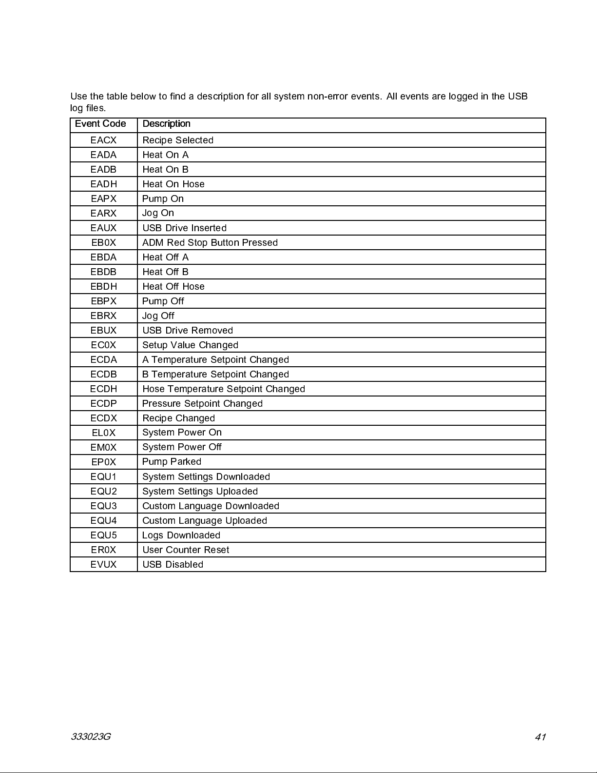
System Events
Use the table below to find a description for all system non-error events. All events are logged in the USB
log files.
Event Code Description
EACX
EADA
EADB
EADH
EAPX
EARX
EAUX
EB0X
EBDA
EBDB
EBDH
EBPX
EBRX
EBUX
EC0X
ECDA
ECDB
ECDH
ECDP
ECDX
EL0X
EM0X
EP0X
EQU1
EQU2
EQU3
EQU4
EQU5
ER0X
EVUX
Recipe Selected
Heat On A
Heat On B
Heat On Hose
Pump On
Jog On
USB Drive Inserted
ADM Red Stop Button Pressed
Heat Off A
Heat Off B
Heat Off Hose
Pump Off
Jog Off
USB Drive Removed
Setup Value Changed
A Temperature Setpoint Changed
B Temperature Setpoint Changed
Hose Temperature Setpoint Changed
Pressure Setpoint Changed
Recipe Changed
System Power On
System Power Off
Pump Parked
System Settings Downloaded
System Settings Uploaded
Custom Language Downloaded
Custom Language Uploaded
Logs Downloaded
User Counter Reset
USB Disabled
333023G
41
Page 42

Startup
Startup
desired, the level can be entered and tracked in
the ADM. See Advanced Setup Screens, page 34.
4.
Check generator fuel level.
To prevent serious injury, only operate Reactor
with all covers and shrouds in place.
NOTICE
Proper system setup, startup, and shutdown
procedures are critical to electrical equipment
reliability. The following procedures ensure steady
voltage. Failure to follow these procedures will
cause voltage fluctuations that can damage
electrical equipment and void the warranty.
1.
Check fluid inlet filter screens.
Before daily startup, ensure that the
fluid inlet screens are clean. See
Flush Inlet Strainer Screen, page 56
NOTICE
Running out of fuel will cause voltage
fluctuations that can damage electrical
equipment and void the warranty. Do not run
out of fuel.
5.
Confirm main power switch is OFF before starting
generator.
6. Ensure the main breaker on the generator is in
the off position.
7. Start the generator. Allow it to reach full operating
temperature.
2.
Check ISO lubrication reservoir.
Check level and condition of ISO lube daily. See
Pump Lubrication System, page 57.
3. Use A and B Drum Level Sticks (24M174) to
measure the material level in each drum.. If
42
8.
Turn main power switch ON.
The ADM will display the following screen until
communication and initialization is complete.
333023G
Page 43
Startup
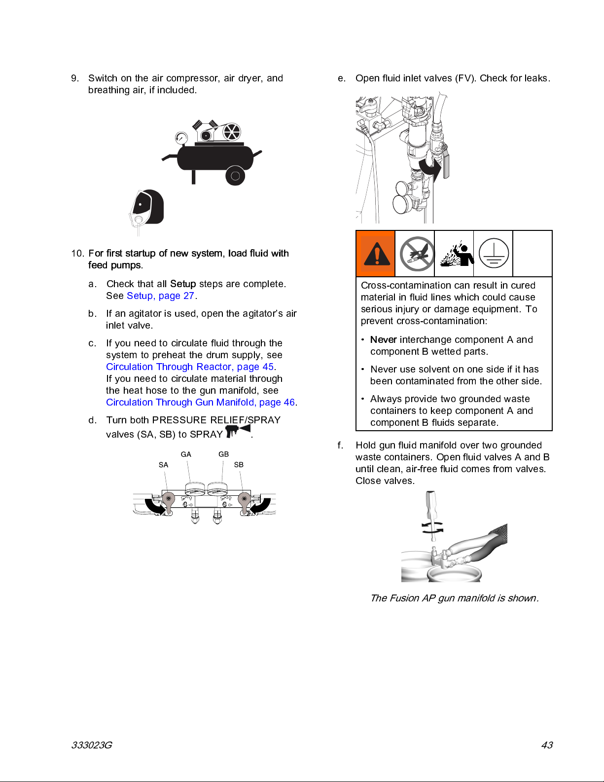
9. Switch on the air compressor, air dryer, and
breathing air, if included.
10.
For first startup of new system, load fluid with
feed pumps.
a. Check that all
See Setup, page 27.
b. If an agitator is used, open the agitator’s air
inlet valve.
c. If you need to circulate fluid through the
system to preheat the drum supply, see
Circulation Through Reactor, page 45.
If you need to circulate material through
the heat hose to the gun manifold, see
Circulation Through Gun Manifold, page 46.
d. Turn both PRESSURE RELIEF/SPRAY
valves (SA, SB) to SPRAY
Setup
steps are complete.
.
e. Open fluid inlet valves (FV). Check for leaks.
Cross-contamination can result in cured
material in fluid lines which could cause
serious injury or damage equipment. To
prevent cross-contamination:
•
Never
interchange component A and
component B wetted parts.
• Never use solvent on one side if it has
been contaminated from the other side.
• Always provide two grounded waste
containers to keep component A and
component B fluids separate.
f. Hold gun fluid manifold over two grounded
waste containers. Open fluid valves A and B
until clean, air-free fluid comes from valves.
Close valves.
The Fusion AP gun manifold is shown.
333023G 43
Page 44

Startup
11. Press to activate ADM.
12. If necessary, setup the ADM in Setup Mode. See
Advanced Display Module (ADM) Operation,
page 31.
13. Preheat t he system:
a. Press
to turn on hose heat zone.
Thermal expansion can cause
overpressurization, resulting in equipment
rupture and serious injury, including fluid
injection. Do not pressurize system when
preheating hose.
b. If you need to circulate fluid through the
system to preheat the drum supply, see
Circulation Through Reactor, page 45.
If you need to circulate material through
theheathosetothegunmanifold,see
Circulation Through Gun Manifold, page 46.
c. Wait for the hose to reach set point
temperature.
This equipment is used with heated fluid
which can cause equipment surfaces to
become very hot. To avoid severe burns:
• Do not touc h hot fluid or equipment.
• Do not turn on hose heat without fluid
in hoses.
• Allow equipment to cool completely
before touching it.
• Wear gloves if fluid temperature exceeds
110°F (43°C).
d. Press
Note
Hose heat-up time may increase at
voltages less than nominal 230 VAC
when maximum hose length is used.
to turn on A and B heat zones.
44
333023G
Page 45

Fluid Circulation
Fluid Circulation
Circulation Through Reactor
NOTICE
To prevent equipment damage, do not circulate
fluid containing a blowing agent without consulting
with your material supplier rega rding fluid
temperature limits.
NOTE:
fluid flow rates with temperature set points at desired
drum temperature. Low temperature rise deviation
errors may result.
To circulate through gun manifold and preheat hose,
see Circulation Through Gun Manifold, page 46.
1. Follow Startup, page 42.
Optimum heat transfer is achieved at lower
To avoid injection injury and splashing, do not
install shutoffs downstream of the PRESSURE
RELIEF/SPRAY valve outlets (BA, BB). The
valves function as overpressure relief valves
when set to SPRAY
open so valves can automatically relieve
pressure when machine is operating.
.Linesmustbe
3. Set PRESSURE RELIEF/SPRAY valves (SA,
SB) to PRESSURE RELIEF/CIRCULATION
4. Set temperature targets. See Targets, page 37.
5. Press
A and B temperatures reach targets. See
Jog Mode, page 46 for more information about
jog mode.
6. Press
7. Turn on the A and B heat zones. Wait until the
fluid inlet valve temperature gauges (FV) reach
the minimum chemical temperature from the
supply drums.
8. Exit jog mode.
9. Set PRESSURE RELIEF/SPRAY valves (SA,
SB) to SPRAY
to circulate fluid in jog mode until
to turn on the hose heat zone.
.
.
2. See Typical Installation, with system fluid
manifold to drum circulation, page 14.Route
circulation lines back to respective component
A or B supply drum. Use hoses rated at the
maximum working pressure of this equipment.
See Technical Specifications, page 66.
333023G 45
Page 46

Jog Mode
Circulation Through Gun Manifold
NOTICE
To prevent equipment damage, do not circulate
fluid containing a blowing agent without consulting
with your material supplier regarding fluid
temperature limits.
NOTE:
fluid flow rates with temperature set points at desired
drum temperature. Low temperature rise deviation
errors may result.
Circulating fluid through the gun manifold allows
rapid preheating of the hose.
1. Install gun fluid manifold (P) on accessory
Optimum heat transfer is achieved at lower
circulation kit (CK). Connect high press u re
circulation lines (R) to circulation manifold.
hoses rated at the maximum working
pressure of this equipment. See
Technical Specifications, page 66.
3. Follow procedures from Startup, page 42.
4. Turn main power switch on
5. Set temperature targets. See Targe ts, page 37.
6. Press
A and B temperatures reach targets. See
Jog Mode, page 46 for more information about
jog mode.
to circulate fluid in jog mode until
.
Jog Mode
Jogmodehastwopurposes:
• It can speed fluid heating during circulation.
• It can ease system flushing and priming.
The Fusion AP gun manifold is shown.
CK Gun
246362 Fusion AP 309818
256566
2. Route circu lat ion lines ba ck to respect iv e
component A or B supply drum. Use
Fusion CS
Manual
313058
1. Turn main power switch on
2. Press circulate
3. Press up or down
(J1 through J20).
Note
Jog speeds correlate to 3-30% of motor
power, but will not operate over 700 psi
(4.9 MPa, 49 bar) for either A or B.
4. Press
5. To stop the motor and exit jog mode press
or .
to start motor.
to enter jog mode.
to change jog speed
.
46 333023G
Page 47

Spraying
The Fusion AP gun is shown.
1. Engage gun piston safety lock and close gun
fluid inlet valves A and B.
Fusion Probler
2. Attach gun fluid manifold. Connect gun air line.
Open air line valve.
Spraying
6. Open fluid inlet valve located at each pump inlet.
7. Press to start motor and pumps.
3. Adjust the gun air regulator to desired gun air
pressure. Do not exceed the maximum rated
air pressure.
4. Set PRESSURE RELIEF/SPRAY valves (SA,
SB) to SPRAY
5. Verify heat zones are on and temperatures
and pressures are on target, see
Home screen, page 37.
.
8. Check fluid pressure gauges (GA, GB) to
ensure proper pressure balance. If imbalanced,
reduce pressure of hi gher component by
slightly
valve for that component toward PRESSURE
RELIEF/CIRCULATION
balanced pressures.
turning PRESSURE RELIEF/SPRAY
until gauges show
333023G
47
Page 48
Spraying
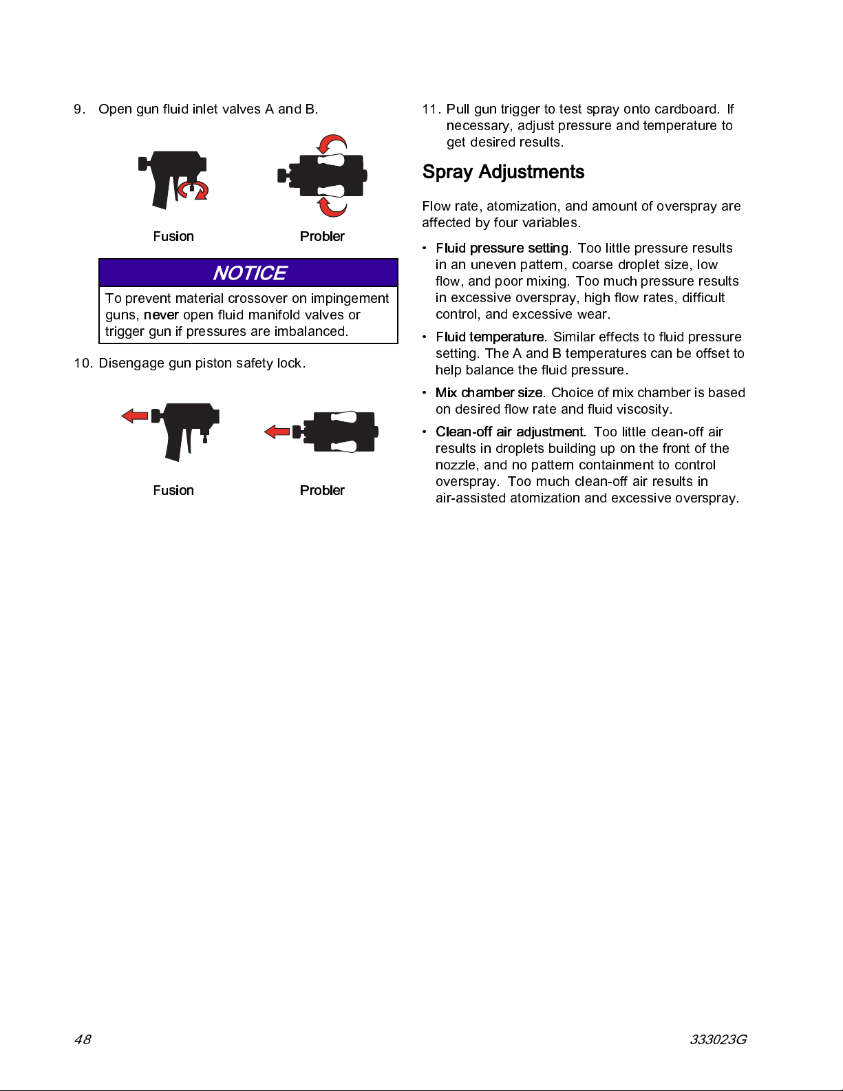
9. Open gun fluid inlet valves A and B.
Fusion Probler
NOTICE
To prevent material crossover on impinge ment
guns,
never
open fluid manifold valves or
trigger gun if pressures are imbalanced.
10. Disengage gun piston safety lock.
Fusion Probler
11. Pull gun trigger to test spray onto cardboard. If
necessary, adjust pressure and temperature to
get desired results.
Spray Adjustments
Flow rate, atomization, and amount of overspray are
affected by four variables.
•
Fluid pressure setting.
in an uneven pattern, coarse droplet size, low
flow, and poor mixing. Too much pressure results
in excessive overspray, high flow rates, difficult
control, and excessive wear.
•
Fluid temperature.
setting. The A and B temperatures can be offset to
help balance the fluid pressure.
•
Mix chamber size.
on desired flow rate and fluid viscosity.
•
Clean-off air adjustment.
resultsindropletsbuildinguponthefrontofthe
nozzle, and no pattern containment to control
overspray. Too much clean-off air results in
air-assisted atomization and excessive overspray.
Toolittlepressureresults
Similar effects to fluid pressure
Choice of mix chamber is based
Too little clean-off air
48 333023G
Page 49

Manual Hose Heat Mode
Manual Hose Heat Mode
If the system produces the T6DH sensor error hose
alarm or the T6DT sensor error TCM alarm, use
manual hose heat mode until the hose RTD cable or
FTS temperature sensor can be repaired.
Do not use Manual Hose Mode for extended periods
of time. The system performs best when the hose
has a valid RTD and can operate i n temperature
control mode. If a hose RTD breaks, the first priority
is to fix the RTD. Manual Hose Mode can help finish
a job while waiting for repair parts.
3. Select Enable Manual Hose Mode.
Note
When manual hose mode is enabled, the
manual hose mode advisory EVCH-V
will appear.
4. Enter Run Mode and navigate to the Target
screen. Use the up and down arrows to set the
desiredhosecurrent.
Enable Manual Hose Mode
1. Disconnect the hose RTD sensor from the TCM.
2. Enter Setup Mode and navigate to System
Screen 2.
Hose Current Settings Hose Current
Default
Maximum 37A
20A
333023G 49
Page 50
Manual Hose Heat Mode
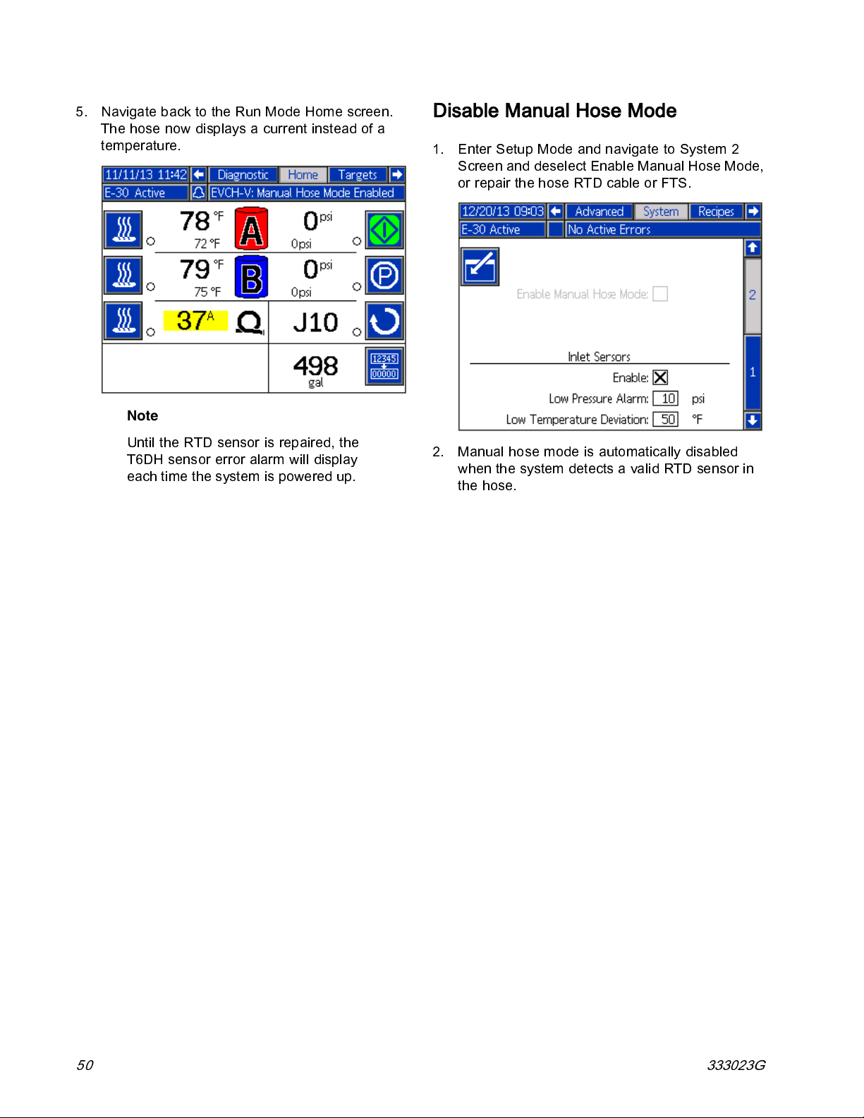
5. Navigate back to the Run Mode Home screen.
The hose now displays a current instead of a
temperature.
Note
Until the RTD sensor is repaired, the
T6DH sensor error alarm will display
each time the system is powered up.
Disable Manual Hose Mode
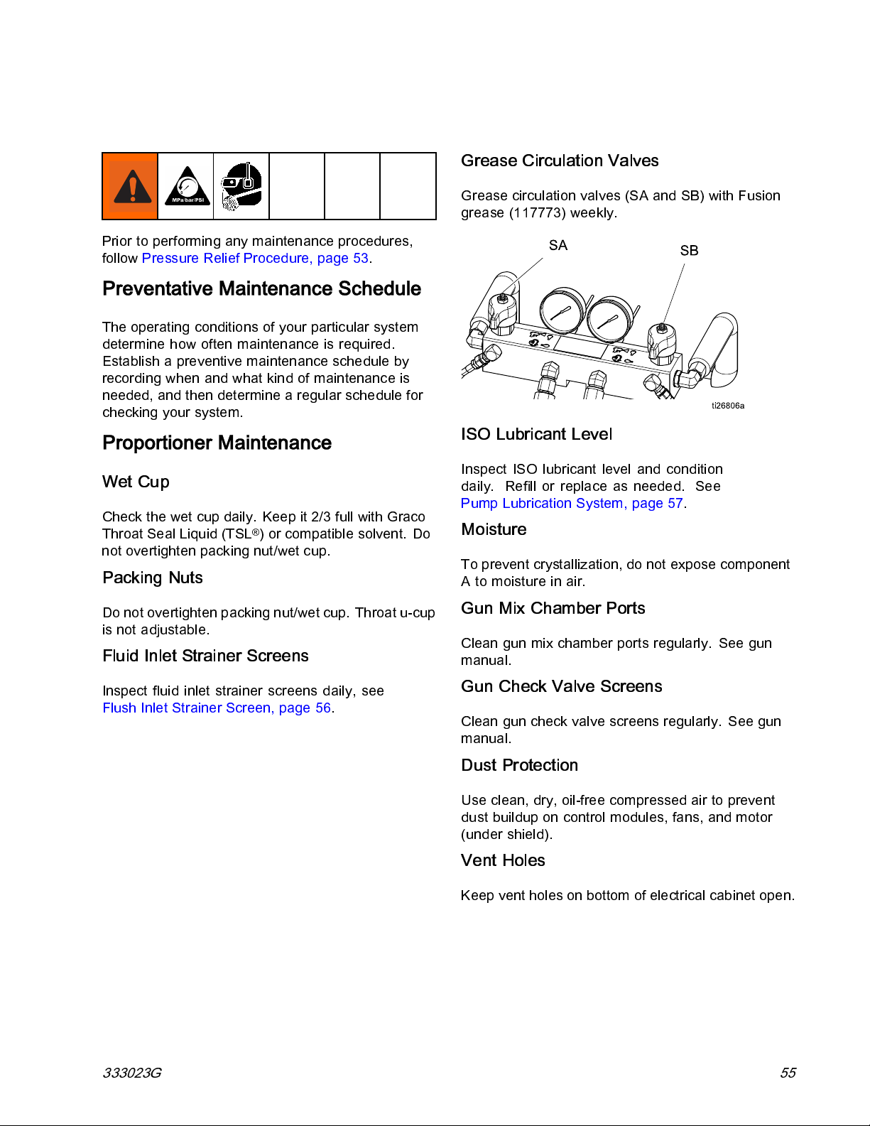
1. Enter Setup Mode and navigate to System 2
Screen and deselect Enable Manual Hose Mode,
or repair the hose RTD cable or FTS.
2. Manual hose mode is automatically disabled
when the system detects a valid RTD sensor in
the hose.
50 333023G
Page 51

Shutdown
Shutdown
NOTICE
Proper system setup, startup, and shutdow n
procedures are critical to electrical equipment
reliability. The following procedures ensure steady
voltage. Failure to follow these procedures will
cause voltage fluctuations that can damage
electrical equipment and void the warranty.
1. Press to stop the pumps.
2. Turn off all heat zones.
6. Turn off the air compressor, air dryer, and
breathing air.
7. Turn main power switch OFF.
3. Relieve pressu re. See
Pressure Relief Procedure, page 53.
4. Press to park the Component A Pump. The
park operation is complete when green dot goes
out. Verify the park operation is complete be fore
moving to next step.
5. Press to deactivate the system.
To prevent electric shock do not remove any
shrouds or open the electrical enclosure door.
8. Close all fluid supply valves.
333023G 51
Page 52

Shutdown
9. Set PRESSURE RELIEF/SPRAY valves (SA,
SB) to SPRAY
to seal out moisture from
drain line.
10. Engage gun piston safety lock then close fluid
inlet valves A and B.
Fusion Probler
52 333023G
Page 53

Pressure Relief Procedure
Pressure Relief Procedure
Follow the Pressure Relief Procedure
whenever you see this symbol.
This equipment stays pressurized until pressure
is manually relieved. To help prevent serious
injury from pressurized fluid, such as skin injection,
splashing fluid and moving parts, follow the
Pressure Relief Procedure when you stop spraying
and before cleaning, checking, or servicing
equipment.
The Fusion AP gun is shown.
1. Relieve pressure in gun and perform gun
shutdown procedure. See gun manual.
2. Engage gun piston safety lock.
3. Close gun fluid inlet valves A and B.
4. Shut off feed pumps and agitator, if used.
5. Route fluid to waste containers or supply tanks.
Turn PRESSURE RELIEF/SPRAY valves (SA,
SB) to PRESSURE RELIEF/CIRCULATION
. Ensure gauges drop to 0.
333023G 53
Page 54

Flushing
Flushing
To flush feed hoses, pumps, and heaters
separately from heated hoses, set PRESSURE
RELIEF/SPRAY valves (SA, SB) to PRESS URE
To help prevent fire and explosion:
• Flush equipment only in a well-ventilated area.
• Do not spray flammable fluids.
• Do not turn on heaters while flushing with
flammable solvents.
• Flush out o ld fluid with new fluid, or flush out old
fluid with a compatible solvent before introducing
new fluid.
• Use the lowest possible pressure when flushing.
• All wetted parts are compatible with common
solvents. Use only moisture-free solvents.
RELIEF/CIRCULATION
lines (N).
To flush entire system, circulate through gun fluid
manifold (with manifold removed from gun).
To prevent moisture from reacting with isocyanate,
always leave the system filled with a moisture-free
plasticizer or oil. Do not use water. Never leave the
system dry. See Important Isocyanate Information.
. Flush through bleed
54 333023G
Page 55
Maintenance
Prior to performing any maintenance procedures,
follow Pressure Relief Procedure, page 53.
Preventative Maintenance Schedule
The operating conditions of your particular system
determine how often maintenance is required.
Establish a preventive maintenance schedule by
recording when and what kind of maintenance is
needed, and then determine a regular schedule for
checking your system.
Proportioner Maintenance
Maintenance
Grease Circulation Valves
Grease circulation valves (SA and SB) with Fusion
grease (117773) weekly.
ISO Lubricant Level
Wet Cup
Check the wet cup daily. Keep it 2/3 full with Graco
Throat Seal Liquid (TSL
not overtighten packing nut/wet cup.
®
) or compatible solvent. Do
Packing Nuts
Do not overtighten packing nut/wet cup. Throat u-cup
is not adjustable.
Fluid Inlet Strainer Screens
Inspect fluid inlet strainer screens daily, see
Flush Inlet Strainer Screen, page 56.
Inspect ISO lubricant level and condition
daily. Refill or replace as needed. See
Pump Lubrication System, page 57.
Moisture
To prevent crystallization, do not expose component
Atomoistureinair.
Gun Mix Chamber Ports
Clean gun mix chamber ports regularly. See gun
manual.
Gun Check Valve Screens
Clean gun check valve screens regularl y. See gun
manual.
Dust Protection
Use clean, dry, oil-free compressed air t o prevent
dust buildup on control modules, fans, and motor
(under shield).
Vent Holes
Keep vent holes on bottom of electrical cabinet open.
333023G 55
Page 56

Maintenance
Flush Inlet Strainer Screen
The inlet strainers filter out particles that can plug the
pump inlet check valves. Inspect the screens daily as
part of the startup routine, and clean as required.
Isocyanate can crystallize from moisture
contamination or from freezing. If the chemicals used
are clean and proper storage, transfer, and operating
procedures are followed, there should be minimal
contamination of the A-side screen.
Note
Clean the A-side screen only during
daily startup. This minimizes moisture
contamination by immediately flushing
out any isocyanate residue at the start of
dispensing operations.
1. Close the fluid inlet valve at the pump inlet and
shut off the appropriate feed pump. This prevents
material from being pumped while cleaning the
screen.
compatible solvent and shake it dry. Inspect the
screen. No more than 25% of the mesh should
be restri ct ed. If more than 25% of the mesh is
blocked, replace the screen. Inspect the gasket
(B) and replace as required.
4. Ensure the pipe plug (D) is screwed into the
strainer plug (C). Install the strainer plug with the
screen(A)ando-ring(B)inplaceandtighten.Do
not overtighten. Let the gasket make the seal.
5. Open the fluid inlet valve, ensure that there are
no leaks, and wipe the equipment clean. Proceed
with operation.
2. Place a containerunderthe strainerbase to catch
drain off when removing the strainer plug (C).
3. Remove the screen (A) from the strainer
manifold. Thoroughly flush the screen with
Figure 15
56 333023G
Page 57

Maintenance
Pump Lubrication System
Check the condition of the ISO pump lubricant daily.
Change the lubricant if it becomes a gel, its color
darkens, or it becomes diluted with isocyanate.
Gel formation is due to moisture absorption by the
pump lubricant. The interval between changes
depends on the environment in which the equipment
is operating. The pump lubrication system minimizes
exposure to moisture, but some contamination is still
possible.
Lubricant discoloration is due to continual seepage of
small amounts of isocyanate past t he pump packings
during operation. If the packings are operating
properly, lubricant replacement due to discoloration
should not be necessary more often than every 3 or
4weeks.
To change pump lubricant:
1. Follow Pressure Relief Procedure, page 53.
2. Lift the lubricant reservoir (R) out of the bracket
and remove the container from the cap. Holding
the cap over a suitable container, remove the
check valve and allow the lubricant to drain.
Reattach the check valve to the inlet hose.
3. Drain the reservoir and flush it with clean
lubricant.
4. When the reservoir is flushed clean, fill with fresh
lubricant.
5. Thread the reservoir onto the cap assembly and
place it in the bracket.
6. The lubrication system is ready for operation. No
priming is required.
Pump Lubrication System
Figure 16
333023G 57
Page 58

Errors
Errors
View Errors
When an error occurs the error information screen
displays the active error code and description.
The error code, alarm bell, and active errors will scroll
in the status bar. For a list of the ten most recent
errors see Troubleshooting, page 59. Error codes
arestoredintheerrorloganddisplayedontheError
and Troubleshooting screens on the ADM.
There are
are indic
tower (op
Alarms are indicated by
a parameter critical to the process has reached a
level requiring the system to stop. The alarm needs
to be addressed immediately.
Deviations are indicated by
indicates a parameter critical to the process has
reached a level requiring attention, but not sufficient
enough to stop the system at this time.
Advi
cates a parameter that is not immediately critical
indi
to th
prev
three types of errors that can occur. Errors
ated on the display as well as by the light
tional).
. This condition indi cates
. This condition
sories are indicated by
e process. The advisory needs attention to
ent more serious issues in the future.
. This condition
Troubleshoot Errors
To troubleshoot the error:
1. Press the soft key next to “Help With This Error”
for help with the active error.
Note
Press or to return to the
previously displayed screen.
2. The QR c ode screen will be dis pl ay ed. Scan
the QR code with your smart phone to be sent
directly to online troubleshooting for the active
error code. Otherwise, manually navigate to
http://help.graco.com and search for the active
error.
To diagnose the active error, see
Troubleshoot Errors, page 58.
3. If no internet connection is available, see
Error Codes and Troubleshooting, page 59 for
causes and solutions for each error code.
58 333023G
Page 59
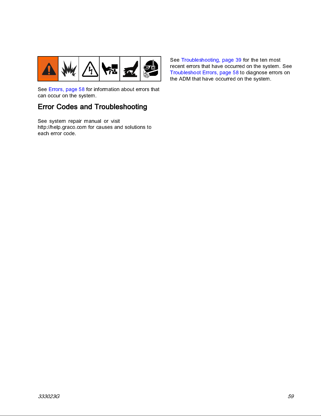
Troubleshooting
See Errors, page 58 for information about e rrors that
can occur on the system.
Error Codes and Troubleshooting
See system repair manual or visit
http://help.graco.com for causes and solutions to
each error code.
Troubleshooting
See Troubleshooting, page 39 for the ten most
recent errors that have occurred on the system. See
Troubleshoot Errors, page 58 to diagnose errors on
the ADM that have occurred on the system.
333023G 59
Page 60

USB Data
USB Data
Download Procedure
Note
System configuration setting files and custom
language files can be modified if the files
are in the UPLOAD folder of the USB flash
drive. See System Configuration Settings
File, Custom Language File, and Upload
Procedure sections.
1. Insert USB flash drive into USB port.
2. The menu bar and USB indi ca tor lights in dic ate
that the USB is downloading files. Wai t for USB
activity to complete.
3. Remove USB flash drive from USB port.
4. Insert USB flash drive into USB port of computer.
5. The USB flash drive window automatica lly opens.
If it does not, open USB flash drive from within
Windows® Explorer.
6. Open GRACO folder.
7. Instructions continue on next page.
8. Open the system folder. If downloading data
from more than one system, there will be more
than one folder. Each folder is labeled with the
corresponding serial number of the ADM (The
serial number is on the back of the ADM.)
9. Open DOWNLOAD folder.
10. Open DATAxxxx folder.
11. Open DATAxxxx folder labeled with the highest
number. The highest number indicates the most
recent data download.
12. Open log file. Log files open in Microsoft® Excel
by default as long as the program is installed.
However,theycanalsobeopenedinanytext
editor or Microsoft® Word.
Note
All USB logs are saved in Unicode
(UTF-16) format. If opening the log
file in Microsoft Word, select Unicode
encoding.
USB Logs
Note
The ADM can read/write to FAT (File
Allocation Table) storage devices. NTFS,
used by 32 GB or greater storage devices,
is not supported.
During operation, the ADM stores system and
performance related information to memory in the
form of log files. The ADM maintains six log files:
•EventLog
• Job Log
•DailyLog
• System Software Log
• Blackbox Log
• Diagnostics Log
Follow Download Procedure, page 60,toretrieve
log files.
Each time a USB flash drive is inserted into the ADM
USB port, a new folder named DATAxxxx is created.
The number at the end of the folder name increases
each time a USB flash drive is inserted and data is
downloaded or uploaded.
Event Log
The event log file name is 1–EVENT.CSV and is
stored in the DATAxxxx folder.
The event log maintains a record of the last 49,000
events and errors. Each event record contains:
• Date of event code
• Time of event code
• Event code
•Eventtype
• Action taken
• Event Description
Event codes include both error codes (alarms,
deviations, and advisories) and record only events.
Actions Taken includes setting and clearing event
conditions by the system, and acknowledging error
conditions by the user.
60 333023G
Page 61

USB Data
Job Log
Thejoblogfilenameis2–JOB.CSVandisstored
in the DATAxxxx folder.
The job log maintains a record of data points
based on the USB Log Frequency defined
in the Setup screens. The ADM stores the
last 237,000 da ta points f or d ownloa d. See
Setup - Advanced Screen 3 — USB, page 34,for
informationonsettingtheDownloadDepthandUSB
Log Frequency.
• Data point date
• Data point time
• A side temperature
• B side temperature
• Hose temperature
• A side temperature setpoint
• B side temperature setpoint
• Hose temperature setpoint
• A side inlet pressure
• B side inlet pressure
• Inlet pressure setpoint
System Software Log
The system software file name is 4–SYSTEM.CSV
andisstoredintheDATAxxxxfolder.
The system software log lists the following:
• Date log was created
• Time log was created
• Component name
• Software version loaded on the above component
Blackbox Log File
The black box file name is 5–BLACKB.CSV and is
stored in the DATAxxxx folder.
The Blackbox log maintains a record of how the
system runs and the features that are used. This log
will help Graco troubleshoot system errors.
Diagnostics Log File
Thediagnosticsfilenameis6–DIAGNO.CSVandis
stored in the DATAxxxx folder.
The Diagnostics log maintains a record of how the
system runs and the features that are used. This log
will help Graco troubleshoot system errors.
• System lifetime pump cycle counts
• Pressure, volume, and temperature units
• Job name/number
Daily Log
The daily log file name is 3–DAILY.CSV and is stored
in the DATAxxxx folder.
The daily log maintains a record of the total cycle
and volume sprayed on any day that the system is
powered up. The volume units will be the same units
that were used in the Job Log.
The following data is stored in this file:
• Date that material was sprayed
• Time—unusedcolumn
• Total pump cycle count for day
• Total volume sprayed for day
System Configuration Settings
The system configuration settings file name is
SETTINGS.TXT and is stored in the DOWNLOAD
folder.
A system configuration settings file automatically
downloads each time a USB flash drive is inserted
into the ADM. Use this file to back up system
settings for future recovery or to easily replicate
settings across multiple systems. Refer to the
Upload Procedure, page 62 for instructions on how
to use this file.
333023G 61
Page 62

USB Data
Custom Language File
The custom language file name is DISPTEXT.TXT
andisstoredintheDOWNLOADfolder.
A custom language file automatically downloads
each time a USB flash drive is inserted into the ADM.
If desired, use this file to create a user-defined set of
custom language strings to be displayed within the
ADM.
The system is able to display the following Unicode
characters. For characters outside of this set,
the system will display the Unicode replacement
character, which appears as a white question mark
inside of a black diamond.
• U+0020 - U+007E (B asic Latin)
• U+00A1 - U+00FF (Latin-1 Supplement)
• U+0100 - U+017F (Latin Extended-A)
• U+0386 - U+03CE (Greek)
• U+0400 - U+045F (Cyrillic)
Create Custom Language Strings
The custom language file is a tab-delimited text file
that contains two columns. The first column consists
of a list of strings in the language selected at the
time of download. The second column can be used
to enter the custom language strings. If a custom
language was previously installed, this column
contains the custom strings. Otherwise the second
column is blank.
Modify the second column of the custom language file
as needed and the follow Upload Procedure, page 62 ,
to install the file.
The format of the custom language file is critical.
The following rules must be followed in order for the
installation process to succeed.
• Define a custom string for each row in the second
column.
Note
• The fil e format must be a tab-delimited text file
using Unicode (UTF-16) character representation.
• The file must contain only two columns, with
columns separated by a single tab character.
• Do not add or remove rows to the file.
• Do not change the order of the rows.
Upload Procedure
Use this procedure to install a system configuration
file and/or a custom language file.
1. If necessary, follow the
automatically generate the proper folder structure
on the USB flash drive.
2. Insert USB flash drive into USB port of computer.
3. The USB flash drive window automatically opens.
If it does not, open USB flash drive from within
Windows Explorer.
4. Open GRACO folder.
5. Open the system folder. If working with more
than one system, there will be more than one
folder within the GRACO folder. Each folder is
labeled with the corresponding serial number of
theADM.(Theserialnumberisonthebackof
the module.)
6. If installing the system configuration settings
file, place SETTINGS.TXT file into the UPLOAD
folder.
7. If installing the custom language file, place
DISPTEXT.TXT file into the UPLOAD folder.
8. Remove USB flash drive from the computer.
9. Install USB flash drive into the ADM USB port.
10. The menu bar and USB indicator lights indicate
that the USB is downloading files. Wait for USB
activity to complete.
11. Remove USB flash drive from USB port.
Note
Download Procedure
to
If the custom language file is used, you
must define a custom string for each
entry in the DISPTEXT.TXT file. Blank
second-column fields will be displayed
blank on the ADM.
• The file name must be DISPTEXT.TXT.
62 333023G
If the custom language file was installed,
users can now select the new language
from the Language drop-down menu in
Advanced Screen 1 — General, page 34.
Page 63

Performance Charts
Performance Charts
Use these charts to help identify the proportioner that will work most efficiently with each mix chamber. Flow
rates are based on a material viscosity of 60 cps.
NOTICE
To prevent system damage, do not pressurize the
system above the line for the gun tip size being used.
Proportioners For Foam
2000
(138)
AR4242
(01)
PRESSURE
psi (bar)
150 0
(103)
100 0
(69)
500
(34)
05
(2.3)
AR5252
(02)
10
(4.5)
15
(6.8)
(9.1)
20
FLOW lbs/min (kg/min)
AR6060
(03)
AR7070
(04)
25
(11.3)
E-30
30
(13.6)
35
(15.9)
40
(18.1)
333023G 63
Page 64
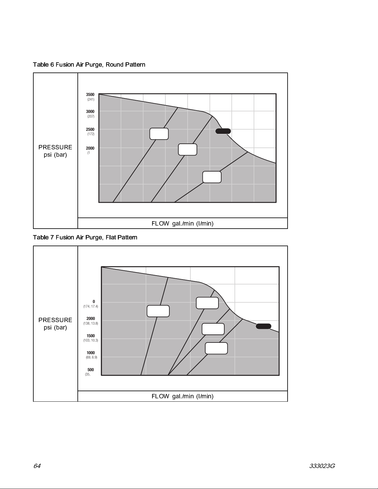
Performance Charts
Proportioners For Coatings
Table 6 Fusion Air Purge, Round Pattern
3500
(241)
3000
(207)
2500
(172)
PRESSURE
psi (bar)
2000
(138)
150 0
(103)
100 0
(69)
500
(34)
0 0.5
Table 7 Fusion Air Purge, Flat Pattern
3500
(241, 24.1)
3000
(207, 20.7)
2500
(174, 17.4)
PRESSURE
2000
(138, 13.8)
psi (bar)
1500
(103, 10.3)
1000
(69, 6.9)
AR2020
(000)
AR2929
(00)
(1.9)
1.0
(3.8)
FLOW gal./min (l/min)
AF2020
(FTXX24 TIP)
AR4242
(01)
AF2929
(FTXX38 TIP)
AF4242
(FTXX38 TIP)
AF5252
(FTXX48 TIP)
E-XP2
1.5
(5.7)
E-XP2
2.0
(7.6)
500
(35, 3.5)
0 0.5
(1.9)
1.0
(3.8)
1.5
(5.7)
2.0
(7.6)
FLOW gal./min (l/min)
64 333023G
Page 65

Table 8 Fusion Mechanical Purge, Round Pattern
3500
(241, 24.1)
3000
PRESSURE
(207, 20.7)
2500
(174, 17.4)
2000
(138, 13.8)
XR2323
(RTM040)
psi (bar)
1500
(103, 10.3)
1000
(69, 6.9)
500
(35, 3.5)
0 0.5
(1.9)
(RTM040)
XR3535
(RTM055)
E-XP2
XR2929
1
(3.8)
MR3535
(RTM040)
XR4747
(RTM055)
MR4747
(RTM055)
1.5
(5.7)
Performance Charts
2.0
(7.6)
FLOW gal./min (l/min)
Table 9 Fusion Mechanical Purge, Flat Pattern
3500
(241, 24.1)
(1.5)
XF2323
(FTM424)
MF2929
(FTM424)
XF2929
(FTM424)
(FTM638)
0.6
(2.3)
XF3535
PRESSURE
psi (bar)
3000
(207, 20.7)
2500
(174, 17.4)
2000
(138, 13.8)
1500
(103, 10.3)
1000
(69, 6.9)
500
(35, 3.5)
0 0.4
XF1313
(FTM424)
(FTM424)
XF1818
(FTM424)
0.2
(0.7)
MF1818
FLOW gal./min (l/min)
MF3535
(FTM638)
0.8
(3.0)
(3.8)
1
MF4747
(FTM638)
XF5757
(FTM638)
MF5757
(FTM638)
1.2
(4.5)
1.4
(5.3)
1.6
(6.0)
E-XP2
1.8
(6.8)
2.0
(7.6)
333023G 65
Page 66
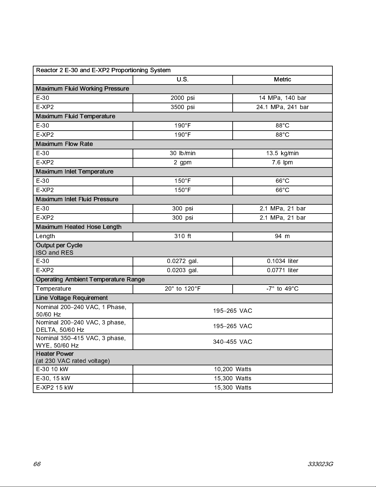
Technical Specifications
Technical Specifications
Reactor 2 E-30 and E-XP2 Proportioning System
U.S.
Maximum Fluid Working Pressure
E-30 2000 psi 14 MPa, 140 bar
E-XP2 3500 psi 24.1 MPa, 241 bar
Maximum Fluid Temperature
E-30
E-XP2
Maximum Flow Rate
E-30 30 lb/min 13.5 kg/min
E-XP2 2 gpm 7.6 lpm
Maximum Inlet Temperature
E-30
E-XP2
Maximum Inlet Fluid Pressure
E-30 300 psi 2.1 MP a, 21 bar
E-XP2 300 psi 2.1 MPa, 21 bar
Maximum Heated Hose Length
Length
Output per Cycle
ISO and RES
E-30 0.0272 gal. 0.1034 liter
E-XP2 0.0203 gal. 0.0771 liter
Operating Ambient Temperature Range
Temperature
Line Voltage Requirement
Nominal 200–240 VAC, 1 Phase,
50/60 Hz
Nominal 200–240 VAC, 3 phase,
DELTA, 50/60 Hz
Nominal 350–415 VAC, 3 phase,
WYE, 50/60 Hz
Heater Power
(at 2 30 VAC rated voltage)
E-30 10 kW 10,200 Watts
E-30, 15 kW 15,300 Watts
E-XP2 15 kW 15,300 Watts
190°F 88°C
190°F 88°C
150°F 66°C
150°F 66°C
310 ft
20° to 120°F -7° to 49°C
195–265 VAC
195–265 VAC
340–455 VAC
Metric
94 m
66 333023G
Page 67
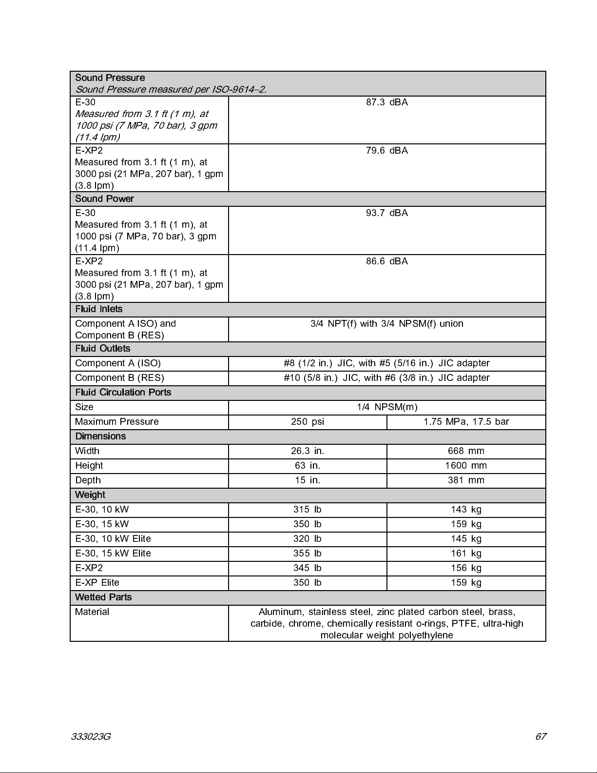
Technical Specifications
Sound Pressure
Sound Pressure measured per ISO-9614–2.
E-30
Measured from 3.1 ft (1 m), at
1000 psi (7 MPa, 70 bar), 3 gpm
(11.4 lpm)
E-XP2
Measured from 3.1 ft (1 m), at
3000 psi (21 MPa, 207 bar), 1 gpm
(3.8 lpm)
Sound Power
E-30
Measured from 3.1 ft (1 m), at
1000 psi (7 MPa, 70 bar), 3 gpm
(11.4 lpm)
E-XP2
Measured from 3.1 ft (1 m), at
3000 psi (21 MPa, 207 bar), 1 gpm
(3.8 lpm)
Fluid Inlets
Component A ISO) and
Component B (RES)
Fluid Outlets
Component A (ISO) #8 (1/2 in.) JIC, with #5 (5/16 in.) JIC adapter
Component B (RES) #10 (5/8 in.) JIC, with #6 (3/8 in.) JIC adapter
Fluid Circulation Ports
Size 1/4 NPSM(m)
Maximum Pressure 250 psi 1.75 MPa, 17.5 bar
Dimensions
Width 26.3 in. 668 mm
Height 63 in. 1600 mm
Depth 15 in. 381 mm
Weight
E-30, 10 kW 315 lb 143 kg
E-30, 15 kW 350 lb 159 kg
E-30, 10 kW Elite 320 lb 145 kg
E-30, 15 kW Elite 355 lb 161 kg
E-XP2 345 lb 156 kg
E-XP Elite 350 lb 159 kg
Wetted Parts
Material Aluminum, stainless steel, zinc plated carbon steel, brass,
carbide, chrome, chemically resistant o-rings, PTFE, ultra-high
3/4 NPT(f) with 3/4 NPSM(f) union
molecular weight polyethylene
87.3 dBA
79.6 dBA
93.7 dBA
86.6 dBA
333023G 67
Page 68

Notes
Notes
68 333023G
Page 69

Graco Extended Warranty for Reactor®2 Components
Graco warrants all equipment referenced in this document which is manufactured by Graco and bearing its
name to be free from defects in material and workmanship on the date of sale to the original purchaser for use.
With the exception of any special, extended, or limited warranty published by Graco, Graco will, for a period of
twelve months from the date of sale, repair or replace any part of the equipment determined by Graco to be
defective. This warranty applies only when the equipment is installed, operated and maintained in accordance
with Graco’s written recommendations.
Graco Part Number
24U050 Electric Motor
24U051 Electric Motor
24U831
24U832
24U855
24U854 Advanced Display Module
All other Reactor 2 parts 12 Months
This warranty does not cover, and Graco shall not be liable for general wear and tear, or any malfunction,
damage or wear caused by faulty installation, misapplication, abrasion, corrosion, inadequate or improper
maintenance, negligence, accident, tampering, or substitution of non-Graco component parts. Nor shall Graco
be liable for malfunction, damage or wear caused by the incompatibility of Graco equipment with structures,
accessories, equipment or materials not supplied by Graco, or the improper design, manufacture, installation,
operation or maintenance of structures, accessories, equipment or materials not supplied by Graco.
This warranty is conditioned upon the prepaid return of the equipment claimed to be defective to an authorized
Graco distributor for verification of the claimed defect. If the claimed defect is verified, Graco will repair or replace
free of charge any defective parts. The equipment will be returned to the original purchaser transportation
prepaid. If inspection of the equipment does not disclose any defect in material or workmanship, repairs will be
made at a reasonable charge, which charges may include the costs of parts, labor, and transportation.
THIS WARRANTY IS EXCLUSIVE, AND IS IN LIEU OF ANY OTHER WARRANTIES, EXPRESS OR IMPLIED,
INCLUDING BUT NOT LIMITED TO WARRANTY OF MERCHANTABILITY OR WARRANTY OF FITNESS
FORAPARTICULARPURPOSE.
Graco’s sole obligation and buyer’s sole remedy for any breach of warranty shall be as set forth above. The
buyer agrees that no other remedy (including, but not limited to, incidental or consequential damages for lost
profits, lost sales, injury to person or property, or any other incidental or consequential loss) shall be available.
Any action for breach of warranty hereunder must be brought within the latter of two (2) years of the date of
sale, or one (1) year the warranty period expires.
GRACO MAKES NO WARRANTY, AND DISCLAIMS ALL IMPLIED WARRANTIES OF MERCHANTABILITY
AND FITNESS FOR A PARTICULAR PURPOSE, IN CONNECTION WITH ACCESSORIES, EQUIPMENT,
MATERIALS OR COMPONENTS SOLD BUT NOT MANUFACTURED BY GRACO.
manufactured by Graco (such as electric motors, switches, hose, etc.), are subject to the warranty, if any, of
their manufacturer. Graco will provide purchaser with reasonable assistance in making any claim for breach of
these warranties.
In no event will Graco be liable for indirect, incidental, special or consequential damages resulting from Graco
supplying equipment hereunder, or the furnishing, performance, or use of any products or other goods sold
hereto, whether due to a breach of contract, breach of warranty, the negligence of Graco, or otherwise.
FOR GRACO CANADA CUSTOMERS
The Parties acknowledge that they have required that the present document, as well as all documents, notices
and legal proceedings entered into, given or instituted pursuant hereto or relating directly or indirectly hereto, be
drawn up in English. Les parties reconnaissent avoir convenu que la rédaction du présente document sera en
Anglais, ainsi que tous documents, avis et procédures judiciaires exécutés, donnés ou intentés, à la suite de ou
en rapport, directement ou indirectement, avec les procédures concernées.
Description Warranty Period
36 Months or 3 Million Cycles
36 Months or 3 Million Cycles
Motor Control Module 36 Months or 3 Million Cycles
Motor Control Module 36 Months or 3 Million Cycles
Heater Control Module 36 Months or 3 Million Cycles
36 Months or 3 Million Cycles
These items sold, but not
Page 70

Graco Information
For the latest information about Graco products, visit www.graco.com.
To place an order,
Phone:
612-623-6921
All written and visual data contained in this document reflects the latest product information available at the time of publication.
GRACO INC. AND SUBSIDIARIES • P.O. BOX 1441 • MINNEAPOLIS MN 55440-1441 • USA
contact your Graco Distributor or call to identify the nearest distributor.
or Toll Free:
Graco reserves the right to make c hanges at any time without notice.
Original Instructions. This manual contains English. MM 333023
Copyright 2014, Graco Inc. All Graco manufacturing locations are registered to ISO 9001.
1-800-328-0211
For patent information, see www.graco.com/patents.
Graco Headquarters:
International Offices:
Revision G, June 2015
Fax:
612-378-3505
Minneapolis
Belgium, China, Japan, Korea
www.graco.com
 Loading...