

Graco 231161, 224629, 231158, 231162, Ratio Monark Hydra-Spray Series Instructions-parts List Manual
Page 1
Instructions – Parts List
Parts
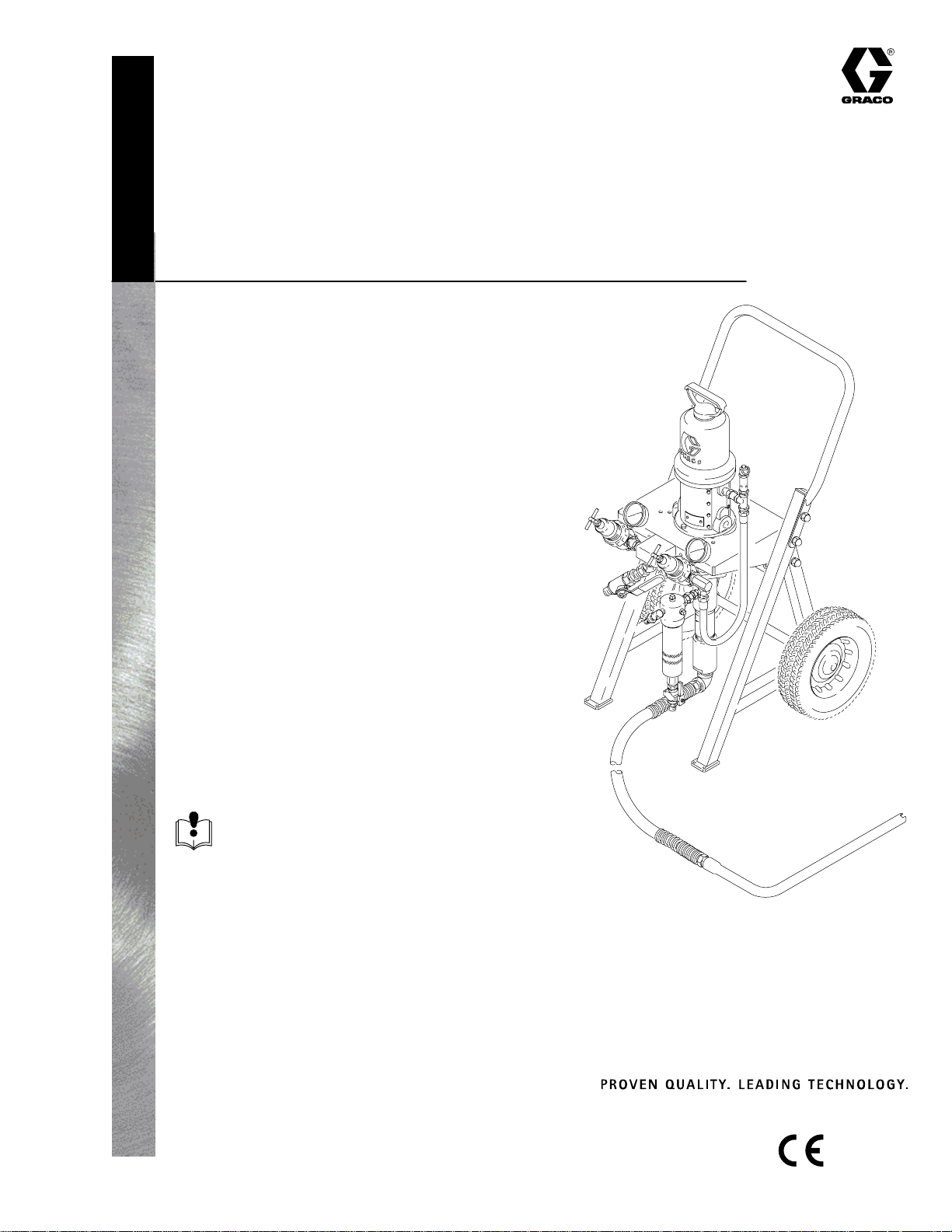
PORTABLE, AIR-ASSISTED AIRLESS
10:1 Ratio Monark
Hydra-Spray Pumps
95 psi (0.66 MPa, 6.6 bar) MAXIMUM AIR INLET PRESSURE
950 psi (6.6 MPa, 66 bar) MAXIMUM FLUID WORKING PRESSURE
Model 231158
For cold spray applications. Includes pump, cart, hose, gun and tip
Model 231162, Series B
For cold spray applications. Includes pump, cart,
fluid regulation kit 222564, hose, gun and tip
Model 224629, Series A
For heated spray applications. Includes pump, cart,
Viscon heater, heater mounting kit 222262,
and circulating kit 222436
Model 231161
For heated spray applications. Includes pump, cart,
Viscon heater, heater mounting kit 222262,
circulating kit 222436, hose, gun and tip
307929J
Read warnings and instructions.
See page 2 for table of contents.
Model 231158 Shown
GRACO INC.ąP.O. BOX 1441ąMINNEAPOLIS, MNą55440-1441
Copyright 1988, Graco Inc. is registered to I.S. EN ISO 9001
Page 2
Table of Contents
Symbols
Warnings 2–4. . . . . . . . . . . . . . . . . . . . . . . . . . . . . . . . . . . .
Installation 5–13. . . . . . . . . . . . . . . . . . . . . . . . . . . . . . . . . .
Operation 14–15. . . . . . . . . . . . . . . . . . . . . . . . . . . . . . . .
Parts Drawings and Lists 16–21. . . . . . . . . . . . . . . . . . .
Conversion Kits 23. . . . . . . . . . . . . . . . . . . . . . . . . . . . . . .
Technical Data 23. . . . . . . . . . . . . . . . . . . . . . . . . . . . . . . .
Warranty 24. . . . . . . . . . . . . . . . . . . . . . . . . . . . . . . . . . . . .
Graco Information 24. . . . . . . . . . . . . . . . . . . . . . . . . . . . .
WARNING
EQUIPMENT MISUSE HAZARD
Equipment misuse can cause the equipment to rupture or malfunction and result in serious injury.
INSTRUCTIONS
This equipment is for professional use only.
Warning Symbol
WARNING
This symbol alerts you to the possibility of serious
injury or death if you do not follow the instructions.
Caution Symbol
CAUTION
This symbol alerts you to the possibility of damage to
or destruction of equipment if you do not follow the
corresponding instructions.
Read all instruction manuals, tags, and labels before operating the equipment.
Use the equipment only for its intended purpose. If you are uncertain about usage, call your Graco
distributor.
Do not alter or modify this equipment. Use only genuine Graco parts and accessories.
Check equipment daily. Repair or replace worn or damaged parts immediately.
Do not exceed the maximum working pressure of the lowest rated system component. Refer to the
Technical Data on page 23 for the maximum working pressure of this equipment.
Use fluids and solvents which are compatible with the equipment wetted parts. Refer to the Tech-
nical Data section of all equipment manuals. Read the fluid and solvent manufacturer’s warnings.
Do not exceed the maximum working pressure of the lowest rated system component. This equip-
ment has a 950 psi (6.6 MPa, 66 bar) maximum working pressure.
Do not use hoses to pull equipment.
Route hoses away from traffic areas, sharp edges, moving parts, and hot surfaces. Do not expose
Graco hoses to temperatures above 82C (180F) or below –40C (–40F).
Wear hearing protection when operating this equipment.
Do not lift pressurized equipment.
2 307929
Comply with all applicable local, state, and national fire, electrical, and safety regulations.
Page 3
WARNING
INJECTION HAZARD
Spray from the gun, hose leaks, or ruptured components can inject fluid into your body and cause
extremely serious injury, including the need for amputation. Fluid splashed in the eyes or on the skin
can also cause serious injury.
Fluid injected into the skin might look like just a cut, but it is a serious injury. Get immediate medi-
cal attention.
Do not point the gun at anyone or at any part of the body.
Do not put your hand or fingers over the spray tip.
Do not stop or deflect leaks with your hand, body, glove or rag.
Do not “blow back” fluid; this is not an air spray system.
Always have the tip guard and the trigger guard on the gun when spraying.
Check the gun diffuser operation weekly. Refer to the gun manual.
Be sure the gun trigger safety operates before spraying.
Lock the gun trigger safety when you stop spraying.
Follow the Pressure Relief Procedure on page 14 whenever you: are instructed to relieve pres-
sure; stop spraying; clean, check, or service the equipment; and install or clean the spray tip.
Tighten all fluid connections before operating the equipment.
Check the hoses, tubes, and couplings daily. Replace worn, damaged, or loose parts immediately.
Permanently coupled hoses cannot be repaired; replace the entire hose.
Use only Graco approved hoses. Do not remove any spring guard that is used to help protect the
hose from rupture caused by kinks or bends near the couplings.
MOVING PARTS HAZARD
Moving parts, such as the air motor piston, can pinch or amputate your fingers.
Keep clear of all moving parts when starting or operating the pump.
Before servicing the equipment, follow the Pressure Relief Procedure on page 14 to prevent the
equipment from starting unexpectedly.
3307929
Page 4
WARNING
FIRE AND EXPLOSION HAZARD
Improper grounding, poor ventilation, open flames or sparks can cause a hazardous condition and
result in a fire or explosion and serious injury.
Ground the equipment and the object being sprayed. Refer to Grounding on page 5.
If there is any static sparking or you feel an electric shock while using this equipment, stop spray-
ing immediately. Do not use the equipment until you identify and correct the problem.
Provide fresh air ventilation to avoid the buildup of flammable fumes from solvents or the fluid
being sprayed.
Keep the spray area free of debris, including solvent, rags, and gasoline.
Electrically disconnect all equipment in the spray area.
Extinguish all open flames or pilot lights in the spray area.
Do not smoke in the spray area.
Do not turn on or off any light switch in the spray area while operating or if fumes are present.
Do not operate a gasoline engine in the spray area.
TOXIC FLUID HAZARD
Hazardous fluid or toxic fumes can cause serious injury or death if splashed in the eyes or on the skin,
inhaled, or swallowed.
Know the specific hazards of the fluid you are using.
Store hazardous fluid in an approved container. Dispose of hazardous fluid according to all local,
state and national guidelines.
Always wear protective eyewear, gloves, clothing and respirator as recommended by the fluid and
solvent manufacturer.
4 307929
Page 5
Installation
General
Be sure that all operators read and understand this
entire manual and the separate manuals supplied with
components and accessories before using this equipment.
Reference numbers and letters in parentheses refer to
the illustrations and the parts lists on pages 16–23.
Accessories mentioned in the text are available from
your Graco distributor. If you supply your own accessories, be sure they are adequately sized to meet your
system’s requirements.
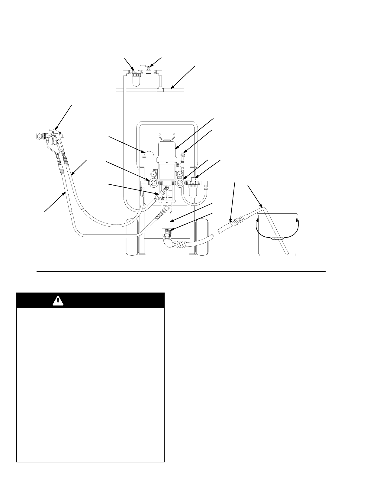
The Typical Installation shown in Fig. 2 is only an
example. For assistance in designing a system to meet
your particular needs, contact your Graco distributor.
System Accessories
Refer to Fig. 2. Install an air line filter (A) in the main
air line (B), to remove harmful dirt and moisture from
the compressed air supply. To provide automatic
lubrication of the air motor, install an air line lubricator
(C) downstream from the pump air regulator (31).
Install a second bleed valve (G) in the main air line, to
isolate the accessories for servicing.
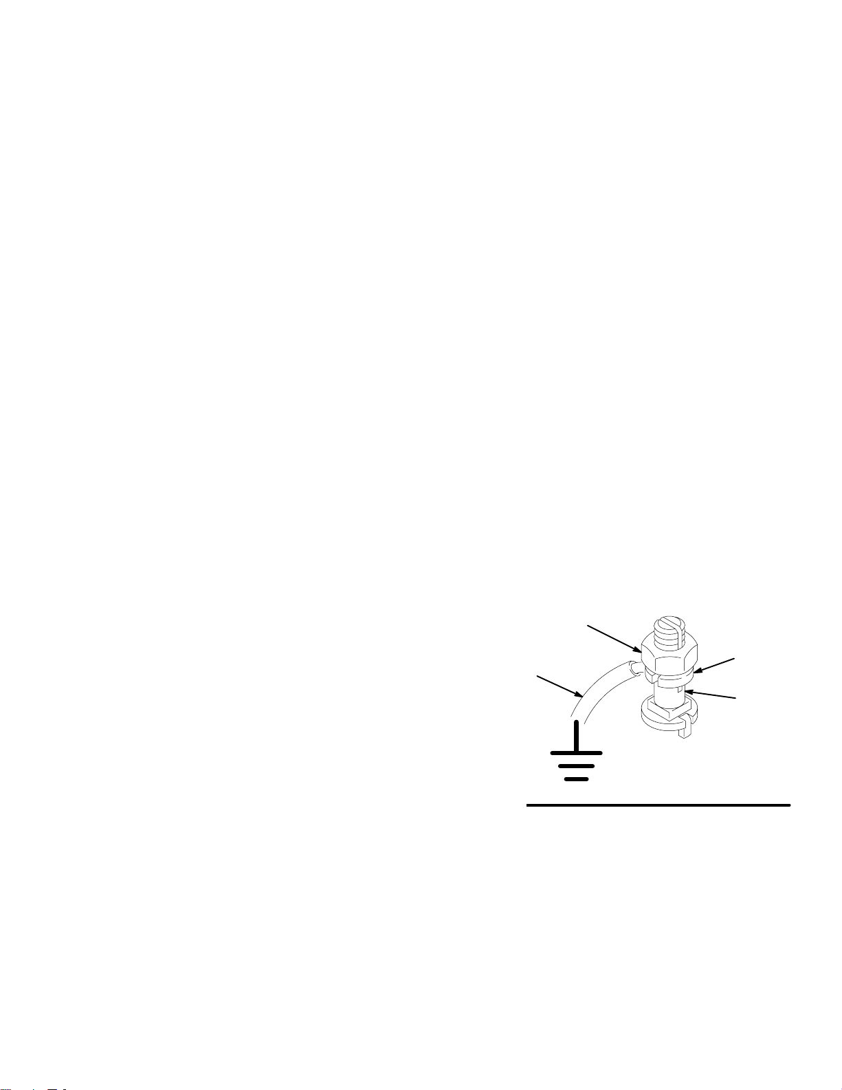
Grounding
To reduce the risk of static sparking, ground the pump,
object being sprayed, and all other spray equipment
used or located in the spray area. Check your local
electrical code for detailed grounding instructions for
your area and type of equipment. Be sure to ground all
of this spray equipment.
1. Pump: loosen the grounding lug locknut (W) and
washer (X). Insert one end of a 1.5 mm2 (12 ga)
minimum ground wire (Y) into the slot in lug (Z)
and tighten the locknut securely. See Fig. 1. Connect the other end of the wire to a true earth
ground. Order Part No. 237569 Ground Wire and
Clamp.
2. Air hoses: use only electrically conductive air
hoses.
3. Fluid hoses: use only electrically conductive fluid
hoses.
4. Heater, if used: refer to the Viscon2 Heater manual, 307805.
5. Air compressor: follow manufacturer’s recommendations.
6. Spray gun: grounding is obtained through connection to a properly grounded fluid hose and pump.
7. Fluid supply container: according to your local
code.
8. Object being sprayed: according to your local
code.
9. All solvent pails used when flushing, according to
local code. Use only metal pails, which are conductive, placed on a grounded surface. Do not
place the pail on a non-conductive surface, such
as paper or cardboard, which interrupts the
grounding continuity.
10. To maintain grounding continuity when flushing or
relieving pressure, always hold a metal part of the
spray gun firmly to the side of a grounded metal
pail, then trigger the spray gun.
W
X
Y
Z
0864
Fig. 1
5307929
Page 6
Installation
KEY
A
E
Y
F
31
62
G
B
31
A Air Line Filter
B Main Air Line
C Air Line Lubricator
D Fluid Hose
E Spray Gun
F Gun Air Supply Hose
G Bleed-Type Master Air Valve
(for accessories)
Y Ground Wire (required)
5 Pump
22 Suction Hose
5
23 Suction Tube
25 Fluid Filter
52
31 Air Regulators
52 Air Relief Valve
62 Bleed-Type Master Air Valve
(for pump)
65 Fluid Drain Valve
C
22
23
D
Fig. 2
WARNING
Three required components are supplied in your
system, to help reduce the risk of serious injury
including fluid injection, splashing in the eyes or on
the skin, overpressurization, or injury from moving
parts if you area adjusting or repairing the pump.
The bleed-type master air valve (62) relieves air
tapped between this valve and the pump. Trapped
air can cause the pump to cycle unexpectedly. To
bleed air from the pump, the pump air regulator
must be open when you close this valve.
25
65
0972A
Hose and Gun Connections
Refer to the Typical Installation drawing (Fig. 2). Connect one end of the fluid hose (D) to the filter (25)
outlet and the other to the fluid inlet of the gun (E). Do
not install the spray tip in the gun yet. To use a second
gun with the sprayer, refer to pages 11–13.
Close the bleed-type master air valve (62) and both
the air regulators (31). Connect the main air line (B) to
the bleed valve. Connect an air supply hose (F) to the
outlet nipple of the gun (left) air regulator. Connect the
other end of the hose to the gun’s air inlet.
The air relief valve (52) opens automatically to
relieve air pressure to the pump if the the pressure
exceeds a preset level. This vale prevents overpressurization of the spray gun.
The fluid drain valve (65) assists in relieving fluid
pressure in the displacement pump, hose, and gun;
triggering the gun to relieve pressure may not be
sufficient.
6 307929
Page 7
Installation
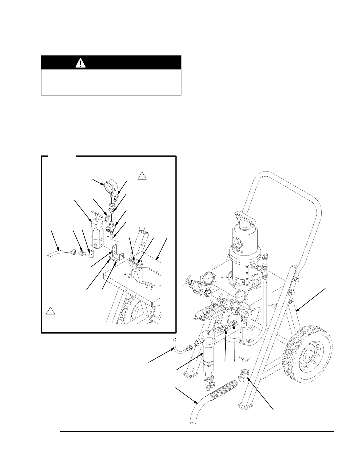
Installing Fluid Regulation Kit 222564
(Pump Model 231162)
WARNING
Before installing the fluid regulation kit, follow the
Pressure Relief Procedure on page 14. Disconnect all hoses from the pump.
Assemble the fluid regulation kit (66) as shown in
Detail A of Fig. 3. (Refer to the parts list on page 19.)
Install the mounting bracket (66k) on the regulator
(66f) using the two screws (66p) and lockwashers
(66q). Connect the fluid regulator and bracket to the
side of the cart (7) using the screw (66l), lockwasher
(66m) and nut (66n). Connect the 22” (560 mm) hose
(66h) to the outlet of the fluid filter (25).
DETAIL A
Fluid Regulation Kit 222564
includes items 66a–66q.
1
66d
66e66f
66b
66c
Connect the gun air supply hose (F) between the air
inlet of the gun (E) and the outlet nipple of the gun
(left) air regulator. See Fig. 2.
Connect the fluid hose (D) between the gun fluid inlet
and the outlet nipple (66b) of the fluid regulation kit.
66h 66j
66b
66k
1
Connect fluid hose here.
66a
66l
66m 66n
66p66q
66h (REF)
(SEE DETAIL A)
7
25
26
7
24
Fig. 3
22
21
0973B
7307929
Page 8
Installation
Converting the Pump to a Heated
Circulating System
To convert pump Model 231162 to a heated circulating
unit, order the following:
Viscon Fluid Heater, Model 220522
Heater Mounting Kit 222262
Circulating Kit 222436
Hose Kit 222264
WARNING
The Viscon2 Heater must be installed by a qualified
electrician in compliance with all state and local
codes and regulations, to reduce the risk of electric
shock or other serious injury during installation or
operation.
The heater requires a 120 VAC, single-phase, 16.7
Amp power supply. Refer to the Viscon2 Heater
Manual 307805 for further information.
Do not plug or unplug the power cord in any area
containing flammable materials or fumes to avoid
fire or explosion, which can result in serious injury.
Installing Heater Mounting Kit 222262
WARNING
NOTE: Reference numbers marked with an asterisk
(for example, 68*) are included in kit 222262.
Apply 110110 pipe sealant (included in the kit) to all
male threads, except at swiveling connections.
1. Remove the cover from the electrical box (H) at
the back of the heater (67). Screw the bushing
(74*) into the inlet of the electrical box. Install the
cord grip elbow (75*) in the bushing. See Fig. 4.
2. Thread the cord (76*) through the elbow (75*) and
into the electrical box. Attach the black lead to the
leftmost terminal, the white lead to the center
terminal, and the green ground wire to the rightmost terminal. Tighten all terminal nuts to 30 in–lb
(3.4 N.m). Tighten the nut on the cord grip elbow
(75*) to secure the cord. See Fig. 4.
WARNING
The electrical cord (76*) is rated for 105 C (221
F). Do not substitute a lower temperature rated,
generally available cord.
NOTE: Mount the heater (67) on the back of the cart
as follows. Two people are required to perform this
operation.
3. Align the heater (67) mounting posts with the four
holes at the back of the cart’s pump support bracket (J). See Fig. 5. Secure the heater to the bracket
with the M8 x 1.25 screws and lockwashers supplied with the heater.
Before installing the heater, heater mounting kit
and circulating kit, follow the Pressure Relief
Procedure on page 14. Disconnect all hoses from
the pump.
H
*74
*75
*76
Fig. 4
8 307929
4. Unscrew the swivel adapter (26) and remove the
fluid filter (25) from the pump (5). Remove the
adapter from the filter, and remove the 3/8 npt
nipple (24) from the pump fluid outlet. See Fig. 3.
WHITEBLACK
Tighten terminal nuts
1
to 30 in–lb (3.4 N.m).
1
1
GREEN
(GROUND)
0867
Page 9

C
Installation
5. Screw the check valve (70*) into the pump’s fluid
outlet, making certain that the arrow on the check
valve points away from the pump. Screw the rigid
end of the adapter (71*) onto the check valve. See
Fig. 5.
6. Install the 3/8 npt nipple (63*) in the heater outlet.
Screw the male end of the 90 swivel (19*) into the
inlet of the fluid filter (25). Screw the female end of
the swivel (19*) onto the nipple (63*) at the heater
outlet, and tighten securely.
7. Screw the elbow (72*) into the heater’s inlet.
Attach the 1/2” x 3’ (0.9 m) hose (73*) to the
elbow. Attach the other end of the hose to the
swivel of the adapter (71*) at the pump outlet.
5
7
*70
1
C
41
41
40
B
76*
82
40
80
REF)
83
82
81
38
74*75*
*73
(REF)
*71
J
78
79
67
19*
B
77
40
22
40
80
23
J
Fig. 5
PART OF
ITEM 67
*72
41
63*
1
73*
C
25
Arrow on body must point away from pump.
0974
9307929
Page 10

Installation
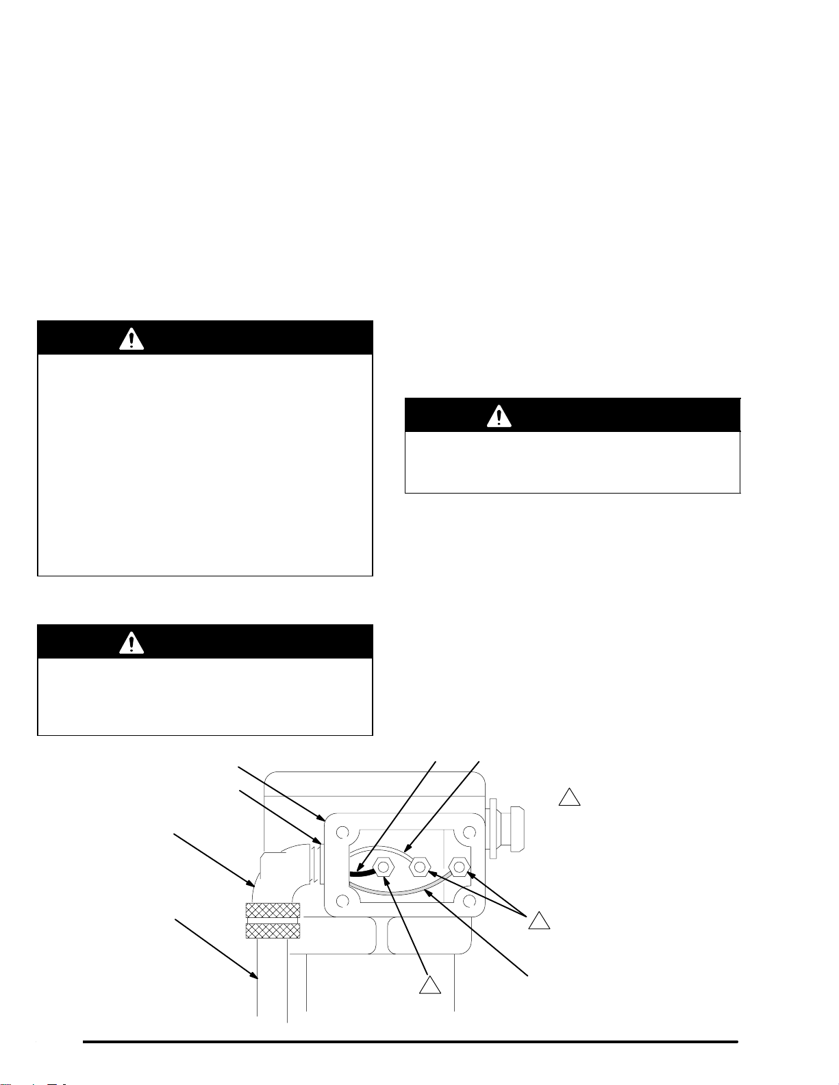
Installing Circulating Kit 222436
WARNING
Before installing the heater, heater mounting kit
and circulating kit, follow the Pressure Relief
Procedure on page 14. Disconnect all hoses from
the pump.
NOTE: Reference numbers marked with a symbol (for
example, 77), are included in kit 222436.
Apply 110110 pipe sealant (included in the kit) to all
male threads, except at swiveling connections.
1. Unscrew the suction hose (22) from the pump
intake elbow (21) and set the hose aside. Remove
the elbow (21) from the pump intake and discard.
See Fig. 3.
2. Screw the rigid end of the manifold (77) onto the
pump intake, and attach the suction hose (22) to
the swivel end of the manifold. See Fig. 5.
3. Place a washer (81) and insulator (82) on each
of the screws (38). Insert the screws through the
mounting holes on the left side of the pump support bracket (J), working from the inside. Place
another insulator (82) on each of the screws on
the outside of the bracket. Use the screws to
attach the back pressure regulator (83) to the
pump support bracket.
4. Screw one of the nipples (41) into the outlet in
the base of the back pressure regulator (83), then
screw one of the elbows (40) onto the nipple so
the male end of the elbow faces forward. Install
another elbow (40) in the inlet of the back pres-
sure regulator, then install the other nipple (41) in
the elbow. Install plugs in the other regulator
ports.
5. Screw an elbow (40) into the open port of the
pump fluid intake manifold (77), so the female
end of the elbow faces left. Install the CIRC end of
the three-way ball valve (78) in the elbow, so the
valve handle is at the front.
6. Screw a second elbow (40) onto the IN branch of
the three-way valve (78), so the elbow points
upward. Connect one end of the hose (80) to this
elbow, and the other end to the nipple (41) at the
outlet of the back pressure regulator.
7. Connect the drain hose (79) to the DRAIN end of
the three-way valve (78).
8. Connect the fluid return line to the nipple (41) at
the inlet of the back pressure regulator.
9. Connect the air and fluid hoses and gun as explained on page 6.
1
T
2
1
Connect air hose for first gun here
2
Connect air hose for second gun here
Fig. 6
31
N
M
L
SRP
M
30
29
NQ
Air Regulator Connections for a Two-Gun System (All Models)
0975B
10 307929
Page 11

Installation
Converting to a Two-Gun System
To convert your sprayer to a two-gun system, refer to
the following applicable paragraph for your model
(refer to page 12 for Models 231162, 224629 and
231161). Order the parts listed, and perform the assembly procedure.
Model 231158 (Refer to Figs. 6 and 7, and the Parts
Drawing on page 16)
WARNING
Before performing this procedure, follow the Pressure Relief Procedure on page 14. Disconnect all
hoses from the pump.
NOTE: Model 231158 includes a hose and gun set, so
you should order only one additional gun, air hose and
fluid hose.
Part No. Description Qty
156877 NIPPLE; 1/2 npt; 2.5” long 2
158683 ELBOW, 90; 1/2 npt (m x f) 2
103475 TEE; 1/2 npt(f) run;
1/2 npt(f) branch 1
104267 AIR REGULATOR 1
101180 GAUGE, pressure, air 1
100509 PLUG, pipe; 1/4 npt 1
166999 ELBOW, street, reducing;
1/2 npt(m) x 1/4 npt(f) 1
162453 NIPPLE; 1/4 npt x 1/4 npsm 2
100840 ELBOW, street, 90;
1/4 npt (m x f) 1
238852 GUN, spray, air-assisted airless 2
216069 HOSE, air; nylon; 1/4” ID;
cpld 1/4 npsm (fbe) swivel;
26 ft (7.9 m) long 2
214698 HOSE, fluid; nylon; 3/16” ID;
cpld 1/4 npsm(f) swivel x
1/4 npt(m); 25 ft (7.6 m) long 2
1. Remove the gun air regulator (31) from the nipple
(30) coming off the air manifold (29). Do not remove any parts from the regulator. Save the
regulator for use in step 4. See Fig. 6.
2. Install a 101180 Gauge (P) and 100509 Plug (Q)
on a 104267 Air Regulator (R). Screw a 166999
Elbow (S) into the outlet port of this air regulator,
and screw a 162453 Nipple (T) into the elbow.
3. Screw the branch of the 103475 Tee (L) onto the
nipple (30) at the air manifold (29). Install a
156877 Nipple (M) in each open port of the tee.
Screw a 158683 Elbow (N) onto each nipple.
4. Install the air regulator removed in step 1 onto one
of the elbows (N). This is the air control for the first
gun. Install the air regulator assembled in step 2
onto the other elbow (N), so both regulators are
facing the same way. This is the air control for the
second gun.
5. Remove the plug (27) from the optional outlet port
of the fluid filter (25). Install a 100840 Elbow (V)
and 162453 Nipple (T) in its place. See Detail A of
Fig. 7. This is the fluid connection for the second
gun.
6. Connect the fluid and air hoses to the guns as
explained on page 6 (see Detail D of Fig. 7).
11307929
Page 12

Installation
Model 231162 (Refer to Figs. 6 and 7, and the Parts
Drawing on page 18)
WARNING
Before performing this procedure, follow the Pressure Relief Procedure on page 14. Disconnect all
hoses from the pump.
NOTE: Model 231162 includes a hose and gun set, so
you should order only one 238852 Gun, 216069 Air
Hose, and 214698 Fluid Hose.
Part No. Description Qty
156877 NIPPLE; 1/2 npt; 2.5” long 2
158683 ELBOW, 90; 1/2 npt (m x f) 2
103475 TEE; 1/2 npt(f) run;
1/2 npt(f) branch 1
104267 AIR REGULATOR 1
101180 GAUGE, pressure, air 1
100509 PLUG, pipe; 1/4 npt 1
166999 ELBOW, street, reducing;
1/2 npt(m) x 1/4 npt(f) 1
103048 TEE, street; 1/4 npt(f) branch;
1/4 npt(f) x 1/4 npt(m) run 1
162453 NIPPLE; 1/4 npt x 1/4 npsm 2
238852 GUN, spray, air-assisted airless 1
216069 HOSE, air; nylon; 1/4” ID;
cpld 1/4 npsm (fbe) swivel;
26 ft (7.9 m) long 1
214698 HOSE, fluid; nylon; 3/16” ID;
cpld 1/4 npsm(f) swivel x
1/4 npt(m); 25 ft (7.6 m) long 1
Models 224629 and 231161 (Refer to Figs. 6 and 7,
and the Parts Drawing on page 20)
WARNING
Before performing this procedure, follow the Pressure Relief Procedure on page 14. Disconnect all
hoses from the pump.
NOTE: For Model 224629, order two 238852 Guns
and two 222264 Hose Kits. Model 231161 includes a
gun and a hose kit, so you should order only one
additional gun and hose kit.
Part No. Description Qty
156877 NIPPLE; 1/2 npt; 2.5” long 2
158683 ELBOW, 90; 1/2 npt (m x f) 2
103475 TEE; 1/2 npt(f) run;
1/2 npt(f) branch 1
104267 AIR REGULATOR 1
101180 GAUGE, pressure, air 1
100509 PLUG, pipe; 1/4 npt 1
166999 ELBOW, street, reducing;
1/2 npt(m) x 1/4 npt(f) 1
162453 NIPPLE; 1/4 npt x 1/4 npsm 3
100840 ELBOW, street, 90; 1/4 npt (m x f) 3
238852 GUN, spray, air-assisted airless 2
222264 HOSE KIT, insulated; nylon;
two fluid lines, one air line;
1/4” ID; cpld 1/4 npsm (fbe)
swivel; 25 ft (7.6 m) long 2
1. Perform steps 1–5 of the procedure for Model
231158 (see page 11).
2. Install the 100840 Elbow (V) in the optional inlet of
the back pressure valve (83). Screw a 162453
Nipple (T) into the elbow (V). See Detail C of Fig.
7. This is the return line connection for the second
gun.
1. Perform steps 1–4 of the procedure for Model
231158 (see page 11).
2. Unscrew the gauge (66d) from the cross (66c) of
the fluid regulation kit. Install the 103048 Tee (U) in
the cross (see Detail B of Fig. 7). Screw a 162453
Nipple (T) in the branch of the tee (U). Screw the
gauge (66d) in the open port of the tee. This is the
fluid connection for the second gun.
3. Connect the fluid and air hoses to the guns as
explained on page 6 (see Detail D of Fig. 7).
12 307929
3. Connect the fluid and air lines of one of the insulated hose kits (AA) to the fluid and air inlets of
one of the guns (E). Repeat for the other hose kit
and gun. See Detail E of Fig. 7.
4. Connect the air line of one of the hose kits (see
Detail E) to the outlet nipple of one of the air
regulators (see Fig. 6). Connect the air line of the
second hose kit to the outlet nipple of the other air
regulator.
5. Connect the fluid supply line of the first hose kit
(AA) to the outlet elbow (40) of the fluid filter (25).
Connect the fluid supply line of the second hose kit
to the other outlet elbow (V). See Detail A of Fig.
7. Similarly, connect the fluid return lines of the two
hose kits to the inlet nipples (41 and T) of the back
pressure regulator (83). See Detail C.
Page 13

DETAIL A: Hose Connections at Fluid
Filter (For All Models Except 231162)
DETAIL B: Hose Connections at Fluid
Regulator (Model 231162 Only)
40
25
V
1
41
DETAIL C: Fluid Return Connections at Back Pressure Valve (Models 224629 & 231161 Only)
T
2
83 T
0869B
4
40
V
3
41
66j
66d
T
2
U
66e
66b
1
66c
66a
DETAIL D: Assembly of Hoses and Gun
(Models 231158 and 231162 Only)
66b
66f
5
0976
E
1
To first gun
2
To second gun
3
From first gun
4
From second gun
5
From fluid filter
6
To 3-way valve
7
Fluid line
8
Air line
9
Fluid return line
40
80
41
F
D
6
0871A
0977
DETAIL E: Assembly of Hose Kit and Gun
(Models 224629 and 231161 Only)
E
8
7
8
9
7
Fig. 7
AA
0978
13307929
Page 14

Operation
Pressure Relief Procedure
WARNING
INJECTION HAZARD
Fluid under high pressure can be injected through the skin and cause
serious injury. To reduce the risk of an
injury from injection, splashing fluid, or moving
parts, follow the Pressure Relief Procedure
whenever you:
are instructed to relieve the pressure,
stop spraying,
check or service any of the system equipment,
or install or clean the spray tip.
1. Lock the spray gun trigger safety.
2. Shut off the main power to the heater, if used.
Circulate the fluid for at least 10 minutes to allow it
and the heater to cool.
3. Close the bleed-type master air valve (supplied in
your system).
4. Shut off the air regulators.
Flush the Pump Before Using
Pumps are tested with lightweight oil which is left in to
protect the pump parts. To prevent contamination of
the fluid, flush the pump with a compatible solvent
before using it.
WARNING
Before flushing, be sure the entire system and
flushing pails are properly grounded. Refer to
Grounding on page 5. Follow the Pressure
Relief Procedure at left, and remove the spray tip
from the gun. Always use the lowest possible fluid
pressure, and maintain firm metal-to-metal contact
between the gun and the pail during flushing to
reduce the risk of fluid injection, static sparking,
and splashing in the eyes or on the skin.
Starting and Adjusting the Pump
5. Unlock the spray gun trigger safety.
6. Hold a metal part of the spray gun firmly to the
side of a grounded metal pail, and trigger the
spray gun to relieve pressure.
7. Lock the spray gun trigger safety.
8. Open the drain valve (supplied in your system),
having a container ready to catch the drainage.
9. Leave the drain valve open until you are ready to
spray again.
If you suspect that the spray tip or hose is completely
clogged, or that pressure has not been fully relieved
after following the steps above, very slowly loosen the
air cap or hose end coupling and relieve pressure
gradually, then loosen completely. Now clear the tip or
hose.
WARNING
For your safety, before operating the equipment be
sure all operators have read and fully understand
all the warnings, cautions, and instructions in this
manual and all manuals supplied with each component or accessory.
Be sure the air regulators (31) and bleed-type master
air valve (62) are closed. Do not install the spray tip
yet!
Place the suction tube (23) in the fluid pail. Open the
drain valve (65) for priming. Open the bleed-type
master air valve and the gun air regulator (clockwise).
Hold a metal part of the spray gun firmly to the side of
a grounded metal pail and trigger the gun. Slowly open
the pump air regulator (clockwise) until the pump
starts. Allow the pump to cycle slowly until all the air is
pushed out of the fluid lines. Release the gun trigger
and engage the safety latch; the pump will stall against
the pressure.
With the pump and lines primed, and with adequate air
pressure and volume supplied, the pump will start and
stop as the spray gun is triggered and released.
Follow the Pressure Relief Procedure Warning at
left, then install the spray tip in the gun.
14 307929
Page 15

Operation
Use the pump air regulator to control the pump speed
and fluid pressure. Always use the lowest pressure
necessary to achieve the desired results. Higher
pressures waste fluid and cause premature wear of the
pump packings and spray tip.
The fluid regulator (66f) used on model 231162 is a
fluid pressure type. It allows you to run the pump at an
“efficient” air pressure (above 30 psi [2.1 bar]) while
adjusting fluid pressure with the regulator. The back
pressure regulator (83) used on models 224629 and
231161 does the same by requiring a minimum flow
rate and also setting the minimum circulating rate
needed to prevent fluid from settling.
Keep the wet-cup filled with Graco Throat Seal Liquid
(TSL) or other compatible solvent, to help prolong the
packing life.
Never allow the pump to run dry of the fluid being
pumped. A dry pump will quickly accelerate to a high
speed, possibly damaging itself. If your pump accelerates quickly, or is running too fast, stop it immediately
and check the fluid supply. If the supply container is
empty and air has been pumped into the lines, refill the
supply container and prime the pump and lines with
fluid, being sure to eliminate all air from the fluid system, or flush the pump as described in Shutdown and
Care, at right.
Heated Systems
Operating instructions for a heated circulating system
are provided in the Viscon Heater manual, 307805.
Read and understand all warnings and instructions in
the heater manual before operating a heated system.
The three-way ball valve (78) can be set for either fluid
circulation or draining. To circulate fluid back to the
pump, turn the handle toward the CIRC end of the
valve. To drain fluid, turn the handle toward the DRAIN
end.
Shutdown and Care
WARNING
To reduce the risk of serious injury whenever you
are instructed to relieve pressure, always follow the
Pressure Relief Procedure on page 14.
Always relieve the pressure whenever you shut off
the pump. Stop the pump at the bottom of its stroke to
keep fluid from drying on the exposed displacement
rod and damaging throat packings.
Always flush the pump with a compatible solvent
before the fluid can dry on the displacement rod, and
at the end of each day. If you are pumping waterbased fluid, flush first with water and then with mineral
spirits to protect the pump parts. If you are pumping
oil-based fluids, flush with mineral spirits only.
Relieve pressure and leave the mineral spirits in the
pump to prevent corrosion.
15307929
Page 16

Model 231158
39
Parts
5
7 (REF)
38
41
27 29
41
27
40
60
6162
30 31
See Detail Above
For Parts
24
26
34
32
20
3
1
4
A
6
7
52
57
33 (REF)
16 307929
25
64
65
86
84
85
22
A
21
33
23
0979B
Page 17

Model 231158
Parts
Ref
No. Part No. Description Qty
1 100016 LOCKWASHER, spring;1/4” 2
3 100022 CAPSCREW, hex hd;
1/4–20 x 3/4” long 2
4 100015 NUT, hex; 1/4–20 2
5 217523 10:1 MONARK PUMP
See 307595 for parts 1
6 188595 MOUNTING PLATE, pump 1
7 224044 CART, universal
See 308136 for parts 1
20 160790 NIPPLE; 3/8 npt 1
21 100349 ELBOW, 90; 3/4 npt (fbe) 1
22 214960 HOSE, suction; 3/4” ID; nylon;
coupled 3/4 npt (mbe);
3.5’ (1 m) long, w/spring guard 1
23 165767 SUCTION TUBE; 3/8 npt;
18” (457 mm) long 1
24 156849 NIPPLE; 3/8 npt; 1.5” long 1
25 218029 FLUID FILTER
See 307273 for parts 1
26 155665 UNION, adapter, straight;
3/8 npt(m) x 3/8 npsm(f) swivel 1
27 100509 PLUG, pipe, sq hd;1/4 npt 4
29 179749 MANIFOLD, air; 1/2 npt inlet;
two 1/2 npt outlets 1
30 156877 NIPPLE; 1/2 npt; 2.5” long 2
31 104267 AIR REGULATOR
0–125 psi (0–9 bar) range
See 308167 for parts 2
32 161037 UNION, adapter, 90;
1/2 npt(m) x 3/8 npsm(f) swivel 1
33 204560 HOSE, air; buna-N; 3/8” ID;
cpld 3/8 npt (mbe); 18” (457 mm) long 1
Ref
No. Part No. Description Qty
34 101180 GAUGE, pressure, air;
0–200 psi (0–14 bar) 2
38 102254 SCREW, hex hd; 1/4–20 x 7/8” long 2
39 166999 ELBOW, street, reducing;
1/2 npt(m) x 1/4 npt(f) 1
40 100840 ELBOW, street, 90; 1/4 npt (mxf) 1
41 162453 NIPPLE; 1/4 npt x 1/4 npsm 2
42 206994 THROAT SEAL LIQUID;
8 oz (not shown) 1
52 103347 VALVE, relief, air 1
57 171987 TEE; 3/8 npt x 1/4 npt run;
3/8 npt branch 1
60 222297 UNION, adapter, 45;
1/2 npt(m) x 1/2 npsm(f) swivel 1
61 158491 NIPPLE; 1/2 npt; 1–5/8” long 1
62 107142 VALVE, air, bleed-type; 1/2 npt (m x f) 1
64 150286 ADAPTER; 3/8 npt (m x f) 1
65 210658 DRAIN VALVE; 3/8 npt(mbe)
See 306861 for parts 1
84 238852 AIR-ASSISTED AIRLESS
SPRAY GUN
See 308640 for parts 1
85 216069 HOSE, air; nylon; 1/4” ID;
cpld 1/4 npsm (fbe) swivel;
26 ft (7.9 m) long 1
86 214698 HOSE, fluid; nylon; 3/16” ID;
cpld 1/4 npsm(f) swivel x
1/4 npt(m); 25 ft (7.6 m) long;
spring guards both ends 1
93 GG4XXX SPRAY TIP, customer choice 1
17307929
Page 18

Model 231162, Series B
66d
66c
66e
66f
66b
66a
66l
Parts
Ref. No. 66
Fluid Regulation Kit
includes items 66a–66q
66h
B
39
41
66j 66k
66b
66q
66p
27 29
66m
66n
7 (REF)
38
See Detail
At Left
For Parts
34
32
30 31
60
6162
27
40
41
B
24
26
5
20
3
1
4
A
52
57
33
6
7
18 307929
66h
(REF)
86
25
64
65
84
85
A
33 (REF)
22
21
23
0980B
Page 19

Model 231162, Series B
Parts
Ref
No. Part No. Description Qty
1 100016 LOCKWASHER, spring; 1/4” 2
3 100022 CAPSCREW, hex hd;
1/4–20 x 3/4” long 2
4 100015 NUT, hex; 1/4–20 2
5 217523 10:1 MONARK PUMP
See 307595 for parts 1
6 188595 MOUNTING PLATE, pump 1
7 224044 CART, universal
See 308136 for parts 1
20 160790 NIPPLE; 3/8 npt 1
21 100349 ELBOW, 90; 3/4 npt (fbe) 1
22 214960 HOSE, suction; 3/4” ID; nylon;
coupled 3/4 npt (mbe);
3.5’ (1 m) long, w/spring guard 1
23 165767 SUCTION TUBE; 3/8 npt;
18” (457 mm) long 1
24 156849 NIPPLE; 3/8 npt; 1.5” long 1
25 218029 FLUID FILTER
See 307273 for parts 1
26 155665 UNION, adapter, straight;
3/8 npt(m) x 3/8 npsm(f) swivel 1
27 100509 PLUG, pipe, sq hd; 1/4 npt 4
29 179749 MANIFOLD, air; 1/2 npt inlet;
two 1/2 npt outlets 1
30 156877 NIPPLE; 1/2 npt; 2.5” long 2
31 104267 AIR REGULATOR
0–125 psi (0–9 bar) range
See 308167 for parts 2
32 161037 UNION, adapter, 90;
1/2 npt(m) x 3/8 npsm(f) swivel 1
33 204560 HOSE, air; buna-N; 3/8” ID;
cpld 3/8 npt (mbe); 18” (457 mm) long 1
34 101180 GAUGE, pressure, air;
0–200 psi (0–14 bar) 2
38 102254 SCREW, hex hd; 1/4–20 x 7/8” long 2
39 166999 ELBOW, street, reducing;
1/2 npt(m) x 1/4 npt(f) 1
40 100840 ELBOW, street, 90; 1/4 npt (mxf) 1
41 162453 NIPPLE; 1/4 npt x 1/4 npsm 2
42 206994 THROAT SEAL LIQUID;
8 oz (not shown) 1
52 103347 VALVE, relief, air 1
57 171987 TEE; 3/8 npt x 1/4 npt run;
3/8 npt branch 1
60 222297 UNION, adapter, 45;
1/2 npt(m) x 1/2 npsm(f) swivel 1
Ref
No. Part No. Description Qty
61 158491 NIPPLE; 1/2 npt; 1–5/8” long 1
62 107142 VALVE, air, bleed-type; 1/2 npt (m x f) 1
64 150286 ADAPTER; 3/8 npt (m x f) 1
65 210658 DRAIN VALVE; 3/8 npt(mbe)
See 306861 for parts 1
66 222564 FLUID REGULATION KIT
Includes items 66a–66q 1
66a 210657 . VALVE, ball; 1/4 npt (mbe) 1
66b 162453 . NIPPLE; 1/4 npt x 1/4 npsm
(only 2 used with this sprayer) 3
66c 102959 . CROSS, pipe; 1/4 npt(f) 1
66d 101696 . GAUGE, pressure, fluid;
0–1000 psi (0–69 bar) range 1
66e 156971 . NIPPLE; 1/4 npt 1
66f 222121 . FLUID PRESSURE REGULATOR
See 307886 for parts 1
66g 110220 . ADAPTER, 45; 1/4 npt(m) x
1/4 npsm(f) swivel 1
66h 110192 . HOSE; PTFE; 0.20” ID;
cpld 1/4 npsm (fbe) swivel;
22” (560 mm) long 1
66j 100840 . ELBOW, street, 90; 1/4 npt (m x f)
(only 1 used with this sprayer) 2
66k 185251 . BRACKET, regulator 1
66l 100469 . SCREW, cap, hex hd;
3/816 x 3/4” long 1
66m 100133 . LOCKWASHER; 3/8” 1
66n 100307 . NUT, hex; 3/8–16 unc 1
66p 100270 . SCREW, cap, hex hd;
1/4–20 x 5/8” long 2
66q 100016 . LOCKWASHER; 1/4” 2
84 238852 AIR-ASSISTED AIRLESS
SPRAY GUN
See 308640 for parts 1
85 216069 HOSE, air; nylon; 1/4” ID;
cpld 1/4 npsm (fbe) swivel;
26 ft (7.9 m) long 1
86 214698 HOSE, fluid; nylon; 3/16” ID;
cpld 1/4 npsm(f) swivel x
1/4 npt(m); 25 ft (7.6 m) long;
spring guards both ends 1
93 GG4XXX SPRAY TIP, customer choice 1
This part of the Fluid Regulation Kit is not pictured as it is
not used on this sprayer.
19307929
Page 20

Model 224629, Series A
B
Includes items 1–83
Model 231161
Includes items 1–92
83
40
41
80
REF)
39
41
41
B
27 29
82
40
81
38
7 (REF)
38
C
32
34
Parts
See Detail
At Left
For Parts
71*73*
70*
80
52
57
33
6
7
1
4
20
A
5
3
B
60
6162
Ref. No. 85 Hose Kit
Includes Items 86–92
84
92
30 31
91
90
79
78
7 (REF)
88
89
87
*75
*76
74*
22
23
40
A
33 (REF)
77
67 63*
25
64
22 (REF)
27
19*
41
86
20 307929
Part Of
Item 67
65
72*
C
73*(REF)
0981
Page 21

Model 224629, Series A
Includes items 1–83
Model 231161
Includes items 1–92
Parts
Ref
No. Part No. Description Qty
1 100016 LOCKWASHER, spring; 1/4” 2
3 100022 CAPSCREW, hex hd;
1/4–20 x 3/4” long 2
4 100015 NUT, hex; 1/4–20 2
5 217523 10:1 MONARK PUMP
See 307595 for parts 1
6 188595 MOUNTING PLATE, pump 1
7 224044 CART, universal
See 308136 for parts 1
19* 155494 ADAPTER, union, 90;
3/8 npt(m) x 3/8 npt(f) swivel 1
20 160790 NIPPLE; 3/8 npt 1
22 214960 HOSE, suction; 3/4” ID; nylon;
coupled 3/4 npt (mbe);
3.5’ (1 m) long, w/spring guard 1
23 165767 SUCTION TUBE; 3/8 npt;
18” (457 mm) long 1
25 218029 FLUID FILTER
See 307273 for parts 1
27 100509 PLUG, pipe, sq hd; 1/4 npt 4
29 179749 MANIFOLD, air; 1/2 npt inlet;
two 1/2 npt outlets 1
30 156877 NIPPLE; 1/2 npt; 2.5” long 2
31 104267 AIR REGULATOR
0–125 psi (0–9 bar) range
See 308167 for parts 2
32 161037 UNION, adapter, 90;
1/2 npt(m) x 3/8 npsm(f) swivel 1
33 204560 HOSE, air; buna-N; 3/8” ID;
cpld 3/8 npt (mbe); 18” (457 mm) long 1
34 101180 GAUGE, pressure, air;
0–200 psi (0–14 bar) 2
38 102254 SCREW, hex hd; 1/4–20 x 7/8” long 4
39 166999 ELBOW, street, reducing;
1/2 npt(m) x 1/4 npt(f) 1
40 100840 ELBOW, street, 90; 1/4 npt (m x f) 4
41 162453 NIPPLE; 1/4 npt x 1/4 npsm 4
52 103347 VALVE, relief, air 1
57 171987 TEE; 3/8 npt x 1/4 npt run;
3/8 npt branch 1
60 222297 UNION, adapter, 45;
1/2 npt(m) x 1/2 npsm(f) swivel 1
61 158491 NIPPLE; 1/2 npt; 15–/8” long 1
62 107142 VALVE, air, bleed-type; 1/2 npt (m x f) 1
63* 156849 NIPPLE; 3/8 npt 1
64 150286 ADAPTER; 3/8 npt (m x f) 1
65 210658 DRAIN VALVE; 3/8 npt(mbe)
See 306861 for parts 1
67 220522 VISCON HEATER (120V)
See 307805 for parts 1
70* 206962 CHECK VALVE; 3/8 npt (mbe) 1
Ref
No. Part No. Description Qty
71* 159801 UNION, adapter, 90;
3/8 npt(f) x 1/2 npsm(f) swivel 1
72* 158683 ELBOW, 90; 1/2 npt (m x f) 1
73* 235022 HOSE, fluid; nylon; 1/2” ID;
cpld 1/2 npt (mbe); 3’ (0.9 m) long 1
74* 107219 BUSHING; 3/4 npt(m) x 1/2 npt(f) 1
75* 102363 ELBOW, cord grip, 90;
1/2 npt(m); includes nut,
washer, and grommet 1
76* 110160 CORD ASSY, heater; 12 AWG;
600V; 20 AMP; 105C (221F);
6.5 ft (2 m) long 1
77 166998 MANIFOLD, inlet; 1/4 npt(f) x
3/4 npt(f) x 3/4 npsm(f) swivel 1
78 214711 BALL VALVE, three-way; 1/4 npt(m);
See 306861 for parts 1
79 206965 HOSE, drain; nylon; 1/4” ID;
cpld 1/4 npsm(f) 1
80 206966 HOSE; PTFE; 1/4” ID;
cpld 1/4 npsm (fbe) swivel;
18” (457 mm) long 1
81 100527 WASHER, wrought; 1/4” 2
82 167002 INSULATOR, heat 4
83 222405 REGULATOR, back pressure
See 306860 for parts 1
84 238852 AIR-ASSISTED AIRLESS
SPRAY GUN
See 308640 for parts 1
85 222264 HOSE KIT
Includes items 86–92 1
86 222407 . HOSE, insulated; two fluid
lines, one air line; nylon;
1/4” ID; cpld 1/4 npsm (fbe)
swivel; 25 ft (7.6 m) long 1
87 169797 . NIPPLE; 1/4 npsm x 1/8 npt 2
88 169795 . MANIFOLD; 1/8 npt(f) 1
89 100139 . PLUG, hex socket; 1/8 npt 1
90 159840 . ADAPTER; 1/8 npt(m) x 1/4 npt(f) 1
91 214701 . HOSE, fluid; nylon; 3/16” ID;
cpld 1/4 npt(m) x 1/4 npsm(f)
swivel; 3 ft (0.9 m) long 1
92 210500 . FILTER, fluid, in-line;
100 mesh; 1/4 npsm(m) x
1/4 npsm(f) swivel 1
93 GG4XXX SPRAY TIP, customer choice 1
* These parts are included in Heater Mounting Kit 222262,
which may be purchased separately. See page 23.
These parts are included in Circulating Kit 222436, which
may be purchased separately. See page 23.
21307929
Page 22

Notes
22 307929
Page 23

Conversion Kits
Heater Mounting Kit 222262
Required to convert Model 231158 to a heated unit.
Consists of:
Ref. No. Qty Ref. No. Qty
19 1 73 1
63 1 74 1
70 1 75 1
71 1 76 1
72 1
Also includes 6 ml supply of sst pipe sealant 110110.
Manual Change Summary
Circulating Kit 222436
Required to convert Model 231158 to a circulating unit.
Consists of:
Ref. No. Qty Ref. No. Qty
38 2 79 1
40 4 80 1
41 2 81 2
77 1 82 4
78 1 83 1
Also includes 6 ml supply of sst pipe sealant 110110.
Kit 222436 includes some parts not required for this
pump: 156953 Mounting Stud, 100639 Lockwashers,
100023 Washer, 100307 Nut, and 102814 Gauge.
This manual was revised to include the changes from
PCN H.
Technical Data
Maximum working pressure 950 psi (6.6 MPa, 66 bar). . . . . . . . . . . . . . . . . . . . . . . .
Maximum incoming air pressure 95 psi (0.66 MPa, 6.6 bar). . . . . . . . . . . . . . . . . . . . .
Ratio 10:1. . . . . . . . . . . . . . . . . . . . . . . . . . . . . . . . . . . . . . . . . . . . . . . . . . . . . . . . . . . . . . .
Maximum recommended
pump speed 60 cpm (1.0 gpm [3.8 liters/min]). . . . . . . . . . . . . . . . . . . . . . . . . . . . . . .
at continuous operation
Air consumption approx. 15 scfm. . . . . . . . . . . . . . . . . . . . . . . . . . . . . . . . . . . . . . . . . . .
(0.43 m3/min) at 1.0 gpm
(3.8 liter/min) flow rate at
95 psi (0.66 MPa, 6.6 bar) air pressure
Wetted parts See separate component instruction manuals. . . . . . . . . . . . . . . . . . . .
23307929
Page 24

Graco Standard Warranty
Graco warrants all equipment manufactured by Graco and bearing its name to be free from defects in material and workmanship on the
date of sale to the original purchaser for use. With the exception of any special, extended, or limited warranty published by Graco,
Graco will, for a period of twelve months from the date of sale, repair or replace any part of the equipment determined by Graco to be
defective. This warranty applies only when the equipment is installed, operated and maintained in accordance with Graco’s written
recommendations.
This warranty does not cover, and Graco shall not be liable for general wear and tear, or any malfunction, damage or wear caused by
faulty installation, misapplication, abrasion, corrosion, inadequate or improper maintenance, negligence, accident, tampering, or substitution of non–Graco component parts. Nor shall Graco be liable for malfunction, damage or wear caused by the incompatibility of
Graco equipment with structures, accessories, equipment or materials not supplied by Graco, or the improper design, manufacture,
installation, operation or maintenance of structures, accessories, equipment or materials not supplied by Graco.
This warranty is conditioned upon the prepaid return of the equipment claimed to be defective to an authorized Graco distributor for
verification of the claimed defect. If the claimed defect is verified, Graco will repair or replace free of charge any defective parts. The
equipment will be returned to the original purchaser transportation prepaid. If inspection of the equipment does not disclose any defect
in material or workmanship, repairs will be made at a reasonable charge, which charges may include the costs of parts, labor, and
transportation.
THIS WARRANTY IS EXCLUSIVE, AND IS IN LIEU OF ANY OTHER WARRANTIES, EXPRESS OR IMPLIED, INCLUDING BUT
NOT LIMITED TO WARRANTY OF MERCHANTABILITY OR WARRANTY OF FITNESS FOR A PARTICULAR PURPOSE.
Graco’s sole obligation and buyer’s sole remedy for any breach of warranty shall be as set forth above. The buyer agrees that no other
remedy (including, but not limited to, incidental or consequential damages for lost profits, lost sales, injury to person or property, or any
other incidental or consequential loss) shall be available. Any action for breach of warranty must be brought within two (2) years of the
date of sale.
Graco makes no warranty, and disclaims all implied warranties of merchantability and fitness for a particular purpose in connection
with accessories, equipment, materials or components sold but not manufactured by Graco. These items sold, but not manufactured
by Graco (such as electric motors, switches, hose, etc.), are subject to the warranty, if any, of their manufacturer. Graco will provide
purchaser with reasonable assistance in making any claim for breach of these warranties.
In no event will Graco be liable for indirect, incidental, special or consequential damages resulting from Graco supplying equipment
hereunder, or the furnishing, performance, or use of any products or other goods sold hereto, whether due to a breach of contract,
breach of warranty, the negligence of Graco, or otherwise.
FOR GRACO CANADA CUSTOMERS
The parties acknowledge that they have required that the present document, as well as all documents, notices and legal proceedings
entered into, given or instituted pursuant hereto or relating directly or indirectly hereto, be drawn up in English. Les parties reconnaissent avoir convenu que la rédaction du présente document sera en Anglais, ainsi que tous documents, avis et procédures judiciaires
exécutés, donnés ou intentés à la suite de ou en rapport, directement ou indirectement, avec les procedures concernées.
Graco Information
TO PLACE AN ORDER, contact your Graco distributor, or call one of the following numbers
to identify the distributor closest to you:
1–800–367–4023 Toll Free
612–623–6921
612–378–3505 Fax
All written and visual data contained in this document reflects the latest product information available at the time of publication.
Graco reserves the right to make changes at any time without notice.
International Offices: Belgium, Korea, Hong Kong, Japan
Sales Office: Minneapolis
www.graco.com
PRINTED IN USA 307929 1988, Revised 12/2003
24 307929
 Loading...