

Page 1
Instructions - Parts
PCF
313377L
Precision Dispense System
Electronically-controlled fluid metering system that provides precise continuous flow of
single-component sealants and adhesives through closed-loop technology.
Not for use in explosive atmospheres.
For professional use only.
Important Safety Instructions
Read all warnings and instructions in this
manual. Save these instructions.
See page 4 for model information. See page 5 for
maximum working pressure and approvals.
EN
IMPORTANT:
This manual does not apply to some PCF systems. See note on page 3 to verify this is the
correct manual for your PCF system.
Page 2

Contents
Related Manuals . . . . . . . . . . . . . . . . . . . . . . . . . . . 3
Models . . . . . . . . . . . . . . . . . . . . . . . . . . . . . . . . . . . 4
Fluid Plate Assemblies . . . . . . . . . . . . . . . . . . . . 5
Control Center Assemblies . . . . . . . . . . . . . . . . . 5
Warnings . . . . . . . . . . . . . . . . . . . . . . . . . . . . . . . . . 6
System Configurations . . . . . . . . . . . . . . . . . . . . . . 8
Typical Ambient System Installation . . . . . . . . . . 8
Typical Heated System Installation . . . . . . . . . . . 9
Overview . . . . . . . . . . . . . . . . . . . . . . . . . . . . . . . . . 10
System Overview . . . . . . . . . . . . . . . . . . . . . . . 10
System Components . . . . . . . . . . . . . . . . . . . . . 10
Fluid Plate Assembly Overview . . . . . . . . . . . . 11
Control Center Assembly Overview . . . . . . . . . 13
Installation . . . . . . . . . . . . . . . . . . . . . . . . . . . . . . . 16
Before Installation . . . . . . . . . . . . . . . . . . . . . . . 16
Overview . . . . . . . . . . . . . . . . . . . . . . . . . . . . . . 16
Install Control Center . . . . . . . . . . . . . . . . . . . . 17
Install Fluid Plate Assembly . . . . . . . . . . . . . . . 19
Install Cable Assemblies . . . . . . . . . . . . . . . . . . 22
Install Gateway Module Interface . . . . . . . . . . . 23
System Setup . . . . . . . . . . . . . . . . . . . . . . . . . . . . . 25
Overview . . . . . . . . . . . . . . . . . . . . . . . . . . . . . . 25
Configure Control Settings . . . . . . . . . . . . . . . . 26
Configure Mode Settings . . . . . . . . . . . . . . . . . 27
Configure Delay Settings . . . . . . . . . . . . . . . . . 28
Configure Flow Meter Settings . . . . . . . . . . . . . 28
Configure Control Loop Settings . . . . . . . . . . . . 29
Adjust Pressure Sensors . . . . . . . . . . . . . . . . . 29
Configure Errors . . . . . . . . . . . . . . . . . . . . . . . . 30
Setup Maintenance Schedule/Parameters . . . . 31
Configure Gateway Settings . . . . . . . . . . . . . . . 31
Setup Styles . . . . . . . . . . . . . . . . . . . . . . . . . . . 31
Configure Advanced Settings . . . . . . . . . . . . . . 31
On/Off Delays . . . . . . . . . . . . . . . . . . . . . . . . . . 32
Operation . . . . . . . . . . . . . . . . . . . . . . . . . . . . . . . . 33
Startup . . . . . . . . . . . . . . . . . . . . . . . . . . . . . . . 33
Load Material . . . . . . . . . . . . . . . . . . . . . . . . . . 33
Maintenance Mode Operation . . . . . . . . . . . . . . 34
Automation Control (Normal) Operation . . . . . . 37
Jobs . . . . . . . . . . . . . . . . . . . . . . . . . . . . . . . . . 37
Styles . . . . . . . . . . . . . . . . . . . . . . . . . . . . . . . . 38
Precharge Modes . . . . . . . . . . . . . . . . . . . . . . . 39
Typical Job Cycle . . . . . . . . . . . . . . . . . . . . . . . 41
Pressure Relief Procedure . . . . . . . . . . . . . . . . . . 46
Shutdown . . . . . . . . . . . . . . . . . . . . . . . . . . . . . . . . 47
USB Data . . . . . . . . . . . . . . . . . . . . . . . . . . . . . . . . . 48
USB Logs . . . . . . . . . . . . . . . . . . . . . . . . . . . . . 48
System Configuration Settings File . . . . . . . . . . 48
Custom Language File . . . . . . . . . . . . . . . . . . . 49
Download Procedure . . . . . . . . . . . . . . . . . . . . . 49
Upload Procedure . . . . . . . . . . . . . . . . . . . . . . . 50
Troubleshooting . . . . . . . . . . . . . . . . . . . . . . . . . . . 51
Fluid Modules . . . . . . . . . . . . . . . . . . . . . . . . . . 51
Fluid Meter . . . . . . . . . . . . . . . . . . . . . . . . . . . . . 52
Fluid Regulator . . . . . . . . . . . . . . . . . . . . . . . . . 52
Dispense Valves . . . . . . . . . . . . . . . . . . . . . . . . 53
Gateway Module . . . . . . . . . . . . . . . . . . . . . . . . 54
LED Diagnostic Information . . . . . . . . . . . . . . . . 54
Errors . . . . . . . . . . . . . . . . . . . . . . . . . . . . . . . . . . . 55
View Errors . . . . . . . . . . . . . . . . . . . . . . . . . . . . 55
Diagnose Errors . . . . . . . . . . . . . . . . . . . . . . . . . 55
Clear Errors and Reset Control Unit . . . . . . . . . 55
Error Codes and Troubleshooting . . . . . . . . . . . 55
Maintenance . . . . . . . . . . . . . . . . . . . . . . . . . . . . . . 62
Maintenance Schedule . . . . . . . . . . . . . . . . . . . 62
Advanced Display Module (ADM) . . . . . . . . . . . 63
Upgrade Gateway Module Software . . . . . . . . . 63
Upgrade Gateway Module Fieldbus Map . . . . . 64
Upgrade Fluid Control Module (FCM) Software 65
Air Filter Maintenance . . . . . . . . . . . . . . . . . . . . 65
Repair . . . . . . . . . . . . . . . . . . . . . . . . . . . . . . . . . . . 66
Fluid Plate Assembly . . . . . . . . . . . . . . . . . . . . . 66
Control Center Assembly . . . . . . . . . . . . . . . . . . 74
Parts . . . . . . . . . . . . . . . . . . . . . . . . . . . . . . . . . . . . 78
Control Center Assembly Parts . . . . . . . . . . . . . 78
Fluid Plate Assembly Parts . . . . . . . . . . . . . . . . 80
Appendix A - Advanced Display Module (ADM) . 85
Display Overview . . . . . . . . . . . . . . . . . . . . . . . . 85
Display Details . . . . . . . . . . . . . . . . . . . . . . . . . . 85
Setup Mode . . . . . . . . . . . . . . . . . . . . . . . . . . . . 87
Run Mode . . . . . . . . . . . . . . . . . . . . . . . . . . . . . 95
Appendix B - Discrete Gateway Module (DGM)
Connection Details . . . . . . . . . . . . . . . . . . . . . 98
D-Sub Cable 123793 . . . . . . . . . . . . . . . . . . . . . 98
D-Sub Cable 123792 and Breakout Board 123783
99
DGM Digital Input . . . . . . . . . . . . . . . . . . . . . . 102
DGM Digital Outputs . . . . . . . . . . . . . . . . . . . . 103
DGM Analog Inputs . . . . . . . . . . . . . . . . . . . . . 104
DGM Analog Outputs . . . . . . . . . . . . . . . . . . . 104
2 313377L
Page 3
Related Manuals
ADM Software Part No. 16K405
(see manual 3A2098)
ADM Software Part No. 16F528 or 15V769
(use this manual)
Appendix C - Communications Gateway Module
(CGM) Connection Details . . . . . . . . . . . . . . 105
Install Fieldbus Connections . . . . . . . . . . . . . . 105
CGM I/O Data Map . . . . . . . . . . . . . . . . . . . . . 108
Appendix D - I/O Signal Descriptions . . . . . . . . 111
Automation Inputs . . . . . . . . . . . . . . . . . . . . . . 111
Automation Outputs . . . . . . . . . . . . . . . . . . . . . 112
Technical Data . . . . . . . . . . . . . . . . . . . . . . . . . . . 114
Fluid Plate Assembly Technical Data . . . . . . . 115
Control Center Assembly Technical Data . . . . 115
Graco Standard Warranty . . . . . . . . . . . . . . . . . . 116
Graco Information . . . . . . . . . . . . . . . . . . . . . . . . 116
Related Manuals
The following is a list of component manuals written in
English. These manuals and any available translations
can be found at www.graco.com.
Manual Description
3A2098
307517
308647
309834
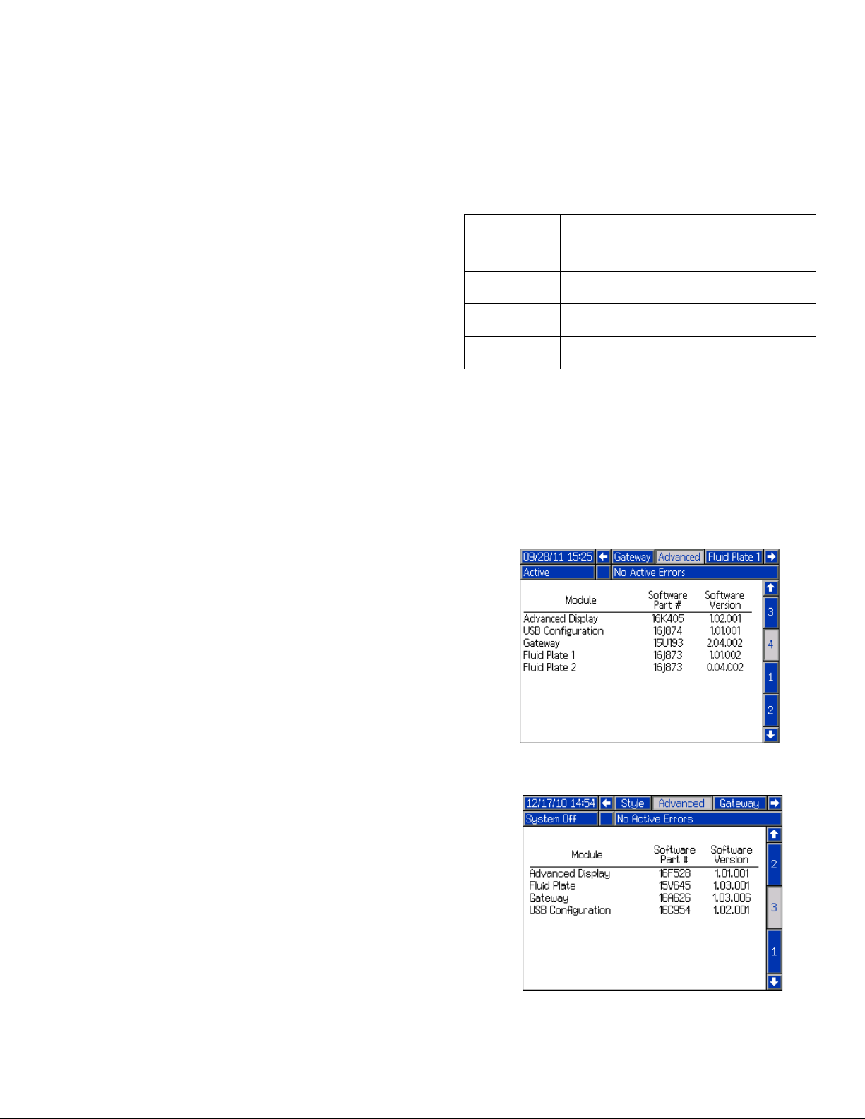
NOTE: In the Advanced screens on your system, if
the Advanced Display software part number shown
is 16K405 then this manual does not apply to your
system; refer to manual 3A2098 for your system.
Otherwise, the part number shown should be
16F528 or 15V769 and you should use this manual.
New PCF Instructions - Parts
(see the note below)
Mastic Fluid Regulators Instructions-Parts
Fluid Pressure Regulators Instructions-Parts
Helical Gear Fluid Flow Meters Instructions-Parts
313377L 3
Page 4
Models
Models
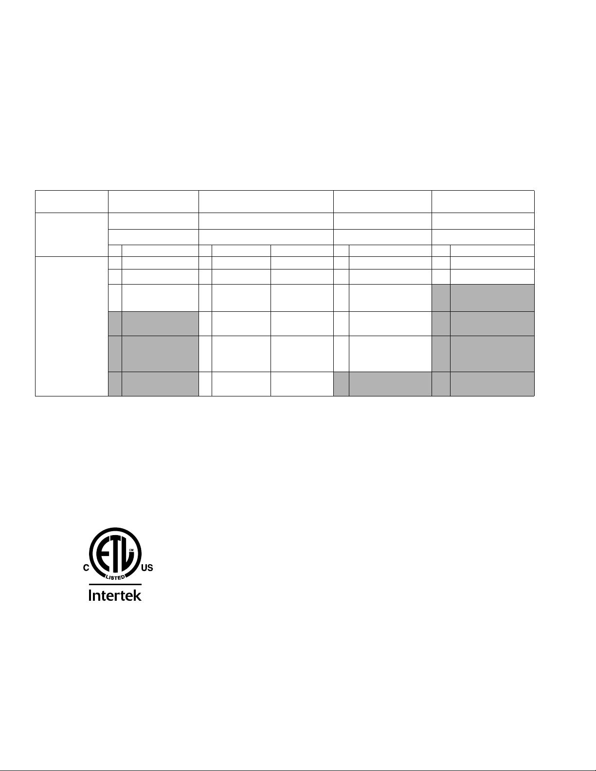
Check the identification (ID) plate for the 6-digit part number of the fluid metering system. Use the following matrix to
define the construction of the system, based on the six digits. For example, Part PF1110 represents a PCF fluid
metering system (PF), a two style system (1), a fluid plate with a cartridge regulator and no meter (1), a DeviceNet
user interface (1) with a 100-240 Vac power supply (0).
NOTE: To order replacement parts, see Parts section in this manual. The digits in the matrix do not correspond to the Ref. Nos. in the Parts drawings and lists.
™
PF
First and
Second Digits
1 2 Styles 1 Cartridge None 0 Discrete 0 100 - 240 Vac
2
3 256 Styles 3 Cartridge High
PF
(Precision
Continuous
Flow)
Discrete Gateway systems do not include automation interface cables. The following Graco accessories are avail-
able for wiring to the automation system. Installers should follow Appendix B - Discrete Gateway Module
(DGM) Connection Details, page 98, for custom wiring.
50 ft (15 m) cable with flying leads (123793)
Breakout board (123783) and 50 ft (15 m) cable (123792)
1
Third Digit
Style/Size
Description Regulator Meter Description Description
16 Styles 2 Mastic None 1
4 Mastic High
5 Heated
Mastic
6 Heated
Mastic
1
Fourth Digit
Fluid Plate
Resolution
Resolution
Standard
Resolution
Heated
None
Fifth Digit
User Interface
DeviceNet
2
EtherNet/IP
3
PROFIBUS
4
PROFINET
1
0
Sixth Digit
Voltage
™
1 24 Vdc
™
™
™
Fluid metering systems with ETL certification and Canadian approval.
NOTE: Fluid metering systems with heated mastic regulators are not ETL certified.
1
C
Certified to CAN/CSA C22.2 No. 61010-1
This product has been tested to the requirements of CAN/CSA-C22.2 No. 61010-1, second edition, including Amendment 1, or a later version of the same standard incorporating the same level of testing requirements.
4 313377L
9902471
Conforms to
UL 61010-1
Page 5
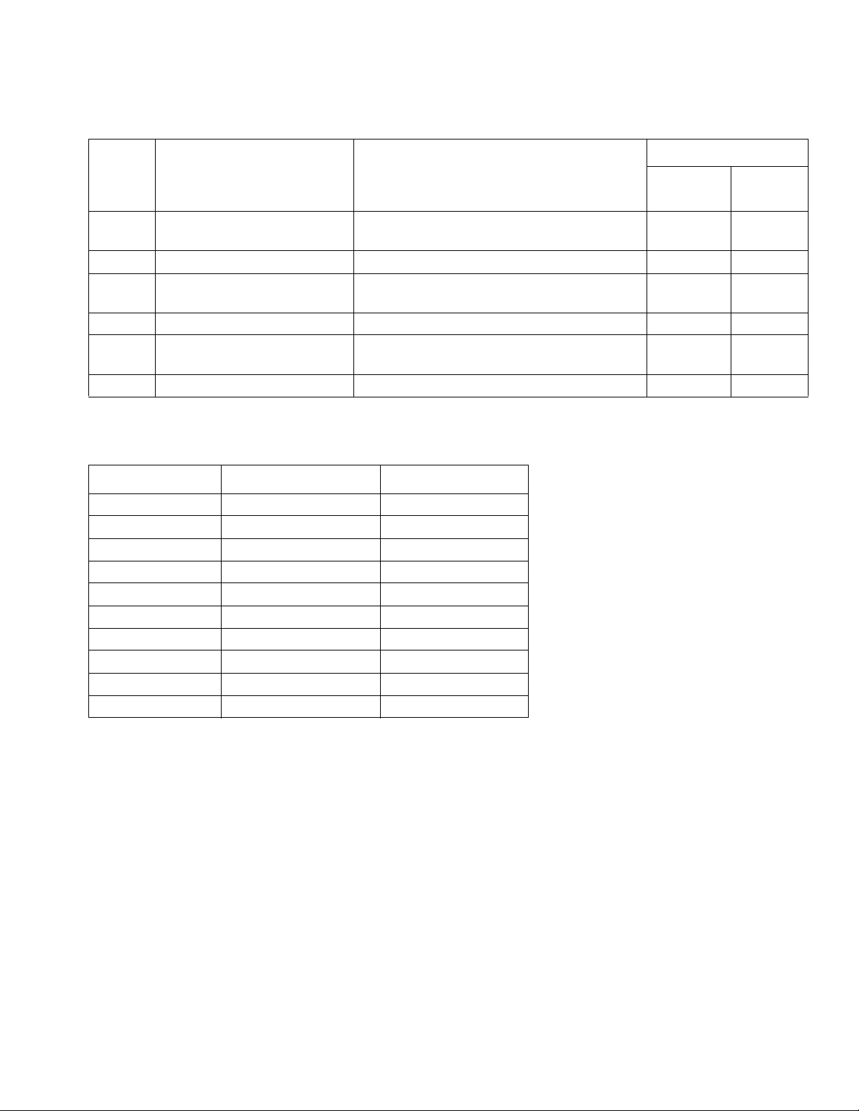
Fluid Plate Assemblies
Models
Maximum Working
Pressure
Part
24B958 6000 psi (41.4 MPa, 414 bar) Cartridge Regulator,
24B959 6000 psi (41.4 MPa, 414 bar) Cartridge Regulator, No Flow Meter 244734 --
24B960 5000 psi (34.4 MPa, 344 bar) Mastic Regulator,
24B961 5000 psi (34.4 MPa, 344 bar) Mastic Regulator, No Flow Meter 246642 --
24B962 5000 psi (34.4 MPa, 344 bar) Heated Mastic Regulator,
24C901 5000 psi (34.4 MPa, 344 bar) Heated Mastic Regulator, No Flow Meter 246643 --
psi (MPa, bar) Description
High Resolution Flow Meter
High Resolution Flow Meter
Standard Resolution Heated Flow Meter
Includes:
Regulator
244734 246652
246642 246652
246643 246340
Control Center Assemblies
Description Bus Module Bus Module Part
100 - 240 Vac DeviceNet 15V759
100 - 240 Vac EtherNet/IP 15V760
100 - 240 Vac PROFIBUS 15V761
100 - 240 Vac PROFINET 15V762
100 - 240 Vac Discrete 24B681
24 Vdc DeviceNet 15V759
24 Vdc EtherNet/IP 15V760
24 Vdc PROFIBUS 15V761
24 Vdc PROFINET 15V762
24 Vdc Discrete 24B681
Flow
Meter
Discrete Gateway systems do not include automation interface cables. The following Graco accessories are avail-
able for wiring to the automation system. Installers should follow Appendix B - Discrete Gateway Module
(DGM) Connection Details, page 98, for custom wiring.
50 ft (15 m) cable with flying leads (123793)
Breakout board (123783) and 50 ft (15 m) cable (123792)
313377L 5
Page 6
Warnings
Warnings
The following warnings are for the setup, use, grounding, maintenance, and repair of this equipment. The exclamation point symbol alerts you to a general warning and the hazard symbol refers to procedure-specific risk. Refer back
to these warnings. Additional, product-specific warnings may be found throughout the body of this manual where
applicable.
WARNING
ELECTRIC SHOCK HAZARD
Improper grounding, setup, or usage of the system can cause electric shock.
• Turn off and disconnect power at main switch before disconnecting any cables and before servicing
equipment.
• Connect only to grounded power source.
• All electrical wiring must be done by a qualified electrician and comply with all local codes and
regulations.
SKIN INJECTION HAZARD
High-pressure fluid from dispensing device, hose leaks, or ruptured components will pierce skin. This
may look like just a cut, but it is a serious injury that can result in amputation. Get immediate surgical
treatment.
• Engage trigger lock when not dispensing.
• Do not point dispensing device at anyone or at any part of the body.
• Do not put your hand over the fluid outlet.
• Do not stop or deflect leaks with your hand, body, glove, or rag.
• Follow the Pressure Relief Procedure when you stop dispensing and before cleaning, checking, or
servicing equipment.
• Tighten all fluid connections before operating the equipment.
• Check hoses and couplings daily. Replace worn or damaged parts immediately
FIRE AND EXPLOSION HAZARD
Flammable fumes, such as solvent and paint fumes, in work area can ignite or explode. To help prevent
fire and explosion:
• Use equipment only in well ventilated area.
• Eliminate all ignition sources; such as pilot lights, cigarettes, portable electric lamps, and plastic drop
cloths (potential static arc).
• Keep work area free of debris, including solvent, rags and gasoline.
• Do not plug or unplug power cords, or turn power or light switches on or off when flammable fumes
are present.
• Ground all equipment in the work area. See Grounding instructions.
• Use only grounded hoses.
• Hold gun firmly to side of grounded pail when triggering into pail.
• If there is static sparking or you feel a shock, stop operation immediately. Do not use equipment
until you identify and correct the problem.
• Keep a working fire extinguisher in the work area.
6 313377L
Page 7
Warnings
WARNING
EQUIPMENT MISUSE HAZARD
Misuse can cause death or serious injury.
• Do not operate the unit when fatigued or under the influence of drugs or alcohol.
• Do not exceed the maximum working pressure or temperature rating of the lowest rated system
component. See Technical Data in all equipment manuals.
• Use fluids and solvents that are compatible with equipment wetted parts. See Technical Data in all
equipment manuals. Read fluid and solvent manufacturer’s warnings. For complete information
about your material, request MSDS forms from distributor or retailer.
• Check equipment daily. Repair or replace worn or damaged parts immediately with genuine manufacturer’s replacement parts only.
• Do not alter or modify equipment.
• Use equipment only for its intended purpose. Call your distributor for information.
• Route hoses and cables away from traffic areas, sharp edges, moving parts, and hot surfaces.
• Do not kink or over bend hoses or use hoses to pull equipment.
• Keep children and animals away from work area.
• Comply with all applicable safety regulations.
BURN HAZARD
Equipment surfaces and fluid that’s heated can become very hot during operation. To avoid severe
burns, do not touch hot fluid or equipment. Wait until equipment/fluid has cooled completely.
TOXIC FLUID OR FUMES HAZARD
Toxic fluids or fumes can cause serious injury or death if splashed in the eyes or on skin, inhaled, or
swallowed.
• Read MSDS’s to know the specific hazards of the fluids you are using.
• Store hazardous fluid in approved containers, and dispose of it according to applicable guidelines.
PERSONAL PROTECTIVE EQUIPMENT
You must wear appropriate protective equipment when operating, servicing, or when in the operating
area of the equipment to help protect you from serious injury, including eye injury, hearing loss, inhalation of toxic fumes, and burns. This equipment includes but is not limited to:
• Protective eyewear, and hearing protection.
• Respirators, protective clothing, and gloves as recommended by the fluid and solvent manufacturer
313377L 7
Page 8
System Configurations
G
D
C
B*
F*
A*
E
H
J
Air Supply
Drop Site
K*
Power
System Configurations
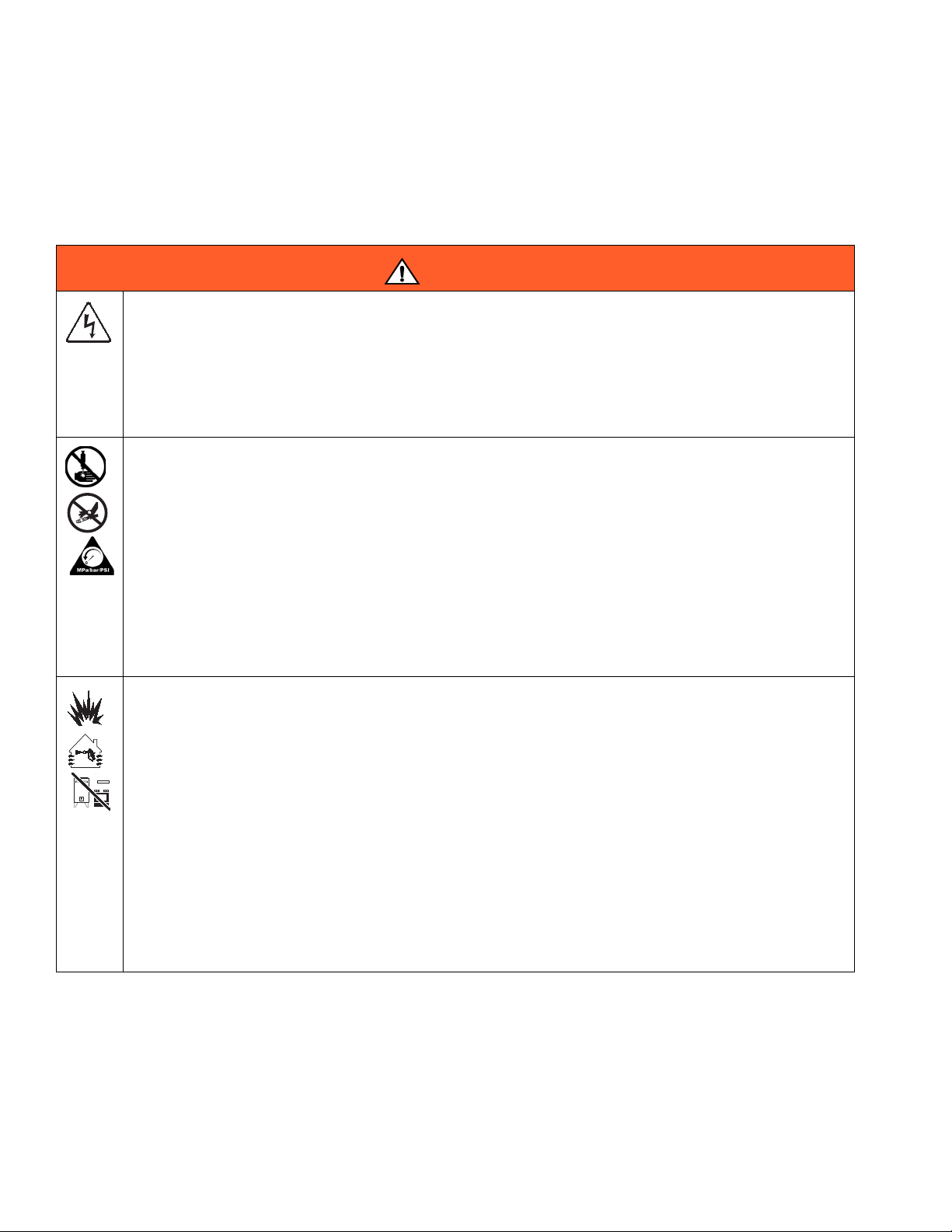
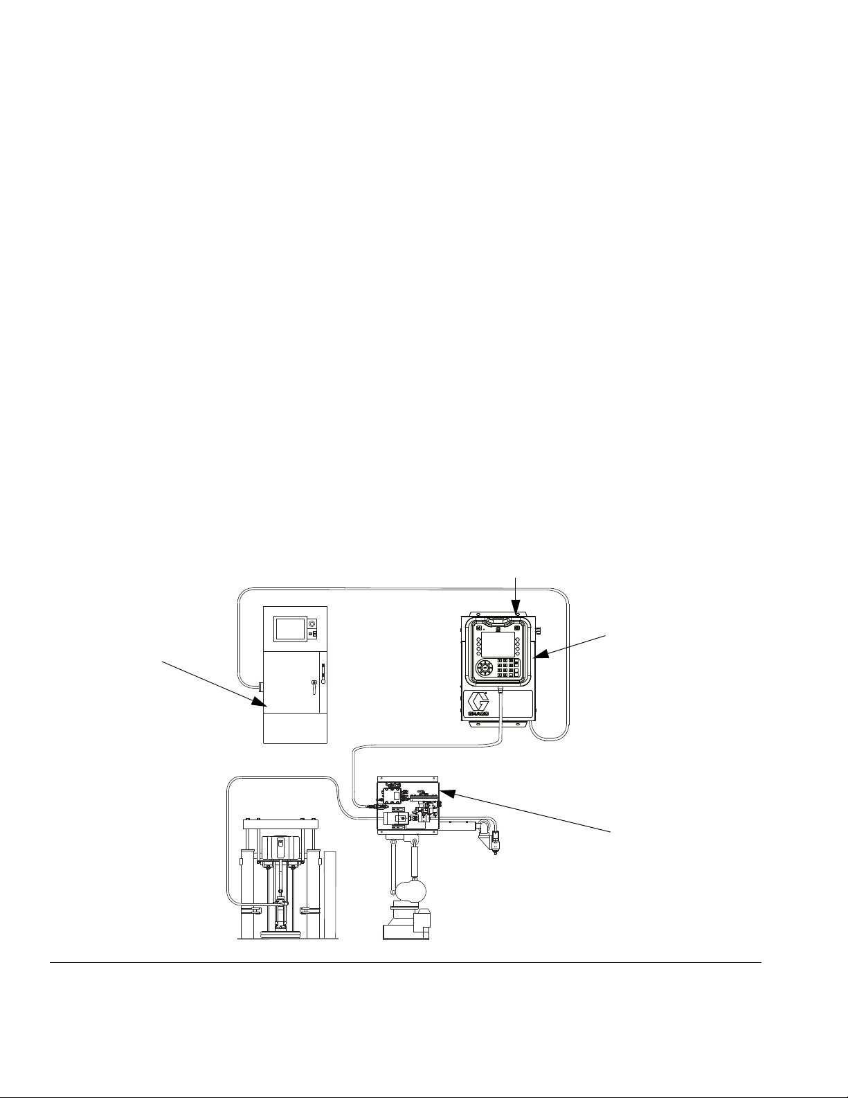
Typical Ambient System Installation
F
IG. 1: Typical Ambient System Installation
Key:
A *Control Center (User Interface)
B *Fluid Plate Assembly
C Applicator/Dispense Valve
DSealer Automation
E Automation Interface Cable
F *CAN Cable
G Fluid Supply System
H Fluid Supply Hose
J Automation Controller
K *Air Filter Assembly
* Included
8 313377L
Page 9
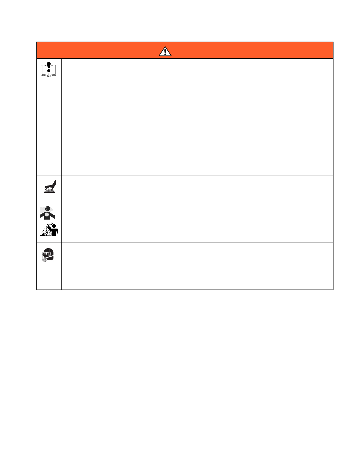
Typical Heated System Installation
AD
AC
AB*
AJ
AF*
AA*
AE
AH
AK
AM
AG
Air Supply
Drop Site
AL*
AN
Power
System Configurations
F
IG. 2: Typical Heated System Installation
Key:
AA *Control Center (User Interface)
AB *Fluid Plate Assembly
AC Applicator/Dispense Valve
AD Sealer Automation
AE Automation Interface Cable
AF *CAN Cable
AG Heated Fluid Supply System
AH Fluid Supply Hose
AJ Heat Control
AK Automation Controller
AL *Air Filter Assembly
AM RTD Cable
* Included
313377L 9
Page 10
Overview
Control Center
Fluid Plate
Assembly
Automation
Controller
Power
(User Interface)
Overview
System Overview
The PCF fluid metering system combines closed-loop
pressure control with the ability to change bead profiles
quickly. When used with the optional flow meter, the
module automatically adjusts for fluctuations in the operating environment, such as material viscosity, temperature, tip wear, and automation speed, while maintaining
the desired dispense rate. The module responds to
automation-supplied signals to provide an accurate and
consistent output flow based on a comparison of actual
to desired flow rates.
Typical Applications
• Bead dispensing
• Gasketing
• Seam sealing
• Hem flange
• Sound deadening
• Anti-flutter
• Body panel reinforcement
• Profile wrapping
• Cable filling
System Components
The diagram in FIG. 3 shows an example of the PCF
module and cables.
Control Center (User Interface)
The control center communicates with the PCF fluid
plate assembly to control fluid pressure and dispense
valve operation.
The control center receives input from the automation
controller, and uses these inputs to determine communication to the fluid plate assembly.
Fluid Plate Assembly
The fluid plate assembly contains components that control and monitor fluid dispensing.
F
IG. 3: PCF System Components
10 313377L
Page 11
Overview
U
R
P
T
S
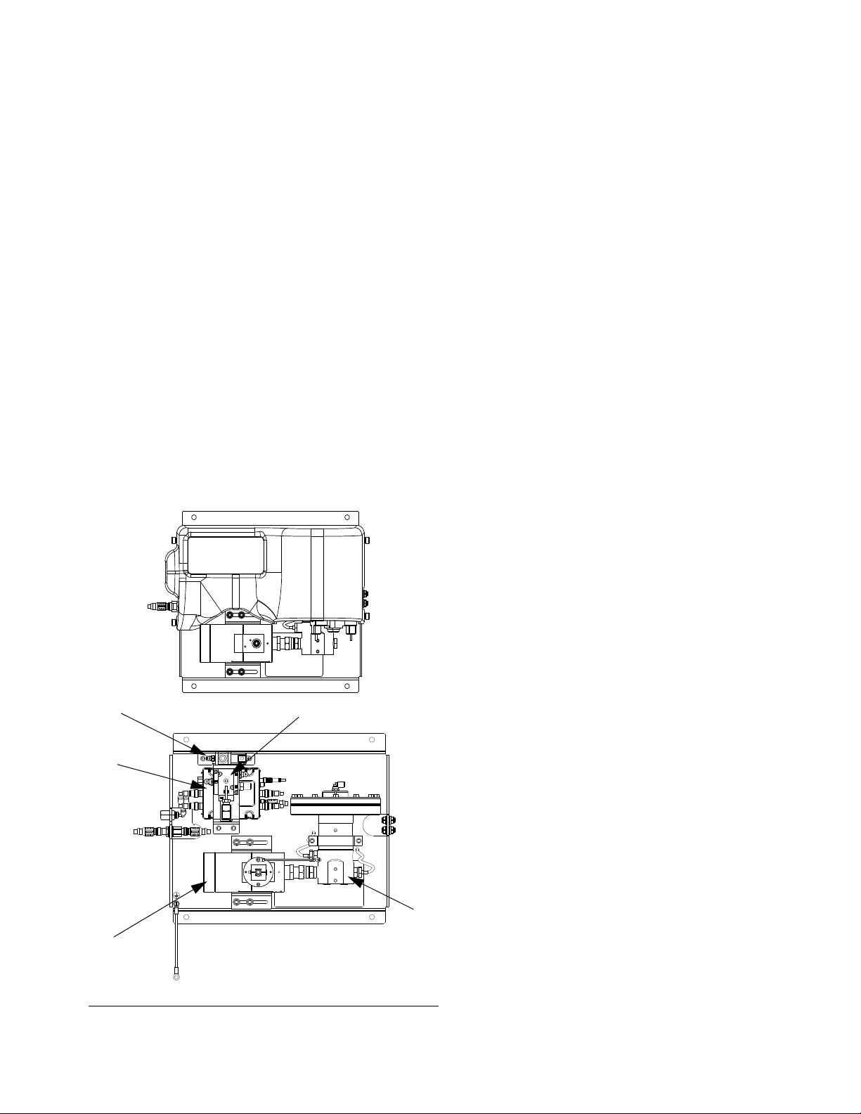
Fluid Plate Assembly Overview
Fluid Plate Components
The fluid plate assembly in FIG. 4 can be attached to an
automation arm or mounted on a pedestal. The main
components of the fluid plate assembly include:
• Fluid regulator (cartridge, ambient mastic, or heated
mastic) (P).
• Flow meter (R) (optional) precisely measures the
flow rate of fluid dispensed.
• Solenoid air valve (S) controls the dispense valve.
• V/P regulator (T) adjusts the air pressure to the fluid
regulator (P).
• Fluid Control Module (FCM) (U) receives pulse readings from the flow meter (R) and pressure readings
from the regulator. It also controls the fluid regulator
(P) and solenoid air valve (S).
The PCF fluid regulator is electrically controlled by the
PCF fluid control module. Consistent material flow is
assured by a closed-loop pressure or closed-loop flow
control design. The module responds to automation-supplied signals to provide an accurate and consistent output flow based on a comparison of actual to
desired flow rates. The fluid regulator uses air pressure
to control fluid pressure and to provide fast response to
electronic commands and ensure a precisely controlled,
continuous flow of material.
The fluid plate assembly is available in two versions:
ambient and heated.
Ambient Fluid Plate Assembly
There are four ambient versions available:
• cartridge regulator without a flow meter;
• ambient mastic regulator without a flow meter;
• cartridge regulator with a high resolution meter;
• ambient mastic regulator with a high resolution
meter.
Heated Fluid Plate Assembly
There are two heated versions available:
• heated mastic fluid regulator with a heated flow
meter,
• and a heated mastic fluid regulator without a
flow meter.
F
IG. 4: Fluid Plate Components
313377L 11
Page 12
Overview
3
4
5
CAN
Connectors
TI12337A
TI12336A
6
7
Status LEDs
1
2
Fluid Regulator
There are three fluid regulator options:
•cartridge
• ambient mastic
• heated mastic
All of the fluid regulator options use air pressure to control fluid pressure, provide fast response to electronic
commands, and ensure a precisely controlled, continuous flow of material.
Cartridge
The cartridge regulator (244734) is ideal for low to
medium viscosity sealants and adhesives.
Ambient Mastic
The ambient mastic regulator (246642) is ideal for
medium to high viscosity sealants and adhesives.
Heated Mastic
The heated mastic regulator (246643) is ideal for low to
high viscosity warm-melt and hot-melt sealants or adhesives.
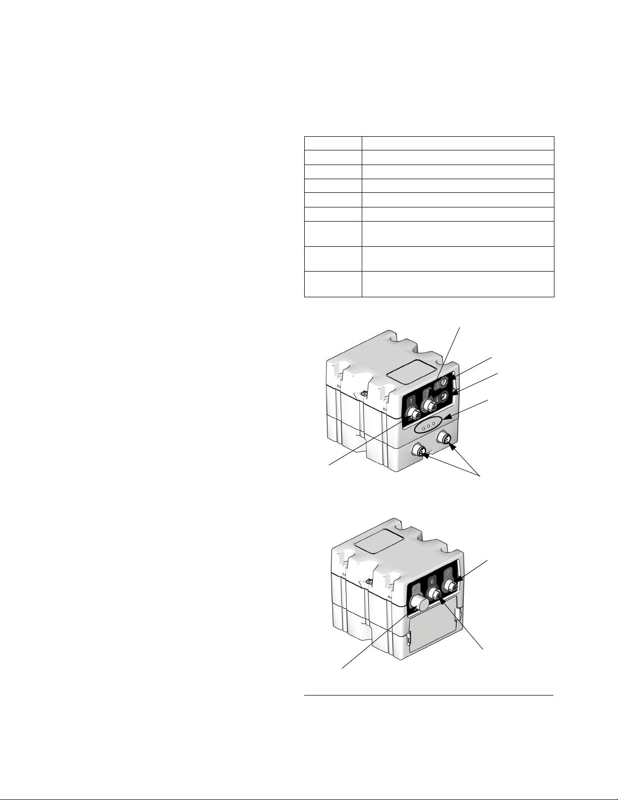
Fluid Control Module (FCM)
NOTE: See LED Diagnostic Information, page 54, for
signal definitions.
Table 1: FCM Sensor Connections
Connection Sensor Description
1 Dispense solenoid
2Flow meter
3 Outlet pressure sensor (heated systems only)
4V/P
5 Command cable (optional accessory kit)
6 Inlet pressure sensor (non-heated systems
only)
7 Outlet pressure sensor (non-heated systems
only)
CAN
Connectors
FIG. 5: FCM Sensor Connections
12 313377L
Page 13
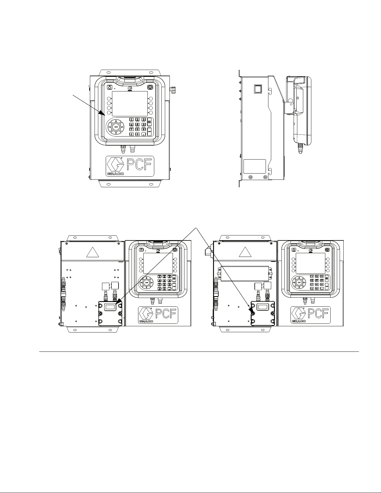
Control Center Assembly Overview
Front View
Side View
Open View
ADM
Gateway Module
(24 Vdc Assembly)
(100-240 Vac Assembly)
Overview
F
IG. 6: Control Center Components
The control center includes the following components:
• Advanced Display Module (ADM) with USB; see
page 14 for details.
• USB enables users to download job, error, and data
logs; save and restore system settings; and customize the language.
• 24 Vdc and 100-240 Vac customer-wired options
available.
• Gateway Module, which includes the following five
options:
• Discrete
• DeviceNet
• EtherNet/IP
•PROFIBUS
• PROFINET
313377L 13
Page 14
Overview
TI12362a
BA
BB
BC
BE
BH
BG
BF
BD
r_24E451_3B9900_1a
BJ
BR
BP
BN
BM
BL
BK
BS
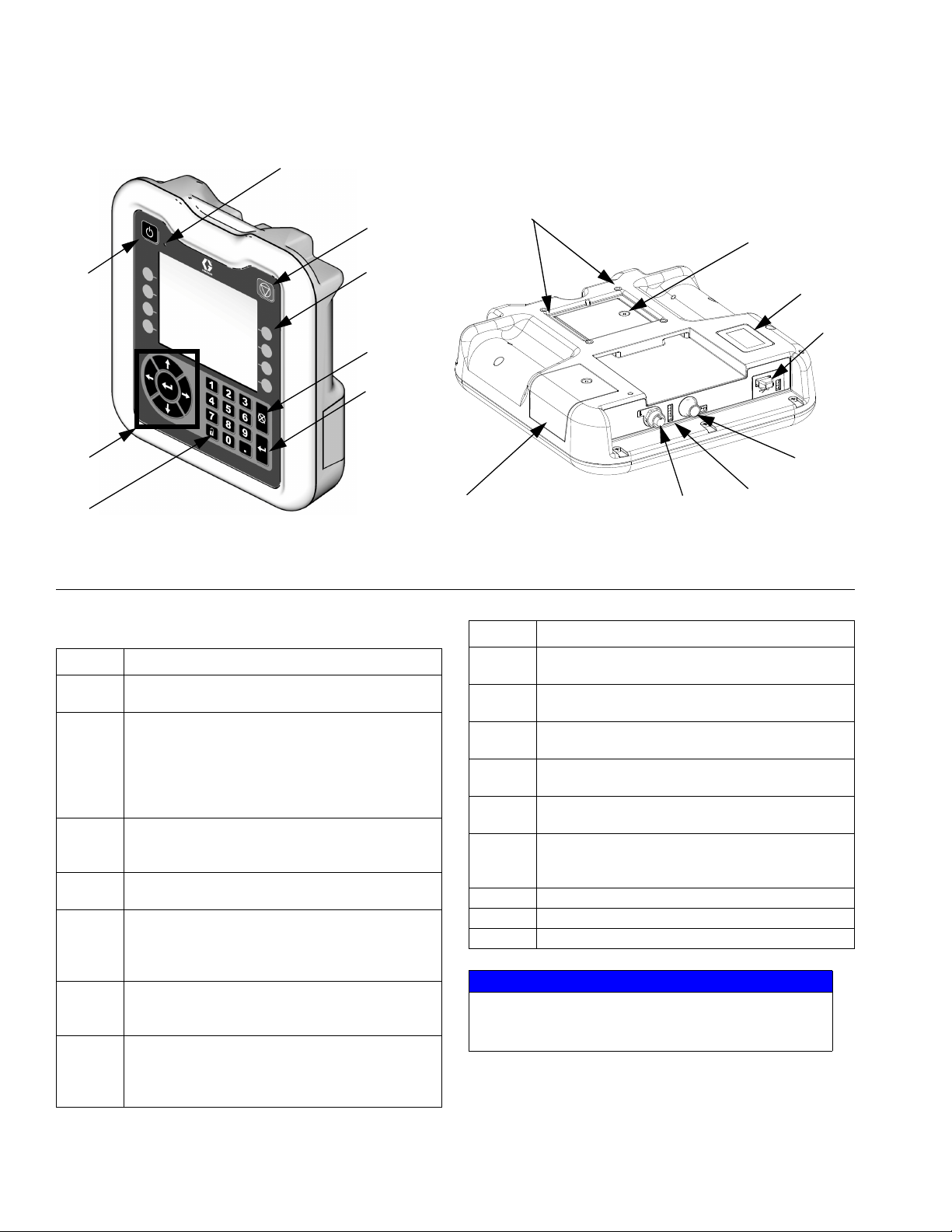
Advanced Display Module (ADM)
F
IG. 7: Advanced Display Module Component Identification
KEY:
Callout Function
BA Power On/Off Button
Enables/disables system.
BB System Status Indicator LED
Displays system status. Green LED indicates the
system is active. Orange LED indicates the system is off. Solid LEDs indicate the system is in
Run mode. Flashing LEDs indicate the system is
in Setup mode.
BC Stop Button
Stops all system processes. However, it is not a
safety or emergency stop.
BD Soft Keys
Functions vary depending on the screen.
BE Cancel Button
Clears system errors and cancels a selection or
number entry while in the process of entering a
number or making a selection.
BF Enter Button
Acknowledge changing a value or making a
selection.
BG Lock/Setup
Toggle between run and setup screens. If setup
screens are password protected, button toggles
between run and password entry screens.
Callout Function
BH Navigation Buttons
Navigate within a screen or to a new screen.
BJ Flat Panel Mount
Mounts to control center bracket (optional).
BK Model Number Tag
Model number.
BL USB Module Interface
USB port and USB indicator LEDs
BM CAN Connector
Power connection.
BN Module Status LEDs
BP Battery Cover
BR Token Access Cover
BS Digital I/O Port for Light Tower
See LED Diagnostic Information, page 54, for
signal definitions.
NOTICE
To prevent damage to the soft key buttons, do not
press the buttons with sharp objects such as pens,
plastic cards, or fingernails.
14 313377L
Page 15
Gateway Module
TI11985A
TI11814A
TI11815A
TI11816A
CA
CD
See Gateway Module Connector Table
Gateway Module Connectors Table
CB
PROFINET or EtherNet/IP
DeviceNet
PROFIBUS
CE
TI11972A
CF
CH
Front Back
Discrete
CC
CG
CC
CC
Overview
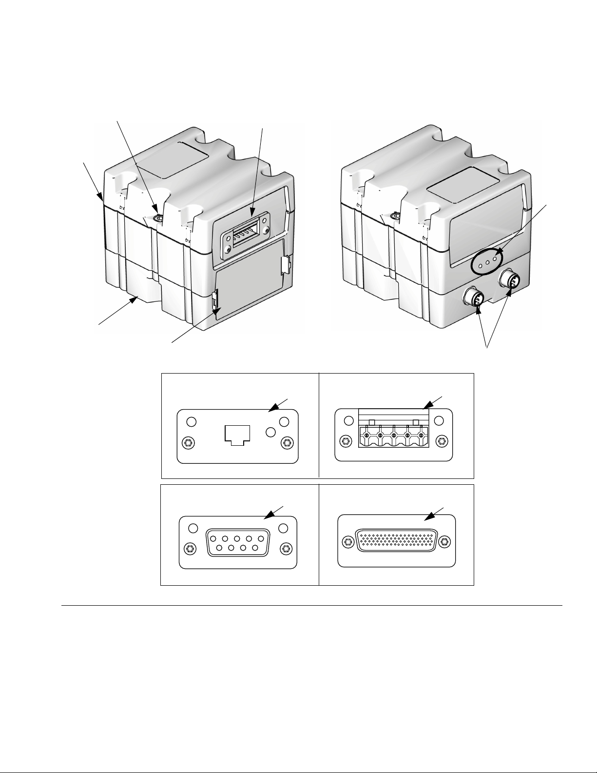
F
IG. 8: Gateway Module Components
Key:
CA Gateway Module
CB Base
CC Fieldbus Connector (see Appendix C - Communi-
cations Gateway Module (CGM) Connection
Details, page 105, for more information)
CD Module Connection Screws
CF Module Status LEDs (see LED Diagnostic Infor-
mation, page 54)
CG D-Subminiature (D-Sub) Connector (see Appendix
CH CAN Connectors
B - Discrete Gateway Module (DGM) Connection
Details, page 98, for pinout details)
CE Access Cover
313377L 15
Page 16

Installation
Installation
Before Installation
• Have all system and component documentation
available during installation.
• See component manuals for specific data on component requirements. Data presented here applies to
the PCF assemblies only.
• Be sure all accessories are adequately sized and
pressure-rated to meet system requirements.
• Use the PCF control center only with the PCF fluid
plate assembly.
Overview
The basic steps to install a PCF system are shown
below. See the separate component manuals for
detailed information.
NOTICE
To avoid damaging the PCF system, use at least two
people to lift, move, or disconnect the system. The
system is too heavy for one person to lift or move.
Installation Steps
1. Mount control center.
2. Connect and ground control center.
3. Mount fluid plate assembly.
4. Ground fluid plate assembly.
5. Check ground continuity.
6. Connect fluid lines between fluid module and applicator. Connect fluid supply line and air supply to
module.
7. Plumb filter assembly near air drop site that will be
used for fluid plate assembly.
8. Connect other fluid and air lines to additional system
components as instructed in their manuals.
9. Install cable assemblies.
10. Install Gateway interface.
16 313377L
Page 17
Installation
A
B
C
D
Install Control Center
Mount
Ensure the following criteria are met before mounting
the PCF control center:
• Select a location for the control center that allows
adequate space for installation, service, and use of
the equipment.
• For best viewing, the ADM should be 60-64 in.
(152-163 cm) from the floor.
• Ensure there is sufficient clearance around the control unit to run cables to other components.
• Ensure there is safe and easy access to an appropriate electrical power source. The National Electric
Code requires 3 ft. (0.91 m) of open space in front of
the control center.
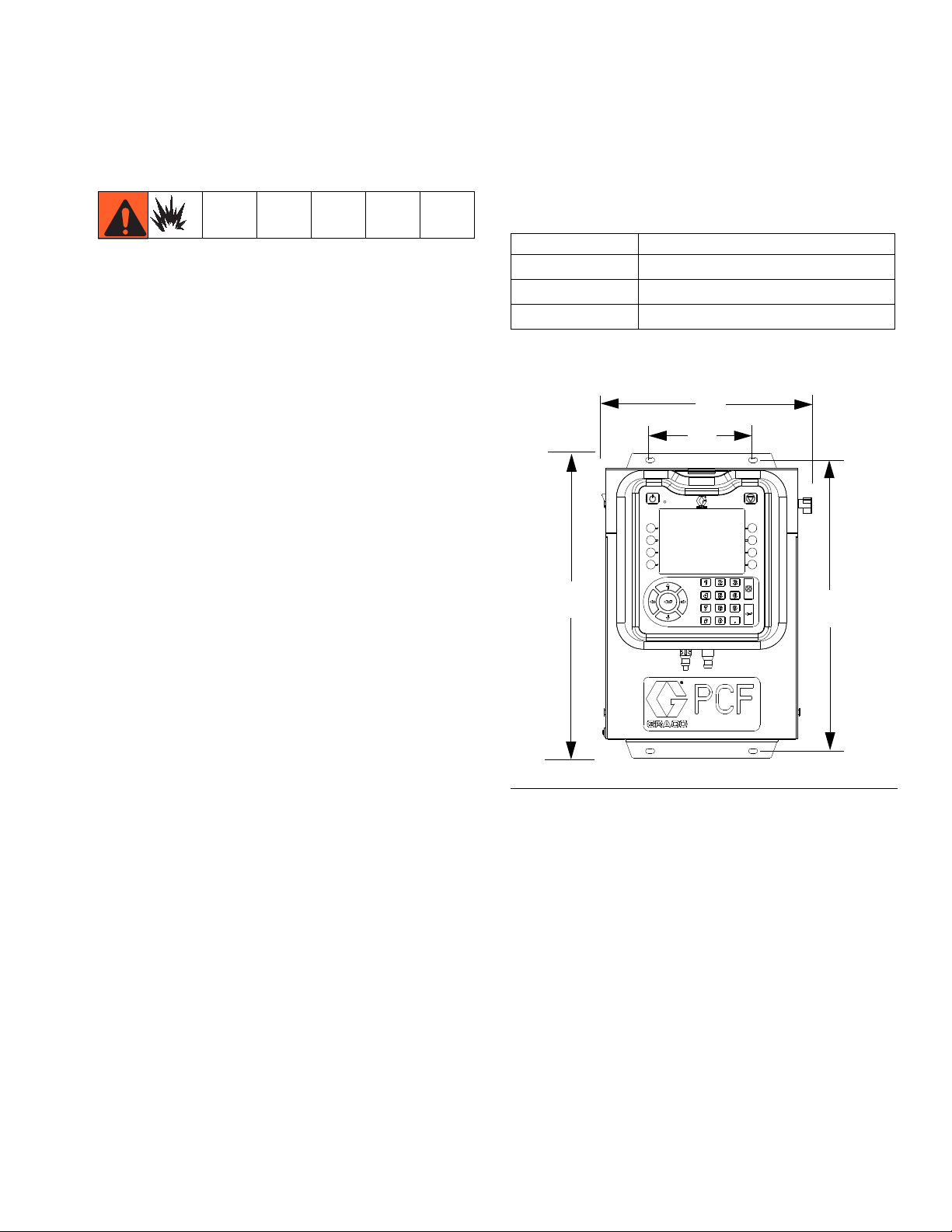
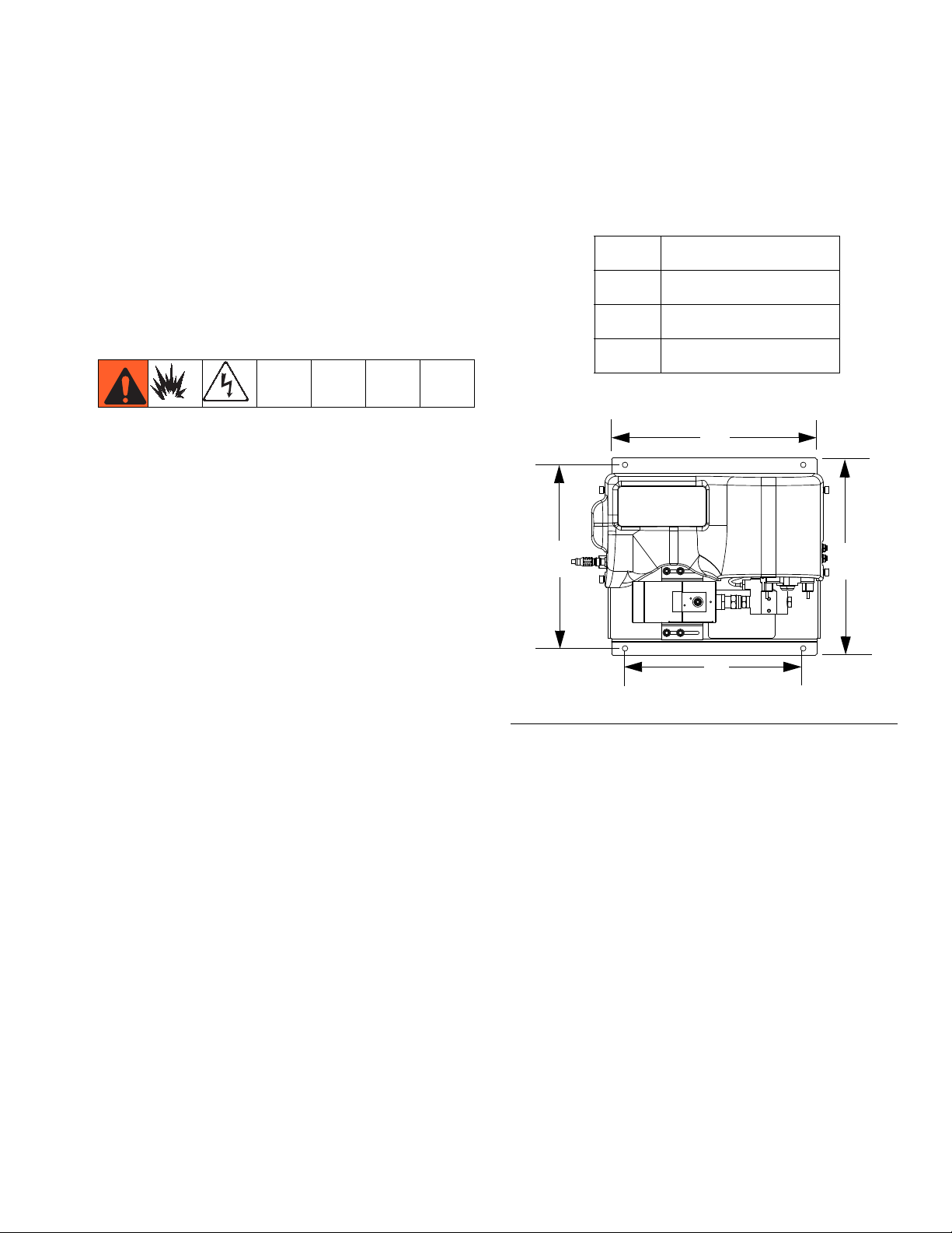
Secure the control center with appropriate size bolts
through the 0.27 in. (7 mm) diameter holes in the mounting tabs. See the mounting dimensions in Table 2 and
F
IG. 9.
Table 2: Control Center Assembly Measurement
A
B
C
D
10.50 in. (267 mm)
5.75 in. (146 mm)
17.00 in. (432 mm)
16.25 in. (413 mm)
• Ensure there is easy access to the power switch.
• Ensure the mounting surface can support the weight
of the control center and the cables attached to it.
F
IG. 9: Control Center Dimensions
313377L 17
Page 18
Installation
+
-
Ground
Ground
N
L
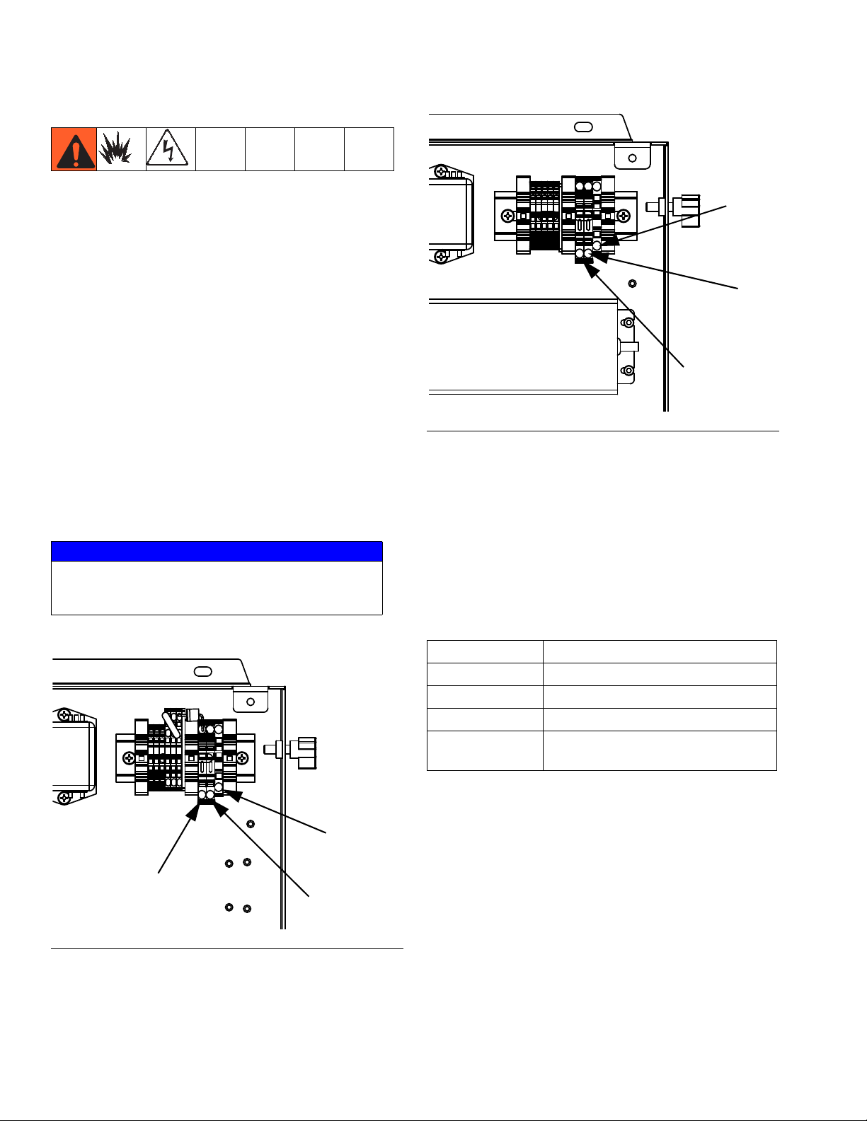
Electrical Connections
Follow these precautions when grounding, connecting
cables, connecting to a power source or making other
electrical connections.
To reduce the risk of fire, explosion, or electric shock:
• The control center must be electrically connected to
a true earth ground; the ground in the electrical system may not be sufficient.
• All wires used for grounding must be 18 AWG minimum.
• A qualified electrician must complete all grounding
and wiring connections.
• For 24 Vdc wiring refer to F
• For 100-240 Vac wiring refer to F
• Refer to your local code for the requirements for a
“true earth ground” in your area.
NOTICE
If power and grounding connections are not done
properly, the equipment will be damaged and the
warranty voided.
IG. 10.
IG. 11.
FIG. 11: 100-240 Vac Wiring
Connect Light Tower Accessory
1. Order the 255468 Light Tower Accessory as a diagnostic indicator for the PCF system.
2. Connect the cable from the light tower to the digital
I/O port (BS) on the ADM.
See Table 3 for a description of light tower signals.
Table 3: Light Tower Signals
Signal Description
Green No errors.
Yellow An advisory exists.
Red flashing A deviation exists.
Red solid An alarm exists and the system is
shut down.
NOTE: See Errors, page 55, for error definitions.
F
IG. 10: 24 Vdc Wiring
18 313377L
Page 19
Installation
A
B
C
D
Install Fluid Plate Assembly
To install the PCF fluid plate assembly:
• Mount the fluid plate assembly.
• Ground fluid plate assembly.
• Connect the fluid plate assembly to the control cen-
ter.
• Connect fluid lines and cables.
Mount
Before Mounting Assembly
• See component manuals for specific information on
component requirements. Information presented
here pertains to the PCF fluid plate assembly only.
• Have all system and subassembly documentation
available during installation.
2. Mount and secure the fluid plate assembly to the
automation unit (or other mounting surface) with
appropriate size bolts through the 0.397 in. (10 mm)
diameter holes in the base plate. See the mounting
dimensions in Table 4 and F
Table 4: Fluid Plate Assembly Measurement
A
B
C
D
IG. 12.
16.5 in. (419 mm)
14.0 in. (356 mm)
14.4 in. (366 mm)
13.4 in. (340 mm)
• Be sure all accessories are adequately sized and
pressure-rated to meet the system's requirements.
• Use only the Graco PCF fluid plate assembly with
the Graco PCF control center.
Mount Assembly
1. Select a location for the fluid plate assembly. Keep
the following in mind:
• Allow sufficient space for installing the equipment.
• Make sure all fluid lines, cables and hoses easily reach the components to which they will be
connected.
• Make sure the fluid plate assembly allows the
automation unit to move freely along all axis.
• Make sure the fluid plate assembly provides
easy access for servicing its components.
IG. 12: Fluid Plate Assembly Dimensions
F
313377L 19
Page 20
Installation
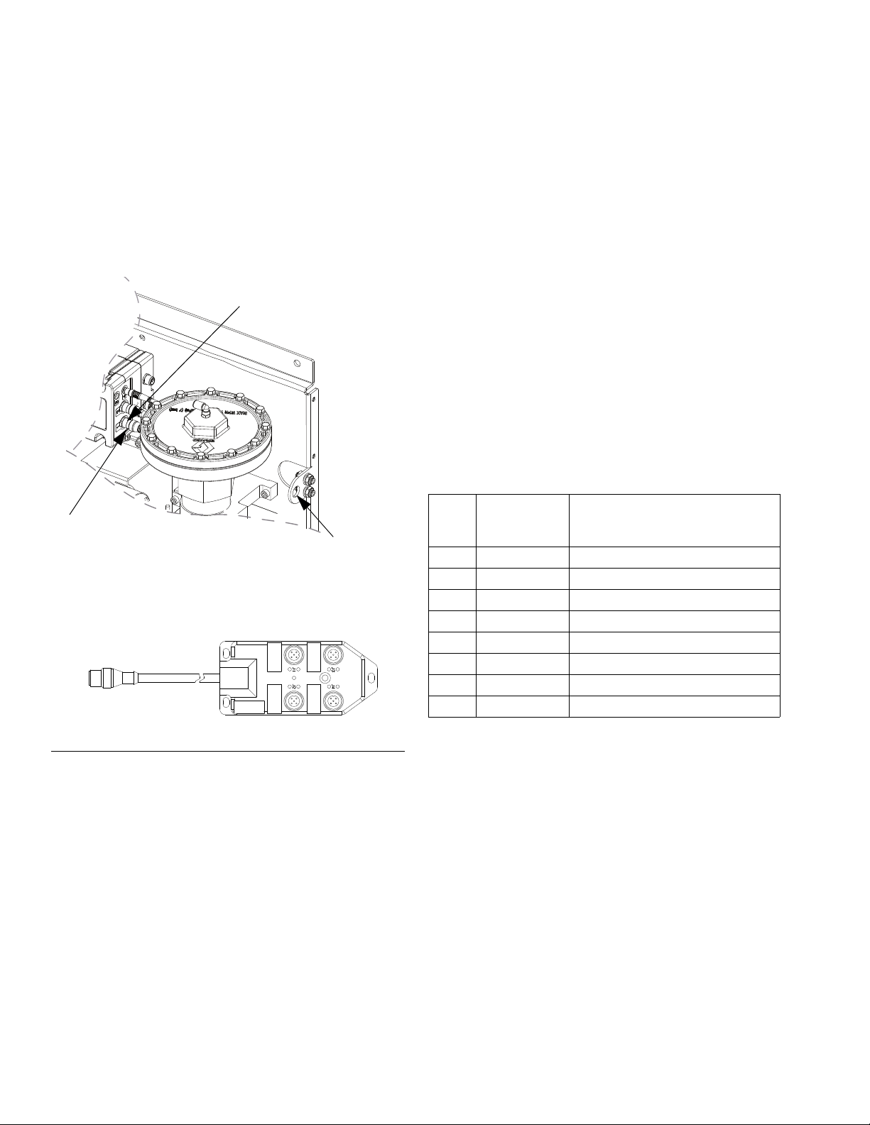
GCA Cable
Splitter Assembly
Hole for bulkhead fitting
Connection 1
Mount Four-Valve Breakout Kit 24B693
Follow this procedure if using the four-valve breakout
kit.
1. Remove the existing dispense solenoid and cable
from the fluid plate.
2. Install bulkhead fitting (included in the kit) into the
empty hole on the fluid plate.
NOTE: Up to three additional dispense valves can
be connected to the dispense valve splitter assembly. For each additional dispense valve required
order one dispense valve (258334) and one solenoid
cable (121806).
6. Mount splitter assembly and dispense valves, and
connect air lines as necessary for application.
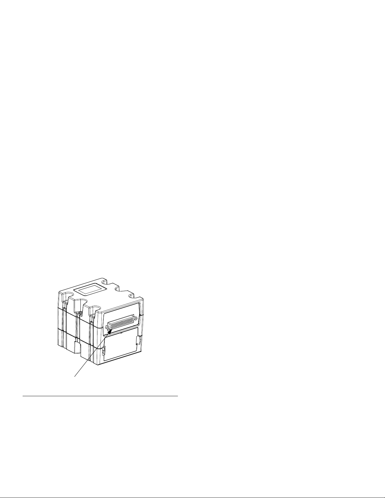
Install Command Cable Kit 24B694
Follow this procedure if using the command cable kit.
1. Install bulkhead fitting (included in the kit) into the
empty hole on the fluid plate. See F
IG. 13.
2. Connect one end of the extension cable (included in
the kit) to connection 5 on the FCM and the other
end of the cable to the bulkhead fitting.
3. Connect command cable to bulkhead fitting and
wire to automation controller per the following pinout
table.
FCM
Port
Pin #
1 White Command voltage (0-10 Vdc)
2 Brown No connection
3 Green Dispense trigger (*sourcing input)
4 Yellow No connection
5 Gray Dispense trigger ground
6 Pink No connection
7 Blue Command signal ground
8 Red No connection
Command
Cable Wire
Color Function
F
IG. 13: Mount Breakout Kit
3. Connect one end of the extension cable (included in
4. Connect the splitter assembly to the bulkhead fit-
5. Connect the dispense valve cable(s) to the connec-
20 313377L
the kit) to connection 1 on the FCM and the other
end of the cable to the bulkhead fitting.
ting.
tions on the splitter assembly.
NOTE: Command cable inputs are not isolated from
PCF 24 Vdc power.
* To turn on the dispense trigger, connect pin 3 (dis-
pense trigger) to pin 5 (dispense trigger ground).
Page 21
Installation
Ground
NOTICE
If power and grounding connections are not done
properly, the equipment will be damaged and the
warranty voided.
Ground the fluid plate assembly as instructed here and
in the individual component manuals. Make sure the
fluid plate assembly and its components are installed
correctly to ensure proper grounding.
Air and Fluid Hoses
For static dissipation, use only electrically conductive
hoses or ground the applicator / dispense valves.
Dispense Valve
Follow the grounding instructions in the dispense valve
manual.
• Air must be clean and dry, between 60-120 psi
(0.41-0.82 MPa, 4.14-8.27 bar). Flush air line before
plumbing in air filter assembly (234967). Plumb in air
filter assembly near air drop site (upstream of fluid
plate module). Adding an air regulator to this line will
provide more consistent dispense valve response
times.
• Connect an air supply line to the 1/4 npt inlet port on
the fluid module(s) air supply inlet.
• Connect 5/32 in. or 4 mm OD air lines from the applicator's solenoid valve to the applicator. Plug any
unused solenoid ports.
NOTE: To maximize system performance keep the
dispense hose length and ID as small as the application will allow.
Connect Fluid and Air Lines
NOTICE
Route all fluid and air lines carefully. Avoid pinching
and premature wear due to excessive flexing or rubbing. Hose life is directly related to how well they are
supported.
Follow the instructions in your separate component
manuals to connect air and fluid lines. The following are
only general guidelines.
• The PCF fluid plate assembly should be installed on
the automation unit or in another appropriate place,
as close as practical to the dispense valve.
• Connect a fluid line between the fluid plate outlet and
the dispense valve. Smaller diameter and shorter
fluid lines (hoses) will provide better fluid system
response.
• Connect a fluid line to the flow meter fluid inlet or to
the regulator inlet if your system does not have a
flow meter.
313377L 21
Page 22
Installation
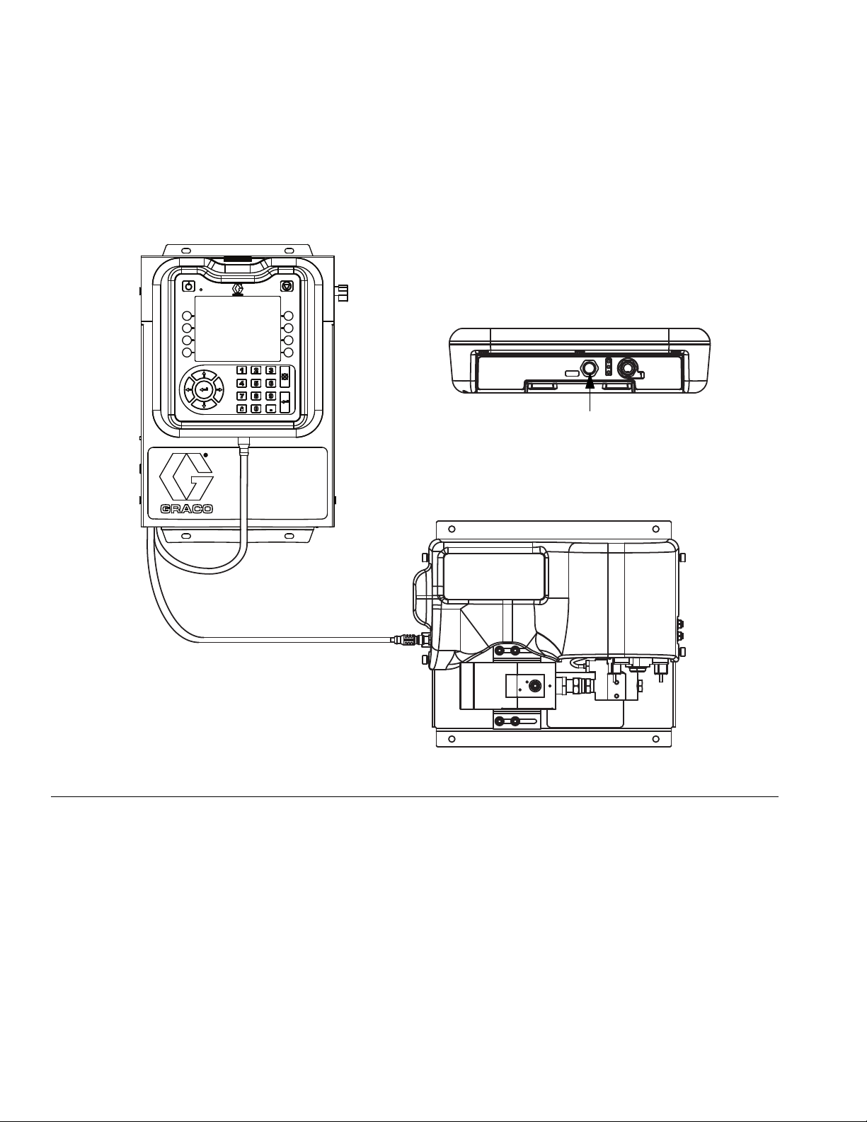
From Control Center
Power to FCM
Power to ADM
Install Cable Assemblies
NOTE: To prevent system errors, only connect
cables with the power off.
1. Connect the CAN cable from the control center to
the fluid plate assembly.
2. Connect the Gateway module to the automation
controller.
3. Connect power cable from power source to control
center.
F
IG. 14: Cable Installation Diagram
22 313377L
Page 23

Install Gateway Module Interface
Installation
Fieldbus Communications Gateway Module
Module Description
The Communications Gateway Module (CGM) provides
a control link between the PCF system and a selected
fieldbus. This provides the means for remote monitoring
and control by external automation systems.
See Automation Control (Normal) Operation, page
37, for details on controlling the PCF system through the
Gateway module.
Data Exchange
Data is available by block transfer, cyclic transfer,
change of state triggered, and explicit access to individual attributes as defined by the fieldbus specification.
Refer to Appendix C - Communications Gateway
Module (CGM) Connection Details, page 111, for
details about PCF/fieldbus data map.
NOTE: The following system network configuration
files are available at www.graco.com
• EDS file: DeviceNet or EtherNet/IP fieldbus networks
• GSD file: PROFIBUS fieldbus networks
• SDML: PROFINET fieldbus networks
CGM Status LED Signals
Signal Description
Green on System is powered up
Yellow Internal communication in progress
Red
Solid
*Red
(7 flashes)
*The red LED (CF) will flash a code, pause, then repeat.
CGM hardware failure
Data map load failure
Incorrect data map for fieldbus type
No data map loaded
Installation
NOTE: The following installation instructions
assume the person implementing the PFC fieldbus
connection fully comprehends the fieldbus being
used. Ensure the installer understands the automation controller communication architecture and the
fieldbus being used.
1. Install interface cables between the PCF system
and the automation controller per the fieldbus standards. Refer to Appendix C - Communications
Gateway Module (CGM) Connection Details,
page 105, for details.
2. Turn on system power. Navigate to the Gateway
setup screens, and ensure the PCF standard data
map is installed. Refer to Appendix A - Advanced
Display Module (ADM), page 85, for details about
the data map.
3. Set the PCF Gateway configuration values as
required to interface with automation controller.
Refer to Appendix A - Advanced Display Module
(ADM), page 85, for details about the configuration
settings.
4. Retrieve the appropriate fieldbus configuration file
for the fieldbus being used from www.graco.com.
5. Install the configuration file on the automation controller (fieldbus master). Configure it for communication with the PCF Gateway (fieldbus slave).
6. Establish communication between the automation
controller and the PCF Gateway to confirm the successful configuration of the hardware and data.
NOTE: Use the control center run screen for troubleshooting fieldbus data communication problems.
Refer to Appendix A - Advanced Display Module
(ADM), page 85, for details. Also, use the status indicators on the PCF Gateway module for fieldbus status information. Refer to Appendix C Communications Gateway Module (CGM) Connection Details, page 105, for details.
313377L 23
Page 24
Installation
r_24B681_2B9904_2b
CG
Discrete Gateway Module
Module Description
The Discrete Gateway Module (DGM) provides a control
link between the PCF system and an automation controller through discrete input and output connections.
This provides the means for remote monitoring and control by external automation systems.
See Automation Control (Normal) Operation, page
37, for details on controlling the PCF system through the
Gateway module.
Connect D-Sub Cable
The DGM provides all I/O through the D-Sub cable.
Graco offers two options for connecting a D-Sub cable
to the D-Sub connector (CG). Both options are accessories and must be ordered separately.
• D-Sub to flying leads cable (123793). See
Appendix B - Discrete Gateway Module
(DGM) Connection Details, page 98, for
details and cable interface signals.
• D-Sub cable (123972) and 78-pin breakout
board (123783). See Appendix B - Discrete
Gateway Module (DGM) Connection Details,
page 98, for details and pin assignments.
F
IG. 15: Connect D-Sub Cable
DGM Status LED Signals
See LED Diagnostic Information, page 54, for signal
definitions.
24 313377L
Page 25

System Setup
System Setup
Configure Control Settings (
page 26)
Configure Mode Settings (
page 27)
Configure Delay Settings (
page 28)
Configure Flow Meter
Settings (
page 28)
Configure Pressure Loop
Settings (
page 29)
Adjust Pressure Sensors (
page 29)
Configure Errors (
page 30)
Setup Styles (
page 31)
Setup Maintenance
Schedule/Parameters (
page 31)
Configure Gateway
Settings (
page 31)
Configure Advanced
Settings (
page 31)
End System Setup
Overview
The PCF system compensates for temperature, flow, or
pressure fluctuations. However, if there is a hardware
change on the supply system or the dispense material is
changed, the PCF system must be setup again.
After material is loaded into the supply system, set up
the PCF system using the Setup screens. F
the major system setup steps. The following subsections provide instructions to complete each setup step.
Once these steps are complete the module is ready for
operation.
NOTE: See the Advanced Display Module (ADM)
section, page 14, and Appendix A - Advanced Display Module (ADM), page 85, for detailed operating
instructions for the display keypad and each screen.
IG. 16 shows
System Setup
F
IG. 16
313377L 25
Page 26
System Setup
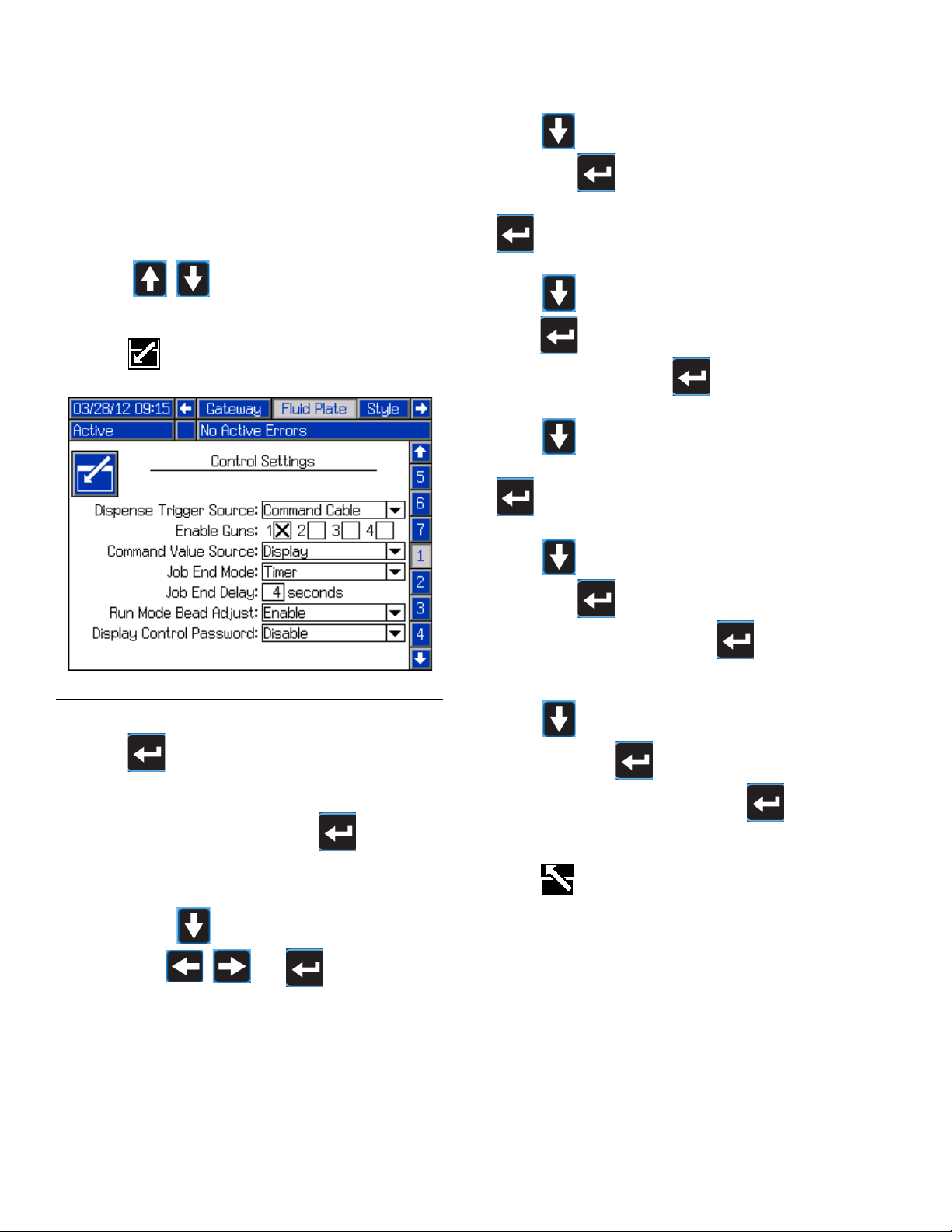
Configure Control Settings
Set the controls for the dispense source, how dispense
commands are sent, and job settings.
1. With the system in setup mode, navigate to the Fluid
Plate set of screens.
2. Press to scroll to the Control Settings
screen (screen 1).
3. Press to access the fields to make changes.
6. Press to move to the Command Value Source
field. Press to open the drop-down list, and
select Gateway, Command Cable, or Display. Press
to enter the value.
7. Press to move to the Job End Mode field.
Press to open the drop-down list, and select
Timer or Gateway. Press to enter the value.
8. Press to move to the Job End Delay field.
Enter the desired delay time (in seconds). Press
to enter the value.
9. Press to move to the Run Mode Bead Adjust
F
IG. 17
4. Press to open the Dispense Trigger Source
drop-down list, and select Gateway, Command
Cable, or Combined. If Command Cable is selected,
users can enable the guns. Press to finalize
the selection.
5. If the dispense trigger source is set to Command
Cable, press to move to the Enable Guns
field. Press and to enable guns.
field. Press to open the drop-down list, and
select Enable or Disable. Press to enter the
value.
10. Press to move to the Display Control Pass-
word field. Press to open the drop-down list,
and select Enable or Disable. Press to enter
the value.
11. Press to exit edit mode.
26 313377L
Page 27
System Setup
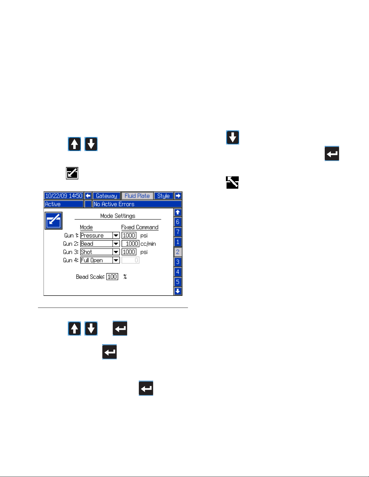
Configure Mode Settings
Set gun commands, including the dispense mode (pressure, bead, shot, or full open) and flow rate or pressure
for each gun. The bead scale is also adjustable from the
Mode Settings screen.
NOTE: For a description of each dispense mode,
see Home Screen 1 - Fluid Plate, page 95.
1. With the system in setup mode, navigate to the Fluid
Plate set of screens.
2. Press to scroll to the Mode Settings
screen (screen 2).
3. Press to access the fields to make changes.
NOTE: The ability to dispense from multiple guns
simultaneously is only allowed in either of the following scenarios.
• Each gun is set to Pressure mode and has
identical Fixed Command values.
• Each gun is set to Full Open mode.
Attempting to dispense from multiple guns simultaneously using any other combination will cause an
Incompatible Guns Settings alarm.
6. Press to move to the Bead Scale field. Enter a
scale value between 50% and 150%. Press to
enter the value.
7. Press to exit edit mode.
F
IG. 18
4. Press and to set the mode for
each gun that will be used to Pressure, Bead, Shot,
or Full Open. Press to enter each selection.
5. Use the four arrow buttons to navigate to each
Fixed Command field. Enter the desired value for
each gun that will be used. Press to enter
each value.
313377L 27
Page 28
System Setup
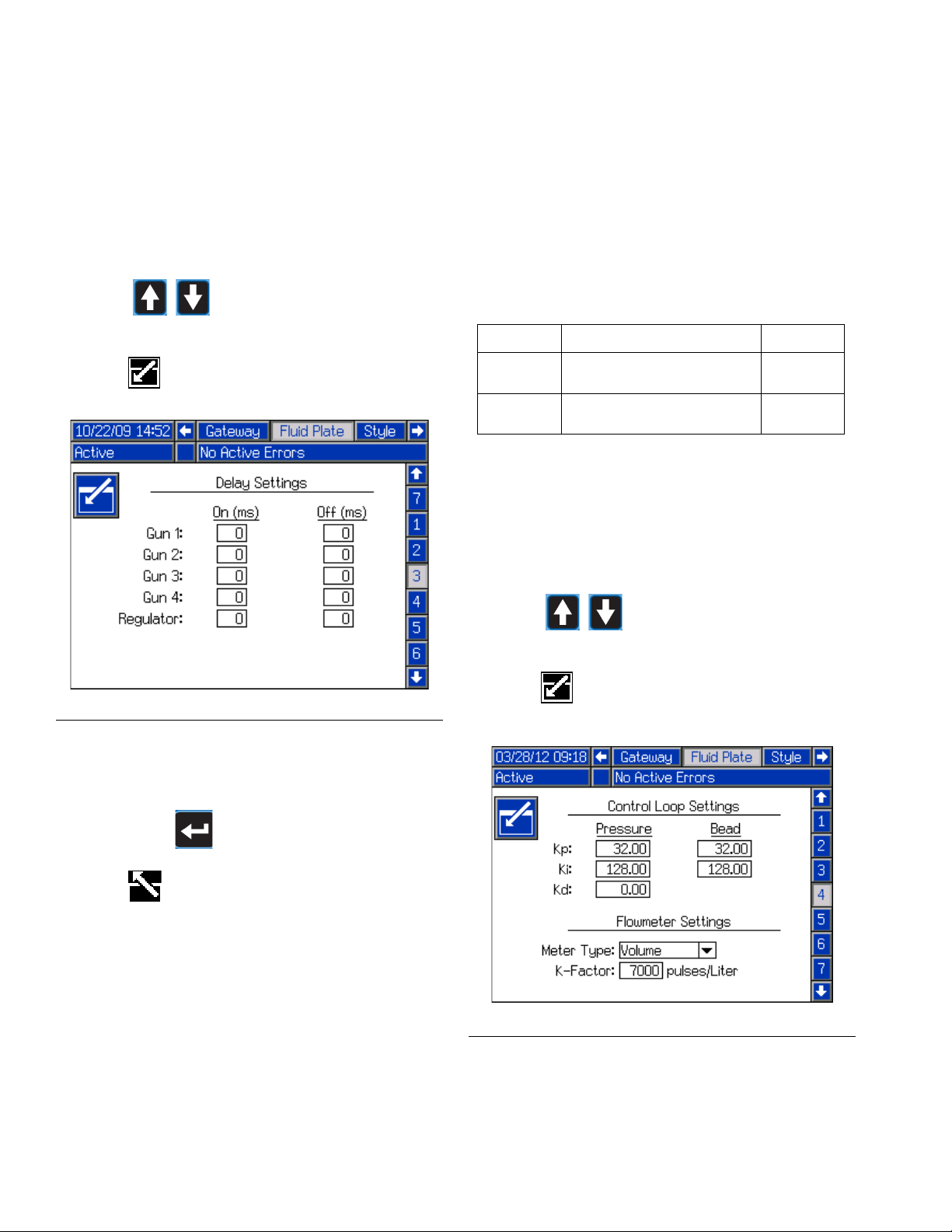
Configure Delay Settings
Set on and off delays (in milliseconds) for each gun and
the regulator. For an explanation of the on and off
delays, refer to the On/Off Delays section on page 32.
1. With the system in setup mode, navigate to the Fluid
Plate set of screens.
2. Press to scroll to the Delay Settings
screen (screen 3).
3. Press to access the fields to make changes.
Configure Flow Meter Settings
The accuracy of the PCF volume reporting depends on
precise adjustment of the K-factor(s). The fluid plate
uses the K-factor(s) to calculate the volume dispensed.
If the set value is not correct, the system still delivers
repeatable flow rates; however, the reported value may
not be correct. See Verify Flow Meter Calibration,
page 35, for additional K-factor information.
Table 5: Flow Meter K-Factors
Part Description K-Factor
246652 High Resolution Helical
Gear Meter
246340 Heated Helical Gear
Meter
Set Flow Meter K-Factor
NOTE: In systems without a flow meter, the flow
meter settings will be grayed out.
1. With the system in setup mode, navigate to the Fluid
Plate set of screens.
7000
3500
F
IG. 19
4. Use the four arrow buttons to navigate to each On
and Off field. Enter a desired delay value (in milliseconds) for each gun that will be used and the reg-
ulator. Press to enter each value.
5. Press to exit edit mode.
2. Press to scroll to the Flowmeter Set-
tings screen (screen 4).
3. Press to access the fields to make changes.
F
IG. 20
28 313377L
Page 29
System Setup
4. Press to open the Meter Type drop-down list,
and select the meter type used by the system.
Select Volume for volumetric flow meters or Mass
for mass flow meters. Press to enter the
selection.
5. Press to move to the K-Factor field. Key in the
K-factor value. See Table 5: Flow Meter K-Factors
for values. Press to enter the value.
6. Press to exit edit mode.
NOTE: If necessary, verify flow meter calibration.
See Verify Flow Meter Calibration, page 35, for
instructions.
Configure Control Loop Settings
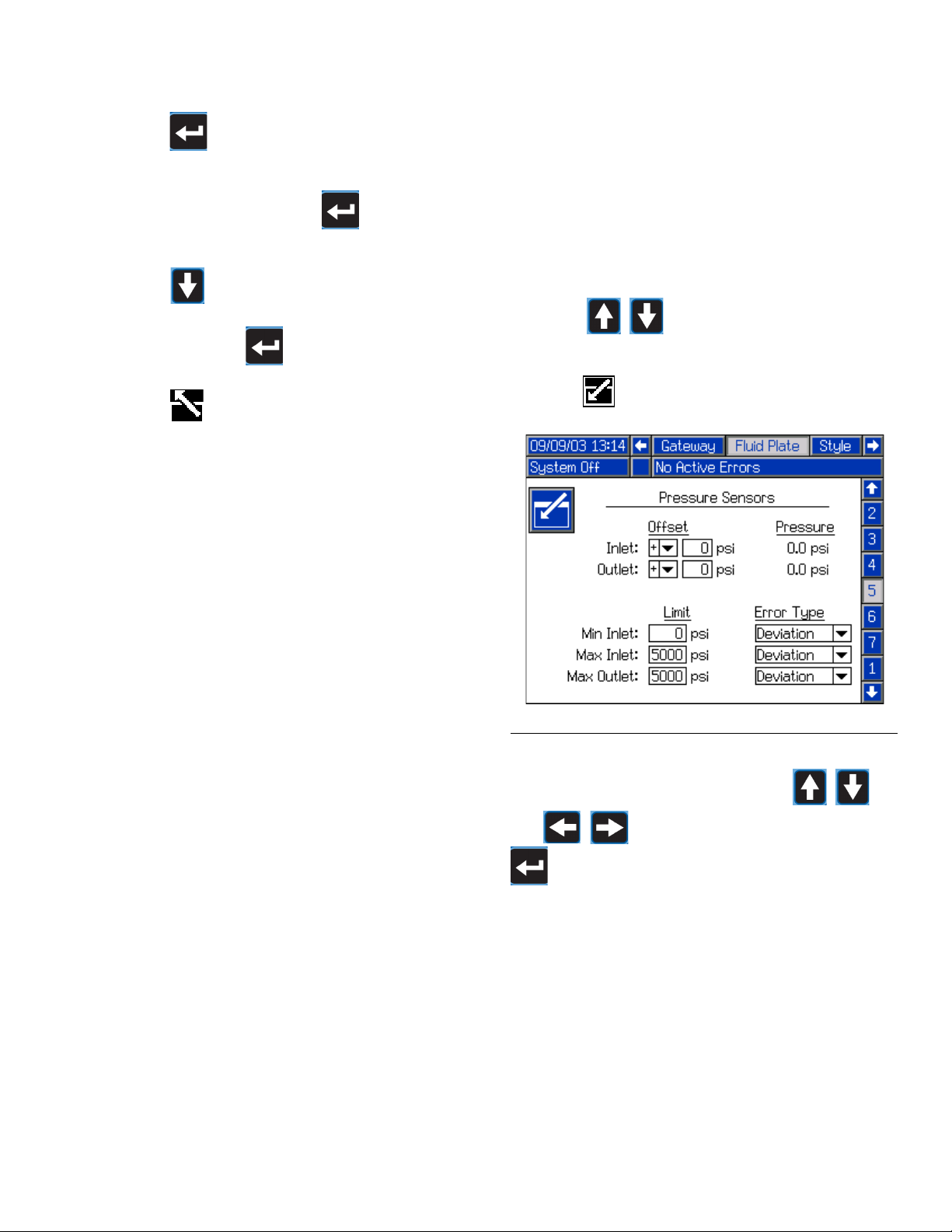
Adjust Pressure Sensors
Set pressure offsets and pressure limits.
NOTE: Inlet sensor settings will be grayed out on
this screen for systems with heated fluid plates.
1. With the system in setup mode, navigate to the Fluid
Plate set of screens.
2. Press to scroll to the Pressure Sensors
screen (screen 5).
3. Press to access the fields to make changes.
The PCF system uses variables (Kp, Ki, and Kd) in the
software calculations to accurately and precisely control
the fluid pressure.
NOTE: It is recommended that these values not be
changed from the factory defaults of 32.00 for Kp,
128.00 for Ki, and 0.00 for Kd. However, if the values
need to be adjusted, see Verify Flow Meter Calibration on page 35.
FIG. 21
NOTE: For the following steps, press
and to navigate through each field, and
to open drop-down menus and enter changes
or selections.
4. Set the desired offset for the inlet and outlet pressures between 0 and 100 psi (0.7 MPa, 7.0 bar).
Remove all pressure on the sensors, and then
adjust the offset so the measured value reads 0.
NOTE: It is recommended that offsets should not be
changed from the factory defaults of 0.
313377L 29
Page 30
System Setup
5. Set the desired minimum and maximum pressure
limits for the inlet, and the desired maximum pressure limit for the outlet.
6. Set the error type (alarm or deviation) that will be
issued:
• If the minimum inlet pressure decreases below
the setting.
• If the maximum inlet pressure increases above
the setting.
• If the maximum outlet pressure increases above
the setting.
7. Press to exit edit mode.
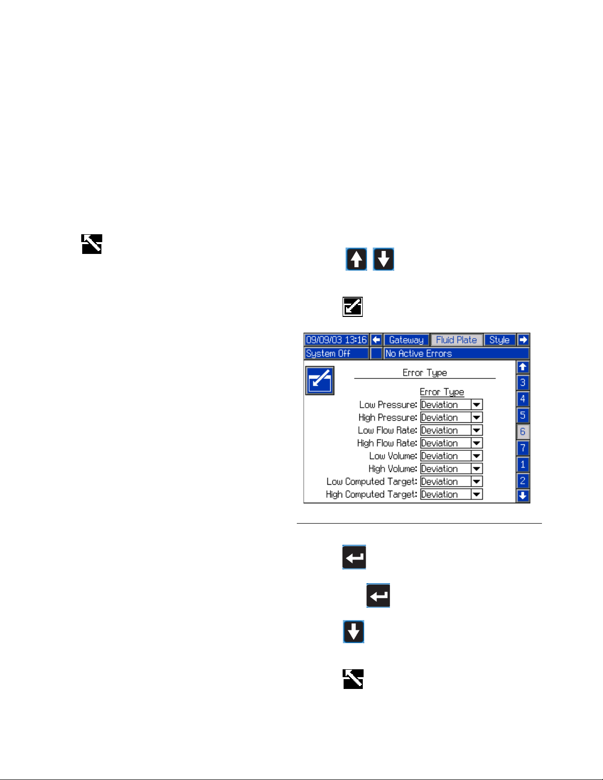
Configure Errors
Set the error type (alarm, deviation, or none) that will be
issued if the pressure, flow rate, volume, or computed
target goes outside the set high and/or low limits. See
Jobs, page 37, for information on the purpose of each
error type.
NOTE: Only the first two error types (low pressure
and high pressure) will be enabled for systems without a flow meter.
1. With the system in setup mode, navigate to the Fluid
Plate set of screens.
2. Press to scroll to the Error Type
screen (screen 6).
3. Press to access the fields to make changes.
FIG. 22
4. Press to open the Low Pressure drop-down
list, and select either Alarm or Deviation for the error
type. Press to enter the selection.
5. Press to move to the next field. Repeat Step 4
for each field.
6. Press to exit edit mode.
30 313377L
Page 31

System Setup
Setup Maintenance Schedule/Parameters
Set the volume (or hours) limit that will trigger a maintenance advisory for the fluid supply, V/P regulator, fluid
regulator, flow meter, and all four guns.
NOTE: Hours is shown instead of Volume for fluid
plates without a flow meter.
The Volume (or Hours) column displays the current
totalizer value. If this value exceeds the set limit, the
value will turn red and a maintenance advisory is issued.
See Maintenance Screen, page 97, for more information about maintenance totalizers.
To set limits:
1. With the system in setup mode, navigate to the Fluid
Plate set of screens.
2. Press to scroll to the Maintenance
Advisory Limits screen (screen 7).
3. Press to access the fields to make changes.
6. Press to exit edit mode.
To reset a totalizer value:
1. Follow Steps 1-3 of To set limits: to make changes
in the Maintenance Advisory Limits screen.
2. Press to scroll to the system compo-
nent to reset.
3. Press to reset the value.
Configure Gateway Settings
Gateway settings differ for each system. See Gateway
Setup Screens, page 88, for guidelines on configuring
each type of Gateway interface.
Setup Styles
The PCF system can store up to 255 styles. See Styles,
page 38, for more information about styles and instructions on setting up styles.
F
IG. 23
4. Enter the desired limit for the air supply and press
to enter the selection.
5. Press to move to the next field. Repeat Step 4
for each field.
Configure Advanced Settings
Use the advanced settings to set or change the format
and display units, such as the language, date format,
and pressure units, for all PCF screens. See Setup
Mode, page 87, for advanced setting guidelines.
313377L 31
Page 32

System Setup
D
C
A
B
Dispense Gun
Signal
Fluid
Regulator
Gun Open
Command
Gun Actually
Open
E
F
On/Off Delays
The PCF fluid regulator can physically respond faster
than the dispense device and its solenoid. As a result,
the fluid regulator can supply material to the dispense
device before the device has time to open. Supplying
material to a closed device can create trapped-pressure.
At the end of a cycle, the dispense device can shut off
before the pressure has dissipated. This can cause a
dispense of an excess of material at the beginning of the
next cycle.
To eliminate these two problems, change the delay time
associated with the opening of the fluid regulator/dispense and/or the closing of the dispense device, see
Table 5: On/Off Delay Variables. For instructions setting on/off delays, see Configure Delay Settings, page
28.
NOTE: On/Off delay can be set for each dispense
device.
In general, delays should be adjusted so the outlet pressure during “no flow” is slightly below the outlet pressure
during dispense.
F
IG. 24 and Table 6: Delay On/Off Timing show delay
ON and OFF timing.
Table 6: Delay On/Off Timing
A Regulator ON
delay
The user sets the fluid regulator ON delay timing.
B Gun ON delay Usually set to zero. Can be
used to change the starting
point of a bead.
C Gun OFF Delay Usually set to zero. Higher
values will lower the trapped
pressure.
D Regulator OFF
delay
The user sets the regulator
OFF delay timing. Zero or
small values will lower the
trapped pressure.
EGun Open
Reaction Time
Time delay for gun to physically open. Delay varies
based on pneumatic hose
length and valve air volume.
F Gun Close
Reaction Time
Time delay for gun to physically close. Delay varies
based on pneumatic hose
length and valve air volume.
Table 5: On/Off Delay Variables
Variable: Sets the Amount of Time:
Gun ON Sets time from Dispense Gun High to
Gun Open command
Regulator
ON
Sets time from Dispense Gun High to
Regulator ON
Gun OFF Sets time from Dispense Gun Low to
Gun Close command
Regulator
OFF
Sets time from Dispense Gun Low to
Regulator OFF
FIG. 24: Timing Delay
32 313377L
Page 33

Operation
Operation
Startup
Initial Startup
1. Ensure the PCF control center is installed and all of
the proper connections to and from the control center have been made. Ensure fittings are tight.
2. Read and understand the Operation (page 33) and
Advanced Display Module (ADM) (page 14) sections of this manual.
3. Continue startup with Step 2 in Standard Startup.
Standard Startup
1. Carefully inspect the entire system for signs of leakage or wear. Replace or repair any worn or leaking
components before operating the system.
2. Press the Stop button (BC). See F
3. Turn on air and electrical power to the system.
4. Turn on the main power to supply power to the PCF.
IG. 7.
Load Material
Before using the system material must be loaded into
the supply system.
1. If this is a new installation, follow the Initial Start up
procedure. Otherwise, follow the Standard Startup
procedure. See page 33.
2. Turn on the fluid supply pressure to the fluid plate
assembly.
3. Place the gun(s) over a waste container.
4. Enter the maintenance screen. See Dispense
From Maintenance Screen, page 36.
5. Select a control mode. See Dispense From Main-
tenance Screen, page 36.
6. If the system status indicator LED (BB) is orange,
press to turn the system on.
5. Check Interface Signals: If this is a new installation, power on each system input and verify that
each input is being received.
6. Turn on the material supply system.
7. Press and hold . Dispense fluid until clean,
air-free fluid flows from the gun.
8. Press again to exit maintenance screen.
313377L 33
Page 34

Operation
Maintenance Mode Operation
Operating from maintenance mode enables the module
to begin dispensing when the user presses . Dis-
pense parameters and duration depend on the selected
control. Dispensing continues for as long as is
pressed.
Verify System Operation
Use maintenance mode to manually check the operation
of the PCF system components before switching over to
automation control (normal operation). See Dispense
From Maintenance Screen, page 36, for instructions
on operating from maintenance mode.
NOTE: Perform any of the following procedures
while in maintenance mode.
Set Inlet Pressure
The inlet pressure reading should be in the range of 300
psi (2.1 MPa, 21 bar) to 500 psi (3.4 MPa, 34 bar) above
the outlet pressure reading under your highest flow condition.
Dispense from Each Gun
Dispense from each gun that will be used in normal
operation to confirm that the entire system is installed
correctly and is capable of delivering desired results.
Follow the steps outlined in Dispense From Mainte-
nance Screen, page 36, to perform each of the following applicable system verification checks.
• For each gun that will be used during normal operation, dispense at each pressure or flow rate that will
be used during normal operation. This verification
check confirms that the system is capable of delivering material at a maximum desired operating point.
• For systems that will operate multiple guns in pressure mode at the same time, dispense from each
gun at the same time. This verification check confirms that the system is capable of delivering material at a maximum desired operating point.
• For each gun operating in bead mode, perform an
initial teaching process. Follow this procedure after
significant system and/or material characteristic
changes.
a. For each flow rate that will be used during nor-
Follow steps in the supply system manual to set the inlet
pressure.
NOTICE
Excessive inlet pressure will cause accelerated wear
on the regulating valve and the pump feed system.
Feed System Pressure Drop
During material flow, the regulator inlet pressure
decreases. The amount the pressure decreases is the
amount of pressure lost between the feed pump and the
regulator inlet.
With high viscosity fluids, long line lengths, or small
diameter line sizes this pressure decrease can be thousands of psi (hundreds of bar). This means that the
static pump pressure is set much higher than the regulator needs at its inlet. To prevent excessive control regulator wear or surging, a mastic fluid pressure regulator is
recommended on the feed line close to the control regulator. The mastic regulator will suppress the static feed
pressure at the control regulator inlet.
mal operation, press until PCF achieves
the flow rate setpoint.
NOTE: During the initial system operation verification, it may take four to five seconds for the system
to learn system characteristics.
b. Continue to press for several seconds
after the desire flow rate is reached to confirm
that the system is capable of maintaining the
desired flow rate.
c. Repeat Steps a and b for a range of flow rates
to confirm that the system responds quickly to
achieve setpoint when is pressed.
34 313377L
Page 35

Operation
fluid mass (g)
density (g/cc)
= measure volume (cc)
K-Factor (new) =
displayed volume (cc) x K-Factor (old)
measured volume (cc)
K-Factor (new) =
displayed volume (cc) x K-Factor (old)
dispensed volume (cc)
Verify Flow Meter Calibration
Most sealant and adhesive materials are compressible.
Since the flow meter measures the material under high
pressure, the actual volume of material dispensed may
vary slightly from the measured volume, due to this
compressibility. If the K-factor is not correct, the displayed volume will not be accurate.
Follow either of the following methods to calibrate the
flow meter during initial setup and on a routine basis to
check for flow meter wear.
Method 1. Using a gram scale
1. Record the flow meter k-factor shown on the Flowmeter Settings screen (Fluid Plate - screen 4). See
F
IG. 20 on page 28.
2. Use a 500 cc or larger beaker. Measure the mass of
the empty beaker.
3. Manually dispense material into the beaker. Hold
the beaker so that the stream of material is submerged in the captured material to minimize air
entrapment in the container.
4. Record the volume dispensed on the Home screen
1. See F
IG. 25 on page 36.
5. Calculate the actual volume dispensed:
6. Calculate the new flow meter K-factor:
7. Enter new K-factor.
8. Repeat the procedure to verify the new K-factor.
Method 2. Without using a gram scale, visual measurement
1. Record the flow meter k-factor shown on the Flowmeter Settings screen (Fluid Plate - screen 4). See
F
IG. 20 on page 28.
2. Use a 500 cc or larger beaker. Measure the mass of
the empty beaker.
3. Manually dispense material into the beaker. Hold
the beaker so that the stream of material is submerged in the captured material to minimize air
entrapment in the container.
4. Record the volume dispensed on the Home screen
1. See F
IG. 25 on page 36.
5. Settle the material into the beaker and view the
actual volume dispensed.
6. Calculate the new flow meter K-factor:
7. Enter new K-factor.
8. Repeat the procedure to verify the new K-factor.
Manually Adjust Control Loop Parameters
NOTE: It is recommended that these values not be
changed from the factory defaults of 32.00 for Kp,
128.00 for Ki, and 0.00 for Kd.
If the system is not maintaining the desired setpoint
while in pressure or bead control mode, manually
change the Kp and Ki values:
NOTE: Pressure parameters should be adjusted first,
even if you typically operate in bead control mode.
1. Begin dispensing material.
NOTE: Begin a new dispense each time control parameters are changed.
2. If the regulator outlet pressure does not closely fol-
low the desired pressure, set Ki to zero then
increase Kp until the proper pressure control is
achieved.
3. If the regulator outlet pressure oscillates rapidly
above and below the commanded pressure,
decrease Kp by 10%. Continue to decrease the Kp
value in 10% increments until the outlet pressure is
stable.
4. Set Ki value to 2 then increase the Ki value until the
system oscillates.
5. Decrease Ki until oscillation stops.
6. Optional: To fine tune the step response in pressure
mode, gradually increase the Kd value.
NOTE: Increasing Kd (pressure only) is typically not
necessary but it may improve step response. However
setting Kd too high may cause the system to oscillate.
7. Stop dispensing.
313377L 35
Page 36

Operation
Dispense From Maintenance Screen
1. Navigate to Home screen 1.
F
IG. 25
2. Press to enter maintenance screen.
4. Press to move to the target fields. Enter the
target pressure, flow rate, and volume (dependent
on control mode) and press to save.
5. Press to move to the gun check boxes. Press
to select the desired guns.
6. Follow Step 2 of Manually Dispense Fluid, page
36.
Manually Dispense Fluid
1. From Home screen 1 press to enter mainte-
nance screen.
2. Press and verify that the gun opens.
F
IG. 26
3. Press to open the Control Mode drop-down
list, and select the preferred control mode. Press
again to exit the drop-down list.
3. Continue to press as long as needed to load
or dispense material.
4. Press again to exit maintenance screen.
36 313377L
Page 37

Operation
Automation Control (Normal) Operation
During automation control (normal operation) the module automatically dispenses when it receives a command from the automation unit.
The automation control operates using the concept of
jobs and styles. For a detailed explanation of jobs and
how they work within the PCF system, see Jobs on
page 37. For a detailed explanation of styles and how
they work within the PCF system, see Styles on page
38.
Jobs
NOTE: See Appendix D - I/O Signal Descriptions,
page 111, for automation input and output signal
descriptions.
A job is a specified amount of material that is dispensed
by the system. The amount of material specified for a
job varies, depending on the application. In some applications, a job may be the amount of material dispensed
on a part. Other applications may define a job to be the
amount of material dispensed on a number of parts or
dispensed over a period of time.
A job is initiated when the automation sends a Style
Strobe signal to the PCF. Once the job is initiated, the
PCF will start tracking the amount of volume requested
by the automation and the amount of material that is
actually dispensed. These volumes will be tracked until
the job is completed. At the end of the job, fault calculations are made and the volumes are stored to non-volatile memory on the PCF system (Job Log).
The PCF system monitors two things to determine when
a job is complete. Either the Dispense Complete signal
is sent by the automation or the job complete timer
expires. The type of job end signal is configured in the
Fluid Plate Control Settings screen to Timer or Gateway. If the timer method is used, the timer begins counting every time the dispense gun is turned off. If the gun
stays off for more than the preset timer value, the job is
considered complete.
Actual (Measured) Volume - The amount of material
measured by the flow meter during a job.
Requested Volume - The amount of material that the
automation tries to dispense during a job. This volume is
calculated by measuring how long the dispense gun is
on, taking in effect the command voltage from the automation over time.
Target Volume - The theoretical amount of material that
a job should have. This value is usually calculated or
found using trial and error when the application is first
set up.
Jobs in Bead Mode
In Bead Mode, all of these volumes are monitored. The
High Volume, Low Volume, and Computed Target faults
are evaluated at the end of the job. The volume alarms
compare the measured volume to the requested volume
and the computed target alarm compares the requested
volume to the target volume.
Jobs in Pressure Mode
In Pressure Mode, the requested volume is not measured. In this mode, the automation command voltage
corresponds to a pressure instead of flow rate. For this
reason the requested volume is not available (as well as
the Computed Target fault). The high and low volume
alarms compare the measured volume to the target volume for pressure mode.
Continuously Running Applications
In some cases the target volume for a job is not known.
An example of a case where the target volume is
unknown is a continuously running system. This would
be a system that does not run jobs, but runs continuously over a day or a shift. In this case, the flow rate
becomes more important than the amount of volume
dispensed in a job. The way to handle this situation is to
set the target volume to a value of zero. This effectively
disables the computed target fault. The controls will still
maintain the desired flow rate and report faults corresponding to the tolerance set for the running style.
Once the job is complete, the job information is stored to
memory. The most recent jobs can be viewed on the
Job screen. The information stored with each job is as
follows. See Job Report Screens, page 97, for instructions on how to view job reports.
313377L 37
Page 38

Operation
Styles
The PCF system has the ability to handle up to 255
styles, depending on the selected option. Styles typically
correspond to different components of a specific system.
NOTE: The number of available styles depends on
the system configuration. See Models on page 4.
Style 0 is specified for purging only.
For each style, an independent target volume and tolerance can be configured. This allows for job-related
faults and logs to be evaluated for each style. The style
is read at the beginning of a job and cannot be changed
until the next job has been initiated.
To setup a style:
1. Press to access the style setup fields.
2. Enter the style number in the Style field.
a. Press while in the Style Name field to
enter the Keyboard screen.
FIG. 28
F
IG. 27
b. Use the arrow buttons on the ADM to scroll
through each letter. Press to enter a letter in the
style name field. See Keyboard Screen, page
94, for further details.
c. Press to accept the new value.
3. Enter the target volume in the Volume field, and the
tolerance percentage in the Tolerance field.
4. Enter precharge mode and parameters. See Pre-
charge Modes on page 39.
5. Press to exit edit mode.
38 313377L
Page 39

Precharge Modes
Operation
NOTE: See the diagram on the following page.
Static Precharge Mode
Display
When Display precharge mode is selected, a static precharge pressure can be defined. When a job is active
and all dispense valves are closed, the regulator will
maintain the defined precharge pressure.
Valve 1
When the “Valve 1” precharge mode is selected, the
outlet pressure will be set according to the current pressure/flow command using Valve 1 scaling values.
Dynamic Precharge Mode
Dynamic precharge control allows the system to better
prepare for the upcoming dispense. The pressure/flow
command is used to actively set the outlet pressure to
the ideal pressure while all dispense valves are closed
and provide a boost while the valve is opening to help
accelerate material.
The “Closed” scaling will be applied when all dispense
valves are closed and the “Opening” scaling will be
applied immediately after a dispense valve starts to
open and continue for the user-specified duration (in
milliseconds). The precharge scaling values modify the
control signals that are necessary to obtain the desired
pressure/flow. The precharge pressure can be changed
dynamically throughout the job by varying the pressure/flow command value.
313377L 39
Page 40

Operation
Dispense Application Direction Dispense Application Direction Dispense Application Direction
Dispense Application Direction Dispense Application Direction Dispense Application Direction
Dispense Application Direction Dispense Application Direction Dispense Application Direction
Dispense Application Direction Dispense Application Direction Dispense Application Direction
-Controls outlet pressure based on desired command while valves are closed.
-Ideal value is typically less than 100% due to the minimal pressure losses within the system when fluid is not
flowing.
-Provides a boost upon valve opening to accelerate material.
-Ideal value is typically greater than 100%.
-The duration for which the valve opening scaling is application before the command is no longer scaled.
-Controls timing of transition from valve “closed” precharge to valve “opening” precharge and regular dispense.
-This delay should approximate the time it takes a dispense to open.
Closed Precharge Scaling Value
Opening Precharge Scaling Value
Opening Precharge Duration Value
Regulator On Delay Value
Value Too Low Ideal Value Value Too High
Value Too Low Ideal Value
Value Too High
Value Too Low Ideal Value Value Too High
Value Too Low Ideal Value Value Too High
40 313377L
Page 41

Operation
Typical Job Cycle
In order for the system to run it must be in the active
state (status light on ADM is green). Before a job begins
the robot outputs should have the following values:
• Style Strobe: 0
• Dispense Complete: 0
• Dispense Gun x On: all should be 0
• Style: Any value is acceptable
A typical job cycle consists of the following dispensing
sequence. See Control Charts, page 43.
1. The robot checks that Dispenser Ready signal is set
to 1. If it is set to 1, a job can begin.
2. The robot sets the Style to the next desired style
value.
3. The robot sets the Style Strobe to 1.
4. PCF reads the Style bits to select the new style. The
system then starts a new job and sets Dispense In
Process to 1.
5. The robot begins dispensing. The robot sets and
clears Dispense Gun x On bits as desired throughout the course of the job.
7. PCF sets the following signals based on the results
of the job. The robot should not read these signals
until after the system clears the Dispense In Process signal.
• Dispenser No Alarm
• Dispenser No Error
• Dispense Volume OK
•Error
• Dispensed Volume
8. PCF clears Dispense In Process to 0 to indicate the
job is complete and all signals from step 7 are valid.
9. The robot must clear Dispense Complete and Style
Strobe (either can be cleared first) before the next
job can start.
Jobs with Command Cable Dispense
Trigger
With the Dispense Trigger Source configured to Command Cable, users only need to trigger the dispense
applicator to start a job. This configuration is useful for
less demanding applications that do not require a full
automation interface.
The following limitations apply when starting a job with
this configuration:
6. When the dispense is complete the robot sets Dispense Complete to 1.
• The style must always be set to Style 1.
• There can be up to a 100 ms delay before dispensing while PCF prepares for the new job
cycle.
• The job end mode timer must be used to end a
job.
313377L 41
Page 42

Operation
Typical Job Cycle Chart
42 313377L
Page 43

Control Charts
Precharge* - Display Mode
Dispense Trigger Source = Command Cable
Precharge* - Valve 1 Mode
* Precharge: After starting a job and prior to opening the dispense valve, the fluid pressure is
increased to try to match the dispensing pressure. This helps the consistency of the dispense.
Shaded areas indicate the precharge is active.
† Only applies to command signals when either “Command Cable” or “gateway” is selected as “Com-
mand Value Source”. In systems containing an automation gateway DGM, when “Digital” is
selected as the “Command Value Type”, the “Digital CMD 1” and “Digital CMD 2” inputs set the
command.
Automation Inputs (PCF Outputs)
Dispense Ready
Dispenser (Fluid Plate) No Alarm
Dispenser (Fluid Plate) No Error
Dispense In Process
Volume OK
Style Bits
Style Strobe
Command Signal Valid†
Regulator Active
Dispense Valve X Open
Automation Outputs (PCF Inputs)
PCF State
Dispense Valve X On
Dispense Complete
* Dispense Gun X Open determined by Enable Guns check boxes on Fluid Plate Control Settings screen.
Operation
313377L 43
Page 44

Operation
Dispense Trigger Source = Gateway
Control Charts (continued)
44 313377L
Page 45

Control Charts (continued)
Dispense Trigger Source = Combined
Operation
313377L 45
Page 46

Pressure Relief Procedure
Dispense Valve Air Solenoid
Pressure Relief Procedure
1. Shut off the fluid supply to the fluid plate assembly.
2. Place a waste container beneath the fluid drain
valve under the filter. Place a waste container
beneath the dispense valve.
3. Slowly open the drain valve at each fluid filter to
relieve fluid pressure. Close valve when pressure
gauge reads zero.
4. In maintenance mode, select Full Open Dispense
Mode, which opens the regulator and dispense
valve. Press the manual dispense button
until the fluid flow stops.
5. If the dispense device cannot be actuated from the
control center, refer to F
lowing steps to open the dispense valve and relieve
fluid pressure:
a. Manually actuate the plunger on the solenoid,
that opens the dispense valve to relieve fluid
pressure. Refer to F
b. Continue actuating the plunger until all pressure
is purged from the system between the needle
and the dispense valve before proceeding to the
next step.
6. Shut off power and air to the fluid supply system.
IG. 29 and perform the fol-
IG. 29.
FIG. 29: Dispense Valve Air Solenoid
If you have followed the previous and still suspect that
a valve, hose, or dispense nozzle is clogged or that
pressure has not been fully relieved, very slowly
remove the dispense tip, clean the orifice, and continue relieving pressure.
If this does not remove the obstruction, very slowly
loosen the hose end coupling and relieve pressure
gradually, then loosen the coupling completely. Clear
the valves or hose. Do not pressurize the system until
the blockage is cleared.
46 313377L
Page 47

Shutdown
BC
TI12362a
1. Press the Stop button (BC).
2. Shut off the material supply to the fluid plate/meter.
3. Follow the Pressure Relief Procedure on page 46.
4. Turn off the PCF system's compressed air supply.
5. Turn off the main power supply.
Shutdown
FIG. 30: ADM - Stop Button
313377L 47
Page 48

USB Data
USB Data
USB Logs
During operation, PCF stores system and performance
related information to memory in the form of log files.
PCF maintains three log files: job logs, error logs, and
dispense data logs. Follow the Download Procedure,
page 49, to retrieve log files.
Job Log
The job log file name is 1-JOB.CSV and is stored in the
DOWNLOAD folder.
The job log maintains a record of the last 1,000 jobs. At
the completion of each job the following data is stored in
the log file:
• Job completion date
• Job completion time
• Job number (sequential number)
• Style number
• Target volume (in units set in the volume units
field)
• Requested volume (in units set in the volume
units field)
• Actual dispensed volume (in units set in the vol-
ume units field)
• Volume units
• Error percentage between actual dispensed vol-
ume and requested volume
• Minimum inlet pressure during job in units of bar
(heated systems will always read 0)
• Average Inlet pressure during job in units of bar
(heated systems will always read 0)
• Maximum inlet pressure during job in units of
bar (heated systems will always read 0)
• Minimum outlet pressure during job in units of
bar
• Average outlet pressure during job in units of
bar
• Maximum outlet pressure during job in units of
bar
• Minimum flow rate during job in units of cc/min
(systems with no flow meter will read 0)
• Average flow rate during job in units of cc/min
(systems with no flow meter will read 0)
• Maximum flow rate during job in units of cc/min
(systems with no flow meter will read 0)
• Elapsed time
Error Log
The error log file name is 2-ERROR.CSV and is stored
in the DOWNLOAD folder.
The error log maintains a record of the last 1,000 errors.
Each error record in the log file contains: the date and
time the error occurred, the error code, and the error
description.
Dispense Data Log
The dispense data log file name is 3-DATA.CSV and is
stored in the DOWNLOAD folder.
The dispense data log maintains a record of system inlet
pressure (heated systems will always read 0), system
outlet pressure, and system flow rate (systems without
flow meters will always read 0). This data is recorded at
one second intervals when a job cycle is in process. The
dispense data log is capable of storing up to two hours
of data.
System Configuration Settings File
The system configuration settings file name is
SETTINGS.TXT and is stored in the DOWNLOAD
folder.
A system configuration settings file automatically downloads each time a USB flash drive is inserted. Use this
file to back up system settings for future recovery or to
easily replicate settings across multiple PCF systems.
Refer to the Upload Procedure, page 50, for instructions on how to use this file.
NOTE: Do not modify the contents of this file.
48 313377L
Page 49

USB Data
Custom Language File
The custom language file name is DISPTEXT.TXT and
is stored in the DOWNLOAD folder.
A custom language file automatically downloads each
time a USB flash drive is inserted. If desired, use this file
to create a user-defined set of custom language strings
to be displayed within the ADM.
The PCF system is able to display the following Unicode
characters. For characters outside of this set, the system will display the Unicode replacement character,
which appears as a white question mark inside of a
black diamond.
• U+0020 - U+007E (Basic Latin)
• U+00A1 - U+00FF (Latin-1 Supplement)
• U+0100 - U+017F (Latin Extended-A)
• U+0386 - U+03CE (Greek)
• U+0400 - U+045F (Cyrillic)
Create Custom Language Strings
The custom language file is a tab-delimited text file that
contains two columns. The first column consists of a list
of strings in the language selected at the time of download. The second column can be used to enter the custom language strings. If a custom language was
previously installed, this column contains the custom
strings. Otherwise the second column is blank.
Modify the second column of the custom language file
as needed and then follow the Upload Procedure,
page 50, to install the file.
The format of the custom language file is critical. The
following rules must be followed in order for the installation process to succeed.
Download Procedure
1. Insert USB flash drive into USB port (BL).
NOTE: System configuration setting files and custom language files can be modified if the files are in
the UPLOAD folder of the USB flash drive. See System Configuration Settings File, Custom Language
File, and Upload Procedure sections.
2. The menu bar and USB indicator lights indicate that
the USB is downloading files. Wait for USB activity
to complete.
3. Remove USB flash drive from USB port (BL).
4. Insert USB flash drive into USB port of computer.
5. The USB flash drive window automatically opens. If
it does not, open USB flash drive from within Win-
®
dows
Explorer.
6. Open Graco folder.
7. Open system folder. If downloading data from more
than one system, there will be more than one folder.
Each folder is labeled with the corresponding serial
number of the ADM (The serial number is on the
back of the ADM.)
8. Open DOWNLOAD folder.
9. Open LOG FILES folder labeled with the highest
number. The highest number indicates the most
recent data download.
10. Open log file. Log files open in Microsoft
default as long as the program is installed. However, they can also be opened in any text editor or
Microsoft
®
Word.
®
Excel® by
• The file name must be DISPTEXT.TXT.
• The file format must be a tab-delimited text file
using Unicode (UTF-16) character representation.
• The file must contain only two columns, with
columns separated by a single tab character.
• Do not add or remove rows to the file.
• Do not change the order of the rows.
• Define a custom string for each row in the second column.
313377L 49
NOTE: All USB logs are saved in Unicode (UTF-16)
format. If opening the log file in Microsoft Word,
select Unicode encoding.
Page 50

USB Data
Upload Procedure
Use this procedure to install a system configuration file
and/or a custom language file.
1. If necessary, follow the Download Procedure,
page 49, to automatically generate the proper folder
structure on the USB flash drive.
2. Insert USB flash drive into USB port of computer.
3. The USB flash drive window automatically opens. If
it does not, open USB flash drive from within Windows Explorer.
4. Open Graco folder.
5. Open system folder. If working with more than one
system, there will be more than one folder within the
Graco folder. Each folder is labeled with the corresponding serial number of the ADM. (The serial
number is on the back of the module.)
6. If installing the system configuration settings file,
place SETTINGS.TXT file into UPLOAD folder.
7. If installing the custom language file, place
DISPTEXT.TXT file into UPLOAD folder.
8. Remove USB flash drive from computer.
9. Install USB flash drive into PCF system USB port.
10. The menu bar and USB indicator lights indicate that
the USB is downloading files. Wait for USB activity
to complete.
11. Remove USB flash drive from USB port.
NOTE: If the custom language file was installed,
users can now select the new language from the
Language drop-down menu in the Advanced Setup
Screen 1.
50 313377L
Page 51

Troubleshooting
Troubleshooting
NOTE: Check all possible solutions in the chart
below before you disassemble the system.
Troubleshooting for individual regulators and flow
meters is discussed in their separate manuals; refer to
Related Manuals on page 3. Also refer to Error Codes
and Troubleshooting, page 55, for detailed information
on how error codes are communicated.
Fluid Modules
Problem Cause Solution
No outlet pressure Air pressure low Verify air pressure is above 60 psi
(0.4 MPa, 4 bar)
No “Gun On” signal from automation
unit
No air signal to air diaphragm Check for loose/disconnected con-
False signal being sent to control Check outlet pressure sensor output;
High outlet pressure Needle/seat is worn Rebuild regulator; replace needle/
Air leaks from fluid module Loose air connections Check air connections; tighten if nec-
Worn gaskets Check/replace gaskets on V/P and
Check output and wiring from automation unit
nector to V/P valve; tighten
verify that it corresponds to zero
pressure; replace sensor and/or
amplifier
seat
essary
solenoid valve
313377L 51
Page 52

Troubleshooting
Fluid Meter
Problem Cause Solution
No flow measurement Flow meter pick-up sensor loose Tighten flow meter pick-up sensor
Flow too low Verify flow rate is above minimum
for the flow meter selected
Loose wiring Verify connection from flow meter to
FCM
Damaged flow meter pick-up sensor Replace pick-up sensor
False measurement Flow meter not calibrated Calibrate flow meter
System not grounded properly Verify system ground
Noisy power source Verify clean power supply power to
main enclosure
Flow reported is not correct or
inconsistent
Flow meter not calibrated Calibrate flow meter
Flow meter is worn Replace flow meter
Fluid Regulator
Problem Cause Solution
No pressure regulation Damaged diaphragm Replace diaphragm
Leaking or dirty seat Replace cartridge, or clean seat
No fluid flow Damaged valve actuator Replace valve actuator
Pressure creeps above setting Metal chip or contamination
between ball and seat
Damaged diaphragm Replace diaphragm
Damaged o-ring or improper seal Replace the o-ring under the seat
Damaged or clogged air regulator or
line
Leaking or dirty seat Replace cartridge, or clean seat
Large change in inlet pressure Stabilize regulator inlet pressure
Pressure drops below setting Empty/clogged supply line Fill/flush supply line
Damaged or clogged air regulator or
line
Using valve beyond its rated flow
capacity
Large change in inlet pressure Stabilize regulator inlet pressure
Fluid leaks from spring housing Loose fluid housing Tighten the four cap screws
Damaged diaphragm Replace diaphragm
Chatter
Excessive pressure differential be
tween pump and gun
Excessive flow rate
Replace cartridge, or clean seat
area
Clear obstruction in line. Service
regulator if necessary
Clear obstruction in line. Service
regulator if necessary
Install valve for each spray gun or
dispensing valve
Reduce pump pressure to not more
than 2000 psi (14 MPa, 138 bar)
greater than required gun pressure.
Reduce fluid flow through regulator.
Connect only one spray gun or dispensing valve to each fluid regulator
52 313377L
Page 53

Troubleshooting
Dispense Valves
Problem Cause Solution
Valve not opening Air not getting to open port Verify air pressure solenoid
No “Gun On” signal from automation unit
Valve not shutting off Air not getting to close port (except
AutoPlus valve)
“Gun On” signal from automation
unit is on
Sluggish open/close Air pressure low Verify air pressure is above 60 psi
Needle/seat worn Rebuild valve; replace needle/seat
Pressurized material past the valve
shut-off is escaping
Material leaks from back of valve Shaft seal is worn Rebuild valve; replace seals
Air leaks from dispense valve Loose air connections Check air connections; tighten if
Worn piston o-ring Rebuild valve; replace piston o-ring
Check input from automation unit
Verify air pressure to solenoid
Verify solenoid operation
Verify air line routing and connections
Check input from automation unit
(0.4 MPa, 4 bar)
Reduce running pressure
Reduce nozzle length
Increase nozzle orifice size
necessary
313377L 53
Page 54

Troubleshooting
Gateway Module
Problem Cause Solution
No communication Incorrect wiring Check wiring per fieldbus standard.
Refer to PCF Gateway status indicators and Appendix C - Commu-
nications Gateway Module (CGM)
Connection Details, page 105.
Incorrect fieldbus settings Confirm fieldbus settings at automa-
tion controller (fieldbus master) and
PCF Gateway (fieldbus slave).
Refer to Appendix A - Advanced
Display Module (ADM), page 85,
for information on PCF Gateway
configuration settings.
Incorrect data
Incorrect fieldbus configuration file
installed on automation controller
(fieldbus master)
Incorrect map installed on PCF
Gateway
Download PCF fieldbus configuration file from www.graco.com, and
install on automation controller
(fieldbus master).
Confirm correct PCF data map is
installed on PCF Gateway. Refer to
Appendix A - Advanced Display
Module (ADM), page 85, for infor-
mation on how to determine
installed data map. If necessary,
install a new Gateway data map.
Refer to Upgrade Gateway Mod-
ule Fieldbus Map, page 64, for
instructions, and to Control Center
Assembly Parts, page 78, for map
token part number.
LED Diagnostic Information
The following LED signals, diagnosis, and solutions are the same for the display module, fluid control module, an
Gateway module.
Module Status LED Signal Diagnosis Solution
Green on System is powered up -
Yellow Internal communication in progress -
Red solid Hardware failure Replace display module, fluid control
module, or Gateway module
Red flashing fast Uploading software -
Red flashing slow Token error Remove token and upload software
token again.
54 313377L
Page 55

Errors
Error
Code
Errors
View Errors
When errors occur the highest priority active error is displayed in the menu bar. The previous 140 errors are displayed on the error report screens. See Run Mode,
page 95, for instructions on navigating to and through
the error report screens.
There are three levels of errors: alarms, deviations, and
advisories. Alarms are critical and require immediate
correction; therefore, the system automatically shuts
down. Deviations are critical and require attention but
not immediately. Advisories are not critical but still
require attention.
NOTE:
• Alarms set the dispenser ready signal LOW.
• Advisories and deviations do not set the dispenser
ready signal LOW.
Diagnose Errors
See Error Codes and Troubleshooting for valid error
codes, possible causes, and solutions.
Clear Errors and Reset Control Unit
Press to clear an error before restarting the control
unit.
Error Codes and Troubleshooting
NOTE: Error codes are stored in the error log, and displayed on the error report screens. Gateway error numbers are reported over the Gateway interface.
Error
Code
0000 0 No Active Errors No errors n/a n/a No action necessary
EP0X 1 Power Up Control box power up Record only n/a No action necessary
EC0X 2 Setup Values
Gateway
Error No. Error Name
Changed
Error
Description Error Type Cause Solution
System Errors
Setup change notification
Record only A setup value was
changed on the display
No action necessary if
changes were desired
313377L 55
Page 56

Errors
Error
Code
EAU0 3 Download to
EBU0 4 Download to
WSU0 5 USB configura-
WNC0 10 ADM Key Token
WMC0 19 Display Error
CAC0 20 CGM Communi-
WMG0 21 Gateway Map
CBG0 22 Gateway Reset Gateway reset Advisory
WMG0 29 Gateway Error
B7C0 30 Style Out of
B40X
B30X
Gateway
Error No. Error Name
USB in Process
USB Complete
tion error
Error
Detected
cation Error
Error
Detected
Range
31 High Volume or
High Mass
Error
Description Error Type Cause Solution
Control Center Errors
Information is currently
being downloaded to
USB
Download to the USB is
complete
USB configuration error Advisory USB configuration
Missing or invalid key
token
ADM error detected;
includes any error not
covered by another
more specific error
Communication lost
between CGM and
ADM
Missing or invalid map Advisory Missing or invalid
Gateway error
detected; includes any
error not covered by
another more specific
error
Style is out of range Alarm Style requested by
Material dispensed
during last dispense
cycle was above
amount requested plus
the allowed tolerance
Advisory
(self-clearing)
Advisory
(self-clearing)
Alarm An ADM key token is
Alarm
Advisory ADM and CGM are no
(self-clearing)
Alarm
Alarm or
Deviation
(user selectable)
n/a No action necessary
n/a No action necessary
Reinstall system soft-
invalid or not present
required to run the
system
longer communicating
CGM is not functioning Replace the CGM if the
Gateway map
Gateway setting(s)
changed
automation controller
exceeds number of
styles in system
PCF regulator is not
regulating correctly
Incorrect style target
volume or tolerance
ware on display
Verify the key token is
installed
Verify the key token
part number is correct
for the PCF ADM
Reconnect or replace
CAN cable
red status LED is solid
Install PCF map in
Gateway
Wait for reset to complete before attempting automation control
Use a style number
that is in range
Increase number of
styles in PCF; purchase accessory key
token
Check regulator and
repair if necessary
Enter correct values or
set tolerance to 0% to
disable fault
56 313377L
Page 57

Errors
Error
Code
B10X
B20X
B1CX
B2CX
B3CX
B4CX
CAD1 50 Fluid Plate Com-
WND1 51 Fluid Plate Key
Gateway
Error No. Error Name
32 Low Volume or
Low Mass
33 Low Computed
Target
34 High Computed
Target
munication Error
Token Error
Error
Description Error Type Cause Solution
Control Center Errors (continued)
Material dispensed
during last dispense
cycle below amount
requested minus the
allowed tolerance
Requested volume differs from entered process target by more
than entered tolerance
for style requested
Requested volume differs from entered process target by more
than entered tolerance
for style requested
Fluid Plate Errors
Communication lost
between fluid plate and
ADM
Missing or invalid key
token
Alarm or
Deviation
(user selectable)
Alarm or
Deviation
(user selectable)
Alarm or
Deviation
(user selectable)
Alarm FCM is not
Alarm FCM key token is
Partially plugged tip or
supply system
Insufficient flow to
PCF regulator inlet
PCF regulator is not
regulating correctly
Check regulator;
repair if necessary
Entered process target
incorrectly
Entered tolerance
incorrectly
Requested volume
incorrectly
Automation problem Verify automation is
Entered process target
incorrectly
Entered tolerance
incorrectly
Requested volume
incorrectly
Automation problem Verify automation is
communicating
FCM is not functioning Replace FCM if red
required to run system
Clean tip and/or supply
system
Increase flow rate to
regulator inlet
Incorrect style target
volume or tolerance
setting
Enter correct process
target
Enter correct tolerance
Check automation program
correct
Enter correct process
target
Enter correct tolerance
Check automation program
correct
Reconnect or replace
CAN cable
status LED is solid
Verify FCM key token
is installed
Verify FCM key token
is correct part number
P6D1 52 Outlet Pressure
Transducer Error
P6F1 53 Inlet Pressure
Transducer Error
313377L 57
Outlet pressure transducer error
Inlet pressure transducer error
Alarm Problem detected with
outlet pressure transducer
Advisory Problem detected with
inlet pressure transducer
Verify outlet pressure
transducer is installed
and/or connected correctly
Replace if necessary
Verify inlet pressure
transducer is installed
and/or connected correctly
Replace if necessary
Page 58

Errors
Error
Code
F6D1 54 Flow Meter Error Flow Meter error Alarm Problem detected with
WED1 55 V/P Error V/P error Alarm Problem detected with
WJD1 56 Dispense Valve 1
WJD2 57 Dispense Valve 2
WJD3 58 Dispense Valve 3
Gateway
Error No. Error Name
Error
Error
Error
Error
Description Error Type Cause Solution
Fluid Plate Errors (continued)
flow meter
V/P
Dispense valve 1 error Alarm Problem detected with
dispense valve 1
Dispense valve 2 error Alarm Problem detected with
dispense valve 2
Dispense valve 3 error Alarm Problem detected with
dispense valve 3
Verify flow meter is
installed and/or connected correctly
Replace if necessary
Verify outlet pressure
transducer is installed
and/or connected correctly
Replace if necessary
Verify dispense valve 1
is installed and/or connected correctly
Replace if necessary
Verify dispense valve 2
is installed and/or connected correctly
Replace if necessary
Verify dispense valve 3
is installed and/or connected correctly
WJD4 59 Dispense Valve 4
Error
WSD1 60 Incompatible
Gun Settings
F7D1 61 Closed Gun Flow System reading flow
V2D1 62 Low Analog Analog command
Dispense valve 4 error Alarm Problem detected with
Incompatible settings
for multiple gun operation; attempted to dispense
meter pulses with
gun(s) closed
dropped below minimum value (user
defined) while dispensing
Replace if necessary
Verify dispense valve 4
dispense valve 4
Alarm Attempted to dis-
pense from multiple
guns with incompatible
settings
Alarm Dispense hose leak Check hose; replace if
Flow meter providing
false pulses
Dispense valve not
operating correctly
Deviation Bad or loose com-
mand cable connection
Entered command
mode incorrectly
Automation program
error
is installed and/or connected correctly
Replace if necessary
Check gun mode settings (on fluid plate
setup screen)
Verify automation programming
needed
Replace flow meter
sensor or calibrate
meter
Repair dispense valve
Check command cable
and connection
Enter correct command code
Verify correct automation program
58 313377L
Page 59

Errors
Error
Code
WFD1 63 Flow Meter
EJD1 64 Job Cycle Time
WXD1 65 Fluid Plate Error
P3F1
P4F1
P3D1
P4D1
P1F1
P2F1
P1D1
P2D1
Gateway
Error No. Error Name
Required
Out
Detected
66 Maximum Inlet
Pressure
67 Maximum Outlet
Pressure
68 Minimum Inlet
Pressure
69 Low Pressure Measured outlet pres-
Error
Description Error Type Cause Solution
Fluid Plate Errors (continued)
Operating mode
requires flow meter.
Advisory is issued if
fluid plate settings
require a flow meter but
meter is not present.
Alarm is issued if dispense is attempted in
mode that requires a
flow meter but meter is
not present.
Job cycle time out Alarm Automation signals did
Fluid plate error
detected; includes any
error not covered by
another more specific
error
Inlet pressure to regulator is above upper limit
set for operation
Outlet pressure of regulator is above upper
limit set for operation
Inlet pressure to regulator is below lower limit
set for operation
sure less than desired
outlet pressure minus
tolerance
Alarm or
Advisory
(self-clearing)
Alarm
Alarm or
Deviation
(user selectable)
Alarm or
Deviation
(user selectable)
Alarm or
Deviation
(user selectable)
Alarm or
Deviation
(user selectable)
Selected gun mode
settings require flow
meter
FCM key token missing or invalid
not properly end job
cycle
Incorrect set limit Verify limit is set cor-
Material supply pressure is too high
Failed transducer Check transducer;
Incorrect set limit Verify limit is set cor-
Material supply pressure is too high
Failed transducer Check transducer;
Incorrect set limit Verify limit is set cor-
Material supply pressure is too low
Failed transducer Check transducer;
Incorrect limit set Verify limit is set cor-
No or insufficient
material flow
Dispense valve needle
is stuck closed
Dispense valve leaking
Regulator not operating correctly
Pump wink passed
through outlet
Failed transducer Check transducer;
Check gun mode settings
Purchase meter
enabled token for FCM
and install flow meter
Check for FCM key
token error
Check automation programming per job
operating instruction
rectly
Decrease material supply pressure
replace if necessary
rectly
Decrease material supply pressure
replace if necessary
rectly
Increase crease material supply pressure
replace if necessary
rectly
Increase material flow
rate
Dislodge and inspect
needle
Repair dispense valve
Repair regulator
Increase pump pressure
replace if failed
313377L 59
Page 60

Errors
Error
Code
P3D1
P4D1
F1D1
F2D1
F3D1
F4D1
Gateway
Error No. Error Name
70 High Pressure Measured outlet pres-
sure greater than
desired outlet pressure
plus tolerance
71 Low Flow Rate Measured flow rate less
than desired flow rate
minus tolerance
72 High Flow Rate Measured flow rate
greater than desired
flow rate plus tolerance
Error
Description Error Type Cause Solution
Fluid Plate Errors (continued)
Alarm or
Deviation
(user selectable)
Alarm or
Deviation
(user selectable)
Alarm or
Deviation
(user selectable)
Incorrect limit set Verify limit is set cor-
rectly
Dispense hose/device
plugged
Failed transducer Check transducer;
Regulator is not closing completely when it
should
Fluid supply too low to
achieve desired flow
rate
Tip plugged Clean/replace tip
No air pressure to
solenoid valves
No flow meter signal Check cable and sen-
No material supply Replace drum or turn
Incorrect flow tolerance of flow fault time
Operating below minimum regulator operating pressure
Regulator worn or not
operating correctly
Flow meter providing
false pulses
Incorrect flow fault tolerance or flow fault
time
Clean/replace
hose/device
replace if failed
Repair regulator
Increase fluid supply
pressure or check for
clogged filter
Turn on air to solenoid
valves
sor
on pumps
Enter correct tolerance or flow fault time
Increase fluid pressure above regulator
minimum
Repair regulator
Replace flow meter
sensor
Enter correct tolerance or flow fault time
60 313377L
Page 61

Errors
Error
Code
EKD1 73 Shot Terminated
EHD1 74 Purge Timer
EAC1 75 Maintenance
EBC1 76 Maintenance
MHD1 77 Maintenance
MFD1 78 Maintenance
MED1 79 Maintenance
MCD1 80 Maintenance
MDD1 81 Maintenance
MDD2 82 Maintenance
MDD3 83 Maintenance
MDD4 84 Maintenance
Gateway
Error No. Error Name
by Job Timer
Expired
Mode Entered
Mode Exited
Due - Regulator
Due - Flow Meter
Due - V/P
Due - Supply
Due - Gun 1
Due - Gun 2
Due - Gun 3
Due - Gun 4
Error
Description Error Type Cause Solution
Fluid Plate Errors (continued)
Shot dispense cycle
terminated by job timer
Purge timer expired Advisory PCF purge timer (style
Maintenance mode
entered
Maintenance mode
exited
Maintenance due for
regulator
Maintenance due for
flow meter
Maintenance due for
V/P regulator
Maintenance due for
supply system
Maintenance due for
gun 1
Maintenance due for
gun 2
Maintenance due for
gun 3
Maintenance due for
gun 4
Advisory Job end timer was
used to stop shot dispense
0) has expired
Advisory
(self-clearing)
Advisory
(self-clearing)
Advisory Totalizer exceeded
Advisory Totalizer exceeded
Advisory Totalizer exceeded
Advisory Totalizer exceeded
Advisory Totalizer exceeded
Advisory Totalizer exceeded
Advisory Totalizer exceeded
Advisory Totalizer exceeded
Entered maintenance
dispense mode
Exited maintenance
dispense mode
limit setting
limit setting
limit setting
limit setting
limit setting
limit setting
limit setting
limit setting
No action required if
timed shot is desired
Automation control
requests purge
No action required
No action required
Service component
If necessary, reset
totalizer
Service component
If necessary, reset
totalizer
Service component
If necessary, reset
totalizer
Service component
If necessary, reset
totalizer
Service component
If necessary, reset
totalizer
Service component
If necessary, reset
totalizer
Service component
If necessary, reset
totalizer
Service component
If necessary, reset
totalizer
313377L 61
Page 62

Maintenance
Maintenance
Prior to performing any maintenance procedures, follow
the Pressure Relief Procedure on page 46.
Maintenance Schedule
The following tables list the recommended maintenance procedures and frequencies to operate the equipment
safely. The maintenance is divided between mechanical and electrical tasks. Maintenance must be performed by
trained personnel per this schedule to assure safety and reliability of the equipment.
Mechanical
Operator Maintenance Person
Task Daily Weekly Monthly
Inspect system for leaks
Depressurize fluid, after opera-
tion
Remove heat from system,
after operation
Inspect filter (234967) bowls
and drain
Check hoses for wear
Check/tighten fluid connections
Check/tighten air connections
Lubricate dispense valves*
Rebuild regulator*
Rebuild dispense valve*
Replace air filter
Replace Solenoid
Replace V/P valve
* Check component manual for more detailed maintenance information.
3-6
months
or
125,000
cycles
18-24
months
or
500,000
cycles
36-48
months
or
1,000,000
cycles
7000
hours
Electrical
Task Weekly
Check cables for wear
Verify cable connections
Verify operation of “System Stop” button
* Check Component Manual for more detailed maintenance information.
62 313377L
Page 63

Maintenance
r_24E451_3B9900_3a
Access Panel
Token
BL
r_24E451_3B9900_4a
TI12319A
Access
Cover
TI12320A
CK
Token
Advanced Display Module (ADM)
Upgrade Software
NOTE: Back up the custom language file (if
installed) before upgrading software. See USB Data,
page 48, for more information.
1. Turn off power to the system.
2. Remove token access panel, and then remove the
key token (do not discard token).
Cleaning
Use any alcohol-based household cleaner, such as
glass cleaner, to clean the display.
Upgrade Gateway Module Software
NOTE: The Gateway module connection to the system is temporarily disabled during the installation of
upgrade tokens. The following instructions apply to
all Gateway module connectors.
1. Turn off power to the system.
2. Remove the access cover.
F
IG. 31: Remove Access Panel
3. Insert and press token firmly into slot.
NOTE: There is no preferred orientation of token.
F
IG. 32: Insert Token
4. Turn on power to the system. The red indicator light
(BL) will flash until new software is completely
loaded.
5. After the red indicator light shuts off, turn off power
to the system.
6. Remove token.
FIG. 33: Remove Access Cover
3. Insert and press token firmly into slot.
NOTE: There is no preferred orientation of token.
4. Turn on power to the system. The red indicator light
(CK) will flash until new software is completely
loaded.
7. Reinstall key token, and replace token access
panel.
313377L 63
IG. 34: Insert Token
F
Page 64

Maintenance
Access
Cover
TI12319A
Token
TI12320A
Push Button
CK
5. After the red indicator light shuts off, turn off power
to the system.
6. Remove token.
7. Replace access cover.
Upgrade Gateway Module Fieldbus Map
NOTE: The fieldbus connection is temporarily disabled during the upgrade of a map token. The following instructions apply to all Gateway module
connectors.
1. Remove the access cover.
3. Press and hold the push button for three seconds
and then release. The red indicator light (CK) will
flash twice, pause, and then once after the data
map is uploaded.
FIG. 36: Insert Token
4. Remove map token (CC) when software has successfully uploaded.
F
IG. 35: Remove Access Cover
2. Insert and press map token firmly into slot.
NOTE: There is no preferred orientation of token.
5. Replace access cover.
64 313377L
Page 65

Maintenance
TI12334A
Access
Cover
CK
Token
TI12335A
Upgrade Fluid Control Module (FCM) Software
NOTE: The FCM connection is temporarily disabled
during the installation of the upgrade a key token.
1. Turn off power to the system.
2. Remove access cover.
F
IG. 37: Remove Access Cover
Air Filter Maintenance
To prevent filter element damage, replace air filter every
two years or when pressure drop becomes 0.1 MPa (1.0
bar, 14.5 psi); which ever occurs first.
Replacement Air Filters
Part Description
123091 5 micron air filter
123092 0.3 micron air filter
3. Insert and press token firmly into slot.
NOTE: There is no preferred orientation of token.
4. Turn on power to the system. The red indicator light
(CK) will flash until new software is completely
loaded.
IG. 38: Insert Token
F
5. After the red indicator light shuts off, turn off power
to the system.
6. Remove token.
7. Replace access cover.
313377L 65
Page 66

Repair
129
108
101
124
125, 126, 127
109
131
103
r_pf0000_313377_18a
Repair
Fluid Plate Assembly
This section describes how to remove and replace components on the fluid plate assembly.
Prepare Fluid Plate Assembly for
Repair
1. Disconnect the CAN cable from the fluid plate.
2. Perform Pressure Relief Procedure on page 46.
3. Remove the fluid plate assembly shroud. See Fluid
Plate Assembly Parts, page 80.
Repair Flow Meter
For complete flow meter (129) repair instructions refer to
the maintenance and repair section of manual 309834.
Remove Flow Meter from Mounting Plate
1. Prepare Fluid Plate Assembly for Repair, page
66.
2. Disconnect the flow meter cable (131) from the flow
meter sensor. See F
3. Disconnect the material hose.
4. Disconnect the swivel fitting (109) from the regulator.
5. Loosen the four screws (127) and washers (125,
126); remove the bracket (124) and flow meter
(129).
6. The flow meter weighs approximately 15 lbs. (6.75
kg). Carefully lift it off the mounting plate (101).
IG. 39.
FIG. 39: Fluid Plate Assembly
66 313377L
Page 67

Repair
r_pf0000_313377_34a
129
108
125
124
126
127
109
137
118
132
r_pf0000_313377_33a
122
121
118
r_pf0000_313377_31a
Install Flow Meter on Mounting Plate
1. Rest the flow meter (129) and bracket (124) on the
fluid plate while threading the swivel fitting (109)
onto the regulator material inlet. See F
2. Tighten the swivel fitting to the regulator material
inlet.
3. Tighten the four screws (127) and washers (125,
126) to hold the bracket and flow meter in place.
IG. 39.
4. Remove the dispense valve solenoid (132) and
replace it with a new solenoid.
FIG. 41
5. Secure the new solenoid to the bracket with screws.
6. Reconnect the FCM cable and all three air tubes.
F
IG. 40
4. Check that the flow meter and regulator (108) are
still aligned.
5. Connect the material hose.
6. Connect the flow meter cable (131).
Replace Solenoid
1. Prepare Fluid Plate Assembly for Repair, page
66.
2. Disconnect FCM cable and all three air tubes.
3. Remove both screws (137) from valve bracket
(118).
Replace V/P Valve
1. Prepare Fluid Plate Assembly for Repair, page
66.
2. Disconnect the FCM cable and both air tubes.
3. Remove both valve screws (122) from valve bracket
(118).
4. Remove the V/P valve (121) and replace it with a
new V/P valve.
F
IG. 42
313377L 67
Page 68

Repair
128
121
118
132
r_pf0000_313377_30a
102
103
106
105
103
102
5. Secure the new V/P valve to the bracket with
screws.
6. Reconnect the FCM cable and both air tubes.
Replace Fluid Control Module
1. Prepare Fluid Plate Assembly for Repair, page
66.
2. Remove the four screws (128) from the valve
bracket (118), and remove the bracket. (Leave the
dispense valve solenoid (132) and V/P valve (121)
attached to the valve bracket.)
Replace Fluid Control Module Base
1. Prepare Fluid Plate Assembly for Repair, page
66.
2. Remove the FCM (103); follow Replace Fluid Con-
trol Module. (Leave the cables attached to the
FCM.)
3. Remove the power supply cable from the base
(102).
4. Remove the four screws (105) and ground screw
(106) from the base and replace it with a new base.
F
IG. 43
3. Remove the following cables from FCM:
• dispense valve solenoid cable
• meter sensor cable
• both V/P cables
• I/O cable
• inlet pressure transducer cable (ambient models only)
• outlet pressure transducer cable
4. Remove the two screws from FCM (103) and
replace with a new FCM.
5. Secure the new FCM to the base (102) with screws.
6. Reconnect the cables listed in Step 3.
7. Reattach the valve bracket using screws.
FIG. 44
5. Secure the base to the fluid plate (101) with screws.
6. Reconnect the power supply cable.
7. Reattach the FCM; follow Replace Fluid Control
Module.
68 313377L
Page 69

Replace Transducer O-Rings
117
108
r_pf0000_313377_16a
120
CH
CG
1. Prepare Fluid Plate Assembly for Repair, page
66.
2. Remove the fluid outlet pressure sensor (117) from
the regulator (108).
Repair
F
IG. 45
3. Press the transducer (CG) out of the retainer nut
(CH).
4. Remove the faulty o-ring (120) and replace with
new.
F
IG. 46
5. Press the transducer back into the retainer nut.
6. Reconnect the fluid outlet pressure sensor to the
regulator.
313377L 69
Page 70

Repair
diaphragm
and valve
actuator
subassembly
cartridge
assembly
Torque Sequence for Regulator
Base Housing Screws (CF)
4
2
3
1
CD
CE
CC
Cartridge Regulator 244734 Shown
CF
Repair Fluid Regulator
For complete cartridge fluid regulator repair refer to
instruction manual 308647. For complete mastic fluid
regulator repair refer to instruction manual 307517.
See F
IG. 47 and perform the following steps.
NOTICE
Carefully handle the hard carbide parts ball, valve
actuator, and valve seat to avoid damaging them.
1. Prepare Fluid Plate Assembly for Repair, page
66.
2. Remove the cartridge assembly by loosening the
valve housing (CE) with a 6 mm hex wrench and
pulling the cartridge assembly out of the base housing (CD).
NOTE: The retaining nut (CC) often loosens when
removing the cartridge assembly from the base
housing. Be sure to re-torque as described in step 4.
3. Inspect and clean the internal walls of the base
housing (CD).
NOTE: Be careful to not scrape or gouge the internal
walls of the base housing. They are a sealing surface.
4. Re-torque the retaining nut (CC) to 140-160 in-lb
(16-18 N•m).
NOTE: You must re-torque the retaining nut before
you install it in the base housing during step 5.
5. Install the new cartridge assembly in the base housing (CD), and torque the valve housing (CE) to
30-35 ft-lb (41-48 N•m).
NOTE: The valve seat is double sided and may be
reversed for extended life. The o-ring and ball must
be replaced. See instruction manual 308647.
FIG. 47: Replace Cartridge Assembly
70 313377L
Page 71

Repair
117
116
Screw
Power Output Cable
Replace Amplifier
(Heated fluid plates only)
1. Prepare Fluid Plate Assembly for Repair, page
66.
2. Disconnect pressure sensor cable (117) and power
output cable.
3. Loosen four screws on amplifier (116) cover, and
then remove cover.
4. Remove four screws (105) securing amplifier to
bracket.
5. Remove amplifier and replace with a new amplifier.
6. Secure new amplifier to bracket with four screws.
7. Replace amplifier cover and tighten screws.
8. Reconnect pressure sensor cable (117) and power
output cable.
F
IG. 48: Replace Amplifier
313377L 71
Page 72

Repair
Calibrate Amplifier
(Heated fluid plates only)
1. Prepare Fluid Plate Assembly for Repair, page
66.
2. Remove outlet pressure sensor from outlet fitting to
ensure there is no pressure applied to the sensor.
Adjust Display Settings
3. With the system in setup mode, navigate to the
Advanced set of screens.
4. Press to scroll to Advanced Setup
Screen 2.
9. Press to scroll to the Pressure Sensors
screen (screen 5).
10. Press to access the fields to make changes.
11. Press to move the Outlet Offset field. Set the
5. Press to access the fields to make changes.
6. Press to move the Pressure Units field. Press
to open the drop-down list, and select psi.
Press to enter the new units.
7. Press to exit edit mode.
8. With the system still in setup mode, navigate to the
Fluid Plate set of screens.
psi to 0. Press to enter the new setting.
12. Press to exit edit mode.
Adjust Amplifier Settings
13. Remove cover from amplifier (116). See Replace
Amplifier, page 71.
14. Ensure the EXCITATION SELECTOR jumper is in
the middle position (5 Vdc).
15. Ensure the COARSE GAIN dipswitch 1 is set to ON.
All others should be set to OFF.
16. Adjust the FINE ZERO potentiometer until the outlet
pressure on the display reads 0.
NOTE: The display is not capable of displaying negative pressures. Therefore, increase the FINE ZERO
potentiometer clockwise until the display reads
greater than 0. Then, decrease the potentiometer
counter clockwise until the display reads 0.
72 313377L
Page 73

Repair
Shunt Calibration Pressure = (Shunt Cal Factor /
Calibration Factor) * 5000 psi
17. Insert a small piece of jumper wire or a paper clip
across the SHUNT CAL and ENABLE terminals.
18. Using the data from the certificate of calibration for
the pressure sensor (included with PCF documentation or the replacement pressure sensor), calculate
the Shunt Calibration Pressure using the following
formula:
19. Adjust the FINE GAIN potentiometer until the Outlet
Pressure on the Pressure Sensors screen (screen
5) matches the calculated Shunt Calibration Pressure.
20. Remove the jumper wire or paper clip from the
SHUNT CAL and ENABLE terminals.
21. Repeat steps 15 - 19 at least one additional time to
ensure proper calibration.
FIG. 49: Amplifier Settings
22. Replace the amplifier cover. See Replace Amplifier, page 71.
23. Reconnect the outlet pressure sensor cable if it was
removed.
24. If desired, change pressure units to desired setting
on the Advanced Setup screen 2.
313377L 73
Page 74

Repair
5
3
1
16
19
3
12
5
4
6
Control Center Assembly
Prepare Control Center for Repair
1. Power off the display.
2. Disconnect main power to the control center assembly.
3. Remove the control center assembly front cover
(20).
Replace Gateway Module
1. Prepare Control Center for Repair, page 74.
2. Remove the automation communications cable
(AE).
3. Remove the two screws holding the Gateway module (5) to the base (3), and remove the module.
Replace Gateway Module Base
1. Prepare Control Center for Repair, page 74.
2. Remove the Gateway module (5); follow Replace
Gateway Module. (Leave automation communications cable (AE) attached to Gateway module.)
3. Disconnect the CAN cable (19) and power supply
cable (6) from the base (3).
4. Remove the four screws (16) and grounding screw
(12) from the base and replace it with a new base.
FIG. 51
5. Secure the new base to rear cover (1) using the five
screws.
6. Reattach Gateway module; follow Replace Gate-
way Module.
FIG. 50
4. Attach a new Gateway module to the base using
two screws.
5. Reconnect the automation interface cable.
74 313377L
Page 75

Repair
18
11, 14, 24
2
21
2
26
20
21
25
Replace Advanced Display Module
1. Prepare Control Center for Repair, page 74.
2. Disconnect the CAN cable (18) from the ADM (2).
F
IG. 52
Replace Advanced Display Module Bracket
1. Prepare Control Center for Repair, page 74.
2. Remove the ADM (2); follow Replace Advanced
Display Module. (Leave the CAN cable attached to
the ADM.)
3. Remove the speed clips (25) and rivets (26) from
the mounting bracket (21).
3. Remove the ADM by snapping it out of the mounting
bracket.
FIG. 53
4. Insert the new ADM by snapping it into the mounting
bracket.
5. Reconnect the CAN cable to the new ADM.
4. Remove the mounting bracket from the front cover
(20) and replace with a new bracket.
5. Secure the new bracket to the front cover with
speed clips and rivets.
6. Reinstall the ADM.
313377L 75
Page 76

Repair
22
28
7
40
40
40
r_pf0000_313377_10a
1
Fuses
r_pf0000_313377_10a
Replace DIN Rail Assembly
1. Prepare Control Center for Repair, page 74.
2. Remove both screws (22) and washers (28) from
the line voltage assembly cover (7). Remove the
cover.
F
IG. 54
7. Reconnect all wiring to the din rail module, filter, and
rocker/rotary switch.
8. Reassemble the line voltage assembly cover using
the screws and washers.
Replace Fuses
Replace fuses on the din rail assembly. Both fuses are
5 x 20 mm.
• For 24 Vdc control centers: see Technical Data
on page 114 for fuse specifications.
• For 100-240 Vac control centers: Order fuse
115805.
3. Disconnect all wiring from the din rail module and filter.
4. Remove the four screws (40) from the din rail and
filter.
5. Disconnect wires from rocker/rotary switch. Take
note of wire positions for easy connection in Step 7.
6. Remove the din rail, filter, and rocker switch (snaps
into place). Replace with new components. Secure
din rail and filter to the rear control center assembly
cover (1) using the four screws (40). Snap
rocker/rotary switch into position.
FIG. 56: Fuse Location
IG. 55: 24 Vdc Din Rail Assembly
F
76 313377L
Page 77

Repair
313377L 77
Page 78

Parts
40
40
40
26
25
14
11
24
18
2
26
21
25
20
5
6
4
12
16
27
23
10
10
16
3
6
1
8
9
7
19
36
24
19
13
18
28
22
24 Vdc Din Rail Assembly Shown
r_pf0000_313377_10a
r_pf0000_313377_11a
Components of 24 Vdc Module
Kit (24B929) and 100-240 Vac
Line Voltage Module Kit
(24B928)
Parts
Control Center Assembly Parts
78 313377L
Page 79

Parts
Control Center Assembly Parts
Qty
Ref. Part Description
1 COVER, rear 1
2 24E451 DISPLAY, with USB 1
3 289697 BASE, cube 1
4 277674 ENCLOSURE, cube door 1
5 MODULE, Gateway; see table for
part number
6†‡ SUPPLY, power; 24vdc, 4A, 100W 1
7‡ COVER, line voltage 1
8‡ GROMMET 1
9‡ 196548 LABEL, caution 1
10†‡ SCREW, cap, socket hd; m4 x 6 4
11 WASHER, lock 1
12 121820 SCREW, mach, pan hd; m4 x 35 1
13 121807 CONNECTOR, splitter 1
14 110755 WASHER, plain 1
15‡ MODULE, line voltage 1
16 195875 SCREW, mach, pan hd 4
18 121001 CABLE, CAN, female / female 1.0m 1
19 121000 CABLE, CAN, female / female 0.5m 1
20 COVER, front 1
21 BRACKET, mounting, assy 1
22‡ SCREW, mach, pan hd 2
23 120143 GUIDE, strain relief 2
24 121253 KNOB, display 2
25 CLIP, speed, tubular 2
26 RIVET, aluminum 1
27 112925 SCREW, cap 2
28 100020 WASHER, lock 2
36 121901 SUPPRESSOR, box snap, ferrite 2
37 LABEL 1
40 SCREW, mach, pan hd 4
Replacement Danger and Warning labels, tags, and
cards are available at no cost.
† Parts included with 100-240 Vac models only.
.
Parts included with 24 Vdc models only.
‡ Parts included with 100-240 Vac Module kit 24B928.
Parts included with 24 Vdc Module kit 24B929.
1
Parts included with Display Mounting Bracket kit
24B930.
Base electronic components do not have PCF-spe-
cific software installed. Therefore, use software
upgrade token (16C958) to install software before
use.
* Fieldbus Gateway modules do not have a PCF-spe-
cific map installed. Therefore, use map token
(16C959) to install map before use.
Not shown.
Gateway Module Part Numbers
Gateway Module Part Number
*DeviceNet 15V759
*EtherNet/IP 15V760
*PROFIBUS 15V761
*PROFINET 15V762
Discrete 24B681
Control Center Key Token Part Numbers
PCF Model Part Description
PF1xxx 24B948 TOKEN, key, 2 styles
PF2xxx 24B949 TOKEN, key, 16 styles
PF3xxx 24B950 TOKEN, key, 256 styles
313377L 79
Page 80

Parts
See page 82
See page 81
101
143
142
152
131
153
151
See page 81
135, 136
Fluid Plate Assembly Parts
80 313377L
Page 81

Fluid Plate Assembly Parts (continued)
105
103
106
105
102
104
141
141
118
122
141
122
141
128
133
128
137
141
132
128
121
137
125
126
129
124
127
126
125
109
110
126
130
155
127
128
Parts
313377L 81
Page 82

Parts
111
117, 120
141
113
112
113
112
127
127
114
108
154
119
115
117
108
105, 116
Fluid Plate 24B962
149
140, 141, 150
158
139
107
148
145
Shown
159
160
Fluid Plate Assembly Parts (continued)
82 313377L
Page 83

Parts
Fluid Plate Assembly Parts
Qty
Ref. Part Description
101 PLATE, fluid 1
102 289697 BASE, cube 1
103 289696 FCM, cube 1
104 277674 ENCLOSURE, cube door 1
105 SCREW, mach, pan hd
106 121820 SCREW, machine, pan hd; m4 x 351
107 121228 CABLE, CAN, female/female;
15.0 m
108 REGULATOR, assy
109 UNION, adapter
110 NIPPLE, reducing, hex; 1/2
npt(f) x 3/4 npt(f)
111 198269 BRACKET, flow meter, lower 1
112 110580 SCREW, cap, socket hd 2
113 SPACER
114 198268 BRACKET, flow meter 1
115 624545 FITTING, tee; 3/4(m) x 1/4(f) 1
116 258530 AMPLIFIER, signal conditioner 1
117 SENSOR, pressure, fluid outlet 2
118 BRACKET, valve 1
119 16P819 BRACKET, signal conditioner 1
120 O-RING
121 120010 REGULATOR, I/P 1
122 111119 SCREW, valve 2
124 BRACKET, helical gear meter
125 WASHER, plain
126 WASHER, lock, spring; m6
127 SCREW, cap, socket hd
128 SCREW, cap, socket hd, hex
129 METER, assy
130 CABLE; m12-5p
131 15X756 LABEL, warning 1
132 258334 VALVE, dispense, fluid plate 1
133 121806 CABLE, solenoid 1
135 189285 LABEL, caution 1
136 LABEL 1
137 117820 SCREW, cap, socket hd; m3 2
139 198179 FITTING, bulkhead, union 1
140 198175 FITTING, push 1
141 TUBE, nylon, round, black; 5.5
142 LABEL 1
143 SHROUD, fluid plate 1
145 121226 CABLE,CAN, male/female; 0.5
m
146 234967 KIT, dual filter 1
147 TOKEN, key
148 121612 CONNECTOR, thru; m12, m x f 1
149 121818 BULKHEAD, tube; 5/32 2
150 TAG, installation 1
151 114391 SCREW, grounding 1
Ref. Part Description
152 194337 WIRE, grounding, door 1
.
153 186620 LABEL, ground 1
154 107257 SCREW, hex, washer hd 2
155 SUPPRESSOR, box snap, fer-
rite
158 122610 ELBOW 1
159 189930 LABEL, caution, electric shock 1
160 290228 LABEL, caution, hot surface 1
1
Replacement Danger and Warning labels, tags, and
cards are available at no cost.
See Parts Varying by Assembly table, page 84, for
part number and quantity.
Only included with 24B962 (heated mastic regulator
with a high resolution meter) and 24C901 (heated
mastic regulator without a meter).
Base electronic components do not have PCF-spe-
cific software installed. Therefore, use software
upgrade token (16C958) to install software before
use.
Not shown.
1
Qty
.
313377L 83
Page 84

Parts
Parts Varying by Assembly
The following table lists the varying part numbers by fluid plate assembly, and the quantity for each assembly.
Fluid Plate Assemblies
Heated
Mastic
Cartridge
Regulator
with High
Resolution
Ref. Part Description
105 195875 SCREW, mach,
pan hd
108 244734 REGULATOR,
assy
246642 1 1
246643 11
109 156684 UNION, adapter 1 1
157785 1
110 C20461 NIPPLE, reducing,
hex; 1/2 npt(f) x
3/4 npt(f)
C20487 1 1
113 C34045 SPACER 2 2
117 15M669 SENSOR, pres-
sure, fluid outlet
117764 1 1
120 111457 O-RING 2 2 2 2
124 117670 BRACKET, helical
gear meter
125 C19197 WASHER, plain 4 4 4
126 WASHER, lock,
spring; m6
127 108328 SCREW, cap,
socket hd
128 107530 SCREW, cap,
socket hd, hex
129 246652 METER, assy. 1
246340 1
130 122030 CABLE; m12-5p 1 1 1
24B946 TOKEN, key,
147
meter enabled
24B947 TOKEN, key,
meter disabled
155 121901 SUPPRESSOR,
box snap, ferrite
Meter
4 4 4 4 8 8
11
1
2222
1 1 1
6 6 6
626262
6 4 6 4 6 4
1 1 1
1 1 1
Cartridge
Regulator
with
No Meter
1 1 1
Mastic
Regulator
with High
Resolution
Meter
1
Mastic
Regulator
with
No Meter
Regulator
with Heated
High
Resolution
Meter
Heated
Mastic
Regulator
with
No Meter
84 313377L
Page 85

Appendix A - Advanced Display Module (ADM)
ADM Software Part No. 16K405
(see manual 3A2098)
ADM Software Part No. 16F528 or 15V769
(use this manual)
Appendix A - Advanced Display Module (ADM)
NOTE: In the Advanced screens on your system, if
the Advanced Display software part number shown
is 16K405 then this manual does not apply to your
system; refer to manual 3A2098 for your system.
Otherwise, the part number shown should be
16F528 or 15V769 and you should use this manual.
• set controls and gun commands;
• set on and off delays for guns and the regulator;
• set k-factor, pressure, and flow rate variables;
• set offsets for inlet and outlet pressures;
• set error types;
• set variables for maintenance advisories;
• and set up to 255 styles.
Run Mode Functions
The run mode functions enable users to:
• adjust the bead scale;
• change the control mode;
• change the volume to be dispensed;
• change the target pressure;
• change the number of dispense valves used;
• view a chronological list of system errors;
• view a chronological list of jobs stored/performed in the system;
• and use a preventative maintenance schedule
for the supply system, displacement pump, and
air motor.
Display Overview
The ADM display is divided into two main functions:
Setup Mode and Run Mode.
Setup Mode Functions
The setup mode functions enable users to:
• set units, adjust values, set formats, and view
software information for each component;
• set or change information regarding the Gateway module;
• view information regarding the particular Gateway module used;
Display Details
Power Up Screen
The following screen appears when the ADM is powered up. It remains on while the ADM runs through initialization and establishes communication with other
modules in the PCF.
313377L 85
Page 86

Appendix A - Advanced Display Module (ADM)
Menu Bar
The menu bar appears at the top of each screen.
Date and Time
The date and time are always displayed in one of the following formats. The time is always displayed as a
24-hour clock.
• DD/MM/YY HH:MM
• MM/DD/YY HH:MM
• YY/MM/DD HH:MM
Arrows
The left and right arrows indicate screen navigation.
Screen Menu
The screen menu indicates the currently active screen,
which is highlighted. It also indicates the associated
screens that are available by scrolling left and right.
System Mode
The current system mode is displayed at the left of the
menu bar.
Alarm/Deviation
The current system error is displayed in the middle of
the menu bar. There are four possibilities:
Soft Keys
Icons next to the soft keys indicate which mode or action
is associated with each soft key. Soft keys that do not
have an icon next to them are not active in the current
screen.
NOTICE
To prevent damage to the soft key buttons, do not
press the buttons with sharp objects such as pens,
plastic cards, or fingernails.
Jump In/Jump Out
In screens that have editable fields, press to
access the fields and make changes. When changes
are complete press again to exit edit mode.
Navigation within Screens
Press to open drop-down menus on Setup
screens. Also, press to enter changes or make a
selection.
Press to navigate to new screens and to
navigate left and right within a screen. Also press
select digits within a field to change.
Icon Function
No Icon No information or no error has occurred
Advisory
Deviation
Alarm
Status
The current system status is displayed at the right of the
menu bar.
86 313377L
Press to navigate to new screens and to
navigate up and down within a screen. Also press
to move bet ween fields within a drop-down
menu, and to increment or decrement numbers within a
field.
Page 87

Appendix A - Advanced Display Module (ADM)
Setup Mode
Setup mode screens are divided into four sections:
Advanced setup, Gateway setup, Fluid plate setup, and
Style setup. While in Run mode, press to enter
Setup mode. Press to navigate through the
Setup mode screens.
Advanced Setup Screens
There are three Advanced setup screens, which enable
users to set units, adjust values, set formats, and view
software information for each component. Press
to scroll through the Advanced setup
screens. Once in the desired Advanced setup screen,
press to access the fields to make changes. Press
to exit edit mode.
NOTE: Users must be out of edit mode to scroll
through the Advanced setup screens.
Advanced Setup Screen 2
This screen enables users to setup the maintenance
units, and flow rate.
Advanced Setup Screen 3
This screen displays the software part number and version for the ADM, fluid plate, and Gateway module, and
USB configuration.
Advanced Setup Screen 1
This screen enables users to set the language, date format, current date and time, password, and number of
minutes before the screen saver comes on. This screen
does not automatically update for daylight savings time.
313377L 87
Page 88

Appendix A - Advanced Display Module (ADM)
Gateway Setup Screens
NOTE: The Gateway Setup screens are not available
if a Discrete Gateway Module is attached to the system.
There are up to three Gateway Setup screens (depending on fieldbus), which enable users to set or change
information regarding the Gateway module used on the
PCF system. These screens also enable users to view
information regarding the particular Gateway module
used.
Press to scroll through the Gateway Setup
screens. Once in the desired Advanced Setup screen,
press to access the fields to make changes. Press
to exit edit mode.
NOTE: Users must be out of edit mode to scroll
through the Gateway Setup screens.
Gateway Setup Screen 1 - DeviceNet
This screen enables users to set the device address and
the baud rate. The DeviceNet screen displays the hardware revision number, system serial number, map ID,
name, revision number, and install date.
Gateway Setup Screen 1 - EtherNet/IP
This screen enables users to set the IP address, subnet
mask, Gateway, DNS 1, DNS 2, and if a DHCP is used.
Gateway Setup Screen 2 - EtherNet/IP
This screen is the same for EtherNet/IP and PROFIBUS. It enables users to view the following information
regarding the Gateway module used on the PCF system:
• hardware revision number
• system serial number
• map ID number
• map name
• map revision number
• date the map was created
88 313377L
Page 89

Appendix A - Advanced Display Module (ADM)
Gateway Setup Screen 1 - PROFIBUS
This screen enables users to set the device address,
install date, location tag, function tag, and system
description.
Gateway Setup Screen 2 - PROFIBUS
This screen is the same for EtherNet/IP and PROFIBUS. See Gateway Setup Screen 2 - EtherNet/IP,
page 88, for details.
Gateway Setup Screen 2 - PROFINET
This screen enables users to set the device address,
install date, location tag, function tag, and system
description.
Gateway Setup Screen 3 - PROFINET
This screen enables users to view the following information regarding the Gateway module used on the PCF
system:
Gateway Setup Screen 1 - PROFINET
This screen enables users to set the IP address, subnet
mask, Gateway, DNS 1, DNS 2, and if a DHCP is used
• hardware revision number
• system serial number
• map ID number
• map name
• map revision number
• date the map was created
313377L 89
Page 90

Appendix A - Advanced Display Module (ADM)
Discrete Gateway Setup Screen
NOTE: The Discrete Gateway Setup screen is not
available if a Discrete Gateway Module (DGM) is not
attached to the system.
This screen enables users to select the Command
Value Type signal (Analog or Digital) the automation
system will provide to PCF. If Analog control is selected,
the user must provide an analog voltage to the proper
input on the DGM. See Appendix B - Discrete Gate-
way Module (DGM) Connection Details, page 98, for
connection details.
If Digital control is selected, the user can define three
digital settings for each dispense gun. The user must
provide two digital signals to the proper inputs on the
DGM. See Appendix B - Discrete Gateway Module
(DGM) Connection Details, page 98, and the Digital
Command Logic Table for connection details.
NOTE: The control mode for each dispense gun is
set in the Mode Settings Screen, page 91. For example, if Gun 1 is set to Pressure mode on the Mode
Settings Screen, then the digital commands for Gun
1 are pressure values.
Press to access the fields to make changes. Press
to exit edit mode.
The Digital Command Logic Table indicates which value
each input must be set to in order to select a particular
setting.
Digital Command Logic Table
Resulting
Digital
Command
Value Input 1
Low
High
Don’t Care
Digital
Command
Value Input 2
Low Setting #1
Low Setting #2
High Setting #3
Digital
Command
Selection
90 313377L
Page 91

Appendix A - Advanced Display Module (ADM)
Fluid Plate Setup Screens
There are seven fluid plate setup screens, which enable
users to:
• set controls and gun commands;
• set on and off delays for guns and the regulator;
• set k-factor, pressure, and flow rate variables;
• set offsets for inlet and outlet pressures;
• set error types;
• and set variables for maintenance advisories.
Press to scroll through the Fluid Plate
Setup screens. Once in the desired screen, press
to access the fields to make changes. Press to exit
edit mode.
NOTE: Users must be out of edit mode to scroll
through the fluid plate setup screens.
Control Settings Screen
Mode Settings Screen
This screen enables users to set gun commands. Use
this screen to select a mode (pressure, bead, shot, or
full open) for each gun. Users can also set the flow rate
or pressure for each gun, and adjust the bead scale.
NOTE: The ability to dispense from multiple guns
simultaneously is only allowed in either of the following scenarios.
• Each gun is set to Pressure mode and has
identical command values.
• Each gun is set to Full Open mode.
Attempting to dispense from multiple guns simultaneously using any other combination will cause an
Incompatible Guns Settings alarm.
This screen enables users to:
• Set the dispense trigger source to Gateway, Command Cable, or Combined. If it is set to Command
Cable, users can enable the guns.
• Set the command value source to Gateway, Command Cable, or Display.
• Set the Job End Timer to Timer or Gateway. If this
field is set to Timer, users can set Job End Delay.
• Set the Run Mode Bead Adjust to Enable or Disable.
• Set Display Control Password to Enable or Disable.
When entering maintenance mode, a password
prompt will appear if Display Control Password is
set to Enable and a password is set in the Advanced
screens.
313377L 91
Page 92

Appendix A - Advanced Display Module (ADM)
Delay Settings Screen
This screen enables users to set on and off delays (in
milliseconds) for each gun and the regulator
explanation of the on and off delays, refer to the On/Off
Delays section on page 32.
Flowmeter and Control Loop Settings Screen
. For an
Pressure Sensors Screen
NOTE: Inlet sensor settings will be grayed out on
this screen for systems with heated fluid plates.
This screen enables users to:
• Set the offset for the inlet and outlet pressures.
NOTE: The offset value must be set to a
non-zero value before ‘-’ can be selected from
the +/- drop-down menu.
• Set the minimum and maximum pressure limits for
the inlet, and the maximum pressure limit for the
outlet.
• Set the error type (alarm or deviation) that will be
issued if the inlet and/or outlet pressure go outside
of the set limits.
This screen enables users to set the meter type (volume
or mass) and the K-Factor for the flowmeter. Users can
also set the Kp, Ki, and Kd for the pressure control loop
as well as Kp and Ki for bead control loop.
NOTE: In systems without a flow meter, the flow
meter settings will be grayed out.
NOTE: It is recommended that these values not be
changed from the factory defaults of 32.00 for Kp,
128.00 for Ki, and 0.00 for Kd.
92 313377L
Page 93
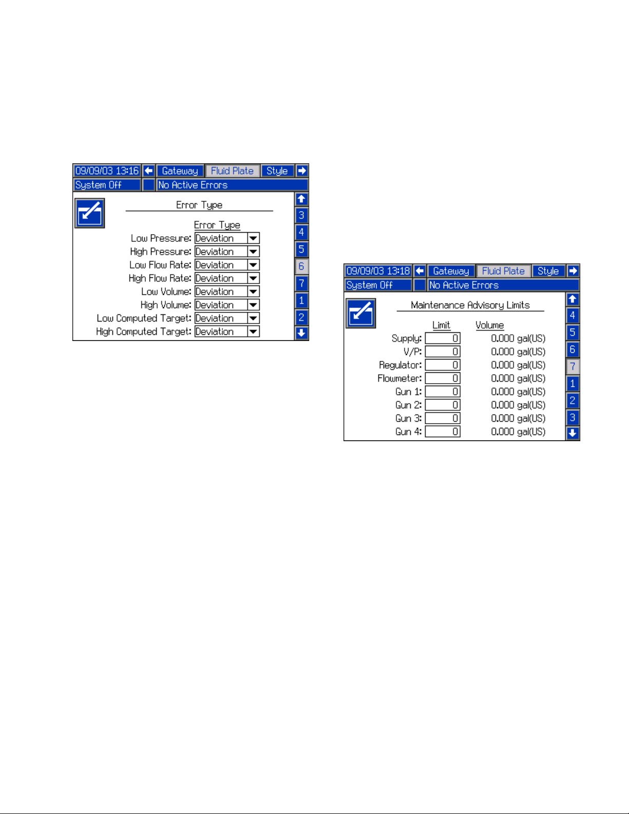
Appendix A - Advanced Display Module (ADM)
Error Type Settings Screen
This screen enables users to set the error type (alarm,
deviation, or none) that will be issued if the pressure,
flow rate, volume, or computed target goes outside the
tolerance settings of the active style. For more information on the purpose of each error, see Jobs, page 37.
Maintenance Advisory Limits Screen
This screen enables users to set volume (or hours) limit
that will trigger a maintenance advisory for the air supply, V/P regulator, fluid regulator, flow meter, and all four
guns.
NOTE: Hours is shown instead of Volume for fluid
plates without a flow meter.
The Volume (or Hours) column displays the current
totalizer value. If this value exceeds the set limit, the
value will turn red and a maintenance advisory is issued.
See Maintenance Screen, page 97, for more information about maintenance totalizers.
313377L 93
Page 94

Appendix A - Advanced Display Module (ADM)
Style Setup Screen
This screen enables users to set up to 256 styles. Press
to access the style setup fields. Enter the style
number in the Style field, the target volume in the Volume field, and the tolerance percentage in the Tolerance field. Enter the precharge mode and parameters.
NOTE: The number of possible styles is dependent
on the model type.
To enter the style name, press while in the Style
Name field. See Keyboard Screen, page 94, for
instructions on using the keyboard screen to enter the
style name.
Keyboard Screen
Use all four arrow buttons to select each letter; press
to enter the letter. To back space, press . To
delete the entire style name entered, press . To
enter the style name, press . To cancel the entry
and exit the keyboard screen, press .
94 313377L
Page 95

Appendix A - Advanced Display Module (ADM)
Current Dispense
Control Mode
Outlet Pressure
Current Command
Value
Flow Rate
(systems with flow
meters)
Inlet Pressure
(non-heated systems)
Command Voltage
(Displays only when
Command Cable or
Gateway is selected as
the Command Value
Source; see Fluid Plate
Setup Screens, page
91.)
Run Mode
Run mode screens are divided into four sections: home,
error reports, job reports, and preventative mainte-
nance. While in Setup mode press to enter Run
mode. Press to navigate through the Run
mode screens.
Home Screens
There are two home screens: one for the fluid plate and
one for the control center. Press to scroll
through the home screens.
Home Screen 1 - Fluid Plate
This screen displays the current dispense control mode
used, the current pressure, and the current style being
dispensed. It also displays the target dispense volume,
the actual dispense volume, and the requested dispense volume.
From this screen users can adjust the bead scale and
enter maintenance mode. Press and to
change the bead scale. Press to enter mainte-
nance mode.
The PCF system has two operating modes:
• Dispense mode – enables the module to begin dispensing when it receives a command from the automation unit.
• Maintenance mode – enables the module to begin
dispensing when the user presses the manual dispense button. Dispense parameters and duration
depend on the selected control.
Dispensing continues for as long as the manual dis-
pense button is pressed.
313377L 95
Page 96

Appendix A - Advanced Display Module (ADM)
Dispense Control Modes
The PCF system has four fluid dispensing control
modes.
• Bead Control – the control unit measures the flow
rate of the material being dispensed. The regulator
outlet pressure is varied to control the fluid flow rate
to the requested value. Use the bead control when a
consistent bead size is required.
• Shot Control – the regulator outlet pressure is controlled to the requested value. The dispense valve is
closed when the target volume is reached or when
the automation controller provides a signal.
• Pressure Control – the regulator outlet pressure is
controlled to the requested value. Use the pressure
control mode if the system does not include a flow
meter.
• Full Open Control – the PCF system does not control fluid pressure or flow. Instead the regulator
opens to allow for recirculation applications.
Maintenance Mode
Home Screen 2 - Control Center
NOTE: Users must be out of maintenance mode in
home screen 1 to scroll to home screen 2.
This screen enables users to view and monitor the current status of the robot outputs and inputs. An X is displayed in the check boxes if the robot is using a style
strobe, when the dispense completes, for each dispense
trigger used, when the dispenser is ready, when the dispense is in process, if there are no alarms or errors, and
when the dispense volume is correct.
This screen also displays the current dispense style,
command voltage, current number of errors or error
number, and the amount of volume dispensed.
Press from the dispense control mode screen to
enter maintenance mode. Maintenance mode enables
users to change the control mode, volume to be dispensed, target pressure, and number of dispense valves
used in the system.
NOTE: Volume, pressure, and dispense valve
options change according to mode.
See Maintenance Mode Operation, page 34, for
instructions on changing the control mode, target pressure, and number of dispense valves used.
96 313377L
Page 97

Appendix A - Advanced Display Module (ADM)
Error Report Screens
There are nine error report screens that display a
chronological list of system errors. These screens display the last 140 errors. Each error report screen displays the date, time, error code, and description for each
error. See Errors, page 55, for more information on
errors, a list of error codes, and information on error
troubleshooting.
Press to scroll through each error report
screen.
Maintenance Screen
This screen enables users to view the maintenance
totalizers for each system component and the limits set
that will trigger a maintenance advisory.
Maintenance totalizers keep track of the total volume (or
hours) that each system component has been running.
If the totalizer value exceeds the set limit, the totalizer
value will turn red and a maintenance advisory is issued.
The limits are set in the Maintenance Advisory Limits
Screen, page 93, for the air supply, V/P regulator, fluid
regulator, flow meter, and all four guns.
NOTE: If a flow meter is not included in the system,
this screen shows hours instead of volume and the
flow meter entry is grayed out.
Job Report Screens
There are 21 job report screens that store and display a
chronological list of jobs performed by the system. Each
job record includes the date and time the job was completed; the style dispensed; the error percentage; and
the target, requested, and actual dispense volumes.
Press to scroll through each job report
screen.
313377L 97
Page 98

Appendix B - Discrete Gateway Module (DGM) Connection Details
Appendix B - Discrete Gateway Module (DGM)
Connection Details
D-Sub Cable 123793
The cable length of the interface cable assembly 123793 is 50 ft (15.2 m). The following table identifies the cable
interface signals.
NOTE: See Appendix D - I/O Signal Descriptions, page 111, for I/O signal descriptions.
Wire Color Description Pin Type
Green/Yellow Isolated Logic Power Supply Supply 51 + 27
Gray Isolated Logic GND Supply 70
Blue/Green Dispense Ready Digital Output 9
Brown/Green Dispense No Error Digital Output 11
Blue/Orange Dispense In Process Digital Output 12
White Dispense Purge Digital Output 15
Blue Dispense Remote Start Digital Output 16
White/Yellow Style Bit 1 Digital Input 52
Blue/Yellow Style Bit 2 Digital Input 53
Brown/Yellow Style Bit 3 Digital Input 54
Black/Red Style Bit 4 Digital Input 55
White/Red Style Strobe Digital Input 56
Blue/Red Dispense Complete Digital Input 57
Brown/Red Error Reset Digital Input 58
Black Remote Start/Purge Digital Input 59
D-Sub
Pin No.
Black/Gray Dispense Gun 1 Digital Input 73
Brown/Orange Dispense Gun 2 Digital Input 74
Brown Command Value Analog Input 1
Black/Yellow Command Value GND Analog Input 2
White/Gray N/C 3
Blue/Gray N/C 21
Brown/Gray N/C 23
White/Orange Dispense Gun 3 Digital Input 75
Black/Orange Dispense Gun 4 Digital Input 76
Black/Green Digital CMD 1 Digital Input 77
White/Green Digital CMD 2 Digital Input 78
Orange N/C N/C
98 313377L
Page 99

Appendix B - Discrete Gateway Module (DGM) Connection Details
D-Sub Cable 123792 and Breakout Board 123783
The cable length of the interface cable assembly 123792 is 50 ft (15.2 m). The following table identifies the pin
assignments for the 78-pin breakout board.
NOTE: See Appendix D - I/O Signal Descriptions, page 111, for I/O signal descriptions.
D-Sub Pin No. Description Pin Type Voltage (Vdc)
1 Command Value Analog In 0-10
2 Command Value GND Analog In GND 0
3
4
5
6
7
8
9 Dispense Ready Digital Out - Bank 1 0 - voltage connected to Pin 27
10 Dispense Alarm/Error on Data Digital Out - Bank 1 0 - voltage connected to Pin 27
11 Dispense Error Digital Out - Bank 1 0 - voltage connected to Pin 27
12 Dispense In Process Digital Out - Bank 1 0 - voltage connected to Pin 27
13 Dispense Volume OK Digital Out - Bank 1 0 - voltage connected to Pin 27
14
15 Dispense Purge Digital Out - Bank 1 0 - voltage connected to Pin 27
16 Dispense Remote Start Digital Out - Bank 1 0 - voltage connected to Pin 27
17 Data 1* Digital Out - Bank 2 0 - voltage connected to Pin 68
18 Data 2* Digital Out - Bank 2 0 - voltage connected to Pin 68
19 Data 4* Digital Out - Bank 2 0 - voltage connected to Pin 68
20 Data 8* Digital Out - Bank 2 0 - voltage connected to Pin 68
21
22
23
24
25
26
27 Digital Out Supply - Bank 1 Isolated Logic Supply V+ 10-30
28 Data 16* Digital Out - Bank 2 0 - voltage connected to Pin 68
29 Data 32* Digital Out - Bank 2 0 - voltage connected to Pin 68
30 Data 64* Digital Out - Bank 2 0 - voltage connected to Pin 68
31 Data 128* Digital Out - Bank 2 0 - voltage connected to Pin 68
32 Data 256* Digital Out - Bank 3 0 - voltage connected to Pin 69
33 Data 512* Digital Out - Bank 3 0 - voltage connected to Pin 69
34 Data 1024* Digital Out - Bank 3 0 - voltage connected to Pin 69
35 Data 2048* Digital Out - Bank 3 0 - voltage connected to Pin 69
36 Data 4096* Digital Out - Bank 3 0 - voltage connected to Pin 69
313377L 99
Page 100

Appendix B - Discrete Gateway Module (DGM) Connection Details
D-Sub Pin No. Description Pin Type Voltage (Vdc)
37 Data 8192* Digital Out - Bank 3 0 - voltage connected to Pin 69
38 Data 16384* Digital Out - Bank 3 0 - voltage connected to Pin 69
39 Data 32768* Digital Out - Bank 3 0 - voltage connected to Pin 69
40
41
42
43
44
45
46
47
48
49
50
51 Isolated Logic Power Supply Isolated Logic Supply V+ 10-30
52 Style Bit 1 Digital In 0-30
53 Style Bit 2 Digital In 0-30
54 Style Bit 3 Digital In 0-30
55 Style Bit 4 Digital In 0-30
56 Style Strobe Digital In 0-30
57 Dispense Complete Digital In 0-30
58 Error Reset Digital In 0-30
59 Remote Start/Purge Digital In 0-30
60
61
62
63
64
65
66
67
68 Digital Out Supply - Bank 2 Isolated Logic Supply V+ 10-30
69 Digital Out Supply - Bank 3 Isolated Logic Supply V+ 10-30
70 Isolated Logic GND Isolated Ground 0
71
72
73 Dispense Gun 1 Digital In 0-30
74 Dispense Gun 2 Digital In 0-30
75 Dispense Gun 3 Digital In 0-30
76 Dispense Gun 4 Digital In 0-30
77 Digital CMD 1 Digital In 0-30
78 Digital CMD 2 Digital In 0-30
* 16-bit data outputs contain either volume or error information depending on state of dispense alarm/error on data.
100 313377L
 Loading...