

Page 1

REPAIR
SP, SPX
Airless Paint Sprayers
Important Safety Instructions
Read all warnings and instructions in this
manual. Save these instructions.
3000 psi (207 bar, 20.7 MPa) Maximum Working Pressure
120 Vac
826031, A
826032, A
309711
Rev. B
Related manuals
Table of Contents
Component Function and Identification 3. . . . . . . . . . . .
Grounding 5. . . . . . . . . . . . . . . . . . . . . . . . . . . . . . . . . . . . .
Troubleshooting 5. . . . . . . . . . . . . . . . . . . . . . . . . . . . . . . .
General Repair Information 4. . . . . . . . . . . . . . . . . . . . . .
Spin Test 10. . . . . . . . . . . . . . . . . . . . . . . . . . . . . . . . . . . . .
Motor Brush Replacement 10. . . . . . . . . . . . . . . . . . . . .
On/Off Switch Replacement 12. . . . . . . . . . . . . . . . . . . .
826031
309665. . . . . . .
309045; SP. . . . . . .
309639; SPX. . . . . . .
309716. . . . . . .
Pressure Control Repair 14. . . . . . . . . . . . . . . . . . . . . . .
Drive Housing Replacement 17. . . . . . . . . . . . . . . . . . . .
Motor Replacement 18. . . . . . . . . . . . . . . . . . . . . . . . . . . .
Displacement Pump Replacement 19. . . . . . . . . . . . . . .
Technical Data 20. . . . . . . . . . . . . . . . . . . . . . . . . . . . . . . .
Graco Phone Number 20. . . . . . . . . . . . . . . . . . . . . . . . . .
309060; SP. . . . . . .
309053; SPX. . . . . . .
TI0051c
GRACO INC. P.O. BOX 1441 MINNEAPOLIS, MN 55440–1441
COPYRIGHT 2003, GRACO INC.
Graco Inc. is registered to I.S. EN ISO 9001
Page 2
WARNING
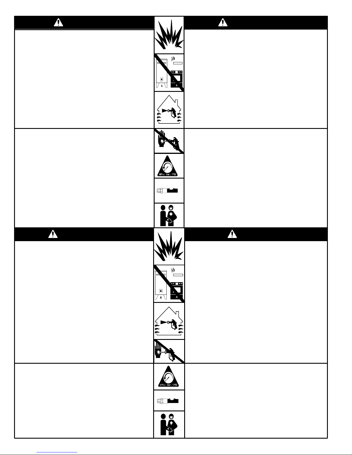
Fire and explosion hazard: Solvent and paint fumes can ignite or
explode.
To help prevent a fire and explosion:
Use only in an extremely well ventilated area.
Eliminate all ignition sources; such as pilot lights, cigarettes and
static arcs from plastic drop cloths. Do not plug or unplug power
cords or turn lights on or off in spray area.
Ground Sprayer, object being sprayed, paint and solvent pails.
Hold gun firmly to side of grounded pail when triggering into pail.
Use only conductive airless paint hose.
Do not use 1,1,1–trichloroethane, methylene chloride, other
halogenated hydrocarbon solvents or fluids containing such
solvents in pressurized aluminum equipment. Such use could
result in a chemical reaction, with the possibility of explosion.
ADVERTÊNCIA
Poderá ocorrer incêndio e explosão quando for pulverizado ou injetado
líquido inflamável numa área onde houver má circulação de ar; vapores
inflamáveis poderão incendiar-se a partir de uma chama ou fagulhas a
descoberto.
Para ajudar a evitar incêndio e explosão:
Utilize no exterior ou numa área muito bem ventilada.
Não utilize 1,1,1–tricloroetano, cloreto de metileno, outros solventes de
hidrocarbonetos halogenados ou líquidos contendo tais solventes em
equipamento de alumínio pressurizado. Tal utilização poderá resultar
numa reação química, com possibilidade de explosão.
Retire, elimine ou desligue todas as fontes de ignição; coloque fita
adesiva na tomada da parede. Não fume na área de pulverização.
Nunca abasteça o depósito de combustível com o motor em funciona-
mento ou quente.
Ponha em contato com a terra o pulverizador, o objeto a ser pulveriza-
do, e os baldes de tinta e de solventes.
Segure a pistola firmemente de encontro ao lado de um balde em contato
com a terra, quando estiver descarregando para dentro do mesmo.
Utilize somente tubos flexíveis condutores para pintura a alta pressão.
Nunca faça funcionar o motor numa área fechada.
Fluid injection and high pressure hazard: High pressure spray or
leaks can inject fluid into the body.
To help prevent injection, always:
Engage trigger safety latch when not spraying.
Keep clear of nozzle and leaks.
Never spray without a tip guard.
Do PRESSURE RELIEF if you stop spraying or begin servicing
sprayer.
Do not use components rated less than sprayer Maximum
Working Pressure
Never allow children to use this unit.
If high pressure fluid pierces your skin, the injury might look like
“just a cut”. But it is a serious wound! Get immediate medical attention.
MISE EN GARDE
Risque d’incendie et d’explosion imminent pendant la pulvérisation
ou le rinçage à pression de fluides inflammables dans une zone à mauvaise circulation d’air et en présence de gaz inflammables pouvant
s’allumer par une flamme nue ou des étincelles.
Pour éviter les risques d’incendie et d’explosion:
Manipuler les fluides à l’air libre ou dans une zone extrêmement
bien aérée.
Ne jamais utiliser de trichloroéthane 1,1,1, de chlorure de méthylène,
d’autres solvants à base d’hydrocarbures halogénés, ni de produits
contenant de tels solvants dans un équipement sous pression en
aluminium. Cela pourrait provoquer une réaction chimique avec risque
d’explosion.
Retirer, éteindre ou déboucher toute source d’inflammation, recouvrir
tout interrupteur mural avec du ruban adhésif. Ne pas fumer dans la
zone de pulvérisation.
Ne jamais remplir le réservoir d’essence lorsque le moteur est chaud
ou en marche.
Mettre à la terre le pulvérisateur, l’objet à pulvériser ainsi que les
seaux de peinture et de solvants.
Tenir le pistolet fermement contre la paroi d’un seau mis à la
terre lorsqu’on pulvérise dans le seau.
N’utiliser qu’un flexible pour peinture pulvérisée sans air.
Ne jamais mettre en marche un moteur dans une zone fermée.
A injeção de líquido é um ferimento grave! Se o líquido a alta pressão penetrar na sua pele, o ferimento poderá parecer “simplesmente
um corte”. Mas é um ferimento grave! Procure o médico imediatamente.
Para ajudar a evitar injeção de líquido, faça sempre o seguinte:
Engate o trinco de segurança do gatilho quando não estiver pulveri-
zando.
Sempre aponte a pistola para longe de você mesmo(a) ou de outras
pessoas.
Alivie a pressão antes de verificar ou reparar qualquer vazamento.
Alivie a pressão quando desligar o pulverizador ou parar de pulverizar.
Não utilize componentes classificados para uma pressão nominal
inferior à pressão máxima de trabalho dos sistemas.
Nunca permita que crianças utilizem esta unidade. Se sofrer algum
ferimento durante a utilização deste equipamento, procure o médico
imediatamente.
ADVERTENCIA
Pueden ocurrir incendios y explosiones cuando se pulveriza fluido inflamable o cuando se lava con este tipo de fluido en un área donde la
circulación de aire es deficiente y los vapores inflamables se pueden encender al contacto con el fuego o chispas.
Para prevenir incendios y explosiones:
Use en espacios abiertos o en un área muy bien ventilada.
No utilice nunca tricloretano–1,1,1, cloruro de metileno, u otros di-
solventes a base de hidrocarburos halógenos o fluidos que contengan
tales disolventes en un equipo a presión de aluminio. El uso de estas
sustancias puede provocar una intensa reacción química, con riesgos
de explosión.
Retire, apague o desconecte todas las fuentes de ignición; asegure el
interruptor de la pared con cinta. No fume en el área de pulverización.
Nunca llene el estanque de combustible mientras el motor esté en
marcha o caliente.
Ponga a tierra el pulverizador, el objeto que recibe el chorro pulverizado,
las cubetas de pintura y disolvente.
Sostenga firmemente la pistola a un lado de la cubeta puesta a
tierra cuando dispare dentro de ella.
Use solamente mangueras para pintura conductora sin aire.
Nunca haga andar el motor dentro de un área cerrada.
L’injection de fluide constitue une lésion grave! Si un fluide haute
pression perce la peau, la blessure peut paraître comme une
«simple coupure». Mais il s’agit bien d’une lésion grave! Consulter
immédiatement un médecin.
Pour éviter les risques d’injection, toujours:
Bloquer le loquet de sécurité de la gâchette à la fin de la pulvérisation.
Pointer le pistolet loin de soi-même et toute autre personne à proximité
Décharger la pression avant de vérifier ou réparer une fuite.
Décharger la pression après la mise hors tension du pulvérisateur ou
à la fin de la pulvérisation.
Ne pas utiliser de composants dont la pression nominale est inférieure
à la pression maximale de service du système.
Ne jamais permettre aux enfants d’utiliser cet appareil. En cas de blessure pour avoir utilisé cet appareil, consulter immédiatement un médecin.
2 309711
¡La inyección de fluido en la piel es una lesión seria! Si fluido de
alta presión le penetra la piel, la lesión podría parecer “sólo un
corte”. ¡Es una lesión seria! Consulte de inmediato al médico.
Para prevenir la inyección en la piel, siempre:
Enganche el seguro del gatillo cuando no use el pulverizador.
No apunte la pistola ni a sí mismo ni a los demás.
Alivie la presión antes de inspeccionar o reparar cualquier filtración.
Alivie la presión cuando apague el pulverizador o deje de usarlo.
No use componentes cuya capacidad nominal sea inferior a la
presión máxima de operación del sistema.
No permita que niños usen esta unidad. Si se lesiona usando este
equipo, sométase de inmediato a tratamiento médico.
Page 3
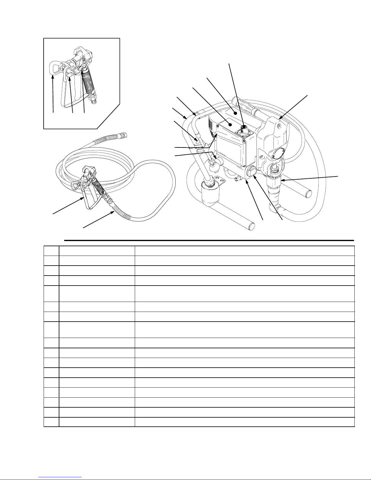
Component Identification and Function
H
A
J
V
U
PR
S
T
K
F
B
D
N
E
G
M
TI0051
Fig. 1
A Motor DC motor, permanent magnet, fan cooled
B Drive Assembly Transfers power from DC motor to displacement pump
D Displacement Pump Transfers fluid to be sprayed from source through spray gun
E Fluid Outlet Spray gun is connected here
F Prime Valve Used to prime and drain sprayer (also relieves fluid outlet pressure) when
open
G Fluid Filter (optional) Final filter of fluid to spray gun
H Pressure Adjusting Knob Controls fluid outlet pressure
J Pressure Control Controls motor speed to maintain fluid outlet pressure at displacement pump
outlet. Works with pressure adjusting knob.
K ON/OFF Switch Power switch that controls main power to sprayer
M 50 ft (15 m) Main Hose 1/4 in. ID, grounded, nylon hose with spring guards on both ends
N Spray Gun High pressure spray gun with gun safety latch
P RAC IV Switch Tip Uses high pressure fluid to clear tip clogs without removing tip from spray gun
R Tip Guard Tip guard reduces risk of injection injury
S Gun Safety Latch Gun safety latch inhibits accidental triggering of spray gun
T Power Cord Rack Holds wrapped power cord for storage
U Suction Hose Transfers fluid to be sprayed from source to pump
V Drain Tube Fluid outlet used to drain and prime the sprayer
8050A
3309711
Page 4
General Repair Information
Pressure Relief Procedure
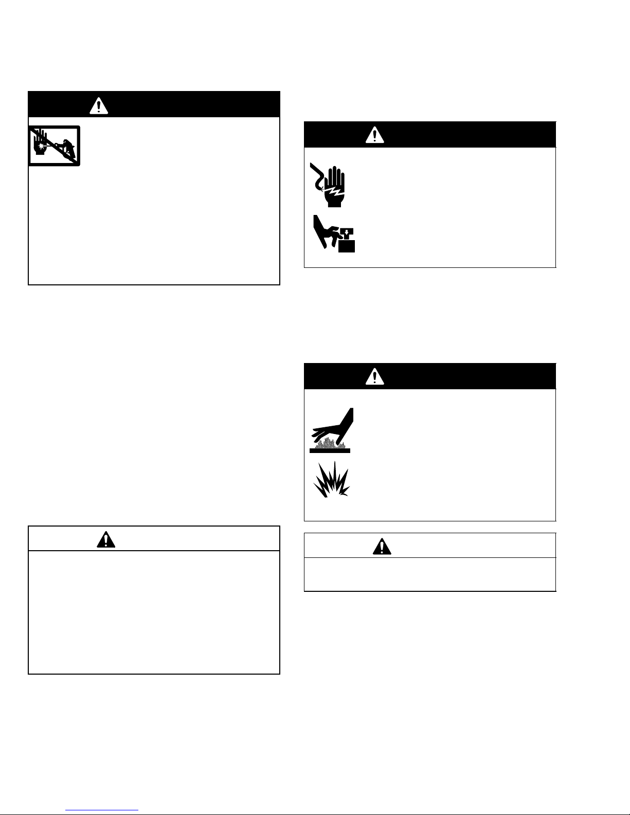
WARNING
INJECTION HAZARD
System pressure must be manually
relieved to prevent system from starting
or spraying accidentally. Fluid under high
pressure can be injected through skin and cause
serious injury. To reduce risk of injury from injection, splashing fluid, or moving parts, follow Pres-
sure Relief Procedure whenever you:
are instructed to relieve pressure,
stop spraying,
check or service any system equipment,
or install or clean spray tip.
1. Lock gun safety latch.
2. Turn ON/OFF switch to OFF.
3. Unplug power supply cord.
4. Unlock gun safety latch. Hold metal part of gun
firmly to grounded metal pail. Trigger gun to relieve
pressure.
5. Lock gun safety latch.
6. Open pressure drain valve. Leave pressure drain
valve open until ready to spray again.
If suspected that spray tip or hose is completely
clogged, or that pressure has not been fully relieved
after following steps above, VERY SLOWLY loosen tip
guard retaining nut or hose end coupling to relieve
pressure gradually, then loosen completely. Now clear
tip or hose obstruction.
1. Keep all screws, nuts, washers, gaskets, and
electrical fittings removed during repair procedures. These parts are not normally provided with
replacement assemblies.
WARNING
ELECTRIC SHOCK HAZARD
MOVING PARTS HAZARD
To reduce risk of serious injury, including
electric shock, do not touch moving or
electrical parts with fingers or tools while
testing repair. Shut off and unplug sprayer when inspection is complete. Install all
covers, gaskets, screws and washers
before operating sprayer.
2. Test repair after problem is corrected.
3. If sprayer does not operate properly, review
repair procedure to verify procedure was done
correctly. If necessary, see Troubleshooting Guide,
pages 5 – 9, for other possible solutions.
WARNING
HOT SURFACES HAZARD
EXPLOSION HAZARD
Motor and drive housing may be very hot
during operation and could burn skin if
touched.
Flammable materials spilled on hot, bare
motor could cause fire or explosion.
Have motor shroud in place during
operation to reduce risk of burns, fire or
explosion.
CAUTION
To reduce risk of pressure control malfunction:
Use needle nose pliers to disconnect wire. Never
pull on wire, pull on connector.
Mate wire connectors properly. Center flat blade of
insulated male connector in female connector.
Route wires carefully to avoid interference with
other connections of pressure control. Do not pinch
wires between cover and control box.
4 309711
CAUTION
Do not run sprayer dry for more than 30 seconds to
avoid damaging pump packings.
4. Install motor shroud before operation of sprayer and replace if damaged. Motor shroud prevents
overheating, and protects operator from possible
electrical shock by touching terminals of capacitor.
It can also reduce risk of burns, fire or explosion;
see preceding WARNING.
Page 5
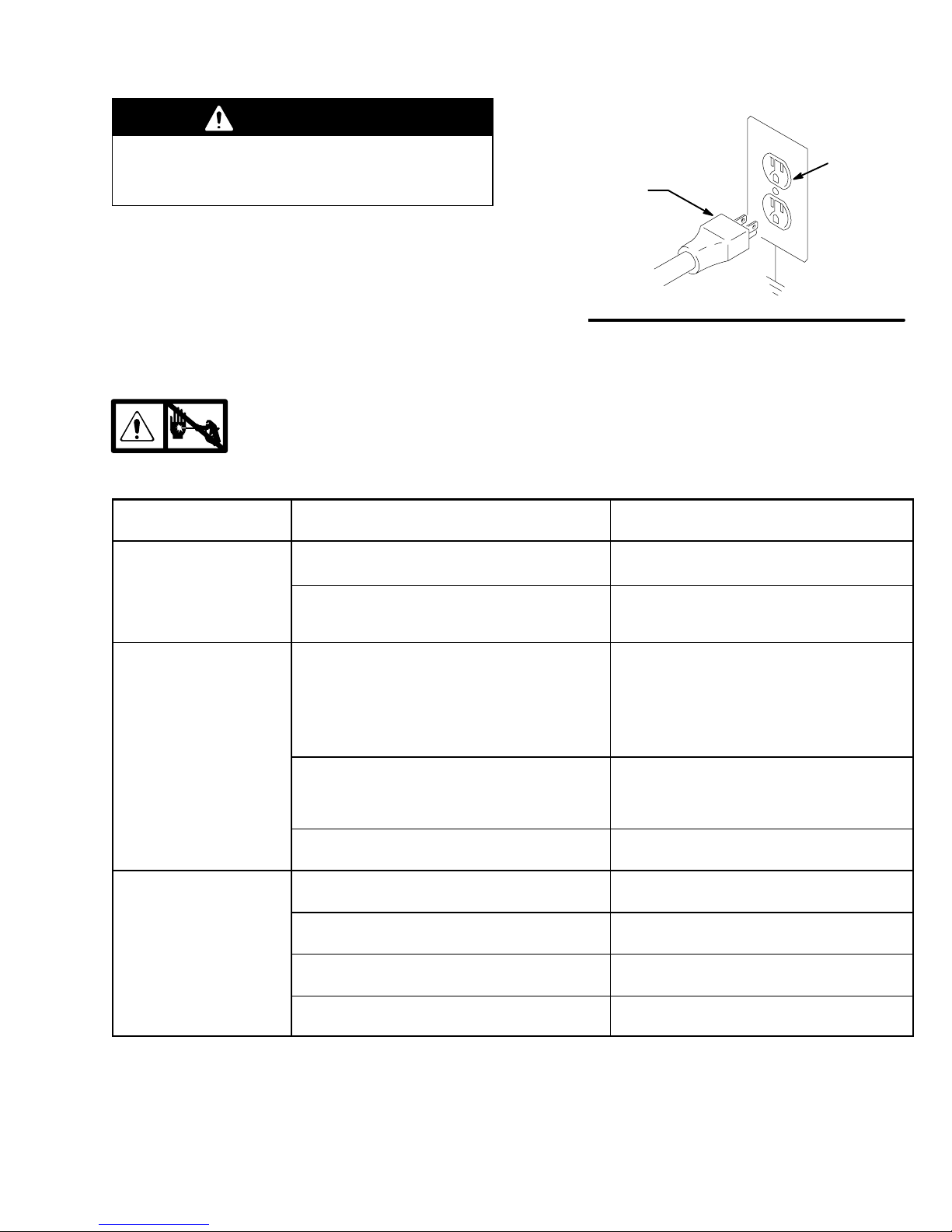
WARNING
Grounding
Improper installation or alteration of grounding plug
results in risk of electric shock, fire or explosion
that could cause serious injury or death.
1. Fig. 2. Both models require a 50/60 Hz, 15A circuit
with a grounding receptacle.
2. Do not alter ground prong or use adapter.
3. A 12 AWG, 3 wires with grounding prong, 300 ft
(90 m) extension cord may be used.
Troubleshooting
Relieve pressure; page 4.
MOTOR WON’T OPERATE
TYPE OF PROBLEM
Basic Fluid Pressure
Problems
WHAT TO CHECK
If check is OK, go to next check
1. Pressure control knob setting. Motor will not run
if at minimum setting (fully counterclockwise).
2. Spray tip or fluid filter may be clogged. 2. Relieve pressure and clear clog or clean fil-
Grounding Plug
Fig. 2
Grounded
Outlets
WHAT TO DO
When check is not OK refer to this column
1. Slowly increase pressure setting to see if motor starts.
ter; refer to separate gun or tip instruction
manual.
Basic Mechanical
Problems
Basic Electrical Problems
1. Pump (13) for frozen or hardened paint. 1. Thaw sprayer if water or water-based paint
2. Displacement pump connecting rod pin (9a).
Pin must be completely pushed into connecting
rod (9) and retaining spring (9b) must be firmly
in groove of pump pin. See Fig. 10.
3. Motor (1). Remove drive housing assembly
(10). See page 17. Try to rotate fan by hand.
1. Motor control board. Board shuts down and displays error code.
2. Electrical supply:
Meter must read 85–130 Vac
3. Extension cord. Check extension cord continuity with volt meter.
4. Sprayer power supply cord (79). Inspect for
damage such as broken insulation or wires.
has frozen in sprayer. Place sprayer in warm
area to thaw. Do not start sprayer until
thawed completely. If paint hardened (dried)
in sprayer, replace pump packings. See
page 19 (Displacement Pump Replace-
ment).
2. Push pin into place and secure with spring retainer.
3. Replace motor (1) if fan won’t turn. See page
18.
1. See Motor Control Board Diagnostics,
page 14.
2. Reset building circuit breaker; replace building fuse. Try another outlet.
3. Replace extension cord.
4. Replace power supply cord.
5309711
Page 6

Troubleshooting
MOTOR WON’T OPERATE (Continued)
TYPE OF PROBLEM
Basic Electrical Problems
(continued)
WHAT TO CHECK
If check is OK, go to next check
5. That motor leads are securely fastened and
properly mated.
6. For loose motor brush lead connections and terminals. See page 10.
7. Brush length which must be 1/2 in. minimum.
See page 10.
NOTE: Brushes do not wear at the same rate on
both sides of motor. Check both brushes.
8. For broken or misaligned motor brush springs.
Rolled portion of spring must rest squarely on
top of brush. See page 10.
9. Motor brushes may be binding in brush holders.
See page 10.
10.Motor armature commutator for burn spots,
gouges and extreme roughness.
See page 10.
11. Motor armature for shorts using armature tester
(growler) or perform spin test. See page 10.
WHAT TO DO
When check is not OK refer to this column
5. Replace loose terminals; crimp to leads. Be
sure terminals are firmly connected.
Clean circuit board terminals. Securely reconnect leads.
6. Tighten terminal screws. Replace brushes if
leads are damaged. See page 10.
7. Replace brushes. See page 10.
8. Replace spring if broken. Realign spring with
brush. See page 10.
9. Clean brush holders. Remove carbon with
small cleaning brush. Align brush leads with
slot in brush holder to assure free vertical
brush movement.
10.Remove motor and have motor shop resurface commutator if possible. See page 18.
11. Replace motor. See page 18.
Refer to wiring diagram on
page 13, to identify test
points (TP).
1. Power supply cord (79). Connect volt meter between N (neutral) and TP1.
Plug in sprayer. Meter must read: 85–130 Vac.
Unplug sprayer.
2. ON/OFF switch (23). Connect volt meter between L and N terminal on ON/OFF switch. Plug
in sprayer and turn ON.
Meter must read 85–130 Vac
3. Motor thermal cutoff switch. Turn sprayer OFF.
Check for continuity between TO1 and TO2 with
ohmmeter.
4. All terminals for damage or loose fit. 4. Replace damaged terminals and reconnect
1. Replace power supply cord.
2. Replace ON/OFF switch. See page 12.
3. If thermal switch is open (no continuity), allow
motor to cool. If switch remains open after
motor cools, replace motor. If thermal switch
closes after motor cools, correct cause of
overheating.
securely.
6 309711
Page 7

Troubleshooting
LOW OR FLUCTUATING OUTPUT
TYPE OF PROBLEM
Low Output 1. For worn spray tip. 1. Follow Pressure Relief Procedure Warn-
WHAT TO CHECK
If check is OK, go to next check
2. Verify pump does not continue to stroke when
gun trigger is released.
3. Filter clogged (If optional filter is installed). 3. Relieve pressure. Check and clean filter.
4. Prime valve leaking. 4. Relieve pressure. Repair prime valve.
5. Suction hose connections. 5. Tighten any loose connections.
6. Electrical supply with volt meter.
Meter must read 85–130 Vac.
Low voltages reduce sprayer performance.
7. Extension cord size and length; must be at least
12 gauge wire and no longer than 300 ft. Longer
cord lengths reduce sprayer performance.
8. Leads from motor to pressure control circuit
board (35) for damaged or loose wires or connectors. Inspect wiring insulation and terminals
for signs of overheating.
9. For loose motor brush leads and terminals. See
page 10.
WHAT TO DO
When check is not OK refer to this column
ing, then replace tip. See your separate
gun or tip manual.
2. Service pump. See page 19.
6. Reset building circuit breaker; replace
building fuse. Repair electrical outlet or try
another outlet.
7. Replace with a correct, grounded extension cord.
8. Be sure male terminal blades are centered
and firmly connected to female terminals.
Replace any loose terminal or damaged
wiring. Securely reconnect terminals.
9. Tighten terminal screws. Replace brushes
if leads are damaged. See page 10.
10.For worn motor brushes which must be 1/2 in.
minimum. See page 10.
11. For broken and misaligned motor brush
springs. Rolled portion of spring must rest
squarely on top of brush.
12.Motor brushes for binding in brush holders. See
page 10.
13.Low stall pressure. 13. Do either or both:
10. Replace brushes. See page 10.
11. Replace spring if broken. Realign spring
with brush. See page 10.
12.Clean brush holders, remove carbon dust
with small cleaning brush. Align brush lead
with slot in brush holder to assure free vertical brush movement.
a. Turn pressure control knob fully
clockwise. Make sure pressure
control knob is properly installed
to allow full clockwise position.
b. Try a new transducer.
14.Motor armature for shorts by using an armature
tester (growler) or perform spin test. See page
10.
14.Replace motor. See page 18.
7309711
Page 8

Troubleshooting
LOW OR FLUCTUATING OUTPUT
TYPE OF PROBLEM
Motor runs and pump strokes 1. Paint supply. 1. Refill and reprime pump.
Motor runs but pump does not
stroke
WHAT TO CHECK
If check is OK, go to next check
2. Intake strainer clogged. 2. Remove and clean, then reinstall.
3. Suction tube or fittings loose. 3. Tighten; use thread sealant or sealing tape
4. To see if intake valve ball and piston ball are
seating properly. See page 19.
5. Leaking around throat packing nut which may
indicate worn or damaged packings. See
page 19.
6. Pump rod damage. 6. Repair pump, page 19.
7. Capacitor failure. Visually inspect capacitor
near terminals. Ensure that orange safety relief plug is intact.
1. Displacement pump pin (9a) (damaged or
missing), page 19.
2. Connecting rod assembly (9) for damage,
page 17.
WHAT TO DO
When check is not OK refer to this column
on threads if necessary.
4. Remove intake valve and clean. Check
balls and seats for nicks; replace if necessary, page 19. Strain paint before using to
remove particles that could clog pump.
5. Replace packings, page 19. Also check
piston valve seat for hardened paint or
nicks and replace if necessary. Tighten
packing nut/wet-cup.
7. Replace capacitor.
1. Replace pump pin if missing. Be sure retainer spring (9b) is fully in groove all
around connecting rod, page 19.
2. Replace connecting rod assembly,
page 17.
3. Gears or drive housing, page 17. 3. Inspect drive housing assembly and gears
for damage and replace if necessary,
page 17.
8 309711
Page 9

Troubleshooting
MOTOR IS HOT AND RUNS INTERMITTENTLY
TYPE OF PROBLEM
Motor is hot and runs intermittently.
ELECTRICAL SHORT
TYPE OF PROBLEM
Building circuit breaker opens
as soon as sprayer switch is
turned on.
CAUTION
Any short in any part of the
motor power circuit will cause
the control circuit to inhibit
sprayer operation. Correctly
diagnose and repair all shorts
before checking and replacing control board.
WHAT TO CHECK
If check is OK, go to next check
1. Determine if sprayer was operated at high
pressure with small tips, which causes low
motor RPM and excessive heat build up.
2. Be sure ambient temperature where sprayer
is located is no more than 90
is not located in direct sun.
WHAT TO CHECK
If check is OK, go to next check
1. All electrical wiring for damaged insulation, and
all terminals for loose fit or damage. Also wires
between pressure control and motor. See page
18.
2. For missing inspection plate gasket (see page
18), bent terminal forks or other metal to metal
contact points which could cause a short.
3. Motor armature for shorts. Use an armature
tester (growler) or perform spin test. See page
10. Inspect windings for burns.
4. Motor control board (35) by performing motor
control board diagnostics on page 14. If diagnostics indicate, substitute with a good board.
F and sprayer
WHAT TO DO
When check is not OK refer to this column
1. Decrease pressure setting or increase tip
size.
2. Move sprayer to shaded, cooler area if possible.
WHAT TO DO
When check is not OK refer to this column
1. Repair or replace any damaged wiring or
terminals. Securely reconnect all wires.
2. Correct faulty conditions.
3. Replace motor. See page 18.
4. Replace with a new pressure control board
(35). See page 14.
Building circuit breaker opens
as soon as sprayer is plugged
into outlet and sprayer is NOT
turned on.
Sprayer quits after sprayer operates for 5 to 10 minutes.
.
CAUTION: Do not perform this check until motor armature is determined to be good. A bad
motor armature can burn out a good board.
1. Basic Electrical Problems on page 5. 1. Perform necessary procedures.
2. ON/OFF switch (23) See page 12. Be sure
sprayer is unplugged! Disconnect wires from
switch. Check switch with ohmmeter. Reading
must be infinity with ON/OFF switch OFF, and
zero with switch ON.
3. For damaged or pinched wires in pressure control. See page 14.
1. Basic Electrical Problems on page 5. 1. Perform necessary procedures.
2. Electrical supply with volt meter.
Meter must read 85–130 Vac.
3. Tightness of pump packing nut. Over tightening
tightens packings on rod, restricts pump action,
and damages packings.
2. Replace ON/OFF switch. See page 12.
3. Replace damaged parts. See page 14.
2. If voltage is too high, do not operate
sprayer until corrected.
3. Loosen packing nut. Check for leaking
around throat. Replace pump packings, if
necessary. See page 19.
9309711
Page 10
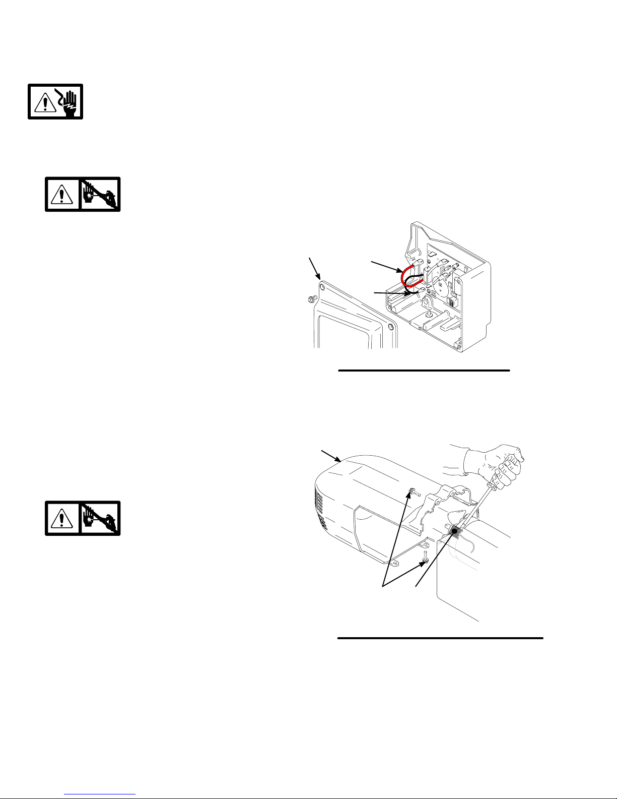
Spin Test
Setup
Electric Shock Hazard; page 4.
To check armature, motor winding and brush electrical
continuity:
1.
2. Remove drive housing; page 17.
3. Fig. 3. Remove pressure control cover (39). Disconnect motor leads (F) and (G).
4. Fig. 4. Remove motor shroud (74).
Relieve pressure; page 4.
Armature Short Circuit Test
Quickly turn motor fan by hand. If no electrical shorts,
motor coasts two or three revolutions before complete
stop. If motor does not spin freely, armature is shorted.
Replace motor; page 18.
Armature, Brushes, and Motor Wiring Open
Circuit Test (Continuity)
1. Connect red and black motor leads together with
test lead. Turn motor fan by hand at about two
revolutions per second.
2. If uneven or no resistance, check for: broken brush
springs, brush leads, motor leads; loose brush
terminal screws, motor lead terminals; worn
brushes. Repair as needed; page 10.
3. If still uneven or no resistance, replace motor;
page 18.
39
F
G
Fig. 3
9578A
Motor Brush Replacement
Motor Brush Removal
Replace brushes worn to less than 1/2 in. Check both
sides. Brush Repair Kit 243215.
1. Read General Repair Information; page 4.
2.
3. Fig. 4. Remove four screws (18) and motor
shroud (74).
4. Pry off two brush caps (A). Tag locations of red (+)
and black (–) motor leads.
5. Fig. 5. Remove brush lead from control box and
discard brush (B).
Relieve pressure; page 4.
(Continued on page 11)
74
Fig. 4
18
A
ti3348a
10 309711
Page 11

Motor Brush Replacement
6. Fig. 5. Insert brush (B). Push clip (A) until it snaps
into place and secures brush.
CAUTION
When installing brushes, follow all steps carefully to
avoid damaging parts.
7. Fig. 5. Install red (+) and black (–) motor leads
according to tags. Install brush lead into control
box and connect to board.
A
B
8. Inspect commutator for excessive pitting, burning
or gouging. A black color on commutator is normal.
Have commutator resurfaced by a motor repair
shop if brushes wear too fast.
9. Test brushes.
a. Remove pump (13); Displacement Pump
Replacement, page 19.
b. With sprayer OFF, turn pressure control knob
fully counterclockwise to minimum pressure.
Plug in sprayer.
c. Turn sprayer ON. Slowly increase pressure
until motor is at full speed.
10. Break in brushes.
Fig. 5
ti3349a
a. Operate sprayer 1 hour with no load.
b. Install pump (13); Displacement Pump Re-
placement, page 19.
11309711
Page 12
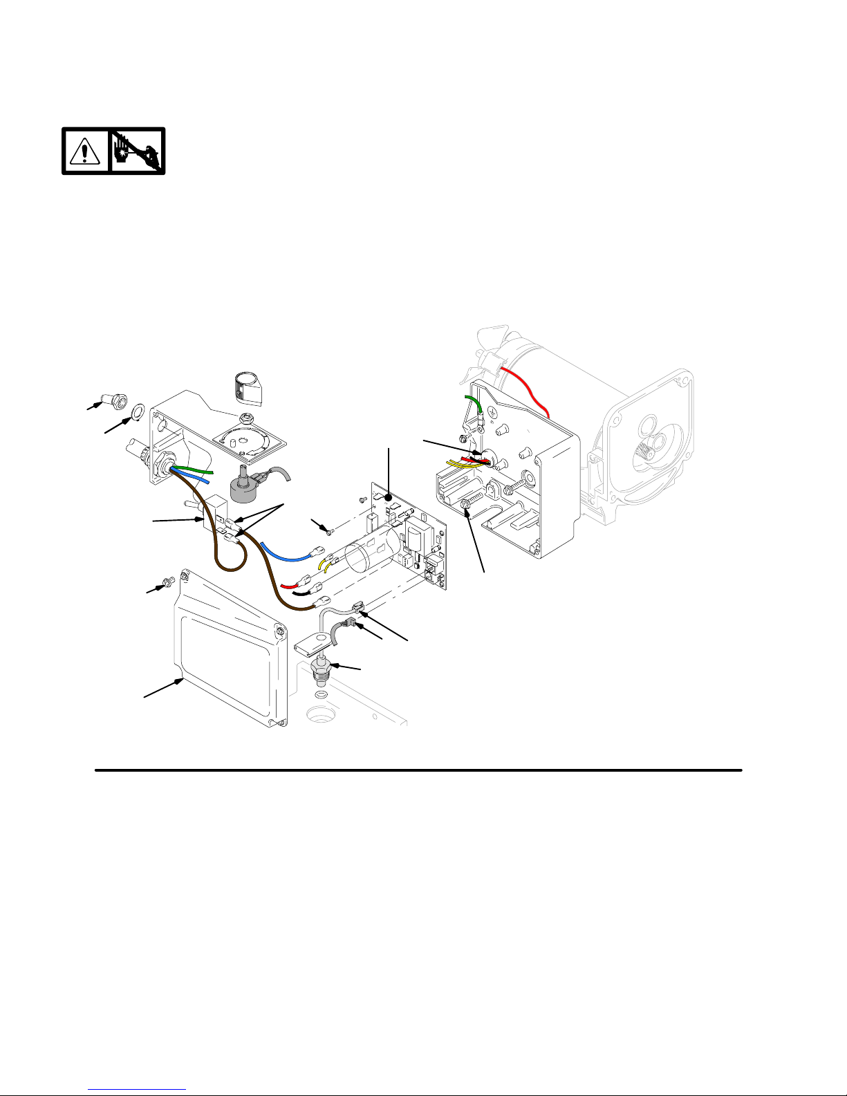
On/Off Switch Replacement
120 Vac; 826031, 826032
Removal
Installation
1.
2. Fig. 6 and 7. Remove four screws (18) and pressure control cover (39).
3. Disconnect two wires (A) from ON/OFF
switch (23).
4. Remove toggle boot (25) and locking ring (24).
Remove ON/OFF switch (23).
25
24
Relieve pressure; page 4.
23
A
36
1. Install new ON/OFF switch (23). Install locking ring
(24) and toggle boot (25).
2. Connect two wires (A) to ON/OFF switch.
3. Install pressure control cover (39) with four
screws (18).
35
37
ti3350a
Fig. 6
18
39
52
22
D
E
12 309711
Page 13
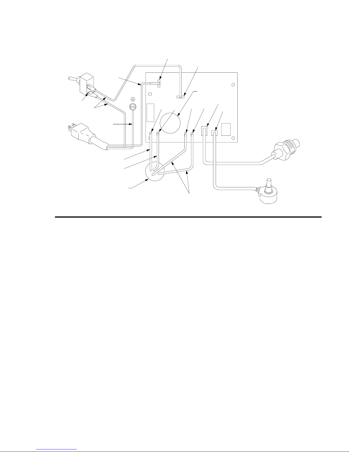
120 Vac
On/Off Switch Replacement
N
Fig. 7
ON/OFF
Switch
Power
Plug
TP1
Black
Green
White
Red (+)
Black (–)
from Motor
M+ M–
L
Capacitor
TO1 TO2
Yellow
Wiring Diagram
826031, A
826032, A
J7
J8
Pressure
Transducer
ti2159a
Potentiometer
13309711
Page 14
Pressure Control Repair
Motor Control Board Diagnostics
Note: Keep a new transducer on hand to use for test.
CAUTION
Do not allow sprayer to develop fluid pressure without transducer installed. Leave drain valve open if
test transducer is used.
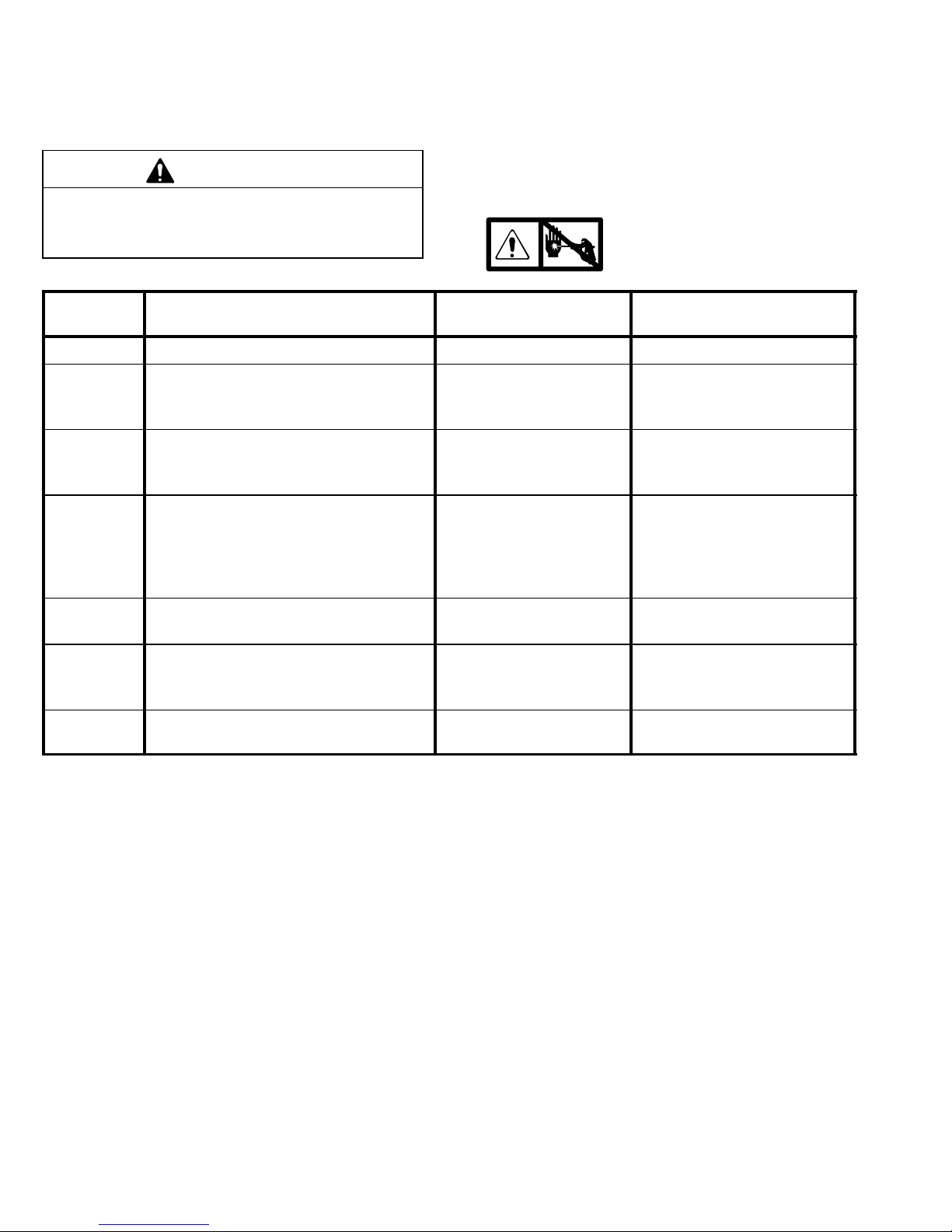
LED
BLINKS
Once Sprayer runs Normal operation Do nothing
Once and
stays ON
Two times
repeatedly
Three times
repeatedly
SPRAYER OPERATION INDICATES WHAT TO DO
Sprayer shuts down and LED stays ON Motor open circuit or bad
Sprayer shuts down and LED continues
to blink two times repeatedly
Sprayer shuts down and LED continues
to blink three times repeatedly
1. Remove four screws (18) and cover (39).
2. Turn ON/OFF switch ON.
3. Observe LED operation and reference following
table:
4.
control board
Run away pressure. Pressure greater than 4500 psi
(310 bar, 31 MPa).
Pressure transducer is
faulty or missing
Relieve pressure and unplug sprayer before servicing control board; page 4.
Check motor brushes and
armature. If OK, replace motor control board.
Replace motor control board.
See following Motor Control
Board procedure.
Check transducer connection.
Open drain valve. Substitute
new transducer for transducer
in sprayer. If sprayer runs,
replace transducer.
Four times
repeatedly
Five times
repeatedly
Six times
repeatedly
Sprayer shuts down and LED continues
to blink four times repeatedly
Sprayer shuts down and LED continues
to blink five times repeatedly
Sprayer shuts down and LED continues
to blink six times repeatedly
Line voltage is too high Check for voltage supply
problems
Too much current Check for locked rotor,
shorted wiring or motor. Repair or replace failed parts.
Motor thermal switch
open circuit
Check for binding in pump or
drive. Check for bad motor.
14 309711
Page 15

Removal
Refer to Fig. 6 and 7.
Pressure Control Repair
Motor Control Board
Installation
1. Clean pad on rear of motor control board. Apply
small amount of thermal compound 073019 to pad.
1.
2. Remove four screws (18) and cover (39).
3. Disconnect at motor control board (35):
Four motor leads: two yellow, black (–)
and red (+).
Two line voltage leads.
Lead (D) from potentiometer.
Lead (E) from transducer.
4. Remove five screws (36) and circuit board (35).
Relieve pressure; page 4.
2. Fig. 6. Install motor control board (35) with five
screws (36).
3. Connect to motor control board (35):
Lead (E) to transducer.
Lead (D) to potentiometer.
Two line voltage leads.
Four motor leads: two yellow, black (–)
and red (+).
4. Install cover (39) with four screws (18).
15309711
Page 16

Pressure Control Repair
Pressure Control Transducer
Removal
Refer to Fig. 6 and 7.
1.
2. Remove four screws (18) and cover (39).
3. Disconnect lead (E) from motor control
board (35).
4. Remove two screws (22) and filter housing (45).
5. Thread transducer lead plastic connector down
through transducer grommet (28).
6. Remove pressure control transducer (52) and
packing o-ring (51) from filter housing.
Installation
1. Install packing o-ring (51) and pressure control
transducer (52) in filter housing (45). Torque to
30–35 ft-lb.
2. Thread transducer lead plastic connector up
through transducer grommet (28).
3. Install filter housing (45) with two screws (22).
4. Connect lead (E) to motor control board (35).
5. Install cover (39) with four screws (18).
Relieve pressure; page 4.
Pressure Adjust Potentiometer
Removal
Refer to Fig. 6 and 7.
1.
2. Remove four screws (18) and cover (39).
3. Disconnect all leads from motor control board (35).
4. Remove five screws (36) and board (35)
5. Remove potentiometer knob (27), sealing shaft nut
(33) and pressure adjust potentiometer (26).
Installation
1. Install pressure adjust potentiometer (26), sealing
shaft nut (33) and potentiometer knob (27).
a. Turn potentiometer fully clockwise.
b. Install knob at full clockwise position.
2. Install board (35) with five screws (36).
3. Connect all leads to motor control board (35).
4. Install cover (39) with four screws (18).
Relieve pressure; page 4.
16 309711
Page 17
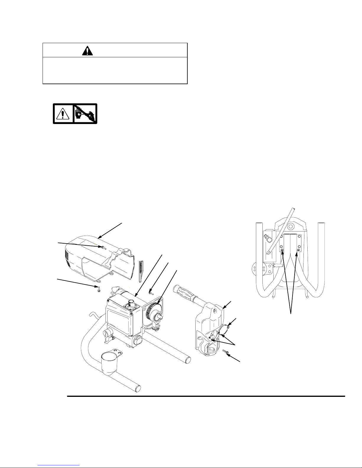
Drive Housing Replacement
CAUTION
Do not drop gear cluster (7) when removing drive
housing (10). Gear cluster may stay engaged in
motor front end bell or drive housing.
Disassembly
1.
Relieve pressure; page 4.
5. Remove two back screws (22).
6. Pull drive housing (10) off of motor (1).
Assembly
1. Push drive housing (10) onto motor (1)
2. Install two front screws (22).
3. Install two back screws (22).
2. Remove pump (13); Displacement Pump Re-
placement, page 19.
3. Fig. 8. Remove two screws (18a).Tip sprayer up.
Remove two screws (18b) and remove shroud
(74).
4. Remove two front screws (22).
74
18a
1
22
18b
4. Fig. 8. Install shroud (74) with two screw (18a).Tip
sprayer up. Install two screws (18b).
5. Install pump (13); Displacement Pump Replace-
ment, page 19.
6. Install new access cover (10a) with two screws
(10b).
7
10
Fig. 8
ti3352a
10a
10b
18b
22
ti0052b
17309711
Page 18
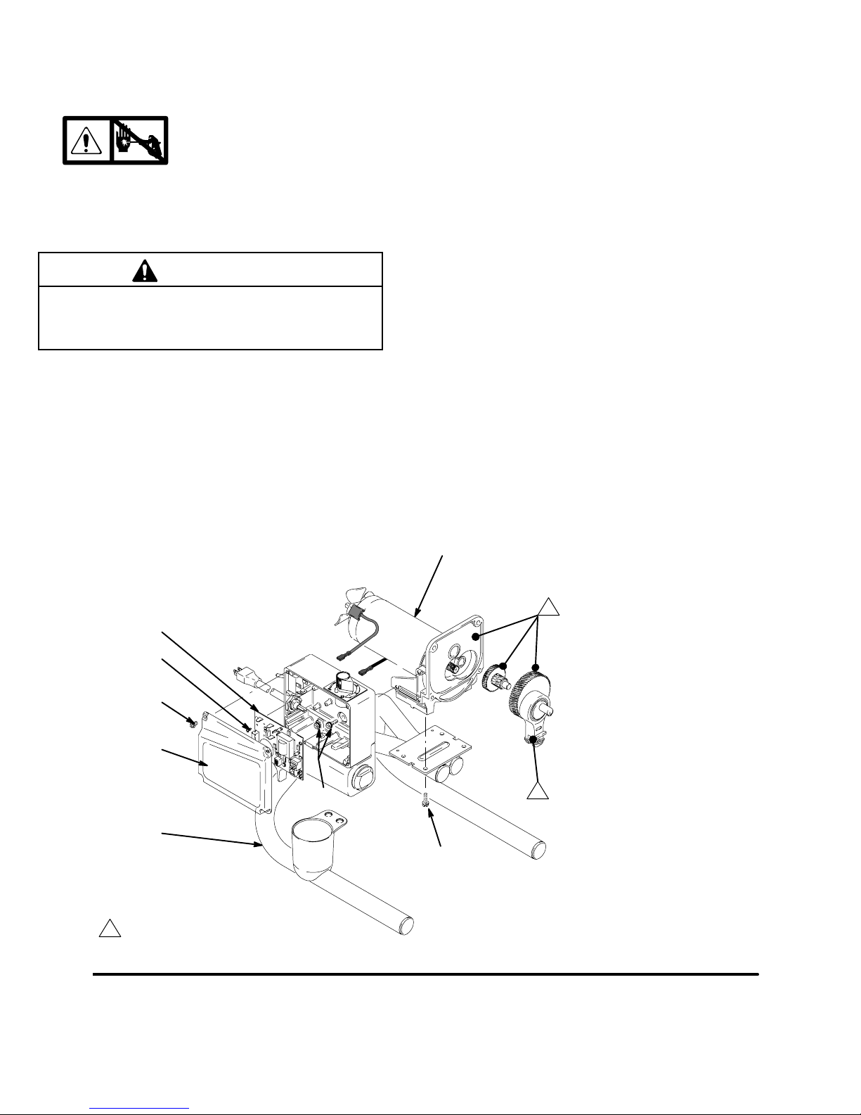
Motor Replacement
Disassembly
1.
2. Remove pump (13); Displacement Pump Re-
placement, page 19.
Relieve pressure; page 4.
CAUTION
Do not drop gear cluster (7) when removing drive
housing (10). Gear cluster may stay engaged in
motor front end bell or drive housing.
3. Remove drive housing (10); Drive Housing Re-
placement, page 17.
4. Remove four screws (18) and cover (39).
5. Disconnect all leads from board (35). Remove five
screws (36) and board.
6. Remove strain relief (37; Fig. 6) and motor fan (2).
7. Remove three screws (22) behind board and
remove control housing (21).
8. Remove four screws (22) and motor (1) from
frame (63).
Assembly
1. Install new motor (1) on frame (63) with four
screws (22).
2. Install control housing (21) with three screws (22).
3. Install strain relief (37; Fig. 6) and motor
fan (2).
4. Install board (35) with five screws (36). Connect all
leads to board (35).
5. Install drive housing (10); Drive Housing Re-
placement, page 17.
6. Install pump (13); Displacement Pump Replace-
ment, page 19.
35
36
18
39
63
1
Liberally apply grease
22
22
1
1
1
ti3351a
ti0054b
Fig. 9
18 309711
Page 19
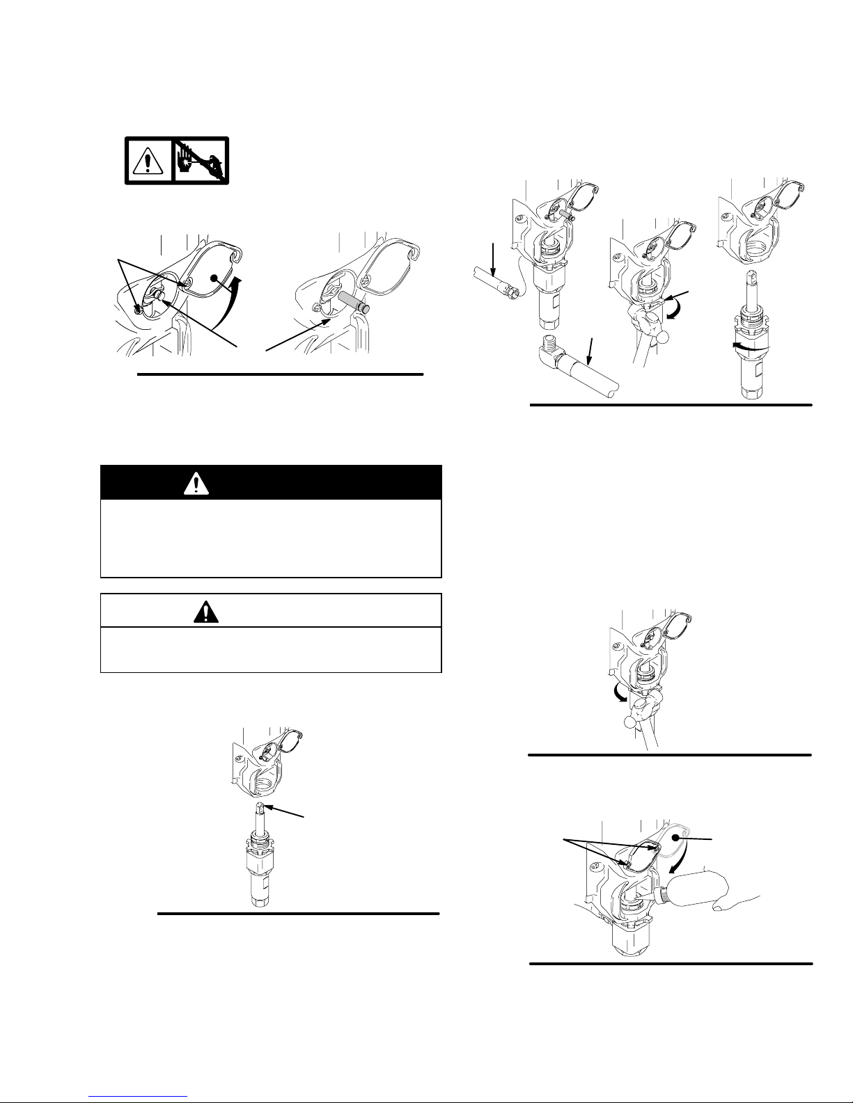
Displacement Pump Replacement
T
Removal
1. Flush pump (13).
2.
3. Fig. 10. Loosen two screws (10b) and rotate
cover (10a).
b
g. 10
4. Cycle pump until pump pin (9a) is in position to be
removed. Remove pump pin (9a).
Relieve pressure; page 4.
10a
9a
9573A
Installation
WARNING
If pin works loose, parts could break off due to
force of pumping action. Parts could project
through the air and result in serious injury or property damage.
5. Fig. 11. Remove suction tube (78) and hose (19).
6. Loosen pump jam nut (12). Unscrew pump.
19
12
78
Fig. 11
4. Screw in pump until threads are flush with drive
housing opening. Align pump outlet to back.
5. Fig. 11. Install suction tube (78) and hose (19).
6. Fig. 13. Screw jam nut (12) up onto pump until nut
stops. Tighten jam nut by hand, then tap 1/8 to 1/4
turn with a 20 oz (maximum) hammer to approximately 75 +/–5 ft-lb (102 Nm).
TI0062
CAUTION
If the pump locknut loosens during operation, the
threads of the drive housing will be damaged.
1. Fig. 12. Extend pump piston rod fully. Apply grease
to top of pump rod at (A) or inside connecting rod.
A
Fig. 12
2. Fig. 10. Install pump pin (9a). Verify retainer spring
(9b) is in groove of pump pin.
3. Push pump up until pump threads engage.
TI0062
Fig. 13
7. Fig. 14. Fill packing nut with Graco TSL until fluid
flows onto top of seal.
10b
Fig. 14
8. Fig. 10. rotate cover (10a); tighten screws (10b).
10a
TI0063
TI0061
19309711
Page 20

Technical Data
100–120V, ∅, A,HzGenerator
Minimum W
1, 7, 50/60 3000 7/8 (653) 680 (180) 0.38 (1.44) 0.019 1/4 in.
Basic Sprayer Wetted Parts: . . . . . . . . . . . . . . . . . . . . . . . . . . .
zinc-plated carbon steel, polyurethane, polyethylene,
stainless steel, PTFE, Delrin
er, UHMWPE, aluminum, tungsten carbide
NOTE: Delrin is a registered trademark of the DuPont Co.
Motor HP (W) Cycles per gallon (li-
ter)
Noise Level
, chrome plating, leath-
Sound Power 87 dB(A)*. . . . . . . . . . . . . . . . . . . . . . . . . .
Sound Pressure 75 dB(A)*. . . . . . . . . . . . . . . . . . . . . . .
* ISO 3744; measured at 3.1 feet (1 m)
Maximum
Delivery gpm
(lpm)
Maximum
Tip size
Fluid Outlet
npsm
Dimensions
Weight lb (kg) Height in. (cm) Length in. (cm) Width in. (cm)
34.5 (15.7) 17.75 (45.1) 14.5 (36.8) 13.5 (34.3)
Graco Phone Number
TO PLACE AN ORDER OR FOR SERVICE, contact your Graco distributor,
or call 1–800–690–2894 to identify the nearest distributor.
All written and visual data contained in this document reflect the latest product information available at the time of publication.
Graco reserves the right to make changes at any time without notice.
International Offices: Belgium, Korea, China, Japan
GRACO INC. P.O. BOX 1441 MINNEAPOLIS, MN 55440–1441
20 309711
This manual contains English
mm 309711
Graco Headquarters: Minneapolis
www.graco.com
PRINTED IN U.S.A. 1/2003, Rev 11/2005
 Loading...