

Page 1
Instructions
®
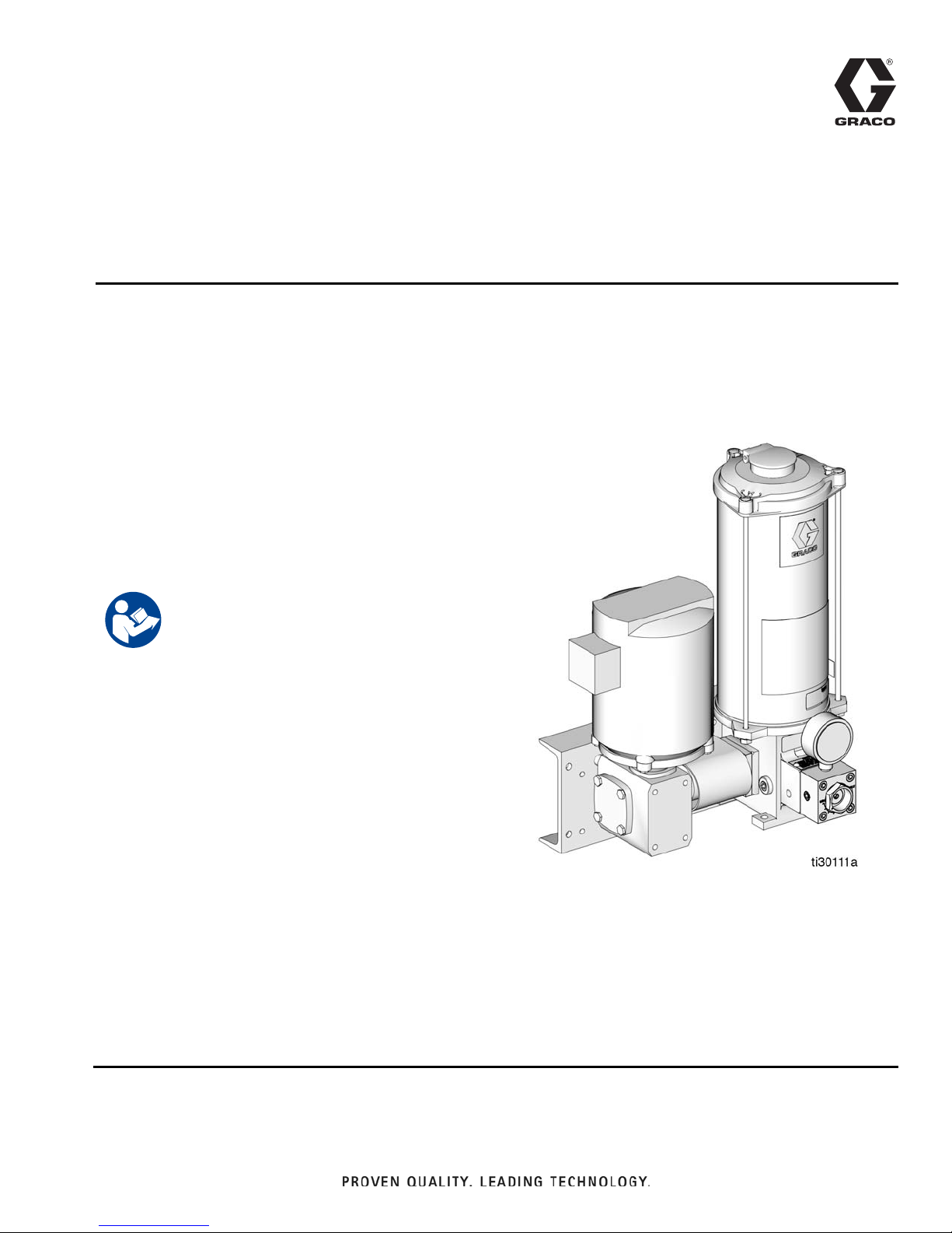
LubeMaster
Floor
Mount or Wall Mount
3A2781A
Pump Package
Provides a constant supply of lubrication to pump components. For professional use only.
Maximum Working Pressure: 5000 psi (340 bar, 34.0 MPa)
The LubeMaster Pump Package includes the following
components:
• Reservoir
• Oil or Grease Pump
EN
See page 6 for part number information.
Important Safety Instructions
Read all warnings and instructions in this manual. Save
these instructions.
Page 2

Table of Contents
Table of Contents
Part Number . . . . . . . . . . . . . . . . . . . . . . . . . . . . . . . 3
Warnings . . . . . . . . . . . . . . . . . . . . . . . . . . . . . . . . . 4
System Identification . . . . . . . . . . . . . . . . . . . . . . . 6
Component Identification . . . . . . . . . . . . . . . . . . . . 7
Reservoirs - Oil or Grease . . . . . . . . . . . . . . . . . 7
Pump . . . . . . . . . . . . . . . . . . . . . . . . . . . . . . . . . . 7
Motors and Drives . . . . . . . . . . . . . . . . . . . . . . . . 7
Installation Instructions . . . . . . . . . . . . . . . . . . . . . 8
Grounding . . . . . . . . . . . . . . . . . . . . . . . . . . . . . . 8
Pressure Relief Valves . . . . . . . . . . . . . . . . . . . . 8
Choosing an Installation Location . . . . . . . . . . . . 8
Pump Installation Procedure . . . . . . . . . . . . . . . . 8
Setup . . . . . . . . . . . . . . . . . . . . . . . . . . . . . . . . . . . . . 9
Filling the Reservoir . . . . . . . . . . . . . . . . . . . . . . 9
System Filling . . . . . . . . . . . . . . . . . . . . . . . . . . 11
Manifold Bleeding . . . . . . . . . . . . . . . . . . . . . . . 11
Adjusting the Clutch Drive . . . . . . . . . . . . . . . . . 11
Standard Pump Adjustment . . . . . . . . . . . . . . . 12
Operation . . . . . . . . . . . . . . . . . . . . . . . . . . . . . . . . 13
Startup . . . . . . . . . . . . . . . . . . . . . . . . . . . . . . . 13
Pressure Relief Procedure . . . . . . . . . . . . . . . . 13
Troubleshooting . . . . . . . . . . . . . . . . . . . . . . . . . . . 14
Maintenance and Repair . . . . . . . . . . . . . . . . . . . . 17
Pumps: Oil and Grease Models . . . . . . . . . . . . 17
Grease Reservoirs . . . . . . . . . . . . . . . . . . . . . . 18
Low-Level Switch Assemblies . . . . . . . . . . . . . . 19
Oil Reservoirs . . . . . . . . . . . . . . . . . . . . . . . . . . 20
Installation After Maintenance . . . . . . . . . . . . . . 24
Drive and Motor . . . . . . . . . . . . . . . . . . . . . . . . . 24
Recommended Lubricants for Enclosed Gear
Reducers . . . . . . . . . . . . . . . . . . . . . . . . . . 24
Alternative AGMA Lubricants . . . . . . . . . . . . . . 24
Parts . . . . . . . . . . . . . . . . . . . . . . . . . . . . . . . . . . . . 25
Grease Reservoirs . . . . . . . . . . . . . . . . . . . . . . . 25
Oil Reservoirs . . . . . . . . . . . . . . . . . . . . . . . . . . 26
Overhead Supply Adapter Assembly . . . . . . . . . 27
Pump Body Assembly . . . . . . . . . . . . . . . . . . . . 28
Clutch Drive Assembly . . . . . . . . . . . . . . . . . . . 29
LubeMaster Pump . . . . . . . . . . . . . . . . . . . . . . . 30
Motorized LubeMaster Pump with Gear Reducer
and Motor (Up to 20 lbs):
Floor Mounting . . . . . . . . . . . . . . . . . . . . . . 31
Motorized LubeMaster Pump with Gear Reducer
and Motor (Up to 20 lbs):
Wall Mounting . . . . . . . . . . . . . . . . . . . . . . . 32
Oil Reservoir 15 Amp Low-Level Assemblies . . 33
Oil Reservoir 10-Watt Low-Level Assemblies . . 33
Grease Reservoir Low-Level Assembly . . . . . . . 34
Technical Data . . . . . . . . . . . . . . . . . . . . . . . . . . . . 35
Dimensions . . . . . . . . . . . . . . . . . . . . . . . . . . . . . . . 37
Reservoirs . . . . . . . . . . . . . . . . . . . . . . . . . . . . . 37
Reservoirs . . . . . . . . . . . . . . . . . . . . . . . . . . . . . 38
Clutch Drive . . . . . . . . . . . . . . . . . . . . . . . . . . . . 39
Clutch Drive . . . . . . . . . . . . . . . . . . . . . . . . . . . . 40
Motorized LubeMaster (Up to 20lbs):
Wall Mounting . . . . . . . . . . . . . . . . . . . . . . . 41
Motorized LubeMaster (Up to 20lbs):
Floor Mounting . . . . . . . . . . . . . . . . . . . . . . 42
Motorized LubeMaster (Up to 20lbs) . . . . . . . . . 43
Graco Standard Warranty . . . . . . . . . . . . . . . . . . . 44
2 3A2781A
Page 3
Part Number
Part Number
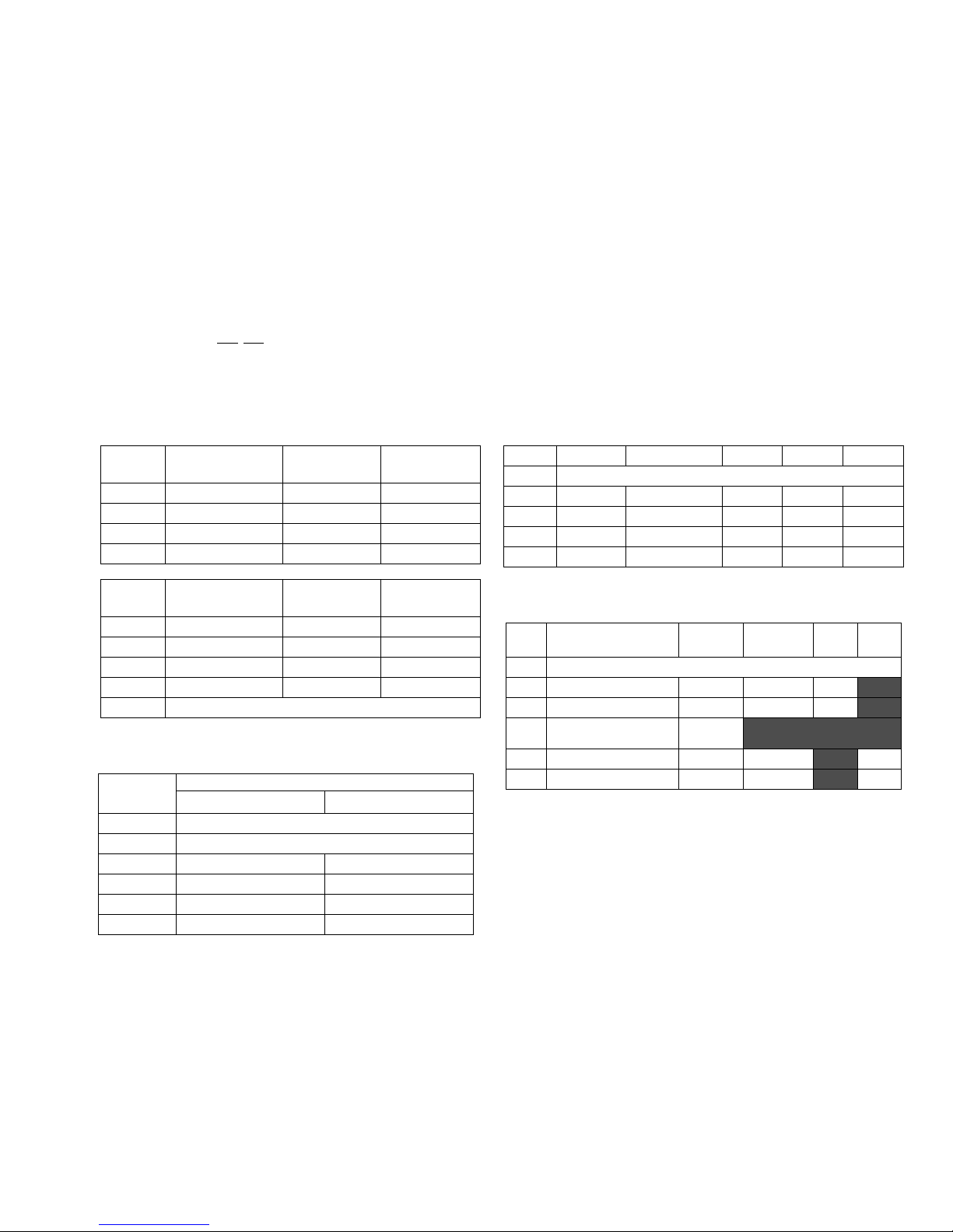
Use the Part Number Key provided below to identify each component included in your LubeMaster Pumping System Part Number.
The Codes associated with each Option (A-D) that make up the Part Number are provided in the tables below. For example, Part
Number - LM1321 is a LubeMaster pump system with a 12 pint plastic oil reservoir. It has a 10:1 reduction ratio and is floor
mounted. It is powered with a 115/230V, 1/2 hp, 1 PH, 60 hz, 1725 RPM motor and does not have a low level switch.
NOTE: Some part number configurations are not available. Contact Graco Customer Service or your local Graco distributor for
assistance.
Par t Key: LM A - B - C - D
Part Example: LM 1 3 2 1
LM = LubeMaster
Option A: Reservoir Options
Code
Code
Reservoir Size:
pints (liters)
1 12 (5.68) Oil Plastic
2 20 (9.46) Oil Plastic
3 12 (5.68) Oil Metal
4 20 (9.46) Oil Metal
Reservoir Size:
pounds (kg)
5 12 (5.44) Grease Plastic
6 20 (9.07) Grease Plastic
7 12 (5.44) Grease Metal
8 20 (9.46 L) Grease Metal
9 No Reservoir, Overhead Supply
Oil or Grease
Oil or Grease
Plastic or
Metal
Plastic or
Metal
Option B: Drive Options
Code
1None
2 Clutch Drive With Arm
3 10:1 Floor Mounting
4 10:1 Wall Mounting
5 60:1 Floor Mounting
6 60:1 Wall Mounting
Reduction Ratio Mounting Option
Description
Option C: Motor Options
Code Voltage Horsepower PH Hz RPM
1None
2 115/230 1/2 1 60 1725
3 230/460 1/2 3 60 1725
4 115/230 1/2 1 60 1140
5 230/460 1/2 3 60 1140
Option D: Low Level Switch Options
Code Size
1
2 12 (5.68 L) Oil X 15
3 20 (9.46 L) Oil X 15
12 and 20 pounds
4
(5.44 and 9.07 kg)
5 12 (5.68 L) Oil X 10
6 20 (9.46 L) Oil X
Oil or
Grease
No low level switch
Grease
SPDT Amps Watts
10
3A2781A 3
Page 4
Warnings
Warnings
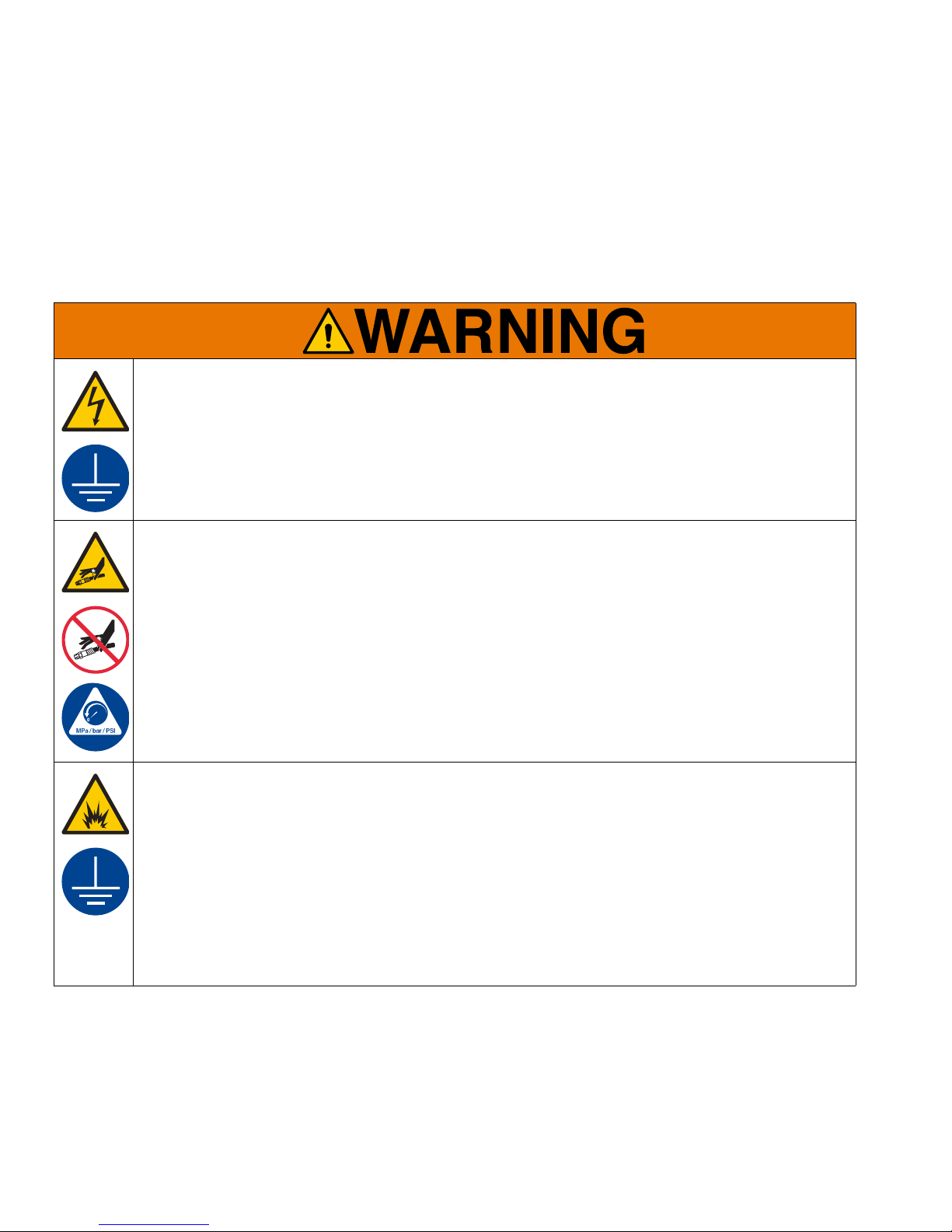
The following warnings are for the setup, use, grounding, maintenance, and repair of this equipment. The exclamation point symbol alerts you to a general warning and the hazard symbols refer to procedure-specific risks. When
these symbols appear in the body of this manual or on warning labels, refer back to these Warnings. Product-specific
hazard symbols and warnings not covered in this section may appear throughout the body of this manual where
applicable.
ELECTRIC SHOCK HAZARD
This equipment must be grounded. Improper grounding, setup, or usage of the system can cause electric shock.
• Turn off and disconnect power at main switch before disconnecting any cables and before servicing
or installing equipment.
• Connect only to grounded power source.
• All electrical wiring must be done by a qualified electrician and comply with all local codes and
regulations.
SKIN INJECTION HAZARD
High-pressure fluid from dispensing device, hose leaks, or ruptured components will pierce skin. This
may look like just a cut, but it is a serious injury that can result in amputation. Get immediate surgical
treatment.
• Do not point dispensing device at anyone or at any part of the body.
• Do not put your hand over the fluid outlet.
• Do not stop or deflect leaks with your hand, body, glove, or rag.
• Follow the Pressure Relief Procedure when you stop dispensing and before cleaning, checking, or
servicing equipment.
• Tighten all fluid connections before operating the equipment.
• Check hoses and couplings daily. Replace worn or damaged parts immediately.
FIRE AND EXPLOSION HAZARD
When flammable fluids are present in the work area, such as gasoline and windshield wiper fluid, be
aware that flammable fumes can ignite or explode. To help prevent fire and explosion:
• Use equipment only in well ventilated area.
• Eliminate all ignition sources, such as cigarettes and portable electric lamps.
• Ground all equipment in the work area.
• Keep work area free of debris, including rags and spilled or open containers of solvent and gasoline.
• Do not plug or unplug power cords or turn lights on or off when flammable fumes are present.
• Use only grounded hoses.
• Stop operation immediately if static sparking occurs or you feel a shock. Do not use equipment until
you identify and correct the problem.
• Keep a working fire extinguisher in the work area.
4 3A2781A
Page 5
Warnings
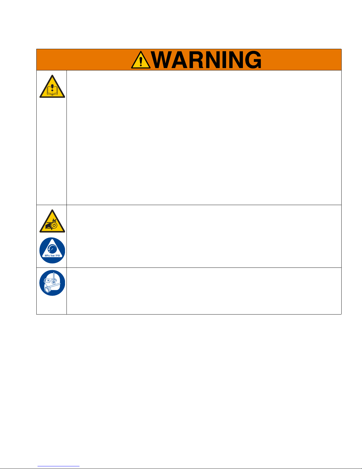
EQUIPMENT MISUSE HAZARD
Misuse can cause death or serious injury.
• Do not operate the unit when fatigued or under the influence of drugs or alcohol.
• Do not exceed the maximum working pressure or temperature rating of the lowest rated system component. See Technical Data in all equipment manuals.
• Use fluids and solvents that are compatible with equipment wetted parts. See Technical Data in all
equipment manuals. Read fluid and solvent manufacturer’s warnings. For complete information about
your material, request Safety Data Sheet (SDS) from distributor or retailer.
• Turn off all equipment and follow the Pressure Relief Procedure when equipment is not in use.
• Check equipment daily. Repair or replace worn or damaged parts immediately with genuine manufacturer’s replacement parts only.
• Do not alter or modify equipment. Alterations or modifications may void agency approvals and create
safety hazards.
• Make sure all equipment is rated and approved for the environment in which you are using it.
• Use equipment only for its intended purpose. Call your distributor for information.
• Route hoses and cables away from traffic areas, sharp edges, moving parts, and hot surfaces.
• Do not kink or over bend hoses or use hoses to pull equipment.
• Keep children and animals away from work area.
• Comply with all applicable safety regulations.
ENTANGLEMENT HAZARD
Rotating parts can cause serious injury.
• Keep clear of moving parts.
• Do not operate equipment with protective guards or covers removed.
• Do not wear loose clothing, jewelry or long hair while operating equipment.
• Equipment can start without warning. Before checking, moving, or servicing equipment, follow the
Pressure Relief Procedure and disconnect all power sources.
PERSONAL PROTECTIVE EQUIPMENT
Wear appropriate protective equipment when in the work area to help prevent serious injury, including
eye injury, hearing loss, inhalation of toxic fumes, and burns. Protective equipment includes but is not
limited to:
• Protective eyewear, and hearing protection.
• Respirators, protective clothing, and gloves as recommended by the fluid and solvent manufacturer.
3A2781A 5
Page 6
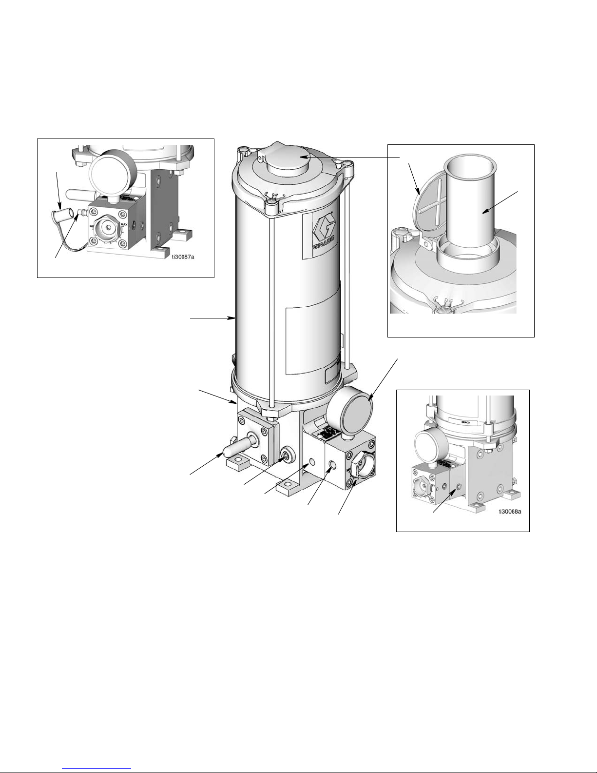
System Identification
11
Oil Model
Grease Model
A
D
B
30
31
C
101
E
F
E
13
12
Side View
System Identification
(Floor Mount Model Shown)
FIG. 1
A Pump Adjustment Nut
B Pump Inlet
CDrive Shaft
D Pressure Gauge
E Drain and Drain Plug (Oil Models: one on each side of
base); (Grease Models: one on the opposite side of the
base from the fill stud (13)
F Pump Outlet
11 Reservoir Assembly (Oil or Grease)
12 Fill Cap (Grease Only)
13 Fill Stud (Grease Only)
30 Fill Cap (Oil Only)
31 Filter Screen (Oil Only)
101 Pump Body
6 3A2781A
Page 7
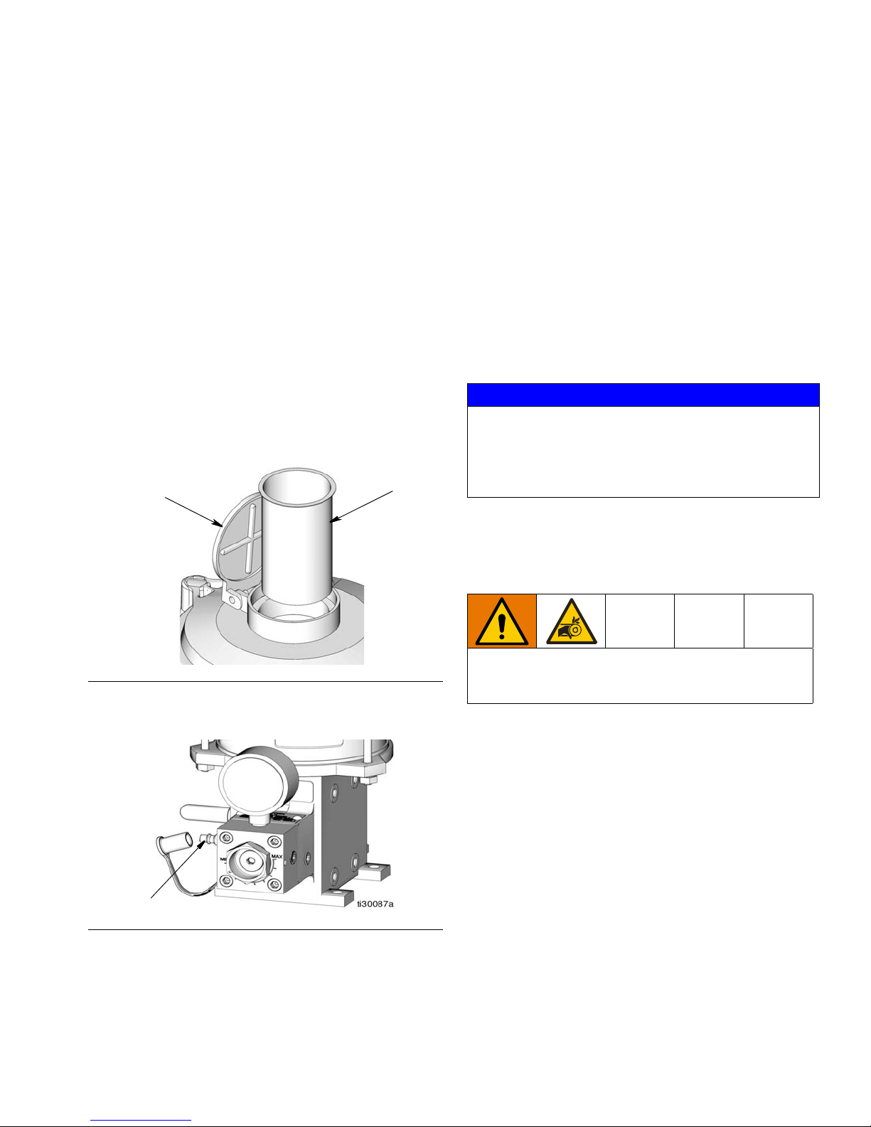
Component Identification
31
30
13
Component Identification
All LubeMaster Pump Packages include the following
components:
• A reservoir (11) for holding the lubricant.
• A standard pump (101).
Reservoirs (11) - Oil or Grease
• Container for holding oil or grease.
• Grease models include a follower plate.
• The reservoir mounts directly to LubeMaster pump.
Oil Reservoirs
• Reservoirs for oil models have a fill cap (30) and
screen (31), located on top (F
IG. 2).
Pump (101)
• The pump can be driven by an electric motor or by a
rotating or oscillating machine motion.
• The pump must always be installed with the reservoir (11) in a vertical position to ensure proper operation.
• Always use lockwashers with mounting bolts and
make certain that the bolts are properly torqued.
Motors and Drives
Gear Reducer
NOTICE
Gear reducer units are shipped without lubricant.
Before operating, always check lubricant level and fill
per manufacturers instructions. Operation without lubricant will damage the gear reducer. A table of suggested lubricants is provided on page 24.
Gear reducers have either a 10:1 or 60:1 reduction or an
oscillating clutch drive that can be activated by a
machine motion.
FIG. 2
Grease Reservoirs
FIG. 3
• Grease reservoirs require an external air-free supply source connected to the fill stud (13).
ENTANGLEMENT HAZARD
An exposed drive shaft must be guarded to enclose
the shaft.
• A shaft guard is included if the pump is configured
with a gear reducer.
• The user must provide a guard for any other configuration.
Low-Level Switch
Low-level switches protect the system against excessive
pressure and low lubricant levels. The switch provides
an electrical signal when the lubricant level in the reservoir is low.
3A2781A 7
Page 8

Installation Instructions
Installation Instructions
The reference letters and numbers used in the following
sections, refer to F
Components are completely assembled when you first
receive the LubeMaster Pump Package from the factory.
Reassembly instructions for these components are provided in the Maintenance and Repair section of this
manual, beginning on page 17.
IG. 1.
Grounding
The equipment must be grounded to reduce the risk
of static sparking and electric shock. Electric or static
sparking can cause fumes to ignite or explode.
Improper grounding can cause electric shock.
Grounding provides an escape wire for the electric
current.
Install a 12 gauge (1.5 mm) minimum ground wire
between the LubeMaster pump package and a true
earth ground.
Pressure Relief Valves
Pressure Relief Valves
Choosing an Installation
Location
AUTOMATIC SYSTEM ACTIVATION HAZARD
The system is equipped with an automatic timer that
activates the pump lubrication system. Unexpected
activation of the system could occur and result in
serious injury, including skin injection and amputation.
Before you install or remove the lubrication pump
from the system, disconnect and isolate all power
supplies and relieve all pressure.
• Select a location that will adequately support
the weight of the pump and lubricant, as well as
all plumbing and electrical connections.
• Refer to the mounting hole layouts provided in
the Dimensions section of this manual beginning on page 37. No other installation configuration should be used.
• Use designated mounting holes and provided
configurations only.
• Use fasteners that are strong enough to support
the weight of the pump and lubricant when
securing the pump to the mounting surface.
To prevent over-pressurization, which can result in
equipment rupture and serious injury, a pressure
relief valve appropriate for the lubrication system
must be installed close to every pump outlet to alleviate unintended pressure rises in the system and protect the pump from damage.
• Only use a pressure relief valve that is rated for no
more than the working pressure of any component
installed in the system. See Technical Data, page
35.
• Install a pressure relief valve close to every pump
outlet and before any auxiliary fitting.
8 3A2781A
Pump Installation Procedure
1. Secure with attaching hardware to installation location. Make certain all fasteners are tightened to the
proper torque.
2. Install all guards and mechanical linkages or connections removed at the pump drive shaft.
3. Install the reservoir.
4. Electrically reconnect the pump drive.
5. Fill system with lubricant. See Filling the Reservoir
instructions, beginning on page 9.
Page 9
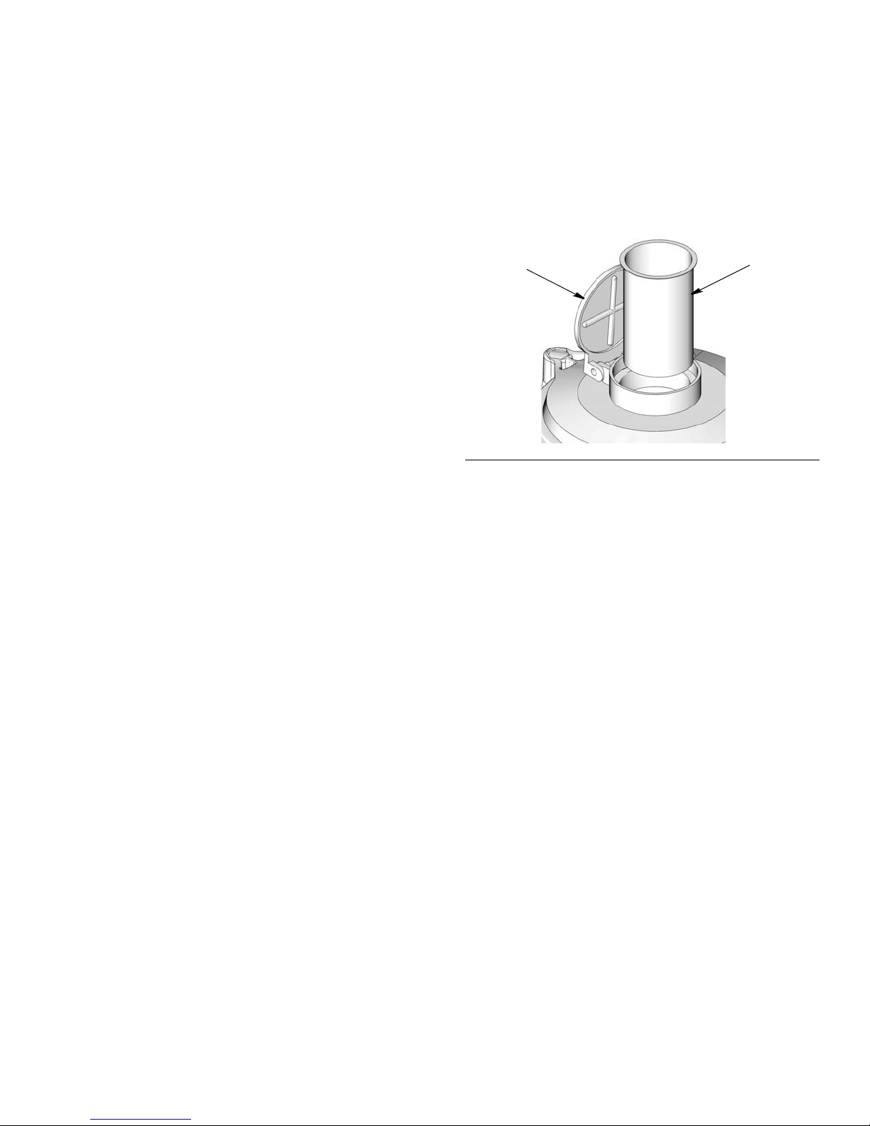
Setup
31
30
Setup
Filling the Reservoir
Material Cleanliness
Make sure that lubricant used to fill the system is clean.
If there is doubt about cleanliness, lubricant should be
filtered before being introduced into the system. System
life and consistent operation will both be improved by
using clean lubricant.
After filtering the lubricant, make sure the lubricant supply is protected from debris.
On all pumps, the lube piston diameter is very close to
the diameter of the chamber in the pump body. Contaminants in the lubricant could cause scoring in this area,
resulting in erratic pump operation and costly parts
replacement.
Temperature Effects
Flow characteristics of the lubricant may change if the
area the unit is used in goes through drastic temperature changes. Choose a lubricant that will flow properly
at all temperatures expected in the system environment.
Overhead Supply Adapter Assemblies Only
Filling Oil Reservoirs
Oil reservoirs have a fill cap (30) and filter (31).
FIG. 4
1. Wipe the area around the fill cup to avoid contamination during filling.
2. Open the fill cap (30) and slowly pour oil into the
reservoir (11) through the filter screen (31).
NOTE: The filter screen (31) will remove large particles which may be present in the oil.
The recommended inlet pressure is 15 psi (0.103 MPa,
1.03 bar) or less.
3. When filling is complete, close fill cap (30) and wipe
any spillage.
3A2781A 9
Page 10
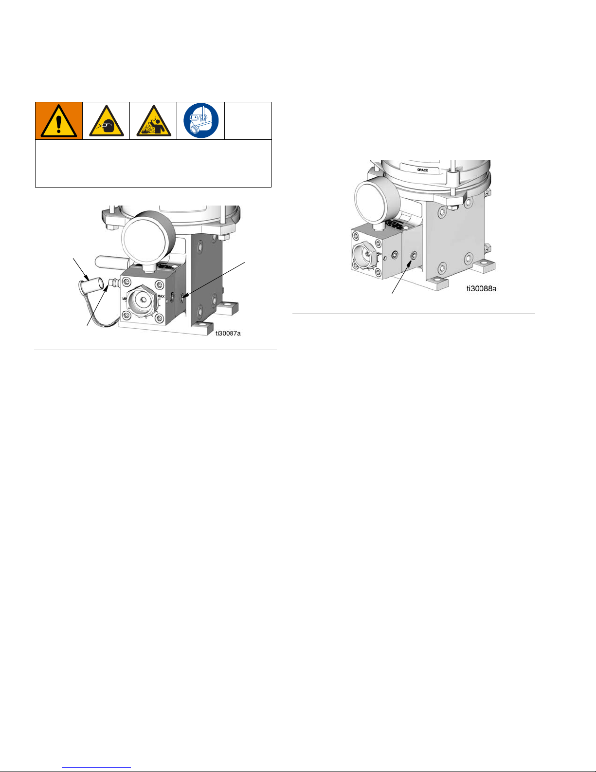
Setup
12
E
13
E
Filling Grease Reservoirs
OVER PRESSURIZATION HAZARD
Over pressurization can result in equipment rupture
and serious injury. Fill slowly to avoid over pressurizing the reservoir.
FIG. 5
• Filling grease reservoirs requires an external,
air-free supply source be connected to the fill stud
(13).
• To avoid introducing air into the system, make sure
there is enough grease in the supply source to fill
the reservoir without being disconnected.
• Operate the supply source at a steady speed to
allow air-free filling of the reservoir. Filling the reservoir too fast may result in air pockets.
1. Remove cover (12)
2. Connect grease supply source to fill stud (13).
3. Loosen the drain plug (E) (located on the opposite
side of the base from the fill stud (13) (F
IG. 6).
FIG. 6
4. Slowly begin to fill the reservoir, allowing air trapped
under follower to exhaust out the open drain plug.
5. When grease free of air flows from the drain, tighten
the plug (E) and continue to fill the reservoir until follower is at the vent hole in reservoir tube (any
remaining air and small amount of grease will exit
drain).
6. When filling is complete, turn off the supply source
and disconnect if from the fill stud (13). Replace the
cover (12).
NOTE: A check valve in the fill stud will prevent
lubricant from being forced back out.
• The level of grease is checked by visual means.
- In reservoirs with plastic cylinders, the grease level
can be viewed through the cylinder.
10 3A2781A
7. Loosen system mainline connection at pump outlet.
8. Operate pump until lubricant free of air flows from
outlet port.
9. Tighten mainline connection at pump. Pump is now
free of air.
NOTE: If the pump will not take a prime, it may be
helpful to inject several ounces of heavy oil through
the fill stud. The pump will then prime on oil pulling
the grease behind it. If it becomes necessary to use
this method, all injected oil should be discharged at
the loosened system mainline connection along with
any air.
Page 11
Setup
System Filling
After the reservoir is filled as described in Filling the
Reservoir, page 9, fill the remainder of the system by
attaching a hand pump to the system downstream from
the pump manifold block assembly and cycle the hand
pump until the system is filled.
Manifold Bleeding
Proper filling of the system will reduce the chance of air
entrapment. The pump block manifold assembly (117,
page 28) must be bled to remove air which will be
trapped inside the pump. Cycle the pump several times
until air-free lubricant is dispensed.
NOTE: Manual air bleeding procedures are necessary
in the event any system components are loosened, disconnected or otherwise removed after their initial installation.
Adjusting the Clutch Drive
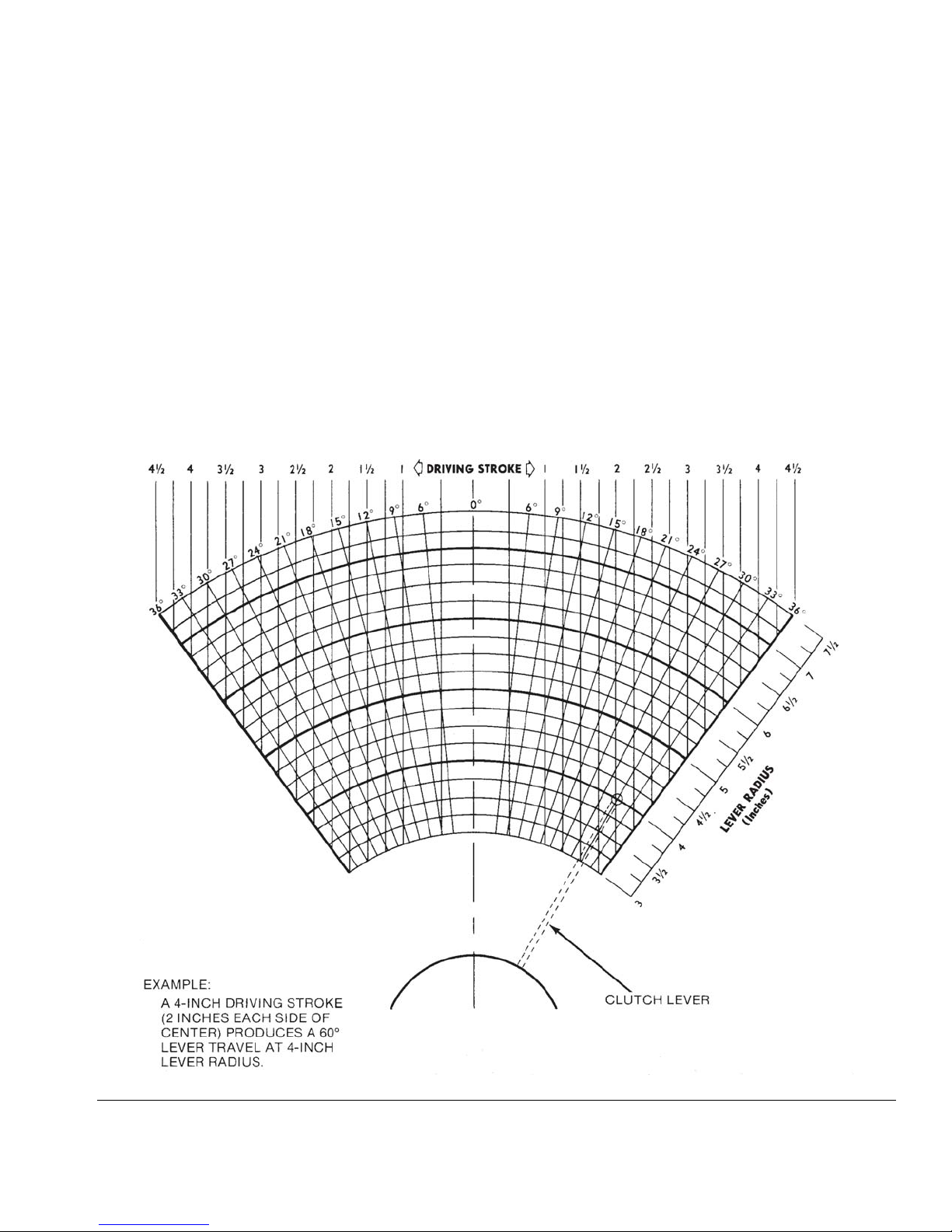
The degrees of throw of the clutch lever is adjustable
from 12 to 60 degrees. Table 1 (page 12) provides the
minimum/maximum pump outputs. The actual pump
output for your installation may be computed by using
the Calculating Pump Output procedure (page 12).
Using the clutch lever diagram provided in F
mine the anticipated clutch lever throw angle.
IG. 7 deter-
FIG. 7
3A2781A 11
Page 12
Setup
Clutch Drive - Calculating Pump Output
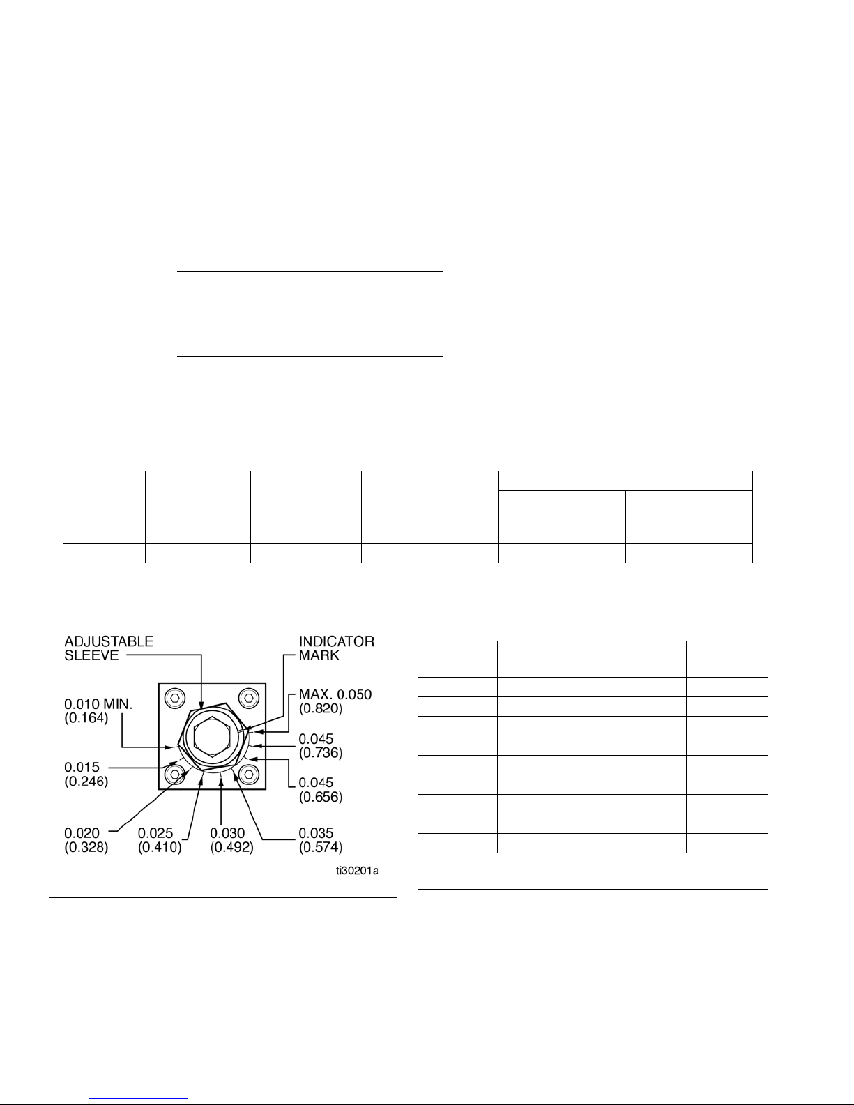
The standard pump output can be varied, from 0.010 to 0.050 cubic inches (0.1639 to 0.8195 cu. cm) per cycle, by
changing the position of the pump adjustment sleeve (2) (F
high volume pump has a fixed output.
To calculate the pump output per hour, use the following formulas:
IG. 1, page 6) located below the pressure gauge (3). The
360°
Degrees of Throw
* Degrees of Throw can be found by using clutch lever diagram (F
IMPULSES/HOUR
RATIO
Pump strokes per hour x 0.010 = Minimum Pump Output per Hour
Pump strokes per hour x 0.050 = Maximum Pump Output per Hour
= Effective Ratio
IG. 7, page 11)
PUMP STROKE PER HOUR
=
Table 1: Minimum / Maximum Pump Output
Degrees of
Throw
Effective Ratio Impulses Per
Minute
Output Per Hour
Pump Strokes Per
Cubic Inches (Cubic Centimeters)/hour
Minimum Maximum
Hour
12 30:1 5 Minimum 10 0.100 (1.639) 0.500 (8.195)
60 6:1 150 Maximum 1500 15.00 (245.8) 75.00 (1229)
Standard Pump Adjustment
Table 2: Standard Output/Stroke Adjustment
Percent of
Output
100 0.050 (0.820) Max.
90 0.045 (0.737) *1st
80 0.040 (0.656) *2nd
70 0.035 (0.574) *3rd
60 0.030 (0.492) *4th
50 0.025 (0.410) *5th
40 0.020 (0.328) *6th
30 0.015 (0.246) *7th
20 0.010 (0.164) Min.
* All marks are counting clockwise from the maximum
setting.
FIG. 8
Output Per Stroke Cubic
Inches (Cubic Centimeters)
Adjustment
Mark
12 3A2781A
Page 13
Operation
a
Operation
Startup
Before attempting to operate any system, check the
following:
• Ensure the reservoir is securely fastened to the
pump and that the fill cap or grease-fill fitting is easily reached.
• Check that the pump is securely fastened in place.
• Check that gear reducer has been filled with proper
lubricant.
• Check all electrical connections to any controllers,
level switches or pressure switches used on the system.
While the system is operating, periodically check
the following components:
• Check that the pump is cycling according to schedule.
• Visually check the unit for leaks and loose fittings.
Make sure that hoses do not become kinked and
are not rubbing on anything.
• If the reservoir is not equipped with a low-level
switch, visually check the lubricant level and refill
before all lubricant is used.
NOTE: If the reservoir is allowed to run dry, excess
air will be introduced into the system, requiring that
the system be bled.
Pressure Relief Procedure
Follow the Pressure Relief Procedure whenever
you see this symbol.
• Check that all accessories plumbed into the output
manifold block assembly are secure.
• Make sure all hose or tubing connections are tight.
• Check that the reservoir is filled with lubricant. See
Filling the Reservoir, page 9.
• Check that all filling and bleeding steps have been
completed.
• Check the output of the lubricant pump. Adjust the
output as described in the Clutch Drive - Calculating
Pump Output, page 12.
• If the pump is equipped with a clutch drive, verify it
is properly adjusted as described in the Adjusting
the Clutch Drive section, page 11.
The unit is now ready to run. The pump is cycled by an
external source, such as a timer, counter, control package, or customer-supplied drive. Once this external
source is engaged, the unit will cycle as programmed.
This equipment stays pressurized until pressure is
manually relieved. To help prevent serious injury from
pressurized fluid, such as skin injection, splashing
fluid and moving parts, follow the Pressure Relief Procedure when you stop dispensing and before cleaning, checking, or servicing the equipment.
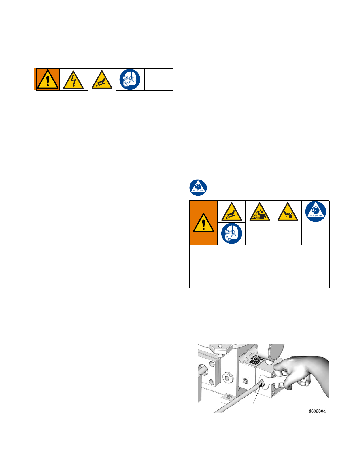
1. Verify pump is stopped and disconnected from
power source.
2. Using a wrench, slowly loosen the outlet fitting (a,
F
IG. 9) connected to the pump block manifold
assembly until the fitting is loose and no more lubricant or air is leaking from the fitting.
3A2781A 13
FIG. 9
Page 14
Troubleshooting
Troubleshooting
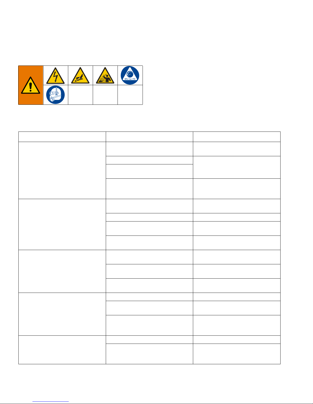
Many system problems may be caused by loose connections or trapped air in the system. Before removing system
components, check all connections to make sure they are tight. Also make sure the system is properly bled.
Problem Cause Solution
No lubrication is dispensed from
pump, but pump is rotating
Pump is Not Running or Requires
Service
No lubrication is dispensed from
pump and drive shaft is not rotating
Motor is Not Running
No Gear Reducer Output
Reservoir is empty
Check valve is defective
Adjustment sleeve seals are defective
Problem is in the pump
Yoke connector pin and piston are
defective
Sheared drive motor key Replace key.
Broken pump drive shaft
Piston is not engaged in sleeve
Motor is not running
No gear reducer output
Defective pump input shaft
Power is off Turn power on.
Electric connections to motor or timer
are loose
Timer/controller is set incorrectly or
defective
Key is sheared or missing at coupling Replace key.
Defective gearbox
Refill as required. See Filling The
Reservoir, page 9.
Clean and install seal repair kit.
See Pump is Not Running or
Requires Servicing section of this
Troubleshooting Table.
Replace defective parts using Pump
Drive Repair Kit.
Replace defective parts using Pump
Drive Repair Kit.
Replace defective parts using Output Manifold Kit.
Refer to Motor is Not Running section
of this Troubleshooting Table.
Refer to No Gear Reducer Output
section of this Troubleshooting Table.
Replace defective parts using Pump
Drive Repair Kit.
Check all connections and tighten
securely.
Set timer/controller to correct setting.
If unit is still not functioning, repair or
replace timer/controller.
Gearbox must be replaced. For this
repair unit must be returned to an
authorized Graco repair facility.
14 3A2781A
Page 15
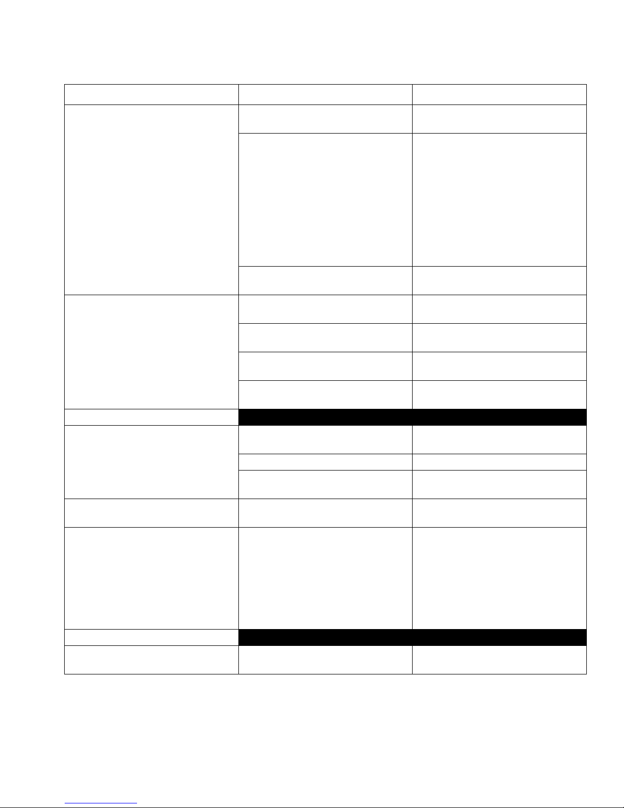
Problem Cause Solution
Troubleshooting
Clutch drive is operating but there is
no flow
Erratic pump output
Grease Models
Lubricant is leaking from the reservoir
Restricted movement of follower
plate
Pump will not take a prime
Oil Models
Oil reservoir is filling very slowly
Reservoir is empty
Refill as required. See Filling The
Reservoir, page 9.
Remove clutch and operate pump
manually.
• If there is output, replace clutch.
For this repair unit must be
Clutch is defective
returned to an authorized Graco
repair facility.
• If there is no output, see Pump is
Not Running or Requires Servicing section of this Troubleshooting Table.
Fluid temperature is below 12°F
(-11°C)
System was not bled properly
Pump seals, check valves or o-rings
are defective
Pump adjustment assembly is leaking or sucking air during return stroke
Piston or bore is worn
Hex nuts (1) are not tight
Do not attempt to operate until temperature problem is corrected.
Bleed manifold. See Manifold Bleeding, page 11.
Replace defective parts using Pump
Drive Repair Kit.
Tighten output manifold block assembly components.
Replace defective parts using Output Manifold Kit.
Tighten hex nuts (1). Torque to 5 ft.
lbs (6.78 N•m).
Damaged or worn gasket (8) Replace gasket (8).
Cracks or nicks in reservoir tube (11)
or reservoir is dented or out-of-round
Dented or out-of-round reservoir tube
(11)
Replace reservoir tube (11).
Replace reservoir tube (11).
Inject several ounces of heavy oil
through the grease fill quick discon-
nect. The pump will then prime on oil,
Grease will not pull into pump
through quick disconnect
pulling the grease behind it. If it
becomes necessary to use this
method, all injected oil should be dis-
charged at the loosened system sup-
ply connection along with any air.
Fill screen (31) located in fill cap (30)
is clogged
Clean or replace fill screen (31).
3A2781A 15
Page 16
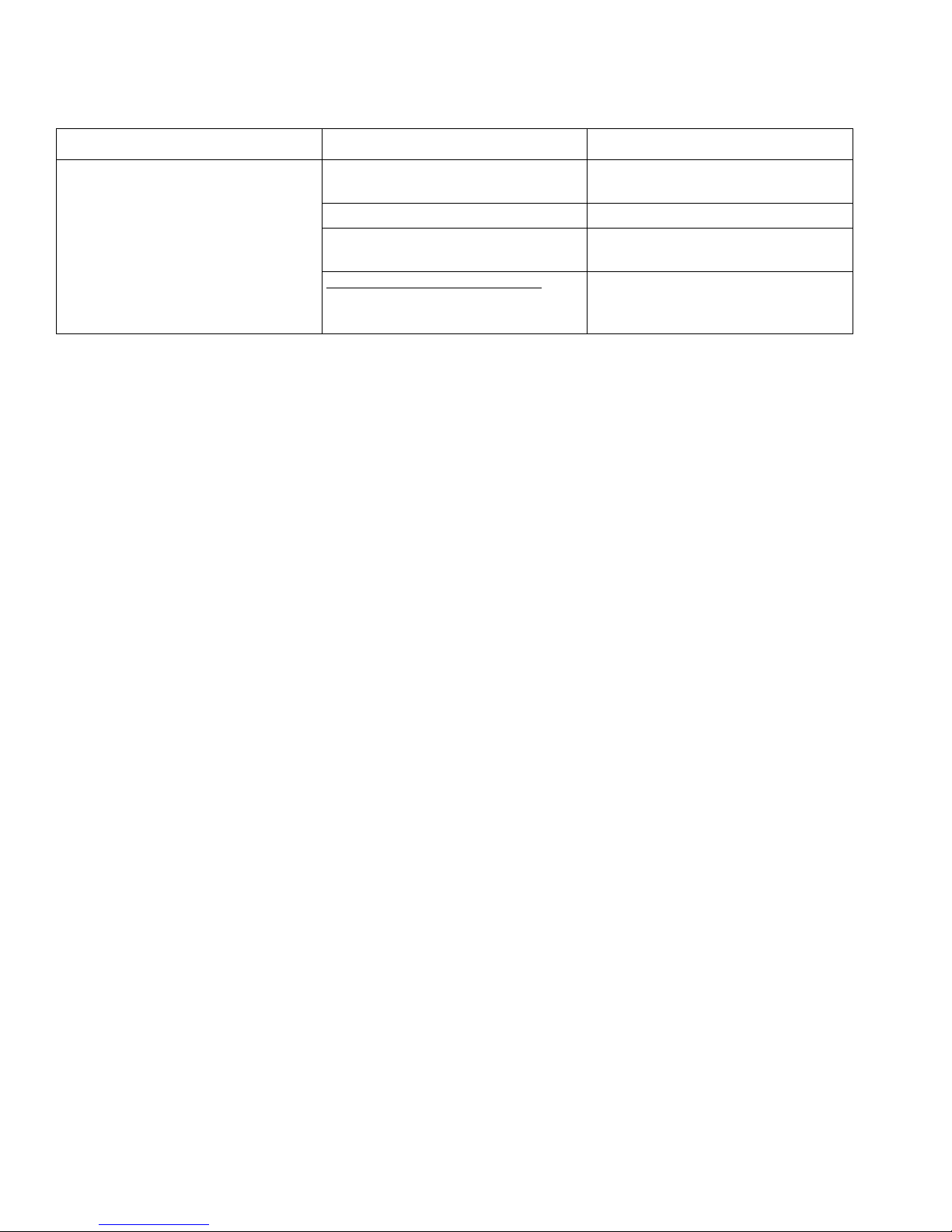
Troubleshooting
Problem Cause Solution
Lubricant is leaking from the reservoir
Hex nuts (1) are not tight
Tighten hex nuts (1). Torque to 5 ft.
lbs (6.78 N•m)
Damaged or worn gasket (8) Replace gasket (8)
Cracks or nicks in reservoir tube (11)
or reservoir is dented or out-of-round
Overhead supply adapter only:
Exceeded recommended inlet pressure of 15 psi (0.103 MPa, 1.03 bar)
Replace reservoir tube (11)
Decrease pressure to 15 psi (0.103
MPa, 1.03 bar) or less
16 3A2781A
Page 17
Maintenance and Repair
101
116
104
Maintenance and Repair
Pumps: Oil and Grease Models
AUTOMATIC SYSTEM ACTIVATION HAZARD
The system is equipped with an automatic timer that
activates the pump lubrication system. Unexpected
activation of the system could occur and result in
serious injury, including skin injection and amputation.
Before you install or remove the lubrication pump
from the system, disconnect and isolate all power
supplies and relieve all pressure.
Preparing for Maintenance
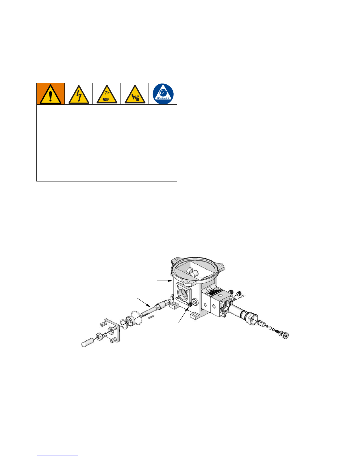
Refer to FIG. 10 for reference numbers used in the following instructions.
Before proceeding with any maintenance, the following
procedure must be completed:
1. Disconnect all electrical power and air supplies to
the pump.
2. Relieve pressure, page 13.
3. For pumps with oil reservoirs, remove pipe plug
(116, F
container.
Omit Step 3 for pumps with grease reservoirs. Install
plug (116) after draining is complete.
4. Remove the reservoir.
5. Remove pump body assembly from its mounting as
follows:
a. Remove all guards and mechanical linkages or
b. Remove all attaching hardware securing pump
c. Remove all grease or oil from the pump body
IG. 10) and drain oil into a suitable, clean
connections at the pump drive shaft (104).
body (101) in place.
(101).
FIG. 10
3A2781A 17
Page 18
Maintenance and Repair
9
3
11
4
23
25
10
19
15
6
17
8
5
1
13
12
Grease Reservoirs
Disassembly
The disassembly procedure may be performed with the
reservoir mounted on the pump. However, some mounting locations are too restrictive to provide access to all
components.
If installation requires dismounting of the reservoir, drain
the reservoir of lubricant before removing the attaching
hardware. This will reduce the weight of the reservoir
and reduce the chance of spillage.
FLYING PARTS HAZARD
The expansion spring (10) is always under great tension and could be propelled with enough force to
cause serious injury. Never remove retaining ring (4)
or cable assembly (19).
.
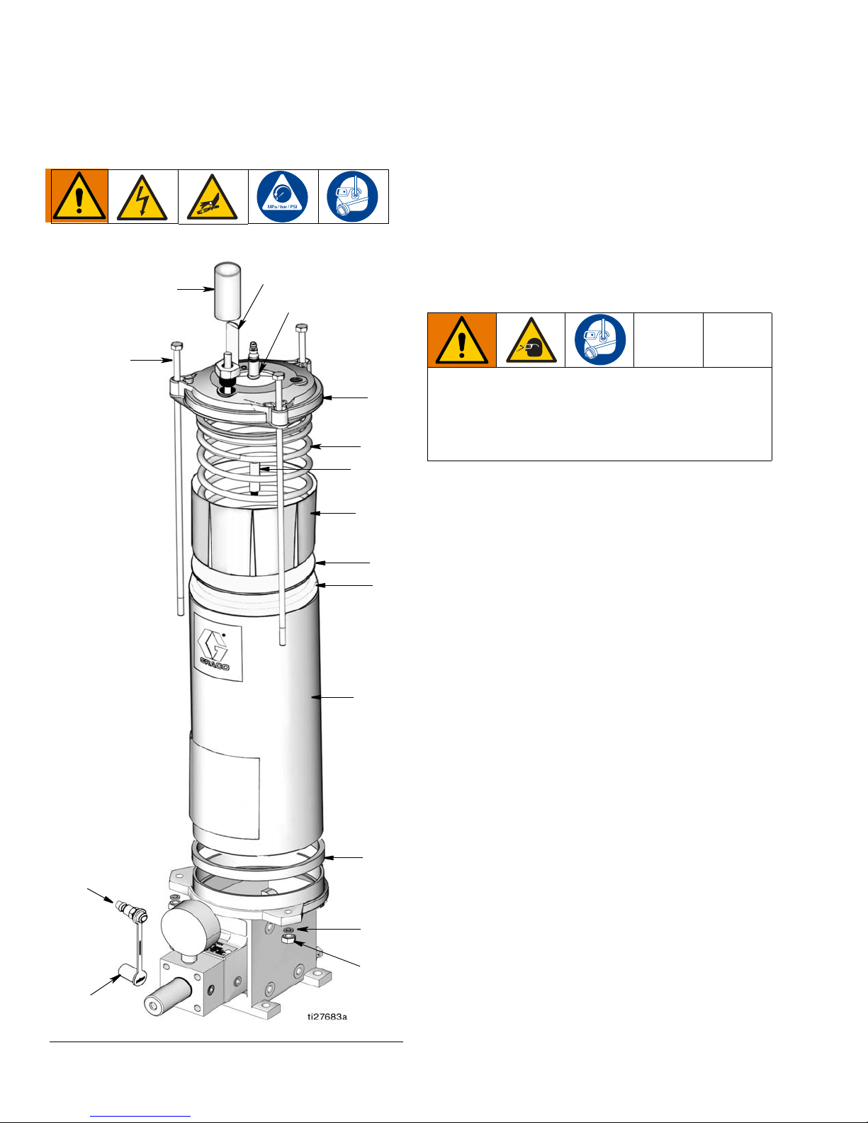
1. Slowly open reservoir drain (E, FIG. 1, page 6) and
allow lubricant to be forced from the reservoir into a
bucket or similar container.
All lubricant must be drained before removing the
attaching hardware to reduce the weight of the reservoir
and reduce the chance of spillage.
2. Properly dispose of emptied grease adhering to all
applicable safety regulations and municipality
codes.
3. Remove fill stud (13) if necessary.
4. Remove hex nuts (1) and lockwashers (5) from tie
rods (3).
5. Remove tie rods (3) from reservoir cap (9).
6. Lift reservoir (11) from pump keeping reservoir cap
(9) in position on top of the tube.
7. Slide reservoir (11) away from reservoir cap (9) until
it is free of follower cups (15 and 17).
8. Remove gasket (8) from pump.
NOTE: Further disassembly is only possible at the
factory. If damage is apparent on the follower cups
(15 and 17), cable assembly (19), spring (10) or reservoir cap (9) the unit cannot be serviced and the
reservoir assembly must be replaced.
FIG. 11
18 3A2781A
Page 19
Maintenance and Repair
304
a
b
d
c
A
B
C
Assembly
Before assembling, lubricate followers and tube inner
diameter with the same lubricant used in the system.
1. Slide reservoir (11) over follower cups (15 and 17)
being careful not to distort the follower cup lips.
Slide reservoir tube up until it contacts reservoir cap
(9).
2. Install new gasket (8) on pump.
3. Place reservoir (11) on gasket (8) and rotate reservoir cap (9) until holes in the cap line up with holes
in the pump.
4. Install tie rods (3) through holes in reservoir cap (9)
and pump.
5. Install lockwashers (5) and hex nuts (1) on tie rods
(3) and torque to 5 ft-lbs (6.78 N•m).
6. Install fill stud (13) and dust cap (12) in pump.
When the assembly is completed, any components
which were removed to ease disassembly should be
reinstalled on the reservoir.
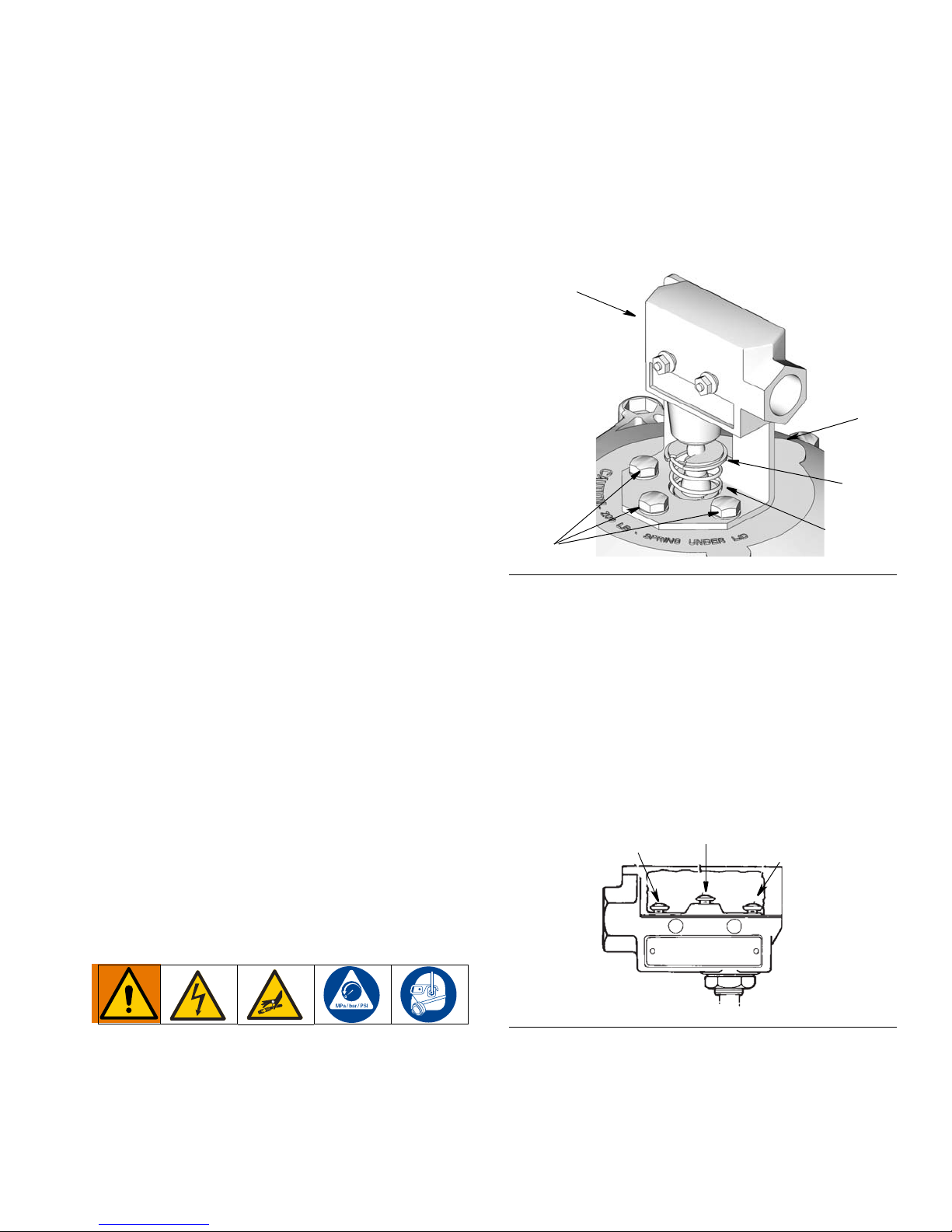
2. Disconnect and remove all wiring from the low level
switch (304).
3. Remove low level switch (304) from bracket (a).
4. Remove retainer ring (b) and spring (c).
5. Remove three screws (d) and bracket (a).
FIG. 12
Low-Level Switch Assemblies
Refer to FIG. 12 for reference numbers used in the following instructions.
If the grease level runs down and the switch assembly
fails to perform as required:
• check all electrical connections to make sure they
are secure
• check for any physical obstructions which might be
preventing the switch from operating. If an obstruction is found, disassemble the unit and clear the
obstruction.
If switch assembly is damaged, replace the switch
assembly using the following procedure.
Disassembly
Assembly
1. Attach bracket (a) to grease reservoir cover using
three self-tapping screws (d) (F
2. Place spring (c) (F
IG. 12) over tip of level indicator.
IG. 12).
3. Compress spring (c) and place retainer ring (b)
between spring and tip of level indicator (F
4. Attach low level switch (5) to bracket (a) (F
IG. 12).
IG. 12).
5. Wire low level switch (304a) in accordance with local
electrical codes. Refer to wiring diagram (F
IG. 13).
FIG. 13: Low Level Switch Wiring
1. Disconnect all electrical power, air supplies and
relieve pressure to the lube system. (See Pressure
Relief Procedure on page 13)
3A2781A 19
A Normally closed
B Normally open
C Common
Page 20
Maintenance and Repair
31
30
3
11
9
8
5
1
Oil Reservoirs
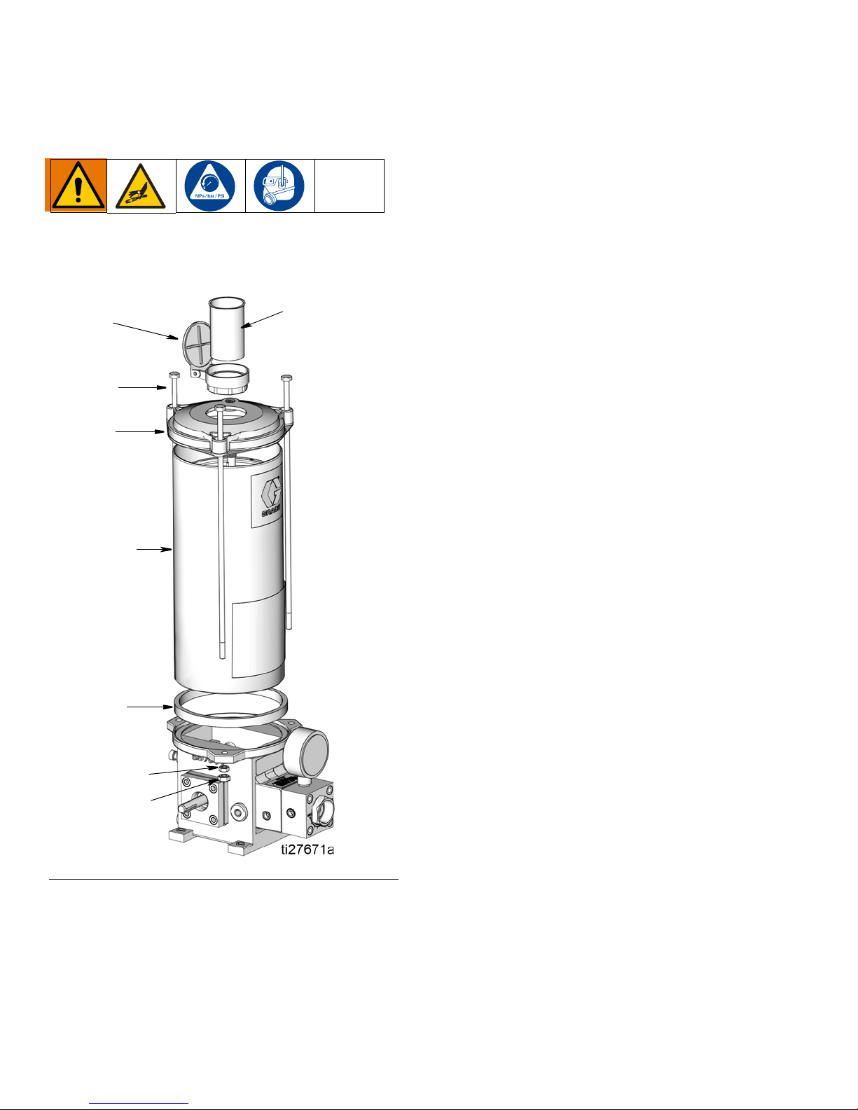
Refer to FIG. 14 for reference numbers used in the
following instructions.
Disassembly
The disassembly procedure may be performed with the
reservoir mounted on the pump. However, some mounting locations may be too restrictive to provide access to
all components.
If installation requires dismounting of the reservoir,
make sure the reservoir is drained of lubricant before
removing the attaching hardware. This will reduce the
weight of the reservoir and reduce the chance of spillage.
1. Drain oil (see Preparing for Maintenance on page
17). Allow oil to drain into bucket or similar container
and properly dispose of emptied oil.
2. Remove three hex nuts (1) and lock washers (5)
from tie rods (3).
3. Remove tie rods (3) from reservoir cover (9).
4. Remove reservoir cover (9) from reservoir (11).
5. Remove fill screen (30) from fill cap (31) and clean
screen.
6. Remove reservoir (11) from pump.
FIG. 14
7. Remove and discard gasket (8) from pump.
Assembly
1. Install fill screen (30) in fill cap (31).
2. Install new gasket (8) in pump.
3. Position reservoir (11) on pump and position reservoir cover (9) on tube.
4. Align holes in reservoir cover (9) and holes in pump.
Install tie rods (3) through holes in cover and pump.
The heads of tie rods (3) must fit into the hexagonal
depressions on the upper surface of the reservoir
cover (9).
5. Install lock washers (5) and hex nuts (1) on tie rods
(3).
6. Torque nuts to 5 ft-lbs (6.78 N.m).
NOTE: When the assembly is completed any components which were removed to ease disassembly
should be reinstalled on the reservoir.
20 3A2781A
Page 21
Maintenance and Repair
304
304a
9
304b
304e
304c
304f
C
B
A
15 Amp Low-Level Switch Assembly Option
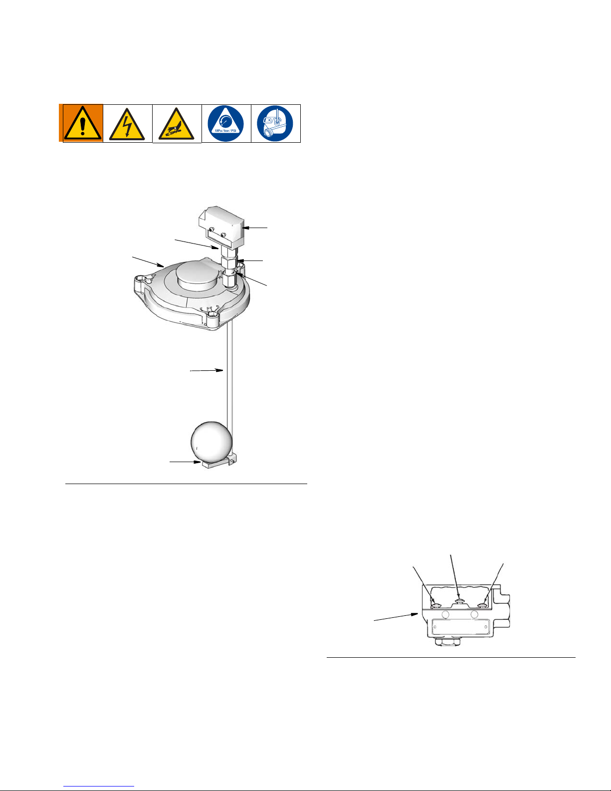
Refer to FIG. 15 for reference numbers used in the following instructions.
6. Unscrew low-level lower assembly (304e) from
low-level adapter (304b).
7. Unscrew low-level adapter (304b) from reservoir
cover.
8. Remove low-level adapter (304b) from union nut
(304c).
Assembly
The following procedure is used for installing a new
assembly in a reservoir. If your assembly was removed
for repairs, Steps 1 and 2 do not apply.
1. Remove cover (9) from reservoir (11).
2. Remove 1/4 inch plug (7) from reservoir cover (9).
3. Insert low-level adapter (304b) into union nut (304c).
4. Screw low-level adapter (304b) into the reservoir
cover (9) and tighten securely.
5. Screw low-level lower assembly (304e) into
low-level adapter (304b) and tighten securely.
If float portion of low-level lower assembly was removed
during disassembly, apply Loctite
®
to the attaching bolt
and securely attach the float to the arm.
FIG. 15
If the oil level runs low and the assembly fails to perform
as required, the unit may have to be disassembled to
replace a defective switch assembly.
Before disassembling, check all electrical connections to
make sure they are secure and check for any physical
obstruction which might be preventing the float from
operating.
Disassembly
1. Disconnect all electrical power and all air supplies to
the lube system.
2. Remove cover (9) from reservoir (11).
3. Unscrew union nut (304c) from switch adapter
(304a).
4. Unscrew switch adapter (304a) from switch (304).
5. Remove actuating rod, part of low-level lower
assembly (304f), from remaining assembly.
6. Insert the actuating rod, part of low-level lower
assembly (304e), into this assembly.
7. Screw switch adapter (304a) into switch (304) and
tighten securely.
8. Screw union nut (304c) onto switch adapter (304a)
and tighten securely.
9. Install cover (9) on reservoir (11).
10. Wire switch (304) in accordance with local electrical
codes. Refer to wiring diagram (F
IG. 16).
FIG. 16
A Normally closed
B Normally open
C Common
3A2781A 21
Page 22
Maintenance and Repair
304k
304m
304n
304p
9
10-Watt Low-Level Assembly Options
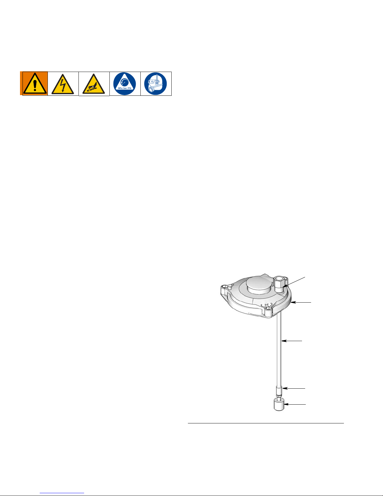
Refer to FIG. 17 for reference numbers used in the following instructions.
No maintenance is required on the 10 watt low-level
assemblies used on oil reservoirs.
If the oil level runs low and the assembly fails to perform
as required the unit may have to be disassembled to
replace a defective and switch. Before disassembling,
check all electrical connections to make sure they are
secure and check for any physical obstructions preventing the float from operating.
Disassembly
1. Relieve pressure and disconnect all electrical power
and air supplies to the lube system.
2. Disconnect two 22 AWG wires from the top of the
adapter (304k).
3. Disconnect adapter (304k) from the conduit.
Assembly
The following procedure is used for installing a new
assembly in a reservoir. If your assembly was removed
for repairs, steps 1 and 2 do not apply.
1. Remove the cover (9) from the reservoir (11).
2. Remove the 1/4 inch pipe plug from the cover.
Screw adapter (304k) in and tighten it securely.
3. Guide two 22 AWG wires from switch (304p)
through coupling (304n).
4. Screw coupling (304n) onto switch (304p) and
tighten securely.
5. Guide two 22 AWG wires through coupler (304m).
6. Screw coupler (304m) into coupling (304n).
7. Guide two 22 AWG wires through adapter (304h).
8. Screw coupler (304m) into adapter (304k). Use caution to not to twist the wires too much.
9. Tighten the connection.
10. Connect switch (304p) in accordance with local
electrical codes.
4. Remove the cover (9) from the reservoir (11).
5. Unscrew coupler (304m) from adapter (304k). Use
caution to not twist the wires too much.
6. Unscrew coupler (1304m) from coupling (304n).
7. Unscrew coupling (304n) from switch (304p).
8. Unscrew adapter (304k) from the reservoir cover
(9).
FIG. 17
22 3A2781A
Page 23
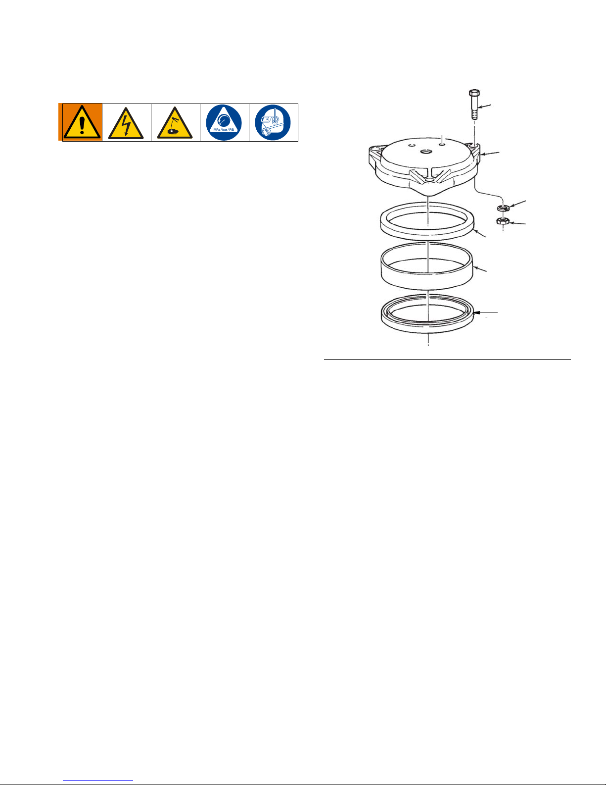
Overhead Supply Adapter
203
209
204
201
205
210
206
Refer to FIG. 18 for reference numbers used in the following instructions.
Disassembly
The disassembly procedure may be performed with the
adapter mounted on the pump. However, some mounting locations may be too restrictive to provide access to
all components.
If installation requires dismounting of the adapter, make
sure the adapter is drained of lubricant before removing
the attaching hardware. This will reduce the weight of
the adapter and reduce the chance of spillage.
Maintenance and Repair
1. Shut off the lubricant supply to the overhead supply
adapter and drain oil from reservoir. See Preparing
for Maintenance on page 17 for reservoir draining
instructions. Properly dispose of emptied oil
adhering to all applicable safety regulations and
municipality codes.
2. Remove three nuts (201) and lock washers (204)
from screws (203).
3. Remove screws from reservoir cap (209).
4. Remove reservoir cover (209) from adapter tube
(210).
5. Remove adapter tube (210) from pump.
6. Remove and discard gaskets (205 and 206).
FIG. 18
Assembly
1. Install lower gasket (206) on pump body.
2. Install adapter tube (210) on gasket (206).
3. Install reservoir gasket (205) on top of adapter tube
(210).
4. Install reservoir cap (209) on reservoir gasket (205).
5. Rotate reservoir cover (209) until screws (203) can
be installed through holes in cap and pump. Heads
of screws (203) must fit into the hexagonal depressions on the upper surface of the reservoir cover
(209).
6. Install lock washers (204) and nuts (201) on screws
(203).
7. Torque nuts to 5 ft-lbs (6.78 N•m).
When the assembly is completed any components
which were removed to ease disassembly should be
reinstalled on the adapter.
3A2781A 23
Pump Drive Repair Kit 563915
See instructions included with repair kit for procedure.
Page 24

Maintenance and Repair
Output Manifold Repair Kit 563916
See instructions included with repair kit for procedure.
Seal Repair Kit 563921
See instructions included with repair kit for procedure.
Installation After Maintenance
After pump maintenance has been accomplished, perform the following procedure to return the unit to service.
1. Locate the pump body and assembled parts at the
position from which it was removed and secure with
attaching hardware. Make certain all fasteners are
tightened to the proper torque.
2. Install all guards and mechanical linkages or connections removed at the pump drive shaft.
3. Install the reservoir.
4. Electrically reconnect the pump drive.
5. Replace drain plug (116).
Recommended Lubricants for
Enclosed Gear Reducers
AMBIENT
(Room)
TEMP
-30° to 225° F**
(-34° to 107°C)
40° to 90° F
(4.4° to 32.2°C)
80° to 125° F
(26.7° to
51.7°C)
RECOMMENDED
OIL (or equivalent)
MOBIL SHC 634*
SYNTHETIC
MOBIL 600W
CYLINDER OIL
MOBIL EXTRA
HECLA SUPER
CYLINDER OIL
VISCOSITY
RANGE SUS
@ 100° F
(38°C)
1950/2150 --- 320/460
1920/3200 7 or 7C 460
2850/3600 8 or 8C 680
LUBRICANT
AGMA N O.
The gear reducer requires 7.8 ounces (230.7 ml) of
clean lubricant as listed above.
The lubricant must remain free from oxidation and contamination by water or debris, since only a very thin film
of oil stands between efficient operation and failure. To
assure long service life, the reducer should be periodically drained (preferably while warm) and refilled to the
proper level with a recommended gear oil. Under normal
environmental conditions oil changes are suggested
after the Alternative AGMA Lubricants initial 250 hours
of operation and thereafter at regular intervals of 2500
hours or every 6 months.
ISO
VISCOSITY
GRADE NO.
+
Drive and Motor
There is little maintenance required on the clutch drive.
The clutch drive assembly replacement part number
563383 is available from Graco. Contact your local
Graco distributor for assistance in ordering this part.
Synthetic lubricants will allow extended lubrication intervals due to its increased resistance to thermal and oxidation degradation. It is suggested that the initial oil
change be made at 1,500 hours and, thereafter, at
5,000 hour intervals.
Alternative AGMA Lubricants
MANUFACTURER LUBRICANT NAME AGMA RATING
Getty Refining Co.
Getty Refining Co.
Getty Refining Co.
Lubrication Engr.
Inc.
Lubrication Engr.
Inc.
Mobil Oil Corp.
Mobil Oil Corp.
Mobil Oil Corp.
Shell Oil Co.
Shell Oil Co.
Shell Oil Co.
Texaco Inc.
Texaco Inc.
Veedol Asreslube 98
Veedol Asreslube 95
Veedol Asreslube 90
Almasol 609
Almasol 608
Mobilgear 634
Mobil Extra Hecia Super
Mobil Cylinder 600W
Omala 460
Valvala J460
Omala 680
Valvala J680
Meropa 680
Meropa 460
8 EP
7 EP
6 EP
8
7
8 EP
8
7
7 EP
7
8 EP
8
8 EP
7 EP
24 3A2781A
Page 25
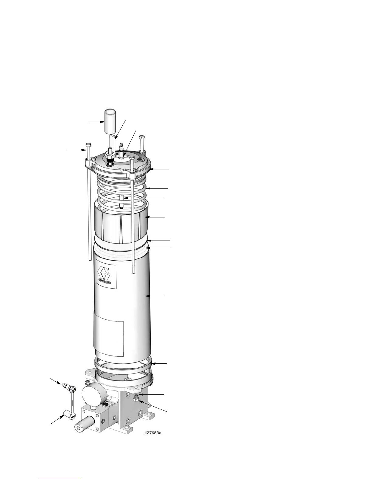
Parts
9
3
11
4
23
25
10
19
15
6
17
8
5
1
13
12
Parts
Grease Reservoirs: 562896,
562897, 562898, 562899
Ref Part No. Description Qty.
1 NUT, 5/16-18 hex 3
2 NUT, elastic lock 5/16-18 hex (not
shown)
3# ROD, tie, reservoir 3
4 RING, retainer, 1/2 ID 1
5# WASHER, lock 3
6 WASHER, reservoir (models 562896,
562897 only)
8 GASKET, reservoir 1
9 COVER, reservoir 1
10 SPRING, follower 1
11 RESERVOIR 1
12 557373 CAP, dust fill stud 1
13 557374 STUD, fill stud assy 1/4 NPT 1
14 PLATE, reservoir top (not shown) 1
15 CUP, follower 1
17 CUP, follower, reservoir 1
18 WASHER, spacer (models 562898,
562899 only)
19 CABLE, indicator 1
22 SCREW, drive (models 562898,
562899 only)
23 CAP, protective Moduflo (models
562898, 562899 only)
24 CLIP, indicator 12lb, 20 lb (models
562898, 562899 only)
25 563334 INDICATOR, level assy 5lb (model
562898 only)
563335 BODY, indicator assy 20 lb (model
562899 only)
1
1
1
1
1
1
1
1
3A2781A 25
Included in one of the following kits:
562902 KIT, reservoir replacement, 12 lb, plastic
(model 562896 only)
562903 KIT, reservoir replacement, 20 lb, plastic
(model 562897 only)
564270 KIT, reservoir replacement, 12 lb, metal
(model 562898 only)
564271 KIT, reservoir replacement, 12 lb, metal
(model 562899 only)
# Included in one of the following kits
258286 KIT, tie rod (models 562896, 562898 only)
258285 KIT, tie rod (models 562897, 562899 only)
Page 26
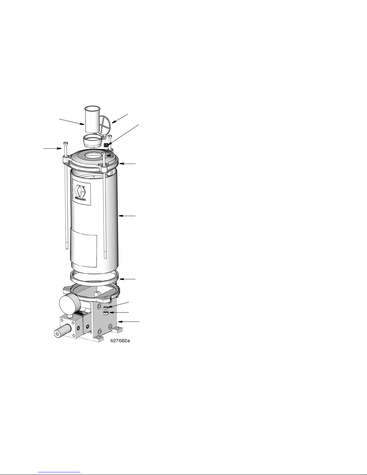
Parts
31
30
7
9
3
11
8
5
1
32
Parts
Oil Reservoirs: 562892, 562893,
562894, 562895
Ref.
Part No. Description Qty.
No.
1# NUT, 5/16-18 hex 3
3# ROD, tie, reservoir 3
5# WASHER, lock 3
7 PLUG, dryseal 1/4 nptf 2
8 GASKET, reservoir 1
9 COVER, reservoir 1
11 RESERVOIR 1
30 557797 CAP, fill, reservoir 1
31 557799 SCREEN, filter 1
32 563380 PUMP, assembly 1
Included in one of the following kits:
562902 KIT, reservoir replacement, 12 lb, plastic
(model 562892 only)
562903 KIT, reservoir replacement, 20 lb, plastic
(model 562893 only)
564270 KIT, reservoir replacement, 12 lb, metal
(model 562894 only)
564271 KIT, reservoir replacement, 12 lb, metal
(model 562895 only)
# Included in one of the following kits
258286 KIT, tie rod (models 562892, 562894 only)
258285 KIT, tie rod (models 562893, 562895 only)
26 3A2781A
Page 27
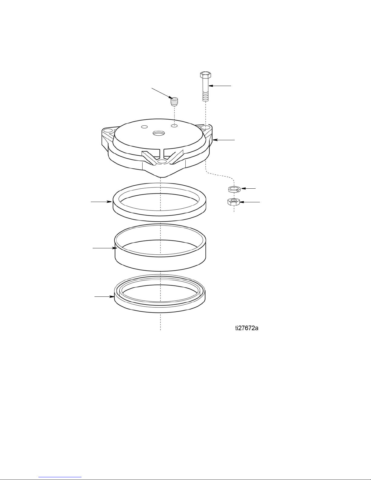
Overhead Supply Adapter Assembly 562908
207
203
209
204
201
205
210
206
Parts
Ref Part No. Description Qty.
201 NUT, 5/16 - 18 hex 3
202 PLUG, stl 1/2 pipe hex soc (not
shown)
203 SCREW, hex hd cap, 5/16 3
204 WASHER, lock 3
205 557333 GASKET, 6, 12, 20 lb reservoir 1
206 557334 GASKET, lower reservoir 1
207 PLUG, dryseal 1/4 nptf 1
209 CAP, resv 12 lb bolt 1
210 TUBE, adapter 1
1
3A2781A 27
Page 28
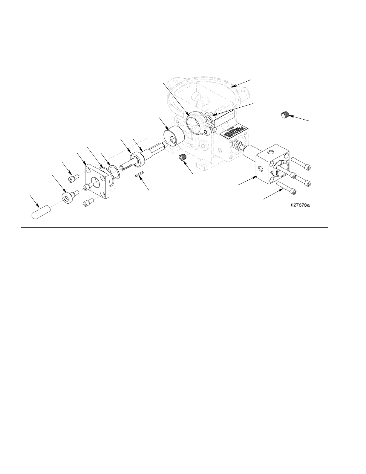
Parts
110
117
116
107
106
101
105
116
108
104
115
111
112
103
109
113
104
Pump Body Assembly: 563380
FIG. 19
Parts
Ref
No.
101 557644 BODY, pump 1
102 556361
103 PLATE, end 1
104 SHAFT, assembly 1
105 CAM 1
106 560773 YOKE 1
107 SPACER, 0.75 ID x 0.344 long 1
108 SPACER, 0.75 ID x 0.969 long 1
109 SCREW, SHCS 5/16 -18 x 0.50 4
110 SCREW, SOC head cap, 5/16 4
111 WASHER 1
112 O-RING 1
113 556576 SEAL, lip, 0.50 ID, 1.00 OD, 0.25 W 1
114 CAP, protective 1
115 KEY, square, 0.125 x 0.875 lg 1
116 557391 PLUG, dryseal, 1/4 NPTF 3
117 PUMP, block manifold assembly 1
Description Qty.
BEARING, ball, 0.50 ID x 1.37 OD
(not shown)
1
28 3A2781A
Page 29
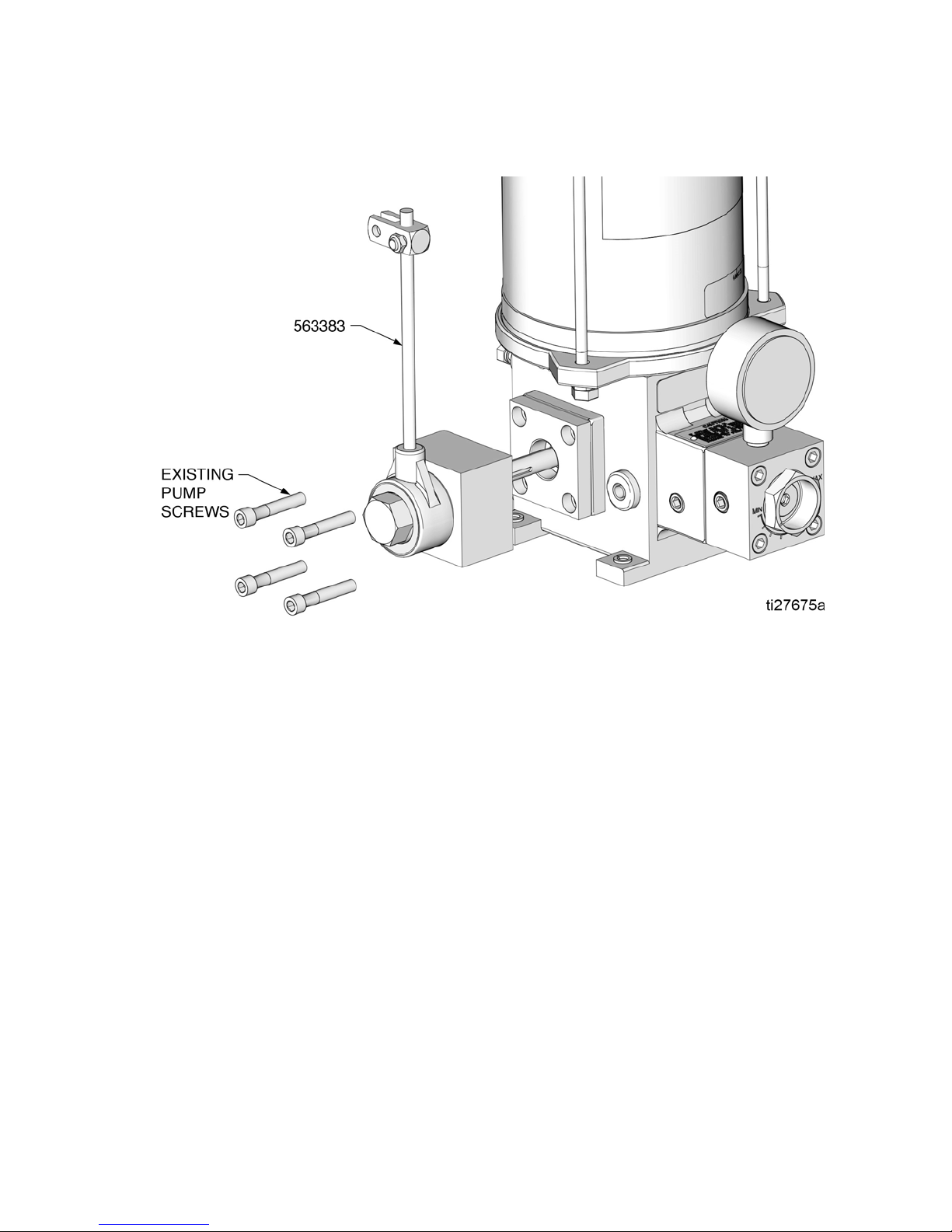
Clutch Drive Assembly: 563383
Parts
3A2781A 29
Page 30

Parts
LubeMaster Pump
Ref.
No.
301 557271 MOTOR, 115/230 volt, sin-
302 557713 GAUGE, liq 5,000 psi, 1/4 NPT
303 562892 RESERVOIR, plastic oil, 12 pt
304 563015 SWITCH, ll 12 pt
305 563380 BODY, pump assy
306 563383 CLUTCH, drive
307 563386 BASE, wall mtg 10:1
307a WASHER, lock, 3/8 4
307b WASHER, lock 4
Part No. Description Qty
gle-phase, 1/2 hp,1725 rpm
557270 MOTOR, 230/460 volt,
three-phase, 1/2 hp, 1725 rpm
557272 MOTOR, 115/230 volt, sin-
gle-phase, 1/2 hp, 1140 rpm
557273 MOTOR, 230/460 volt,
three-phase, 1/2 hp, 1140 rpm
b/m
562893 RESERVOIR, plastic oil, 20 pt
562894 RESERVOIR, metal, oil, 12 pt
562895 RESERVOIR, metal, oil, 20 pt
562896 RESERVOIR, plastic, grease,
12 lb
562897 RESERVOIR, plastic, grease,
20 lb
562898 RESERVOIR, metal, grease, 12
lb
562899 RESERVOIR, metal, grease, 20
lb
562908 RESERVOIR, power prime
563016 SWITCH, ll, 20 pt
563317 SWITCH, ll assy, 20 pt oil cyl
563322 SWITCH, grease reservoir
563387 BASE, wall mtg 60:1
563388 BASE, floor mtg 10:1
563389 BASE, floor mtg 60:1
Ref.
No.
307c SCREW, cap hex hd (models
307d SCREW, 3/8-16 x 7/8 hex hd
307f SCREW, hex hd cap, 5/15
307g SCREW, #10-32 x 3/8 rd hd
307h WASHER, #10 internal tooth
307j WASHER, 3/8 plain flat (models
307k WASHER, 5/16 plain flat (mod-
307m COUPLER, 5/8 x 1/2 1
307n TAG, oil, fill (not shown) 1
307p LABEL, name serial (not
307r GEAR REDUCER, 10:1 (mod-
307t GUARD, coupling, paint 1
307u PLATE, mounting (models
307v BRACKET, mtg (models
307w SPACER, pump (models
307y SPACER, reducer (models
307z SCREW, 3/8-16 x 1.00 hex hd
Part No. Description Qty
563386, 563387)
SCREW, cap, hex hd (models
563388, 563389)
(models 563386, 563387)
(models 563388, 563389) (not
shown)
mach
lock
563388, 563389) (not shown)
els 563388, 563389) (not
shown)
shown)
els 563386, 563388)
GEAR REDUCER, 60:1, 56C
flange (models 563387,
563389)
563386, 563388)
563388, 563389)
563388, 563389)
563386, 563387)
cap (models 563388, 563389)
4
8
4
4
4
4
8
4
1
1
1
1
1
4
4
4
30 3A2781A
Page 31
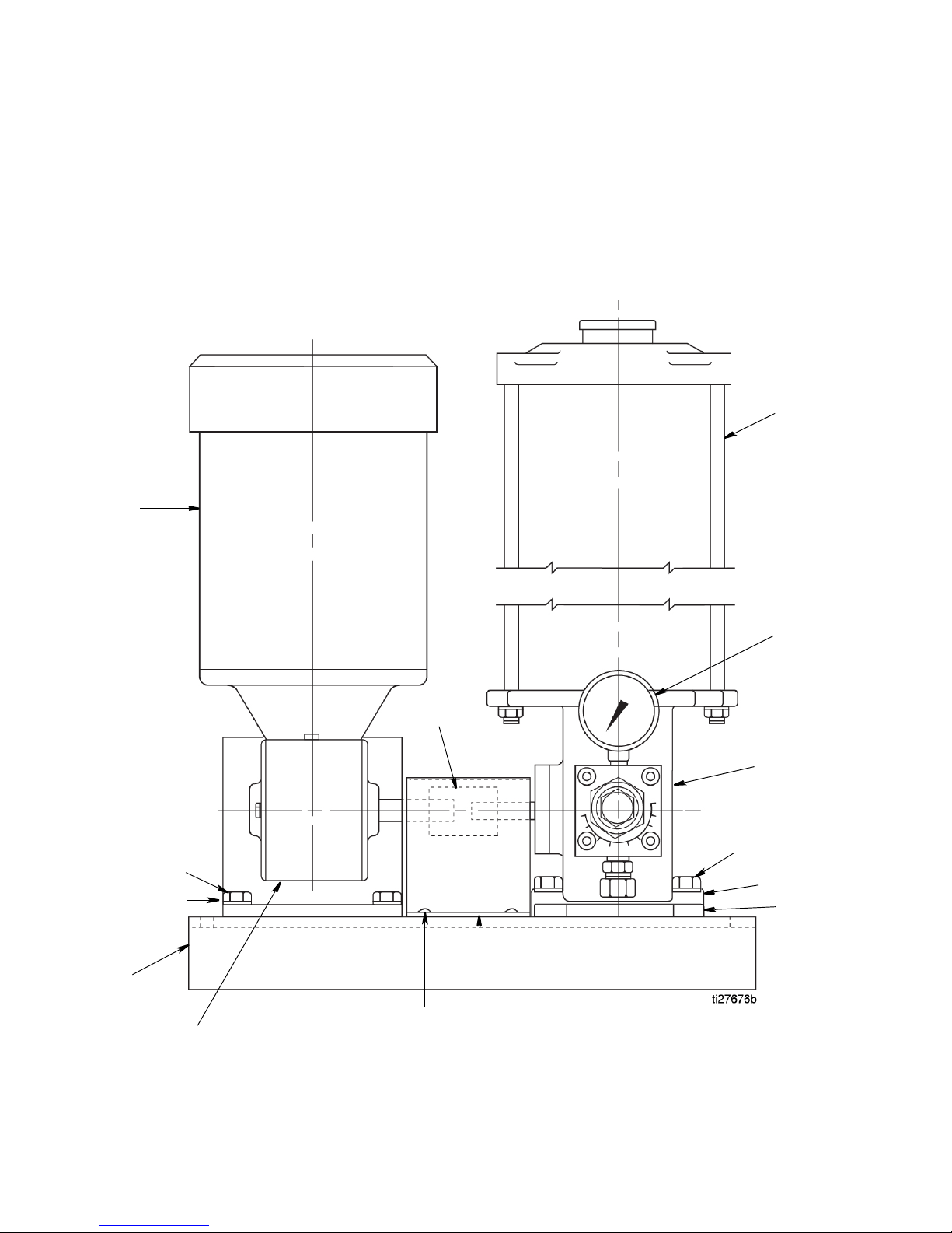
Parts
305
307d
307a
307w
307t
307g/
307h307r
307a
307d
307b/307m
303
302
307
301
Motorized LubeMaster Pump with Gear Reducer and Motor (Up to
20 lbs): Floor Mounting
563388 - Base, Floor Mounting 10:1
563389 - Base, Floor Mounting 60:1
3A2781A 31
Page 32
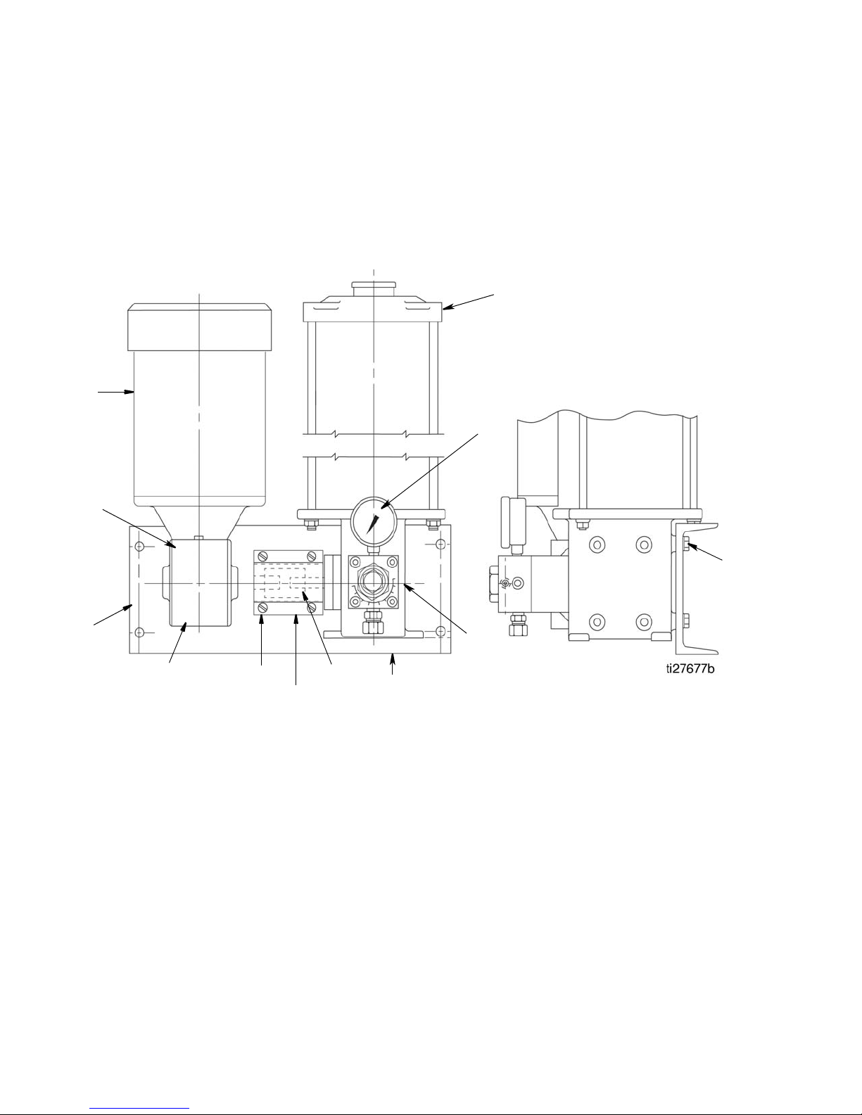
Parts
303
307c/
307y
307r
307g/
307h
307t
307m
307v
307a/
307z
302
301
307
305
Motorized LubeMaster Pump with Gear Reducer and Motor (Up to
20 lbs): Wall Mounting
563386 - Base, Wall Mounting 10:1
563387 - Base, Wall Mounting 60:1
32 3A2781A
Page 33
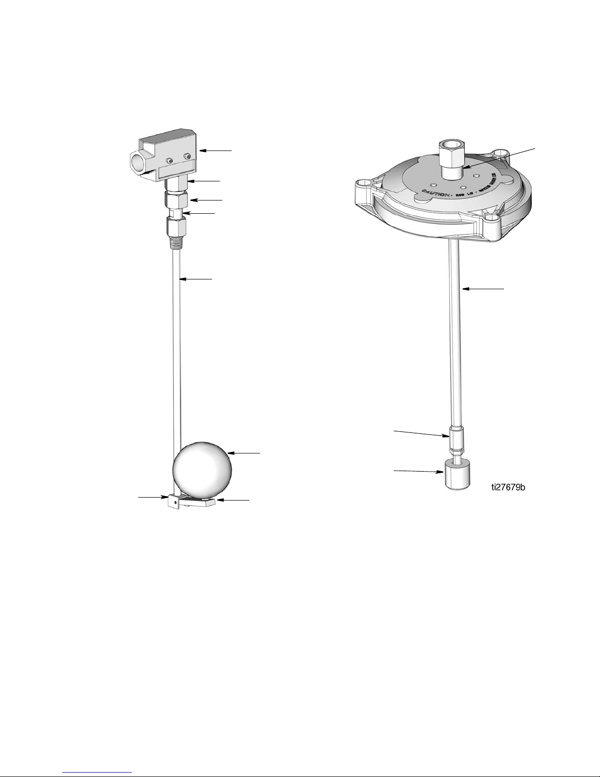
Parts
ti27678
304d
304a
304c
304b
304e
304h
304f
304g
304k
304m
304n
304p
Oil Reservoir 15 Amp Low-Level
Assemblies
Oil Reservoir 10-Watt Low-Level
Assemblies
Ref Part No. Description Qty.
304 563316 SWITCH, low level assy 5 & 12 pt
oil cyl
563317 SWITCH, low level assy 20 pt oil cyl
304a ADAPTER, switch, ll 1
304b ADAPTER, low level 1
304c FITTING, union, nut 1
304d SWITCH, limit, spdt 1
304e GUIDE, assy float rod 1
304f ARM, ll float 1
304g PIN, roll.093 dia 7/8 lg 1
304h FLOAT, spherical 1
WASHER, lock, int (not shown) 2
ROD (not shown) 1
SCEW, #8 - 32 x 1/2 slot phmach
(not shown)
Ref Part No. Description Qty.
304 563015 SWITCH, low level 12 pint
304 563016 SWITCH, low level 20 pint
304k ADAPTER 1
304m COUPLER, 1/8 x 11” 1
COUPLER, 1/8 x 18” 1
304n COUPLING, stl 1/8 npt 1
304p SWITCH, level mtg top 1
1
3A2781A 33
Page 34
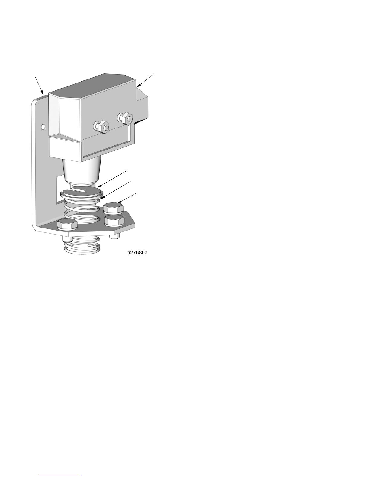
Parts
304u
304t
304v
304s
304r
Grease Reservoir Low-Level Assembly
Ref Part No. Description Qty.
304 563322 SWITCH, low level grease reservoir
304r SCREW, 1/4-20 x 3/8 hex hd
washer
304s RETAINER, cup spr 1
304t BRACKET, sw low lever paint 1
304u SWITCH, limit spdt 1
304v SPRING, primer filter 1
3
34 3A2781A
Page 35
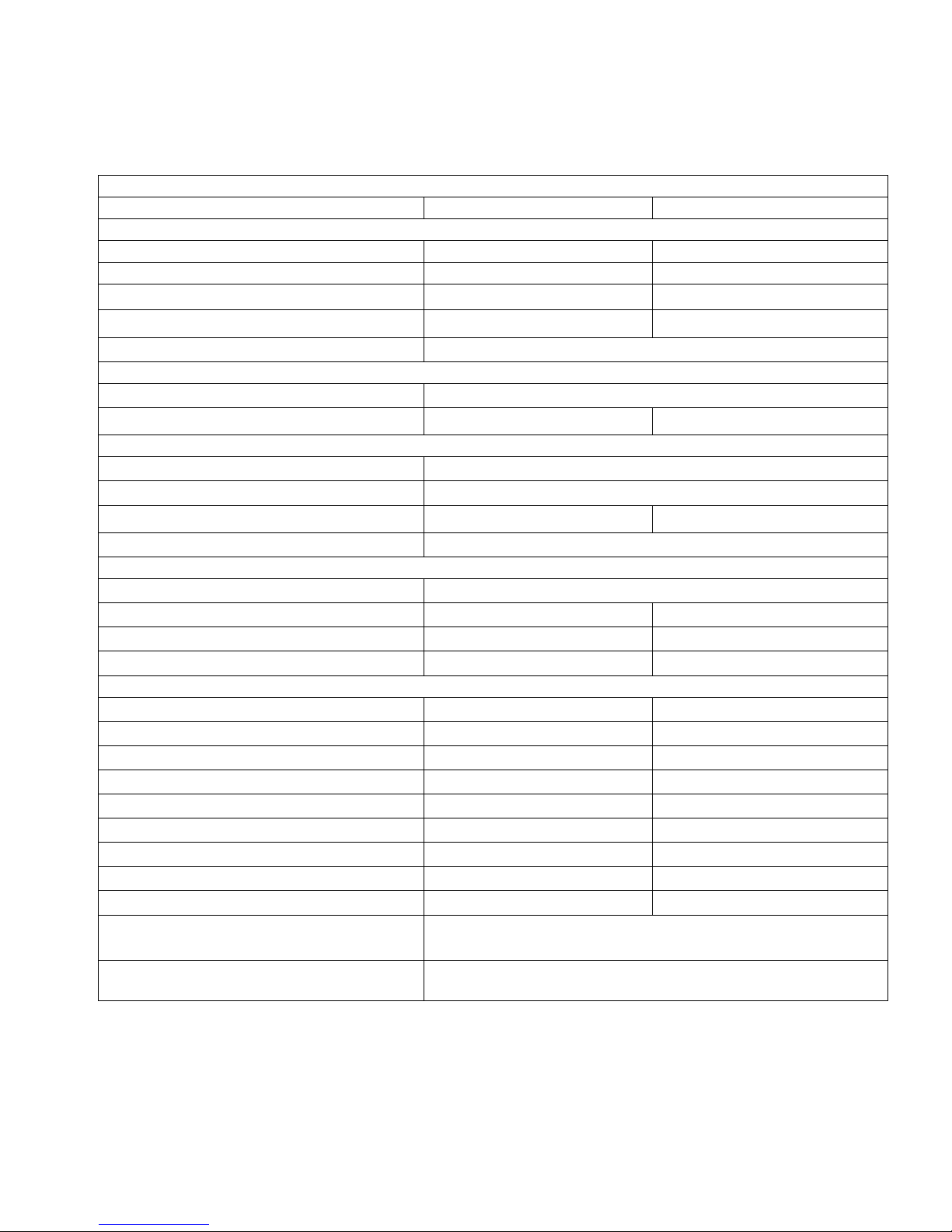
Technical Data
LubeMaster® Floor Mount or Wall Mount Pump Package
US Metric
Pump Data
Maximum fluid working pressure 5,000 psi 34 MPa, 340 bar
Max Torque @ Rated Max Pressure 27 ft-lbs 36.61 N.m
Output Range
Output per Stroke
Cycle Rate
Motorized Pump
Gear Ratios
Output Range
Clutch Drive Pump
Cycle Rate
Degrees of Throw
Output Range
Lubricants
Reservoirs
Material
Reservoir Capacities
Oil
Grease
Operating Temperatures
Reservoirs
Plastic
Metal
Oil
Grease
**NLGI #1
** NLGI #2
Options
Low Level (Ordering Code)
Code D - Pick 2
Code D - Pick 3
Code D - Pick 5
Code D - Pick 6
0.010 - 8.75 in.
0.010 - 0.050 in.
0.19 - 8.62 in.
0.100 - 75 in.
12 pint & 20 pint
12 lb & 20 lb
35°F to 135°F
20°F to 150°F
20°F to 150°F
20°F to 150°F
40°F to 150°F
SPTD, 15 amp @ 125, 250, 480 VAC; 1/2 amp @ 125 VDC;
3
per minute 0.1639 - 143.41 cm.3 per minute
3
0.1639 - 0.8195 cm.
1 - 175 strokes per minute
10:1 and 60:1 floor or wall mount
3
per minute
3.114 - 141.28 cm.
5 - 150 impulses per minute
12° to 60°
3
per hour
1.639 - 1,229.25 cm.
Oil or Grease
Plastic or Metal
5.68 liter & 9.46 liter
5.44 kg & 9.07 kg
1.7°C to 57.2°C
-6.7°C to 65.6°C
-6.7°C to 65.6°C
-6.7°C to 65.6°C
4.44°C to 65.6°C
1/4 amp @ 250 VDC
SPST, 10 watts @ 120 VAC
Technical Data
3
3
per minute
3
per hour
3A2781A 35
Page 36
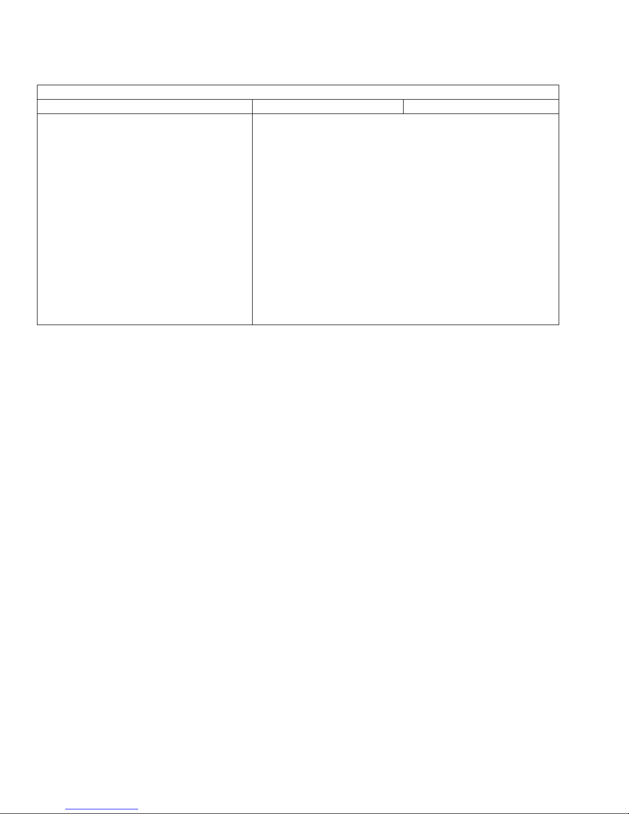
Technical Data
LubeMaster® Floor Mount or Wall Mount Pump Package
115/230V 1/2 hp single phase 60 Hz 1725 RPM, T.E. Full load running current 115 Volts, 7.4 Amps; 230 Volts, 3.7 Amps. Inrush at
115 Volts 49 AMPS; 230 Volts 24.5 AMPS.
230/460V 1/2 hp three phase 60 Hz 1725 RPM, T.E. Full load running current 230 Volts, 2 Amps; 460 Volts, 1 Amp. Inrush at 230
Volts 12.2 AMPS; 460 Volts 6.1 AMPS.
Motors (56 C-face)
115/230V 1/2 hp single phase 60 Hz 1140 RPM, T.E. Full load running current 115Volts, 7.8 Amps; 230 Volts, 3.9 Amps. Inrush at
115 Volts 49 AMPS; 230 Volts 24.5 AMPS.
230/460V 1/2 hp three phase 60 Hz 1140 RPM, T.E. Full load running current 230 Volts, 2.4 Amps; 460 Volts, 1.2 Amps. Inrush at
230 Volts 12.2 AMPS; 460 Volts 6.1 AMPS.
US Metric
* These recommended operating temperatures are based on materials used in construction of the pump and
reservoir only.
** The grease must be pumpable at the lowest anticipated operating temperature.
®
Loctite
is a registered trademark of the Loctite Corporation.
36 3A2781A
Page 37
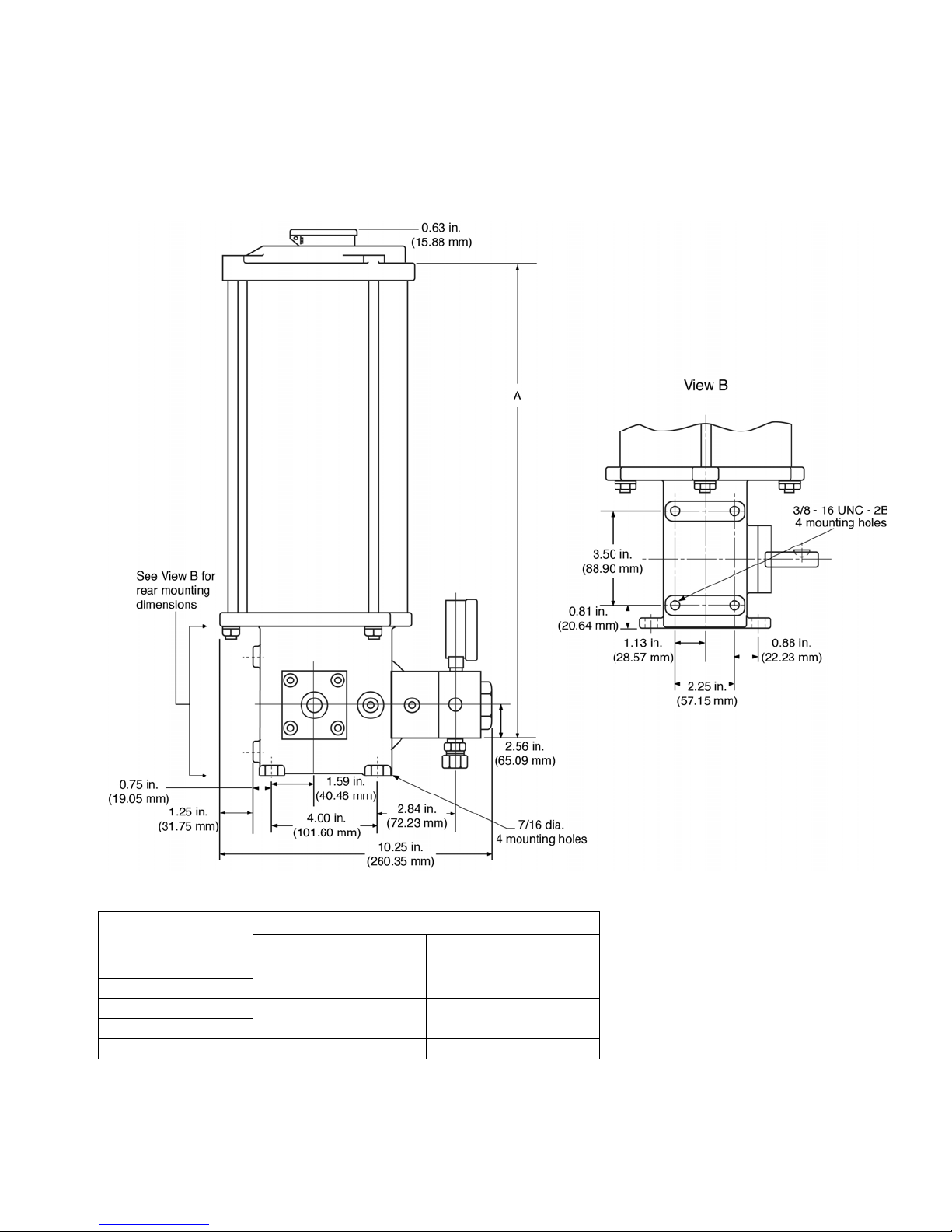
Dimensions
Reservoirs
Dimensions
Reservoir Size
12 Pint Oil
12 Lb. Grease
20 Pint Oil
20 Lb. Grease
Overhead Supply 7.66 194.5
3A2781A 37
Inches MM
A- Dimension
19.56 496.9
26.56 674.7
Page 38
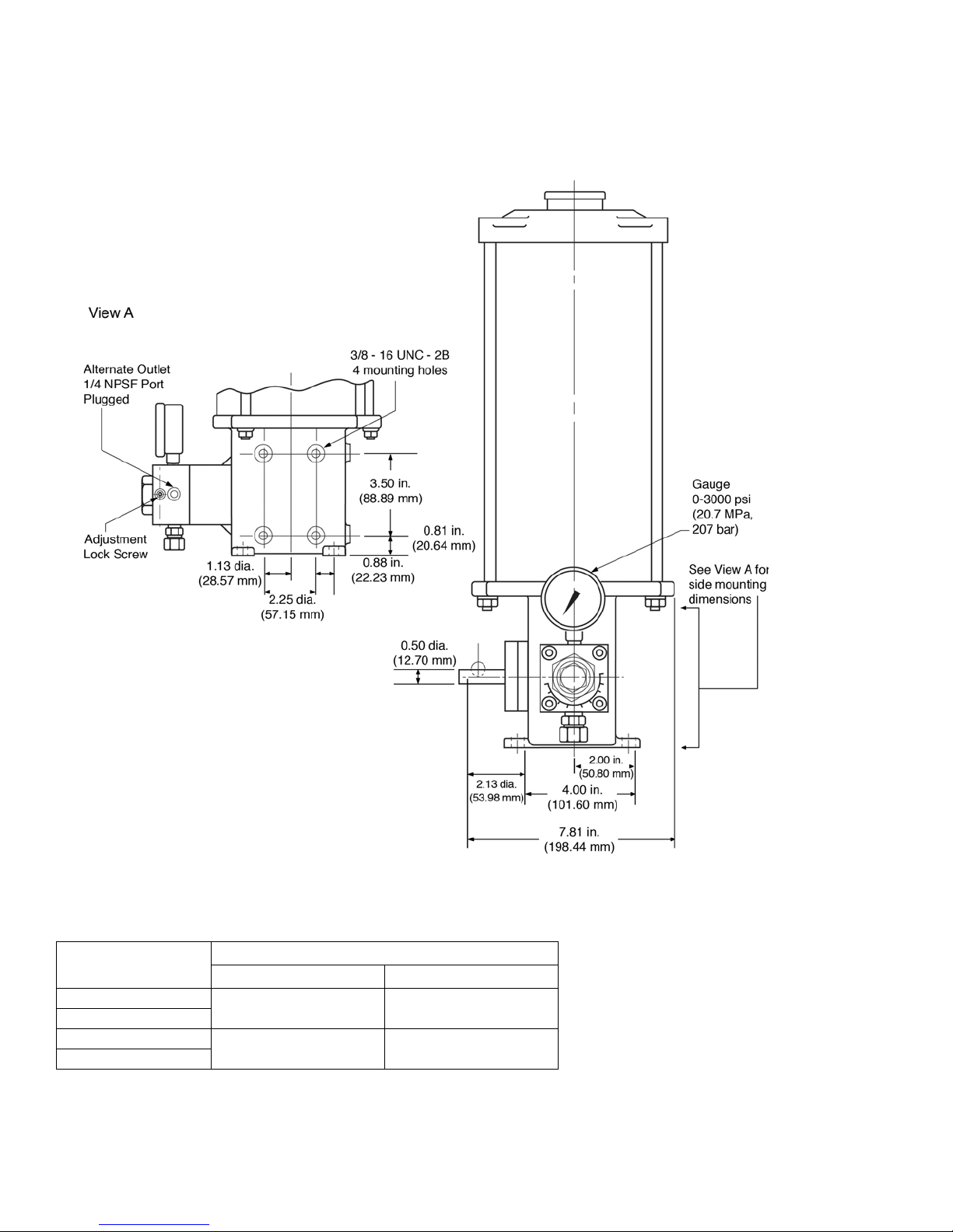
Dimensions
Reservoirs
Reservoir Size
12 Pint Oil
12 Lb. Grease
20 Pint Oil
20 Lb. Grease
38 3A2781A
Inches MM
19.56 496.9
26.56 674.7
A- Dimension
Page 39
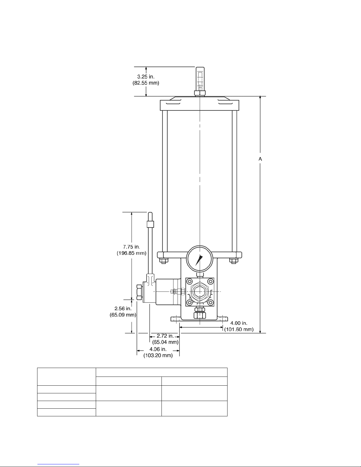
Clutch Drive
Dimensions
Reservoir Size
12 Pint Oil
12 Lb. Grease
20 Pint Oil
20 Lb. Grease
3A2781A 39
Inches MM
A- Dimension
19.56 496.9
26.56 674.7
Page 40
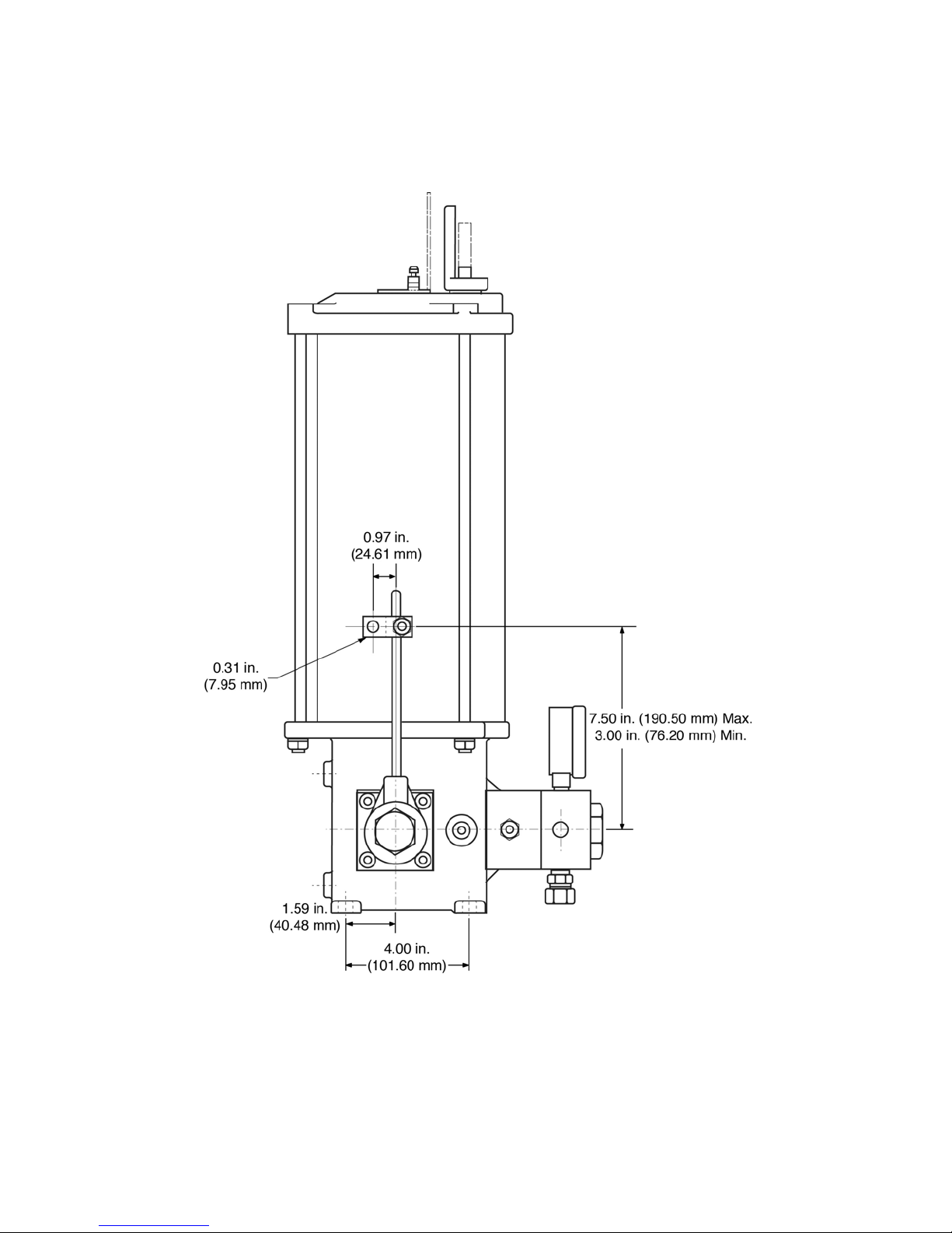
Dimensions
Clutch Drive
40 3A2781A
Page 41
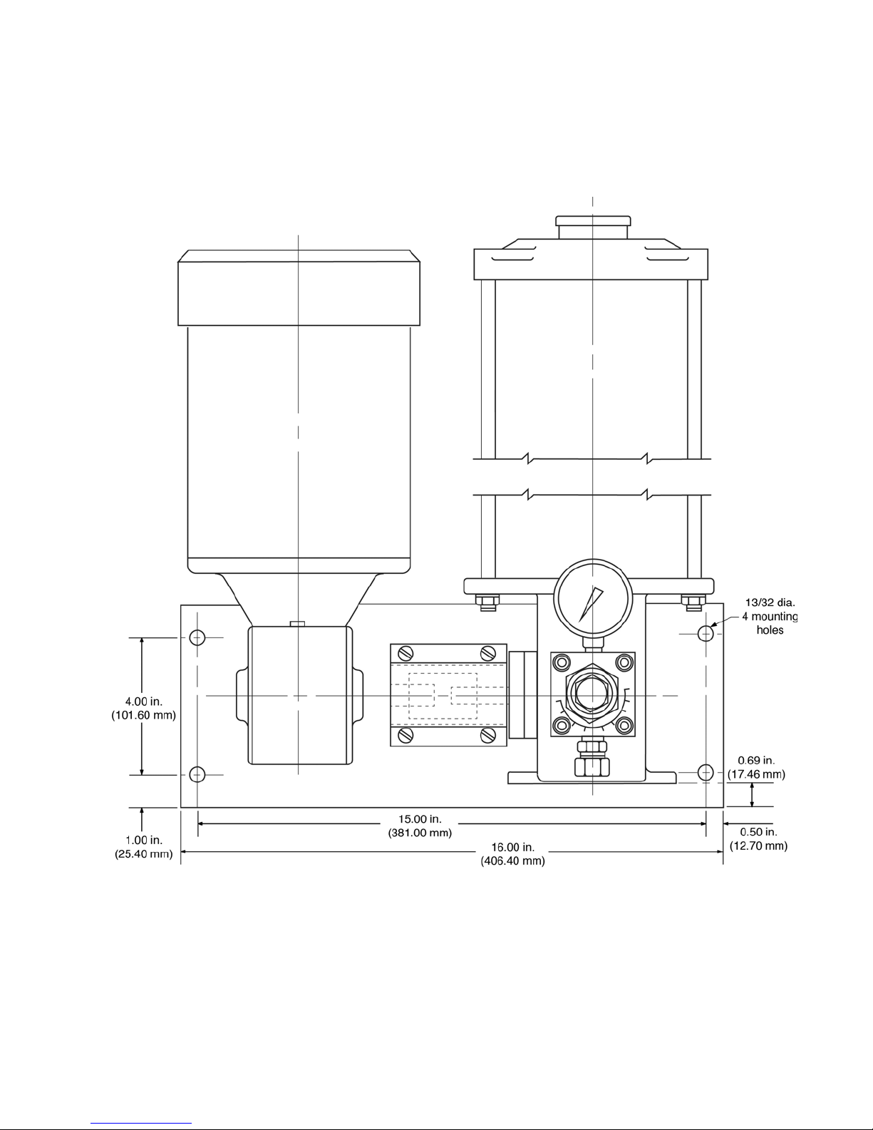
Motorized LubeMaster (Up to 20lbs): Wall Mounting
Inches (mm)
Dimensions
3A2781A 41
Page 42
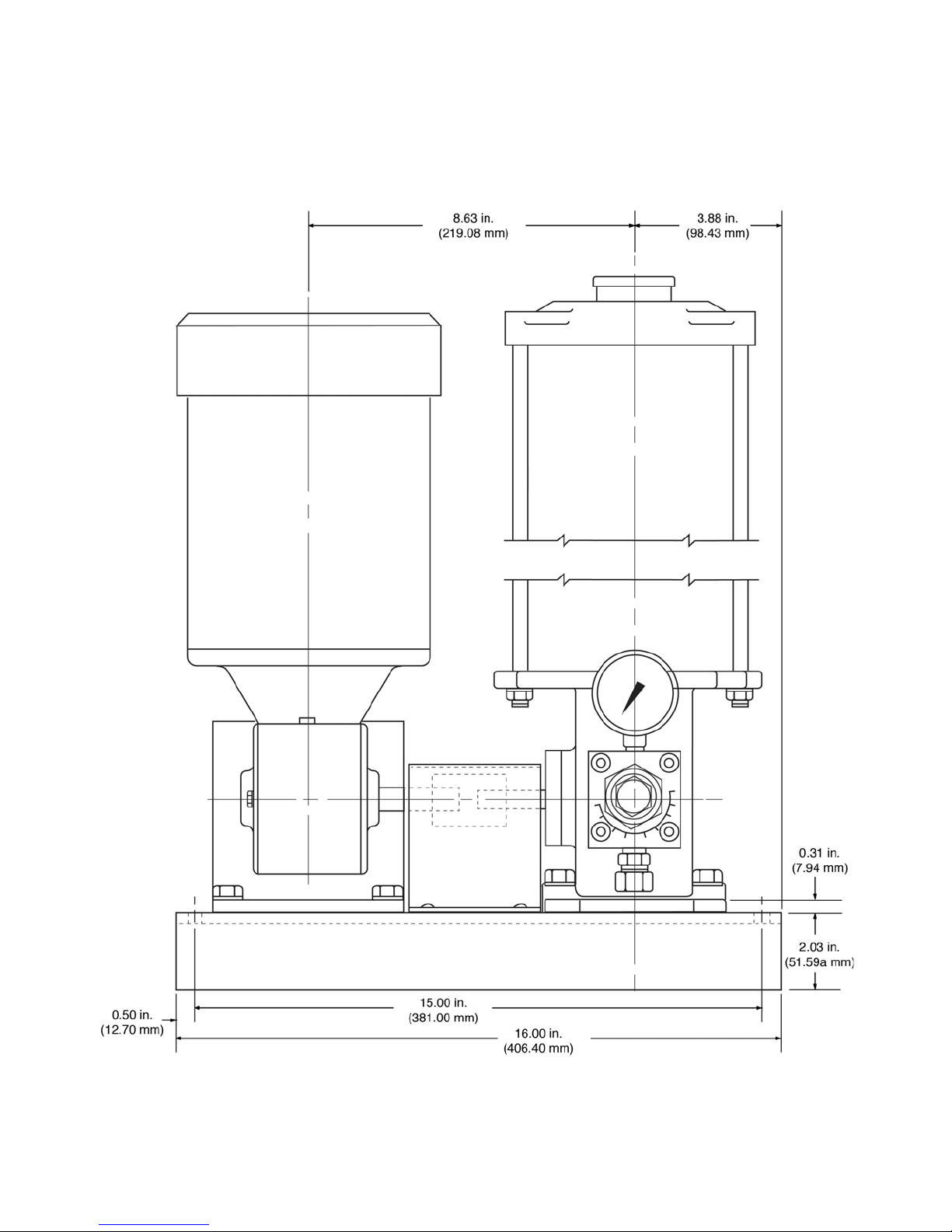
Dimensions
Motorized LubeMaster (Up to 20lbs): Floor Mounting
Inches (mm)
42 3A2781A
Page 43
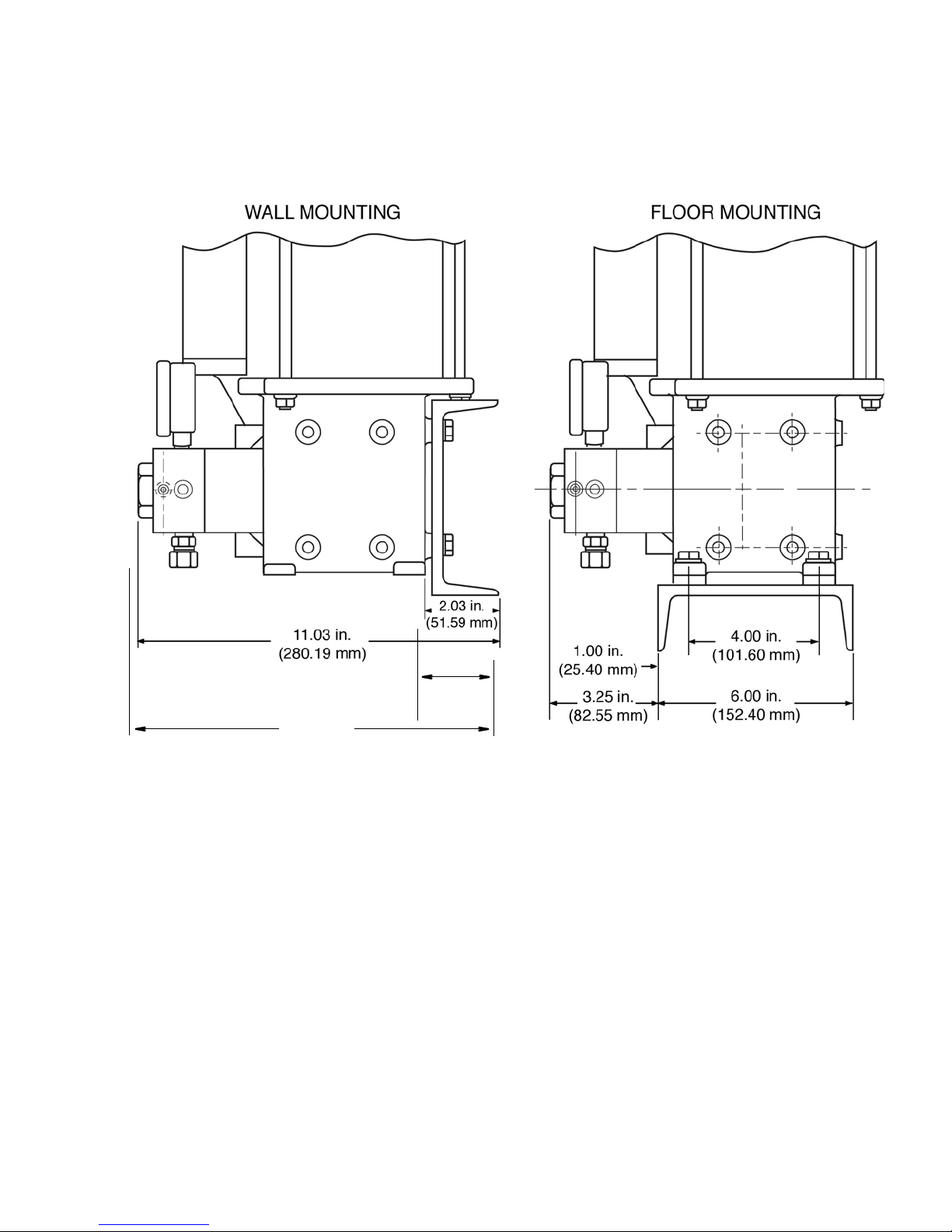
Motorized LubeMaster (Up to 20lbs)
2.03
(51.59)
11.03
(280.19)
Inches (mm)
Dimensions
3A2781A 43
Page 44

Graco Standard Warranty
Graco warrants all equipment referenced in this document which is manufactured by Graco and bearing its name to be free from defects in
material and workmanship on the date of sale to the original purchaser for use. With the exception of any special, extended, or limited warranty
published by Graco, Graco will, for a period of twelve months from the date of sale, repair or replace any part of the equipment determined by
Graco to be defective. This warranty applies only when the equipment is installed, operated and maintained in accordance with Graco’s written
recommendations.
This warranty does not cover, and Graco shall not be liable for general wear and tear, or any malfunction, damage or wear caused by faulty
installation, misapplication, abrasion, corrosion, inadequate or improper maintenance, negligence, accident, tampering, or substitution of
non-Graco component parts. Nor shall Graco be liable for malfunction, damage or wear caused by the incompatibility of Graco equipment with
structures, accessories, equipment or materials not supplied by Graco, or the improper design, manufacture, installation, operation or
maintenance of structures, accessories, equipment or materials not supplied by Graco.
This warranty is conditioned upon the prepaid return of the equipment claimed to be defective to an authorized Graco distributor for verification of
the claimed defect. If the claimed defect is verified, Graco will repair or replace free of charge any defective parts. The equipment will be returned
to the original purchaser transportation prepaid. If inspection of the equipment does not disclose any defect in material or workmanship, repairs will
be made at a reasonable charge, which charges may include the costs of parts, labor, and transportation.
THIS WARRANTY IS EXCLUSIVE, AND IS IN LIEU OF ANY OTHER WARRANTIES, EXPRESS OR IMPLIED, INCLUDING BUT NOT LIMITED
TO WARRANTY OF MERCHANTABILITY OR WARRANTY OF FITNESS FOR A PARTICULAR PURPOSE.
Graco’s sole obligation and buyer’s sole remedy for any breach of warranty shall be as set forth above. The buyer agrees that no other remedy
(including, but not limited to, incidental or consequential damages for lost profits, lost sales, injury to person or property, or any other incidental or
consequential loss) shall be available. Any action for breach of warranty must be brought within two (2) years of the date of sale.
GRACO MAKES NO WARRANTY, AND DISCLAIMS ALL IMPLIED WARRANTIES OF MERCHANTABILITY AND FITNESS FOR A
PARTICULAR PURPOSE, IN CONNECTION WITH ACCESSORIES, EQUIPMENT, MATERIALS OR COMPONENTS SOLD BUT NOT
MANUFACTURED BY GRACO. These items sold, but not manufactured by Graco (such as electric motors, switches, hose, etc.), are subject to
the warranty, if any, of their manufacturer. Graco will provide purchaser with reasonable assistance in making any claim for breach of these
warranties.
In no event will Graco be liable for indirect, incidental, special or consequential damages resulting from Graco supplying equipment hereunder, or
the furnishing, performance, or use of any products or other goods sold hereto, whether due to a breach of contract, breach of warranty, the
negligence of Graco, or otherwise.
FOR GRACO CANADA CUSTOMERS
The Parties acknowledge that they have required that the present document, as well as all documents, notices and legal proceedings entered into,
given or instituted pursuant hereto or relating directly or indirectly hereto, be drawn up in English. Les parties reconnaissent avoir convenu que la
rédaction du présente document sera en Anglais, ainsi que tous documents, avis et procédures judiciaires exécutés, donnés ou intentés, à la suite
de ou en rapport, directement ou indirectement, avec les procédures concernées.
Graco Information
For the latest information about Graco products, visit www.graco.com.
TO PLACE AN ORDER, contact your Graco distributor or call to identify the nearest distributor.
Phone: 612-623-6928 or Toll Free: 1-800-533-9655, Fax: 612-378-3590
All written and visual data contained in this document reflects the latest product information available at the time of publication.
GRACO INC. AND SUBSIDIARIES • P.O. BOX 1441 • MINNEAPOLIS MN 55440-1441 • USA
Copyright 2017, Graco Inc. All Graco manufacturing locations are registered to ISO 9001.
Graco reserves the right to make changes at any time without notice.
Original instructions. This manual contains English. MM 3A2781
International Offices: Belgium, China, Japan, Korea
Graco Headquarters: Minneapolis
www.graco.com
Revision A,
February 2017
 Loading...