

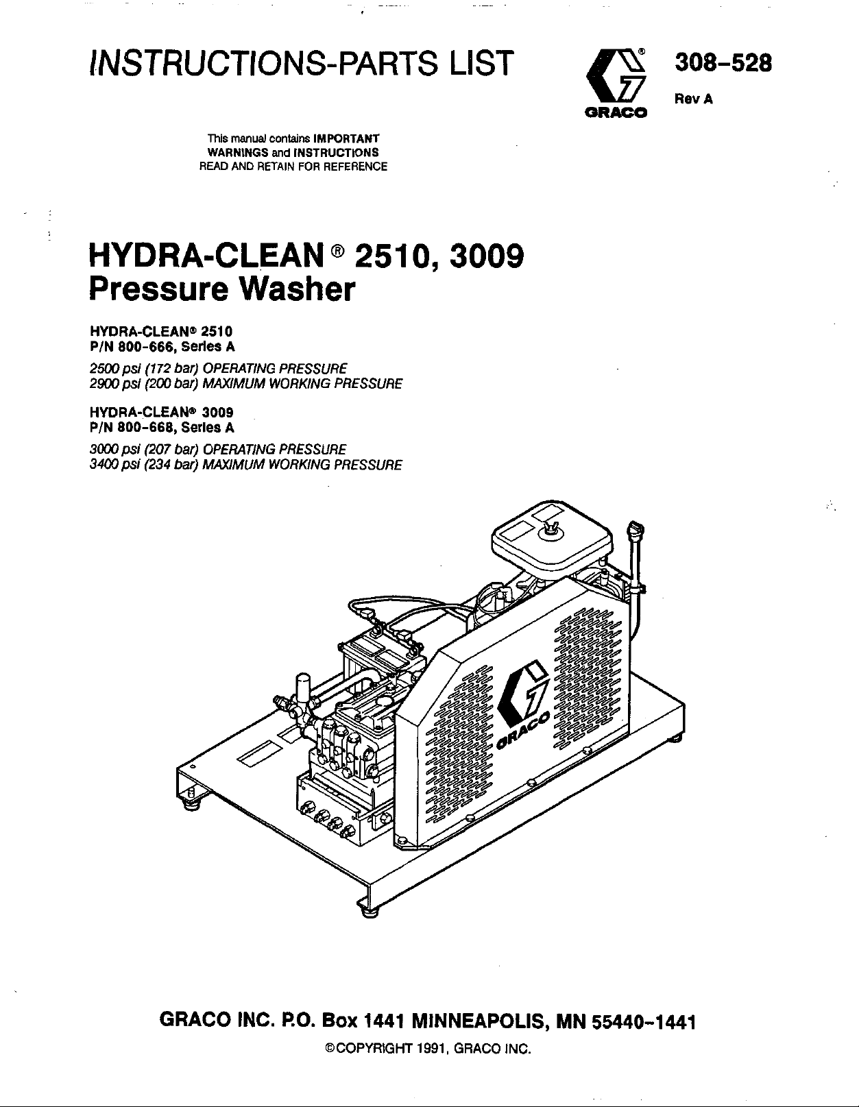
Page 1
INSTRUCTIONS-PARTS
This
manual
contains IMPORTANT
WARNINGS
READ AND
and
INSTRUCTIONS
RETAIN FOR REFERENCE
LIST
HYDRA-CLEAN
@
251
Pressure Washer
HYDRA-CLEAN@
PIN 800-666,
2500psi (172 bar) OPERATING PRESSURE
2900psi (200 bar)
HYDRA-CLEAN@'
P/N 800-668,
3000
psi
(207 bar) OPERATING PRESSURE
psi
3400
(234 bar)
2510
Series
Series
A
MAXIMUM
3009
A
MAXIMUM
WORKING PRESSURE
WORKING PRESSURE
0.3009
I
GRACO INC.
RO.
BOX
1441 MINNEAPOLIS, MN 55440-1441
@COPYRIGHT
1991,
GRACO
INC.
Page 2
WARNING
HIGH
FOR PROFESSIONAL
PRESSURE SPRAY
USE
CAN
ONLY. OBSERVE ALL
Read and understand all instruction manuals before operating equipment.
FLUID
General Safety
This pressure washer generates very high
pressure. Spray from
components can inject fluid through your skin and into
your body and cause extremely serious bodily injury
including the need for amputation.
splashed into the eyes or on the skin can cause serious
damage.
NNER
part of the body.
spray tip.
ALWAYS
cleaning or servicing any part of the sprayer.
NNER
body.
INJECTION
point the spray gun or wand at anyone or at any
follow the Pressure Rellef Procedure, before
try to stop or deflect leaks with your hand or
the
NNER
HAZARD
gun,
Also,
put hand
leaks or ruptured
fluid injected or
or
fingers over the
fluid
CAUSE SERIOUS INJURY.
WARNINGS.
Pressure Relief Procedure
To
reduce the risk of serious bodily injury, including
injection and splashing in the eyes or on the skin,
always follow this procedure whenever you stop
10
sprayingfor more than
and before checking or repairing any part of the system.
1.
Engage the trigger safety latch.
2.
Tum the sprayer
3.
Remove the ignition cable from the spark plug.
4.
Shut
off
the water supply.
5.
Disengage the trigger safety latch and trigger the
gun to relieve pressure, and then engage the trigger
safety latch again.
minutes, when shuttingdown,
off.
fluid
Be sure equipment safety devices are operating
properly before each use.
Medical Treatment
If
any fluid appears to penetrate your skin, get
EMERGENCY
NOT TREAT AS A SIMPLE
what fluid was injected.
NOTE TO PHYSICIAN: Injection
traumatic
surgically
treatment to research toxicity Toxicity is
concern with some exotic coatings injected
directly into the bloodstream. Consultation with a
plastic surgeon or reconstructive hand surgeon
may be advisable.
MEDlCALTREATMENTATONCE.DO
CUT.
Tell
the doctor exactly
in
the skin is
injuv.
It
is
as
soon
Important
as
to treat
posslble.
the
Do
not delay
Injury
a
a
6.
Before long-term (overnight) storage or
transporting of the unit, disconnect the water supply
and disconnect the fuel supply.
Spray
Be sure all gun safety devices are operating properly
before each
the gun; this can cause a malfunction and result
sefious bodily injury.
SAFETY
moment, always set the gun safety latch
or "safe" position, making the gun inoperative. Failure
properly
triggering of the gun.
SPRAY
cleaning or changing spray tips.
while spraying, engage the gun safety latch
immediately.
Procedure and then remove the spray tip
Gun
Safety
use.
LATCH:
set
the safety latch can result in accidental
TIP
SAFEPI:
ALWAYS
Devices
Do
not remove or modify any part of
Whenever you stop spraying for a
in
the engaged
Use extreme caution when
If
a spray tip clogs
follow the Pressure Relief
to
clean
in
to
it,
2
308-528
Page 3
FUEL AND
EMISSION
HAZARDS
NNER
me
spilled on a hot surface can ignite and cause a fire.
ALWAYS
NNER
exhaust contains carbon monoxide, a poisonous,
fill the fuel tank while the unit is running or hot.
fuel used in this unit is combustible and when
fill tank slowly
operate the unit in a closed building. The
to
avoid spilling.
EQUIPMENT MISUSE HAZARD
General Safety
Any misuse of the pressure washer or accessories,
such as overpressurizing, modifying parts, using
incompatible chemicals and fluids,
damaged parts, can cause them
fluid injection, splashing in the eyes or on the skin, or
other serious bodily injury, fire, explosion or property
damage.
NNER
so
CHECK
replace wom or damaged parts immediately.
ALWAYS
clothing.
the
alter
or
modify any part of this equipment; doing
could cause it to malfunction.
all spray equipment regularly and repair or
wear protective eyewear and appropriate
If
using a chemical injector, read and follow manufacturer's literature before using any chemical in
chemical manufacturer's literature for
or
using wom
to
rupture and result
or
in
odorless, invisible gas which can cause serious injury
if
or death
NNER
factory
the
pressure washer and will void the warranty.
recommendations on additional protective equipment,
such as
System
nis sprayer can develop high operating pressures. Be
sure that all spray equipment and accessories are rated
to
withstand
sprayer.
pressure of any component or accessory
system.
inhaled.
alter the maximum throttle setting, which is
set.
Tampering with this adjustment can damage
a
respirator.
Pressure
the
maximum working pressure of this
DO
NOT
exceed the maximum working
used
in
the
Chemical Compatibility
BE
SURE
injector are compatible with
hose, gun, wand and tip, as given in the Technical Data
(inside back cover). Always read the chemical
this pressure washer.
that ail chemicals used in the chemical
the
wetted parts
of
the
~..
HOSE SAFETY
High pressure fluid in
If the hose develops a leak, split or rupture due
kind of wear, damage or misuse, the high pressure
spray emitted from
other serious bodily injury or property damage.
ALL FLUID HOSES MUST HAVE STRAIN RELIEFS ON
BOTH ENDS.
from
kinks
or
bends
can result in hose rupture.
TIGHTEN
use. High pressure fluid can dislodge a
or allow high pressure spray
coupling.
all fluid connections securely before each
the
hoses
can
be very dangerous.
it
can cause a fluid injection injury or
The
strain reliefs help protect the hose
ai
or close to the coupling, which
loose
to
be emitted from the
to
any
coupling
NNEfl
entire hose for cuts, leaks, abrasion, bulging cover, or
damage
these conditions exist, replace
DO
with tape or any other device.
contain the high pressure fluid.
HANDLEAND ROVTEHOSES CAREFULLY
on
chemicals which are not compatible with the inner tube
and cover of the hose.
temperatures above
(-400
use a damaged hose. Before each
or
movement of the hose couplings.
the
hose immediately.
NOT
try
to
recouple high pressure hose
A
repaired hose cannot
hoses
to
move the pressure washer. Do not use
DO
NOT
expose Graco hose
200"
F
(93'
C)
C).
use,
or
Do
or below
check
If
any
mend it
not pull
-40"
of
to
F
308-528
3
Page 4
MOVING
PARTS
HAZARD
Moving parts can pinch or amputate fingers or other
body parts.
or operating the pressure washer. high pressure fluid from
NEVER
and interlocks installed and functioning. Follow the
KEEP
operate
CLEAR
Ihe
of moving parts
pressure washer without all guards
when
starting
Pressure Relief Procedure
servicing the pressure washer to prevent discharging
the
before checking or
gun.
TERMS
WARNING:
that could cause bodily injury. that could cause damage
NOTE
Alerts
user
to avoid or correct conditions
Identifies helpful procedures and information.
CAUTION
Alefts
user to avoid or correct conditions
to
the equipment.
IMPORTANT
United States Government safety standards have been adopted under the Occupational Safety and Health
standards-particularly the General Standards, Part 1910, and the Construction Standards, Part 1926-should be
consulted.
Act.
These
4
308-528
Page 5
INSTALLATION
HIGH
PRESSURE
HOSE
CONNECflON
QUICK
COUPLER
Figure
Check
Check the unit for any damage that may have occurred
in shipping. Notify
any damage.
Set
Fill the battery cells with electrolyte and water. Charge
the
and secure. Connect the fuel line
quick coupler provided. Squeeze the priming
times.
install it between the pump unloader and the high
pressure hose, using
Connect the high pressure hose between the pump
outlet and the gun inlet. Both of these connections are
made with quick couplers.
1
for
Shipping
Damage
the
carrier immediately
if
there
is
Up
battery. Be sure the battery connections are correct
to
the engine using the
bulb
3
to
5
If
you are using a downstream chemical injector,
the
quick couplers provided.
CAUTION
lo
100
fl
Up
beused. Longer hoses may affect sprayer
performance, and chemical injector performance,
if
used.
InStall the appropriate spray tip on the wand. See
Installing and Changing Spray Tips. If you are using a
sandblaster kit, see its separate manual for installation
instructions.
(30 m) of high pressure hose may
Connect
to
Water Supply
CAUTION
Before attaching
local plumbing code regarding cross-connection
to
the water supply.
801-133, is available to prevent backflow of
contaminated water into the fresh water supply.
Install it upstream from the pump.
If inlet water pressure is over
regulating water valve,
installed at the garden hose connection.
Do not exceed 160° F
temperature.
Connect a hose with at leasl a 3/4 inch (19 mm) ID from
the water supply
supply hose should not be more than
NOTE: The water source at the unit
minimum flow rate equal
Technical Data, inside back cover).
not possible, a water holding tank must be
added
to
the water supply, check your
A
backflow preventer, P/N
60
psi
P/N
800-258, must be
(70"
C) inlet water
to
the
unit's 3/4
to
prevent pump damage.
inch
NPT inlet. The
50
to
that
(4.1
bar) a
fl(l5
m) long.
must
have a
of
the unit (see
If
this is
308-528
5
Page 6
Always
is started safely and properly.
1.
NOTE:
2.
use
this startup procedure
Check oil levels.
Engine: Add SA€
as necessary.
Pump: Add SAE
as necessary.
This pressure washer is equipped with a
low-oil sensor that shuts the engine
oil level falls below a certain level. If the unit
stops unexpectedly, check both the oil and
the fuel levels. Check the oil level each time
the unit
Check
fuel
is
refueled.
level.
30
or 1 OW-3OweigM detergent oil
20
or
30
to
ensure that the Unit
weight non-detergent oil
off
WARNING
DO
NOT refuel a hot engine. Refueling a hot
engine could cause a fire. Use only fresh, clean
regular or unleaded gasoline. Close the fuel
shutoff valve during refueling.
3.
Turn on the water supply.
if the
If
the engine is cold, completely close the engine
choke. Press
choke may have
seconds before opening it to keep the engine
running. Otherwise, open the choke as soon as the
engine starts.
If the engine is warm, leave the choke open or
partially closed. Start the engine as described in the
preceding paragraph. When the engine starts. be
sure
to
open the choke completely.
7.
ALWAYS
whenever you stop spraying, even for a moment,
reduce the risk of fluid injection or splashing
eyes or on the skin if the gun is bumped or triggered
accidentally.
8.
ALWAYS
costly damage
7
DONOTaliowthe pressure washer
than
10
recirculating water to overheat and seriously
damage the pump. Tum
will not be spraying or cleaning at least every
minutes.
time further.
If
the
start button.
to
be kept closed for
engage the gun's trigger safety latch
observe the following
to
the pressure washer
in
cool weather, the
10
CAUTIONS
to avoid
CAUTION
to
idle for more
minutes. Doing
heated inlet water is used, reduce this
so
may cause the
off
the pressure washer
to
in
if
10
30
to
the
it
Never run the unit dry, Costly damage to the pump
completely tumed on before operating.
I
will result. Always be sure the
4.
Trigger the gun until water sprays from the tip
indicating that the air is purged from the system.
5.
Be
sure the spark plug ignition cables are pushed
firmly onto the spark plugs. The ignition shutoff
switch should be in the "on" position. The throttle
should be in
6.
Start
NOTE
the engine.
For easier starting, have one person start the
pressure washer while another person
triggers the spray
the
"run" position.
1
water supply is
gun.
DO
NOT run the pump dry, which will quickly
damage the pump.
fully tumed on before starting the pump.
DO
NOT operate the pressure washer without an
inlet water screen. This screen helps keep
abrasive sediment
clog or scratch the pump. Keep this screen clean.
DO
NOT pump caustic materials; such materials
may corrode the pump components.
9.
See the chemical injector or sandblaster kit manual
for detailed cleaning information
accessories are used.
Be
sure the water supply is
out
of the pump, which could
if
these
6
308-528
Page 7

-
Trigger Safety
Latch
WARNING
To
reduce the risk of serious bodily injury,
including fluid injection, splashing in the eyes or
on the skin,
latch whenever spraying stops, even for a
moment.
In the engaged position, the trigger safety latch
prevents the gun Nom being triggered accidentally
by hand or if
latch is pushed fully down when engaging
cannot prevent the gun
Figure
2.
ALWAYS
it
is
engage
the
trigger safety
dropped or bumped. Be sure the
from
being triggered. See
it
or it
Installing and Changing Spray
Tips
WARNING
1.
Follow the
2.
Point the gun and wand away from yourself and
anyone else.
3.
Without holding your hand over the spray tip
pull back the quick coupler ring (e). Remove the old
tip and/or install a new one, and then release the
ring. See Figure
4.
Be sure the tip
again.
5.
Tip holding holes are provided on the chassis.
TO
avoid blowing the O-ring out
coupler, due
never operate the pressure washer without a tip
securely mounted in the quick coupler.
Pressure
to
Relief Procedure.
3.
is
secure before starting to spray
of
the quick
the high pressure in the system,
(A),
TRIGGER SAFETY LATCH SHOWN ENGAGED
TRIGGER SAFETY LATCH SHOWN DISENGAGED
Figure
2
Figure
3
308-528
7
Page 8

SHUTDOWN, FLUSHING
'AND STORAGE
WARNING
Pressure
To reduce the risk of serious bodily injury,
including fluid injection and splashing
or
on the skin, always follow this procedure
whenever you stop spraying for more than
minutes, when shutting down, and before
checking or repairing any part of the system.
1.
2.
3. Remove the ignition cable from the spark
4.
5. Disengage the trigger safety latch and trigger
6.
If
the pressure washer will be exposed
temperatures, drain all water
must be stored in freezing temperatures, flush the
unit with a
pressure. Flush the pressure washer before using it
again to remove the anti-freeze.
NOTE:
Rellef
Procedure
in
the eyes,
10
Engage the trigger safety latch.
Turn
the sprayer
plugs.
Shut
off
the water supply.
the gun
the trigger safety latch again.
Before long-term (overnight) storage or
transporting of the unit, disconnect the water
supply, and disconnect the fuel supply.
to
An
anti-freeze flush kit, P/N 802-327,
available
off.
relieve pressure, and then engage
to
freezing
out
of the pump. If it
50%
anti-freeze solution. Relieve
to
make flushing easier.
is
MAINTENANCE
Observing regular maintenance intervals helps ensure
that you get maximum performance and life from the
pressure washer.
There is a break-in period for
After changing the oil
their respective break-in periods, the interval between
required changes is longer.
If
the unit is operating in dusty conditions, these
maintenance checks should be made more often.
in
WARNING
To reduce the risk of serious bodily iniury,
including fluid injection, splashing in the eyes or
on the skin or injury from moving parts, always
follow the
before proceeding.
Daily
After first 5
hours of
Each 25 hours
of operation
After first
hours of
Pressure
50
Relief
What to
Clean water inlet screen and
filter. Check engine and pump
levels. Fill as necessary. Check
oasoline level. Fill as necessarv.
Change engine break-in oil.
Drain
30 or 1OW-30 detergent oil.
Clean and remove air cleaner
foam. Wash with water and
detergent. Dry thoroughly.
with oil and squeeze
oil.
Change pump break-in oil.
SAE
20
tne
engine and pump.
these components following
Procedure Warnlng
1
do
oil
oil
when warm.
or 30 non-detergent oil.
Use
SAE
Rub
to
distribute
Use
If
water does freeze in the pressure washer, thaw it
to
in a warm room before trying
pour
hot
water on or into the pump;
ceramic plungers!
2.
After each
washer with a clean, damp cloth.
3. Perform the appropriate maintenance. See
maintenance chart.
6
308-528
use,
wipe all surfaces of the pressure
start it.
it
may crack the
DO
NOT
Each
100
hours
of operation
or 3 months
Each
500
hours
of operation
Clean or replace paper air
cleaner cartridae. TaD aentlv
remove
Use
dirt.
Cfiange'.eEgine'oil.
SAE 30 or 1OW-30
to
I
I
Page 9

TROUBLESHOOTING
To
reduce the riskof
moving
parts,
serious
always
follow the
CHART
WARNING
bodily
injury,
includingfluid injection,
Pressure Relief Procedure Warnlng
splashing
before
inthe
eyes
proceeding.
or
on
the skin
or
injury
from
Problem
Engine will
IS
hard to start
Engine misses or
lacks power
COW
pump runs rough
Water leakage
under pump manifold
Water in pump
Frequent or
premature failure of
the packings
Strong
inlet and low pressure
3n
the discharge side
not
start
pessure andlor
from
surging
at
the
M
Cause
No gasoline
Low oil level.
StarVStop switch in Stop position.
Water
Lwse
Battery not properly charged.
Choked improperly. Flooded engine.
Dirty air cleaner filter.
Spark
Spray gun closed.
Partially plugged air cleaner filter.
Spark plug dirty, wrong gap or wrong type.
lnconecl
Worn
Inlet filter Clogged.
Worn packings, abrasives
wear.
Inadequate water suppiy.
Belt slippage.
Fouled or dirty inlet
a smaii particle can
Restricted inlet.
Worn inlet
Leaking
Wom packings.
Humid air condensing inside crankcase.
Worn
Oil seals leaking.
Scored, damaged or wom plungers.
Abrasive material in the fluid being pumped.
Inlet water temperature
Overpressurizing pump.
Excessive pressure due
damaged
Pump running too long without spraying.
Running pump dry.
Foreign
valve or wom inlet and/or discharge valves.
in
fuel
tank or carburetor.
in
gasoline or old fuel.
or wrong battery connection.
plug
dirty, wrong gap or wrong type.
ignition timing.
or
wrong
size
tip.
in
water or natural
or
discharge valves. Even
cause
the valve to stick.
or discharge vaives.
high
pressure
packings.
hose.
too
high.
to partially plugged or
tip.
particles
in the inlet or discharge
Solution
Fill the tank with gasoline, open fuel shut
Check fuel line and carburetor.
Add
to proper level.
Move switch
Drain fuel tank
dry spark plug.
Check and tighten battery connections.
Check electrolyte level of cells, recharge battery.
Open choke and crank engine several times to
clear out gas.
Remove and ciean.
Clean, adjust the gap or replace.
Trigger spray gun.
Remove and ciean.
Clean. adjust the gap or replace.
Time engine.
Replace
Clean. Check'more frequently.
Check filter. Replace packings.
SERVICE.
Check water flow rate
Tighten or replace;
both at same time.
Clean inlet and discharge valve assemblies. Check
filter.
Check garden hose. may
Replace wom valves.
Replace'high pressure hose.
Install new packings.
3hange oil as specified in MAINTENANCE.
nStali new packings.
nstail new oil seals.
Install new plungers.
Install proper filtration on pump Inlet plumbing.
Check watertemperature; may not exceed
Do
not
EQUIPMENT MISUSE HAZARD.
Clean or replace
Spray
Never
spraying.
not
Do
Clean or replace valves.
to
start position.
and
carburetor. Use new fuel and
with tip of proper size.
See
to pump.
USB
wrrect
belts
be
collapsed or kinked.
See
PUMP SERVICE.
See
PUMP SERVICE.
See
PUMP SERVICE.
See
PUMP SERVICE.
modify any factory-set adjustments.
tip.
See
Installing and Changing
Tips.
run
pump more than
run
pump without water.
10
minutes
See
PUMP SERVICE.
off
valve.
PUMP
and replace
16OOF.
See
without
308-528
9
Page 10

PARTS
800-666
DRAWING
Hydra-Clean@
2510
Pressure
Washer
10
308-528
Page 11

PARTS
800-666
LIST
Hydra-Clean@
2510
Pressure Washer
REF
NO.
1
2
3
4
5
6
7
8
9
10
11
12
13
14
15
16
17
18
19
20
21
22
23
24
25
26
27
28
29
30
31
32
33
34
35
36
37
38
39
40
41
42
43
44
PART
NO.
800-643
803-788
801-940
100-214
100-023
803-872
102-547
802-784
803-591
802-026
804-049
801 -823
803-812
803-806
803-797
801 -790
803-517
802-084
HUB, Engine
BELT. Drive
HUB,'
SHEAVE, Pump
PUMP, 2500 psi
LABEL, Keep From Freezing
NIPPLE.
TEE., -3~4
801 -787
802-096
803-141
803-1 42
802-025
801 -71 6
801
-008
801-568
800-323
803-791
156-849
803-787
803-781
100-321
800-642
803-817
100-307
100-133
100-132
802-845
803-881
801-571
172-981
BUSHING, 314 x 112
HOSE,
NIPPLE, Hex,
TANK. Fuel.
LABEL, WainiG,
LABEL, Graco G
QUICK COUPLER, Male 318
UNLOADER, 2500 psi
CAPLUG,
NIPPLE, Hex 3/8
BRACKET. Pumo mountina
NBE, pump mounting
NUT, Lock, 1/2-13
BRACKET, Rail stiffener
BOLT, Eye
NUT, Hex, 3/8-16
WASHER, Lock, 318
WASHER, Flat, 3/8
FOOT, Rubber
FUEL LINE, w/Connector,
HOSE, High pressure, 318
LABEL. Wamina. chassis
176-250
800-652
801 -569
318 NPT
Pump 1
314
_.
~ ~ ~
Bypass
x
Inlet,
x 2 1
112
6
aallon
3/4
(see
NPSM 1
fuel
page 14) 1
tank
'
114
X
50'
ON
1
1
6
6
6
1
4
6
14
1
1
1
2
1
1
1
1
1
1
2
2
1
2
6
6
10
4
1
1
1
REF
NO.
45
46
47
48
49
50
51
52
53
54
55
56
57
58
59
60
61
62
63
64
65
66
67
68
69
70
71
72
73
74
75
76
n
78
79
80
81
82
83
84
85
PART
NO.
156-082
803-350
801-134
801 -674
801-009
154-594
801 -972
803-525
107-069
801 -954
100-527
100-01 6
100-015
801 -960
801-959
801 -958
803-867
803-077
802-408
181 -867
802-363
802-908
801-919
803-891
801 -971
800-375
800-392
801
-548
800-404
800-405
800-493
800-494
803-894
803-868
801 -090
801 -759
801 -758
803-697
803-698
155-665
803-781
DESCRIPTION
QN
O-RING, Quick couDler. 3/8
GUN, Spray
(see
3d8-511) 1
WAND. 32l
SLEEVE, 28" 1
QUICK COUPLER, Female, 1/4
O-RING, (incl.
PAD. Banem
5ob
utck ' coupler, 114 1
-~,
BOLT, Battery
BRACKET, Battery
BATTERY, 12 Volt,
WASHER. Flat.
.
~,
BOLT, Carriage, 1/4-20
30
amp
1/4
.
~.
x
1
TERMINAL PROTECTOR, Black
TERMINAL PROTECTOR,
Red
CABLE. 26 Lona 1
CABEL,'
ElectTolyie
CABLE. 32 Lono
LABEL,'w~~~~~LABEL, Caution
CONNECTOR, Fuel
BRACKET. Fuel Connector
LINE.
Fuei~
.
1/4
-.
,
.
Hose
,
.
-.
.
.
-,
CLAMP,
HOSE ASSEMBLY, w/Quick
couplers (incl. 26,
GUN & WAND ASSEMBLY
(incl. 29,44,46,47,
~"
40,
44)
48,
49)
GROMMET. Rubber 4
TIP
ASSEMBLY
0013
(incl. 79, 80)
TIP
ASSEMBLY 1513
(incl. 79,81) 1
TIP
ASSEMBLY 2513
(incl. 79, 82)
TIP ASSEMBLY 4013
(incl.
CAPLUG,
70, 83) 1
Ouilet,
318
ENGINE, 24 Hp Onan,
electric
statt
QUICK COUPLER, Male, 114 4
TIP, Spray 0013 1
TIP,
Spray 1513
TIP. SDrav 2513 1
TIP;
Sprai
4013
SWIVEL, 318
SPACER, Pump Bracket 2
1
1
1
1
2
1
1
2
2
1
1
1
3
1
1
1
1
1
1
1
1
1
308-528
11
Page 12

PARTS
800-668
DRAWING
Hydra-Clean6
3009
Pressure Washer
12
308-528
Page 13

PARTS
800-668
LIST
Hydra-Clean@
3009
Pressure Washer
REF
NO.
1
2
3
4
5
6
7
8
9
10
11
12
13
14
15
16
17
18
19
20
21
22
23
24
25
26
27
28
29
30
31
32
33
34
35
36
37
38
39
40
41
42
43
44
PART
NO.
800-643
803-788
801 -940
100-214
100-023
803-872
102-547
802-784
803-591
802-026
802-1 17
801
-823
803-812
803-806
803-797
803-814
803-517
802-084
801 -787
802-096
803-141
803-142
802-025
801
-71 6
801
-008
801
-568
800-324
803-791
156-849
803-787
803-781
100-321
800-642
803-817
100-307
100-133
.100-132
802-845
803-881
801-571
172-981
176-250
800-652
801
-569
DESCRIPTION
CHASSIS
BELT GUARD
SCREW. Can
5/16-i8 ~'314
WASHER, Lock, 5/16
WASHER, Flat, 5/16
LABEL, Graco G
SCREW, Cap, hex hd
5116-18X 1-1/2
WASHER, Lock, 1/2
WASHER, Flat, 1/2
BARB. Hose. 114
SHiiVE, Engine
HUB, Engine
BELT, Drive
HUB. PumD
SHGVE.
PUMP, 3000 psi
LABEL, Keep From Freezing
NIPPLE. 314
TEE, 314
BUSHING. 314
HOSE, Bypass
NIPPLE,
3/8 NPT x 1/2 NPSM
TANK, Fuel, 6 gallon
LABEL, Warnin
LABEL, Graco
QUICK COUPLER, Male 3/8
UNLOADER, 3000 psi
CAPLUG, Inlet, 3/4
NIPPLE,
BRACKn,
TUBE, Pump mounting
NUT, Lock, 1/2-13
BRACKET, Rail stiffener
BOLT,
Eye
NUT, Hex, 3/8-16
WASHER, Lock, 3/8
WASHER, Flat, 3/8
FOOT, Rubber
FUEL LINE, w/Connector, 1/4
HOSE, High pressure, 3/8
LABEL, Warning, chassis
LABEL, Warning, chassis
FUEL TANK ASSEMBLY
10,
(incl.
QUICK
COUPLER,
(incl. 45)
hex
hd.
X
5/16
.
Pump
(see
page 16)
X
2
X
112
Hex,
fuel
tank
8
Hex
3/8
Pump mounting
23,
24, 25,39, 69)
Female,
x
3/8
50'
QTY
1
1
6
6
6
1
4
6
14
1
1
1
2
1
1
1
1
1
1
1
1
1
1
1
1
2
1
1
2
1
2
2
1
2
6
6
10
4
1
1
1
1
1
2
REF
NO.
45
46
47
48
49
50
51
52
53
54
55
56
57
58
59
60
61
62
63
64
65
66
67
68
69
70
71
72
73
74
75
76
n
.78
79
80
81
82
83
84
85
PART
NO.
156-082
803-350
801-134
801-674
801 -009
154-594
801
-972
803-525
107-069
801
-954
100-527
100-01 6
100-015
801-960
801
-959
801 -958
803-867
803-077
802-408
181-867
802-363
802-908
801-919.
803-891
801
-971
800-375
800-392
801 -548
800-478
800-479
800-480
800-481
803-894
803-868
801
-090
803-687
801 -994
803-686
803-689
155-665
603-781
308-528
13
Page 14

PARTS
801-790
DRAWING
Pump Assembly,
2500
psi
14
41
308-528
Page 15

PARTS
801-790
LIST
Pump
Assembly,
2500
psi
REF PART
NO.
NO.
1 ~ 801-781
2
801-468
3 801-469
4 Kit 1
5 Kit 1
6 Kit 1
7
Kit 1
8
Kit 1
9 Kit 1
10 Kit 4
11 Kit 4
12 803-419
13 803-273
14 803-424
15
803-433
16 803-423
17 803-421
18 802-793
19 801-488
20
801-782
21 803-414
22
803-429
23 803-430
24 802-345
25 803-437
26 803-435
27 803-427
28 803-416
29
803-436
30 803-434
31 802-357
DESCRIPTION
MANIFOLD
SCREW, Cap, hex hd
WASHER, Lock
O-RING
SEAT, Valve
PLATE, Valve
SPRING, Valve
GUIDE, Valve
VALVE ASSEMBLY
O-RING
CAP
COVER, Crankcase
SCREW, Cap, socket
hd
GASKET, Cover
BEARING, Tapered roller
GASKET, Cover
COVER, Crankcase
CAP
O-RING
DIPSTICK
CRANKCASE
O-RING
O-RING
GAUGE, Sight
SCREW, Cap, socket hd
WASHER, Lock
YOKE, Crankshaft
ROD,
Connecting
PIN, Wrist
BEARING, Ball
RING, Snap
QTY
2
16
16
1
32
1
1
1
1
1
1
1
1
4
4
1
6
6
6
3
6
1
1
REF
PART
NO.
NO.
32 803-418
33 803-283
34 803-420
35 803-428
36 803-415
37 803-426
38 803-432
39
Kit
6
40
803-417
41 803-425
42 803-422
44
802-304
45
803-438
46 803-431
47 Kit 24
48
Kit 6
49 801-783
50
Kit
29
51
Kit
29
52 Kit 29
53
Kit 29 or
54
Kit 29
55
Kit 6
56 Kit6
57 Kit 6
58 801-482
59 801-483
60
801-484
61 801-485
62 Kit 29
DESCRIPTION
COVER, Crankcase
SCREW, Cap, socket hd
GASKFl; Cover
SEAL, Oil
CRANKSHAFT
RING, Connecting rod
KEY
WASHER. Flat
GUIDE,
piston
COVER, Crankcase
GASKET, Cover
WASHER, Lock
SCREW, Cap, socket hd
BUSHING
SEAL, Oil
WASHER, Flinger
PLUNGER, Ceramic
O-RING
RETAINER, O-ring
RING, Intermediate
PACKING
12
RING;
Head
RING, Backup
O-RING
SCREW. Piston
CAP
WASHER,
Flat
CAP
WASHER, Flat
RING, Long life
QTY
1
4
1
1
1
6
1
6
1
1
4
4
8
6
6
4
4
3
3
Packing
Packing
Retainer
&
62
RING, Long life
~ ~
A
-
6
3
308-528
15
Page 16

PARTS
803-814
DRAWING
Pump
Asse
16
4i
308-528
Page 17

PARTS
803-814
LIST
Pump Assembly,
REF PART
NO. NO.
1 801-781
2
801-468
3 801-469
4
Kit
1
Kit
5
6
7
8
9
10
11
12
1
Kit
1
Kit
1
Kit
1
Kit
1
Kit
4
Kit
4
803-419
13 803-273
14
803-424
15 803-433
16 803-423
17 803-421
18 802-793
19 801-488
20 801-782
21 803-414
22
803-429
23 803-430
24 802-345
25 803-437
26 803-435
27 803-427
28
803-416
29
803-436
30 803-434
31 802-357
3000
psi
DESCRIPTION
MANIFOLD
SCREW, Cap, hex
hd
WASHER, Lock
O-RING
SEAT. Valve
".
~~,
~
PLATE, Valve
SPRING, Valve
GUIDE, Valve
VALVE ASSEMBLY
O-RING
CAP
COVER, Crankcase
SCREW, Cap, socket hd
GASKET, Cover
BEARING, Tapered foller
GASKET, Cover
COVER. Crankcase
CAP
O-RING
DIPSTICK
CRANKCASE
O-RING
.~.
"
O-RING
GAUGE, Sight
SCREW, Cap, socket hd
WASHER. Lock
~~
-.
~~
~.
YOKE, Crankshaft
ROD.
PIN.
wrist
Connectina
~~
"
BEARING. Ball
RING, Snap
QTY
2
16
16
1
32
1
1
1
1
1
1
1
1
4
4
1'
6
6
6
3
6
1
1
REF
PART
NO. NO.
32 803-418
33
803-283
34 803-420
35 803-428
36 803-415
37 803-426
803-432
38
39
Kit
6
40
803-417
41
803-425
42 803-422
44
802-304
45
803-438
46 803-431
47
Kit
24
48
Kit6
49 801-490
50
Kit
29
51
Kit
29
52
Kit
53
54
55
56
57
58
59
60
61
62
29
Kit
29or
Kit
29
Kit
6
Kit
6
Kit
6
801-482
801-483
801-484
801-485
Kit
29
DESCRIPTION
COVER. Crankcase
..
~~
SCREW,
Cap, socket
GASKET. Cover
SE~L,
o'il
CRANKSHAFT
RING, Connecting rod
KEY
WASHER, Flat
GUIDE,
Piston
COVER, Crankcase
GASKET, Cover
WASHER, Lock
SCREW, Cap, socket hd
BUSHING
SEAL, Oil
WASHER, Flinger
PLUNGER, Ceramic
O-RING
RETAINER, O-ring
RING, Intermediate
PACKING
12
RING, Head
RING, Backup
O-RING
SCREW, Piston
CAP
WASHER, Flat
CAP
WASHER, Flat
RING, Long life
hd
QTY
1
4
1
1
1
6
1
6
1
1
4
4
6
6
6
4
4
3
3
KltRepair
Part
NO.
1
801-472
Kn-
NO.
Valve
4
802-306
Valve
Cap
6
801-474
Plunger Repair
8
801-468
Parkino
. ". . . . .
Packing
Retainer
&
Ref
No.
Descrlptlon
4
O-RING
SEAT,
5
PLATE.
6
7
SPRING
8
GUIDE,
VALVE
9
10
O-RING
11
CAP
39
WASHER, Flat
48
WASHER, Flinger
55
RING,
56
O-RING
57
SCREW.
PACKING
53
Valve
Valve
Valve
ASSEMBLY
Backup
Piston
Qty.
Incl.
6
6
6
6
6
6
6
6
3
3
3
3
3
6
308-528
17
Page 18

PUMP
SERVICE
WARNING
To
reduce the risk of serious bodily injury,
including fluid injection, splashing in the eyes or
on the skin, or injury from moving parts, always
follow the
Pressure Relief Procedure
Warning
before proceeding.
-
NOTE
NOTE
Valves
NOTE:
1. Remove the hex plug from the manifold using an
2.
3. Remove the valve assembly from the cavity; the
4. Install the newvalve. Install the O-ring and hex plug;
NOTE:
The following metric wrenches are needed:
M30.
M10, M13 and
Refer
to
the individual repair sections and the
Repair kits are available.
pump parts page for more details. For the best
results, use all parts in the kits.
two
There are
different
servicing the pump. P/N
tool
kits
800-298
to
aid in
is used
to
ease installation of packings. P/N 800-271
includes the items in
800-298
and
tools
to
aid
in the removal of packing retainers.
For a set of six valves, order P/N 801-472.
M30 wrench.
Examine the O-ring under the hex plug and replace
it
if it is cut or distorted.
assembly may come apart.
torque
to
75
It-lb
(103 Nm).
Retorque the plug after 5 hours of operation.
Servicing the Plungers
NOTE
1,
2.
3.
4.
5.
6.
NOTE
Plunaer reDair kit. P/N 801-474 is available
I.
..
to
replace retainers, O-rings, washers and
backup rings for three cylinders.
Loosen the plunger retaining screw five
to
six turns,
using an MlOwrench. Push the plungertowards the
crankcase to separate the plunger and retaining
screw.
Remove the screw from the plunger and examine
the O-ring, backup ring and copper bearinggasket
washer. Replace these parts,
if
necessary, using kit
801-474.
Remove the plunger and flinger from the plunger
shaft. Clean, examine and replace parts as
necessary.
Inspect the
plunger shaft
crankcase. If leaking is
seals. Otherwise,
DO
they cannot be reused.
for oil leakage from the
obvious, replace the
NOT
remove these seals as
An
oil seal kit
is
available to
oil
replace the seals.
Lightly grease the flinger and oil seal,
if
it is being
replaced and replace them on the plunger shaft.
Then install the plunger.
Lightly grease the retaining screw and the outer end
of the plunger. Place the washer, O-ring and backup
ring around the screw and install the screw through
the plunger. Torque
If
you plan
to
14.4 ft-lb (19.5 Nm).
to
replace the packings, refer
to
Servicing the V-Packings.
Pumping Section
1. Remove the eight capscrews and lockwashers from
the manifold using an M13 wrench.
2.
Carefully separate the manifold from the crankcase.
NOTE
It
may be necessary
with a
soft
mallet
to
tap the manifold lightly
to
loosen.
CAUTION
Keep the manifold properly aligned with the
ceramic plungers when removing
damage
3.
Carefully examine each plunger for any scoring or
to
the plunger or seals.
cracking and replace as necessary.
to
avoid
7.
Lubricate
the
outside
of
each plunger. Slide the
manifold onto the crankcase, being careful not to
damage the seals.
8.
Install the capscrews and washers finger-tight.
Torquethe screws
to
21.7 ft-lb
(29
Nm)
following the
tightening pattern (Figure 4). Uneven tightening
may cause the manifold
I
Flgure
4
to
bind or jam.
I
18
308-528
Page 19

Servicing the V-Packings
NOTE:
There are
packings
two
only,
types
of packing kits: one
the
Other includes the
is
5.
Thoroughly clean the packing cavities and examine
for debris and damage.
6.
Lightly grease the packing cavities and then
packings, rings and retainers. replace the packinas in the followina order: head
ring, v-packing, ihrmediate ring: head ring,
1.
Remove the manifold as outlined in the Pumping
Section.
2.
Carefully pull
the
packing retainer from the
manifold. Examine the O-ring and replace it
cut or damaged.
3.
Remove the v-packing and head ring.
Puli
if
out
it is
the
v-packing and packing retainer with the O-ring
installed in the retainer groove.
CAUTION
Install the parts in the proper order and facing the
Correct direction. Improperly installed parts will
cause a malfunction.
intermediate retainer ring. Remove the second
7.
v-packing and second head ring.
4.
Inspect all parts and replace as necessary.
Reassemble the manifold as instructed in Servicing
the
Plungers.
ACCESSORIES
(Must
DOWNSTREAM CHEMICAL INJECTOR KIT ANTI-FREEZE FLUSH KIT 802-327
800-425
For injecting harsh cleaning chemicals downstream
from the pump.
be purchased separately)
50%
For flushing system with
to
transporting or storing pressure washer in below
anti-freeze solution prior
freezing temperatures.
BACKFLOW PREVENTOR 801 -1 33 INLET PRESSURE REGULATOR 800-258
Prevent back-up
supply. Install upstream
of
contaminated water into fresh
of
pump. maximum.
Regulates
WATER SANDBLASTING KIT 800-120
For abrasive cleaning
Requires a spray tip which is not included in kit
uses
801-758,3009
uses
of
stubborn
801-994).
dirt
and paint.
(2510
TECHNICAL DATA
Model
800-666
Enaine ftwin cvlinder,
Battery
Gasoline Tank Capacity
Water Pump Maximum Working Pressure
Water
Pump Maximum
Inlet
Hme
Connection
Weight
Dimensims
Length
Width
Height
Maximum
Wend
I
Inlet
Parts
High Pressure
BypassHose
~.
Pressure Washer (including fittings)
4
Cvcle. air-cooiedl
Flow
Water Temperature
Hose
I
24
HP
Onan
12
volt,
30
amp,
250
CCA
25500
psi
(172 bar)
gpm
(38
Ipm)
3/4"
NFT
(f)
343
Ibs
(156
kg)
48"
(1219 mm)
30"
(762 mm)
25'
(635
I
1
160' F
mm)
(70'
C)
I
Acrylonitrile and Buna-N cover and
I
Svnthetic yam and EPDM
Anodized aluminum, Aluminum or
composite. Ceramic, Buna-N. Colton phenolic,
steel.
Polymide-12 thermoplastic. TeflonQ, Carbon
yellow chromate plate
TeflonQ
is a registered trademark
inlet water pressure
i
24HPOnan
12 volt,
6 gallon (23 liter) 6 gallon (23 liter)
30500
psi
9
gpm
3/4"
NPT
343
Ibs
48"
(1219 mm)
30"
(762 mm)
25"
1635
.-"
1-
I
160' F (70'
tube
bronze
aiioys, Brass Copper,
303,304,
of
the
DuPont
Company.
Model
30
amp,
(207
(34
ipm) 10
(r)
(156
mml
~
steel.
to
60
psi
800-668
2%
CCA
bar)
kg)
I
C)
Nylon-TeflonQ
and 316 Stainless
Zinc with or without
(4
bar)
I
I
308-528
19
Page 20

THE GRACO WARRANTY
WARRANTY AND
Gram warrants
and
workmanship on
DISCLAIMERS
ail
equipment manufactured
the
date
of
sale
by
by
an
authorized
A
and beating
Gm disbibutor
its
name
io
be
free
horn
to
the
defects
original purohas8r for
in material
usa.
Aspurohaser'ssoleremedyiorbreachofmiswarranty,Grau,will,faraperiodoftwentyfaurmonthshom
&~ofsaie,repairorrepiaceanypartoftheequipmentpmvendefective.Thiswarrantysppiiesonlywhen
me
equlpment
is
installed.
operated
and
maintained in
acwrdance
with
Gram's written
recommendations.
This
warranty
does not cover.
and
Graw
shall
not
be
liable
for,
any malfunction. damage
M
WBT
caused
by fauiiy installation. misapplication, abrasion. corrosion, inadequate or improper maintenance.
negligence, accident. tampering.
liable for maifunction. damage or
accessories. equipment or materials not supplid by Graco. or
installation. operation or maintenance
or
suWon
mar
caused by
of
sbuctures. accessories. equipment
of
non-Graco component parts. Nor shall Graco
the
incompatibility wim Graco equipment
me
improper design, manufacture.
or
materials not supplied by
ofsbuctures,
be
Graco.
This
warranty is conditioned upon
examination by Gram
repiace
free
of charge
to
verity
any
transportation prepaid. If inspection
workmanship.
repairs
will
be
the
the
claimed
defeotive
parts.
of
made at a reasonable charge, which charges may include
prepaid
return of
defecl.
The
equipment
me
equipment does not disclose
me
If
the
equipment clrumed
claimed defect is verified. Gram will repair or
will
be
returned
to
be d&Wm for
to
me original purchaser
any
defect In
the
mntelial
costs
of
or
parts,
labor and transportation.
DISCLAIMERS
AND LIMITATIONS
THETERMS OFTHIS WARRANTYCONSTIWTETHE PURCHASERS SOLE AND EXCLUSIVE REMEDY
ANDAREINLiEUOFANYDTHERWARRANTiES(EXPRESSORIMPLIED),lNCLUDlNGWARRANTYOF
MERCHANTABiLiTY
NON-CONTRACTUALLIABILITiES.
STRICT LlABiLlTY. EVERY
DAMAGES
OR
LIABILITY EXCEED THE AMOUNT OF THE PURCHASE PRICE. ANY ACTION FOR BREACH
WARRANTY MUST BE BROUGHT WITHIN THREE
LOSS
OR
WARRANTY OF FITNESS FOR
A
PARTICULAR PURPOSE, AND
iNCWDlNG PRODUCTLIABIUTiES. BASEDON NEGLIGENCE
FORM
OF
IS
EXPRESSLY EXCLUDED AND DENIED. IN NO CASE SHALL GRACO'S
LIABILITY FOR DIRECT, SPECIAL
(3)
YEARS OF THE DATE OF SALE,
OR
CONSEQUENTIAL
OF
ANY
OR
OF
EOUIPMENT
- -
-
. .
GRACOMAKESN0WARRANTY;ANDOlSCLAlMSALLlMPLlEDWARRANTlESOFMERCHAMABlLlTY
NOT
.
. .
.
-
.
COVERED
- -
...
"
RV
.
-_
-
.
GRACO
"
.
"
WARRANN
..
.
- -
. .
. . . .
. .
. .
. . . .
AND FITNESS FOR A PARTICULAR PURPOSE, WITH RESPECT TO ACCESSORIES, EOUIPMENS.
MATERIALS
notmanuf~redbyGraa,(suchaselectricmotor,~hes,hose,etc.)aresubjectto~wananiy,~any,
of their manufacturer. Graco will provide purchaser with reasonable assistance
breach
of
OR
COMPONENTS
these
warrantias.
SOLD
BUT
NOT MANUFACTURED BY GRACO.
These
items
sold, but
in
making any olaim for
IMPORTANT PHONE NUMBERS
TO PLACE AN
distributor
FOR
TECHNICAL ASSISTANCE,
application
Subsidiary and
Factory
GRACO INC.
closest
of
Graco
ORDER,
to
you:
equipment:
contact
1-800-328-021
Branches Atlanta. Chicago, Dallas,
Afflilam
Companies: Canada; England: Swherland: France: Germany: Hong Kong;
RO.
BOX 1441 MINNEAPOLIS, MN 55440-1441
PRINTED IN U.S.A.
your Graw distributor,
1
Toll
Free
service
1-800-543-0339
repair information
Toll
Oemi,
Los Angeles. West Caidwell (N.J.)
308-528
or
Free
1/91
call
this number
or
assistance
to
identify the
regarding
Japan:
the
Korea
 Loading...