

Page 1

k.
"~
Thismanualcontains
IMPORTANT
1iV~RNINCSandiNSTRUCTlONS
..
~
READ
AND
RETAiN
FOR
REfERENCi
HYDRA-CLEAN'
225Opsi(155barl
MAXIMUM
WORKING PRESSURE
Model
800-101
1
INSTALLATION
Connect the quick coupler on the end of the tube to the
tip assembly. Connect the hose assembly to the quick
coupler at the fluid inlet of the
gun.
Then connect the
hose to the Hydra-Clean unit.
OPERATION
For cleaning with harsh chemicals,
see
the Chemical In-
jector Kit manual,
801-192. For cleaning with abrasives,
wood, hold the nozzle about
3
fl
(1 mm) from the
surface and gradually bring
it
closer, checking to see if
see
Water Smdblaster manual,
801-190.
the high pressure spray
is
damaging the surface.
For cleaning with clear water, test the distance you will
Always hold the nozzle at an angle to the surface and
need to hold the spray nozzle from the surface on
a
"chisel"
off
the dirt. When you have finished cleaning,
scrap piece of similar material. For soft surfaces such as
shut
off
the unit
and
trigger the spray gun to relieve
pressure.
SERVICE
WARM
Follow these precautions when r
1.
Shut
off
engine and trigger gun to release
4.
Do not let anyone
else
touch the spray valve
pressure. Engage trigger safety. while you are changing nozzles.
2. Keep the'nozzle and the tube pointed away
5.
Be sure the slip ring
is
pushed forward to lock
from you and everyone else.
the nozzle in place before triggering the spray
3.
Do
not put your hand over the tip to push the
nozzle into place. Grasp
it
from the side and
keep your fingers away from the tip.
gun,
Gun
1.
Remove the 9 screws and nuts from the body halves
4.
Remove sleeve nut
(J)
and O-ring IK) with the ac-
(3).
See Parts Drawing. Separate body halves. tuator rod.
2. Remove plug
(B),
seal washer
(C)
and ball (D) from
5.
After installing new seat (GI and ball
(Dl,
tap theball
lightly with a hammer to assure a proper seating
between the ball and seat.
the valve body
(E).
3.
Remove snap ring
(F).
Then remove valve seat (G)
.-
and O-ring (HI.
6.
Reassemble
in
reverse order, using remaining new
parts from repair kit.
GRACO
KWC.
P.0.
~QX
7441
MBMNEAPQRUS,
MN
55440
@COPYRIGHT
1981
GRACO
INC.
-
Page 2
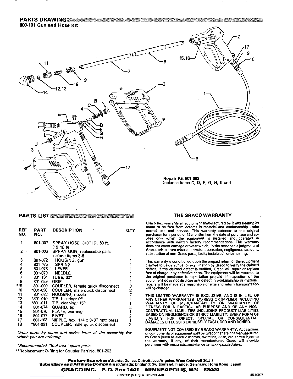
PARTS
LIST
THE
GRACO WARRANTY
REF
NO.
1
2
3
4
5
6
7
8
""9
10
11
13
12
14
15
16
17
18
PART DESCRIPTION
NO.
801-007 SPRAY HOSE,
3/8"
ID,
50
ft.
(15
rn)
lg
801-006 SPRAY GUN, replaceable parts
include
item$
3-6
801-072 . HOUSING, gun
801675
.
SPRING
801-078
~.
LEVER
801-079
.
NEEDLE
801-029 GRIP
801-134 TUBE,
32"
801-009 COUPLER, female quick disconnect
801-073 HOUSING. nozzle
'801-090
COUPLER, male quick disconnect
~~ ~ ~ ~ ~ ~~
*801-010 TIP, blasting;
Oo
'801-011 TIP, cleaning; 15O
801-074 GUARD,
tip
801-076 PLATE, warning
801477
RIVET
801-103 NIPPLE, hex; 1/4
x
3/8"
npt;
brass
~_,
'801-091
COUPLER. male ouick disconnect
QTY
1
2
2
1
1
2
1
2
2
1
Graco Inc. warrants a11 equipment manufactured by
it
and bearing
its
name to be free from defects in material and workmanship under
normal use and service. This warranly extends to the original
purchaserforaperiodof12monthsfromlhedateofpurchaseandap-
plies only when the equipment is installed and operated in
accordance with written factory recommendations, This warranly
does not cover damage or wear which,
in
the reasonable judgment
of
substitutionof
non-Gracoparts,faullyinstallationortampering.
Graco, arises from misuse, abrasion, corrosion, negligence, accident,
This warranty is conditioned upon the prepaid return
of
the equipment
claimed to be defective for examination by Graco to verify the claimed
defect. If the claimed defect is verified, Graco will repair or replace
free of charge, any defective parts. The equipment will be returned to
the original purchaser transportation prepaid.
if
inspection of the
equipment does not disclose any defect
in
workmanship or material,
will becharged.
repaim will be made at
a
reasonable charge and return transportation
. ~~
~.~
~~
~~~
-
EQUIPMENT NOT COVERED
BY
GRACO
WARRANN.
Accessories
Order parts
by
name and series lerter
of.
the assembly for
which
you
are
ordering.
or
components
of
equipment sold by Graco that are
not
manufactured
by Graco (such as electric motors, switches, hose, etc.) are subject
to
*Recommended
"tool
box" spare parts.
the warranty,
if
any, of their manufacturer. Graco will provide
purchaser with reasonable assistancein making such claims.
**Replacement
0-Ring
for Coupler Part'No. 801-202
FaGtDlyeranches:Atianta,
Dallas, Detroit. LOSAngeles. West Caldwell
IN.J.1
Subsidla~andA*iliateCompanies:Canada:
England; Switzerland: France; Germany: Hong
Kong:
Japan
 Loading...