

Page 1
INSTRUCTIONS-PARTS
This
manual
WARNINGS
READ
AND RETAIN
conteins
and
IMPORTANT
INSTRUCTIONS
FOR
REFERENCE
LIST
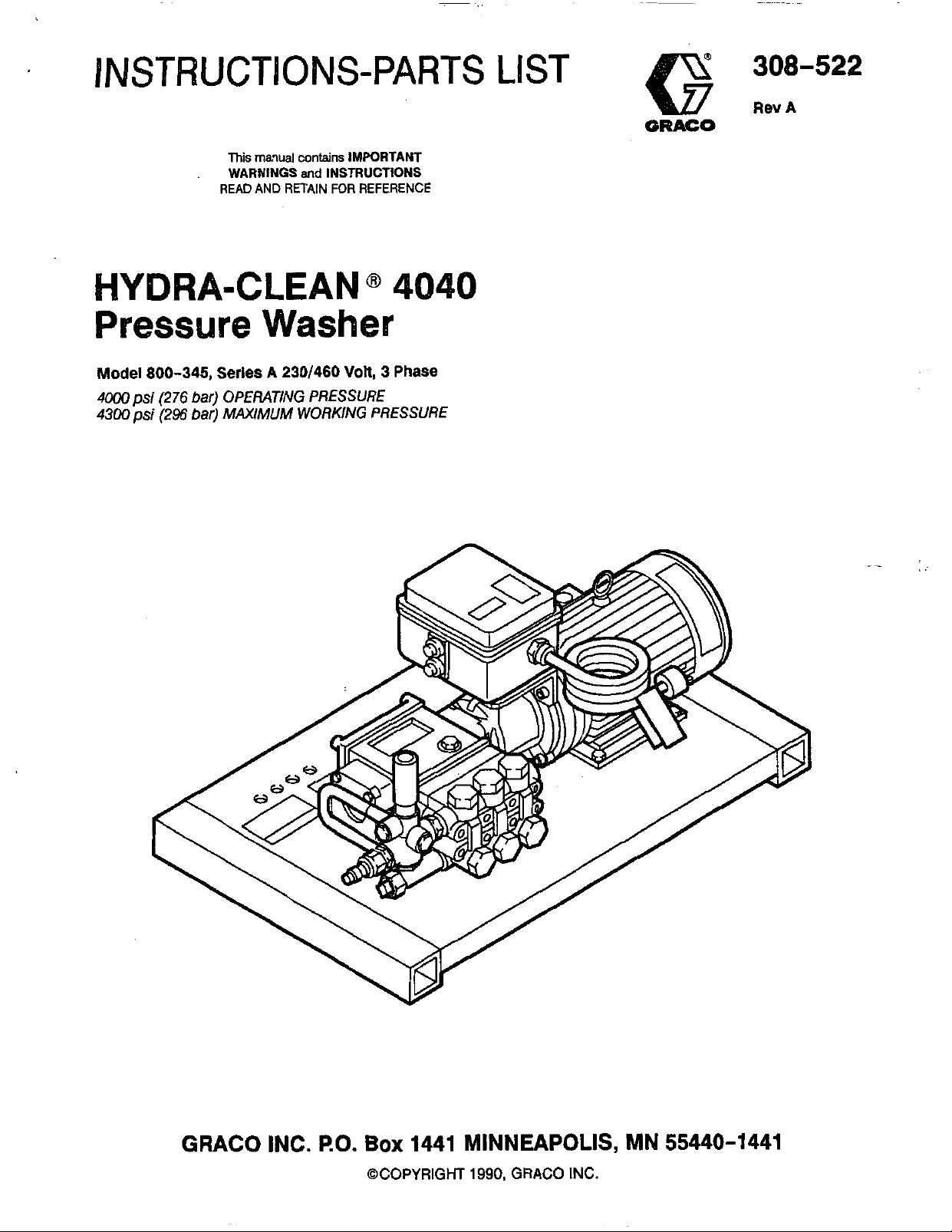
HYDRA-CLEAN
@
4040
Pressure Washer
Model
4ooo
4300psi
800-345,
psi
(276
(296
Series
bar)
bar)
A
230/460
OPERATING PRESSURE
MAXIMUM
WORKING PRESSURE
Volt,
3
Phase
GRACO INC.
RO.
Box
1441 MINNEAPOLIS, MN 55440-1441
@COPYRIGHT
1990,
GRACO
INC.
Page 2
~
BNG
Read
HIGH
FOR
and
PRESSURE SPRAY CAM CAUSE SERIOUS INJURY.
PROFESSIONAL
understand
all
USE
ONLY.
instruction
FLUID INJECTION HAZARD
General
This pressure washer generates very
pressure. Spray from the gun, leaks or ruptured
components can inject fluid through your skin and into
your body and cause extremely serious bodily injury
including theneedforamputation. Als0,fluid injectedor
splashed into the eyes or on the skin can cause serious
damage.
NNER
part of the body.
spray tip.
ALWAYS
cleaning or servicing any part of the sprayer.
NNER
body.
Be sure equipment safety devices are operating
properly before each use.
Safety
high
fluid
point the spray gun or wand at anyone
NNER
follow the Pressure Rellef Procedure, before
try
to
stop or deflect leaks with your hand or
put hand or fingers over the
of
at any
OBSERWE
manuals
Pressure
To
reduce the risk
injection and splashing in the eyes or on the skin,
always follow this procedure whenever you stop
spraying for more than
and before checking or repairing any part of the system.
1.
Engage the trigger safety latch.
2.
Turn the sprayer
3.
Disconnect the electrical supply.
4.
Shut
5.
Disengage the trigger safety latch and trigger the
gun
safety latch again.
6.
Before long-term (overnight) storage, disconnect
the water supply and disconnect the electricity.
ALL WARNINGS.
before
off
to
operating
Relief Procedure
of
serious bodily Injury, including fluid
10
off.
the water supply.
relieve pressure, and then engage the trigger
equipment.
minutes, when shutting down,
..
.
..
..
Medical
If
any
EMERGENCY MEDICALTREATMENTATONCE.
NOTTREAT AS A SIMPLE CUT. Tell the doctor exactly
what fluid was injected.
NOTE TO PHYSICIAN: lnjection
traumatic
surglcally
treatment
concern with some exotic coatings injected
directw into the bloodstream. Consultation with a
plastic surgeon or reconstructive hand surgeon
may be advisable.
Treatment
fluid
appears
injufg
as soon
to
to
penetrate your skin, get
in
the skin
It
Is
Important
as
research toxicip Toxicily
to
posslble.
treat the
Do
not delay
is
Injury
is
DO
a
a
Spray
Be sure all gun safety devices are operating properly
before each
the gun; this can cause a malfunction and result in
serious bodily
SAFm LATCH:
moment, always set the gun safety latch in the engaged
0r"safe" position, making the guninoperative. Failure
properly
triggering of the gun.
SPRAY
cleaning
while spraying, engage the gun safety latch
immediately.
Procedure and then remove the spray tip
Gun
Safety Devices
use.
Do not remove or modify any part of
injury.
Whenever you stop spraying for a
set
the safety latch can result in accidental
TIP
SAFm
or
changing spray
ALWAYS
Use extreme caution
tips.
If
a
spray tip
follow the Pressure Relief
to
to
when
clogs
clean it.
2
308-522
Page 3
This product must be grounded. If it should malfunction
or break down, grounding provides a path
resistance for electric cunent
to
reduce the risk of
of
least
electric shock. This equipment is equipped with a cord
having an equipment-grounding conductor and a
grounding plug. The plug must be plugged Into an
appropriate outlet that is properly installed and
grounded
in
accordance with all local codes
and
ordinances.
DANGER
Improper connection of the equipmentgrounding conductor can result in the risk of
electrocution. Check with a qualified electrician
or service person
whether the outlet is properly grounded. Do not
modify the plug provided with the product
will not
fit
the outlet, have a proper outlet
installed by a qualified electrician.
if
you are
in
doubt as
-
to
if it
GROUND
To
comply with the National Electrical Code (NFPA
and
to
electric shock, connect this pressure washer
FAULT
CIRCUIT INTERRUPTER PROTECTION
70)
provide additional protection from the risk of
to
a
EXTENSION CORDS
Use only 4-wire extension cords that have 4-prong
grounding-type plugs and 4-pole cord connectors that
accept the plug from the product. Use only extension
cords that are intended for outdoor
use.
These
extension cords are identified by a marking,
"Acceptable for use with outdoor appliances; store
use."
indook while not in
having an electrical rating not
Use only.extension cords
less
than the rating of the
product. Do not use damaged extension cords.
Examine extension cord before using and replace
Do
damaged.
EQUIPMENT MISUSE
not abuse extension cord and do not yank
HAZARD
if
General Safety
Any misuse of the pressure washer or accessories,
such as overpressurizing, modifying parts, using
incompatible chemicals and fluids, or using worn or
and
result in
repair or
to
damaged parts, can cause them
rupture and
fluid injection, splashing in the eyes or on the skin, or
other serious bodily injury, fire, -explosion or property
damage.
NNER
so
CHECK
alter or modify any part ofthis equipment; doing
could cause it
all
to
malfunction.
spray equipment regularly
replace worn or damaged park immediately.
ALWAYS
clothing.
wear protective eyewear and appropriate
If
using a chemical injector, read and follow
the chemical manufacturer's literature for
recommendations on additional protective equipment,
such as a respirator.
receptacle that is protected by a ground-fault
circuit-intempter (GFCI).
..
,
to
or pull on any cord
'
heat and sharp edges. Always disconnect the extension
disconnect. Keep cord awayfrom
cord from the receptacle before disconnecting the
Droduct from the extension cord.
1-
WARNING
-1
To reduce the risk of electrocution, keep all
connections dry and
off
the ground. Do not
touch plug with wet hands.
System Pressure
This sprayer can develop high operating pressure.
sure that all spray equipment and accessories are rated
to
withstand the maximum working pressure of this
sprayer.
DO
NOT
exceed the maximum working
pressure of any component or accessory used in the
system.
Be
Chemical Compatibility
BE
SURE
injector are compatible with the wetted parts of the
hose,
(inside back
manufacturer's literature before using any chemical in
this pressure washer.
that all chemicals used in the chemical
gun, wand and tip, as given in the Technical Data
cover).
Always read the chemical
"
308-522
3
Page 4

HOSE
SAFETY
High
pressure fluid
If
the hose develops a leak, split or rupture due
kind
of
wear, damage or misuse, the high pressure
spray emitted from it can cause a fluid injection injury or
other serious bodily injury or property damage.
ALL FLUID HOSES MUST HAVE STRAIN RELIEFS ON
BOTH ENDS.
from kinks or bends at or close
can result in hose rupture.
TlGHTEN
'use. High pressure fluid can dislodge a loose coupling
or allow high pressure spray
coupling.
all fluid connections securely before each
MOVING
Moving parts can pinch or amputate fingers or other
body parts.
or operating the pressure washer.
NNER
and interlocks installed and functioning. Follow the
KEEP
operate the pressure washer without all guards
in
the hoses can be very dangerous.
to
The strain reliefs help protect the hose
to
the coupling, which
to
be emitted from the
PARTS
HAZARD
CLEAR of moving parts when starting
any
TERMS
NNER
entire hose for
damage or movement of the hose couplings. If any of
these condRions exist, replace the hose immediately.
DO
with tape or any other device.
contain the high pressure fluid.
HANDLEAND
on hoses to move the pressure washer.
chemicals which are not compatible wlth the inner
and cover of the hose.
temperatwes above
(-400
Pressure Rellet Procedure
servicing the pressure washer
high pressure fluid from the gun.
use a damaged hose. Before each
cuts,
leaks, abrasion,
NOT
try
to
recouple high pressure hose or mend it
A
repaired hose cannot
ROUTEHOSES CAREFULLY
DO
NOT
expose Graco hose to
2M)"
F
(93'
G)
C).
before checking or
to
prevent discharging
bulging
Do
M
below
use,
cover,
Do
not pull
not use
-40'
check
or
tube
F
WARNING
conditions that could cause bodily injury.
CAUTION
that could cause damage
or
DANGER
Alerts user
Alerts user
to
avoid or correct conditions
to
the equipment.
to
avoid or correct
NOTE
Identifies helpful procedures and information.
IMPORTANT
United States Government safety standards have been adopted under the Occupational Safety and Health Act. These
standards-particularly the General Standards, Part 1910, and the Construction Standards, Part 1926-should be
consulted.
4
308-522
Page 5
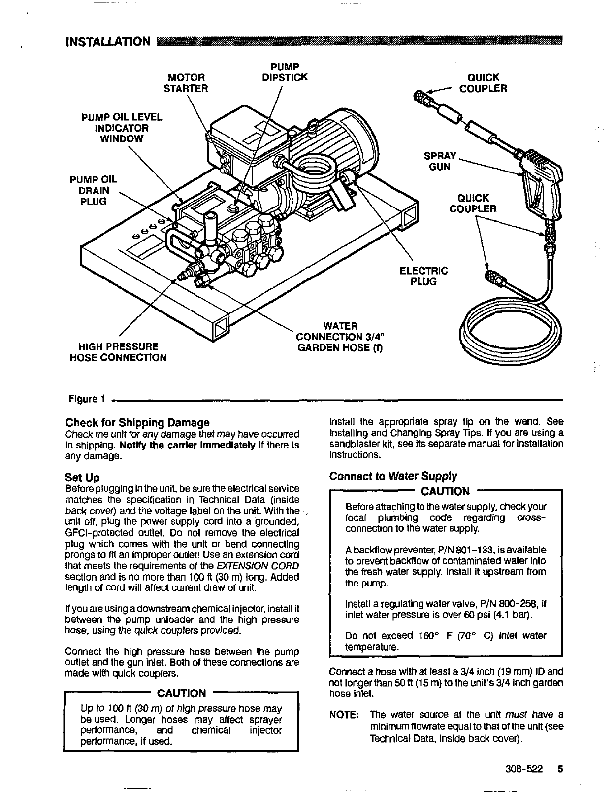
INSTALLATION
PUMP OIL LEVEL
INDICATOR
PUMP
MOTOR DIPSTICK QUICK
CONNECTION
GARDEN
Figure
Check
Check the unit for any damage that may have occurred
in shipping. Not@ the carrier Immediately
any damage.
1
for
Shipping Damage
if
there is
Set Up
Before plugging in the unit, be sure the electrical service
matches the specification
back cover) and the voltage label on the unit. With the
unit
off,
plug the power supply cord into a grounded,
GFCi-protected
plug which comes with the unit or bend connecting
prongs to fit an improper outlet! Use an extension cord
that meets the requirements
section and is no more than
length of cord will affect current draw of unit.
If you are using a downstream chemical injector, install it
between the pump unloader and the high pressure
hose, using the quick couplers provided.
Connect the high pressure hose between the pump
outlet and the gun inlet. Both of these connections
made with quick couplers.
outlet.
in
Technical Data (inside
Do not remove the electrical
of
the
100
fl(30
EXTENS/ON
m) long. Added
CORD
are
.
CAUTION
Up
lo 100
beused. Longer hoses may affect sprayer
performance, if used.
ft
(30
m)
and
of
high
pressure hose may
-1
chemical injector
314"
HOSE
Install the appropriate spray tip on the wand. See
lnstaliing and Changing Spray
sandblaster kit, see its separate manual for installation
instructions.
(9
Tips.
If
you
are
Connect to Water Supply
CAUTION
,
Before attaching to the water supply, check your
local plumbing code regarding
connection
A
backilow preventer,
to
prevent backflow of contaminated water Into
the fresh water supply. Install it upstream from
the pump.
Install a regulating water valve,
inlet water pressure is over
Do
not exceed
temperature.
Connect a hose with at least a
not longer than
hose inlet.
NOTE
to
the water supply.
P/N
801
-1
33,
is available
P/N
800-258,
€0
psi
(4.1
bar).
160°
F
(70"
C) inlet water
3/4
inch
(19
mm) ID
50
fl(15
m)
to
the unit's
me water source at the unit
minimum flowrate equal
Technical Data, inside back cover).
314
Inch garden
must
to
that of the unit (see
using a
cross-
if
and
have a
308-522 5
Page 6
STARTUP
Always
is started safely and properly.
1.
2.
use
this start up procedure
Check the oil level.
Pump: Add SAE
as necessary.
Tum on
the
XI
water supply.
to
ensure that the unit
or
30
weight non-detergent oil
CAUTION
Never
run
the
unit dry. Costly damage
pump will result. Always be sure the water
supply
operating.
I
3.
Trigger the gun until water sprays from the tip
indicating that
4.
Plug the electrical cord into proper, grounded,
GFCI-protected
5.
ALWAYS
whenever you stop spraying,
reduce the risk of fluid injection or splashing in the
eyes or on the skin
accidentally.
is
completely tumed on before
the
air is purged from the system.
outlet.
engage the gun’s trigger safety latch
even
if
the gun is bumped or triggered
to
for a moment
the
to
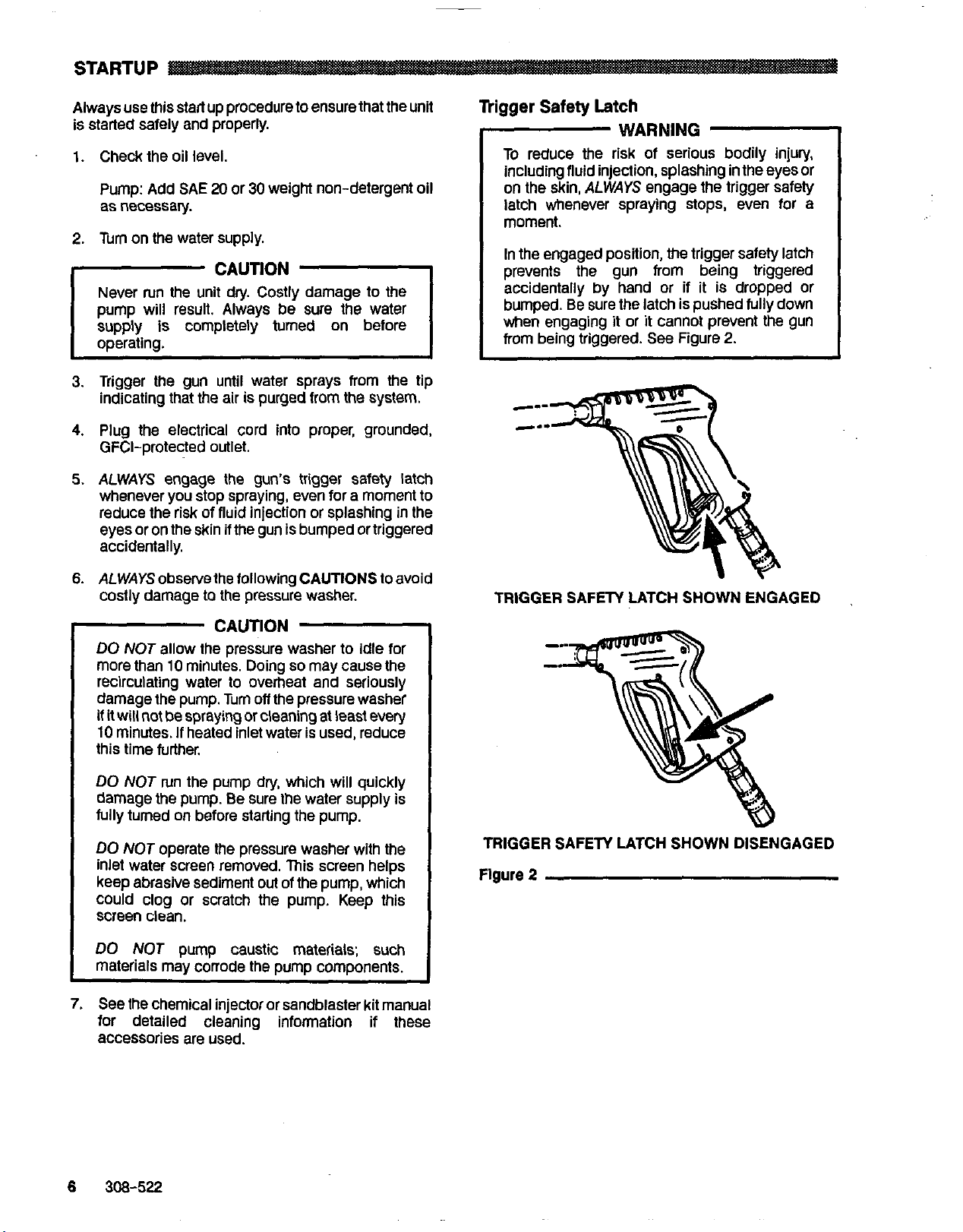
Trigger
Safety
Latch
WARNING
To reduce
including fluid injection, splashing in the eyes or
on the skin,
latch whenever spraying
moment.
In
the
prevents the gun from being triggered
accidentally by hand or if it is dropped or
bumped.
when engaging it or it cannot prevent the gun
from being triggered.
the
risk of serious bodily injury,
ALWAYS
engaged position, the trigger safety latch
Be
sure the latch is pushed fully down
engage the trigger safety
See
stops,
Figure
even for a
2.
6.
ALWAYS
costly damage
observe
to
the following CAUTIONS to avoid
the pressure washer.
CAUTION
DO
NOT
allow the pressure washer
more than
recircuiating water
damage the pump. Tum
if it will not
10
minutes.
this time further.
DO
damage the pump.
fully tumed on before starting the pump.
DO
inlet water screen removed. This screen helps
keep abrasive sediment
could clog or scratch the pump, Keep this
screen clean.
DO
materials may corrode the pump components.
7.
See
for detailed cleaning information if these
accessories are used.
10
minutes. Doing
lo
De
spraying or cleaning at least every
If
heated inlet water is used, reduce
NOT
run the pump dry, which will quickly
Be
NOT
operate the pressure washer with the
NOT
the chemical injector or sandblaster kit manual
pump caustic materiais; such
so
overheat and seriously
off
the pressure washer
sure the water supply is
out
of the pump, which
to
idle for
may cause
the
TRIGGER SAFETY LATCH SHOWN ENGAGED
TRIGGER SAFETY LATCH
Figure
2
SHOWN
DISENGAGED
6
308-522
Page 7

Installing
and
Changing Spray lips
WARNING
To
reduce the risk of serious bodily injury,
including fluid injection
or onto the skin, use extreme caution when
changing spray tips.
procedure below.
1.
Follow
2.
Point the gun and wand away
anyone
3.
Without holding your hand over the spray tip
pull back the quick coupler ring
and then release the ring.
4.
Be
again.
5.
Tip holding holes are provided on the chassis.
the
Pressure
else.
sure the tip is secure before starting to spray
or
splashing in the eyes
ALWAYS
Rellet
Procedure.
follow the
from
(B),
remove the tip
See
Figure
yourself and
(A),
3.
CAUTION
To
avoid blowing the O-ring
coupler, due to the high pressure
never operate
securely mounted in the quick coupler.
Figure
3
the
pressure washer without a tip
out
in
of
the
the
qulck
system,
308-522
7
Page 8

SHUTDOWN, FLUSHING
AND STORAGE
MAINTENANCE
WARNING
Pressure Rellef Procedure
To reduce the risk of serious bodily injury,
including fluid injection and splashing in the
eyes, or on the skin, always follow this
procedure whenever you stop spraying for more
10
than
before checking or repairing any part of the
system.
1.
2.
3.
4.
5.
6.
1.
If
the pressure washer will be exposed
temperatures, drain all water out of the pump. If it
must be stored in freezing temperatures, flush the
unit with a
pressure. Flush the pressure washer before using
again
minutes, when shutting down, and
Engage the trigger safety latch.
Tum the sprayer
Disconnect the electrical supply.
Shut
off
the water supply.
Disengage the trigger safety latch and
trigger the gun to relieve pressure, and then
engage the trigger safety latch again.
Before long-term (overnight) storage,
disconnect
disconnect the electricity.
to
remove the anti-freeze.
off.
the
water supply and
50%
anti-freeze solution. Relieve
to
freezing
Observing regular maintenance intervals helps ensure
that you get maximum performance and life from the
pressure washer.
There is a break-in period for the pump. Afler changing
the oil initially, the interval between required changes
longer.
WARNING
To reduce the risk
includingfluid injection, splashing in the eyes or
on
the
skin or injury from moving parts, always
follow the
interval
Daily Clean water inlet screen and
After first
hours of SAE
operation
500
Each
of operation or
6
months
it
Pressure Relief Procedure
50
hours Change pump oil.
of
What
to do
filter. Check pump oil level. Fill
as necessary.
Change pump break-in oil.
20
or
30
non-detergent oil.
-I
serious bodily injury,
Warning
30
non-detergent oil.
Use
SAE
Use
20
Is
or
I
NOTE:
An anti-freeze flush kit
to
available
make flushing easier.
P/N
CAUTION
If water does freeze in the pressure washer,
thaw it
DO
2.
After each
washer with a clean, damp cloth.
3.
Perform
maintenance chart.
in
a warm room before trying to start it.
NOT
pour hot water on or into the pump; it
use,
wipe all surfaces of the pressure
the appropriate maintenance.
802-327
See
the
is
E
308-522
Page 9

TROUBLESHOOTING CHART
To
reduce
injury
from
the
risk of serious bodily injury,
moving
parts,
always fallow
including
the
Pressure
WARNING
fluid
injection,
Relief
splashing
Procedure
in
the eyes
or
on
the
skin,
Warning before proceeding.
or
PROBLEM
DW
pressure and/or
ump runs rough
rater leakage from
nder pump manifolc
rater
in
pump
'eqequent
or
emature failure of
18
packings
lrong surging at the
let
and low pressurt
1
the
discharoe side
nit
will
nd
start
CAUSE
Wom or wrong size
tip.
Inlet filter clogged.
Wom packings, abrasives
in
water or
I
Replace with tip
SOWTION
of
proper size.
Clean. Check more frequently.
Checlc filter. Replace packings.
See
PUMP SERVICE.
natural wear.
rate
to
Inadequate water supply.
Coupling slippage.
or
dirty
Fouled
inlet or discharge valves.
Even a small particle can cause the valve
lo
stick.
Reslricted inlet.
Worn inlet or discharge valves.
Leakina hiah msure hose.
Wom packings.
Check water flow
Tighten or replace.
Clean Inlet and discharge valve assemblies. Check
filter.
Check
Replace
Reolace hlah mwre hose.
Install new packings.
garden
worn
hose. may
valves.
pump.
be
collapsed or
See
PUMP SERVICE.
kinked.
Humid air condensing inside crankcase. Change oil as specified in MAINTENANCE.
Wom packings.
Install new packings.
Install new oil seals.
Scored, damaged or worn plungers. Install new plungers.
fluid
being
Abrasive material in the
Inlet water temperature
too
Overpressurizing pump.
high.
pumped.
Install proper filtration on pump inlet plumbing.
Check water temperature; may
Do
not modify any factory-set adjustments.
EQUIPMENT MISUSE
Excessive pressure due
to
partially plugged or replace
tip.
See
PUMP SERVICE.
See
PUMP SERVICE. Oil seals leaking.
See
PUMP SERVICE.
not
exceed
HAZARD.
See
Installing and Changing Spra)
or damaged tip.
Pump running
long without spraying.
Never run pump more than
Do not
run
pump without water.
10
minutes without spraying
too
Running pump dry.
in
Foreign particles
the inlet or discharge
Clean or replace valves.
See
PUMP SERVICE.
valve or wom inlet and/or discharge valves.
Unit not plugged
Electrical service off/GFCI activated.
mermai overload has tripped.
in.
Check power cord.
Check fuse/circuit breaker. Check for proper
grounding.
Press
stop button on
the
motor starter.
160°F.
See
308-522
9
Page 10

PARTS
800-345
For wiring diagram, see page
DRAWING
Hvdra-Clean@
4040
Pressure Washer
14
~~~~~
10
308-522
Page 11

PARTS
800-345
LIST
Hydra-Clean@
4040
Pressure Washer
REF
NO.
1
2
3
4
5
6
7
8
9
10
11
12
13
14
15
16
17
18
19
20
21
22
23
24
25
27
28
29
30
31
32
33
34
PART
NO.
DESCRIPTION
QN
800-579 PUMP & MOTOR ASSEMBLY
(see
page 15)
803-554 BRACKET, Pump Support
801-382 CORD, Power 10/4
803-263 BRACKET. Starter.
left
159-239 NIPPLE, Hex 1/2 x 3/8
802-732 WASHER. Flat
802-731 WASHER: Lock
#6
#6
1
1
48
1
2
4
4
803-484 SCREW, Cap, pan hd. 4
803-517 LABEL, Keep From Freezing
800-427 UNLOADER,
4ooo
psi
1
1
800-450 HOSE ASSEMBLY, w/Quick
Couplers (includes 14, 18,
20)
1
801-009 QUICK COUPLER, Femaie 1/4
1
154-594 O-RING, (includes Quic 13L Coupler 1/4 1
801-568 QUICK COUPLER, Male 3/8
802-534 NIPPLE, Hex 1/2 NPSM
112 NPT
803-141 HOSE, Bvoass
X
2
1
1
803-395 LABEL, Model 4040 1
803-519 HOSE, High Pressure 3/8 x
50
ft 1
800-429 GUN &WAND ASSEMBLY
fincl. 12. 20. 28. 29. 34. 35) 1
803-157 QUiCK COUPLER, Femaie 318
(includes 21) 2
156-082 OkNG, Quicik Coupler 3/8 2
402-278 PLUG. Plastic
1
804-051 STRAiNEWFiLTER 1
801-110 ADAPTER, Garden Hose
801-1 11 NUT, Garden Hose
801-106
801-957
TEE. 112 1
SLERIE,
18”
1
1
1
801 -1 34 WAND, 32 1
803-262 BRACKET, Starter, right 1
800-441 CHASSiS 1
802-993 PLUG,-Locking 15 hp, 460 volt 1
803-186 LABEL, Cordset
803-351 GUN, Spray, SST
(See
1
Instruction Manual 308-51 1) 1
in
REF
NO.
35
36
37
38
39
40
41
42
43
44
45
46
47
48
49
50
51
52
53
54
55
56
57
58
59
60
61
62
63
64
PART
NO. DESCRIPTION
ON
156-849 NIPPLE, Hex 3/8
803-591 WASHER, Flat 1/2
802-784 WASHER, Lock 112 4
803-592 SCREW, Cap, hex hd.
1/2-13
X
1-1/2 4
801-012 GROMMET., Rubber
800-124 TIP ASSEMBLY,
(includes
45,
OOO4
60)
800-125 TIP ASSEMBLY, 1504
(includes
45,
61) 1
800-126 TIP ASSEMBLY, 2504
(includes
800-127 TIP ASSEMBLY.
~~~
45,
62) 1
4004
(includes 45,’63)~
801-WB DECAL. Graco G
Soi-Os0
QUICKCOUPLER,
Male 1/4 4
2
~
176-250 LABEL, Warning, chassis
176-981 LABEL, Warning. chassis
803-396 LABEL, WamingICavtion 1
100-527 WASHER, Flat 5/16
100-21 4
WASHER, Lock 5/16
100-188 NUT, Hex 5/16-18
2
2
2
803-007 LABEL, Caution, 230 volt,
3 phase
803-006 LABEL, Caution, 460 volt,
3 phase 152
801-226 CONNECTOR, Wire 4
801-382 CORD. Power 12/4
1
802-81
CORD’GRiP
804-043 SWITCH. Starter. 15
803-749 SWITCH: Starter: 15
hD
hp
230
460
8n
3
Volt
Volt
801-937 NUT. Lock. electrical 1
801-523
NIPPLE,
1i2 X 2
801-221 TERMINAL. Rina
801 -599 TIP, Spray
6004’
80-600 TIP SDrav 1504
801-661
TIP;
sprai, 2504
801-602 TIP SDrav 4004
801-304
TERMINAL, Ring
1
4
5
1
1
1
1
1
1
1
308-522
11
Page 12

I
53
Model 4040
Wirlng Diagram
230
Volt.
3
Phase
Model 4040
Wring Diagram
Volt,
3
460
Phase
12
308-522
Page 13

PARTS
DRAWING
800-579 Pump
and
Motor Assembly
PARTS
LIST
800-579 Pump
REF
NO.
10
11
1
2
3
4
5
6
7
8
9
PART
NO.
803-584
802-698
802-540
802-784
803-750
802-508
100-527
801 -559
802-783
802-794
803-552
and
Motor Assembly
DESCRIPTION
MOTOR,
COUPLER, 15 hp
15.0 hp TEFC, 3 phase
HOUSING
WASHER, Lock 1/2
SCREW, Cap, socket hd.
1/2-13
PUMP (see page 16)
WASHER, Lock 5/16
SCREW, Cap,
KM,
KM,
RING,
X
Motor
Pump
Adapter
3
hex
hd.
M8
x
30
QTY
1
1
1
4
4
1
4
4
1
1
1
308-522
13
Page 14

PARTS
803-508
DRAWING
Pump Assembly,
4000
psi
45
1
-/-
/
/-
14
308-522
Page 15

PARTS
803-508
LIST
Pump
Assembly,
4000
psi
REF
NO.
1
2
3
4
5
6
7
8
9
10
11
12
13
14
15
16
17
18
19
20
21
22
23
24
25
26
27
PART
.
.....
NO.
801 -647 MANIFOLD
~~ ~
DESCRIPTION
~~ ~~~
~-
801-468 SCRNV, Cap, hex hd.
801-469 WASHER. Lock
KIT 1
KIT 1
KIT
KIT 1
KIT 1
KIT 106
KIT
KIT
803-283
803-506
802-500
803-324
KIT 2
803-286
803-501
801 -475
803-1
803-287
803-288
802-794
803-289
803-503
803-291
803-292
O-RING
SEAT, Valve
1
PLATE, Valve
SPRING
GUIDE, Valve
O-RING
CAP
106
1
VALVE ASSEMBLY
SCREW, Cap, socket hd.
COVER, Crankcase
O-RING, Crankcase Cover
BEARING, Tapered Roller
SEAL, Oil
BUSHING, Piston
CRANKCASE
DIPSTICK
44
GASKET, Cover
CRANKSHAFT
RING, Retaining
KEY
PIN, Wrist
GUIDE, Piston
ROD,
Connecting
SCREW, Cap, socket hd.
QTY
1
8
8
8
1
2
2
1
1
1
1
1
6
1
3
3
3
5
REF PART
NO.
28
29
30
31
32
33
34
35
36
37
38
39
40
41
42
43
44
45
46
47
51
52
53
54
NO. DESCRIPTION
803-507 COVER, Crankcase
802-345 GAUGE, SigM
802-793 PLUG, Oil Drain
KIT 107 O-RING
803-294 SCREW, Cap,
socket
801-652 WASHER, Lock
KIT 107 WASHER, Flinger
801-490 PLUNGER, Ceramic
803-502 PLUNGER, Ceramic
KIT 107 RING, Backup
KIT 107 WASHER
KIT 107 SCREW, Piston
803-505 COVER, Crankcase
803-296 SHIM
KIT 3 SEAL, Oil
KIT 109
KIT 109
KIT 109
KIT 112
KIT 109
KIT 109
KIT
801 -482
801
-483
801 -484
801 -485
O-RING
RETAINER. Packing
PACKING
PACKING
RING, Head
RETAINER, Packing
RING, Long Life
109
PLUG, Hex
WASHER, Flat
PLUG, Hex
WASHER, Flat
hd.
QTY
1
1
1
6
6
3
3
1
2
1
1
1
1
Klt
No.
1
2
3
106
Repalr Kit
Part No.
801-472
Valve
801-473
Oil Seal Kit
802-511
Crankshaft
Seal
802-509
Valve Cap
4000
psi
Ret.
No.
4
5
Descrlption
O-RING
SEAT,
Valve
6 PLATE, Valve
7
8
16
41
9
10
SPRING
GUIDE, Valve
11
VALVEASSEMBLE
SEAL. Oil
SEAL,
O-RING
CAP
Oil
.
QW
6
6
6
6
6
6
3
2
6
6
Repalr Kit
Kk
Part
No.
No.
Plunger WASHER, Flinger
Plunger WASHER, Flinger
Repair RING, Backup
Repair RING, Backup
Retainer
Ref.
No.
Descrlptlon
Packing
QiY.
PACKING
RING. Head
It
II
112
803-512
I46 I RETAINER,
44
PACKING
I1
.
6
Packing
4ooo
psi
308-522
15
Page 16

PUMP
I
I
NOTE:
NOTE
SERVICE
To reduce the risk Of serious bodily injury,
including
on the skin, or injury from moving parts, always
follow the
before proceeding.
fluid
injection, splashing in the eyes or
Pressure
The following metric wrenches are needed:
M10,
M13 ani M30. ReDair kits are available. screw.
Refer
to
pump parts page for more details. For the best
results, use all parts in the kits.
There are
servicing the pump. P/N 800-298 is used
ease installation of packings. P/N 800-271
includes
in the removal of packing retainers.
Relief
WARN'NG
the individual repair sections and
two
the
items
Procedure
different
in
800-298 and
Warning
1
tool
kits
to
tools
Valves
NOTE
1.
2.
3.
4.
NOTE
For a
set
of six valves, order P/N 801 -472.
Remove the hex plug from the manifold using an
M30 wrench.
Examine the O-ring under the hex plug and replace
it if it is cut or distorted.
Remove the valve assembly from the cavity; the
assembly may come apart.
lnslall the newvalve. Install the O-ring and hex plug;
torque
to
75
Retorque the plug after 5 hours of operation.
.-
ft-lb (103 Nm).
the
aid in
to
aid
to
I
Servicing the Plungers
NOTE
1. Loosen the plunger retaining screw five
2. Remove the screw from the plunger and examine
3. Remove the plunger and flinger from the plunger
4.
5.
6.
NOTE:
Plunger repair kit, P/N 803-510 is available
replace retainers, O-rings, washers and
backup rings for three cylinders.
(19.5
'
to
is
available
Nm).
-
using an M10 wrench. Push the plunger towards the
to
crankcase
the O-ring, backup ring and copper bearindgasket
washer. Replace these parts,
803-510.
shaft. Clean, examine and replace parts as
necessary.
Inspect the plunger shaft for oil leakage from the
crankcase. If leaking is obvious, replace the oil
seals. Otherwise,
they cannot be reused.
replace the seals.
Lightly grease the oil seal,
and the flinger and replace them on the plunger
shaft. Then install the plunger.
Lightly grease the retaining screw and the outer end
of the plunger. Place the washer, O-ring and backup
ring around the screw and install the screw through
the plunger. Torque
If
vou plan
Sitvicing the V-backings.
separate the plunger and retaining
DO
to
to
replace the Packinas. refer
..
if
necessary, using kit
NOT
remove these seals as
An
oil seal kit
if
it is being replaced,
14.4
ft-lb
to
six tums,
-
to
to
Pumping Section
1. Remove the eight capscrews and lockwashers from
the manifold using an M13 wrench.
2. Carefully separate themanifold
NOTE:
3. Carefully examine each plunger
It
may be necessary
a
soft
mallei
with
Keep
the
manifold properly aligned with the
ceramic plungers when removing
damage to the plunger or seals.
cracking and replace as necessary.
to
from
the crankcase.
to
tap the manifold lightly
loosen.
to
avoid
for
any scoring or
7.
Lubricate the outside of each plunger. Slide the
manifold
damage the seals.
8. Install the capscrews and washers finger-tight.
Torque the screws
tightening pattem (Figure 4). Uneven tightening
may cause the manifold
Figure
4
onto
the crankcase, being careful not
to
21.7 ft-lb
I
(29
Nm) following the
to
bind or jam.
I
to
16
308-522
Page 17

Servicing the V-Packings
NOTE
1.
2.
3.
4.
There
are
two
lypes
of
packing kits: one is
pacltlngs only, the other includes the
packings, rings
Remove the manifold as outlined In the Pumping
Section.
Carelully pull the packing retainer from the
manifold. Examine the O-ring and replace
cut or damaged.
Remove the v-packing and head ring. Pull out the
intermediate retainer ring. Remove the second
v-packing and second head ring.
inspect all parts and replace as necessary.
and
retainers.
It
if it is
5.
Thoroughly clean the packing cavities and examine
for debris and damage.
6.
Lightly grease the packing cavities and then
replace the packings in the following order: head
ring, v-packing. intermediate ring, head ring,
v-packing and packing retainer with. the O-ring
installed In the retainer groove.
CAUTION
the
Install the parts in
the
correct direction. Improperly installed parts
will cause a malfunction.
7.
Reassemble ¶he manifold
the Plungers.
proper order and facing
as
instructed in Servicing
308-522
17
Page 18

~
ACCESSORIES
(Must
be
purchased separately)
DOWNSTREAM CHEMICAL INJECTOR KIT WATER SANDBLASTING KIT 800-120
800-649
For injecting harsh cleaning chemicals downstream
from the pump. Stainless steel construction.
For abrasive cleaning
Requires a spray tip
kit.
of
stubborn dirt and paint.
(801-600)
which
is not included
in
UPSTREAM CHEMICAL INJECTOR
KIT
800-257
For
injecting mild cleaning chemicals upstream into the
Pump.
BACKFLOW PREVENTOR 801-133 INLET PRESSURE REGULATOR 800-258
Prevent back-up
supply. Install upstream
TECHNiCAL
of
contaminated water into fresh Regulates inlet water pressure to
of
pump. maximum.
DATA
ANTI-FREEZE FLUSH
For flushing system with
to
transporting or storing pressure washer
KIT
802-327
50%
anti-freeze solution prior
freezing temperatures.
60
psi
in
below
(4
bar)
High
Pressure
Hase
Acrylonitrile
and
Buna-N cover and tube
Synthetic yam and
EPDM
Pressure Washer Anodized aluminum, Aluminum or Bronze alloys,
(including fittings)
Ceramic, Buna-N,
Conon
Phenolic.
Thermoplastic. Teflono, Carbon
303,304,
Steel,
Zinc
with
and
or
Brass,
Copper, Nylon-TefionQ composite.
316
Stainless
without
Yellow
Steel.
Polymide-12
Chromare
Plate
Page 19

THE GRACO WARRANTY
WARRANTY AND DISCLAIMERS
Gram warrants ail equipment manufachrred by
andwo~manshiponthedateofsaiebyanauthorizedGramdistnbutortotheonginalpurchaserforuse.
As purchaser's
dateofsale,repairorreplaceanypartoftheequipmentpmvendefscthe.Thiswarran~appliesonlywhen
the
equipment
recommendations.
This warranty does not cover. and Gram
tauily
by
negligence. accident, tampering, or substihltion
liableform~nction,damageorwearcausedbytheinmmpatibilitywithGramequipmentofsfruchrres,
accessories. equipment or materials not supplied by Graco. or the improper design, manufacture,
installation. operation or maintenance
Grm.
Thii
warranty is conditioned upon
examination by Gram
replace
transportation prepaid.
workmanship. repairs will
labor and transportation.
DISCLAIMERS AND LIMITATIONS
METERMSOFTHlSWARRANPlCONSTiTUTETHEPURCHASER'SSOLEANDEXCLUSlVEREMEDY
ANDAREINLlEUOFANYOTHERWARRANTIES(EXPRESSORIMPLIED),lNCLUDlNGWARRANTYOF
MERCHANTABILITY
NON-CONTRACTUALLIABILITIES.
STRICT LIABILITY:
DAMAGES
LIABILITY EXCEED THE AMOUNT OF THE PURCHASE PRICE.
WARRANTY MUST BE BROUGHT WITHIN THREE
sole
remedy for breach ofthis warranty, Graco will,
is
installed. operated
installation. misapplication. abrasion, corrosion, inadequate or Improper maintenance,
of
the
the
claimed defect.
defecthe
madeata reasonable charge. which charges may include thecosts
FORM OF UABiLlTY
parts.
of
INCLUDING PRODUCTLIABILITIES. BASEDON NEGLIGENCEOR
free
of
OR
charge
EVERY
LOSS
to
verify
any
If
inspection
be
OR
WARRANTY
IS
EXPRESSLY EXCLUDED AND DENIED. IN NO CASE SHALL GRACOS
fi
and bearing its name to
and
maintained
shall
not
be
liable for, any malfunction. damage or
of
non-Graco component parts Nor shall Graco
sfruotures. accessories. equipmentor materials not supplied by
prepaid return
the equipment does not disclose any defect in material or
OF
If
The equipment will be returned
FITNESS FOR A PARTICULAR PURPOSE, AND
me
FOR
(3)
in
of
the
equipment claimed
claimed defect is verified. Graco will repair or
DIRECT SPECIAL
YEARS OF THE DATE OF SALE.
be
frea
from defects
for
a period
of
twenty four months
accordancB with Gram's written
to
to
the
in
material
wear
caused
be
defective for
original purchaser
of
parts.
OF
OR
CONSEQUENTIAL
ANY
ACTION FOR BREACH
from
be
ANY
OF
EQUIPMENT NOT COVERED
BY
GRACO WARRANTY
GRACOMAKESN0WARRANPl.ANDDiSCLAlMSALLIMPLIEDWARRANTIESDFMERCHANTABlLlTY
AND FITNESS FOR
MATERIALS
A
OR
COMPONENTS
PARTICULAR PURPOSE, WITH RESPECT TO ACCESSORIES, EQUIPMENT
SOLD
BUT
NOT MANUFACTURED BY GRACO. These
items
sold, but
notmanufacturedbyGraw(suchaselectricmotor,switches,hose,etc.)aresubjecttothewarranty,ifany.
of
their manufacturer. Graco will provide purchaser with reasonable assistance in making any claim
breach
of
these warranties.
for
IMPORTANT PHONE NUMBERS
TO PLACE AN ORDER,
distributor
FOR
application
Subsldlary and Affiliate Companies:
closest
TECHNICAL ASSISTANCE,
of
Graw
Factory Branches:
GRACO INC.
wntacd
to
you:
1-800-328-021 1
equipment:
Atlanta, Chicago. Dallas,
Canada; England; Swiizeriand; France; Germany; Hong Kong:
PO.
BOX
PRINTED IN U.S.A.
your
Graw
distributor,
Toll
Free
service repair information
1-800-543-0339
Delmi.
Toll
Free
Los
or
call
this
or
assistance
Angeles. West
number to
Caldwell
identify
regarding
(N.J.)
1441 MINNEAPOLIS, MN 55440-1441
308-522
1/91
the
the
Japan:
Korea
 Loading...