

Graco Inc Hydra-Clean 308-535, Hydra-Clean 2510, Hydra-Clean 800-901, Hydra-Clean 3009, Hydra-Clean 800-900 User Manual
Page 1
INSTRUCTIONS-PARTS
This
manual
wntains
WARNINGS
READ AND RETAIN
and
IMPORTANT
INSTRUCTIONS
FOR
REFERENCE
LIST
CDRACO
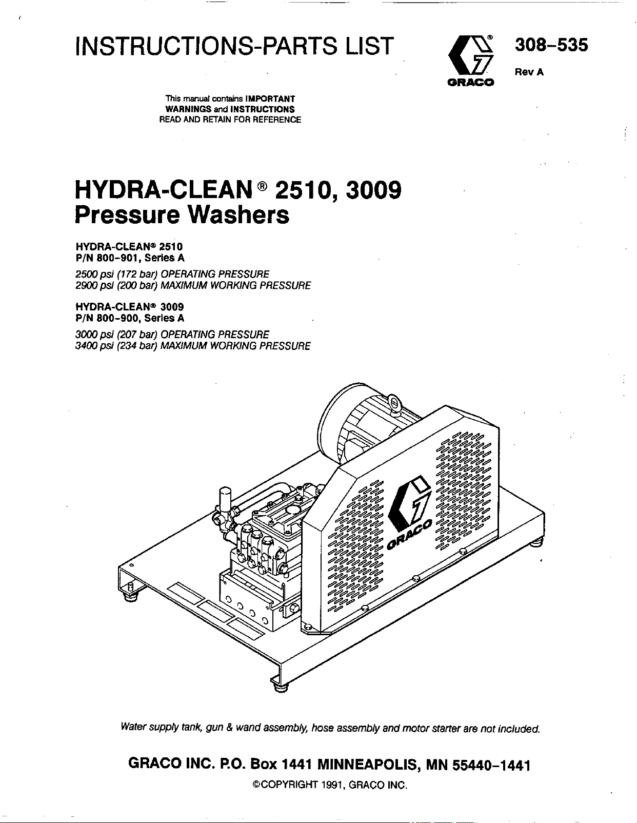
HYDRA-CLEAN
@
251
Pressure Washers
HYDRA-CLEAN"
P/N
800-901,
2500psi
2900
HYDRA-CLEAN"
P/N
3000
3400
(172
psi
(200 bar) MAXIMUM WORKING PRESSURE
800-900,
psi
(207
psi
(234 bar) MAXIMUM WORKING PRESSURE
2510
Series A
bar) OPERATING PRESSURE
3009
Series
bar) OPERATING PRESSURE
A
0,3009
Water
supply
tank, gun & wand assembM, hose assembly and motor starter are not included.
GRACO INC.
RO.
Box
1441 MINNEAPOLIS, MN 55440-1441
@COPYRIGHT
1991.
GRACO
INC.
Page 2
~A~~~~~
HIGH PRESSURE SPRAY CAN CAUSE SERIOUS INJURY.
FOR
PROFESSIONAL
Read and understand all instruction manuals before operating equipment.
USE
ONLY.
OBSERVE
ALL WARNINGS.
FLUlD
1NJECTlON
HAZARD
General Safety
This pressure washer generates very high fluid
pressure. Spray from the gun, leaks or tuptured
components can inject fluid through your skin and into
your body and cause extremely
including the need for amputation. Also, fluid injected or
splashed into the eyes or on the skin can
damage.
NNER
part of the body.
spray tip.
ALWAYS
cleaning or servicing any part of the sprayer.
NNER
body.
Be sure equipment safety devices are operating
properly before each
point the spray gun or wand at anyone or at any
NNER
follow the
try
to
stop or deflect leaks with your hand or
put
Pressure Relief Procedure,
use.
serious
hand or fingers over the
bodily injury
cause
serious
before
Medical Treatment
If
any fluid appears to penetrate your skin, get
EMERGENCY MEDICALTREATMENTATONCE.
NOT TREAT AS A SIMPLE CUT.
what fluid was injected.
Tell
the
doctor exactly
DO
Pressure Relief Procedure
To
reduce the risk of serious bodily injury, including fluid
injection and splashing
always follow this procedure whenever you stop
spraying for more than
and before checking or repairing any part of the system.
1.
Engage the trigger safety latch.
2.
Thm
the sprayer
3.
Disconnect the electrical supply.
4.
Shut
off
the water supply.
5.
Disengage the trigger safety latch and trigger the
gun to relieve pressure, and then engage the trigger
safety latch again.
6.
Before long-term (ovemighi) storage, disconnect
the water supply and disconnect the electricity.
in
the eyes or on the skin,
10
minutes, when shutting down,
off.
Spray Gun Safety Devices
Be
sure
all gun safety devices are operating properly
use.
before each
the gun; this can cause a malfunction and result in
serious bodily injury.
Do not remove or modity any part of
NOTE
traumatic
surgically as
treatment
concern
direct& into
plastic
may be advisable.
TO
PHYSICIAN
injug It
soon
to
research toxiciv. Toxicify
with
.some
the
surgeon
bloodstream. Consultation
or
injection
Is
Important to
as possible.
exotic- coatings injected
reconstructive
in
the
treat the
Do
not delay
hand
skin
is
a
InJury
is
a
wirb
a
surgeon
SAFEIY
moment, always set the gun safety latch in the engaged
or"safe" position, making thegun inoperative. Failureto
properly
triggering of the gun.
SPRAY
cleaning or changing spray tips. If a spray tip clogs
while spraying, engage the gun safety latch
immediately.
Procedure
LATCH:
set
TIP
Whenever you stop spraying for a
the safety latch can result in accidental
SAFm.
ALWAYS
and then remove the spray tip to clean it.
Use
extreme caution when
follow the
Pressure
Relief
2
308-535
Page 3
GROUNDING INSTRUCTIONS
This product must be grounded. If it should malfunction
or break down, grounding provides a path of least
resistance for electric current to reduce the risk of
electric shock. This equipment is equipped with a cord
having an equipment-grounding conductor and a
The
grounding plug.
appropriate outlet that is properly installed and
&dunbed in accordance wiih
ordinances.
plug must be plugged into an
all
local codes and
Improper connection of the equipment- grounding
conductor can result in the risk of electrocution.
Check with a qualified electrician or service
GROUND FAULT CIRCUIT INTERRUPTER PROTECTION
To
comply with the National Electrical Code
and to provide additional protection from the risk of
electric shock, connect this pressure washer to a circuit
that is protected by a ground-fault circuit-interrupter
(GFCI).
(NFPA
70)
EQUIPMENT MISUSE HAZARD
General Safety
Any misuse of the pressure washer or accessories,
such as overpressurizing, modifying parts, using
incompatible chemicals and fluids, or using worn or
damaged parts, can cause them to rupture and result in
fluid injection, splashing in the eyes or on the skin, or
other serious bodily injury, fire, explosion or property
damage.
System Pressure
This sprayer can develop high operating pressure. Be
sure that all spray equipment and accessories are rated
to.withstand the maximum working pressure of this
sprayer.
pressure of any component or accessory used
system.
DO
Chemical Compatibility
NNER
so
CHECK
replace worn or damaged parts immediately.
ALWAYS
clothing.
the chemical manufacturer's literature for
recommendations
such as a respirator.
alter or modify any part of this equipment; doing
could cause it to malfunction.
all
spray equipment regularly and repair or
wear protective eyewear and appropriate
If
using a chemical injector, read and follow
on
additional protective equipment,
BE
SURE
injector are compatible with the wetted parts
hose, gun, wand and tip, as given in the Technical Data
(inside back cover). Always read the chemical
manufacturer's literature before using any chemical in
this pressure washer.
DANGER
NOT
exceed the maximum working
that all chemicals
-1
used
in
the chemical
in
of
the
the
308-535
3
Page 4
HOSE
SAFETY
High pressure fluid in the hoses can be very dangerous.
If
the hose develops a leak, split or rupture due
to
any
kind of wear, damage or misuse, the high pressure
spray emitted from it can cause a fluid injection injury or
other
serious
bodily injury or property damage.
NNER
entire hose for cuts, leaks, abrasion, bulging cover, or
damage or movement of the hose couplings.
these conditions exist, replace the hose immediately.
DO
use a damaged hose. Before each use, check
NOT
try
with tape or any other device. A repaired hose cannot
ALL
FLUID
BOTH
from kinks or bends at or close
can result in hose rupture.
HOSES
ENDS.
MUST
HAVE
STRAIN'REUEFS
ON
The strain reliefs help protect the hose
to
the coupling, which
contain the high pressure fluid.
HANDLEAND
on hoses
chemicals which are not compatible with the inner tube
TlGHTfN
use. High pressure fluid can dislodge a
or allow high pressure spray
all fluid connections securely before each
loose
coupling
to
be emitted from the
and cover
temperatures above
(-400
C).
coupling.
MOVING
Moving parts can pinch
body parts.
PARTS
KEEP
CLEAR
HAZARD
or
amputate fingers or other
of moving
parts
when starting
..
Pressure Rellef Procedure before checking
servicing the pressure washer
or operating the pressure washer. high pressure fluid from the gun.
NNER
operate
the
pressure washer without all guards
and interlocks installed and functioning. Follow the
TERMS
to
recouple high pressure hose or mend it
ROUTEHOSES CAREFULLY
to
move the pressure washer.
of
the hose.
DO
NOT
expose Graco hose
DO
Do
200" F (93O C) or below
to
prevent discharging
,
.
.
If
any of
not pull
not use
to
-40'
or
F
WARNING
or
DANGER
Alerts user
to
avoid or correct
NOTE
Identifies helpful procedures and information.
conditions that could cause bodily injury.
CAUTION
that could cause damage
Alerts user
to
avoid or correct conditions
to
the equipment.
IMPORTANT
United States Government safety standards have been adopted under the Occupational Safety and Health Act. These
standards-particularly the General Standards, Part 1910, and the Construction Standards. Part 1926-should be
consulted.
4
308-535
Page 5
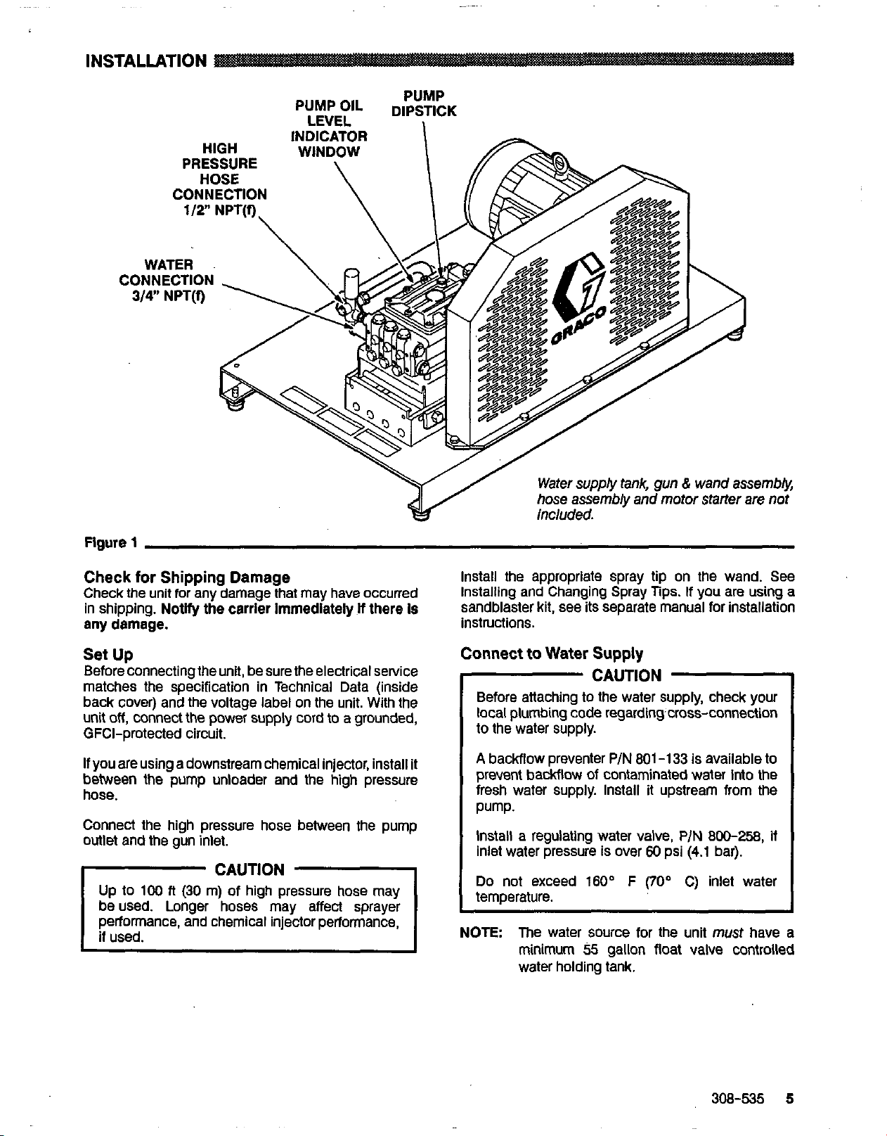
INSTALLATION
OIL DIPSTICK
LEVEL
PUMP
Figure
Check
Check the unit for any damage that may have occurred
in shipping.
any damage.
Set
Before connecting the unit, be sure the electrical setvice
matches the specification in Technical Data (inside
back cover) and the voltage label on the unit.
unit
GFCI-protected circuit.
If
between the pump unloader and
hose.
Connect the high pressure hose between the pump
outlet and me gun inlet.
1
for
Shipping Damage
Notify
the carrier Immediately
If
there
Is
Up
With
the
off,
connect the power supply cord to a grounded,
you are using a downstream chemical injector, install it
the
high pressure
Up
to
100
fi
(30
m)
of high pressure hose may
beused. Longer hoses may affect sprayer
performance, and chemical injector performance,
Install the appropriate spray tip on the wand. See
Installing and Changing Spray Tips.
sandblaster kit, see
instructions.
Connect
NOTE:
If
you are using a
its
separate manual for installation
to
Water
Before attaching to the water supply, check your
local plumbing code regardingcross-connection
to the water supply.
A
backflow preventer
prevent backflow
fresh water supply. Install
Pump.
Install a regulating water valve,
inlet water pressure is over
Do not exceed
temperature.
The water source for the unit
minimum
water holding tank.
Supply
CAUTION
P/N
801-133
of
contaminated water
it
60
160'
F
(70'
55
gallon float valve controlled
is
available to
into
upstream from the
P/N
800-258,
psi
(4.1
bar).
C) inlet water
must
the
if
have
a
308-535
5
Page 6
Use this procedure whenever starting the pressure
to
washer
and starting is done safely.
1.
2.
Tum on the water supply.
help insure that the unit is ready
Check the oil level.
Pump: Add SAE
as necessary.
20
or
30
weight non-detergent oil
to
operate
CAUTION
Never run the unit dry. Costly damage
pump will result. Always be sure the water
supply is completely tumed on before
operating.
3.
Trigger the gun until water sprays tom the tip
indicating that the air is purged tom the system.
4.
Start the unit.
5.
ALWAYS
whenever you stop spraying, even for a moment
reduce the risk of fluid injection or splashing in the
eyes or on the skin
accidentally.
engage the gun’s trigger safety latch
if
the gun is bumped or triggered
to
the
to
6.
ALWAYS
costly damage
observe the following
to
the pressure washer.
CAUTIONS
CAUTION
DO
NOT
allow the pressure washer
more than
recirculating water
damage the pump.
if it will not be spraying or cleaning at least every
10
minutes.
this time further.
DO
damage the pump. Be sure the water supply is
fully tumed on before starting the pump.
DO
materials may corrode the pump components.
7.
See the chemical injector or sandblaster
for detailed cleaning information
accessories are used.
10
minutes. Doing
to
Turn
If
heated inlet water is used, reduce
NOT
run the pump dry, which will quickly
NOT
pump caustic materials: such
so
overheat and seriously
off
the pressure washer
to
idle for
may cause the
kit
to
avoid
manual
if
these
Page 7

Trigger Safety Latch
Installing
and
Changing Spray
Tips
WARNING
To
reduce the risk
including fluid injection, splashing in the eyes or
on the skin,
latch whenever spraying stops, even for
moment.
In the engaged position, the trigger safety latch
prevents the gun from being triggered
accidentally by hand or
bumped.
when engaging
from being triggered. See Figure
ALWAYS
Be
sure the latch is pushed fully down
of
serious bodily injury,
engage the trigger safety
If
it
is dropped or
it
or
it
cannot prevent the gun
2.
a
WARNING
To
reduce the risk
including fluid injection or splashing in the eyes
or onto the skin, use extreme caution when
changing spray tips.
procedure below.
1.
Follow the
2.
Point the gun and wand away
anyone else.
3.
Without holding your hand over the spray tip
pull back the quick coupler ring
and then release the ring.
4.
Be sure the tip is secure before starting to spray
again.
5.
lip holding holes are provided on the chassis,
To
avoid blowing the O-ring
coupler, due to the high pressure In the system,
never operate the pressure washer without a tip
securely mounted in the quick coupler.
Pressure Rellef Procedure.
of
serious bodily injury,
ALWAYS
See
follow the
from
(B),
remove the tip
Figure
out
of
the quick
yourself and
3.
(A),
TRIGGER SAFETY LATCH SHOWN ENGAGED
TRIGGER SAFETY LATCH SHOWN DISENGAGED
Figure
2
Flgure
3
308-535
7
Page 8

SHUTDOWN, FLUSHING AND STORAGE
WARNING
PRESSURE RELIEF PROCEDURE
To
reduce the risk of serious bodily injury,
including fluid injection and splashing in the
eyes, or on the skin, always follow this
procedure whenever you stop spraying for more
than 10 minutes, when shutting down, and
before checking or repairing any part of the
system.
1.
Engage the trigger safety latch.
2.
Tum the sprayer
3.
Disconnect the electrical supply.
4.
Shut
off
the water supply.
5.
Disengage the trigger safety latch and
trigger the gun
engage the trigger safety latch again.
off.
to
relieve pressure, and then
~
1.
If the pressure washer will
temperatures, drain all water
must be stored in freezing temperatures, flush the
50%
unit with a
pressure. Flush the pressure washer before using it
to
again
remove the anti-freeze.
anti-freeze solution. Relieve
be
exposed
out
of the pump. If it
to
freezing
CAUTION
If
water does freeze
thaw it in a warm room before trying
DO
NOT
pour hot water on or into the pump; it
2.
After each use, wipe all surfaces of the pressure
washer with a clean, damp cloth.
3.
Perform the appropriate maintenance. See the
maintenance chart.
in
the pressure washer,
to
D
start it.
6.
Before long-term . (overnight) storage,
disconnect the water supply and
disconnect the electriclty.
MAINTENANCE
Observing regular maintenance intervals helps ensure
you
that
pressure washer.
There is a break-in period for the pump. After changing
the
longer.
get maximum performance and life from the
oil
initially, the interval between required changes is
To
reduce the risk of serious bodily injury,
including fluid injection, splashing in the eyes or
on the skin or injury from moving parts, always
follow the Pressure Relief Procedure
before proceeding.
Warning
I
Interval
Daily
hours of
otteration
I
500
Each
of operation or
6
months
hours
What to
Clean water inlet screen and
filter. Check pump oil level.
as
SAE
Change pump oil. Use
30
do
necessary.
20
or
30
non-detergent oil.
non-detergent oil.
SAE
Fill
20
I
or
8
308-535
Page 9

TROUBLESHOOTING CHART
io
reduce
inlury
the
risk
Of
serious
from
moving parts, always follow
bodily injury,
WARNING
including
the
Pressure Rellef Procedure Warning before
fluid injection, splashing
in
the
eyes
or
on
the
skin,
procaeding.
or
PROBLEM
ow
pressure and/or
ump runs rough
later leakage
nder pump manifold
later in pump
requent
remature failure
18
packlngs
:rong surging at the
let and low pressure
1
the discharge side
lit
will
from
or
of
not start
CAUSE
Worn
or wrong size tip.
Inlet filter clogged.
Worn
packlngs, abrasives in water or
natural
Belt slippage.
Fouled or
Even a small particle can cause the valve
lo stick.
Restricted Inlet.
wear.
Inadequate water supply.
dirty
Inlet or discharge valves.
Worn
inlet or discharge valves.
Leaking high pressure hose.
Worn
packlngs.
Yumld air condensing inside crankcase.
Nom
packlngs.
3ii
seals
leaking.
bred, damaged or worn plungers.
ibrasive material In the fluid being pumped.
nlet water temperature
hrpressurlzing pump.
3cessive pressure due
)r damaged tip.
'ump running
tw
too
high.
to
partially plugged
long without spraying.
Replace with tip
Clean. Check more frequently.
Check filter. Replace packlngs.
Check water flow rate to pump. Unit must have
minimum
tank.
TlgMen or replace.
Clean inlet and discharge valve assemblleg.
filter.
Check garden
Replace worn valves.
Replace high pressure
install new packings.
Change oil
Install new packlngs.
Install new oil
nstall new plungers.
nstall proper filtration on pump Inlet plumbing.
:heck water temperature; mav
lo
EQUIPMEN
:lean
rips.
Uever run pump more than
Io
3unnlng pump dry.
:orelgn particles in the Inlet or discharge
alve or worn inlet and/or discharge valves.
Init not plugged In.
ilectrlcal service off/GFCI activated.
hermal overload has tripped.
:lean or replace valves.
:heck power cord.
:heck fuse/clrcult breaker. Check for proper
iroundlng.
'ress
top button
of
proper size.
55
gallon float valve controlled water holding
hose,
may
hcse.
See
as
specified In MAINTENANCE.
See
seals.
See
See
not modi any
or replace tip.
Mt
run pump without water.
reset
button on
factory-set
r
MISUSE
on
the
HAZARD.
See
motof
motor starter for 3 phase units.
SOLUTION
See
PUMP SERVICE.
a
Check
be
collapsed or kinked.
PUMP SERVICE.
PUMP SERVICE.
PUMP SERVICE.
PUMP SERVICE.
not
exceed
adjustments.
Installing and Changing Spra)
10
minutes without spraylnc
See
PUMP SERVICE.
fur 1 phase units. Press
160°F.
See
308-535
B
Page 10

PARTS
DRAWING
800-900 Hydra-Clean@ 3009 Pressure Washer
800-901 Hydra-Clean@ 25lO~Pressure Washer
10
308-535
Page 11

~ ~~~
~~~
PARTS
800-900
800-901
REF
NO.
10
11
12
13
14
15
16
17
18
19
PART
NO.
1
800-643 CHASSIS
2
803-788 BELT GUARD
801-941
3
4
100-214
5
100-023 WASHER, Flat, 5/16
801-817
6
7
804-340 SCREW, Cap, hex hd.,
802-784 WASHER, Lock, 112
8
9
803-591 WASHER, Flat, 1/2
100-321 NUT, Hex, 1/2-13
803-799 SHEAVE. Motor
803-798
803-823
803-809
803-806
803-796
803-814
803-790 PUMP, 10 GPM (for 800-901
803-517 LABEL, Keep From Freezing
802-084 NIPPLE, 3/4
801-787
DRAWING
Hydra-Cleans
Hydra-Cleans
DESCRIPTION
SCREW, Cap, hex hd.,
5/16-18
WASHER; Lock, 5/16
MOTOR,
3 phase
1/2-13
Jfor 8C&900 only)
S
EAVE. Motor
only) See page 15
only) See page 12
TEE, 3/4
3009
2510
x
1
20
hp. TEFC.
.
X
2
X
2
Pressure Washer
Pressure Washer
QTY
1
1
6
6
6
1
4
6
10
6
1
1
1
2
1
1
-900
1
1
1
1
1
REF
NO.
20
21
22
23
24
25
26
27
28
29
30
31
32
33
34
35
36
37
38
39
40
PART
~~~~~~
NO.
DESCRIPTION
802-096 BUSHING, Hex, 1/2 x 3/4
803-141 HOSE, B ass
802-534 NIPPLE.
~~ ~~
803-872
155-665
803-396
803-790
800-720
LABEL, Graco G
SWIVEL, 3/8 NPSM x 3/8
LABEL, Warning
CAP, 1/2
UNLOADER. 3000 PSI
(for
r
ex
112 NPSM
SOO-Q~O
X
112
only)
NPT
800-721 UNLOADER. 2500 PSI
(for 800-901 only)
803-791
159-239
803-787
803-781
176-250
800-642
803-817
100-307
CAP, 3/4
NIPPLE, Hex 1/2
X
3/8
BRACKET, Pump
SUPPORT, Pump Bracket
LABEL, Warning, chassis
BRACKET, Rail Stiffener
BOLT, Eye
NUT. Hex 3/8-16
~
100-133 WASHER,-LOCk3/8
100-132 WASHER, Flat 3/8
802-845 FOOT, Rubber
172-981 LABEL. Wamina. chassis
~f/,
Square 3/Bx 2-112
NF
QTY
1
1
1
1
'T 1
1
1
1
1
1
1
.1
2
1
1
2
2
2
6
4
1
1
20
hp
Wrlng Diagram
230
Volt,
3
Phase
20
hp
Wring Dlagram
460
Volt,
3
Phase
308-535
11
Page 12

PARTS
801-790
DRAWING
Pump
Assem
16
20
\
13
12
4i
308-535
Page 13

PARTS
801-790
LIST
Pump Assembly,
2500
psi
REF
NO. NO. DESCRIPTION
10
11 Kit4 CAP
12 803-419 COVER, Crankcase
13 803-273 SCREW, Cap, socket hd
14 803-424 GASKET, Cover
15 803-433 BEARING, Tapered roller
16
17 803-421 COVER, Crankcase
18
19
20
21 803-414 CRANKCASE
22
23 803-430 O-RING
24 802-345 GAUGE, Sight 1
25 803-437 SCREW, Cap, socket hd
26 803-435 WASHER, Lock
27 803-427 YOKE, Crankshaft
28 803-416
29
30 803-434 BEARING, Ball
31 802-357 RING, Snap
PART
1 801.-781 MANIFOLD
2
801-468 SCREW, Cap, hex
3 801-469 WASHER, Lock
4 Kit
5 Kit 1
6 Kit
7 Kit
8
9 Kit 1 VALVE ASSEMBLY
1
1
1
Kit
1
Kit 4 O-RING
803-423 GASKET, Cover
802-793
801-488
801-782 DIPSTICK
803-429 O-RING
803-436 PIN, Wrist
O-RING
SEAT, Valve 36 803-415 CRANKSHAFT
PLATE, Valve 37 803-426 RING, Connecting rod
SPRING, Valve
GUIDE, Valve 39 Kit
CAP
O-RING
ROD,
Connecting
.
hd
REF PART
QTY
2
16
16 34
1
32
1
1
1
1 49 801-783 PLUNGER, Ceramic
1
1
1
1
4
4
6
6 57 Kit 6 SCREW, Piston
6
3
6
1
1
NO. NO. DESCRIPTION
32
'
33
35 803-428 SEAL, Oil
38 803-432 KM
40
41 803-425 COVER, Crankcase
42 803-422 GASKET, Cover
44
45
46
47 Kit 24 SEAL, Oil
48
50
51 Kit
52 Kit
53
54
55
56 Kit 6 O-RING
58
59
60
61 801-485 WASHER, Flat
62 Kit
803-418 COVER, Crankcase
803-283
803-420 GASKET, Cover
6
803-417 GUIDE, Piston
802-304 WASHER, Lock
803-438
803-431
Kit 6 WASHER, Flinger
Kit29
29
29
Kit29or PACKING
12
Kit
29
Kit 6 RING, Backup
801-482 CAP
801-483 WASHER, Flat
801-484
29
SCREW, Cap, socket
WASHER, Fiat
SCREW, Cap, socket
BUSHING
O-RING
RETAINER, O-ring
RING, Intermediate
RING, Head
CAP
RING, Long life
hd
hd
QTY
1
4
1
1
1
6
1
6
1
1
4
4
6
6
6
4
4
3
3
KI
Repalr
No. Part No.
I
Kil
Ref
No. Description
I
308-535
13
Page 14

PARTS
803-814
DRAWING
Pump
Assem
20
14
41
308-535
Page 15

PARTS
803-814
2
3
4
5
6
7
8
9
10
11
12
13
14
15
16
17
18
19
20
21
22
23
24
25
26
27
28
29
30
31
803-414 CRANKCASE
803-429 O-RING
803-436 PIN, Wrist
803-434 BEARING, Ball
802-357
LIST
Pump
.
-...
NO. DESCRIPTION
801-781 MANIFOLD
801-468 SCREW, Cap, hex
801-469 WASHER. Lock
Kit 1
Kit 1
Kit 1 PLATE, valve
Kit
1
Kit 1
Kit 1
Kit 4 O-RING
Kit 4 CAP
803-419
803-273
803-424
803-433
803-423
803-421
802-793 CAP
801-488 O-RING
801-782
~ ~ ~~~
~-
O-RING
SEAT. Valve
SPRING. Valve
GUIDE,
VALVE ASSEMBLY
COVER, Crankcase
SCREW, Cap, socket hd
GASKET, Cover
BEARING, Tapered roller
GASKET, Cover
COVER. Crankcase
DIPSTICK
-
O-RING
GAUGE. Sioht
~~
SCREW, Cap, socket hd
WASHER. Lock
YOKE,
ROD,
RING, Snap
~'
valve
. .
. .
.
-
.
.~,
Crankshart
Connecting
~
hd
QTY
2
16
16
1
32
1
'1
1
1
1.
1
1
1
4
4
1
6
6
6
3
6
1
1
REF
NO.
32
33
34
35
36
.37
38
39
40
41
42
44
45
46
47
48
49
50
51
52
53
54
55
56
57
58
59
60
61
62
PART
NO.
803-41
803-283
803-420
803-428
803-415
803-426
803-432
Kit 6
803-417
803-425
803-422
802-304
803-438
803-431
Kit 24
Kit 6
801
Kit
28
Kit 28
Kit 28
Kit
28
17
Kit
28
Kit 6 RING, Backup
Kit 6
Kit 6 SCREW, Piston
801-482 CAP
801-483 WASHER, Flat
801-484 CAP
801-485 WASHER, Flat
Kit
28
DESCRIPTION
8
COVER, Crankcase
SCREW, Cap, socket
GASKET, Cover
SEAL, Oil
CRANKSHAFT
RING, Connecting rod
KFV
WASHER, Flat
GUIDE, Piston
COVER, Crankcase
GASKET, Cover
WASHER, Lock
SCREW, Cap, socket hd
BUSHING
SEAL, Oil
WASHER, Flinger
PLUNGER, Ceramic
-490
O-RING
RETAINER, O-ring
RING, Intermediate
or
PACKING
RING, Head
O-RING
RING, Long life
hd
QTY
1
4
1
1
1
6
1
6
1
1
4
4
6
6
6
4
4
3
3
Repair
Parl
801-472
Valve
802-306
Valve Cap
801 -474
Plunger
Repair
801-486
Packing
801 -779
Oil Seal
801 -487
Packing
Retainer
KI
No.
&
-
Ret
No.
TI
-
-
-
-
Descrlptlon
4
O-RING
5
6
7
SPRING
GUIDE, Valve
8
VALVE ASSEMBLY
9
O-RING
10
11
39
WASHER, Flat
48
WASHER, Flinger
55
RING, Backup
O-RING
56
SCREW, Piston
57
PACKING
53
-
47
SEAL, Oil
-
50
51
52
lnlerniediate
PACKING
53
RING, Head
54
RING, Lona life 3
62
-
131
6
6
308-535 15
Page 16

PUMP
SERVICE
WARNING
To
reduce the risk of serious bodily injury,
including fluid injection, splashing in the eyes or
on the skin, or injury from moving parts, always
follow the Pressure Relief Procedure Warnlng
before proceeding.
NOTE:
NOTE
The following metric wrenches are needed:
M10, Mi3 and M30. Repair kits are available.
Refer
to
pump parts page formore details. For the best
results, use all parts in the kits.
There are
servicing the pump. P/N 800-298 is used
ease installation of packings. P/N 800-271
includes the items
in the removal of packing retainers.
the individual repair sections and the
two
different
1
tool
in
800-298
kits
and
to
tools
aid
in
to
to aid
Valves
NOTE:
1.
2. Examine the O-ring under the hex
3. Remove the valve assembly from the cavity; the
4.
NOTE
For a
set
of six valves, order
Remove the hex plug from the manifold using an
M30 wench.
if
it
is cut or distorted.
it
assembly may come apart.
Install the new valve. instail the O-ring and hex plug;
torque
to
75
fl-lb
(103
Nm).
Retorque the plug afler 5 hours of operation.
P/N
801
plug
and replace
-472.
Servicing
NOTE
1. Loosen the plunger retaining screw five
using an MI0 wrench. Push the plunger towards
crankcase
screw.
2.
Remove the screw from the plunger and examine
the O-ring, backup ring and copper bearindgasket
washer. Replace these parts, if necessary, using kit
801
3.
Remove the plunger and flinger from the plunger
shafl. Clean, examine and replace parts as
necessary.
4.
Inspect the plunger shaft for oil leakage from the
crankcase. if leaking is obvious, replace the oil
seals. Otherwise,
they cannot be reused.
replace the seals.
5.
Lightly grease the flinger and oil seal,
replaced and replace them on the plunger snafl.
Then install the plunger.
6.
Lightly grease the retaining screw and the outer end
of the plunger. Place the washer, O-ring and backup
ring around
the plunger. Torque
NOTE:
the
Plungers
Plunger repair kit, P/N 801-474 is available
replace retainers, O-rings, washers and
backup rings for three cylinders.
to
six tums,
to
separate the plunger and retaining
-474.
DO
NOT remove these seals as.
An
oil seal kit is available
if
it is being
the
screw
and
instail
the
screw through
to
14.4 fl-lb (19.5 Nrn).
if you pian
Servicing the V-Packings.
to
replace the packings, refer
to
the
to
to
Pumping Section
1.
Remove the eight capscrews and lockwashers from
the manifold using an Mi3 wrench.
2.
Carefully separate the manifold from the crankcase.
NOTE:
it may be necessaryto tap the manifold lightly
with a sofl mallet
to
loosen.
CAUTION
Keep the manifold properly aligned with the
ceramic plungers when removing
damage
3. Carefully examine each plunger for any scoring or
cracking and replace as necessary.
to
the plunger or seals.
to
avoid
7.
Lubricate the outside of each plunger. Slide the
manifold onto the crankcase, being careful not
damage the seals.
8.
Install
Torque the screws
tightening pattern (Figure
may cause the manifold
Figure
4
the
capscrews and washers finger-tight.
to
21.7 fl-lb
to
(29
Nm) following the
4).
Uneven tightening
bind
or jam.
I
3
2
6
1
I
to
16
308-535
Page 17

Servicing the V-Packings
NOTE:
1.
2.
3.
4.
There are
packings only, the other includes the
packings, rings and retainers.
Remove the manifold as outlined in the Pumping
Section.
Carefully pull the packing retainer from the
manifold. Examine the O-ring and replace it
cut or damaged.
Remove the v-packing and head ring.
intermediate retainer ring. Remove the second
v-packing and second head ring.
Inspect all parts and replace as necessary.
two
types of packing kits: one is
Pull
ACCESSORIES
(Must
be
purchased separately)
if
out
it is
the
5.
Thoroughly clean the packing cavities and examine
and
for debris
6.
Lightly grease the packing cavities and then
replace the packings in the following order: head
ring, v-packing, intermediate
v-packing and packing retainer with the O-ring
installed in the retainer groove.
Install the parts in the proper order and facing the
correct direction. Improperly installed parts will
cause a malfunction.
I
7.
Reassemble the manifold as instructed In Servicing
the Plungers.
damage.
ring,
head ring,
1
DOWNSTREAM CHEMICAL INJECTOR KIT
800-1 17 BRASS UP TO 5.5 GPM (21 LPM)
800-425 BRASS 5.6 TO
LPM)
800-649 STAINLESS STEEL UP TO
(21 LPM) 800-392
For injecting harsh cleaning chemicals downstream Includes
from the pump.
HOSE
800-375
3/8
coupled hose with
couplers.
ASSEMBLY WITH QUICK COUPLERS 800-398
diameterx 5ofoot x
801
4OOO
-568
10.8
GPM (21 TO
psi
(276
and
801
41
5.5
GPM GUN
bar) permanently
-569
3/8
quick
BACKFLOW PREVENTOR 801-133
Prevent back-up of contaminated water into fresh-.
supply. lnstaii upstream of pump.
couplers for hose and spray tip connections.
Includes
stainless steel spray wand and stainless steel threaded
connections
&
WAND ASSEMBLY
8WJ-350
803-222
for
hose
spray gun,
stainless steel spray gun,
and
32"
spray wand and quick
'pray
tip.
32
308-535
17
Page 18

TECHNICAL DATA
PTFE
PTFE
PTFE
PTFE
PTFE
PTFE
PTFE
PTFE
PTFE
Motor (totally enclosed
Electrical
Se~i~e
Water Pump Maximum Working Pressure
Water Pumo Maximum
Dimensions
Length
Width
Height
Maximum Inlet Water Temperature
wetted
parts
High Pressure
Bypass
Pressure Washer (including fittings)
fan
Flow
Hose
cooled)
Model
800-901
20
HP,
3
phase
2%
voIff50
460
voIff.25
amp13 phase
2500
psi
(172
bar)
(38
NPT
(261 kg)
mm)
rnm)
F
(70'
IPm)
(9
C)
10 gpm
314"
Ibs
48"
(1219 mm)
30"
(762
25"
(635
160
*
Acrylonitrile and Buna-N cover
amp/3 phase
or
~
and
tube
20
HP,
230
VOWXI
460
mlff25 amp/3 phase
3OOO
9
gpm
3/4"
575
Ibs
48"
(1219 rnm)
30'
(762
25"
(635
160' F (70'
Synthetic yarn and EPDM
Anodized aluminum, Aluminum or bronze
alloys,
composite, Ceramic, Buna-N, Wo olic,
steel,
Polymide-12 thermoplastic, Carbon
yellow chromate plate
is a reaistered trademark
of
the DuPont
Model
800-900
3
phase
amp13 phase or
psi
(207
bar)
(34
Ipm)
NPT
(9
(261 kg) 575
mm)
rnm)
C)
Bras Copper, Nylon-
303,304,
Comoanv.
and 316 Stainless
steel,
Zinc
with
or without
18
308-535
Page 19

THE GRACO WARRANTY
WARRANTY AND DISCLAIMERS
Graoawarmntsallequipmentmanufactursdby~andbearingitsnametobefreefmmdefectslnmaterial
and
workmanship
Aspurohaser'ssolemmedyforbreachofthiswarranty,Gramwill,foraperiodoltwentyfourmonthsfmm
dateofsale,repairorrepiaceanypartdtheequipmentprovende~~.Thiswarr~appliesonlywhen
the
equipment
recommendations.
This
warranty does not cover, and Gram shall nd
by fauity installation. misapplication, abrasion, conusion. inadequate or improper maintenance.
negligence. accident, tampering, or subsmution of non-Gm wmponent park. Nor Shall Graw
liableformalfunction,damageorwearcausedbytheinwmpatibilitywithGramequipmentof~chlres.
accessories. equipment or materials not supplied by Graw. or
instaliaton, operator!
Graw.
on
the
date of
sale
Is
installed. operated
or
maintenance
by
an
authorized
and
of
structms.
Graw distributor
maintained in
be
liable for, any malfunction. damage or wear
acmssories.
to
the
original purchaSErfor
accordance
the
Improper design, manufacture.
equipment or materials
with
Graco's written
not
supplied
Use.
caused
be
by
This warranty is conditioned upon
examination by Gram to vet@
replace
free
transportation prepaid. if inspection of
wo~manship,repairswiilbemadeatareesonablecharge,whichchargesmayincludethecosSofpark.
labor and transporhtion.
nlLPl
DAMAGES
LIABILITY EXCEED THE AMOUNT OF THE PURCHASE PRICE. ANY ACTION FOR BREACH OF
WARRANTY MUST BE BROUGHT WITHIN THREE
EQUIPMENT NOT
GRACOMAKESNOWARRANPIANDDlSCLAlMSALLlMPLlEDWARRAMlESOFMERCHANTABlLlTY
AND FITNESS FOR A PARTICULAR PURPOSE, WITH RESPECT TO ACCESSORIES, EQUIPMENT.
MATERIALS
manufactured
not
any.
of
for breach of
of charge any defech
AIMFRS
Mi
ANn
I
IUITATlnNP
OR
LOSS
IS
COVERED
OR
COMPONENTS SOLD
by
Gram (such
manufacturer.
these
warranties.
EXPRESSLY
Gram will provide
the
the
prepaid
claimed defect
patts.
EXCWDED
BY
GRACO
Btrr
as
electtic motor. switches, hose,
return
If
The
the
WARRANTY
NOT MANUFACTURED
purchaser
me
equipment will
equipment does not disclose any defect
AND
(3)
YEARS OF THE DATE OF SALE.
d
the
equipment claimed
claimed defect is
be
returned to
DENIED.
By
with
etc.)
reasanaide
verified.
IN
NO
GRACO.
are
assistance
to
be
Gm will repair or
the
original purchaser
in
CASE
SHALL GRACO'S
These
subject
items
to
the
in
making any
defscthre for
material or
Sold.
but
warranty,
it
dah
IMPORTANT PHONE NUMBERS
TO PUCE AN
distributor closest
ORDER,
to
you:
contact
your Graco
1-800-328-021 1
.distributor,
Toll
Free
or
call
this
number
to
identify the
FOR
TECHNICAL ASSISTANCE,
application
Factory
Subsldlav and
GRACO
of
Graw
Branches:
AIRllata
INC.
equipment:
Atlanta.
Companies: Canada: England: Swik3riand: France; Germany: Hong
RO.
1-800-543-0339
Chicago. Dallas.
BOX
1441 MINNEAPOLIS, MN 55440-1441
PRINTED IN U.S.A.
service
repair
Oet'oit.
308-535
information
Toll
cos
or
Free
Angeles. West Caldweil (N.J.)
4/91
assistance
regarding
the
brig:
~apan;
 Loading...