

Graco HYDRA-CLEAN 2245B, HYDRA-CLEAN 2245W, 800-063, 800-062 Instructions-parts List Manual
Page 1
l
1
ORACO
Rev
E
I
This
manual
contains
IMPORTANT
,,
.
..
WARNINGS
and
INSTRUCTIONS
..
.
READ AND RETAIN FOR REFERENCE
I
i.
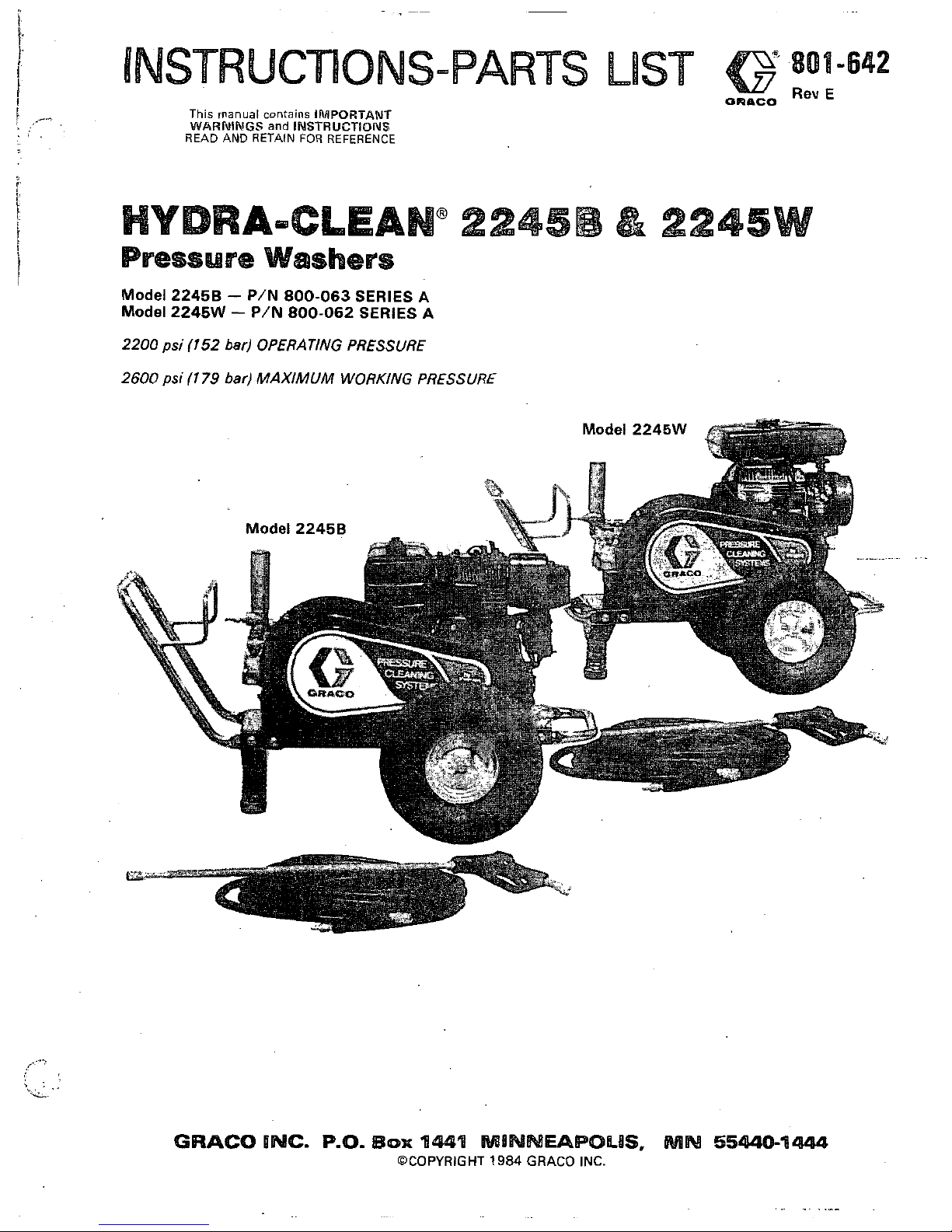
Model 22458 - PIN 800-063
SERIES
A
Model 2245W - P/N 800-062
SERIES
A
2200
psi
(152
bar) OPERATING PRESSURE
2600
psi
(1
79
bar)
MAXIMUM WORKING PRESSURE
GRACO
INC.
P.O.
IBOX
144'8
M8NWBEAPOLUS.
MM
55440-1444
OCOPYRIGHT
1984
GRACO INC.
. .~
. .
. ."
Page 2
,
M$
E
(-.Too
AzA
~
~~~~~~~~?~,~~~~~~~~.~~~~~~~~~"~~
II_
~-,'"-~~~~.~~-*,~.~~~i~~.~,~:,~
Fluids under high pressure from spray or leaks can
penetrate the skin and cause extremely serious
injury, including the need for amputation.
NEVER
point the spray gun
at
anyone or any part of
the body.
NEVER
put hand or fingers over the spray tip.
NEVER
try to stop or deflect leaks with your.hand or
body.
ALWAYS
have the tip guard
in
place when spraying.
MEDICAL
TWEA~~~~T~~~~~~~~~~:~~~~~~~~~~~~~!~,~~
If
any fluid appears to penetrate your skin, get
EMERGENCY MEDICAL CARE
AT
ONCE.
DO
NOT TREAT
AS
A
SIMPLE
CUT.
Tell the doctor exactly what fluid was injected. For
treatment instructions have your doctor call the
NATIONAL POISON CENTER NETWORK
(4.1
2)684
-6669
AVOID
CoMpOpJENT
R~p~U~~.~~~~~~~~~~~
high pressure in the pump, hose'and gun until you
Even after you shut off the gasoline engine, there
is
the spray tip or servicing the unit,
always
shut offthe
release
it
by triggering the gun.
So
before removing
unit
and
trigger the gun
to
release pressure.
components will withstand the pressure developed.
Be sure that
all
accessory items and system
NEVER
exceed the pressure rating of any component
in system..NEVER alter or modify equipment -your
personal safety, as well as the function of the
equipment,
isat
stake. Maximum working pressure
2600
PSI
(179
bar).
Before each use, check hose for weak, worn ordamaged
conditions caused by traffic, sharp corners, pinching or
kinking. Tighten
all
fluid connections securely before
each use. Replace any damaged hose.
Do
not use chemicals or agents which are not compatible
with Buna-N and
PVC
or neoprene cover of hose.
Do
not leave a ~ressurized unit unattended. Shutoff the
F,
E
~~~~~~~~~~~~~~~~~~~~~~~~.~~~~~~~~~~"~"~~~.~~'?~~~~,.~~,~~~~~~~,:~"'
%%~.*-~,
_._,_
a:,~..~*
~-~r.~;~~*.~,.~~~~~~~~~.~~~~
engine where combustible fumes or dust may be
Do
not spray flammable liquids.
Do
not operate the
present.
GAS
E[V160NE
pRE@AUTION$
~~~-~~~~~~~~~~~~
NEVER
fill fuel tank while engine is running or hot.
Avoid the possibility
of
spilled fuel causing a fire.
Always refuel slowly
to
avoid spillage.
NEVER
operate engine in a closed building unlessthe
carbon monoxide,
a
poisonous, odorless and invisible
exhaust is piped outside. The exhaust contains
gas. which, if breathed, may cause serious illness or
possibly death.
NEVER
make adjustments on machinery while it
is
connected to the engine; first remove the ignition
cable from the spark plug. Turning over the
machinery by hand during adjusting or cleaning
might start the engine and machinery, causing
serious injury to the operator.
NEVER
run the engine with governor disconnected,
or operate at speeds
in
excess of
3600
RPM
load.
Precaution
is
the best insurance against anaccident.
When starting the engine, maintain
a
safe distance
from moving parts of the equipment.
GEI\J
EWAk
~~~~~~!~~~~~~~~~~~~~~~~:~~~~~~~~~~~~~~~~~~:~~~~,~~
")Lnr_;lu",~r,~~-~.~~rr~,;~"""--rci,.-lje,
'#&<~
""S"
NEVER
run the unit with the belt guard removed.
Keep clear of moving parts when the unit is running.
Observe detergent manufacturer's safety
precautions. Avoid getting detergent or other liquids
in your eyes. Follow the directions on the container
breathing
fumes, etc. Always wear full
goggles to
regarding
contact with eyes. nose,
and skin,
protect your eyes from the spray
as
well asanydebris
dislodged by the spray. If necessary, wear gloves or
other protective clothing. If antidotes or treatment
are recommended, be prepared to use them.
DON'T
spray toxic chemicals such as insecticide or
weed killer.
unit and release pressure before leaving.
IMPORTANT
.. .
..
United States Government safety standards have been adopted under the Occupational Safety and Health Act.
These standards -particularly the General Standards, Part
191
0.
and the Construction Standards. Part
1926
-
should be consulted
in
conneciion with your use of airless spray equipment.
2
801-642
Page 3

rENGlNE
KILL
BUTTON
the unit.
Refer to the engine instruction booklet provided with
Install Hose and Spray
Gun
Connect the spray hose to the spray gun by inserting
the pin at the end of the hose into the quick
the fluid outlet in the same way.
disconnect coupler on
the gun. Connect the hose to
Cleaning Accessories
For spraying detergent or other cleaning solution, we
recommend using
a
chemical injector kit.
See
Accessories and instruction manual
801-645
for
installation and operation.
For removing rust andold paintwe recommend using
3
a
watersandblaster. SeeAccessories andinstruction
manual
801
-646
for installation and operation.
.'
.
,,
!.
.
,c".>,
,..~".>.
Connect
To
Water
Supply
CAUTION
plumbing code regarding cross-connection to
Before attaching to water supply, check local
water supply.
pump
in
a
direct
supply system.
Do
not exceed
1
6O0F
(7OOC) water temperature to
Connect a hose with at least a
3/4
in.
(19
mm)
ID
from your city water supply to the unit's
3/4
in.
garden hose threaded inlet. The supply hose should
not be more than
50
ft.
(15
m) long.
NOTE:
For a direct supply system, your water
AT LEAST 5 GPM
(19
LITER/MIN).
source at the unit
musf
have a flow rate
of
contact our Customer Service Department for
If
your operating conditions are different from above.
assistance.
801-642
3
Page 4

Startup
Before starting, be sure to read the safety warnings and
setup instructions.
Check the oil and gasoline levels daily
Turn on
the
water supply.
Trigger the gun to release any back pressure.
Set the choke and open the fuel valve.
NOTE:
For easier starting, hold the gun trigger open
while pullino
the
rope.
Put your foot
on
the frame or wheel to steady the unit
when you pull the starter rope. Hold the gun in~your left
hand with the trigger open while starting the engine.
Grasp the starter rope grip and rapidly pull out the cord
two
or three feet
I1
m). Repeat
if
necessary with the
choke opened slightly. When the engine starts, im-
mediately release the gun trigger. Open the choke
gradually.
the pump will result. Always be sure watersupply
is comDletely turned on before operating.
~~~ ~
Inspect
all
connections for any leaks. Tighten
if
necessary.
Cleaning
For Hydra-Clean technique. see th,e Chemical Injector
manual, 801
-645.
For abrasive cleaning, see the Water Sandblaster
manual, 801
-646.
1.
Shut
off
the cleaning unit and trigger the gun
to relieve pressure. Engage the trigger safety.
2.
Keep the nozzle and the tube pointed away
from you and everyone else.
3.
Do
not put your hand over the
tip
to
push the
nozzle into place. Grasp
it
'from the side and
keep your fingers away from the tip.
4.
Do
not let anyone else touch the spray valve
while you are cleaning nozzles.
5.
Be sure the slip ring
is
pushed forward to lock
the nozzle in place before triggering the spray
When unit is not in use, turn off water supply.
Shutdown and Care
Of
Unit
When shutting down for the day or weekend, shut off
unit, shut off water supply valve, and trigger gun to
release pressure. Wipe off the unit with
a
damp rag.
for longer pump life. The pump
will
overheat if left
running for over
10
minutes without spraying.
~ ~~
Check !he filter screen in the water inlet connection as
often as necessary,
at
least daily.
Do
not operate the
unit with the inlet and filter screen removed.
engine speed. Changing these settings may cause exces-
DO
NOT
try to adjust the unloader valve or change the
sive pressure, intermittent unloader operation, wasted fuel
and increased wear
on
parts and
will
void the warranty.
PUMP MUST NOT BE RUN
DRY
and must be drained
of
water prior
to
exposure to freezing temperatures. Use
and store the unit where
it
will not be subjected to
freezing temperatures. If water does freeze in the unit,
thaw before trying to start. A
50%
anti-freeze solution
may be pumped prior
to
cold weather storage.
Use only spray tips that are matched to the unit to avoid
excessive cycling and wear of the unloader valve. See
ACCESSORIES.
~~ ~ ~
pour hot water on a frozen pump. A sudden
temperature change may crack the ceramic
plungers.
Do
not
pump caustic materials.
Before extended storage, flush the pump with light oil.
Avoid dragging hose over
an
abrasive surface such as
cement. This causes excessive wear and shorter hose
life.
Clean the intake line strainer daily
Lubrication and Care
tion. Drain oil with engine warm. Engine requires
3
Change the engine oil after every
100
hours of opera-
pints
(1.4
liters)
30W
oil. See separate instruction
manual for maintenance procedures.
Fill pump crankcase to dot
on
oil gauge window with
or equivalent
SAE
40
weight hydraulic oil with anti-
34
oz. (1.0 liters) of crankcase oil (part no.
801-1441
wear and rust inhibitor additives. Change initial fill
after
50
hour running period. Change
oil
every
3
months or
at
500
hour intervals.
Altering or adjusting unloader
willnor
increase
performance of unit.
qualified service personnel.
Service of the unloader must be performed only by
.,
..
4
801-642
..
.
.. . .
..
-
.
..
..~
..
....
.
.
-
..~
.
Page 5

'ROBLEM
kgine Will Not Start
3r Hard To Start.
Engine Misses Or Lacks
'ower
-ow Pressure
Pump runs extremely rough,
xessure low.
mater leaka e from under
the manifoldl
Water in pump crankcase.
Frequent orprematurefailure
ztf
the packing.
Strong surging at the inlet
and
low
pressure on the
jischarge side.
CAUSE
ca'rburetor.
No gasoline
in
fuel tank or
Water
in
gasoline or old fuel.
Choked improperly. Flooded
engine.
Dirty carburetor air filter.
Spark plug dirty or improper
gapSpray gun closed.
Partially plugged air filter.
Spark plug dirty, wrong gap,
or wrong type.
Incorrect ignition timing.
Worn nozzle.
Belt slippage.
Air leak
in
inlet plumbing.
Relief valve stuck, partially
plugged or improperly
adlusted; valve seat worn.
Inlet suctiqn strainer clogged
or
Improper sue.
Worn packing. Abrasives
in
pumped fluid or severe cavitation. Inadequate water supply.
valves.
Fouled or dirty inlet or discharge
Worn inlet or discharge valves.
Leaky discharge hose
the inlet plumbing.
Restricted inlet or air entering
-
Inlet restrictions and/or air
leaks. Stuck inlet or dlscharge
valve
Leaking
H.P.
seals.
Worn packing.
condenslng into water lnslde the
May be caused by humid,air
crankcase.
Scored plungers.
Over pressure to inlet manifold.
Damaged or worn dunpers.
.
Abrasive material
in
the fluid
being pumped.
Excessive pressure and/or
temperature
of
fluid being
pumped.
Over pressure of pumps.
Running pump dry.
Foreign particles in the inlet or
iischarge valve, or worn inlet
jnd/or discharge valves.
SOLUTION
Fill the tank with gasoline, open fuel shut-off
valve.
Check fuel line and carburetor.
Drain fuel tank and carburetor. Use new fUe
and dry spark plug.
Open choke and crank engine several timest(
clear out the gas.
Remove and clean.
Clean, adjust the gap or replace.
Trigger spray gun.
Remove and clean.
Clean, adjust the gap, or replace.
Time engine.
Replace with nozzle of proper size.
Tighten or replace; use correct belts and replace
both at same time.
Disassemble, reseal, and reassemble.
Clean, and adjust relief valve; check for worr
and dirty valve seats.
Kit
available.
frequently.
Clean. Use adequate size. Check more
Install proper filter. Check flow.available
to
pump.
Clean inlet and discharge valve assemblies.
discharge hose.
Replace worn valves, valve seats and/or
seal.
Proper size inlet plumbing; check for air tighi
Clean out foreign material, replace worn valves.
Replace seals
Install new packing
Change oil at
3
month or
500
Hour intervals using
200
hours) P.N.
801-f44.
Crankcase Oil (other ap roved oil every month or
Replace plungers.
Reduce inlet pressure.
Replace plungers.
Install proper filtration on pump inlet plumbing.
Check pressures and fluid inlet temperature; be
sure they are
within
specified range.
Reduce pressure.
Do not run pump without water.
Check for smooth lap surfaces on inlet and
dischar e valve seats. Discharge valve seats and
inlet va
9
ve seats may be lapped on a veryfine oil
stone.
"
..
.
801-642
5
.
..
Page 6

6
801-642
_-
~,.
.
.
. .
.~,.
-..
..
.
Page 7

1
I
,
NO. NO.
REF. PART
I
.~
!
1
800-130
3
'801-666
2
*801-665
4
800-056
5I
801-494
801-283
6
800-067
!
!
7 801-724
8
801-506
9{::;::::
10
801-130
11 801-141
12 801-129
13 801-543
14 801-131
15 801-022
16 801.941
17
801-942
18
801-531
19 801-546
20
801-559
21 801.015
22
801-023
23 801.363
24 801-025
25 801-521
26
801-520
27 801-024
28
801-499
29 801-020
30 801.538
31 801-007
32 801-004
801.898
33€80i-376
DESCRIPTION
ON.
drawing/list page
10
GUN ASSEMBLY,
see parts
1
TIP,
0006
MEG. 1/4 thd..
O'
TIP,
1506
MEG. 1 /4 thd.. 15O
1
1
drawingAist page
9
PUMP ASSEMBLY, see parts
1
ENGINE,
11
h.p. (Model
22458)
ENGINE,
1 1
h.p. (Model 2245W)
1'
CHASSIS WELDMENT
LABEL, Model 2245
1
BOOT. lea
1
1
BELT,'drive (Model
22458)
BELT. drive (Model
2245Wl
LABEL.
warning
1
LABEL. warning
LAEEL, warning
DECAL, GracdVangard
PLATE, serial no.
SCREW, hex, 5/16'-18 x 1-3/4
SCREW, hex, 5/16-18 x 1
"
SCREW, hex, 5/16-18 x 3"
SCREW, hex, 3/8-16 x
7"
SCREW, hex, 3/8-16 x
1-1/4
SCREW, hex,
M8
x
30
MM
WASHER, flat,
5/16
WASHER, flat. 1/4
WASHER. lock. 5/16
WASHER,
lock,
3/8
RAIL
STIFFNER
WELDMENT
NUT, hex, 5/16-18
RAIL STIFFNER BRACKET
NUT. lockino. 3/8-16
NUT, locking; 1/2-13
GROMMET
HOSE, H.P.. 1/4 x
50
ft.
PULLEY, pump
HUB, pulley (Model
22456)
HUB, pulley (Model 2245W)
1
1
1
1
4
7
1
1
4
4
5
24
4
20
1
11
1
2
1
5
1
REF.
PUMP
34 801-135 HUB. pulley
NO.
NO.
DESCRIPTION
ON.
35 801.896 PULLEY. enoine
1
1
36 '801 -090 QUICK COUIPLE. male.
1
/4
37 '801-009
5
38 801-541
QUICK COUPLE, female 2
HANDLE
39 801-364
1
BELTGUARD COVER
1
40
801-500
42
801-505
41 801-539
43 801-537
44
801-556
46 801-137
45 801-504
47 801-593
48 801-550
49 "801 -583
50
"801-588
51
'801-552
52 '801.553
53 801-132
54 801-610
BELTGUARD EASE
BUMPER
FOOT
RETAINER
WELDMENT, leg support
AXLE
FOOT
KEY
WHEEL
SPRING,
6"
DEFLECTOR, heat
TIP,
2506
MEG, 1/4
thd.,
25O
SCREW, deflector
TIP, 4006 MEG. 114
thd.,
40°
RIVET, drive
BRACKET.
sumon
1
1
1
1
1
1
1
'2
1
1
2
1
1
2
1
55
801-608
PIN. roll
56
801-605 SCREW. hex. #lo-24 x 3/4
1
1
.
~.
~
57 801-875 WASHER, lock, #10
58
801.606
1
WASHER. flat. 3/16
1
59 801-367 BUMPER
60
801-612 WASHER. flat. 7/16
..
61
801
-676 SPACER, 'beltguard
4
62 801.555
63 801-731
LABEL, chk.
oil
1
BUMPER
64 801-103 NIPPLE, hex. 1/4
x
3/8
2
65
801-922 NUT, adjusting
1
66
800-156 NUT, weldment
3
67 801-940 SCREW, hex, 5/16-18~3/4
1
1
Order
parts
by
name and series letter
of
the assembly for
which
you
are ordering.
""Model
22458
Only
-
not
included
on
Model
2245W.
'Recommended
"tool
box"
spare parts.
Unloader Assembly, 800-045
2000
PSI
(138
bar)
Max.
"1
2
e17
1
12
PARTS LIST
~~~~~~~~~~~~~~~~~~~~~~?~~~~~~~
Unloader Assembly, 800-045
REF. PART
NO. NO.
1
801-045 CAGE, valve
DESCRIPTION
ON.
1
2
801-046 O-RING
3 801-047
1
SPRING
4 801-048
1
5
801-049
BALL
1
SEAT
6
801-050
O-RING
1
2
7 800-123 UNLOADER SUB-ASSEMBLY
8
801-059
1
9 801-412
O-RING 1
10
801.432
HOUSING 1
CYLINDER
11. 801-062 O-RING
1
12 801-063 PLUG
2
1
13
801-068
HOUSING VALVE
14 801.069 SPRING
15 801 -070 VALVE
16 801-071
17 801-939
SEAT
O-RING
Order parts
by
name and series letter
of
the assembly for
which
you
are
ordering.
801-642
7
~.
.
Page 8

MOTE:
Two sizes of metric wrenchesare necessary
for servicing the pump; M13 and M30.
Valves:
1.
Remove the hexplug(5)from manifold(6)using
M30
wrench.
2. Examine O-ring
(4)
under plug and replace if cuts or
distortion exist.
3. Remove valve unit and O-ring (3) from cavity.
NOTE:
Valve unit
maycomeapartduringremoval.
4.
Replace valve unit
with
P/N 801 -472
5. Replace hex plug
and
torque to 75ft. Ibs. (10.3 K/m).
MOTE:
Hex plug should be re-torqued after
5
hours operation.
Pumping Section:
1.
Remove the eight cap screws
(1)
from the manifold
using the M13 wrench.
2.
Carefully separate the manifold from the crankcase.
NOTE:
It
may be necessary to tap manifold lightly
with mallet to loosen.
CAUTION
Keep manifold properly aligned with ceramic
I
I.
plungers when removing
to
avoid damage to
plungers or seals.
I
3.
Carefully examine each plunger (16)for any scoring
and replace
if
necessary.
Servicing Plungers:
1.
Loosen plunger retaining screw(l215-6 turns, using
This will separate plunger and retaining screw.
"10 wrench. Push plunger towards crankcase.
2. Remove retaining screw from plunger and examine
O-ring (181, back-up ring (17). and copper
bearing/gasket washer
(1
3). Replace if necessary
using plunger repair kit
P/N
801 -474.
3.
Remove plunger from plunger rod and remove
copper flinger (15). Clean or replace
if
necessary.
4.
Lightly grease flinger and replace
it
on plunger rod.
5. Replace plunger.
6. Lightly grease retaining screw assembly to avoid
cutting O-ring. Lightly grease outer end of plunger.
7. Install retaining screw assembly into plunger and
torque to 14.4
ft.
Ibs. (2 K/m).
8. Lubricate each plunger and carefully slide manifold
onto crankcase.
9. Replace the eight capscrews and snug them up.
Torque to 21.7
ft.
Ibs. (3 K/m).
NOTE:
The eight capscrews must be torqued
evenly to apply equal pressure on the
doesn't bind or jam. This
is
best done by
manifold
so
that
it
seats properly and
torquing bolts closest to the center of the
those bolts.
manifold first and then working out from
Servicing V-Packings:
NOTE:
Use packing repair kit PIN 801 -486
1. After removing the eight capscrews and the
manifoldcarefullypull packing retainer(l9)fromthe
necessary.
manifold. Examine O-ring (10) and replace
if
2. Remove low pressure packing
(8)
and head ring
(7).
3. Pull intermediate retainer ring (20) from manifold.
and head ring
(7).
Remove long life ring
(9).
high pressure packing
(81
4.
Inspect all parts and replace if necessary.
NOTE:
If
just the packings are needed use kit801
-
486. If rings or retainers need replacement
use kit 801 -487.
5.
Thoroughly clean packing cavity in manifold and
examine. Lightly grease packing cavity.
6.
Replace packing assembly
in
the following order:
intermediate ring (20). head ring (7). packing (8),
head ring
(71,
packing
(8).
long life ring
(9),
packing retainer (191. and O-ring
(10).
CAUTION
position of the seals
to
assure proper reassembly
Carefully study the location of each part and the
and operation.
7.
Lubricate each plunger and carefully slide manifold
onto crankcase.
NOTE:
When replacing the manifold onto
plungers. extreme caution should be
exercised to avoid damage to the seals.
8.
Replace the eight capscrews in the manifold and
tighten
as
previously described (step 9 under
servicing plungers).
8
801-642
Page 9

Page 10

SERVICE
?(
8
Gun,
Cartridge
Replacement
1.
Press access pin
(1
2)
from gun handle and remove
access plate
(14)
by
sliding plate backwards.
Remove cartridge
(5)
from housing
(6)
by using a
19
rnm
socket wrench.
2.
ChecK inside housing to be sure all O-rings came
out when cartridge was removed.
If
O-ring can be
seen inside the housing, remove
it,
being careful
not to damage internal threads
in
housing.
3.
Throw away old cartridge and
install
new cartridge
using
a
Small amount of pipe sealant
on
threads.
Be
suretotightencartridgefirmlyagainst
housing,
4.
Slide access plate into place and install access pin.
REF. PART
NO.
NO.
DESCRIPTION
QTY
1
801-134
~
TUBE, 32"
2
801-674
GRIP
1
1
3 801-009 COUPLER,
female
quick dismnnect
'
1
4 801-638
SPRAY
GUN,
(replaceable
Darts
include
items
5-1RI
5 801-639
6
801-671 HOUSING
~ ~
~.~
.
.
.
-,
:
CARTRIDGE
7
801-670
.
HEX PLUG
9
801-424
8
801-256
.
TRIGGER
PIN
TRIGGFR
10
801-672
OUTLET
11 801-673
.
PIN
COVER
12 801.428
ACCESS
PIN
13 801-419
.
HANDLE
~ .
.
.
- -
-
. .
14 801-427
.
ACCESS PLATE
15 801-420
.
TUBE
1
1
1
1
1
16 801-423
.
INLET FllTlNG
1
17 '801
-202
O-RING,
quick
couple
1
which
you
are ordering.
Order parts
by
name and series letter
of
the assembly for
Wecommended
"fool
box"
spare parts.
Page 11

ACCESSORIES
(Must
be
purchased
separately)
~~~~~~~-~~~~~~~~,~"~~~~~~~~~~~~.~~~~~~~~~~~~~~~~~~~.~,~~~~
CHEMICAL.INJECTOR KIT
800-1
11
WATER SANDBLASTER
800-120
For injecting harsh cleaning chemicals downstream
from pump. Spray tip not included
in
kit.
For abrasive cleaning
of
stubborn dirt and paint.
BACK
FLOW
PREVENTOR
801-133
SANDBLASTER
SPRAY
TIP
801-666
supply. Install upstream from pump.
Prevent back-up of contaminated water into fresh
TECHNICAL DATA
22458
ENGINE: BRIGGS
E
STRATTON
4
cycle. single cylinder.
air cooled, 11 h.p.
GASOLINE TANK:
6
quarts (5.7 liter)
capacity
WATER PUMP 2200 PSI (1 52.har)max.
pressure; 4-1/2 GPM
(17 iiler/min).
WETTED PARTS: Stainless Steel, Aluminum,
Phenolic Plastic. Ceramic
Liners. Nitrile Rubber.
UNIT WEIGHT: 21
3
Ib (97 kg)
OVERALL DIMENSION: "Length: 44
(1
118
mm)
Width: 31" (787
mml
Height: 26"
(660
mm)
.
,,
MAX. WATER TEMPERATURE 160°
(70'
C)
INLET HOSE CONNECTION:
3/4"
garden hose'(f\
...
2245W
WlSC
4
cycle. single cylinder.
air
cooled. 11
h.p.
6.2
quarts
(6
liter)
capacity
2200 PSI (152
bar)
max
pressure; 4-1/2 GPM
I17 liter/min).
Stainless Steel, Aluminum,
Phenolic Plastic. Ceramic
Liners, Nitrile Rubber.
222
Ih
I101 kg)
iength:
44"
(1 118
mm)
Width: 31" (787
mm)
Height: 28"
(71
1
mm)
1
60°
(70°
C)
3/4"
garden
hose
(f)
801-642
41
Page 12

THE
GRACOWARRANTY
Graco Inc. warrants
all
equipment manulactured by
it
and bearing
,IS
name
to
be free
from
delects in
purchaserforaperiodof
12monthslromthedateolpurchaseandappliesanlywhentheequipment
material and workmanship under normal
use
and seivice. This warranty extends
to
the wiganal
is installed and operated
in
accordance with
writtenlactoryrecommendations.
This warrantydaes
not
cover
damage
or
wear which:
in
the reasonable judgment of Graco.
arms
lrom
misuse.
abrasion. corrosion. negligence. accident. substitution
of
non-Graco parts. faulty
installation
or
tampering.
This warranty
is
conditioned upon the prepaid return
01
the equipment claimed
Io
be defective
for
examination by Graco
to
verily
the
claimed defect.
If
the claimeddefect is
verified.
Graco
will
repa~r
or replace tree
of
charge. any defective parts.
The
equipment
will
be returned
IO
the origlnal
purchaser transportallon prepaid.
II
inspection
01
the equipment does
not
disclose any defect
in
workmanshipormalerial.repairswillbemadeatareasonablechargeandreturntransportat~onwill
be
charged.
..
.
.,
(
,
'.
..,
,
Subsidiary
and
Affiliate
Cornpa-
Canada: England: Switzerland: France: Germany; Hang Kong: Jspan
Factiwv
Branches
Atlanta. Dallaa. Detroit. Los Angelea, West Caldwell iN.J.1
GRACO
INC.
P.O.
BOX
1441
MINNEAPOLIS,
RAN
55440-1444
PRINTED IN U.S.A.
801-642
4/85
45-10059
REV
E
.
..
..
 Loading...