

Page 1
INSTRUCTIONS–PARTS
LIST
308–188
This
manual contains IMPORT
W
ARNINGS AND INSTRUCTIONS
READ AND RET
AIN FOR REFERENCE
ANT
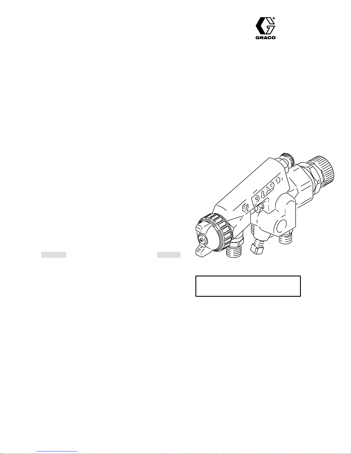
Model H.E.L.P. 1600B
HIGH EFFICIENCY
LOW PRESSURE
AUTOMATIC
STAINLESS STEEL FLUID PASSAGES
300
psi (21 bar) MAXIMUM WORKING FLUID PRESSURE
100
psi (7 bar) MAXIMUM WORKING AIR PRESSURE*
15
psi (1.05 bar) MAXIMUM OPERA
*The
Maximum Working Air Pressure
sure
the gun was designed to operate safely under
**The
Maximum Operating Air Pressure
pressure
pressures are maintained at or below 15 psi (1.05 bar), the
natural pressure drop through the gun will produce 10 psi
(0.7
allowable to guarantee HVLP compliance. If input
bar) maximum air cap pressure.
BLEEDER AIR SPRA
TING AIR PRESSURE**
is the maximum air pres
.
is the maximum inlet air
-
Rev A
Y GUN
TABLE OF CONTENTS
Warnings 2.
Typical Installation 3.
Installation 3
Operation 4
Maintenance 6
Troubleshooting
Service 8
Important
Dimensional
Parts
Accessories 11
Technical
Air
Flow Charts
Warranty Back
. . . . . . . . . . . . . . . . . . . . . . . . . . . . . . . . . . . .
. . . . . . . . . . . . . . . . . . . . . . . . . . .
. . . . . . . . . . . . . . . . . . . . . . . . . . . . . . . . . . .
. . . . . . . . . . . . . . . . . . . . . . . . . . . . . . . . . . . . .
. . . . . . . . . . . . . . . . . . . . . . . . . . . . . . . . . .
Charts6. . . . . . . . . . . . . . . . . . . . . . .
. . . . . . . . . . . . . . . . . . . . . . . . . . . . . . . . . . . . . . .
Phone Numbers8. . . . . . . . . . . . . . . . . . . . .
Drawing9. . . . . . . . . . . . . . . . . . . . . . . . . .
Drawing and List
. . . . . . . . . . . . . . . . . . . . . . . . . . . . . . . . .
Data
.
. . . . . . . . . . . . . . . . . . . . . .
.
. . . . . . . . . . . . . . . . . . . . .
.
. . . . . . . . . . . . . . . . . . . . . . . . . . .
. . . . . . . . . . . . . . . . . . . . . .
Back Cover
Back Cover
Cover
10.
Part No. 224–891
Includes
0.032 in. (0.8 mm) fluid nozzle
GRACO INC. P.O. BOX 1441 MINNEAPOLIS, MN 55440–1441
COPYRIGHT
1991 GRACO INC.
Page 2

WARNINGS
FOR PROFESSIONAL USE ONLY. OBSERVE ALL WARNINGS.
Read and understand all instruction manuals, tags,
and warning labels before operating equipment.
EQUIPMENT
MISUSE
HAZARD
General Safety
Any
misuse of the
as
over
pressurizing, modifying parts, using incompatible
chemicals and fluids, or using worn or damaged parts,
can cause them to rupture and result in serious bodily
injury,
fire, explosion or property damage.
NEVER point the spray gun at anyone or at any part of
the
body
. NEVER put hand or fingers over the spray noz
zle.
ALWAYS
before
any
NEVER try to stop or deflect leaks with your hand or
body.
NEVER
so
CHECK all spray equipment regularly and repair or
replace
follow the
cleaning or removing
system equipment.
alter or modify any part of this equipment; doing
could cause it to malfunction.
worn or damaged parts immediately
spray equipment or accessories, such
Pressure Relief Procedure
the fluid nozzle or servicing
, at
right,
.
Fluid Compatibility
BE SURE all fluids and solvents used are chemically
compatible
NICAL DATA on the back cover. Always read the fluid
and solvent manufacturer’s literature before using the
fluid
or solvent in this gun.
with the “W
etted Parts” shown in the
Pressure Relief Procedure
-
To reduce the risk of serious bodily injury, including
splashing
parts,
system,
system, when installing, cleaning or changing fluid nozzles,
1. T
2. Trigger the gun into a grounded metal waste con-
in the eyes or on the skin or injury from moving
always follow this procedure when shutting off the
when checking or servicing
and whenever you stop spraying.
urn of
f the air and fluid supply to the gun.
tainer
to relieve air and fluid pressure.
any part of the spray
TECH-
System Pressure
This gun has a
SURE
of 300 psi (21 bar), a
PRESSURE
AIR PRESSURE
ATING
ceed the maximum working pressure of the gun or any
other
component or accessory used in the system.
MAXIMUM WORKING FLUID PRES-
MAXIMUM WORKING AIR
of 100 psi (7 bar) and a
of 15 psi (1.05
MAXIMUM
bar). NEVER ex
OPER
-
-
HOSE SAFETY
TIGHTEN
NEVER use a damaged hose. Before each use, check
the
damage or movement of the hose couplings. If any of
these
United
all fluid connections securely before each use.
entire hose for cuts, leaks, abrasion, bulging cover
conditions exist, replace the hose immediately
, or
.
HANDLE AND ROUTE HOSES CAREFULLY. Do not
on hoses to move equipment. Do not use fluids or sol
pull
vents which are not compatible with the inner tube and
cover
of the hose.
IMPORTANT
States Government safety standards have been adopted under the Occupational Safety and Health Act. These stan
dards––particularly the General Standards, Part 1910 and the Construction Standards, Part 1926––should be consulted.
-
-
Page 3
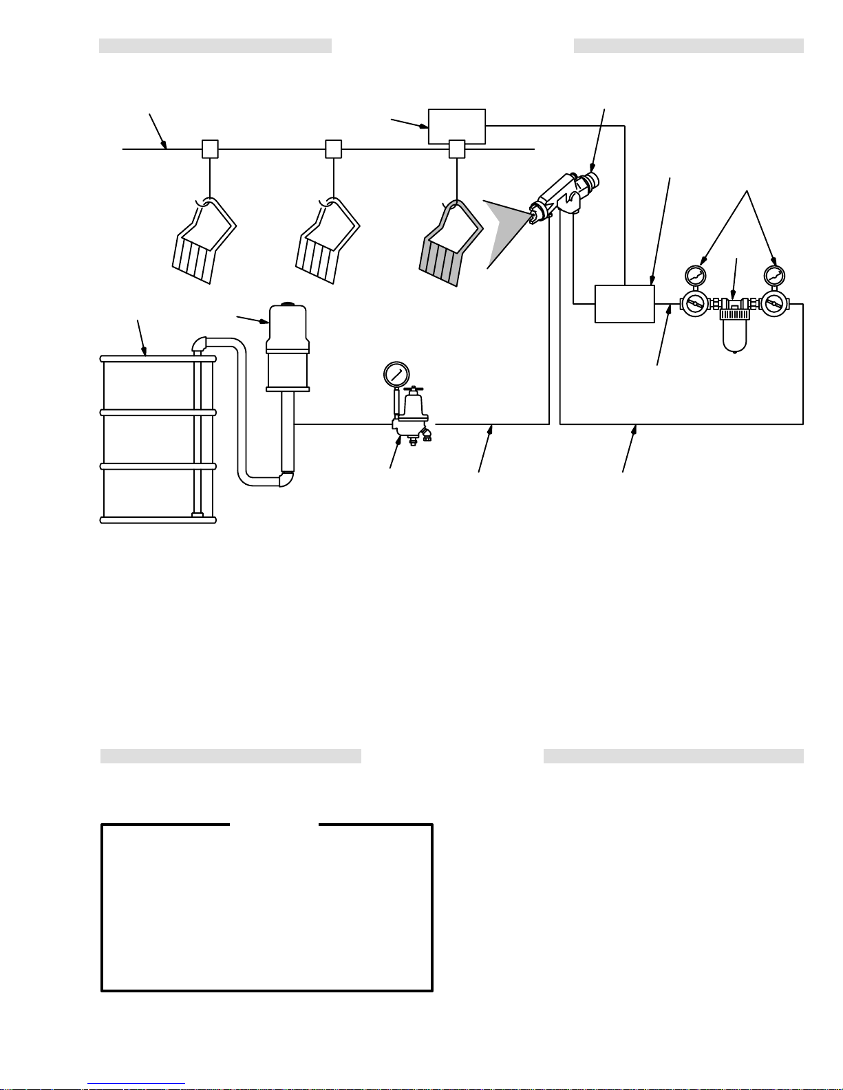
TYPICAL INSTALLATION
Conveyor
Fluid
Supply
Pump
Sensing
Device
Fluid
Pressure
Regulator
Fluid
Line
H.E.L.P.
Bleeder Air Spray Gun
Cylinder Air
Supply Line
Atomizing Air
Supply Line
1600B Automatic
3-way
Air
Solenoid
Valve
Air Regulator
Air
Filter
0896
The
Model H.E.L.P
Bleeder Spray Gun
. 1600B High Ef
was
designed to produce the highest
ficiency Low
Pressure
quality finish with today’s fluids as well as the the Low
V.O.C.
(volatile organic compound)
fluids of tomorrow
.
This spray gun can spray most coatings or finishes currently
being used
for automotive refinish, industrial, aero
space, marine, wood, plastic and architectural applications,
while easily operating from any paint delivery sys
tem, including pressure pots of any size, or remote
pumps
for production line operation.
INSTALLATION
Ventilate the Spray Booth
WARNING
To prevent hazardous concentrations of toxic
and/or
flammable vapors, spray only in a properly
ventilated
gun unless ventilation fans are operating.
Check and follow all of the National, State and
Local codes regarding air exhaust velocity
requirements.
Check
spray booth. Never operate the spray
and follow all local safety and fire codes.
If input air pressures are maintained at or below 15 psi
(1.05
bar), maximum air
bar),
which is required to meet all new regulations.
cap pressure will be 10 psi (0.7
The Typical Installation shown above is only a guide for
selecting
tomatic spray system. It is not an
-
and installing the equipment needed for an au
actual system design.
For assistance in designing a system, contact your
-
representative.
Graco
Mount the Gun
Mount
the gun on a 0.50 in. (12 mm) diameter rod mount
ing fixture that allows adjustment of the spray pattern
direction
and the distance from the workpiece.
Connect the Fluid Line
1. Before connecting the fluid line, blow it out with air
and flush it with solvent. Use solvent which is compatible
with the fluid to be sprayed.
2. Install
a fluid regulator on the fluid line to control fluid
pressure
to the gun.
-
-
3. Connect
gun
fluid inlet.
the fluid line to the 3/8–18 npsm (R 3/8–19)
Page 4
INSTALLATION
Connect the Air Lines
1. Install
2. Install
3. Connect
4. Install
Pressure Relief Procedure
To
splashing in the eyes or on the skin or injury from
moving parts, always follow this procedure when
shutting
any part of the spray system, when installing,
cleaning or changing fluid nozzles, and whenever
you
1. T
2. Trigger the gun into a grounded metal waste
an air filter to provide a clean, dry air supply to
the
gun. Dirt and moisture in the air line can af
appearance
the
cylinder air supply line. Connect an air hose from
the solenoid valve to the 1/4–18 npsm (R 1/4–19)
gun
air inlet marked CYL.
NH (standard garden hose fitting) gun air inlet
marked ATOM.
and
cylinder air
reduce the risk
stop spraying.
urn of
container
of your finished workpiece.
a normally closed, 3-way air solenoid valve in
an
atomizing air supply line to the 3/4–1
separate air regulators to control atomizing air
.
WARNING
of serious bodily injury
of
f the system, when
f the air and fluid supply to the gun.
to relieve fluid pressure.
checking or servicing
, including
Recommended Hose Sizes
fect the
FLUID HOSE
Length
Needed
0–35
1.5
(0–11 m)
35–100 ft
(11–30 m)
100–20
(30–6
OPERATION
ft
0 f
0 m
(general purpose)
CYLINDER
AIR HOSE
ID
Length
(in.)
t
)
3/8
1/2
in.
3/4
in.
Needed
0–100 ft
(0–30 m)
100–20
0 m
(30–6
(in.)
5/16
0 f
t
3/8
)
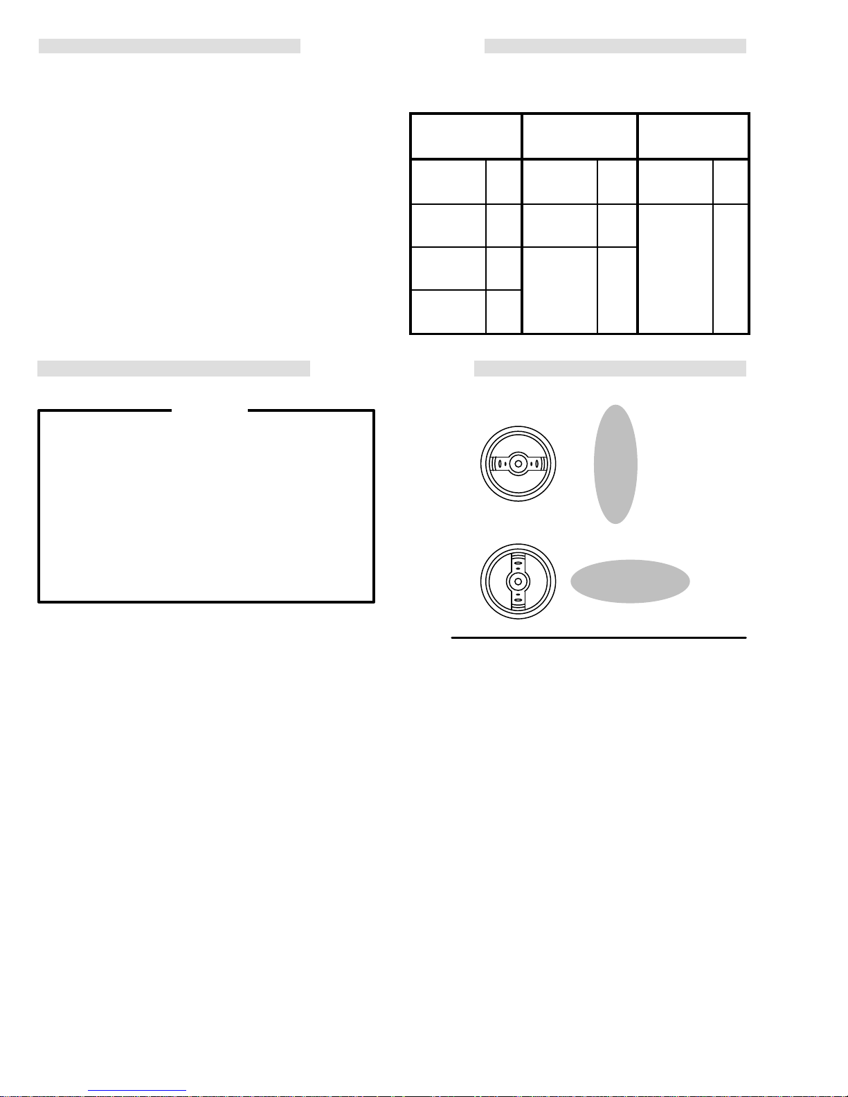
Vertical Pattern
ID
in.
in.
ATOMIZING
AIR HOSE
Length
Needed
0–25 ft
(0-7.63
m)
ID
(in.)
3/4
in.
Filter the Fluid and Check Viscosity
Filter the fluid to remove coarse particles and sediment
which
could clog the spray nozzle, then check the viscos
ity of your fluid. This gun is best suited for light to medium
fluids.
Light Fluid:
Furniture, Appliances, Fine Finish Metallics, Top Coats,
Lacquer,
Medium
tact Adhesive, Latex, Maintenance Paints, Textures,
Primers,
Heavy Fluid:
Polyurethanes, Heavy W
solid
19 to 24 seconds (No. 2 Zahn cup). Auto,
Enamel Primer
Fluid:
22 to 41 seconds
Epoxies, V
2.8 Volatile Organic Compounds, High-
.
(No. 2 Zahn cup). Con
inyls, High Flow High V
aterborne Enamels
iscosity.
Position the Air Cap
The direction of the spray pattern is controlled by the
position
cap
securely.
of the air cap. See Fig 1. Loosen and
to the desired position, then
hand tighten the air cap
turn the air
Adjust the Spray Pattern
Follow these steps to establish the correct fluid flow
air
flow:
4308-188
and
-
-
Horizontal Pattern
Fig
1
1. Adjust
NOTE:
2. T
NOTE: If
the pattern size by turning the pattern adjust
ing
valve
OUT (counterclockwise)
or
IN (clockwise)
2.
The pattern width at the widest adjustment is 10
to 11 in. (254 to 279 mm) at 350 grams/min. fluid
flow
and 10 in. (254 mm) target distance with 15
psi
(1.05 bar) inlet air pressure. (Measurements
taken using a 23 sec. Zahn #2 viscosity fluid.)
pattern length will vary with the fluid flow
The
pressure,
o adjust the volume of fluid output:
a. Turn the fluid adjusting valve all the way out
(counterclockwise)
b. Adjust the fluid regulator for the desired pres-
sure.
c. For final adjustment, turn the fluid adjusting
in
valve
output
the fluid adjusting valve is turned in all the way
the
gun will only emit air
for a narrower pattern
fluid viscosity
.
Refer to Fig 2.
(clockwise)
and obtain the desired results.
to
reduce the volume of fluid
for a wider pattern
.
Refer
, and other factors.
.
to
0897
-
Fig
, air
Page 5

3.
For
continuous spraying,
valve and fluid adjusting valve in the full open position.
This provides maximum fluid flow and prevents
premature
4. Test
the
gun about 6 to 8 inches (150 to 200 mm) from the
test piece. Adjust the air pressure to the gun until
proper
possible atomizing air pressure to obtain the de
est
sired
wear on the fluid nozzle.
the spray pattern and atomization while
atomization is achieved. Always use the low
results.
leave the pattern adjusting
OPERATION
To Operate the Gun
Adjust the system’s sensing device so the gun starts
spraying
the
holding
Air and Fluid Pressure
The gun requires 71 psi (4.9 bar) air pressure to the
-
-
The
The fluid pressure normally does not exceed 15 psi
just before meeting the workpiece
workpiece has passed.
cylinder.
atomizing air pressure must be set at or below 15
psi
(1.05 bar) for compliant operation.
(1.0 bar).
Pattern
Adjusting Valve
and stops as
Air Cap
Fig
2
Fluid
Needle
Fluid
Nozzle
Fluid Inlet
OM Air Inlet
AT
Fluid
Adjusting
Valve
308-1885
Page 6

Daily Care and Cleaning
WARNING
Pressure
To
reduce the risk
splashing in the eyes or on the skin or injury from
moving parts, always follow this procedure when
shutting
any part of the spray system, when installing,
cleaning or changing fluid nozzles, and whenever
you
1. T
2. Trigger the gun into a grounded metal waste
Clean all parts with a solvent compatible with the
fluid
parts.
Relief Procedure
of serious bodily injury
of
f the system, when
stop spraying.
urn of
f the air and fluid supply to the gun.
container
being sprayed and compatible with gun wetted
See TECHNICAL DATA
to relieve fluid pressure.
CAUTION
checking or servicing
on the back page.
, including
MAINTENANCE
1.
After operation, flush the gun with a compatible sol
vent
passages. Follow the Pressure Relief Procedure
Warning,
2. Wipe the outside of the gun clean with a solvent
dampened
3. Remove the air cap and fluid nozzle from the gun.
Soak them in solvent and scrub them with a fine,
bristled
4. To
clean out air
as a toothpick, to avoid damaging critical surfaces.
Clean the air cap and fluid nozzle daily, minimum.
(Some
5. Lubricate
daily
the needle spring (7) and cylinder with light-weight
grease
-
until all traces of paint are removed from the gun
at left, before proceeding.
cloth.
brush (provided with the gun).
cap holes, use a soft implement, such
applications require more frequent cleaning.)
the exposed portion of the fluid needle (1)
with Graco TSL or light oil. Periodically lubricate
or petroleum jelly
. See Fig 3, page 9.
To avoid getting solvent in the gun air passages,
NEVER
To avoid scratches that can distort the spray pattern,
in the air cap or fluid nozzle .
To
splashing
always follow the Pressure Relief Procedure
Warning,
ing or repairing the gun or any part of the system.
Disconnect
PROBLEM CAUSE SOLUTION
Leakage from fluid pack
ing nut.
immerse the gun in solvent
NEVER use metal instruments
GUN OPERA
WARNING
reduce the risk of serious bodily injury
fluid or solvent in the eyes or on the
above, before checking, adjusting, clean
the fluid hose from the gun.
Loose needle packing nut(s) (9).
W
orn needle packings (10, 16).
.
to clean holes
TION TROUBLESHOOTING CHART
, including
skin,
-
NOTE: The shield (24) helps to minimize over-spray
buildup on the fluid needle (1). Refer to the
PARTS
NOTE: Check all possible remedies in the T
ing
DRA
WING.
Charts before disassembling the gun.
T
ighten packing nut(s).
Replace packing assemblies.
See page 8.
roubleshoot-
Fluid leakage from
front of gun.
6308-188
Fluid needle (1) worn or damaged.
W
orn fluid needle and fluid nozzle seat
Fluid packing nuts (9) too tight.
Replace fluid needle. See page 8.
Replace fluid nozzle (2) and needle (1).
See page 8.
Lubricate packings (10, 16) and adjust
packing nuts (9). See page 8.
Page 7

SPRAY PA
TTERN TROUBLESHOOTING CHART
PROBLEM: CAUSE SOLUTION
IMPROPER SPRA
PATTERN
Fluttering or spitting
spray
Y
Insuf
ficient fluid supply
Loose fluid nozzle or damaged fluid
nozzle taper seat.
Dirt between fluid nozzle, taper seat
and body
Loose or cracked fluid inlet fitting (4a).
Loose fluid tube in pressure tank.
Dry or worn fluid needle packings (10, 16)
or loose packing nuts (9) permit air to get
into fluid passage.
Fluid build-up on air cap; partially
clogged horn holes. Full air pressure
from clean horn hole forces fan pattern
toward clogged end.
Damaged fluid nozzle or air cap holes.
Fluid build-up on the perimeter of fluid
nozzle orifice, or partially clogged fluid
nozzle orifice.
.
.
Adjust fluid regulator or fill fluid tank.
T
ighten or replace fluid nozzle (2) and
needle (1).
Clean.
T
ighten or replace fitting.
T
ighten fluid tube.
Lubricate or replace packings;
tighten packing nuts.
Clean with soft implement or
submerge in suitable solvent and
wipe clean.
Replace damaged part.
Remove obstruction. Never use wire
or hard instruments.
Streaks
NOTE:
T
oo high atomization air pressure.
Fluid too thin.
Not enough fluid pressure.
Low atomization air pressure.
Fluid too thick.
oo much fluid. Reduce fluid pressure.
T
Last coat of fluid applied too wet.
oo much air pressure.
T
ficient air pressure.
Insuf
Non-uniform spray pattern.
Some improper patterns are caused by the improper balance between air and fluid.
Reduce air pressure or adjust air
adjusting valve (5).
Regulate fluid viscosity
Increase fluid pressure.
Increase air pressure or adjust air
adjusting valve (5).
Regulate fluid viscosity
Adjust fluid adjusting valve (6) until
proper pattern is obtained.
Apply drier finish with multiple
strokes.
Use least air pressure necessary
Increase air pressure.
Clean or replace air cap.
.
.
.
308-1887
Page 8

SERVICE
Air and Fluid Fitting Replacement
When
replacing the fluid fitting (4a),
the gasket and washer included with the fitting (gasket
and
washer are not sold separately). Apply Loctite 242
sealant or equivalent on the fluid fitting threads and
torque
the fitting to 20 ft-lb (27 N
When replacing the cylinder (CYL) air fitting (4b), apply
Loctite PST pipe sealant or equivalent on the threads
before installing the new fitting. DO NOT remove the
atomizing
air fitting as it is press fit.
m).
BE
SURE
to reinstall
Piston Service
1. Follow
2.
3. Carefully pull the fluid needle (1) out of the piston
4. Clean
5. Apply a few drops of light-weight machine oil to the
the
Pressure Relief Procedure W
page
6 to relieve fluid pressure.
Unscrew and remove the fluid needle guide (8).
(12).
and inspect the fluid needle (1),
(12), and piston packings (13, 15) for damage or
ton
wear.
Replace if needed.
fluid
needle and reassemble the parts.
arning
spring (7), pis
on
4. Unscrew
ings
5. Clean and inspect the fluid needle (1); replace the
needle
6. Reinstall
and
7. Slide the rear packings (16) onto the fluid needle;
orientate
8. Slide
onto
9. Slide
needle
10. Slide the fluid needle (1) into the front fluid packing
cavity.
11. Push
-
12. Screw
16)
the
NOTE: For the best packing life, lubricate the fluid
the packing nuts (9) and remove the pack
(10, 16); use a pick if needed.
if damaged or worn.
the fluid needle (1) through the piston
the rear packing cavity
them as shown in
the packing
the fluid needle.
the
remaining four packings (10) onto the fluid
in the order shown in
the fluid needle (1) and piston (12) fully forward.
in both packing nuts (9) until the packings (10,
are fully compressed, then
fluid needle moves freely
needle daily as explained in MAINTENANCE,
step
5.
nuts (9), threads facing oppositely
.
Packing Detail 16
Packing Detail 10
back of
.
-
(12)
.
,
.
f the nuts until
Fluid Packing Replacement
If
fluid leakage cannot be stopped by tightening the pack
ing nuts (9), replace the
as instructed below; refer to Fig 3.
1. Follow
2.
3. Carefully pull the fluid needle (1) out of the piston
the
Pressure Relief Procedure W
page
6 to relieve fluid pressure.
Unscrew and remove the fluid needle guide (8).
(12).
fluid packings (10, 16). Service
arning
on
-
IMPORTANT
TO
PLACE AN ORDER
or call this number to identify the distributor closest to
you:
FOR TECHNICAL ASSISTANCE
mation
equipment:
or assistance regarding the application of Graco
PHONE NUMBERS
, contact your Graco distributor
1–800–328–0211 T
1–800–543–0339 T
oll Free
, service repair infor-
oll Free
,
Page 9

SERVICE
0900
PACKING
P
DET
ACKING DET
AIL 10
AIL 16
16
5
1
Lubricate daily
12
with light-oil
15
13
6
8
7, 1
1
Lubricate
periodically
with
light-
grease
Fig
3
3.375” (86.7 mm)
Apply
4a
Loctite 242 or
equivalent. T
to 20 ft-lb (27 N
orque
m).
10
DIMENSIONAL
6.78”
(174.6 mm)
DRA
9
WING
NOTE:
If replacing CYL air fitting (4b)
[
not shown here; see Parts Drawing
apply Loctite PST Pipe Sealant or
equivalent.
0.56” (14.2 mm)
],
0898
1.88” 47.8 mm)
3.56” 90.4 mm)
0.50” (12.75 mm) DIA. MOUNTING HOLE
MAX. WIDTH: 2.03” (51.6 mm)
2.37” (60.2 mm)
0901
308-1889
Page 10

PARTS
DRA
WING
HOW T
1. To
accessories,
chart
2. Check
use
3.
Order all parts from your nearest Graco distributor
6 digit
Part
Number Qty
O ORDER REPLACEMENT P
be sure you receive the correct replacement parts, kits or
the ref. no. when ordering.
always give all of
below
.
the parts list to identify the correct part number; do not
the information requested in the
Part Description
(label)
4c
4
2
3
ARTS
.
24
10*
13
Model H.E.L.P. 1600B
Automatic
5
1
12*
15
16*
9
Bleeder
7
18
11
Air Spray Gun
14
8
19
21
6
4a
REF
NO. P
1 599–599
2 187–271
ART NO.
DESCRIPTION QTY
NEEDLE, fluid
FLUID NOZZLE; 0.032” (0.8 mm);
See ACCESSORIES for other sizes
3 110–864 AIR
4 223–282
GUN BODY
Includes items 4a & 4b
4a 106–786
FITTING, fluid; includes gasket
& washer
4b 106–690
4c 185–771
FITTING, air 1
LABEL, instruction
5 107–824 VAL
6 107–818
7 107–817
8 107–825
KNOB, fluid adjusting valve
SPRING, compression, needle
GUIDE, fluid needle
9 106–781 NUT
4b
17
CAP
VE, fan adjusting
, packing, needle
PARTS LIST
REF
NO. P
10* 106–885 KIT
1
1
11 107–821
1
12* 187–550 PISTON 1
13 107–822 P
14 107–819
1
15 107–828
1
16* 107–829 KIT
17 107–823
1
18 107–826
19 100–172 BALL 1
1
1
20 BRUSH 1
1
21 110–765 WRENCH 1
1
24 106–780
2
*Recommended “tool box” replacement parts.
ART NO.
20
DESCRIPTION QTY
, packing, fluid needle;
(2) leather, (2) PTFE 1
SPRING, compression, air valve
ACKING, u-cup; buna-n
SPRING, compression, fluid adj.
O-RING; buna-n
, packing, needle; leather
SCREW SET
RING, retaining
SHIELD, tube
1
1
1
1
1
1
1
1
Page 11

ACCESSORIES
THROAT SEAL LIQUID (TSL) 206–995
1 quart (0.97 liter) non-evaporating lubricant for air and
fluid
packings.
WRENCH 179–764
Open-end
assembly
type wrench with openings for all required dis
and adjustments of this gun.
AIR PRESSURE REGULATOR 207–755
10–125 psi (1–9 bar) Regulated Pressure
npt(f) inlet and outlet
3/4
AIR PRESSURE GAUGE
101–180
0–200
psi (0–14 bar) Pressure Range
AIR PRESSURE VERIFICATION
KIT 224–133
For
use in checking air cap
pressures. Do not use the air cap for spraying.
Assemble the kit as shown in the drawing below. Install
the
air cap on the gun. T
ger
the gun and read the resulting air cap pressure.
The
air cap
the position (rotation) of the air cap on the gun, but with
on
15
psi (1.05 bar) inlet atomizing air pressure, the average
air
cap pressure will be 10 psi (0.7
is
+/– 2% over the middle half of the gauge scale, +/– 3%
over
pressure reading will vary slightly
the remainder of the gauge scale.
NOTE: To be “HVLP compliant”, the atomizing inlet air
pressure
must not exceed 15 psi (1.05 bar).
pressure at various gun inlet
urn on the air to the
gun, then trig
,depending
bar). Gauge accuracy
AIR FILTER & MOISTURE SEPARATOR
250
psi (17.5 bar) MAXIMUM WORKING PRESSURE
For cleaning and drying air in air spray system.
40 micron filtration
-
106–146
1/2 npt(f), with gauge
5–125 psi (0.35–9 bar)
pressure range, 4 oz. bowl
106–148
3/8 npt(f), without gauge,
5 oz. bowl
FILTER (AIR OR PAINT) 202–271
750
psi (52 bar) MAXIMUM WORKING PRESSURE
With 250 micron (60 mesh) element,
3/8 npt(f) inlet, 3/8 npt(m) outlet
FLUID REGULATOR
250
psi (18 bar) MAXIMUM WORKING PRESSURE
To reduce and regulate fluid pressure to one air spray
gun.
3/8 npsm(m) and 3/8 npt(f) fluid outlets
-
203–831 0–60
204–500 0–15
205–425 0–60
psi (0–4 bar)
pressure
psi (0–1 bar)
pressure
psi (0–4 bar)
pressure
range
range
range
(for viscous fluid)
FLUID NOZZLE/NEEDLE COMBINATIONS
Order
Part Number
1
2a
2c
2d
2e
2b
REF
NO. PART NO. DESCRIPTION QTY
1 186–789 AIR CAP
2 224–187 GUAGE ASSEMBLY;
Includes items 2a–2e
2a 108–294 CONNECTOR,
2b 054–177 TUBE,
(order by length needed)
2c 110–552 CONNECT
2d 104–192
2e 102–730
COUPLING, pipe, 1/8 npt(f)
GAUGE, 0 to 15 psi (0 to 1 bar)
pressure range
, tapped
tube
bulk
10 in.
OR, elbow; 1/8 npt(m)
Orifice
Type
0N/0N 0.032”
02N/02N 0.047”
03N/02N 0.055”
04N/04N 0.070”
Needles
and fluid nozzles are manufactured in matched,
should
be
fluid
nozzle.
ATOMIZING AIR HOSE ASSEMBLY
1
15
psi (1 bar) MAXIMUM WORKING PRESSURE
0.75
1
1
in. (19 mm) ID, 3/4–1
Male
x female swivel fittings, natural-color
223–263 15
1
1
223–265
Size
(0.8
mm)
(1.2 mm)
(1.4 mm)
(1.8 mm)
ordered as a kit to ensure perfect seating of the needle in the
ft (4.575 m) long
25 ft (7.625 m) long
Kit
224–581 187–271 599–599
224–582 187–272 107–801
224–583 187–273 107–801
224–584 187–274 107–802
1.5 NH (standard garden hose)
H.E.L.P. 1500 SYSTEM 223–293
See
1
Manual 308–057
Nozzle
Only
Needle
Only
lapped sets and
polyurethane
Page 12

TECHNICAL
PTFE
DA
TA
Weight 1.4
Maximum Working Fluid Pressure
Maximum Working Air Pressure
Maximum
Typical
Cylinder
.
. . . . . . . . . . . . . . . . . . . . . . . . . . .
.
. .
.
. . . . . .
Operating Air Pressure
Pattern Width
Air Inlet
.
. . . . . .
.
. . . . . . . . . . .
.
. .
10–1
1 in. (254–279 mm)
1/4-18 npsm (R1/4-19)
AIR
300 psi (21 bar)
100 psi (7 bar)
15 psi (1.05 bar)
CHARACTERISTICS CHART
GUN
INLET AIR PRESSURE (psi)
lb (0.64 kg)
Atomizing
Fluid
Inlet
Wetted
Parts
is a registered trademark of Du Pont Company
Loctite
is a registered trademark of Loctite Corporation.
Air Flow (scfm)
Cap Pressure (psi)
Horn Pressure (psi)
Air Inlet
.
. . . . . . . . . . . . . . . .
. . . . . .
NOTE:
air
pressure ranges are shown.
3/4-1
.
. . .
Stainless Steel,
The maximum and
flow
, cap pressure, and horn
1.5 NH (std. garden hose)
3/8–18 npsm (R3/8–19)
PTFE, Leather .
.
minimum
THE
GRACO W
WARRANTY
Graco
warrants all equipment manufactured by it and bearing its name to be free from defects in material and workmanship on the date
of
sale by an authorized Graco distributor to the original purchaser for use. As purchaser’s sole remedy for breach of this warranty
Graco
will, for a period of twelve months from the date of sale, repair or replace any part of the equipment proven defective. This war
applies only when the equipment is installed, operated and maintained in accordance with Graco’
ranty
This
warranty does not cover
plication,
component
structures,
maintenance
This
verification
equipment
in
transportation.
DISCLAIMERS AND LIMITATIONS
THE
OTHER WARRANTIES (EXPRESS OR IMPLIED), INCLUDING WARRANTY OF MERCHANTABILITY OR WARRANTY OF FITNESS
BASED
DAMAGES OR LOSS IS EXPRESSLY EXCLUDED AND DENIED. IN NO CASE SHALL GRACO’S LIABILITY EXCEED THE
AMOUNT OF THE PURCHASE PRICE. ANY ACTION FOR BREACH OF WARRANTY MUST BE BROUGHT WITHIN TWO (2)
YEARS OF THE DATE OF SALE.
EQUIPMENT NOT COVERED BY GRACO WARRANTY
GRACO
PURPOSE,
These
their
abrasion, corrosion, inadequate or improper maintenance, negligence, accident, tampering, or substitution of non–Graco
parts. Nor shall Graco be liable for malfunction,
accessories, equipment or materials not supplied by Graco, or the improper design, manufacture, installation, operation or
of structures, accessories, equipment or materials not supplied by Graco.
warranty is conditioned upon the prepaid return of the equipment claimed to be defective to an authorized Graco distributor for
of the claimed defect. If the claimed defect is verified, Graco will repair or replace free of charge any defective parts. The
material or workmanship, repairs will be made at a reasonable charge, which charges may include the costs of parts, labor and
will be returned to the original purchaser transportation prepaid. If inspection of the equipment does not disclose any defect
TERMS OF THIS W
FOR A PARTICULAR PURPOSE, AND OF ANY NON–CONTRACTUAL LIABILITIES, INCLUDING PRODUCT LIABILITIES,
ON NEGLIGENCE OR STRICT LIABILITY
MAKES NO W
WITH RESPECT T
items sold, but not manufactured by Graco (such as electric motor
manufacturer
ARRANTY
. Graco will provide purchaser with reasonable assistance in making any claim for breach of these warranties.
, and Graco shall not be liable for
ARRANTY CONSTITUTE PURCHASER’S SOLE AND EXCLUSIVE REMEDY AND ARE IN LIEU OF ANY
, AND DISCLAIMS ALL IMPLIED W
O ACCESSORIES, EQUIPMENT
ARRANTY AND DISCLAIMERS
, any malfunction, damage or wear caused by faulty installation, misap
damage or wear caused by the incompatibility with Graco equipment of
. EVER
Y FORM
, MA
OF LIABILITY FOR DIRECT
ARRANTIES OF MERCHANT
TERIALS, OR COMPONENTS SOLD BUT NOT MANUF
, switches, hose, etc.) are subject to the warranty
, SPECIAL OR CONSEQUENTIAL
ABILITY AND FITNESS FOR A P
s written recommendations.
ARTICULAR
ACTURED BY GRACO.
, if any, of
,
-
-
Factory
Branches:
Atlanta, Chicago, Dallas, Detroit, Los Angeles, W
Subsidiary and Affiliate Companies:
GRACO INC.P.O. BOX 1441
est Caldwell (N.J.)
Canada; England; Switzerland; France; Germany; Hong Kong; Japan;
Korea
PRINTED
MINNEAPOLIS, MN
IN U.S.A. 308–188 1
1/91
55440–1441
 Loading...