

Page 1
Operation
312062W
Hydraulic, Heated, Plural Component Proportioner
For spraying polyurethane foam and polyurea coatings.
For professional use only.
Not approved for use in European explosive atmosphere locations.
Important Safety Instructions
Read all warnings and instructions in this
manual. Save these instructions.
EN
See page 3 for model information, including
maximum working pressure and approvals.
Model H-40 Shown
T9830a
Page 2

Contents
Systems . . . . . . . . . . . . . . . . . . . . . . . . . . . 3
Models . . . . . . . . . . . . . . . . . . . . . . . . . . . . 5
Supplied Manuals . . . . . . . . . . . . . . . . . . . 7
Related Manuals . . . . . . . . . . . . . . . . . . . . 8
Warnings . . . . . . . . . . . . . . . . . . . . . . . . . . 9
Important Two-Component Material
Information . . . . . . . . . . . . . . . . . . . . . 12
Isocyanate Conditions . . . . . . . . . . . . . . . . . . . . 12
Material Self-ignition . . . . . . . . . . . . . . . . . . . . . 12
Keep Components A and B Separate . . . . . . . . 12
Moisture Sensitivity of Isocyanates . . . . . . . . . . 12
Foam Resins with 245 fa Blowing Agents . . . . . 13
Changing Materials . . . . . . . . . . . . . . . . . . . . . . 13
Typical Installation, with circulation . . . 14
Typical Installation, without circulation 15
Component Identification . . . . . . . . . . . . 16
Temperature Controls and Indicators . . 18
Main Power Switch . . . . . . . . . . . . . . . . . . . . . . 18
Red Stop Button . . . . . . . . . . . . . . . . . . . . . . . . 18
Actual Temperature Key/LED . . . . . . . . . . . . . . 19
Target Temperature Key/LED . . . . . . . . . . . . . . 19
Temperature Scale Keys/LEDs . . . . . . . . . . . . . 19
Heater Zone On/Off Keys/LEDs . . . . . . . . . . . . 19
Temperature Arrow Keys . . . . . . . . . . . . . . . . . 19
Temperature Displays . . . . . . . . . . . . . . . . . . . . 19
Circuit Breakers . . . . . . . . . . . . . . . . . . . . . . . . 20
Motor Controls and Indicators . . . . . . . . 21
Motor ON/OFF Key/LED . . . . . . . . . . . . . . . . . . 21
PARK Key/LED . . . . . . . . . . . . . . . . . . . . . . . . . 21
PSI/BAR Keys/LEDs . . . . . . . . . . . . . . . . . . . . . 21
Pressure Key/LED . . . . . . . . . . . . . . . . . . . . . . 21
Cycle Count Key/LED . . . . . . . . . . . . . . . . . . . . 22
Hydraulic Pressure Control Knob . . . . . . . . . . . 22
Motor Control Arrow Keys . . . . . . . . . . . . . . . . . 22
Spray Adjustments . . . . . . . . . . . . . . . . . 22
Setup . . . . . . . . . . . . . . . . . . . . . . . . . . . . . 23
Startup . . . . . . . . . . . . . . . . . . . . . . . . . . . 30
Spraying . . . . . . . . . . . . . . . . . . . . . . . . . . 35
Standby . . . . . . . . . . . . . . . . . . . . . . . . . . . 37
Shutdown . . . . . . . . . . . . . . . . . . . . . . . . . 38
Pressure Relief Procedure . . . . . . . . . . . 39
Fluid Circulation . . . . . . . . . . . . . . . . . . . .40
Circulation Through Reactor . . . . . . . . . . . . . . . 40
Circulation Through Gun Manifold . . . . . . . . . . . 41
Diagnostic Codes . . . . . . . . . . . . . . . . . . .42
Temperature Control Diagnostic Codes . . . . . . 42
Motor Control Diagnostic Codes . . . . . . . . . . . . 43
Maintenance . . . . . . . . . . . . . . . . . . . . . . .44
Fluid Inlet Strainer Screen . . . . . . . . . . . . . . . . . 45
Pump Lubrication System . . . . . . . . . . . . . . . . . 46
Flushing . . . . . . . . . . . . . . . . . . . . . . . . . .47
Dimensions . . . . . . . . . . . . . . . . . . . . . . . .48
Technical Data . . . . . . . . . . . . . . . . . . . . .49
Performance Charts . . . . . . . . . . . . . . . . .50
Graco Standard Warranty . . . . . . . . . . . .52
Graco Information . . . . . . . . . . . . . . . . . .52
2 312062W
Page 3

Systems
Systems
Maximum Fluid
Working
Pressure
Part
★AP3400 2000 (13.8, 138) ★253400 246678 246050 Fusion Air Purge 246101 AR5252
AP3401 2000 (13.8, 138) 253401 246678 246050 Fusion Air Purge 246101 AR5252
AP3402 2000 (13.8, 138) 253402 246678 246050 Fusion Air Purge 246101 AR5252
★AP3403 3500 (24.1, 241) ★253403 246679 246055 Fusion Air Purge 246101 AR4242
AP3404 3500 (24.1, 241) 253404 246679 246055 Fusion Air Purge 246101 AR4242
AP3405 3500 (24.1, 241) 253405 246679 246055 Fusion Air Purge 246101 AR4242
AP3407 2000 (13.8, 138) 253407 246678 246050 Fusion Air Purge 246101 AR5252
AP3408 2000 (13.8, 138) 253408 246678 246050 Fusion Air Purge 246101 AR5252
★AP3725 1700 (11.7, 117) ★253725 246678 246050 Fusion Air Purge 246101 AR5252
AP3726 2000 (13.8, 138) 253726 246678 246050 Fusion Air Purge 246101 AR5252
AP3727 2000 (13.8, 138) 253727 246678 246050 Fusion Air Purge 246101 AR5252
AP5400 2000 (13.8, 138) 255400 246678 246050 Fusion Air Purge 246101 AR5252
AP5401 2000 (13.8, 138) 255401 246678 246050 Fusion Air Purge 246101 AR5252
AP5402 2000 (13.8, 138) 255402 246678 246050 Fusion Air Purge 246101 AR5252
AP5403 3500 (24.1, 241) 255403 246679 246055 Fusion Air Purge 246100 AR2929
AP5404 3500 (24.1, 241) 255404 246679 246055 Fusion Air Purge 246100 AR2929
AP5405 3500 (24.1, 241) 255405 246679 246055 Fusion Air Purge 246100 AR2929
AP5406 2000 (13.8, 138) 255406 246678 246050 Fusion Air Purge 246101 AR5252
AP5407 2000 (13.8, 138) 255407 246678 246050 Fusion Air Purge 246101 AR5252
AP5408 2000 (13.8, 138) 255408 246678 246050 Fusion Air Purge 246101 AR5252
AP6505 2000 (13.8, 138) 256505 246678 246050 Fusion Air Purge 246101 AR5252
AP6506 2000 (13.8, 138) 256506 246678 246050 Fusion Air Purge 246101 AR5252
CS5400 2000 (13.8, 138) 255400 246678 246050 Fusion CS CS02RD
CS5401 2000 (13.8, 138) 255401 246678 246050 Fusion CS CS02RD
CS5402 2000 (13.8, 138) 255402 246678 246050 Fusion CS CS02RD
CS5406 2000 (13.8, 138) 255406 246678 246050 Fusion CS CS02RD
CS5407 2000 (13.8, 138) 255407 246678 246050 Fusion CS CS02RD
CS5408 2000 (13.8, 138) 255408 246678 246050 Fusion CS CS02RD
psi (MPa, bar)
Proportioner
(see page 3)
Heated Hose Gun
Mix
Chamber Kit50 ft (15 m) 10 ft (3 m) Model Part
★CE approval does not apply.
312062W 3
Page 4

Systems Continued
Systems
Maximum Fluid
Working
Pressure
Part
★P23400 2000 (13.8, 138) ★253400 246678 246050 Probler P2 GCP2R2
P23401 2000 (13.8, 138) 253401 246678 246050 Probler P2 GCP2R2
P23402 2000 (13.8, 138) 253402 246678 246050 Probler P2 GCP2R2
★P23403 3500 (24.1, 241) ★253403 246679 246055 Probler P2 GCP2R1
P23404 3500 (24.1, 241) 253404 246679 246055 Probler P2 GCP2R1
P23405 3500 (24.1, 241) 253405 246679 246055 Probler P2 GCP2R1
P23407 2000 (13.8, 138) 253407 246678 246050 Probler P2 GCP2R2
P23408 2000 (13.8, 138) 253408 246678 246050 Probler P2 GCP2R2
★P23725 1700 (11.7, 117) ★253725 246678 246050 Probler P2 GCP2R2
P23726 2000 (13.8, 138) 253726 246678 246050 Probler P2 GCP2R2
P23727 2000 (13.8, 138) 253727 246678 246050 Probler P2 GCP2R2
P25400 2000 (13.8, 138) 255400 246678 246050 Probler P2 GCP2R2
P25401 2000 (13.8, 138) 255401 246678 246050 Probler P2 GCP2R2
P25402 2000 (13.8, 138) 255402 246678 246050 Probler P2 GCP2R2
P25403 3500 (24.1, 241) 255403 246679 246055 Probler P2 GCP2R0
P25404 3500 (24.1, 241) 255404 246679 246055 Probler P2 GCP2R0
P25405 3500 (24.1, 241) 255405 246679 246055 Probler P2 GCP2R0
P25406 2000 (13.8, 138) 255406 246678 246050 Probler P2 GCP2R2
P25407 2000 (13.8, 138) 255407 246678 246050 Probler P2 GCP2R2
P25408 2000 (13.8, 138) 255408 246678 246050 Probler P2 GCP2R2
P26505 2000 (13.8, 138) 256505 246678 246050 Probler P2 GCP2R2
P26506 2000 (13.8, 138) 256506 246678 246050 Probler P2 GCP2R2
psi (MPa, bar)
Proportioner
(see page 3)
Heated Hose Gun
50 ft (15 m) 10 ft (3 m) Model Part
★CE approval does not apply.
4 312062W
Page 5

Models
Models
H-25 SERIES
Max Flow
Full Load
Peak Amps*
Part, Series
255400, F 69 230V (1) 15,960 8,000 22 (10) 0.063 (0.24) 1.91:1 2000 (13.8, 138)
255401, F 46 230V (3) 15,960 8,000 22 (10) 0.063 (0.24) 1.91:1 2000 (13.8, 138)
255402, F 35 400V (3) 15,960 8,000 22 (10) 0.063 (0.24) 1.91:1 2000 (13.8, 138)
255406, F 100 230V (1) 23,260 15,300 22 (10) 0.063 (0.24) 1.91:1 2000 (13.8, 138)
255407, F 59 230V (3) 23,260 15,300 22 (10) 0.063 (0.24) 1.91:1 2000 (13.8, 138)
255408, F 35 400V (3) 23,260 15,300 22 (10) 0.063 (0.24) 1.91:1 2000 (13.8, 138)
Per Phase
Voltage
(phase)
System
Watts†
Primary
Heater
Watts
Rate◆
lb/min
(kg/min)
Approximate
Output per
Cycle (A+B)
gal. (liter)
Hydraulic
Pressure
Ratio
Maximum Fluid
Working
Pressure
psi (MPa, bar)
H-40 SERIES
Max Flow
Full Load
Peak Amps*
Part, Series
★253400, E 100 230V (1) 23,100 12,000 45 (20) 0.063 (0.24) 1.91:1 2000 (13.8, 138)
253401, E 71 230V (3) 26,600 15,300 45 (20) 0.063 (0.24) 1.91:1 2000 (13.8, 138)
253402, E 41 400V (3) 26,600 15,300 45 (20) 0.063 (0.24) 1.91:1 2000 (13.8, 138)
253407, E 95 230V (3) 31,700 20,400 45 (20) 0.063 (0.24) 1.91:1 2000 (13.8, 138)
253408, E 52 400V (3) 31,700 20,400 45 (20) 0.063 (0.24) 1.91:1 2000 (13.8, 138)
Per Phase
Voltage
(phase)
System
Watts†
Primary
Heater
Watts
Rate◆
lb/min
(kg/min)
Approximate
Output per
Cycle (A+B)
gal. (liter)
Hydraulic
Pressure
Ratio
Maximum Fluid
Working
Pressure
psi (MPa, bar)
H-50 SERIES
Max Flow
Full Load
Peak Amps*
Part, Series
★253725, E 100 230V (1) 23,100 12,000 52 (24) 0.073 (0.28) 1.64:1 1700 (11.7, 117)
253726, E 71 230V (3) 26,600 15,300 52 (24) 0.073 (0.28) 1.64:1 2000 (13.8, 138)
253727, E 41 400V (3) 26,600 15,300 52 (24) 0.073 (0.28) 1.64:1 2000 (13.8, 138)
256505, E 95 230V (3) 31,700 20,400 52 (24) 0.073 (0.28) 1.64:1 2000 (13.8, 138)
256506, E 52 400V (3) 31,700 20,400 52 (24) 0.073 (0.28) 1.64:1 2000 (13.8, 138)
Per Phase
Voltage
(phase)
System
Watts†
Primary
Heater
Watts
Rate◆
lb/min
(kg/min)
Approximate
Output per
Cycle (A+B)
gal. (liter)
Hydraulic
Pressure
Ratio
Maximum Fluid
Working
Pressure
psi (MPa, bar)
312062W 5
Page 6
H-XP2 SERIES
Models
Approximate
Full Load
Peak Amps*
Part, Series
255403, F 100 230V (1) 23,260 15,300 1.5 (5.7) 0.042 (0.16) 2.79:1 3500 (24.1, 241)
255404, F 59 230V (3) 23,260 15,300 1.5 (5.7) 0.042 (0.16) 2.79:1 3500 (24.1, 241)
255405, F 35 400V (3) 23,260 15,300 1.5 (5.7) 0.042 (0.16) 2.79:1 3500 (24.1, 241)
Per Phase
Voltage
(phase)
System
Watts†
Primary
Heater
Watts
Max Flow
Rate◆
gpm (lpm)
Output per
Cycle (A+B)
gal. (liter)
Hydraulic
Pressure
Ratio
Maximum Fluid
Working
Pressure
psi (MPa, bar)
H-XP3 SERIES
Approximate
Full Load
Peak Amps*
Part, Series
★253403, E 100 230V (1) 23,100 12,000 2.8 (10.6) 0.042 (0.16) 2.79:1 3500 (24.1, 241)
253404, E 95 230V (3) 31,700 20,400 2.8 (10.6) 0.042 (0.16) 2.79:1 3500 (24.1, 241)
253405, E 52 400V (3) 31,700 20,400 2.8 (10.6) 0.042 (0.16) 2.79:1 3500 (24.1, 241)
Per Phase
Voltage
(phase)
System
Watts†
Primary
Heater
Watts
Max Flow
Rate◆
gpm (lpm)
Output per
Cycle (A+B)
gal. (liter)
Hydraulic
Pressure
Ratio
Maximum Fluid
Working
Pressure
psi (MPa, bar)
* Full load amps with all devices operating at maximum capabilities. Fuse requirements at vari-
ous flow rates and mix chamber sizes may be less.
†
Total system watts, based on maximum hose length for each unit:
• Parts 255400 through 255408, 310 ft (94.6 m) maximum heated hose length, including whip
hose.
• Parts 253400 through 253408, 253725 through 253727, 256505, and 256506, 410 ft (125 m)
maximum heated hose length, including whip hose.
◆
Maximum flow rate given for 60 Hz operation. For 50 Hz operation, maximum flow rate is 5/6 of
60 Hz maximum flow.
★CE approval does not apply.
Approvals:
#ONFORMSTO!.3)5,
3TD#ERTIFIEDTO
#!.#3!3TD
#.O
6 312062W
Page 7

Supplied Manuals
Supplied Manuals
The following manuals are shipped with the
Reactor™ Proportioner. Refer to these manu-
als for detailed equipment information.
Order Part 15M334 for a compact disk of
Reactor manuals translated in several languages.
Manuals are also available at www.graco.com.
Reactor Hydraulic Proportioner
Part Description
312063 Reactor Hydraulic Proportioner,
Repair-Parts Manual (English)
Reactor Electrical Diagrams
Part Description
312064 Reactor Hydraulic Proportioner,
Electrical Diagrams (English)
Proportioning Pump
Part Description
312068 Proportioning Pump Repair-Parts
Manual (English)
312062W 7
Page 8

Related Manuals
Related M anuals
The following manuals are for accessories
used with the Reactor™.
Order Part 15M334 for a compact disk of
Reactor manuals translated in several languages.
Feed Pump Kits
Part Description
309815 Instruction-Parts Manual
(English)
Air Supply Kit
Part Description
309827 Instruction-Parts Manual
(English) for Feed Pump Air
Supply Kit
Circulation and Return Tube Kits
Part Description
Circulation Kit
Part Description
309818 Instruction-Parts Manual
(English)
Circulation Valve Kit
Part Description
312070 Instruction-Parts Manual
(English)
Data Reporting Kit
Part Description
309867 Instruction-Parts Manual
(English)
Rupture Disk Assembly Kit
Part Description
309969 Instruction-Parts Manual
(English)
Proportioning Pump Repair Kits
309852 Instruction-Parts Manual
(English)
Heated Hose
Part Description
309572 Instruction-Parts Manual
(English)
Part Description
312071 Seal Kits Instruction-Parts
Manual (English)
8 312062W
Page 9
Warnings
Warnings
The following warnings are for the setup, use, grounding, maintenance, and repair of this equipment. The exclamation point symbol alerts you to a general warning and the hazard symbol refers
to procedure-specific risk. Refer back to these warnings. Additional, product-specific warnings
may be found throughout the body of this manual where applicable.
WARNING
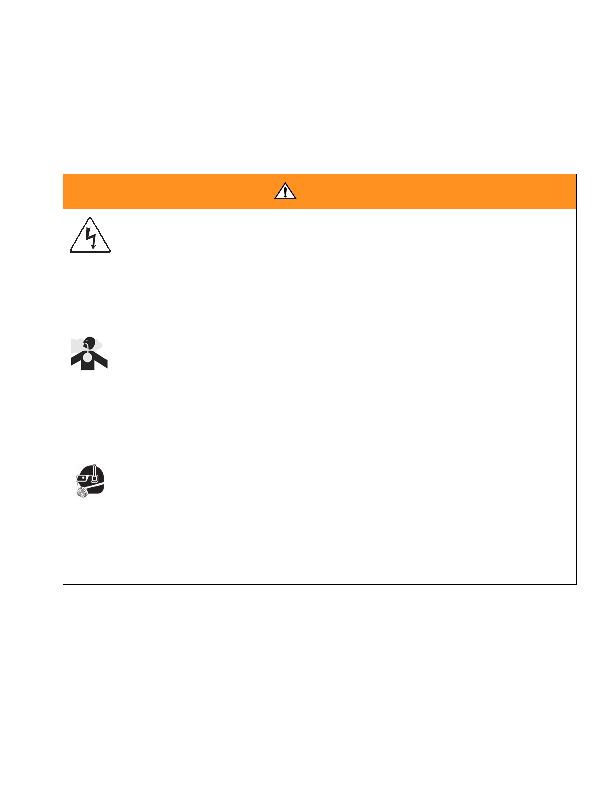
ELECTRIC SHOCK HAZARD
This equipment must be grounded. Improper grounding, setup, or usage of the system can
cause electric shock.
• Turn off and disconnect power at main switch before disconnecting any cables and before
servicing equipment.
• Connect only to grounded power source.
• All electrical wiring must be done by a qualified electrician and comply with all local codes
and regulations.
TOXIC FLUID OR FUMES HAZARD
Toxic fluids or fumes can cause serious injury or death if splashed in the eyes or on skin,
inhaled, or swallowed.
• Read MSDSs to know the specific hazards of the fluids you are using.
• Store hazardous fluid in approved containers, and dispose of it according to applicable
guidelines.
• Always wear chemically impermeable gloves when spraying, dispensing, or cleaning
equipment.
PERSONAL PROTECTIVE EQUIPMENT
You must wear appropriate protective equipment when operating, servicing, or when in the
operating area of the equipment to help protect you from serious injury, including eye injury,
inhalation of toxic fumes, burns, and hearing loss. This equipment includes but is not limited
to:
• Protective eyewear
• Clothing and respirator as recommended by the fluid and solvent manufacturer
•Gloves
• Hearing protection
312062W 9
Page 10
Warnings
WARNING
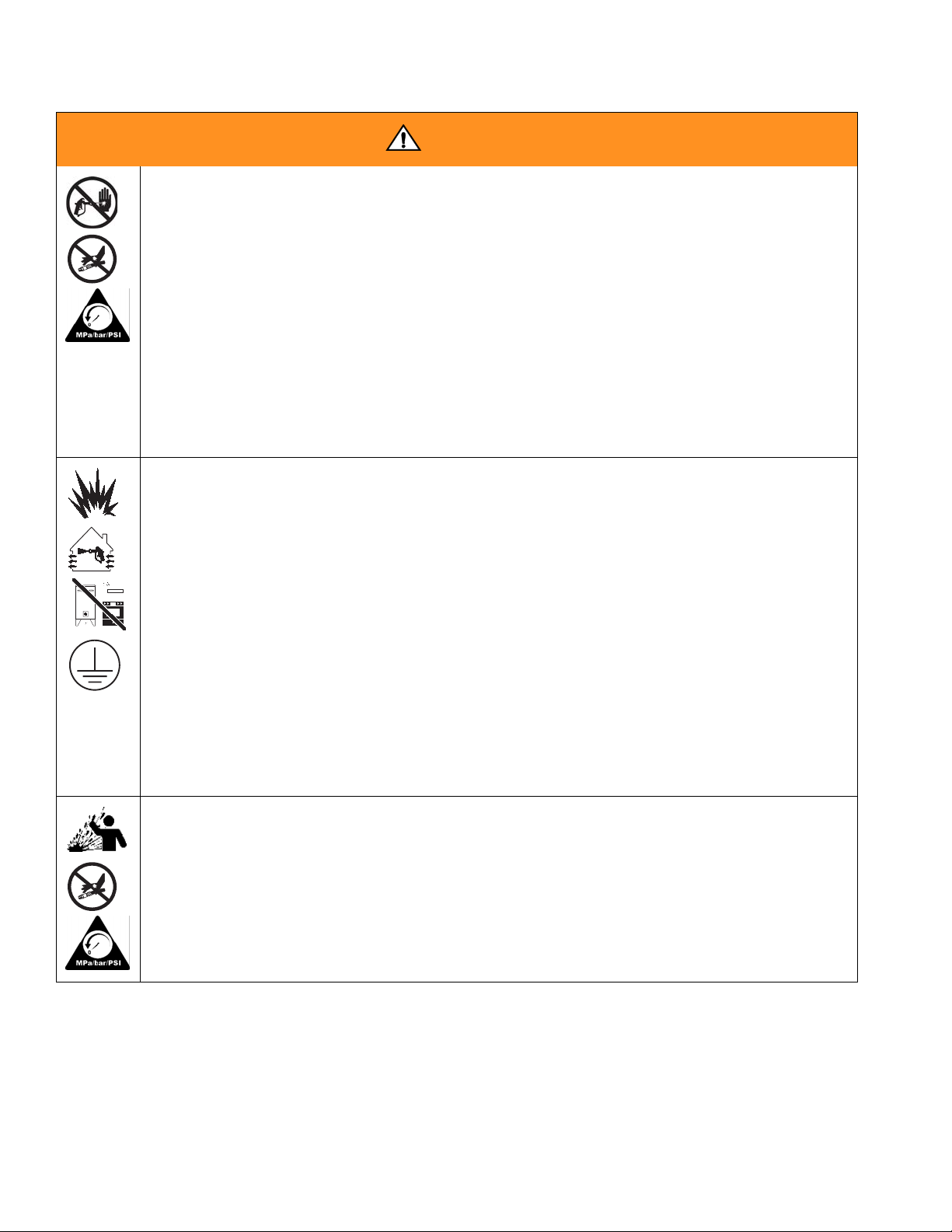
SKIN INJECTION HAZARD
High-pressure fluid from gun, hose leaks, or ruptured components will pierce skin. This may
look like just a cut, but it is a serious injury that can result in amputation. Get immediate
surgical treatment.
• Engage trigger lock when not spraying.
• Do not point gun at anyone or at any part of the body.
• Do not put your hand over the spray tip.
• Do not stop or deflect leaks with your hand, body, glove, or rag.
• Follow the Pressure Relief Procedure when you stop spraying and before cleaning,
checking, or servicing equipment.
• Tighten all fluid connections before operating the equipment.
• Check hoses and couplings daily. Replace worn or damaged parts immediately.
FIRE AND EXPLOSION HAZARD
Flammable fumes, such as solvent and paint fumes, in work area can ignite or explode. To
help prevent fire and explosion:
• Use equipment only in well ventilated area.
• Eliminate all ignition sources; such as pilot lights, cigarettes, portable electric lamps, and
plastic drop cloths (potential static arc).
• Keep work area free of debris, including solvent, rags and gasoline.
• Do not plug or unplug power cords, or turn power or light switches on or off when flammable fumes are present.
• Ground all equipment in the work area. See Grounding instructions.
• Use only grounded hoses.
• Hold gun firmly to side of grounded pail when triggering into pail.
• If there is static sparking or you feel a shock, stop operation immediately. Do not use
equipment until you identify and correct the problem.
• Keep a working fire extinguisher in the work area.
THERMAL EXPANSION HAZARD
Fluids subjected to heat in confined spaces, including hoses, can create a rapid rise in pressure due to the thermal expansion. Over-pressurization can result in equipment rupture and
serious injury.
• Open a valve to relieve the fluid expansion during heating.
• Replace hoses proactively at regular intervals based on your operating conditions.
10 312062W
Page 11
Warnings
WARNING
PRESSURIZED ALUMINUM PARTS HAZARD
Use of fluids that are incompatible with aluminum in pressurized equipment can cause serious chemical reaction and equipment rupture. Failure to follow this warning can result in
death, serious injury, or property damage.
• Do not use 1,1,1-trichloroethane, methylene chloride, other halogenated hydrocarbon solvents or fluids containing such solvents.
• Many other fluids may contain chemicals that can react with aluminum. Contact your
material supplier for compatibility.
EQUIPMENT MISUSE HAZARD
Misuse can cause death or serious injury.
• This equipment is for professional use only.
• Do not leave the work are while the equipment is energized or under pressure. Turn off all
equipment and follow the Pressure Relief Procedure in this manual when the equipment
is not in use.
• Do not operate the unit when fatigued or under the influence of drugs or alcohol.
• Do not exceed the maximum working pressure or temperature rating of the lowest rated
system component. See Technical Data in all equipment manuals.
• Use fluids and solvents that are compatible with equipment wetted parts. See Technical
Data in all equipment manuals. Read fluid and solvent manufacturer’s warnings. For complete information about your material, request MSDS forms from distributor or retailer.
• Check equipment daily. Repair or replace worn or damaged parts immediately with genuine manufacturer’s replacement parts only.
• Do not alter or modify equipment.
• Use equipment only for its intended purpose. Call your distributor for information.
• Route hoses and cables away from traffic areas, sharp edges, moving parts, and hot surfaces.
• Do not kink or over bend hoses or use hoses to pull equipment.
• Keep children and animals away from work area.
• Comply with all applicable safety regulations.
MOVING PARTS HAZARD
Moving parts can pinch or amputate fingers and other body parts.
• Keep clear of moving parts.
• Do not operate equipment with protective guards or covers removed.
• Pressurized equipment can start without warning. Before checking, moving, or servicing
equipment, follow the Pressure Relief Procedure in this manual. Disconnect power or
air supply.
BURN HAZARD
Equipment surfaces and fluid that’s heated can become very hot during operation. To avoid
severe burns, do not touch hot fluid or equipment. Wait until equipment/fluid has cooled completely.
312062W 11
Page 12
Important Two-Component Material Information
Important Two-Component Material Information
Isocyanate Conditions
Spraying or dispensing materials containing
isocyanates creates potentially harmful
mists, vapors, and atomized particulates.
Read material manufacturer’s warnings and
material MSDS to know specific hazards
and precautions related to isocyanates.
Prevent inhalation of isocyanate mists,
vapors, and atomized particulates by providing sufficient ventilation in the work area.
If sufficient ventilation is not available, a
supplied-air respirator is required for everyone in the work area.
To prevent contact with isocyanates, appropriate personal protective equipment,
including chemically impermeable gloves,
boots, aprons, and goggles, is also required
for everyone in the work area.
Keep Components A and B Separate
Cross-contamination can result in cured
material in fluid lines which could cause serious injury or damage equipment. To prevent
cross-contamination of the equipment’s wetted parts, never interchange component A
(isocyanate) and component B (resin) parts.
Moisture Sensitivity of Isocyanates
Isocyanates (ISO) are catalysts used in two
component foam and polyurea coatings. ISO
will react with moisture (such as humidity) to
form small, hard, abrasive crystals, which
become suspended in the fluid. Eventually a
film will form on the surface and the ISO will
begin to gel, increasing in viscosity. If used,
this partially cured ISO will reduce performance and the life of all wetted parts.
Material Self-ignition
To prevent exposing ISO to moisture:
Some materials may become self-igniting if
applied too thickly. Read material manufacturer’s warnings and material MSDS.
12 312062W
• Always use a sealed container with a des-
• Keep the ISO lube pump reservoir (if
The amount of film formation and rate of
crystallization varies depending on the
blend of ISO, the humidity, and the temperature.
iccant dryer in the vent, or a nitrogen atmosphere. Never store ISO in an open
container.
installed) filled with Graco Throat Seal Liquid (TSL), Part 206995. The lubricant creates a barrier between the ISO and the
atmosphere.
Page 13

Important Two-Component Material Information
• Use moisture-proof hoses specifically
designed for ISO, such as those supplied
with your system.
• Never use reclaimed solvents, which may
contain moisture. Always keep solvent containers closed when not in use.
• Never use solvent on one side if it has
been contaminated from the other side.
• Always lubricate threaded parts with ISO
pump oil or grease when reassembling.
Foam Resins with 245 fa Blowing Agents
Some foam blowing agents will froth at temperatures above 90°F (33°C) when not under
pressure, especially if agitated. To reduce
frothing, minimize preheating in a circulation
system.
Changing Materials
• When changing materials, flush the equipment multiple times to ensure it is thoroughly clean.
• Always clean the fluid inlet strainers after
flushing.
• Check with your material manufacturer for
chemical compatibility.
• Most materials use ISO on the A side, but
some use ISO on the B side.
• Epoxies often have amines on the B (hardener) side. Polyureas often have amines on
the B (resin) side.
312062W 13
Page 14
Typical Installation, with circulation
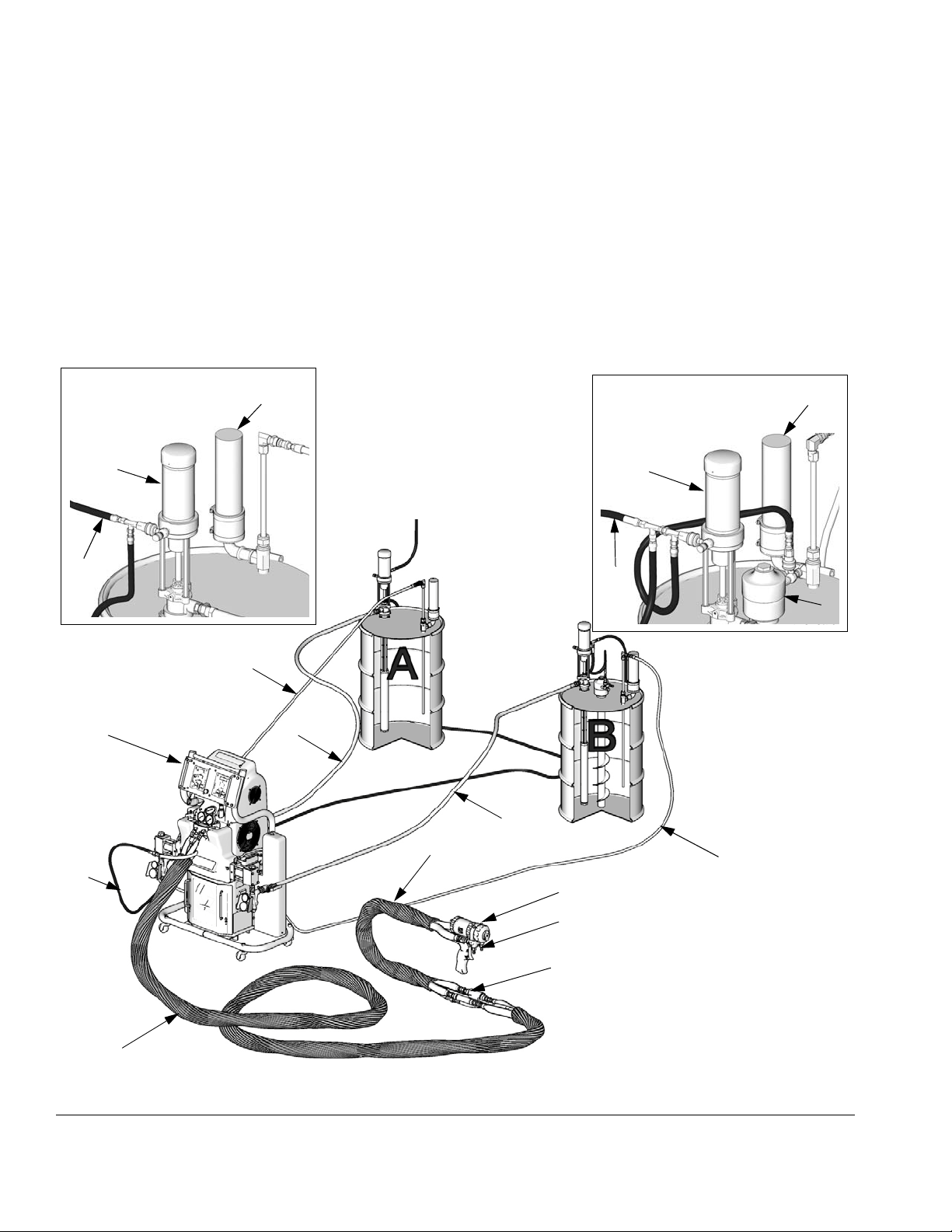
Key for FIG. 1
Typical Installation, with circulation
A Reactor Proportioner
B Heated Hose
C Fluid Temperature Sensor (FTS)
D Heated Whip Hose
E Fusion Spray Gun
F Gun Air Supply Hose
A Side Supply Detail
K
G
ti7820a 2
M
G Feed Pump Air Supply Lines
J Fluid Supply Lines
K Feed Pumps
L Agitator
M Desiccant Dryer
P Gun Fluid Manifold (part of gun)
R Circulation Lines
B Side Supply Detail
K
G
M
L
ti7820a 3
R
A
F
B
J
FIG. 1: Typical Installation, with circulation
J
D
R
E
P
C*
* Shown exposed for clarity.
Wrap with tape during operation.
ti10000a
14 312062W
Page 15
Typical Installation, without circulation
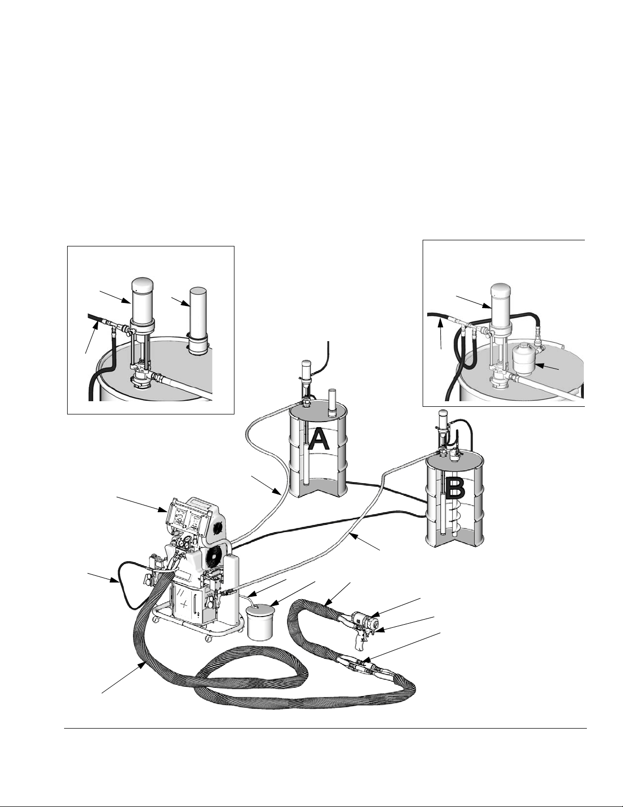
Typical Installation, without circulation
Key for FIG. 2
A Reactor Proportioner
B Heated Hose
C Fluid Temperature Sensor (FTS)
D Heated Whip Hose
E Fusion Spray Gun
F Gun Air Supply Hose
G Feed Pump Air Supply Lines
A Side Supply Detail
K
G
M
ti7821a 2
H Waste Containers
J Fluid Supply Lines
K Feed Pumps
L Agitator
M Desiccant Dryer
N Bleed Lines
P Gun Fluid Manifold (part of gun)
B Side Supply Detail
K
G
L
ti7821a 3
J
A
F
B
N
FIG. 2: Typical Installation, without circulation
J
H
D
E
P
C*
* Shown exposed for clarity.
Wrap with tape during operation.
ti10001a
312062W 15
Page 16

Component Identification
Key for FIG. 3
BA Component A Pressure Relief Outlet
BB Component B Pressure Relief Outlet
EC Heated Hose Electrical Connector
EM Electric Motor, Fan, and Belt Drive (behind shroud)
FA Component A Fluid Manifold Inlet (on left side of manifold
block)
FB Component B Fluid Manifold Inlet
FH Fluid Heater (behind shroud)
FM Reactor Fluid Manifold
FP Feed Inlet Pressure Gauge
FS Feed Inlet Strainer
FT Feed Inlet Temperature Gauge
FV Fluid Inlet Valve (B side shown)
GA Component A Outlet Pressure Gauge
GB Component B Outlet Pressure Gauge
HA Component A Hose Connection
HB Component B Hose Connection
HC Hydraulic Pressure Control
HP Hydraulic Pressure Gauge
LR ISO Lube Pump Reservoir
MC Motor Control Display
MP Main Power Switch
OP Overpressure Rupture Disk Assembly (on rear of A and B
pumps)
PA Component A Pump
PB Component B Pump
RS Red Stop Button
SA Component A PRESSURE RELIEF/SPRAY Valve
SB Component B PRESSURE RELIEF/SPRAY Valve
SC Fluid Temperature Sensor Cable
SN Serial Number Plate (one inside cabinet, one on right side
of cabinet)
SR Electrical Cord Strain Relief
TA Component A Pressure Transducer (behind gauge GA)
TB Component B Pressure Transducer (behind gauge GB)
TC Temperature Control Display
TD Oil Cooler
Component Identification
16 312062W
Page 17

Component Identification
MC
PA
FT
FP
HP
EC
FM
TC
RS
HC
EM
FH
OP
PB
SC
LR
SN
Detail of Reactor Fluid Manifold
(shroud removed for clarity)
TA
SA
FA
BA
HA
GA
HB
GB
BB
ti9880a
TB
FV
MP
FS
SR
TI9830a
Detail of Serial No.
Plate (inside cabinet)
SB
FB
ti7823a
SN
FIG. 3: Component Identification (H40 15.3 kW Model Shown)
312062W 17
Page 18

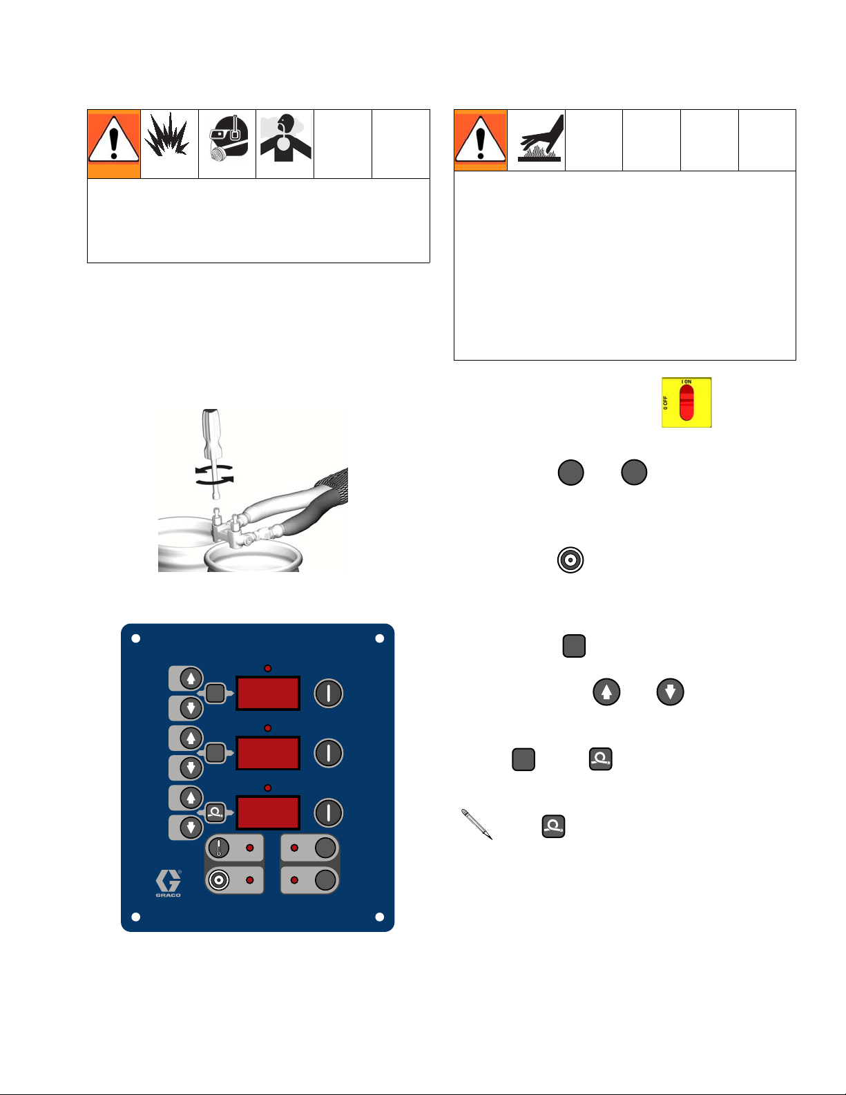
Temperature Controls and Indicators
Temperature Controls and Indicators
NOTICE
To prevent damage to the softkey buttons, do
not press the buttons with sharp objects
such as pens, plastic cards, or fingernails.
Zone A Arrow Keys
Zone B Arrow Keys
Hose Zone Arrow Keys
Actual Temperature
Key
Heater Power Indicators
A
B
Heater Displays
°
F
°
C
Heater A On/Off
Key
Heater B On/Off
Key
Hose Heater On/Off
Key
Temperature Scale
Keys
Target Temperature Key
FIG. 4. Temperature Controls and Indicators
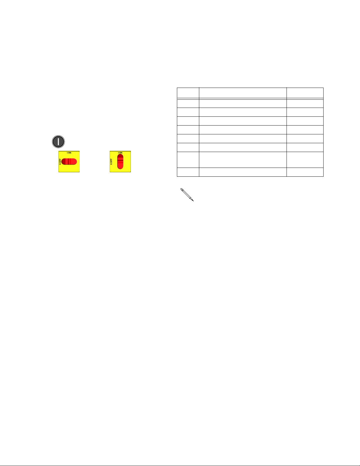
Main Power Switch
Located on right side of unit, page 17. Turns
Reactor power ON and OFF .
Does not turn heater zones or pumps on.
18 312062W
Red Stop Button
Located between temperature control panel
and motor control panel, page 17. Press
to shut off motor and heater zones
only. Use main power switch to shut off all
power to unit.
Page 19

Temperature Controls and Indicators
Actual Temperature Key/LED
Press to display actual temperature.
Press and hold to display electrical cur-
rent.
Target Temperature Key/LED
Press to display target temperature.
Press and hold to display heater control
circuit board temperature.
Temperature Scale
Heater Zone On/Off Keys/LEDs
Press to turn heater zones on and off.
Also clears heater zone diagnostic codes, see
page 42.
LEDs flash when heater zones are on.
The duration of each flash shows the
extent that the heater is turned on.
Temperature Arrow Keys
Press , then press or to
adjust temperature settings in 1 degree increments.
Keys/LEDs
Press or to change temperature
scale.
°
F
°
C
Temperature Displays
Show actual temperature or target temperature of heater zones, depending on selected
mode. Defaults to actual at startup. Range is
32-190°F (0-88°C) for A and B, 32-180°F
(0-82°C) for hose.
312062W 19
Page 20

Temperature Controls and Indicators
Circuit Breakers
Located inside Reactor cabinet.
Ref. Size Component
CB1 50 A Hose/Transformer Secondary
CB2 40 A Transformer Primary
CB3 25, 40, or
50 A*
CB4 25, 40, or
50 A*
CB5 20 or 30 A* Motor/Pumps
Heater A
Heater B
* Depending on model.
CB1
CB2
CB3
For wiring and cabling, see repair manual 312063.
CB4
CB5
ti9884a
20 312062W
Page 21

Motor Controls and Indicators
Motor Controls and Indicators
NOTICE
To prevent damage to the softkey buttons, do
not press the buttons with sharp objects
such as pens, plastic cards, or fingernails.
Arrow Keys
Motor ON/OFF Key
PARK Key
Pressure Key
Cycle Count Key
FIG. 5. Motor Controls and Indicators
Pressure/Cycle Display
ON / OFF
PARK
PSI/BAR Keys
PSI
BAR
Motor ON/OFF Key/LED
Press to turn motor ON and OFF. Also
PSI/BAR Keys/LEDs
Press or to change pressure scale.
PSI
BAR
clears some motor control diagnostic codes,
see page 43.
Pressure Key/LED
PARK Key/LED
Press at end of day to cycle component
A pump to home position, submerging displacement rod. Trigger gun until pump stops.
Once parked, motor will automatically shut off.
312062W 21
Press to display fluid pressure.
If pressures are imbalanced, display
shows higher of two pressures.
Page 22

Spray Adjustments
Cycle Count Key/LED
Press to display cycle count.
To clear counter, press and hold
for 3 sec.
Hydraulic Pressure Control Knob
Use to adjust hydraulic pressure available to
the hydraulic drive system. Turn knob (HC)
clockwise to increase pressure and counterclockwise to decrease pressure. Use hydraulic
pressure gauge (HP, page 17) to view hydraulic pressure.
Spray Adjustments
Flow rate, atomization, and amount of overspray are affected by four variables.
• Fluid pressure setting. Too little pressure
results in an uneven pattern, coarse droplet
size, low flow, and poor mixing. Too much
pressure results in excessive overspray,
high flow rates, difficult control, and excessive wear.
• Fluid temperature. Similar effects to fluid
pressure setting. The A and B temperatures can be offset to help balance the fluid
pressure.
• Mix chamber size. Choice of mix chamber
is based on desired flow rate and fluid viscosity.
+-
ti7731a ti7732a
Component A and B outlet pressures
will be higher than the hydraulic set
pressure, depending on the model (see
Pressure Ratio data; Systems, page 3).
Component A and B pressure may be
viewed on the pressure gauges (GA,
GB), or the higher of the two pressures
may be displayed on the motor control
IG
panel (MC). See F
. 3, page 17.
Motor Control Arrow Keys
Use or to:
• Adjust pressure imbalance settings, page
33.
• Clean-off air adjustment. Too little
clean-off air results in droplets building up
on the front of the nozzle, and no pattern
containment to control overspray. Too
much clean-off air results in air-assisted
atomization and excessive overspray.
• Adjust standby settings, page 37.
22 312062W
Page 23

Setup
Setup
NOTICE
Proper system setup, start up, and shutdown
procedures are critical to electrical equipment reliability. The following procedures
ensure steady voltage. Failure to follow these
procedures will cause voltage fluctuations
that can damage electrical equipment and
void the warranty.
1. Locate Reactor
a. Locate Reactor on a level surface. See
Dimensions, page 48, for clearance
and mounting hole dimensions.
b. Do not expose Reactor to rain.
NOTICE
To prevent damage from tipping over and falling, proper care needs to be taken when lifting the Reactor. Bolt Reactor to original
shipping pallet, to keep stable, before lifting.
2. General equipment guidelines
• Determine the correct size generator.
Using the correct size generator and proper
air compressor will enable the proportioner
to run at a nearly constant RPM. Failure to
do so will cause voltage fluctuations that
can damage electrical equipment. Ensure
the generator matches the voltage and
phase of the proportioner.
Use the following procedure to determine
the correct size generator.
a. List system components that use peak
load requirements in watts.
b. Add the wattage required by the system
components.
c. Perform the following equation:
Total watts x 1.25 = kVA (kilovolt-amperes)
c. Use the casters to move Reactor to a
fixed location, or bolt to shipping pallet
and move with forklift.
d. To mount on a truck bed or trailer,
remove casters and bolt directly to truck
or trailer bed. See page 48.
d. Select a generator size that is equal to
or greater than the determined kVA.
• Use proportioner power cords that meet or
exceed the requirements listed in Table 2.
Failure to do so will cause voltage fluctuations that can damage electrical equipment.
• Use an air compressor with constant speed
head unloading devices. Direct online air
compressors that start and stop during a
job will cause voltage fluctuations that can
damage electrical equipment.
312062W 23
Page 24

Setup
• Maintain and inspect the generator, air
compressor, and other equipment per the
manufacturer recommendations to avoid
an unexpected shutdown. Unexpected
equipment shutdown will cause voltage
fluctuations that can damage electrical
equipment.
• Use a wall power supply with enough current to meet system requirements. Failure
to do so will cause voltage fluctuations that
can damage electrical equipment.
3. Electrical requirements
See Table 1.
Installing this equipment requires access to
parts which may cause electric shock or
other serious injury if work is not performed
properly. Have a qualified electrician connect
power and ground to main power switch terminals, see page 25. Be sure your installation complies with all National, State and
Local safety and fire codes.
Table 1
: Electrical Requirements
(kW/Full Load Amps)
Full
Load
Voltage
Part Model
253407 H-40 230V (3) 95 31,700
253408 H-40 400V (3) 52 31,700
255400 H-25 230V (1) 69 15,960
255401 H-25 230V (3) 46 15,960
255402 H-25 400V (3) 35 15,960
255403 HXP2 230V (1) 100 23,260
255404 HXP2 230V (3) 59 23,260
255405 HXP2 400V (3) 35 23,260
255406 H-25 230V (1) 100 23,260
255407 H-25 230V (3) 59 23,260
255408 H-25 400V (3) 35 23,260
253725 H-50 230V (1) 100 23,100
253726 H-50 230V (3) 71 26,600
253727 H-50 400V (3) 41 26,600
256505 H-50 230V (3) 95 31,700
256506 H-50 400V (3) 52 31,700
(phase)
Peak
Amps*
System
Watts**
* Full load amps with all devices operating at
maximum capabilities. Fuse requirements at
various flow rates and mix chamber sizes may
be less.
Table 1
: Electrical Requirements
(kW/Full Load Amps)
Full
Load
Voltage
Part Model
253400 H-40 230V (1) 100 23,100
253401 H-40 230V (3) 71 26,600
253402 H-40 400V (3) 41 26,600
253403 H-XP3 230V (1) 100 23,100
253404 H-XP3 230V (3) 95 31,700
253405 H-XP3 400V (3) 52 31,700
(phase)
Peak
Amps*
System
Watts**
** Total system watts, based on maximum
hose length for each unit:
• Parts 255400 through 255408, 310 ft (94.6
m) maximum heated hose length, including
whip hose.
• Parts 253400 through 253408, 410 ft (125
m) maximum heated hose length, including
whip hose.
24 312062W
Page 25

Setup
4. Connect electrical cord
Power cord is not supplied. See Table 2.
Table 2: Power Cord Requirements
Cord Specification
Part Model
253400 H-40 4 (21.2), 2 wire + ground
253401 H-40 4 (21.2), 3 wire + ground
253402 H-40 8 (8.4), 4 wire + ground
253403 H-XP3 4 (21.2), 2 wire + ground
253404 H-XP3 4 (21.2), 3 wire + ground
253405 H-XP3 6 (13.3), 4 wire + ground
253407 H-40 4 (21.2), 3 wire + ground
253408 H-40 6 (13.3), 4 wire + ground
255400 H-25 4 (21.2), 2 wire + ground
255401 H-25 8 (8.4), 3 wire + ground
255402 H-25 8 (8.4), 4 wire + ground
255403 H-XP2 4 (21.2), 2 wire + ground
255404 H-XP2 6 (13.3), 3 wire + ground
255405 H-XP2 8 (8.4), 4 wire + ground
255406 H-25 4 (21.2), 2 wire + ground
255407 H-25 6 (13.3), 3 wire + ground
255408 H-25 8 (8.4), 4 wire + ground
253725 H-50 4 (21.2), 2 wire + ground
253726 H-50 4 (21.2), 3 wire + ground
253727 H-50 8 (8.4), 4 wire + ground
256505 H-50 4 (21.2), 3 wire + ground
256506 H-50 6 (13.3), 4 wire + ground
AWG (mm2)
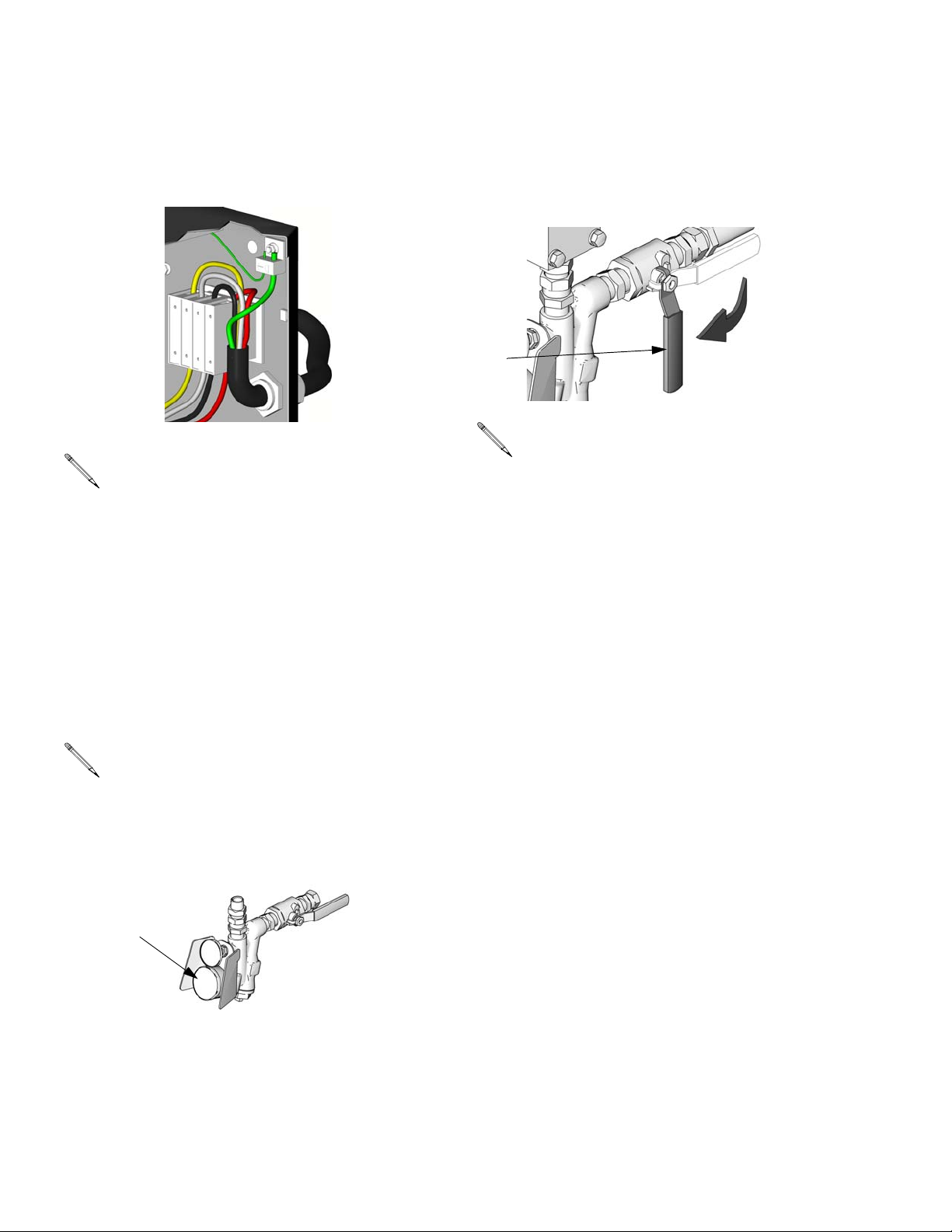
a. 230V, 1 phase: Using 5/32 or 4 mm hex
allen wrench, connect two power leads
to L1 and L2. Connect green to ground
(GND).
GND
L1
L2
ti2515b
b. 230V, 3 phase: Using 5/32 or 4 mm hex
allen wrench, connect three power
leads to L1, L2, and L3. Connect green
to ground (GND).
GND
L1
L2
L3
ti3248b
312062W 25
Page 26
Setup
c. 400V, 3 phase: Using 5/32 or 4 mm hex
allen wrench, connect three power
leads to L1, L2, and L3. Connect neutral
to N. Connect green to ground (GND).
GND
L1
L3
L2
N
ti2725a
Some 3-phase models utilize a 3-phase
motor. The motor must rotate counterclockwise when viewed from shaft end.
To reverse rotation, disconnect power
and reverse power leads L1 and L2.
c. Install agitator (L) in component B drum,
if necessary.
d. Ensure A and B inlet valves (FV) are
closed.
FV
ti9883a
Supply hoses from feed pumps should
be 3/4 in. (19 mm) ID.
5. Connect feed pumps
a. Install feed pumps (K) in component A
and B supply drums. See FIG. 1 and
FIG. 2, pages 14 and 15.
A minimum feed pressure of 50 psi
(0.35 MPa, 3.5 bar) is required at both
feed inlet pressure gauges (FP). Maximum feed pressure is 250 psi (1.75
MPa, 17.5 bar). Maintain A and B feed
pressures within 10% of each other.
FP
ti10006a
b. Seal component A drum and use desic-
cant dryer (M) in vent.
26 312062W
Page 27
Setup
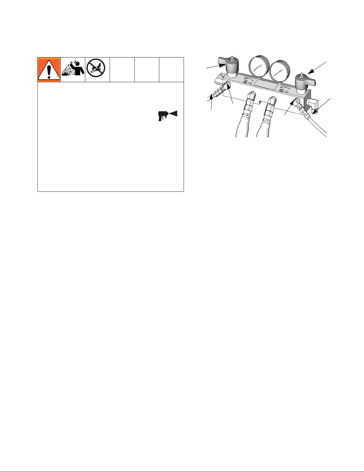
6. Connect pressure relief lines
Do not install shutoffs downstream of the
PRESSURE RELIEF/SPRAY valve outlets
(BA, BB). The valves function as overpres-
sure relief valves when set to SPRAY .
Lines must be open so valves can automatically relieve pressure when machine is operating.
SA
SB
R
R
BA
BB
ti9880a
If circulating fluid back to the supply drums,
use high pressure hose rated to withstand
the maximum working pressure of this
equipment.
a. Recommended: Connect high pressure
hose (R) to relief fittings (BA, BB) of
both PRESSURE RELIEF/SPRAY
valves, Route hose back to component
A and B drums. See FIG. 1, page 14.
b. Alternately: Secure supplied bleed
tubes (N) in grounded, sealed waste
containers (H). See FIG. 2, page 15.
7. Install Fluid Temperature Sensor (FTS)
The Fluid Temperature Sensor (FTS) is supplied. Install FTS between main hose and whip
hose. See Heated Hose manual 309572 for
instructions.
312062W 27
Page 28

Setup
8. Connect heated hose
See Heated Hose manual 309572 for
detailed instructions on connecting
heated hoses.
The fluid temperature sensor (C) and
whip hose (D) must be used with
heated hose, see page 27. Hose
length, including whip hose, must be 60
ft (18.3 m) minimum.
a. Turn main power OFF .
b. Assemble heated hose sections, FTS,
and whip hose.
d. Connect cables (Y). Connect electrical
connectors (V). Be sure cables have
slack when hose bends. Wrap cable
and electrical connections with electrical tape.
Y
V
ti9881a
9. Close gun fluid manifold valves A and B
c. Connect A and B hoses to A and B out-
lets on Reactor fluid manifold (FM).
Hoses are color coded: red for component A (ISO), blue for component B
(RES). Fittings are sized to prevent connection errors.
FM
N
A
P
B
ti9878a
Manifold hose adapters (N, P) allow use
of 1/4 in. and 3/8 in. ID fluid hoses. To
use 1/2 in. (13 mm) ID fluid hoses,
remove adapters from fluid manifold
and install as needed to connect whip
hose.
ti2411a
10.Connect whip hose to gun fluid manifold
Do not connect manifold to gun.
ti2417a
11. Pressure check hose
See hose manual. Pressure check for leaks. If
no leaks, wrap hose and electrical connections
to protect from damage.
28 312062W
Page 29
Setup
12.Ground system
a.
Reactor:
is grounded through power
cord. See page 25.
Spray gun:
b.
connect whip hose ground
wire to FTS, page 27. Do not disconnect wire or spray without whip hose.
c.
Fluid supply containers:
local code.
d.
Object being sprayed:
code.
e.
Solvent pails used when flushing:
your local code. Use only metal pails,
which are conductive, placed on a
grounded surface. Do not place pail on
a nonconductive surface, such as paper
or cardboard, which interrupts grounding continuity
follow your
follow your local
follow
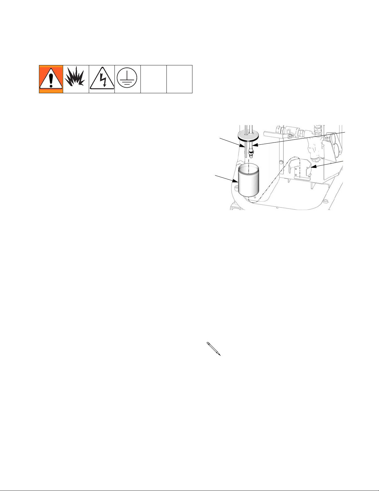
14.Lubrication system setup
Component A (ISO) Pump: Fill ISO lube
reservoir (LR) with Graco Throat Seal Liquid (TSL), Part 206995 (supplied).
a. Lift the lubricant reservoir (LR) out of
the bracket (RB) and remove the container from the cap.
RT
LR
b. Fill with fresh lubricant. Thread the res-
ervoir onto the cap assembly and place
it in the bracket (RB).
c. Push the larger diameter supply tube
(ST) approximately 1/3 of the way into
the reservoir.
ST
RB
ti9911a
f.
To maintain grounding continuity when
flushing or relieving pressure,
hold a
metal part of spray gun firmly to the side
metal
of a grounded
pail, then trigger
gun.
d. Push the smaller diameter return tube
(RT) into the reservoir until it reaches
the bottom.
Important: The return tube (RT) must
reach the bottom of the reservoir, to
13.Check hydraulic fluid level
ensure that isocyanate crystals will settle to the bottom and not be siphoned
Hydraulic reservoir is filled at the factory.
Check fluid level before operating the first
into the supply tube (ST) and returned
to the pump.
time, and weekly thereafter. See Mainte-
nance, page 44.
e. The lubrication system is ready for
operation. No priming is required.
312062W 29
Page 30
Startup
NOTICE
Proper system setup, startup, and shutdown
procedures are critical to electrical equipment reliability. The following procedures
ensure steady voltage. Failure to follow
these procedures will cause voltage fluctuations that can damage electrical equipment
and void the warranty.
Startup
a. Check that all Setup steps are com-
plete.
b. Check that inlet screens are clean
before daily startup, page 45.
c. Check level and condition of ISO lube
daily, page 44.
d. Turn on component B agitator, if used.
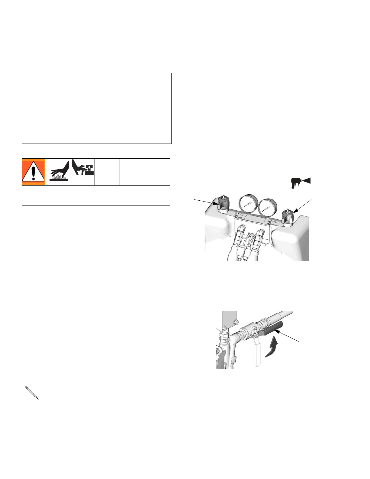
e. Turn both PRESSURE RELIEF/SPRAY
Do not operate Reactor without all covers
and shrouds in place.
1. Check generator fuel level.
Running out of fuel will cause voltage fluctuations that can damage electrical equipment.
2. Ensure the main breaker on the generator is in the off position.
3. Start the generator. Allow it to reach full
operating temperature.
4. Close the bleed valve on the air compressor.
5. Switch on the air compressor starter
and air dryer, if included.
6. Turn on power to the Reactor.
7. Load fluid with feed pumps
valves (SA, SB) to SPRAY .
SA
f. Start feed pumps.
g. Open fluid inlet valves (FV). Check for
leaks.
FV
ti10002a
SB
ti9877a
The Reactor is tested with oil at the factory. Flush out the oil with a compatible
solvent before spraying. See page 47.
30 312062W
Page 31
Startup
Do not mix components A and B during
startup. Always provide two grounded waste
containers to keep component A and component B fluids separate.
h. Use feed pumps to load system. Hold
gun fluid manifold over two grounded
waste containers. Open fluid valves A
and B until clean, air-free fluid comes
from valves. Close valves.
ti2484a
This equipment is used with heated fluid,
which can cause equipment surfaces to
become very hot. To avoid severe burns:
• Do not touch hot fluid or equipment.
• Allow equipment to cool completely
before touching it.
• Wear gloves if fluid temperature exceeds
110°F (43°C).
a. Turn main power ON .
b. Press or to change tem-
°
F
°
C
perature scale.
c. Press to display target tempera-
8. Set temperatures
A
B
°
F
°
C
Temperature Controls and Indicators, see
page 18
tures.
d. To set heat zone target tempera-
A
ture, press or until display
shows desired temperature. Repeat for
and zones.
B
For zone only, if FTS is discon-
nected at startup, display will show hose
current (0A). See step j, page 32.
312062W 31
Page 32

e. Press to display actual tempera-
tures.
Do not turn on hose heat without fluid in
hoses.
f. Turn on heat zone by pressing
. Preheat hose (15-60 min). Indi-
Startup
j. Manual current control mode only:
When in manual current control mode, monitor hose temperature with thermometer.
Install per instructions below. Thermometer
reading must not exceed 160°F (71°C).
Never leave machine unattended when in
manual current control mode.
If FTS is disconnected or display shows
diagnostic code E04, turn main power
cator will flash very slowly when fluid
reaches target temperature. Display
shows actual fluid temperature in hose
near FTS.
Thermal expansion can cause overpressurization, resulting in equipment rupture and
serious injury, including fluid injection. Do not
pressurize system when preheating hose.
g. Turn on and heat zones by
A
B
pressing for each zone.
switch OFF then ON to
clear diagnostic code and enter manual
current control mode. display will
show current to hose. Current is not limited by target temperature.
Press or to adjust current
setting.
To prevent overheating, install hose
thermometer close to gun end, within
operator view. Insert thermometer
through foam cover of A component
hose so stem is next to inner tube.
Thermometer reading will be about
20°F less than actual fluid temperature.
If thermometer reading exceeds 160°F
(71°C), reduce current with key.
h. Hold to view electrical currents for
each zone.
i. Hold to view heater control circuit
board temperature.
32 312062W
Page 33

Startup
9. Set pressure
ON / OFF
PARK
PSI
BAR
Motor Controls and Indicators, see
page 21
a. Press to display the pressure
Check the pressure of each proportioning pump using the component A and B
gauges. The pressures should be
approximately equal and must remain
fixed.
d. To display cycle count, press .
To clear counter, press and hold
for 3 sec.
e. Press or to change pres-
PSI
BAR
sure scale.
10.Change pressure imbalance setting
(optional)
reading.
b. Press motor . Motor and pumps
start. Display shows system pressure.
Motor must rotate counterclockwise
when viewed from shaft end. See Con-
nect electrical cord, page 25.
c. Adjust hydraulic pressure control until
display shows desired fluid pressure.
+-
ti7731a ti7732a
If display pressure is greater than
desired pressure, reduce the hydraulic
pressure and trigger gun to reduce
pressure.
The pressure imbalance function (status code
24, page 43) detects conditions that can cause
off-ratio spray, such as loss of feed pressure/supply, pump seal failure, clogged fluid
inlet filter, or a fluid leak.
Code 24 (pressure imbalance) is set to
an alarm as the default. To change to a
warning, see Reactor Repair-Parts
manual 312063.
The pressure imbalance default is factory-set
at 500 psi (3.5 MPa, 35 bar). For tighter ratio
error detection, select a lower value. For
looser detection or to avoid nuisance alarms,
select a higher value.
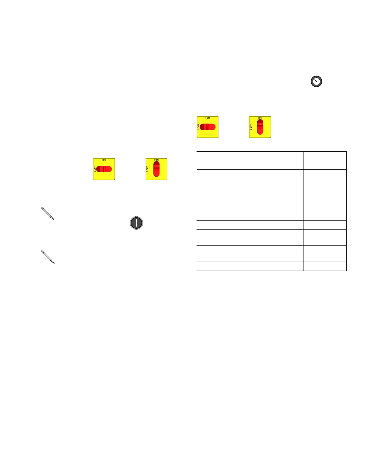
a. Turn main power switch OFF .
312062W 33
Page 34

Startup
b. Press and hold or , then turn
PSI
BAR
main power switch ON . Display
will read dP500 for psi or dP_35 for bar.
c. Press or to select desired
pressure differential (100-999 in increments of 100 psi, or 7-70 in increments
ABLE
of 7 bar). See T
Table 3: Available Pressure Imbalance Settings
3.
PSI BAR PSI BAR
100 7 600 42
200 14 700 49
300 21 800 56
400 28 900 63
*500 *35 999 69
* Factory default setting.
d. Turn main power switch OFF to
save changes.
34 312062W
Page 35

Spraying
Spraying
1. Engage gun piston safety lock.
4. Set PRESSURE RELIEF/SPRAY valves
(SA, SB) to SPRAY .
SA
SB
ti9877a
ti2409a
2. Close gun fluid manifold valves A and B.
ti2728a
3. Attach gun fluid manifold. Connect gun air
line. Open air line valve.
5. Check that heat zones are on and temperatures are on target, page 31.
6. Press motor to start motor and
pumps.
7. Check fluid pressure display and adjust as
necessary.
8. Check fluid pressure gauges (GA, GB) to
ensure proper pressure balance. If imbalanced, reduce pressure of higher component by slightly turning PRESSURE
RELIEF/SPRAY valve for that component
toward PRESSURE RELIEF/CIRCULA-
TION , until gauges show balanced
pressures.
GA
GB
In this example, B side
pressure is higher, so
use the B
ti2543a
312062W 35
balance pressures.
ti9877a
side valve to
Page 36

9. Open gun fluid manifold valves A and B. 10. Disengage gun piston safety lock.
11.Test spray onto cardboard. Adjust pressure
ti2414a
and temperature to get desired results.
12.Equipment is ready to spray.
Spraying
ti2410a
On impingement guns, never open fluid
manifold valves or trigger gun if pressures are imbalanced.
If you stop spraying for a period of time,
the unit will enter standby (if enabled).
See page 37.
36 312062W
Page 37

Standby
Standby
If you stop spraying for a period of time, the
unit will enter standby by shutting down the
electric motor and hydraulic pump, to reduce
equipment wear and minimize heat buildup.
The ON/OFF LED and the pressure/cycle display on the motor control panel will flash when
in standby.
The , , and heat zones
will not be shut off in standby.
To restart, spray off target for 2 sec. The system will sense the pressure drop and the motor
will ramp up to full speed in a few seconds.
This feature is disabled from the factory.
A
B
To activate or disable standby, adjust DIP
switch #3 on the motor control board. See
Reactor Repair-Parts manual 312063.
The idle time before entering standby is
user-settable as follows:
1. Turn main power switch OFF .
2. Press and hold , then turn main power
switch ON .
3. Press or to select desired timer
setting (5-20, in 5 minute increments). This
sets the length of inactive time before the
unit will enter standby.
4. Turn main power switch OFF to
save changes.
312062W 37
Page 38

Shutdown
Shutdown
NOTICE
Proper system setup, startup, and shutdown
procedures are critical to electrical equipment reliability. The following procedures
ensure steady voltage. Failure to follow
these procedures will cause voltage fluctuations that can damage electrical equipment
and void the warranty.
1. Shut off , , and heat
zones.
2. Park pumps.
a. Press .
b. Trigger gun until pump A stops in the
retracted position and the pressure of
both pumps bleeds down.
A
B
9. Close both fluid supply valves (FV).
FV
ti9883a
10. Shut down feed pumps as required.
3. Turn main power OFF .
4. Relieve pressure, page 39.
5. Turn off the air compressor and air dryer, if
included.
6. Open air compressor bleed valve to relieve
pressure and remove water from tank.
7. Turn off the main breaker on the generator.
8. Allow generator dwell time, per manufacturer recommendations, prior to shutdown.
38 312062W
Page 39

Pressure Relief Procedure
Pressure Relief Procedure
5. Turn PRESSURE RELIEF/SPRAY valves
1. Relieve pressure in gun and perform gun
shutdown procedure. See gun manual.
2. Engage gun piston safety lock.
ti2409a
(SA, SB) to PRESSURE RELIEF/CIRCU-
LATION . Route fluid to waste containers or supply tanks. Ensure gauges drop to
0.
SA
SB
ti9879a
3. Close gun fluid manifold valves A and B.
ti2421a
4. Shut off feed pumps and agitator, if used.
6. Disconnect gun air line and remove gun
fluid manifold.
ti2554a
312062W 39
Page 40

Fluid Circulation
Fluid Circulation
Circulation Through Reactor
Do not circulate fluid containing a blowing
agent without consulting with your material
supplier regarding fluid temperature limits.
To circulate through gun manifold and preheat
hose, see page 41.
1. Follow Startup procedures, page 30.
Do not install shutoffs downstream of the
PRESSURE RELIEF/SPRAY valve outlets
(BA, BB). The valves function as overpres-
sure relief valves when set to SPRAY .
Lines must be open so valves can automatically relieve pressure when machine is operating.
2. See Typical Installation, with circulation,
page 14. Route circulation lines back to
respective component A or B supply drum.
Use hoses rated at the maximum working
pressure of this equipment. See Technical
Data, page 49.
3. Set PRESSURE RELIEF/SPRAY valves
(SA, SB) to PRESSURE RELIEF/CIRCU-
LATION .
SA
SB
ti9879a
4. Turn main power ON .
5. Set temperature targets, see page 31. Turn
on and heat zones by pressing
A
. Do not turn on heat zone
unless hoses are already loaded with fluid.
6. Press to display actual temperatures.
7. Before starting motor, reduce hydraulic
pressure to the minimum required to circu-
late fluid until and tempera-
tures reach targets.
B
A
B
-
ti7732a
8. Press motor to start motor and
pumps. Circulate fluid at lowest possible
pressure until temperatures reach targets.
9. Turn on heat zone by pressing .
40 312062W
Page 41

Fluid Circulation
10.Set PRESSURE RELIEF/SPRAY valves
(SA, SB) to SPRAY .
SA
SB
ti9877a
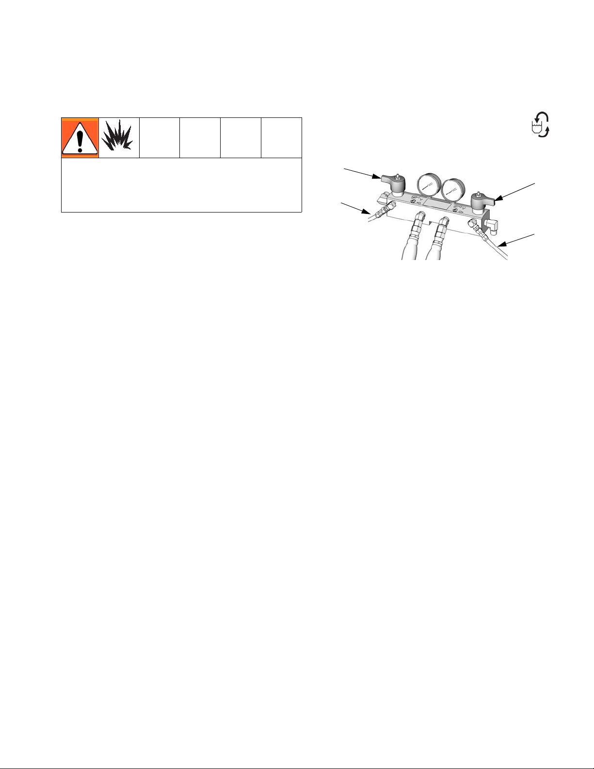
Circulation Through Gun Manifold
Do not circulate fluid containing a blowing
agent without consulting with your material
supplier regarding fluid temperature limits.
3. Follow Startup procedures, page 30.
4. Turn main power ON .
5. Set temperature targets, see page 31. Turn
on , , and heat zones by
A
B
pressing .
6. Press to display actual temperatures.
7. Before starting motor, reduce hydraulic
pressure to the minimum required to circu-
late fluid until and tempera-
A
B
tures reach targets.
Circulating fluid through the gun manifold
allows rapid preheating of hose.
1. Install gun fluid manifold (P) on Part
246362 accessory circulation kit (CK). Connect high pressure circulation lines (R) to
circulation manifold.
P
CK
R
ti2767a
2. Route circulation lines back to respective
component A or B supply drum. Use hoses
rated at the maximum working pressure of
this equipment. See Typical Installation,
without circulation, page 15.
-
ti7732a
8. Press motor to start motor and
pumps. Circulate fluid at lowest possible
pressure until temperatures reach targets.
312062W 41
Page 42
Diagnostic Codes
Temperature Control Diagnostic Codes
Temperature control diagnostic codes appear
on temperature display.
These alarms turn off heat. E99 clears automatically when communication is regained.
Codes E03 through E06 can be cleared by
pressing . For other codes, turn main
power OFF then ON to clear.
Code Code Name Alarm Zone
01 High fluid temperature Individual
02 High current Individual
03 No current Individual
04 FTS not connected Individual
05 Board over-temperature Individual
06 Loss of zone communication Individual
30 Momentary loss of communica-
99 Loss of display communication All
Diagnostic Codes
All
tion
See repair manual for corrective action.
For hose zone only, if FTS is disconnected at startup, display will show hose
current 0A.
42 312062W
Page 43
Diagnostic Codes
Motor Control Diagnostic Codes
Motor control diagnostic codes E21 through
E27 appear on pressure display.
There are two types of motor control codes:
alarms and warnings. Alarms take priority over
warnings.
See repair manual for corrective action.
Alarms
Alarms turn off the motor and heat zones. Turn
main power OFF then ON to
clear.
Alarms can also be cleared, except for
code 23, by pressing .
Code 24 (pressure imbalance) is set to
an alarm default of 500 psi (3.5 MPa, 35
bar). To change to a warning, see Reactor Repair-Parts manual 312063. To
change the default pressure imbalance
setting, see page 33.
Warnings
Reactor will continue to run. Press to
clear. A warning will not recur for a predetermined amount of time (varies for different
warnings), or until main power is turned OFF
then ON .
Code
No.
21 No transducer (component A) Alarm
22 No transducer (component B) Alarm
23 High pressure Alarm
24 Pressure imbalance Selectable;
27 High motor temperature Alarm
30 Momentary loss of communi-
cation
31 Pumpline switch failure/high
cycle rate
99 Loss of communication Alarm
Code Name Alarm or
Warning
see repair
manual
Alarm
Alarm
312062W 43
Page 44

Maintenance
Maintenance
• Inspect hydraulic and fluid lines for leaks
daily.
• Clean up all hydraulic leaks; identify and
repair cause of leak.
• Inspect fluid inlet strainer screens daily,
see below.
• Grease circulation valves weekly with
Fusion grease (117773).
ti9879a
• Inspect ISO lubricant level and condition
daily, see page 46. Refill or replace as
needed.
• Change break-in oil in a new unit after first
250 hours of operation or within 3 months,
whichever comes first. See Table 4 for recommended frequency of oil changes
Table 4: Frequency of Oil Changes
Ambient
Temperature
0 to 90°F
(-17 to 32°C)
Recommended
Frequency
1000 hours or 12
months, whichever
comes first
90°F and above
(32°C and above)
500 hours or 6 months,
whichever comes first
• Keep component A from exposure to moisture in atmosphere, to prevent crystallization.
• Clean gun mix chamber ports regularly.
See gun manual.
• Clean gun check valve screens regularly.
See gun manual.
• Check hydraulic fluid level weekly. Check
hydraulic fluid level on dipstick (DS). Fluid
level must be between indent marks (IM)
on dipstick. Refill as required with approved
hydraulic fluid; see Technical Data on
page 49 and the Approved Anti-Wear
(AW) Hydraulic Oils table in the Reactor
Repair-Parts manual 312063. If fluid is dark
in color, change fluid and filter.
DS
S
IM
ti10003a
ti7861a
• Use compressed air to prevent dust buildup
on control boards, fan, motor (under
shield), and hydraulic oil coolers.
• Keep vent holes on bottom of electrical
cabinet open.
44 312062W
Page 45

Maintenance
Fluid Inlet Strainer Screen
The inlet strainers filter out particles that can
plug the pump inlet check valves. Inspect the
screens daily as part of the startup routine, and
clean as required.
Use clean chemicals and follow proper storage, transfer, and operating procedures, to
minimize contamination of the A-side screen.
Clean the A-side screen only during
daily startup. This minimizes moisture
contamination by immediately flushing
out any isocyanate residue at the start
of dispensing operations.
5. Open the fluid inlet valve, ensure that there
are no leaks, and wipe the equipment
clean. Proceed with operation.
59d
59g*
59h
59j
59k
ti9886a
FIG. 6. Fluid Inlet Strainer
* See Reactor Repair-Parts manual 312063 for
fluid filter screen replacements.
1. Close the fluid inlet valve at the pump inlet
and shut off the appropriate feed pump.
This prevents material from being pumped
while cleaning the screen.
2. Place a container under the strainer manifold (59d) to catch fluid. Remove the
strainer plug (59j).
3. Remove the screen (59g) from the strainer
manifold. Thoroughly flush the screen with
compatible solvent and shake it dry.
Inspect the screen. If more than 25% of the
mesh is blocked, replace the screen.
Inspect the gasket (59h) and replace as
required.
4. Ensure the pipe plug (59k) is screwed into
the strainer plug (59j). Install the strainer
plug with the screen (59g) and gasket (59h)
in place and tighten. Do not overtighten.
Let the gasket make the seal.
312062W 45
Page 46
Maintenance
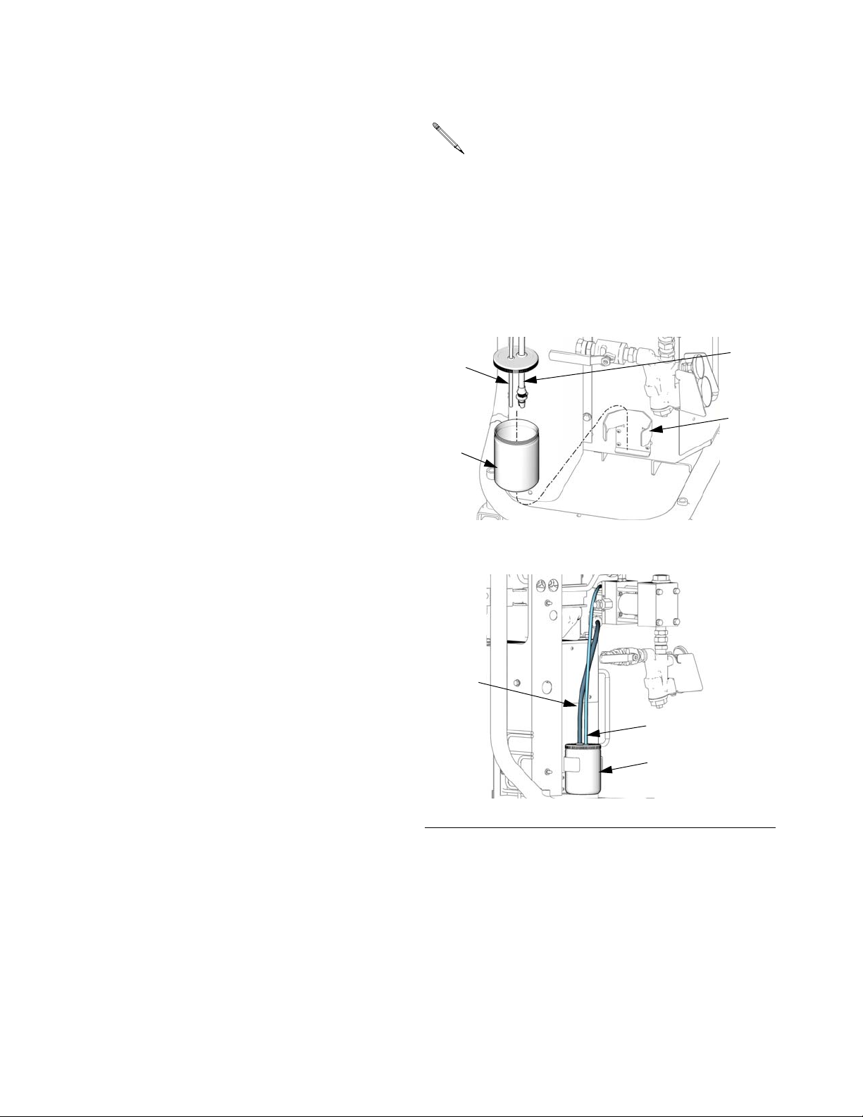
Pump Lubrication System
Check the condition of the ISO pump lubricant
daily. Change the lubricant if it becomes a gel,
its color darkens, or it becomes diluted with
isocyanate.
Gel formation is due to moisture absorption by
the pump lubricant. The interval between
changes depends on the environment in which
the equipment is operating. The pump lubrication system minimizes exposure to moisture,
but some contamination is still possible.
Lubricant discoloration is due to continual
seepage of small amounts of isocyanate past
the pump packings during operation. If the
packings are operating properly, lubricant
replacement due to discoloration should not be
necessary more often than every 3 or 4 weeks.
Important: The return tube (RT) must
reach the bottom of the reservoir, to
ensure that isocyanate crystals will settle to the bottom and not be siphoned
into the supply tube (ST) and returned
to the pump.
8. The lubrication system is ready for operation. No priming is required.
ST
RT
RB
LR
ti9911a
To change pump lubricant:
1. Relieve pressure, page 39.
2. Lift the lubricant reservoir (LR) out of the
bracket (RB) and remove the container
from the cap. Holding the cap over a suitable container, remove the check valve and
allow the lubricant to drain. Reattach the
IG
check valve to the inlet hose. See F
. 7.
3. Drain the reservoir and flush it with clean
lubricant.
4. When the reservoir is flushed clean, fill with
fresh lubricant.
5. Thread the reservoir onto the cap assembly
and place it in the bracket.
6. Push the larger diameter supply tube (ST)
approximately 1/3 of the way into the reservoir.
ST
IG
. 7. Pump Lubrication System
F
RT
LR
ti9887a
7. Push the smaller diameter return tube (RT)
into the reservoir until it reaches the bottom.
46 312062W
Page 47
Flushing
Flushing
Flush equipment only in a well-ventilated area.
Do not spray flammable fluids. Do not turn on
heaters while flushing with flammable
solvents.
• Flush out old fluid with new fluid, or flush
out old fluid with a compatible solvent
before introducing new fluid.
• Use the lowest possible pressure when
flushing.
• All fluid components are compatible with
common solvents. Use only moisture-free
solvents.
• To flush feed hoses, pumps, and heaters
separately from heated hoses, set PRESSURE RELIEF/SPRAY valves (SA, SB) to
PRESSURE RELIEF/CIRCULATION .
Flush through bleed lines (N).
SA
SB
N
N
ti9880a
• To flush entire system, circulate through
gun fluid manifold (with manifold removed
from gun).
• To prevent moisture from reacting with isocyanate, always leave the system dry or
filled with a moisture-free plasticizer or oil.
Do not use water. See page 12.
312062W 47
Page 48

Dimensions
Dimensions
Dimension in. (mm)
A (height) 55.0 (1397)
B (width) 39.6 (1006)
C (depth) 18.5 (470)
D (front mounting holes) 29.34 (745)
E (rear mounting holes) 33.6 (853)
Dimension in. (mm)
F (side mounting holes) 16.25 (413)
G (mounting post inner diameter)0.44 (11)
H (front mounting post height) 2.0 (51)
J (rear mounting post height) 3.6 (92)
A
C
Top View
E
Rear of
Front of
D
B
TI9830a
Side View
G
F
ti7742a ti7743a
Detail of mounting post height, to
correctly size
H
mounting bolts
J
48 312062W
Page 49

Technical Data
Technical Data
Category Data
Maximum Fluid Working Pressure Models H-25 and H-40: 2000 psi (13.8 MPa, 138 bar)
Model H-50 1 phase: 1700 psi (11.7 MPa, 11.7 bar)
Model H-50 3 phase: 2000 psi (13.8 MPa, 138 bar)
Models H-XP2 and H-XP3: 3500 psi (24.1 MPa, 241 bar)
Fluid:Oil Pressure Ratio Models H-25 and H-40: 1.91:1
Model H-50: 1.64:1
Models H-XP2 and H-XP3: 2.79:1
Fluid Inlets Component A (ISO): 1/2 npt(f), 250 psi (1.75 MPa, 17.5 bar) maximum
Component B (RES): 3/4 npt(f), 250 psi (1.75 MPa, 17.5 bar) maximum
Fluid Outlets Component A (ISO): #8 (1/2 in.) JIC, with #5 (5/16 in.) JIC adapter
Component B (RES): #10 (5/8 in.) JIC, with #6 (3/8 in.) JIC adapter
Fluid Circulation Ports 1/4 npsm(m), with plastic tubing, 250 psi (1.75 MPa, 17.5 bar) maximum
Maximum Fluid Temperature 190°F (88°C)
Maximum Output (10 weight oil at
ambient temperature)
Output per Cycle (A and B) Models H-25 and H-40: 0.063 gal. (0.23 liter)
Line Voltage Requirement 230V 1 phase and 230V 3 phase units: 195-264 Vac, 50/60 Hz
Amperage Requirement See Systems, page 3.
Heater Power
(A and B heaters total, no hose)
Hydraulic reservoir capacity 3.5 gal. (13.6 liters)
Recommended hydraulic fluid Citgo A/W Hydraulic Oil, ISO Grade 46
Sound power, per ISO 9614-2 90.2 dB(A)
Sound pressure,
1 m from equipment
Weight Units with 8.0 kW Heaters: 535 lb (243 kg)
Model H-25: 22 lb/min (10 kg/min) (60 Hz)
Model H-XP2: 1.5 gpm (5.7 liter/min) (60 Hz)
Model H-50: 52 lb/min (24 kg/min) (60 Hz)
Model H-40: 45 lb/min (20 kg/min) (60 Hz)
Model H-XP3: 2.8 gpm (10.6 liter/min) (60 Hz)
Model H-50: 0.073 gal. (0.28 liter)
Models H-XP2 and H-XP3: 0.042 gal. (0.16 liter)
400V 3 phase units: 338-457 Vac, 50/60 Hz
See Systems, page 3.
82.6 dB(A)
Units with 12.0 kW Heaters: 597 lb (271 kg)
Units with 15.3 kW Heaters (H-25/H-XP2 models):562 lb (255 kg)
Units with 15.3 kW Heaters (H-40/H-XP3/H-50 models): 597 lb (271 kg)
Units with 20.4 kW Heaters: 597 lb (271 kg)
Wetted Parts Aluminum, stainless steel, zinc-plated carbon steel, brass, carbide, chrome,
fluoroelastomer, PTFE, ultra-high molecular weight polyethylene, chemically
resistant o-rings
All other brand names or marks are used for identification purposes and are trademarks of their respective owners.
312062W 49
Page 50

Performance Charts
Foam Performance Chart
Performance Charts
2000
(13.8, 138)
K
EY
A = H-25 at 50 Hz
B = H-25 at 60 Hz
1500
(10.3, 103)
1000
69)
(6.9,
A
B
C
C = H-40 at 50 Hz
D = H-40 at 60 Hz
E = H-50 at 50 Hz
❄F = H-50 at 60 Hz
E
Pressure in psi (MPa, bar)
500
(3.4, 34)
0
5
15
(2.3)
(6.8)
25
(11.4)
35
(15.9)
D
45
(20.5)
F
55
(25.0)
Flow Rate in lb/min (kg/min)
❄
Pressure flow curve for model 253725 (H-50 230V 1 phase) not shown.
Maximum pressure limited to 1700 psi (11.7 MPa, 11.7 bar)
Pressure in psi (MPa, bar)
3500
(24.1, 241)
3000
(20.7, 207)
2500
(17.2, 172)
2000
(13.8, 138)
1500
(10.3, 103)
1000
(6.9, 69)
500
(3.4, 34)
Coatings Performance Chart
G
H
0
0.5
(1.9) (3.8) (5.7)
Flow Rate in gal/min (liter/min)
1.0 1.5
2.0 2.5 3.0
(7.6) (9.5) (11.4)
KEY
G = H-XP2 at 50 Hz
H= H-XP2 at 60 Hz
J = H-XP3 at 50 Hz
K = H-XP3 at 60 Hz
J
K
50 312062W
Page 51

Performance Charts
Delta T in degrees F (degrees C)
140
(78)
130
(72)
120
(67)
110
(61)
100
(56)
90
(50)
80
(44)
70
(39)
60
(33)
50
(28)
40
(22)
30
(17)
20
(11)
10
(6)
Heater Performance Chart
KEY
J = 8 kW
K = 12 kW
L = 15.3 kW
M = 20.4 kW
M
L
K
J
0
0.5
(1.9)
1.0
(3.8)
1.5
(5.7)
2.0
(7.6)
2.5
(9.5)
3.0
(11.4)
3.5
(13.2)
Flow Rate in gpm (lpm)
Heater performance data is based on testing with 10 wt.
★
hydraulic oil and 230V across heater power wires.
4.0
(15.1)
4.5
(17.0)
312062W 51
Page 52

Graco Standard Warranty
Graco warrants all equipment referenced in this document which is manufactured by Graco and bearing its name to be free from defects in
material and workmanship on the date of sale to the original purchaser for use. With the exception of any special, extended, or limited warranty
published by Graco, Graco will, for a period of twelve months from the date of sale, repair or replace any part of the equipment determined by
Graco to be defective. This warranty applies only when the equipment is installed, operated and maintained in accordance with Graco’s written
recommendations.
This warranty does not cover, and Graco shall not be liable for general wear and tear, or any malfunction, damage or wear caused by faulty
installation, misapplication, abrasion, corrosion, inadequate or improper maintenance, negligence, accident, tampering, or substitution of
non-Graco component parts. Nor shall Graco be liable for malfunction, damage or wear caused by the incompatibility of Graco equipment with
structures, accessories, equipment or materials not supplied by Graco, or the improper design, manufacture, installation, operation or
maintenance of structures, accessories, equipment or materials not supplied by Graco.
This warranty is conditioned upon the prepaid return of the equipment claimed to be defective to an authorized Graco distributor for verification of
the claimed defect. If the claimed defect is verified, Graco will repair or replace free of charge any defective parts. The equipment will be returned
to the original purchaser transportation prepaid. If inspection of the equipment does not disclose any defect in material or workmanship, repairs
will be made at a reasonable charge, which charges may include the costs of parts, labor, and transportation.
THIS WARRANTY IS EXCLUSIVE, AND IS IN LIEU OF ANY OTHER WARRANTIES, EXPRESS OR IMPLIED, INCLUDING BUT NOT
LIMITED TO WARRANTY OF MERCHANTABILITY OR WARRANTY OF FITNESS FOR A PARTICULAR PURPOSE.
Graco’s sole obligation and buyer’s sole remedy for any breach of warranty shall be as set forth above. The buyer agrees that no other remedy
(including, but not limited to, incidental or consequential damages for lost profits, lost sales, injury to person or property, or any other incidental or
consequential loss) shall be available. Any action for breach of warranty must be brought within two (2) years of the date of sale.
GRACO MAKES NO WARRANTY, AND DISCLAIMS ALL IMPLIED WARRANTIES OF MERCHANTABILITY AND FITNESS FOR A
PARTICULAR PURPOSE, IN CONNECTION WITH ACCESSORIES, EQUIPMENT, MATERIALS OR COMPONENTS SOLD BUT NOT
MANUFACTURED BY GRACO. These items sold, but not manufactured by Graco (such as electric motors, switches, hose, etc.), are subject to
the warranty, if any, of their manufacturer. Graco will provide purchaser with reasonable assistance in making any claim for breach of these
warranties.
In no event will Graco be liable for indirect, incidental, special or consequential damages resulting from Graco supplying equipment hereunder, or
the furnishing, performance, or use of any products or other goods sold hereto, whether due to a breach of contract, breach of warranty, the
negligence of Graco, or otherwise.
FOR GRACO CANADA CUSTOMERS
The Parties acknowledge that they have required that the present document, as well as all documents, notices and legal proceedings entered into,
given or instituted pursuant hereto or relating directly or indirectly hereto, be drawn up in English. Les parties reconnaissent avoir convenu que la
rédaction du présente document sera en Anglais, ainsi que tous documents, avis et procédures judiciaires exécutés, donnés ou intentés, à la suite
de ou en rapport, directement ou indirectement, avec les procédures concernées.
Graco Information
For the latest information about Graco products, visit www.graco.com.
TO PLACE AN ORDER, contact your Graco distributor or call to identify the nearest distributor.
Phone: 612-623-6921 or Toll Free: 1-800-328-0211 Fax: 612-378-3505
All written and visual data contained in this document reflects the latest product information available at the time of publication.
GRACO INC. AND SUBSIDIARIES • P.O. BOX 1441 • MINNEAPOLIS MN 55440-1441 • USA
Copyright 2007, Graco Inc. All Graco manufacturing locations are registered to ISO 9001.
Graco reserves the right to make changes at any time without notice.
For patent information, see www.graco.com/patents.
Original Instructions.
This manual contains English. MM 312062
Graco Headquarters: Minneapolis
International Offices: Belgium, China, Japan, Korea
www.graco.com
Revision W, September 2014
 Loading...