

Page 1
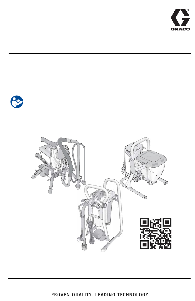
Operation, Parts
85a
graco.com/GX21op
GX Electric Airless
3A3212C
Sprayers
For professional use only.
Not approved for use in explosive atmospheres or hazardous locations.
For portable airless spraying of architectural paints and coatings.
Models: GX
3000 psi (207 bar, 20.7 MPa) Maximum Working Pressure
See page 4 for additional model information.
Important Safety Instructions
Read all warnings and instructions in this manual, related manuals, and on the unit
including the power cord. Be familiar with the controls and the proper usage of the
equipment. Save these instructions.
Related Manuals
Gun – 311861 (FTX) 312830 (SG3) Pump – 3A3172
EN
ti272
Use only genuine Graco replacement parts.
The use of non-Graco replacement parts may void warranty.
Page 2

Contents
Contents
Models . . . . . . . . . . . . . . . . . . . . . . . . . . . . . . . . . . . . . . . . . . . . . . . . . . . . . . . . . . . . . . . 4
Warnings . . . . . . . . . . . . . . . . . . . . . . . . . . . . . . . . . . . . . . . . . . . . . . . . . . . . . . . . . . . . . 5
Know Your Sprayer . . . . . . . . . . . . . . . . . . . . . . . . . . . . . . . . . . . . . . . . . . . . . . . . . . . . . 9
Stand Models . . . . . . . . . . . . . . . . . . . . . . . . . . . . . . . . . . . . . . . . . . . . . . . . . . . . . . . 9
DI Stand Models . . . . . . . . . . . . . . . . . . . . . . . . . . . . . . . . . . . . . . . . . . . . . . . . . . . 10
Hopper Models . . . . . . . . . . . . . . . . . . . . . . . . . . . . . . . . . . . . . . . . . . . . . . . . . . . . 11
Setup . . . . . . . . . . . . . . . . . . . . . . . . . . . . . . . . . . . . . . . . . . . . . . . . . . . . . . . . . . . . . . . 12
Start Up . . . . . . . . . . . . . . . . . . . . . . . . . . . . . . . . . . . . . . . . . . . . . . . . . . . . . . . . . . . . . 13
Pressure Relief Procedure . . . . . . . . . . . . . . . . . . . . . . . . . . . . . . . . . . . . . . . . . . . . 13
Flush Storage Fluid . . . . . . . . . . . . . . . . . . . . . . . . . . . . . . . . . . . . . . . . . . . . . . . . . 14
Fill Pump . . . . . . . . . . . . . . . . . . . . . . . . . . . . . . . . . . . . . . . . . . . . . . . . . . . . . . . . . 16
Fill Gun . . . . . . . . . . . . . . . . . . . . . . . . . . . . . . . . . . . . . . . . . . . . . . . . . . . . . . . . . . 16
How to Spray . . . . . . . . . . . . . . . . . . . . . . . . . . . . . . . . . . . . . . . . . . . . . . . . . . . . . . . . . 18
Spray Tip Installation . . . . . . . . . . . . . . . . . . . . . . . . . . . . . . . . . . . . . . . . . . . . . . . . 18
Adjust Pressure Control . . . . . . . . . . . . . . . . . . . . . . . . . . . . . . . . . . . . . . . . . . . . . . 19
Tip and Pressure Selection . . . . . . . . . . . . . . . . . . . . . . . . . . . . . . . . . . . . . . . . . . . 19
Spray Techniques . . . . . . . . . . . . . . . . . . . . . . . . . . . . . . . . . . . . . . . . . . . . . . . . . . 20
Triggering Gun . . . . . . . . . . . . . . . . . . . . . . . . . . . . . . . . . . . . . . . . . . . . . . . . . . . . . 20
Aiming Gun . . . . . . . . . . . . . . . . . . . . . . . . . . . . . . . . . . . . . . . . . . . . . . . . . . . . . . . 20
Spray Pattern Quality . . . . . . . . . . . . . . . . . . . . . . . . . . . . . . . . . . . . . . . . . . . . . . . . 20
Clear Tip Clog . . . . . . . . . . . . . . . . . . . . . . . . . . . . . . . . . . . . . . . . . . . . . . . . . . . . . 21
Cleanup . . . . . . . . . . . . . . . . . . . . . . . . . . . . . . . . . . . . . . . . . . . . . . . . . . . . . . . . . . . . . 22
Cleaning from a Pail . . . . . . . . . . . . . . . . . . . . . . . . . . . . . . . . . . . . . . . . . . . . . . . . 22
Power Flush . . . . . . . . . . . . . . . . . . . . . . . . . . . . . . . . . . . . . . . . . . . . . . . . . . . . . . . 24
Hopper Flushing . . . . . . . . . . . . . . . . . . . . . . . . . . . . . . . . . . . . . . . . . . . . . . . . . . . 26
Cleaning InstaClean
Clean the Gun . . . . . . . . . . . . . . . . . . . . . . . . . . . . . . . . . . . . . . . . . . . . . . . . . . . . . 28
Storage . . . . . . . . . . . . . . . . . . . . . . . . . . . . . . . . . . . . . . . . . . . . . . . . . . . . . . . . . . . . . . 29
Reference . . . . . . . . . . . . . . . . . . . . . . . . . . . . . . . . . . . . . . . . . . . . . . . . . . . . . . . . . . . . 30
Spray Tip Selection . . . . . . . . . . . . . . . . . . . . . . . . . . . . . . . . . . . . . . . . . . . . . . . . . 30
Cleaning Fluid Compatibility . . . . . . . . . . . . . . . . . . . . . . . . . . . . . . . . . . . . . . . . . . 30
Static Grounding Instructions . . . . . . . . . . . . . . . . . . . . . . . . . . . . . . . . . . . . . . . . . . 31
Quick Reference . . . . . . . . . . . . . . . . . . . . . . . . . . . . . . . . . . . . . . . . . . . . . . . . . . . 32
Maintenance . . . . . . . . . . . . . . . . . . . . . . . . . . . . . . . . . . . . . . . . . . . . . . . . . . . . . . . . . 33
Airless Hoses . . . . . . . . . . . . . . . . . . . . . . . . . . . . . . . . . . . . . . . . . . . . . . . . . . . . . . 33
Spray Tips . . . . . . . . . . . . . . . . . . . . . . . . . . . . . . . . . . . . . . . . . . . . . . . . . . . . . . . . 33
Pump Repair . . . . . . . . . . . . . . . . . . . . . . . . . . . . . . . . . . . . . . . . . . . . . . . . . . . . . . 33
Troubleshooting . . . . . . . . . . . . . . . . . . . . . . . . . . . . . . . . . . . . . . . . . . . . . . . . . . . . . . 36
17H211, 17H214 Stand Sprayers . . . . . . . . . . . . . . . . . . . . . . . . . . . . . . . . . . . . . . . . . 40
17H211, 17H214 Stand Sprayers Parts List . . . . . . . . . . . . . . . . . . . . . . . . . . . . . . 41
24Y680, 17G183, 17H218, 17H219, 17H221 DI Stand Sprayers . . . . . . . . . . . . . . . . . 42
24Y680, 17G183, 17H218, 17H219, 17H221 DI Stand Sprayers Parts List . . . . . . 43
™
Fluid Filter . . . . . . . . . . . . . . . . . . . . . . . . . . . . . . . . . . . . . . 28
2 3A3212C
Page 3

Contents
17F924, 17G184, 17H222, 17H223 Hopper Sprayers . . . . . . . . . . . . . . . . . . . . . . . . .44
17F924, 17G184, 17H222, 17H223 Hopper Sprayers Parts List . . . . . . . . . . . . . . . 45
Pump Assembly . . . . . . . . . . . . . . . . . . . . . . . . . . . . . . . . . . . . . . . . . . . . . . . . . . . . . . 46
Pump Parts List . . . . . . . . . . . . . . . . . . . . . . . . . . . . . . . . . . . . . . . . . . . . . . . . . . . .47
Wiring Diagrams . . . . . . . . . . . . . . . . . . . . . . . . . . . . . . . . . . . . . . . . . . . . . . . . . . . . . . 48
110/120V . . . . . . . . . . . . . . . . . . . . . . . . . . . . . . . . . . . . . . . . . . . . . . . . . . . . . . . . .48
230V . . . . . . . . . . . . . . . . . . . . . . . . . . . . . . . . . . . . . . . . . . . . . . . . . . . . . . . . . . . . . 49
Technical Specifications . . . . . . . . . . . . . . . . . . . . . . . . . . . . . . . . . . . . . . . . . . . . . . .50
GX 19, GX 21, FinishPro GX 19 . . . . . . . . . . . . . . . . . . . . . . . . . . . . . . . . . . . . . . .50
GX FF . . . . . . . . . . . . . . . . . . . . . . . . . . . . . . . . . . . . . . . . . . . . . . . . . . . . . . . . . . . 52
Graco Standard Warranty . . . . . . . . . . . . . . . . . . . . . . . . . . . . . . . . . . . . . . . . . . . . . . . 53
Graco Information . . . . . . . . . . . . . . . . . . . . . . . . . . . . . . . . . . . . . . . . . . . . . . . . . . . . . 54
Thank You for Your Purchase!
Before using your sprayer read this Owners Manual for complete instructions on proper use and
safety warnings.
Congratulations! You have pur chased a high-quality paint sprayer made by Graco I nc. This
sprayer is designed to provide superior spray performance with architectural paints and
coatings.
Please read the information on th e ma te rial container label to determine if i t can be use d wi th
your sprayer. Ask for a Safety Data Sheet (SDS) from your supplier. The container label and
SDS will explain the contents of the material and the specific precautions relate d to it.
3A3212C 3
Page 4
Models
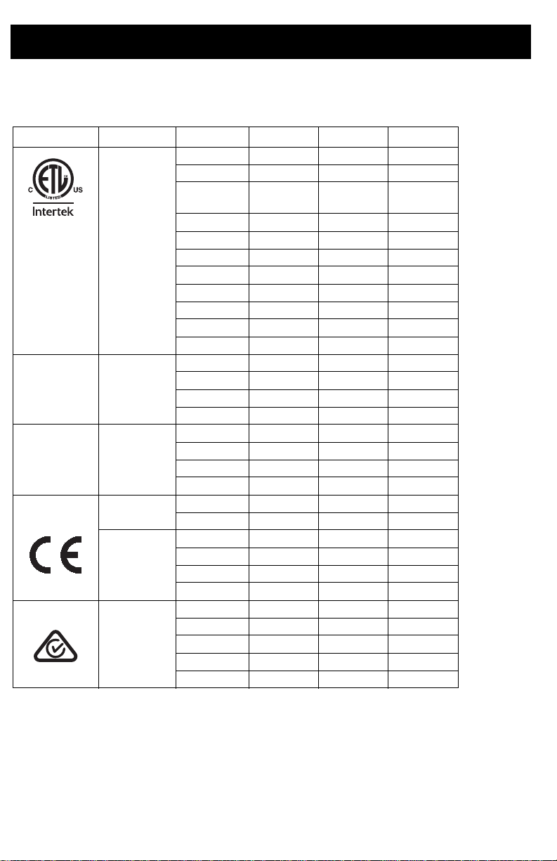
Models
VAC Model Stand DI Stand Hopper
GX 19 17H211
GX 21 24Y680
FinishPro
GX 19
17F924
110474
Certified to
CAN/CSA
C22.2 No. 68
Conforms to
UL 1450
SA & Brazil
CA & Brazil 110
120
USA
230
Schuko
230 Europe
Multi
230
Schuko
230
Schuko
Asia/ANZ
GX 21 17H221
®
GX 21 24Y680
GX 21 17H218
GX FF 17H222
GX 21 17G183
GX FF 17G184
GX 21 17H219
GX 19 17H214
GX 19 17H223
4 3A3212C
Page 5
Warnings
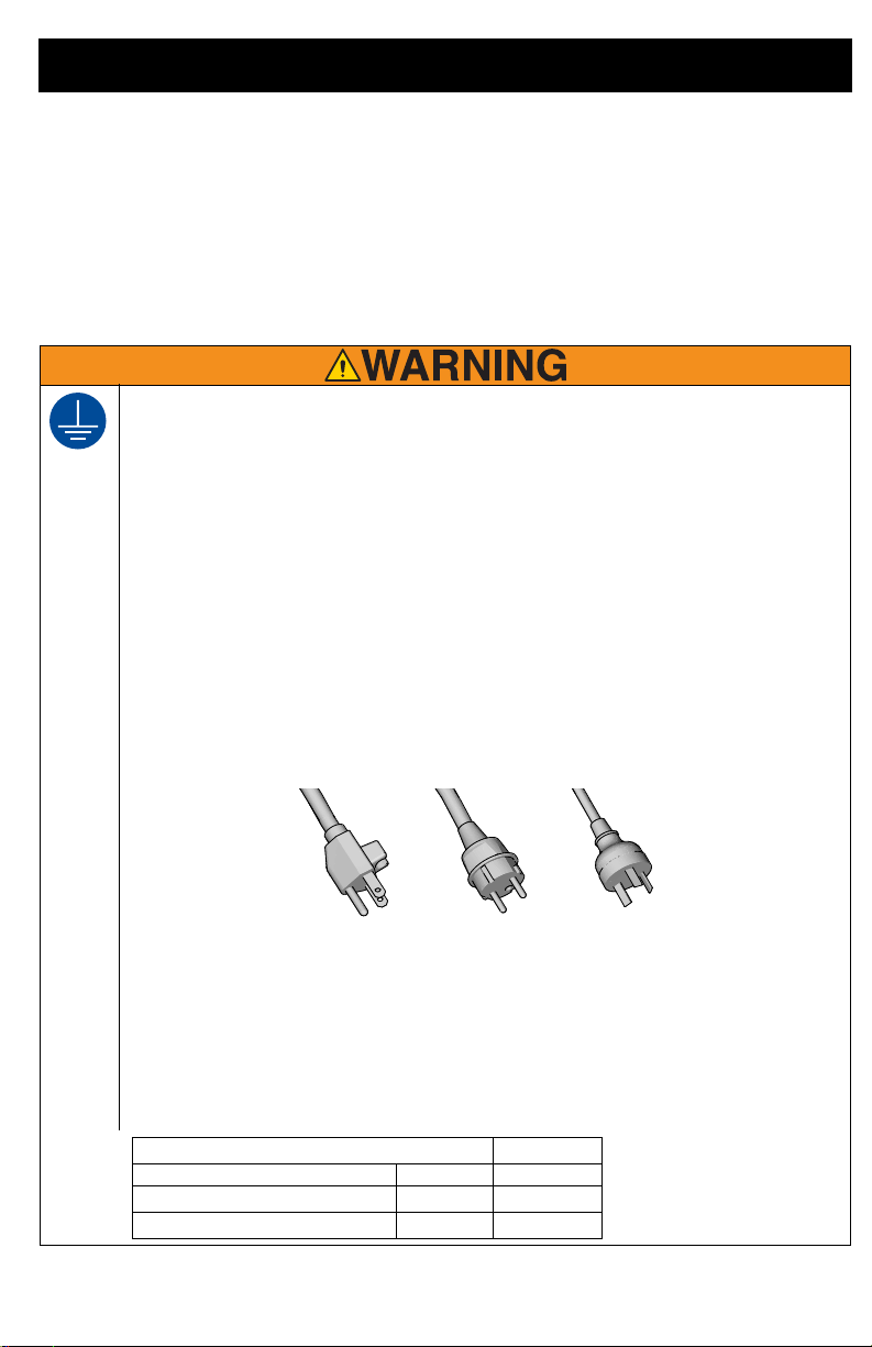
120V US 230V
230V ANZ
Conductor Size Length
AWG (American Wire Gauge) Metric Maximum
16
1.5 mm
2
25 ft. (8 m)
12
2.5 mm
2
50 ft. (15 m)
Warnings
The following warnings are for the setup, use, grounding, maintenance, and repair of this
equipment. The exclamation point symbol alerts you to a general warning and the hazard
symbols refer to procedure-specific risks. When these symbols appear in the body of this
manual or on warning labels, refer back to these Warnings. Product-specific hazard symbols
and warnings not covered in this section may appear throughout the body of this manual
where applicable.
GROUNDING
This product must be grounded. In the event of an electrical short circuit, grounding reduces
the risk of electric shock by providing an escape wire for the electric current. This product is
equipped with a cord having a grounding wire with an appropriate grounding plug. The plug
must be plugged into an outlet that is properly installed and grounded in accordance with all
local codes and ordinances.
• Improper installation of the grounding plug is able to result in a risk of electric shock.
• When repair or replacement of the cord or plug is required, do not connect the grounding
wire to either flat blade terminal.
• The wire with insulation having an outer surface that is green with or without yellow stripes
is the grounding wire.
• Check with a qualified electrician or serviceman when the grounding instructions are not
completely understood, or when in doubt as to whether the product is properly grounded.
• Do not modify the plug provided; if it does not fit the outlet, have the proper outlet installed
by a qualified electrician.
• This product is for use on a nominal 120V or 230V circuit and has a grounding plug similar
to the plugs illustrated below.
ti24583b
• Only connect the product to an outlet having the same configuration as the plug.
• Do not use an adapter with this product.
Extension Cords:
•
Use only a 3-wire extension cord that has a grounding plug and a grounding receptacle that
accepts the plug on the product.
• Make sure your extension cord is not damaged. If an extension cord is necessary use 12
AWG (2.5mm
2
) minimum to carry the current that the product draws.
• An undersized cord results in a drop in line voltage and loss of power and overheating.
3A3212C 5
Page 6
Warnings
FIRE AND EXPLOSION HAZARD
Flammable fumes, such as solvent and paint fumes, in work area can ignite or explode. To help
prevent fire and explosion:
• Do not spray combustible materials near an open flame or sources of ignition such as
cigarettes, motors, and electrical equipment.
• Paint or solvent flowing through the equipment is able to result in static electricity. Static
electricity creates a risk of fire or explosion in the presence of paint or solvent fumes. All
parts of the spray system, including the pump, hose assembly, spray gun, and objects in
and around the spray area shall be properly grounded to protect against static discharge
and sparks. Use Graco conductive or grounded high-pressure airless paint sprayer hoses.
• Verify that all containers and collection systems are grounded to prevent static discharge.
Do not use pail liners unless they are anti-static or conductive.
• Connect to a grounded outlet and use grounded extensions cords. Do not use a 3-to-2
adapter.
• Do not use a paint or a solvent containing halogenated hydrocarbons.
• Do not spray combustible liquids in a confined area.
• Keep spray area well-ventilated. Keep a good supply of fresh air moving through the area.
• Sprayer generates sparks. Keep pump assembly in a well ventilated area a least 20 feet
(6.1 m) from the spray area when spraying, flushing, cleaning, or servicing. Do not spray
pump assembly.
• Do not smoke in the spray area or spray where sparks or flame is present.
• Do not operate light switches, engines, or similar spark producing products in the spray
area.
• Keep area clean and free of paint or solvent containers, rags, and other flammable
materials.
• Know the contents of the paints and solvents being sprayed. Read all Safety Data Sheet
(SDS) and container labels provided with the paints and solvents. Follow the paint and
solvents manufacturer’s safety instructions.
• Fire extinguisher equipment shall be present and working.
6 3A3212C
Page 7
Warnings
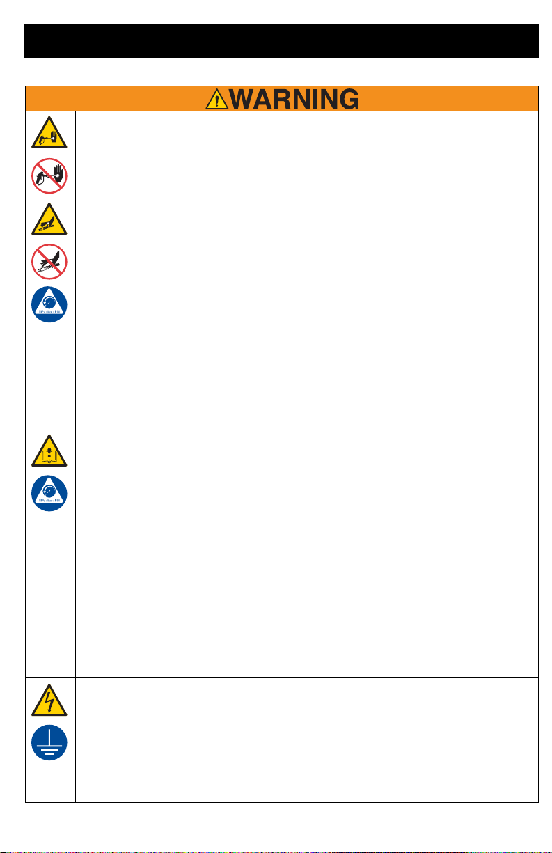
SKIN INJECTION HAZARD
High-pressure spray is able to inject toxins into the body and cause serious bodily injury. In the
event that injection occurs, get immediate surgical treatment.
• Do not aim the gun at, or spray any person or animal.
• Keep hands and other body parts away from the discharge. For example, do not try to stop
leaks with any part of the body.
• Always use the nozzle tip guard. Do not spray without nozzle tip guard in place.
• Use Graco nozzle tips.
• Use caution when cleaning and changing nozzle tips. In the case where the nozzle tip clogs
while spraying, follow the Pressure Relief Procedure for turning off the unit and relieving
the pressure before removing the nozzle tip to clean.
• Equipment maintains pressure after power is shut off. Do not leave the equipment
energized or under pressure while unattended. Follow the Pressure Relief Procedure
when the equipment is unattended or not in use, and before servicing, cleaning, or
removing parts.
• Check hoses and parts for signs of damage. Replace any damaged hoses or parts.
• This system is capable of producing 3000 psi. Use Graco replacement parts or accessories
that are rated a minimum of 3000 psi.
• Always engage the trigger lock when not spraying. Verify the trigger lock is functioning
properly.
• Verify that all connections are secure before operating the unit.
• Know how to stop the unit and bleed pressure quickly. Be thoroughly familiar with the
controls.
EQUIPMENT MISUSE HAZARD
Misuse can cause death or serious injury.
• Always wear appropriate gloves, eye protection, and a respirator or mask when painting.
• Do not operate or spray near children. Keep children away from equipment at all times.
• Do not overreach or stand on an unstable support. Keep effective footing and balance at
all times.
• Stay alert and watch what you are doing.
• Do not operate the unit when fatigued or under the influence of drugs or alcohol.
• Do not kink or over-bend the hose.
• Do not expose the hose to temperatures or to pressures in excess of those specified by
Graco.
• Do not use the hose as a strength member to pull or lift the equipment.
• Do not spray with a hose shorter than 25 feet.
• Do not alter or modify equipment. Alterations or modifications may void agency approvals
and create safety hazards.
• Make sure all equipment is rated and approved for the environment in which you are using
it.
ELECTRIC SHOCK HAZARD
This equipment must be grounded. Improper grounding, setup, or usage of the system can
cause electric shock.
• Turn off and disconnect power cord before servicing equipment.
• Connect only to grounded electrical outlets.
• Use only 3-wire extension cords.
• Ensure ground prongs are intact on power and extension cords.
• Do not expose to rain. Store indoors.
3A3212C 7
Page 8
Warnings
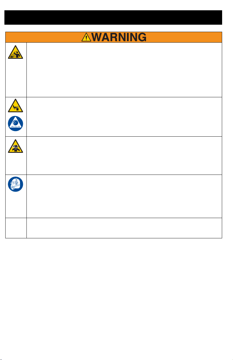
PRESSURIZED ALUMINUM PARTS HAZARD
Use of fluids that are incompatible with aluminum in pressurized equipment can cause serious
chemical reaction and equipment rupture. Failure to follow this warning can result in death,
serious injury, or property damage.
• Do not use 1,1,1-trichloroethane, methylene chloride, other halogenated hydrocarbon
solvents or fluids containing such solvents.
• Do not use chlorine bleach.
• Many other fluids may contain chemicals that can react with aluminum. Contact your
material supplier for compatibility.
MOVING PARTS HAZARD
Moving parts can pinch, cut, or amputate fingers and other body parts.
• Keep clear of moving parts.
• Do not operate equipment with protective guards or covers removed.
• Pressurized equipment can start without warning. Before checking, moving, or servicing
equipment, follow the Pressure Relief Procedure and disconnect all power sources.
TOXIC FLUID OR FUMES HAZARD
Toxic fluids or fumes can cause serious injury or death if splashed in the eyes or on skin,
inhaled, or swallowed.
• Read MSDSs to know the specific hazards of the fluids you are using.
• Store hazardous fluid in approved containers, and dispose of it according to applicable
guidelines.
PERSONAL PROTECTIVE EQUIPMENT
Wear appropriate protective equipment when in the work area to help prevent serious injury,
including eye injury, hearing loss, inhalation of toxic fumes, and burns. This protective
equipment includes but is not limited to:
• Protective eyewear, and hearing protection.
• Respirators, protective clothing, and gloves as recommended by the fluid and solvent
manufacturer.
CALIFORNIA PROPOSITION 65
This product contains a chemical known to the State of California to cause cancer, birth defects
or other reproductive harm. Wash hands after handling.
8 3A3212C
Page 9
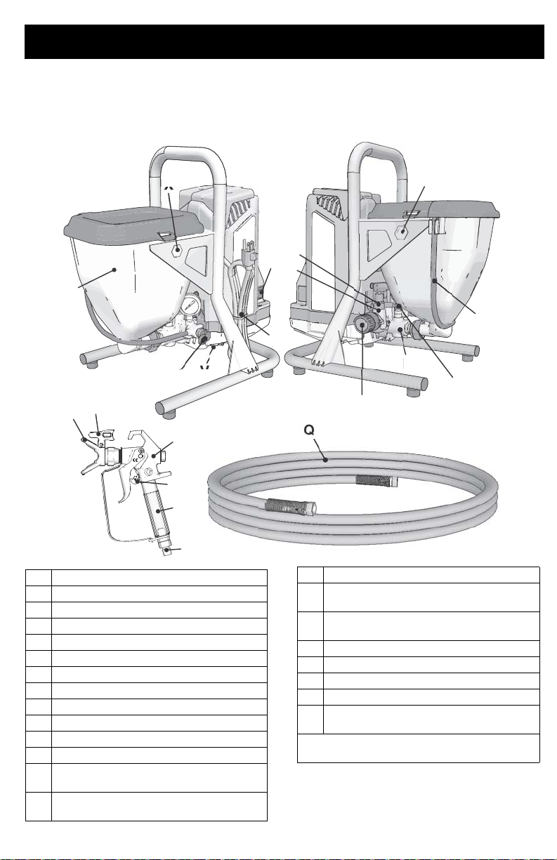
Know Your Sprayer
C
V
X/Z
N
R
P
D
E
F
B
Q
G
H
J
K
M
L
A
T
U
W
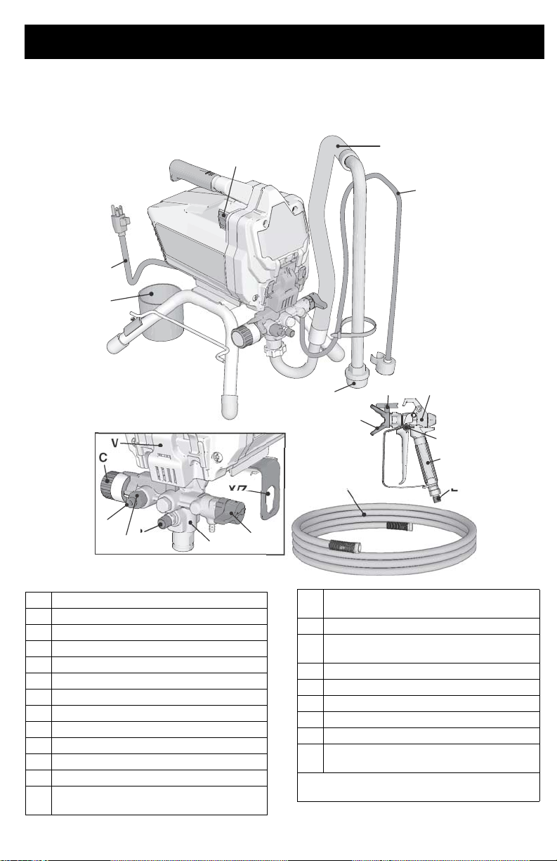
Stand Models
Know Your Sprayer
A Prime / Spray Valve
B PushPrime™ Button
C Pressure Control Knob
D ON/OFF Switch
E Suction Tube
F Drain Tube (with diffuser)
G Airless Spray Gun
H Reversible Spray Tip
J Tip Guard
K Gun Trigger Lock
L Gun Fluid Inlet Fitting
M Gun Fluid Filter (inside handle)
N ProXChange™ Pump (behind Easy
Access Door)
3A3212C 9
ti27260a
P Pump Fluid Outlet Fitting (airless
hose connection)
Q Airless Hose
R InstaClean™ Fluid Filter (inside fluid
outlet)
T Inlet Strainer
U Power Cord
V Easy Access Door
W Suction / Drain Tube Cup
X/Z Pump & Inlet Valve Removal Tool
See Quick Reference, page 32 for more
information.
Model/Serial Tag (Not shown, located
on bottom of unit.)
Page 10
Know Your Sprayer
X
Z
D
B
F
T
E
N
R
V
A
C
P
W
J
Q
U
H
G
K
L
M
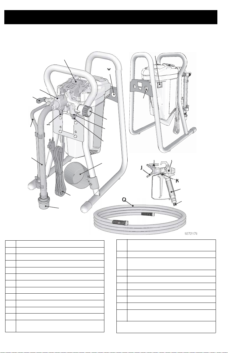
DI Stand Models
A Prime / Spray Valve
B PushPrime Button
C Pressure Control Knob
D ON/OFF Switch
E Suction Tube
F Drain Tube (with diffuser)
G Airless Spray Gun
H Reversible Spray Tip
J Tip Guard
K Gun Trigger Lock
L Gun Fluid Inlet Fitting
M Gun Fluid Filter (inside handle)
N ProXChange™ Pump (behind Easy
Access Door)
P Pump Fluid Outlet Fitting (airless
hose connection)
Q Airless Hose
R InstaClean™ Fluid Filter (inside fluid
outlet)
T Inlet Strainer
U Power Cord
V Easy Access Door with Cover
W Suction / Drain Tube Cup
X Pump Removal Tool
Z Inlet Valve Removal Tool
See Quick Reference, page 32 for more
information.
Model/Serial Tag (Not shown, located
on bottom of unit.)
10 3A3212C
Page 11
Hopper Models
X
Z
A
V
B
N
F
C
D
U
P
R
E
J
H
G
K
M
a
Q
Know Your Sprayer
ti27262
A Prime / Spray Valve
B PushPrime Button
C Pressure Control Knob
D ON/OFF Switch
E Hopper
F Drain Tube (with diffuser)
G Airless Spray Gun FTX
H Reversible Spray Tip, Fine Finish
J Tip Guard
K Gun Trigger Lock
L Gun Fluid Inlet Fitting
M Gun Fluid Filter (inside handle)
N ProXChange™ Pump (behind Easy
Access Door)
P Pump Fluid Outlet Fitting (airless
hose connection)
3A3212C 11
L
Q Airless Hose
R InstaClean™ Fluid Filter (inside fluid
T Inlet Strainer, inside hopper not
U Power Cord
V Easy Access Door
X Pump Removal Tool
Z Inlet Valve Removal Tool
See Quick Reference, page 32 for more
information.
outlet)
shown
Model/Serial Tag (Not shown, located
on bottom of unit.)
Page 12
Setup
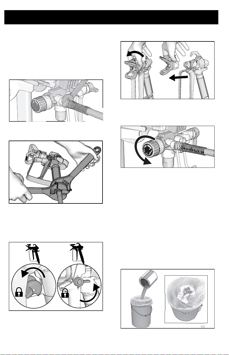
Setup
When unpacking sprayer for the first time or
after long term storage perform setup
procedure.
1. Connect Graco airless hose to fluid
outlet. Use wrench to tighten securely.
ti27122a
2. Connect other end of hose to gun.
ti25199a
3. Use wrenches to tighten securely. If
hose is already connected, make sure
connections are tight.
4. Engage trigger lock.
5. Remove tip guard. Do not lose the seal.
ti25197a
6. Turn Pressure Control Knob all the way
left (counter-clockwise) to minimum
pressure.
ti27123a
7. When unpacking sprayer for the first
time remove packaging materials from
inlet strainer. After long term storage
check inlet strainer for clogs and debris.
Strain the Paint
Previously opened paint may contain dried
paint or other debris. To avoid priming problems and spray tip clogs it is recommended
to strain the paint before using. Paint strainers are available where paint is sold. Stretch
a paint strainer over a clean pail and pour
the paint through the strainer to capture any
dried paint and debris before spraying.
ti24931a
ti26894a
12 3A3212C
Page 13
Start Up
ti27118a
Start Up
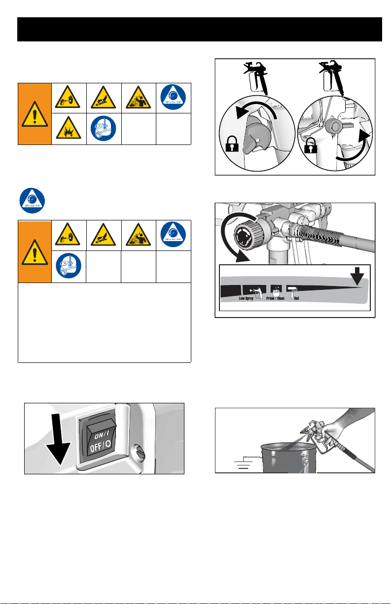
Pressure Relief Procedure
Follow the Pressure Relief
Procedure whenever you see this
symbol.
This equipment stays pressurized until
pressure is manually relieved. To help
prevent serious injury from pressurized
fluid, such as skin injection or splashed
fluid, follow the Pressure Relief
Procedure whenever sprayer is stopped
and before sprayer is cleaned or checked,
and before equipment is serviced.
1. Turn ON/OFF switch to the OFF
position.
ti24931a
3. Turn pressure control to lowest setting.
ti27493a
4. Put drain tube into a pail and place
Prime/Spray valve in PRIME position
(drain) to relieve pressure.
5. Hold the gun firmly to a pail, point gun
into pail. Disengage the trigger lock and
trigger the gun to relieve pressure.
ti25497b
2. Engage the trigger lock. Always engage
the trigger lock when sprayer is stopped
to prevent the gun from being triggered
accidentally.
3A3212C 13
6. Engage the trigger lock.
7. If you suspect the spray tip or hose is
clogged or that pressure has not been
fully relieved:
a. VERY SLOWLY loosen the spray
tip guard retaining nut or the hose
end coupling to relieve pressure
gradually.
Page 14
Start Up
ti27264a
ti27118a
ti27266a
b. Loosen the nut or coupli ng
completely.
c. Clear airless hose or spray tip
obstruction.
Prime/Spray Valve
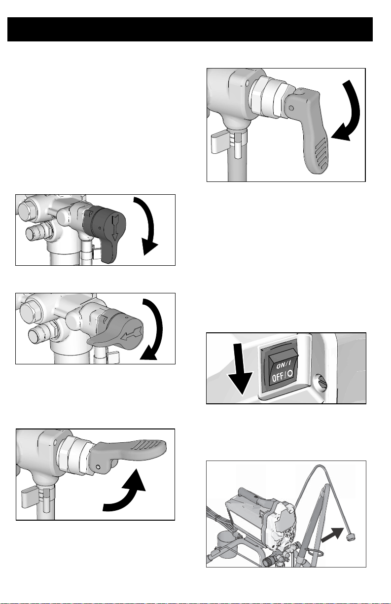
There are two types of Prime/Spray valves
used on this group of Graco sprayers.
The first type of Prime/Spray valve uses a
knob that can be turned between the PRIME
and SPRAY position.
PRIME GX 19
ti27120a
SPRAY GX 19
SPRAY FinishPro GX 19, GX 21
Flush Storage Fluid
This sprayer arrives from the factory with a
small amount of test material in the system.
is important that you flush this material
from the sprayer before using it for the first
time.
See
page 30 and
Instructions
information.
1. Perform Pressure Relief Procedure,
2. Make certain ON/OFF switch is OFF.
Cleaning Fluid Compatibility
Static Grounding
, page 31 for additional
page 13.
It
,
ti27121a
The other type of Prime/Spray valve uses a
lever that can be flipped between the PRIME
and SPRAY position.
PRIME FinishPro GX 19, GX 21
Stand Models
a. Separate drain tube (smaller) from
suction tube (larger).
ti27263a
14 3A3212C
Page 15
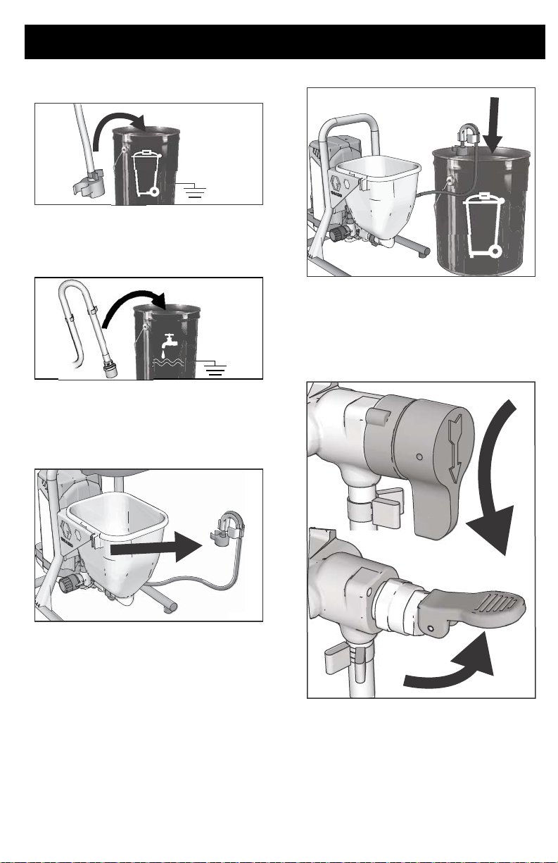
b. Place drain tube in waste pail.
ti27133a
2
ti27232a
ti27125a
c. Submerge suction tube in a pail
partially filled with water or flushing
fluid.
Hopper Models
a. Lift drain tube with retainer off the
hopper.
Start Up
ti27268a
c. Pour approximately two quarts (two
liters) of water or flushing fluid into
the hopper.
3. Place Prime/Spray valve in PRIME
position.
65ati27
b. While holding the drain tube retainer
with drain tube parallel to the top of
a waste pail twist retainer over the
lip of the pail. Drain tube should now
be inside the waste pail.
4. Plug power supply cord into a properly
grounded electrical outlet.
3A3212C 15
Page 16
Start Up
36a
ti27134a
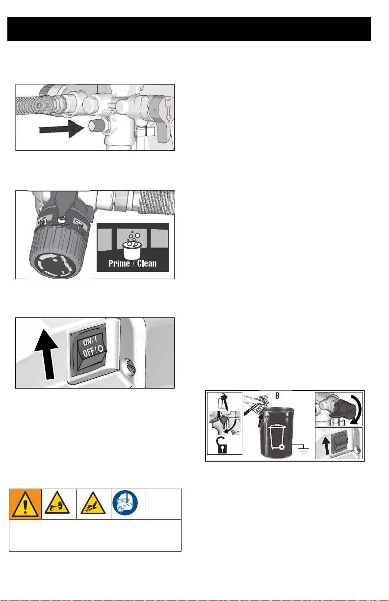
5. Press PushPrime button twice to
loosen inlet ball.
ti271
6. Align setting indicator with Prime/Clean
setting on Pressure Control Knob.
ti27135a
7. Turn ON/OFF switch to ON position.
10. Inspect for leaks. If leaks occur, perform Pressure Relief Procedure, page
13, then tighten all fittings and repeat
Start Up. If there are no leaks continue
with the next step.
Fill Pump
1. Move suction tube to paint pail and
submerge suction tube in paint. On
hopper models and add paint to the
hopper.
2. Turn ON/OFF switch to ON position.
3. Wait to see paint coming out of the
drain tube.
4. Turn ON/OFF switch to OFF position.
NOTE: Some fluids may prime faster if
the ON/OFF switch is momentarily
turned off so the pump can slow and
stop. Turn ON/OFF switch on and off
several times if necessary.
Fill Gun
1. Hold gun against waste pail. Point gun
into waste pail.
a. Disengage trigger lock.
b. Pull and hold gun trigger.
c. Turn Prime/Spray valve to SPRAY
position.
d. Turn ON/OFF switch to ON posi-
tion.
8. When sprayer starts pumping, flushing
A
B
C
solvent and air bubbles will be purged
from system. Allow fluid to flow out of
drain tube into waste pail for 30 to 60
D
seconds. On hopper models, allow fluid
to flow out of drain tube until hopper is
nearly empty.
9. Turn ON/OFF switch to OFF position.
ti27867a
2. Trigger gun into waste pail until only
paint comes out of the gun.
High-pressure spray is able to inject toxins
into the body and cause serious bodily
injury. Do not stop leaks with hand or rag.
16 3A3212C
Page 17
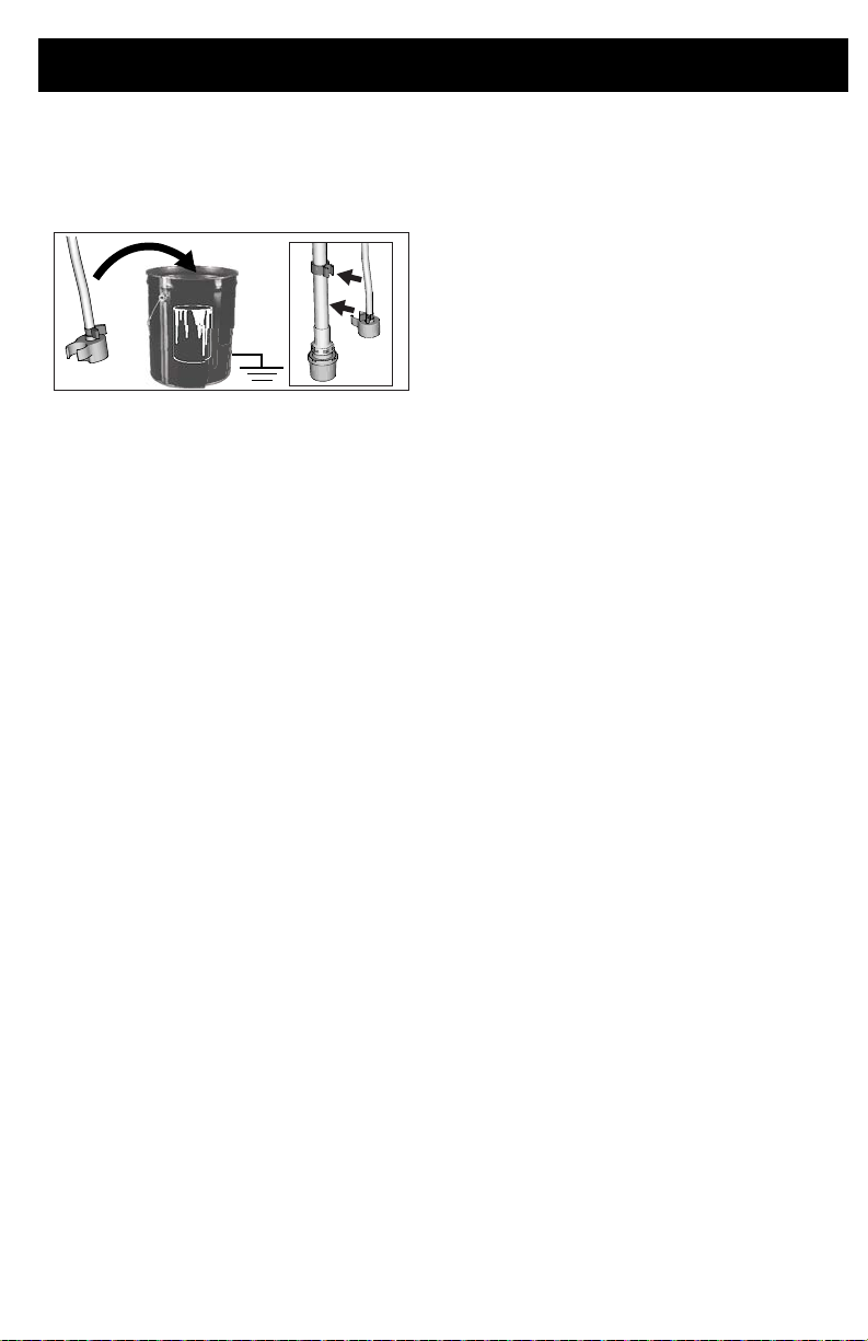
3. Release trigger. Engage trigger lock.
4.
Transfer drain tube to paint pail and clip
to suction tube.
drain tube to hopper.
ti27139a
NOTE: When motor stops sprayer is ready
to paint. If motor continues to run sprayer is
not properly primed, repeat Fill Pump and
Fill Gun.
On hopper models, clip
Start Up
3A3212C 17
Page 18
How to Spray
TIP
GUARD
RETAINING
NUT
RUBBER
GASKET/
METAL SEAL
SPRAY
TIP
0a
3a
5a
ti27480a
How to Spray
Spray Tip Installation
b. Spray tip must be pushed all the
way into the tip guard. Turn spray tip
to push down.
To prevent spray tip leaks make certain spray
tip and tip guard are installed properly.
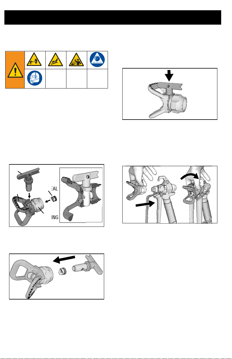
1. Perform Pressure Relief Procedure,
page 13.
2. Engage trigger lock.
3. Verify spray tip and tip guard parts are
assembled in the order shown.
ti2714
a. Use spray tip to align gasket an d
seal in the tip guard.
ti2714
c. Turn the arrow shaped handle on
the spray tip forward to the spray
position.
4. Screw spray tip assembly onto the gun
and tighten.
18 3A3212C
ti2714
Page 19
How to Spray
3000 psi
(207 bar, 20.7 MPa)
ti5597b
1500 psi
(103 bar, 10.3 MPa)
500 psi
(34.5 bar, 3.5 MPa)
Adjust Pressure Control
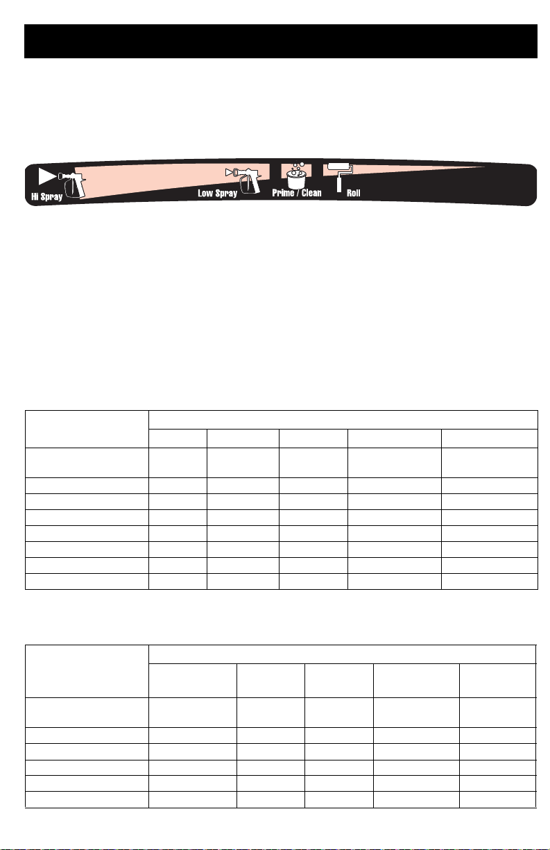
The pressure control knob allows for infinite pressure adjustment. To reduce overspray, always
start at the lowest pressure setting and increase pressure to the minimum setting that results
in an acceptable spray pattern.
To select function, align symbol on pressure control knob with setting indicator on
sprayer.
Tip and Pressure Selection
See table for recommended spray pressure for your m aterial. Refer to paint (material)
can for manufacturer’s recommendations.
Maximum tip hole sizes supported by the sprayer:
– GXFF, GX19, FinishPro GX19: 0.019 in. (0.48 mm)
– GX21: 0.021 in. (0.53 mm)
Coatings
Stains Enamels Primers Interior Paints Exterior Paints
Spray Pressure
Setting
Tip Hole Size
0.011 in. (0.28 mm)
0.013 in. (0.33 mm)
0.015 in. (0.38 mm)
0.017 in. (0.43 mm)
0.019 in. (0.48 mm)
0.021 in. (0.53 mm)
Low
Spray
Low Spray High Spray High Spray High Spray
Fine Finish Tips
Fine Finish tips have an additional orifice that provides a finer atomization of the material .
Coatings
Sanding
Size
Spray Pressure
Setting
0.008 in. (0.20 mm)
0.010 in. (0.25 mm)
0.012 in. (0.31 mm)
0.014 in. (0.36 mm)
0.016 in. (0.41 mm)
3A3212C 19
Polyurethane Lacquer
Low Spray Low Spray Low Spray High Spray High Spray
Sealer Enamels Latex
Page 20
How to Spray
12 in.
(30 cm)
EVEN
FINISH
THICK
THIN
UNEVEN
FINISH
ti5585a
EVEN FINISH THIN THINTHICK
TIA
ti2038a
good
spray pattern
tails- gaps
at edges
pressure
too low
ti5592a
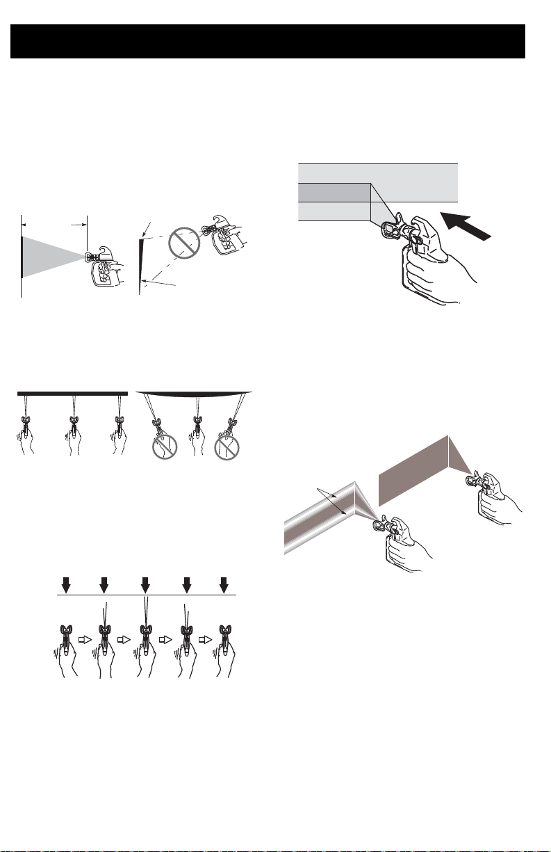
Spray Techniques
Use a piece of scrap cardboard to practice
these basic spraying techniques before you
begin spraying the surface.
• Hold gun 12 in. (30 cm) from surface
and aim straight at surface. Tilting gun
to direct spray angle causes an uneven
finish.
• Flex wrist to keep gun pointed straight.
Fanning gun to direct spray at angle
causes uneven finish.
Aiming Gun
Aim center of spray of gun at bottom edge of
previous stroke, overlapping each stroke by
half.
Spray Pattern Quality
A good spray pattern is evenly distributed as
it hits the surface.
• Spray should be atomized (evenly dis-
tributed, no gaps at edges).
Triggering Gun
Pull trigger after starting stroke. Release
trigger before end of stroke. Gun must be
moving when trigger is pulled and released.
If tails persist when spraying at the highest
spray pressure:
• Spray tip may be worn. See Spray Tip
Selection, page 30.
• A smaller spray tip may be needed.
• Material may need to be thinned. If
material needs to be thinned follow
manufacturer’s recommendations.
20 3A3212C
Page 21
Clear Tip Clog
ti24674a
ti24676a
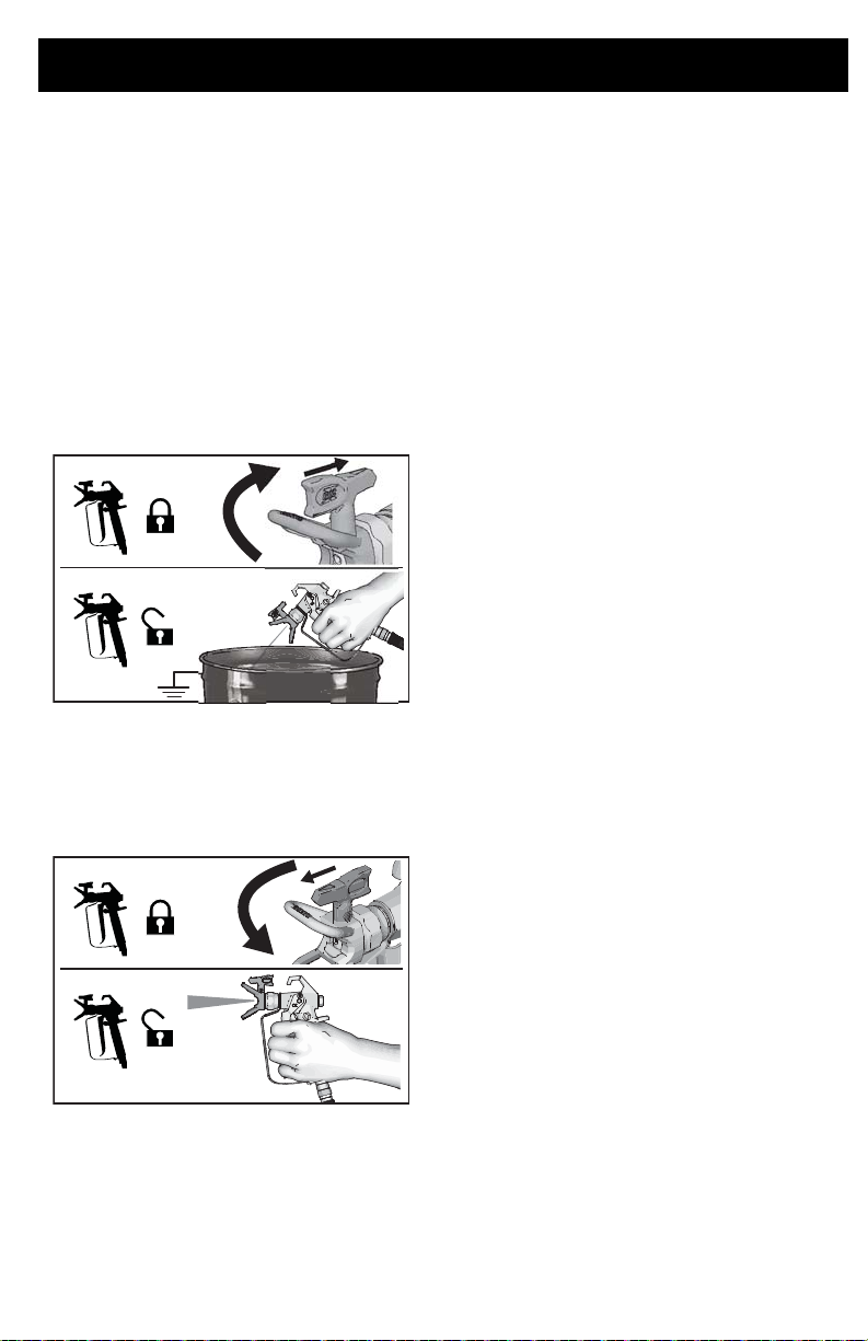
In the event that particles or debris clog the
spray tip, this sprayer is designed with a
reversible spray tip that quickly and easily
clears the particles without disassembling the
sprayer.
See Strain the Paint, page 12 for additional
information.
1. Release trigger. Engag e trigger lock.
Rotate spray tip to unclog position.
Disengage trigger lock. Trigger gun at
waste area to clear clog.
Unclog
How to Spray
2. Engage trigger lock. Rotate spray tip
back to spray position. Disengage trigger lock and continue spraying.
Spray
3A3212C 21
Page 22
Cleanup
ti27405a
ti27467a
Cleanup
Cleaning the sprayer after each use results in
a trouble free start up the next time the
sprayer is used.
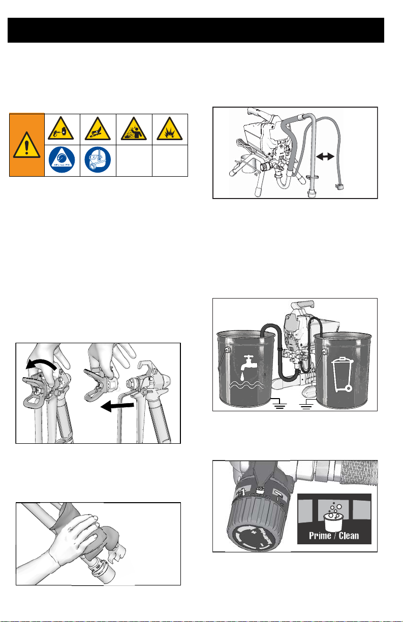
Cleaning from a Pail
(Stand Models Only)
Pail flushing only works with models that
have a suction tube.
• For long term storage refer to Storage,
page 29.
• See Cleaning Fluid Compatibility,
page 30 and Static Grounding
Instructions, page 31.
1. Perform Pressure Relief Procedure,
page 13.
2. Remove tip guard and spray tip.
4. Separate drain tube (smaller) from suction tube (larger).
5. Place empty waste and flushing fluid
pails side by side.
6. Place suction tube in flushing fluid. Use
water for water based paint and mineral
spirits or compatible oil-based flushing
solvent for oil-based paint. Place drain
tube in waste pail.
ti25197a
3. Remove suction tube and drain tube
from paint, wipe excess paint off outside.
ti27495a
22 3A3212C
7. Turn pressure control knob to the
Prime/Clean setting.
ti27135a
8. Place Prime/Spray valve in PRIME
position.
Page 23
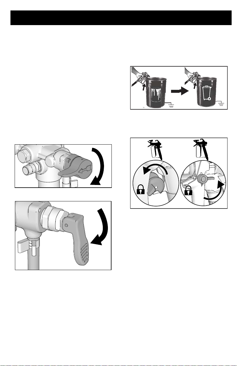
Cleanup
ti27264a
9. Turn ON/OFF switch to ON position.
10. Flush until approximately 1/3 of the
flushing fluid is emptied from the pail.
11. Turn ON/OFF switch to OFF position.
NOTE: Step 12 is for returning paint in airless paint hose to paint pail. One 50 ft (15
m) hose holds approximately 1 quart (1 liter)
of paint.
12. To recover paint in hose:
a. Hold gun firmly to the paint pail.
b. Point gun into paint pail.
c. Disengage trigger lock.
d. Pull and hold gun tri gger.
e. Place Prime/Spray valve in SPRAY
position.
ti27121a
13. While continuing to trigger gun, quickly
move gun to redirect spray into waste
pail. Continue triggering gun into waste
pail until flushing fluid dispensed from
gun is relatively clear.
ti27151a
14. Stop triggering gun. Engage the trigger
lock.
ti24931a
15. Place Prime/Spray valve in PRIME
position.
f. Turn ON/OFF switch to ON position.
g. Continue to hold gun trigger until
you see paint diluted with flushing
fluid starting to come out of gun.
3A3212C 23
Page 24
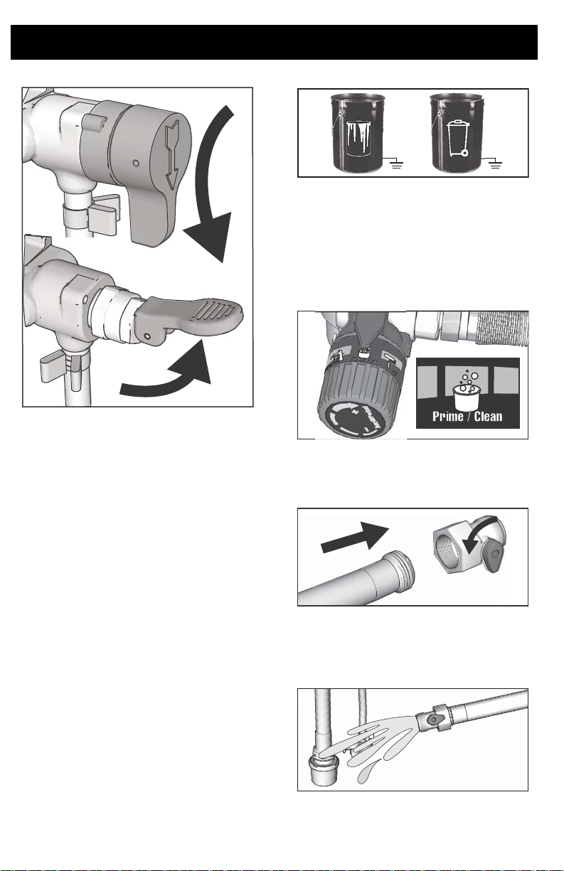
Cleanup
ti27232a
ti27153a
55ati27
ti27156a
16. Turn ON/OFF switch to OFF position.
17. Clean filter. See Cleaning Insta-
18. Fill unit with Pump Armor
™
Clean
Fluid Filter, page 28.
Storage, page 29.
™
fluid. See
4. Lift suction tube and drain tube from
paint pail. Let paint drain into the pail.
5. Place suction and drain tube in waste
pail.
6. Turn Pressure Control knob to the
Prime/Clean setting.
ti27135a
7. Screw power flush attachment valve to
garden hose. Close valve.
Power Flush
(GX 21, Water-based materials Only)
Power flushing is a faster method of flushing.
It can only be used after spraying
water-based coatings.
1. Perform Pressure Relief Procedure,
page 13.
2. Remove spray tip and tip guard assembly from gun and place in waste pail.
3. Place empty waste and paint pails side
by side.
24 3A3212C
8. Turn on water. Open valve. Rinse paint
off suction tube, drain tube and inlet
strainer then close valve.
1
Page 25
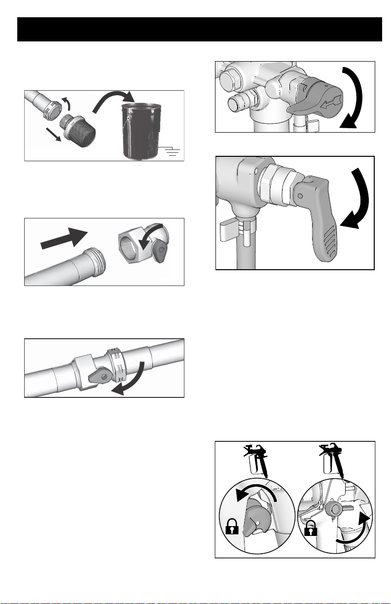
9. Unscrew inlet strainer from suction
ti27158a
55ati27
ti27160a
ti27264a
tube. Place inlet strainer rinse in waste
pail.
10. Connect garden hose to suction tube
with Power Flush attachment valve.
Leave drain tube in waste pail.
1
11. Turn ON/OFF switch to ON position.
12. Open Power flush attachment valve.
13. Circulate water through sprayer, into
waste pail, for 20 seconds.
14. Turn ON/OFF switch to OFF position.
NOTE: Step 15 is for returning paint in hose
to paint pail. One 50 ft (15 m) hose holds
approximately 1 quart (1 liter) of paint.
Cleanup
ti27121a
f. Turn ON/OFF switch to ON position.
g. Continue to hold gun trigger until
you see paint diluted with flushing
fluid starting to come out of gun.
16. While continuing to trigger gun, quickly
move gun to redirect spray into waste
pail. Continue triggering gun into waste
pail until flushing fluid dispensed from
gun is relatively clear.
17. Turn pressure control knob to the
Prime/Clean setting.
18. Stop triggering gun. Engage the trigger
lock.
15. To recover paint in hose:
a. Hold gun firmly to the paint pail.
b. Point gun into paint pail.
c. Disengage trigger lock.
d. Pull and hold gun tri gger.
e. Place Prime/Spray valve in SPRAY
position.
3A3212C 25
ti24931a
Page 26
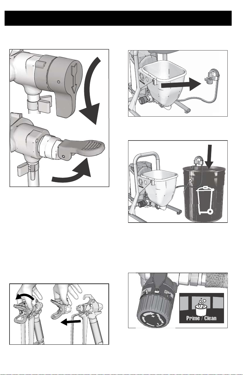
Cleanup
ti27232a
2
19. Place Prime/Spray valve in PRIME
position.
20. Turn ON/OFF switch to OFF position.
Hopper Flushing
(Hopper Models Only)
See Cleaning Fluid Compatibility, page 30.
1. Perform Pressure Relief Procedure,
page 13.
2. Pour any remaining material out of the
hopper.
3. Remove tip guard and Spray Tip. For
additional information, see Clean the
Gun, page 28.
4. Remove drain tube from paint hopper,
wipe excess paint off outside.
65ati27
5. Place drain tube in waste pail.
ti27268a
6. Pour flushing fluid into the hopper. Use
water for water-based paint and mineral
spirits for oil-based paint.
7. Turn pressure control knob to the
Prime/Clean setting.
ti27135a
ti25197a
8. Turn ON/OFF switch to ON position.
26 3A3212C
Page 27
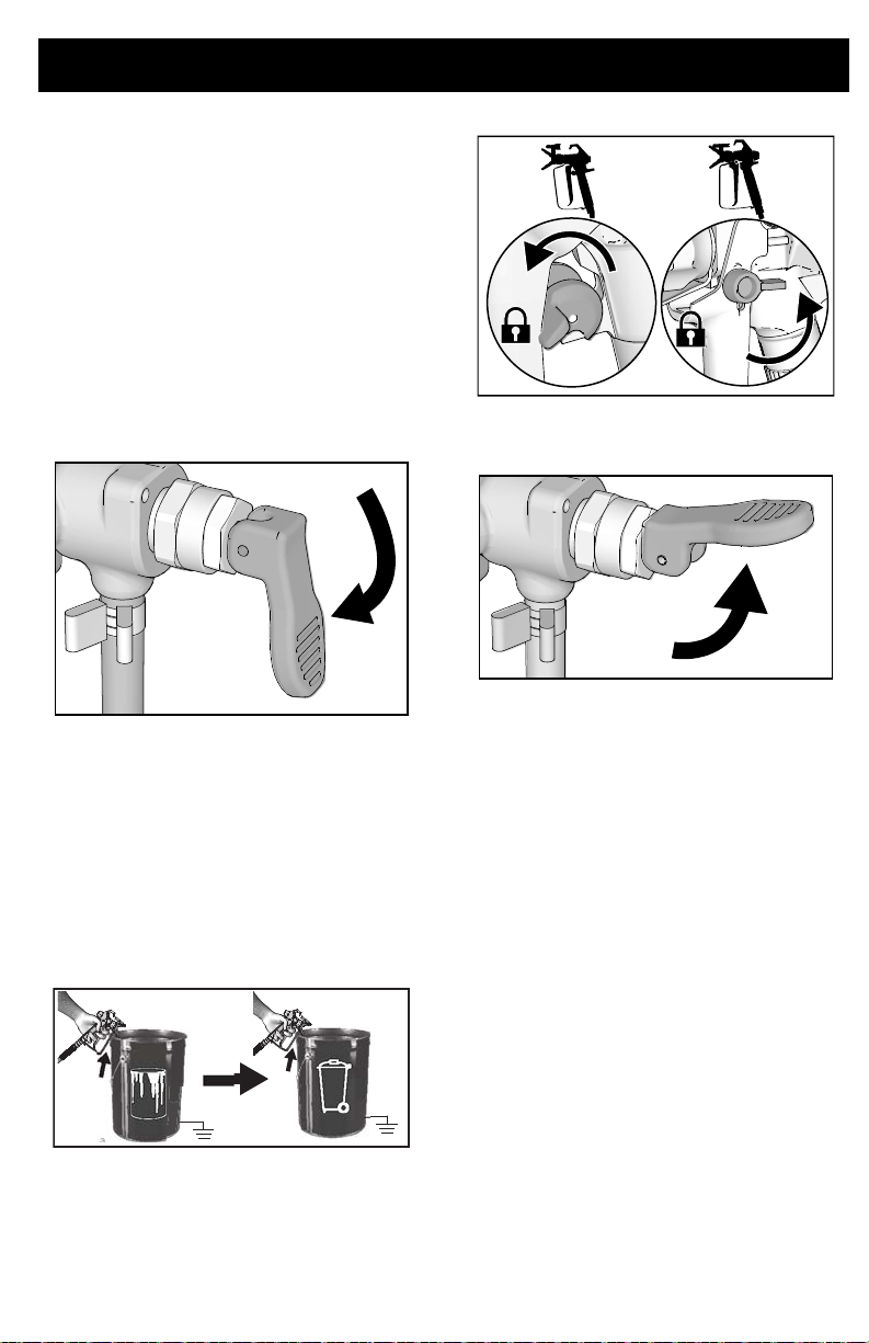
9. Flush until approximately 1/3 of the
ti27264a
flushing fluid is emptied from the hopper.
10. Turn ON/OFF switch to OFF position.
NOTE: Step 11 is for returning paint in hose
to paint pail. One 50 ft (15 m) hose holds
approximately 1 quart (1 liter) of paint.
11. To recover paint in hose:
a. Point gun into paint pail.
b. Disengage trigger lock.
c. Pull and hold gun trigger.
d. Place Prime/Spray valve in SPRAY
position.
e. Turn ON/OFF switch to ON position.
f. Continue to hold gun trigger until
you see paint diluted with flushing
fluid starting to come out of gun.
12. While continuing to trigger gun, quickly
move gun to redirect spray into waste
pail. Continue triggering gun into waste
pail until flushing fluid dispensed from
gun is relatively clear.
Cleanup
ti24931a
14. Place Prime/Spray valve in PRIME
position.
ti27263a
15. Turn ON/OFF switch to OFF position.
16. On sprayers with a filter, see Cleaning
InstaClean
17. Fill unit with Pump Armor
fluid. See Storage, page 29.
™
Fluid Filter, page 28.
™
storage
ti27151a
13. Stop triggering gun. Engage the trigger
lock.
3A3212C 27
Page 28
Cleanup
C
B
A
t
ti27152a
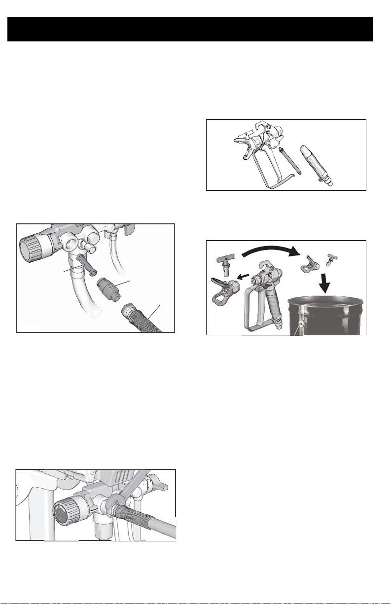
Cleaning InstaClean™ Fluid Filter
(Optional)
The InstaClean Fluid Filter prevents particles
from entering paint hose. After each use,
remove and clean it to ensure peak
performance.
1. Perform Pressure Relief Procedure,
page 13.
2. Disconnect airless spray hose (A) from
sprayer.
3. Unscrew outlet fitting (B).
4. Remove InstaClean Fluid Filter (C).
27179a
Clean the Gun
1. Clean gun fluid filter with water or
flushing fluid and a brush every time you
flush the system. Replace gun filter if
damaged.
ti27494a
2. Remove spray tip and tip guard
assembly and clean with water or
flushing fluid and a brush.
5. Check InstaClean Fluid Filter (C) for
debris. If needed, clean filter with water
or flushing solvent and a soft brush.
a. Install closed (square) end of
InstaClean Fluid Filter (C) in
sprayer.
b. Screw outlet fitting (B) into sprayer.
6. Tighten outlet fitting and reconnect hose
(A) to sprayer. Use wrench to tighten
securely.
ti27122a
3. Wipe paint off outside of gun using a soft
cloth moistened with water or flushing
fluid.
28 3A3212C
Page 29
Storage
ti27232a
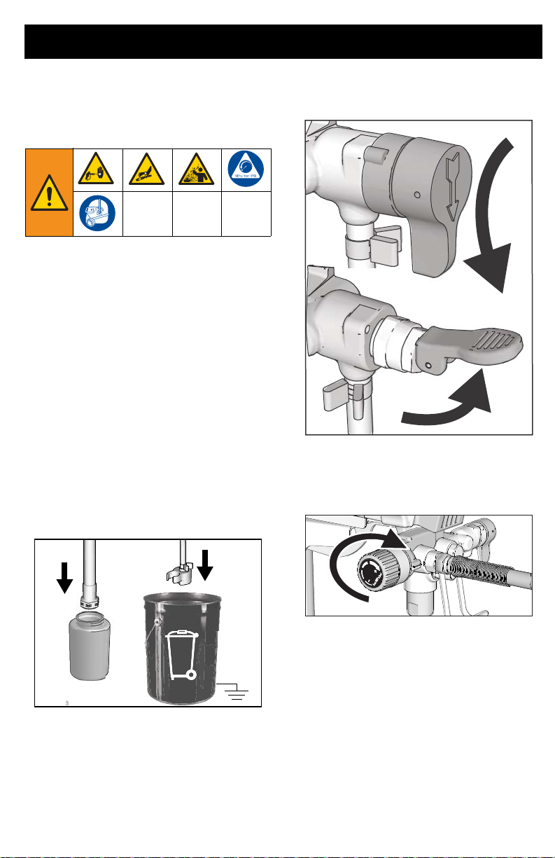
With proper storage, the sprayer will be ready
to use the next time it is needed.
Always circulate Pump Armor storage fluid
through system after cleaning. Water left in
sprayer will corrode and damage pump.
Follow Cleanup, page 22, or
Power Flush, page 24.
• Before storing sprayer make sure all
water is drained out of sprayer and
hoses.
• Do not allow water to freeze in sprayer
or hose.
• Do not store sprayer under pressure.
• Store sprayer indoors.
1. Perform Pressure Relief Procedure,
page 13.
2. On stand models place suction tube in
Pump Armor fluid bottle and drain tube
in waste pail.
Storage
5. Turn ON/OFF switch to ON position.
6. Turn pressure control knob clockwise
until the pump turns on.
7. When storage fluid comes out of drain
tube (5-10 seconds) turn ON/OFF
switch to OFF position.
8. Place Prime/Spray valve in SPRAY
ti27187a
3. On hopper models pour Pump Armor
into the hopper and place drain tube in
waste pail.
4. Place Prime/Spray valve in PRIME
position.
3A3212C 29
position to keep storage fluid in sprayer
during storage.
9. Secure a plastic bag around suction
and drain tube to catch any drips.
ti27188a
Page 30
Reference
413 tip has
fan width.
413 tip has
a 0.013 in.
hole size
Reference
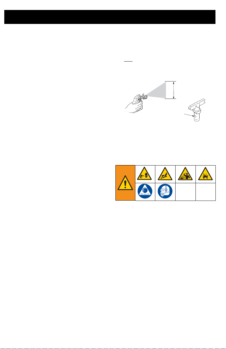
Understanding Tip Number
Spray Tip Selection
Selecting Tip Size
Spray tips come in a variety of hole sizes for
spraying a range of fluids. Your sprayer
includes a tip for use in most paint spraying
applications. Use coatings tables on page 19
to determine the range of recommended tip
hole sizes for each fluid type.
Hints:
As you spray, the tip wears and
•
enlarges. Starting with a tip hole size
smaller than the maximum will allow
you to spray within the rated flow
capacity of the sprayer.
• Use larger tip hole sizes with thicker
coatings and smaller tip hole sizes with
thinner coatings.
• Tips wear with use and need periodic
replacement.
• Tip hole size controls flow rate - the
amount of paint that comes out of the
gun.
Fan Width
Fan width is the size of the spray pattern,
which determines the area covered with each
stroke.
Hints:
•
Select a fan width best suited to the
surface being sprayed.
• Wider fans allow provide better cover-
age on broad, open surfaces.
• Narrower fans provide better control on
small, confined surfaces.
The last three digits of tip number (i.e.:
221413) contain information about hole size
and fan width on surface when gun is held 12
in. (30.5 cm) from surface being sprayed.
First digit when doubled
= approximate
fan width.
Last two digits = tip hole size in thousands of an inch.
8-10 in. (20-25 cm)
Cleaning Fluid Compatibility
Oil- or Water-based Materials
When spraying water-based materi-
•
als, flush the system thoroughly with
water.
• When spraying oil-based materials,
flush the system thoroughly with mineral spirits or compatible, oil-based
flushing fluid.
• To spray water-based materials after
spraying oil-based materials, flush the
system thoroughly with water first. The
water flowing out of drain tube should
be clear and solvent-free before you
begin spraying the water-based material.
30 3A3212C
Page 31
Reference
ti24584a
ti25497a
• To spray oil-based materials after
spraying water-based materials, flush
the system thoroughly with mineral spirits or a compatible oil-based flushing
solvent first. The solvent flowing out of
the drain tube should not contain any
water. When flushing with solvents with
compatible oil-based flushing fluids
always follow Static Grounding
Instructions, page 31.
• To avoid fluid splashing back on your
skin or into your eyes, always aim gun
at inside wall of pail.
Static Grounding Instructions
The equipment must be grounded to
reduce the risk of static sparking and
electric shock. An electric or static spark
can cause fumes to ignite or explode. An
improper ground can cause electric shock.
A good ground provides an escape wire for
the electric current.
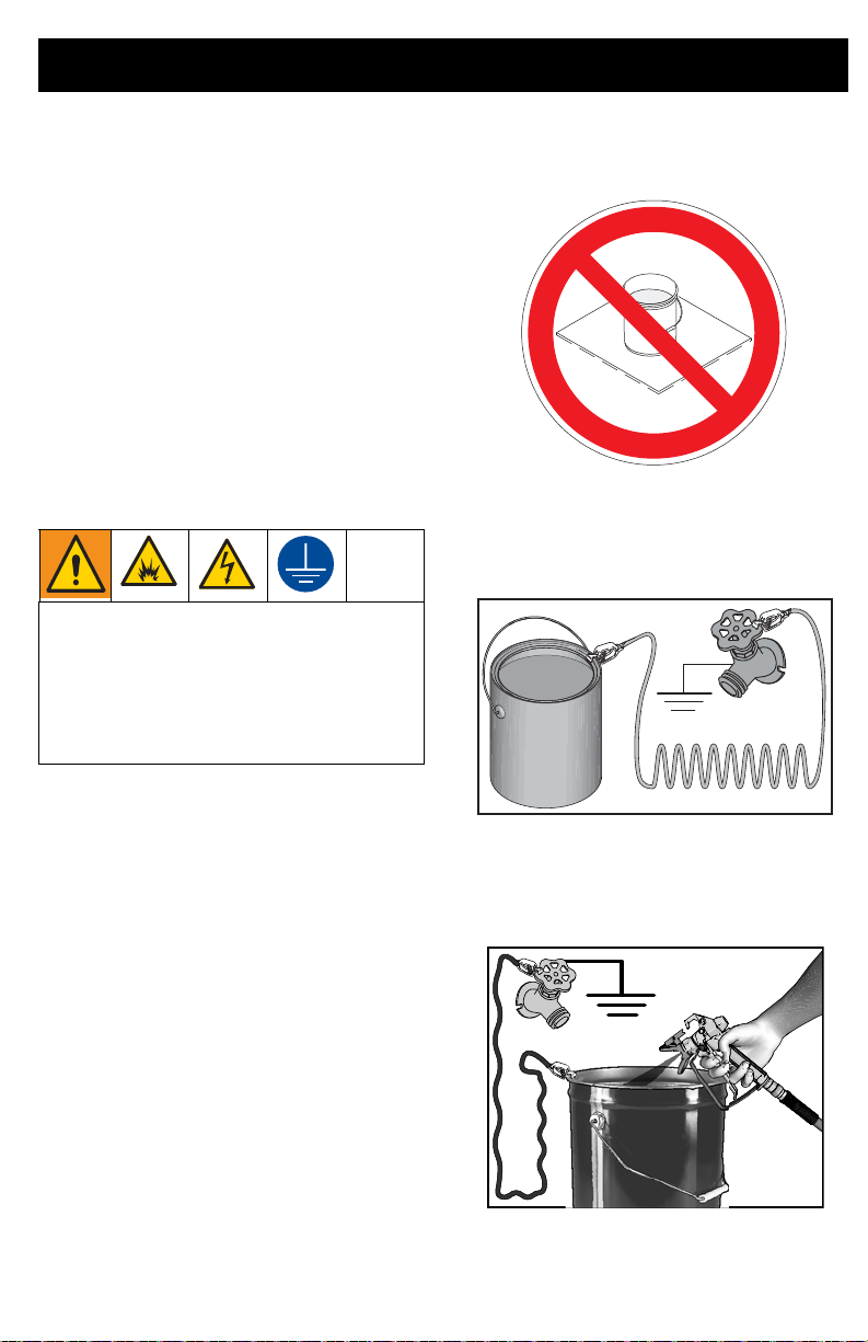
Do not place pail on a non-conductive surface
such as paper or cardboard which interrupts
grounding continuity.
Always ground a metal pail: connect a
ground wire to the pail. Clamp one end to the
pail and the other end to a true earth ground
such as a water pipe.
Always use a metal pail for oil-based
materials requiring flushing with compatible
oil-based flushing fluids when sprayer is
flushed or pressure is relieved.
Follow local code. Use only conductive metal
pails, placed on a grounded surface such as
concrete.
3A3212C 31
To maintain ground continuity when
sprayer is flushed or pressure is relieved
hold metal part of spray gun firmly to the side
of a grounded metal pail, then trigger the gun.
Page 32
Reference
Quick Reference
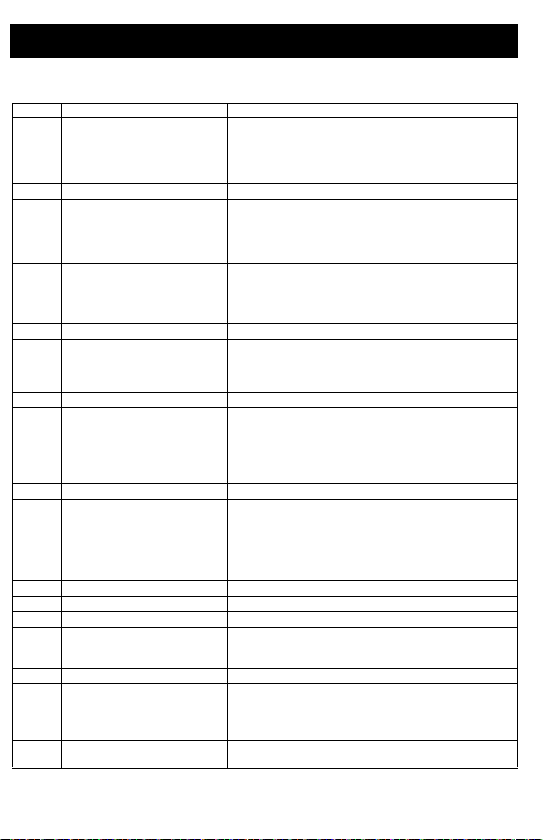
Page 9 Name Description
A Prime/Spray valve • In PRIME position directs fluid to drain tube.
B PushPrime button Taps the inlet ball when pushed to loosen it.
C Pressure control knob Increases (clockwise) and decreases
D ON/OFF switch Turns sprayer ON and OFF.
E Suction tube/Hopper Draws fluid from paint pail into pump.
F Drain tube Drains fluid in system during priming and pressure
G Airless spray gun Dispenses fluid.
H Reversible spray tip
J Tip guard Reduces risk of fluid injection injury.
K Gun trigger lock (page 12) Prevents accidental triggering of spray gun.
L Gun fluid inlet fitting Threaded connection for airless hose.
M Gun fluid filter Filters fluid entering spray gun to reduce tip clogs.
N ProXChange Pump Pumps and pressurizes fluid and delivers it to paint
P Pump fluid outlet fitting Threaded connection for airless hose.
Q Airless hose Transports high-pressure fluid from pump to spray
R InstaClean
S Pail hanger For transporting pail by its handle.
T Inlet strainer Prevents debris from entering pump.
U Power Cord Plugs into power source.
V Easy Access Door Easy Access Door permits quick access to the
W Suction/Drain Tube Cup Holds suction and drain hoses.
X Pump Removal Tool Use cut out in the frame to remove/install pump
Z Inlet Valve Removal Tool Cut out in the frame provide the tools to quickly
Power Flush attachment Connects garden hose to su ction tube for power
™
fluid filter • Filters fluid coming out of pump to reduce tip plug-
• In SPRAY position directs pressurized fluid to
paint hose.
• Automatically relieves system pressure in over-
pressure situations.
(counter-clockwise) fluid pressure in pump, hose,
and spray gun. To select function, align symbol on
pressure control knob with setting indicator, page
13.
relief.
• Atomizes fluid being sprayed, forms spray pattern
and controls fluid flow according to hole size.
• Reverse position unclogs plugged tips without
disassembly.
hose.
gun.
ging and improve
finish.
• Self cleans only during pressure relief.
pump. Open pump door by pulling out on the tabs
while sliding door away from the pump inlet.
packing.
remove/install the inlet valve without additional tools.
flushing water-based fluids.
32 3A3212C
Page 33
Maintenance
1
3
ti27463a
2
Maintenance
Routine maintenance is important to ensure proper operation of your sprayer.
Activity Interval
Inspect/clean InstaClean filter, fluid inlet strainer, and gun
filter.
Inspect motor shroud openings for blockage.
Pump Removal
NOTICE
Protect the internal drive parts of this
sprayer from water. Openings in shroud
allow cooling of mechanical parts and
electronics inside. If water gets into these
openings, the sprayer could malfunction or
be permanently damaged.
Airless Hoses
Check hose for damage every time you
spray. Do not attempt to repair hose if hose
jacket or fittings are damaged. Do not use
hoses shorter than 25 ft (7.6 m). Wrench
tighten, using two wrenches.
On FinishPro sprayers with a hopper the
hopper must be removed before pump can be
removed.
Always perform Pressure Relief Procedure,
page 13 before starting any pump repairs.
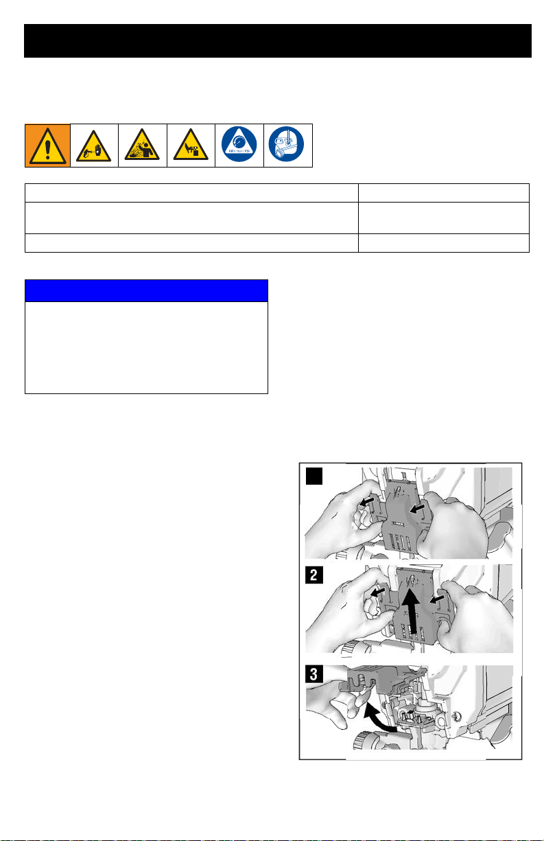
1. Pull tabs on sides of the easy access
door pump towards you while pushing
the entire door away from the inlet end of
the pump.
2. Now lift the door so that it swivels out of
the way.
Daily or each time you spray
Daily or each time you spray
Spray Tips
• Always clean tips with compatible
cleaning fluid and brush after spraying.
• Tips may require replacement after 15
gallons (57 liters) or they may last
through 60 gallons (227 liters) depending on abrasiveness of paint.
Pump Repair
When pump packings wear, paint will begin
to leak down outside of pump.
• Purchase a pump repair kit and install
according to instructions provided with
kit, before your next job.
• See Pump Assembly, page 46 or con-
sult a Graco/M
retailer, distributor, or service center.
3A3212C 33
AGNUM authorized
Page 34
Maintenance
ti26931a
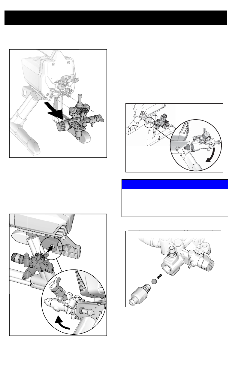
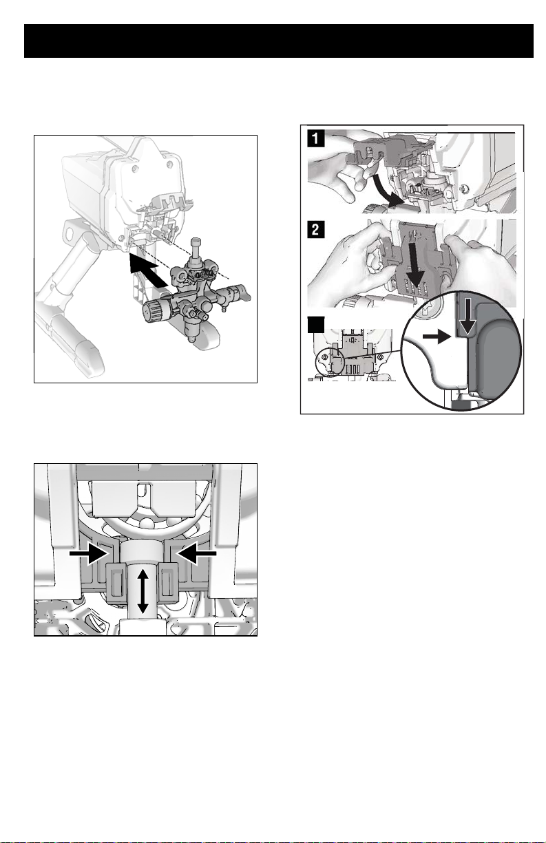
3. Slide pump assembly off the mounting
pins.
ti26930a
ProXChange Removal Tool
An integrated tool is included in the frame to
remove the ProXChange packing assembly.
See Pump repair manual for complete repair
instructions.
Inlet Valve Removal
An integrated tool is included in the frame to
remove the inlet valve assembly from the
pump. If you suspect that the inlet valve is
clogged or stuck, remove the valve assembly
and clean or replace.
1. Remove suction tube or hopper from
sprayer.
2. Insert pump inlet into frame and loosen
the inlet valve. Remove inlet valve.
ti27479a
NOTICE
Do not lose the ball and spring inside the inlet
valve assembly. It may fall out when the inlet
valve is removed. Pump will not prime without
the ball and spring.
ti27498a
3. Clean any debris and dried pain t from
the cavity and replace the ball and
spring. Tighten inlet valve to pump
using integrated tool on the frame.
34 3A3212C
Page 35
Maintenance
1
ti27478a
2
3
Pump Installation
1. Slide pump assembly onto the mounting
pins.
ti27036a
2. Move pump displacement rod up or
down until cap is level with the opening
in the yoke.
3. Swing easy access door pump door
closed while pushing the entire do or
towards the inlet end of the pump.
NOTE: Door must be fully closed and
latched before sprayer will operate.
ti27037a
3A3212C 35
Page 36
Troubleshooting
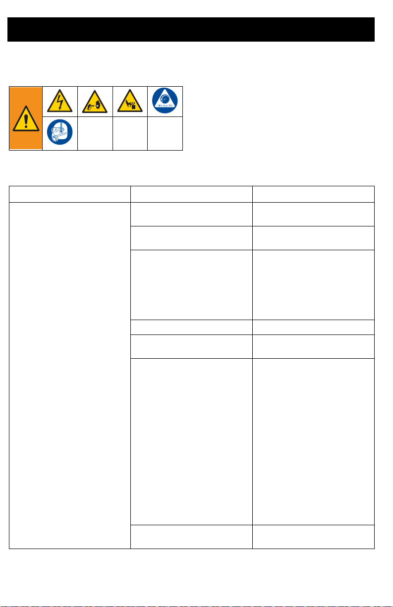
Troubleshooting
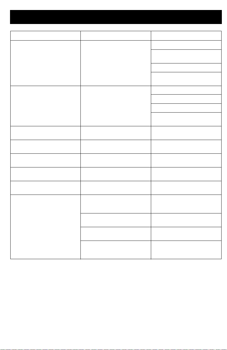
Problem Cause Solution
1. Follow Pressure Relief Procedure,
page 13, before checking or repairing.
2. Solutions at the beginning of each problem listed are the most common, Start
at the beginning and continue down the
list to find a solution.
3.
Check everything in this Troubleshooting
Table before you bring the sprayer to an
authorized service center.
Motor does not run:
(verify sprayer is plugged in, and
power switch is on)
Easy access door not fully closed. Verify that easy access door is closed
Pressure control knob is set at zero
pressure.
Electric outlet is not providing power. Test outlet with known working
Extension cord is damaged. Replace extension cord. See page 5.
Sprayer electric cord is damaged. Check for broken insulation or wires.
Pu mp is se iz ed
(Paint has hardened in pump
or
Water is frozen in pump.)
Motor or control is damaged. Consult a Graco/ Magnum authorized
and latched. See page 35.
Turn pressure control knob clockwise
to increase pressure setting.
device.
Reset circuit breaker or replace fuse.
Find working outlet.
Reset building circuit breaker or
replace fuse.
Replace electric cord if damaged.
Turn ON/OFF switch off and unplug
sprayer from outlet.
If frozen do NOT try to start sprayer
until it is completely thawed or it may
damage the motor, control board
and/or drive train.
Place sprayer in warm area for
several hours. Check for free moving
pump by removing shroud and
spinning fan.
If not frozen, check for hardened paint
in pump. If paint has hardened in
pump. See page 33.
If motor does not turn with pump
removed, consult a Graco/ Magnum
authorized retailer, distributor, or
service center.
retailer, distributor, or service center.
36 3A3212C
Page 37
Troubleshooting
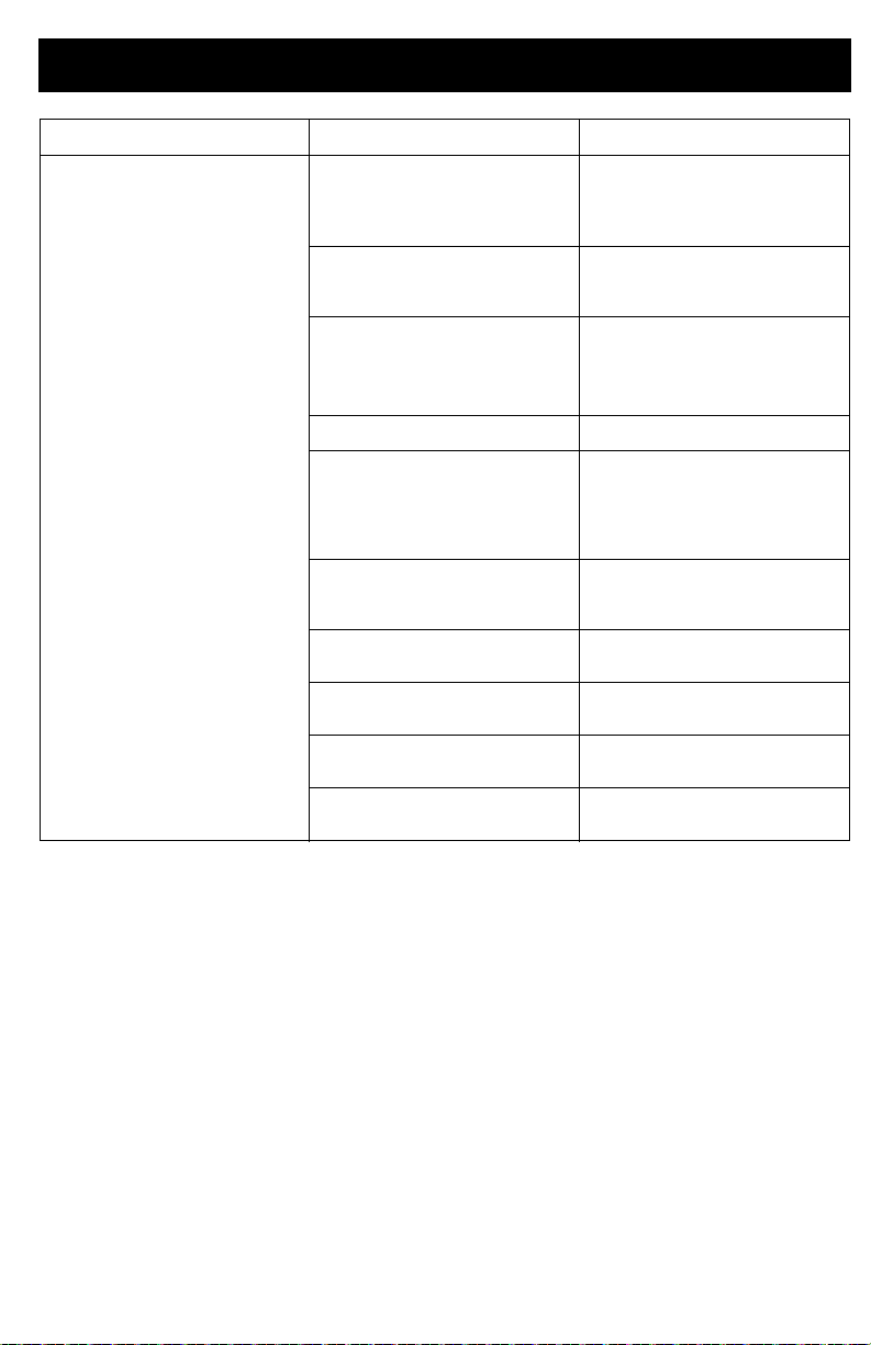
Problem Cause Solution
Sprayer runs, but pump does not
prime or looses prime while in use.
(Pump cycles but does not pump
paint or build pressure.)
Inlet valve check ball is stuck. Press PushPrime button to dislodge
Prime/Spray Valve is in SPRAY
position.
Pump was not primed with flushing
fluid.
(Thick fluids may not prime if not
initially primed with flushing fluid.)
Debris in paint. Strain the paint. See page 12.
Thick or “sticky” paint. Some fluids may prime faster if the
Inlet strainer is clogged or suction
tube is not immersed in paint.
Inlet valve check ball or seat is dirty. Remove inlet fitting. Clean or replace
Suction tube is leaking. Inspect suction tube connection for
Outlet valve check ball is stuck. Unscrew outlet valve, remove, and
Prime/Spray Valve is worn or
obstructed with debris.
the ball allowing pump to prime
properly, OR Power Flush sprayer,
see page 24.
Turn Prime/Spray Valve down to
PRIME position until paint exits drain
tube. The pump is now primed.
Remove suction tube from paint.
Prime pump with oil or water-based
flushing fluid. See page 14.
ON/OFF switch is momentarily turned
off so the pump can slow and stop.
Turn ON/OFF switch on and off
several times if necessary.
Clean debris off inlet strainer and
make sure suction tube is immersed
in paint.
ball and seat. See page 34.
cracks or vacuum leaks.
clean assembly.
Take sprayer to Graco/MAGNUM
authorized service center.
3A3212C 37
Page 38
Troubleshooting
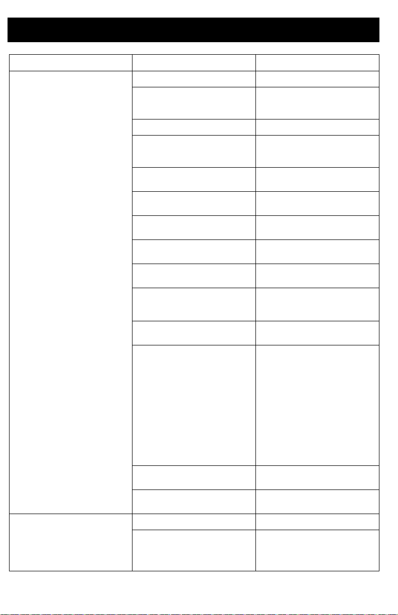
Problem Cause Solution
Pump is primed, but can not achieve
good spray pattern.
Spray gun stopped spraying while
trigger is pulled.
Spray tip may be partially clogged. Clear spray tip clog. See page 21.
Reversible spray tip is in UNCLOG
position.
Debris in paint. Strain the paint. See page 12.
Pressure is set too low. Align pressure control knob setting
InstaClean fluid filter is clogged. Clean or replace InstaClean fluid
Spray gun fluid filter is clogged. Clean or replace gun fluid filter. See
Spray tip selected is too large for
capability of sprayer.
Spray tip is worn beyond the
capability of sprayer.
Spray tip gasket and seal worn or
missing.
Inlet strainer is clogged or suction
tube is not immersed in paint.
Extension cord is too long or not
heavy enough gauge.
Inlet pump valve or outlet pump valve
is worn or clogged with debris.
Material is too thick. Thin material. Follow manufacturers
Airless hose is too long (if extra
section was added).
Spray tip is clogged. Clear spray tip clog. See page 21.
Sprayer lost prime. See troubleshooting section “Sprayer
Rotate arrow-shaped handle on spray
tip so it points forward to SPRAY
position. See page 21.
indicator to desired spray setting. See
page 19.
filter. See page 28.
page 28.
Replace tip. See page 19.
Replace tip. See page 19.
Replace gasket and seal. See page
18.
Clean debris off inlet strainer and
make sure suction tube is immersed
in paint.
Replace extension cord. See page 5.
Check for worn or contaminated inlet
valve or outlet valve.
- Prime sprayer with paint
- Trigger gun momentarily
- When trigger is released, pump
should cycle momentarily and stop
- If pump continues to cycle, pump
valves may be worn or contaminated
with debris
- Clean or replace valves with
appropriate kits. See page 46.
recommendations.
Remove section of airless hose.
runs, but pump does not prime or
looses prime while in use.” on page
37.
38 3A3212C
Page 39
Troubleshooting
Problem Cause Solution
When paint is sprayed, it runs down
the wall or sags.
When paint is sprayed, coverage is
inadequate.
Fan pattern varies dramatically while
spraying.
Cannot trigger spray gun. Spray gun trigger lock is engaged. Rotate trigger lock to disengage
Paint is coming out of pressure
control.
Paint is leaking through drain tube. Sprayer is over pressurizing. Take sprayer to Graco/M
Paint leaks down outside of pump. Pump packings are worn. Replace pump packings with new
Motor is hot and runs intermittently.
Motor automatically shuts off due to
excessive heat. Damage can occur if
cause is not corrected.
Material is going on too thick. Move gun faster.
Choose a spray tip with smaller hole
size.
Choose spray tip with wider fan.
Make sure gun is far enough from
surface.
Material is going on too thin. Move gun slower.
Choose spray tip with larger hole size.
Choose spray tip with narrower fan.
Make sure gun is close enough to
surface.
Pressure control switch is worn and
causing excessive pressure variation.
Pressure control is worn. Take sprayer to Graco/M
Vent holes in enclosure are plugged
or sprayer is covered.
Extension cord is too long or not a
heavy enough gauge.
Unregulated electrical generator
being used has excessive voltage.
Motor needs to be replaced. Take sprayer to Graco/Magnum
Take sprayer to Graco/M
authorized service center.
trigger lock. See page 12.
authorized service center.
authorized service center.
ProXChange module. See page 33.
Keep vent holes clear of obstructions
and overspray and keep sprayer open
to air.
Replace extension cord. See page 5.
Use electrical generator with a proper
voltage regulator.
authorized retailer, distributor, or
service center.
AGNUM
AGNUM
AGNUM
3A3212C 39
Page 40
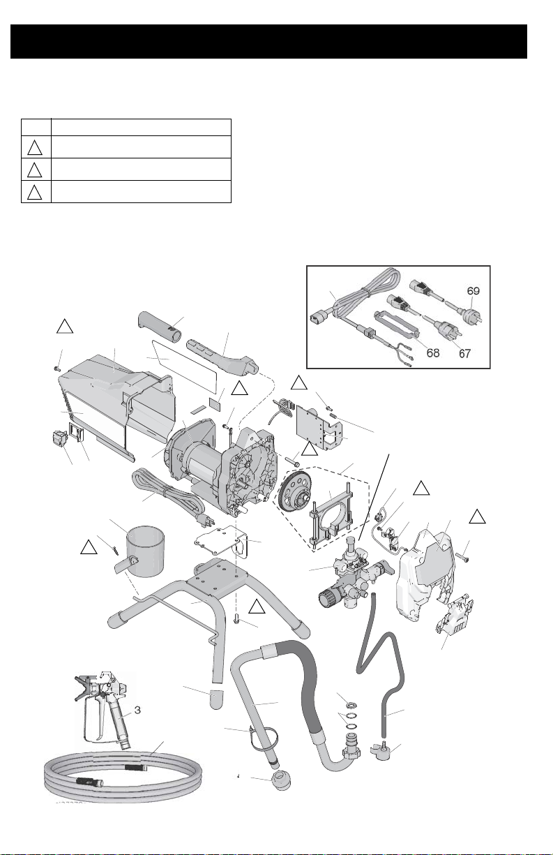
17H211, 17H214 Stand Sprayers
3
1a
1
2
5
7
8
9
10
10b
10c
27
9
12
10a
13
15
15a
16
17
18
28
24
72
56
25
19
20
22
23
43
45
6
46
49
26
50
47
48
31
30
3
69
68
67
ti27270a
44
See page 46.
2
2
2
2
3
3
2
1
Ref. Torque
140-160 in-lb (16 - 18 N•m)
30-35 in-lb (3.5 - 4.0 N•m)
110-120 in-lb (12 - 14 N•m)
1
2
3
17H211, 17H214 Stand Sprayers
40 3A3212C
Page 41

17H211, 17H214 Stand Sprayers
17H211, 17H214 Stand Sprayers Parts List
Part Description
Part Description
Ref.
1 KIT, motor includes 1a
17F756 120V, Model 17H211
17F758 230V, Model 17H214
1a KIT, fan
287770 120V, Model 17H211
16X980 230V, Model 17H214
2 17J863 KIT, gear and yoke
3 CORD, power
17J173 120V, Model 17H211
17J405 230V, Model 17H214
5 17J864 KIT, yoke 1
6 117493 SCREW, mach, hwhd
7 17J875 PUMP, displacement
17J865 SHIELD, motor
8
9 118444 SCREW, mach, hwhd
10 17J866 KIT, cover, front
10a 17F233 COVER, pump,
10b 17F262 COVER, wire
10c 128551 CABLE, PC, jumper
12 115478 SCREW, mach, Torx,
13 15J803 SWITCH, bracket
15 KIT, control includes
17J867 120V, Model 17H211
17J885 230V, Model 17H214
15a 119276 FUSE, 12.5A slow
16 117501 SCREW, plastite
17 118899 SWITCH, rocker
18 115498 SCREW, mach, slot,
19 17G329 PLATE, motor, mount 1
20 15E823
22 260212 SCREW, hwh, thread
23 15G857 CAP, leg 4
24 276864 HANDLE, sprayer 1
25 116139 GRIP, handle 1
26 17J883 TUBE, suction,
3A3212C 41
includes 5
includes 9, 56
10-24 x 0.5 in.
includes 9, 10a, 10b,
10c,12
locking
pan hd
15a, 16
blow
hex whd
FRAME, standmount 1
forming
assembly includes 47,
49, 50
Qty.
Ref.
27 17J025 LABEL, front 1
30 HOSE, cpld, 1/4 in. x
1
1
1
1
1
1
1
1
1
1
3
1
1
1
1
4
240794
247340
31
288430 Model 17H211 1
246506 Model 17H214 1
43 122667 SCREW, drill, HWH
44 17J884 TUBE, drain includes
15G838 CUP, suction/drain 1
45
46 244035 DEFELCTOR, barbed 1
47 276897
48 404989 STRAP, tie 1
49 115099 WASHER, hose 1
50 117559 O-ring 2
56 LABEL, warning
17J027 Model 17H211 1
17K017 Model 17H214 1
57 CARD, medical alert
222385 EN, ES, FR 1
17A134 EN, ZH, KO 1
67 242001 CORDSET, EU Model
68 195551 RETAINER, plug
69 242005 CORDSET, AU Model
1
72 17J026 LABEL, side, GX 19 1
Replacement Danger and Warning labels,
1
1
tags, and cards are available at no cost.
50 ft
Model 17H211 1
Model 17H214 1
GUN, spray, SG3
46, 48
STRAINER, 7/8-14 1
(not shown)
17H214
Model 17H214
17H214
1
1
1
1
4
1
Qty.
1
1
1
1
1
Page 42
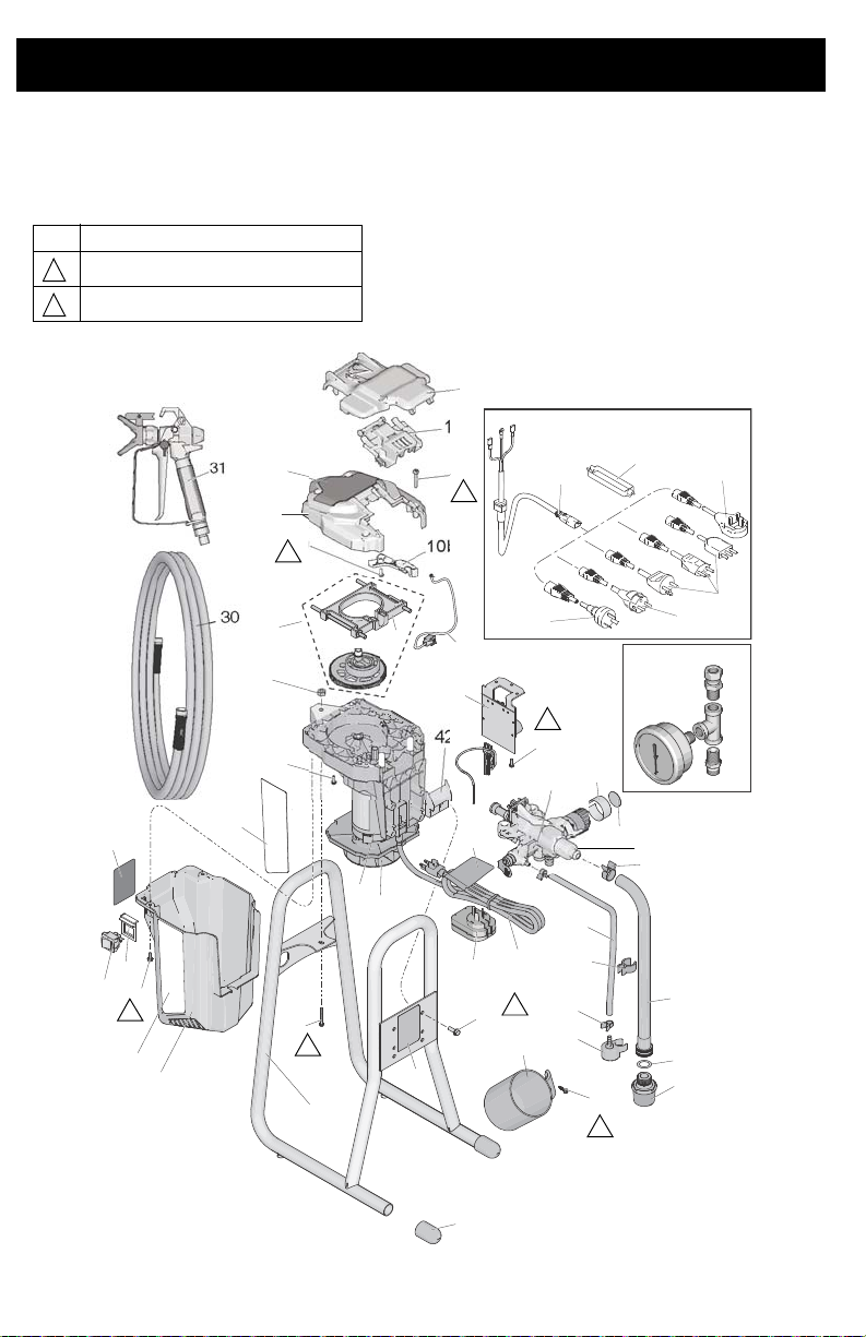
24Y680, 17G183, 17H218, 17H219, 17H221
Ref. Torque
30-35 in-lb (3.5 - 4.0 N•m)
110-120 in-lb (12 - 14 N•m)
2
3
ti27281a
27
26
1
1a
48
2
5
8
25
3
58
68
67
71
69
70
3
42
7
9
10b
10c
9
12
13
15
45
16
17
19
22
21
34
29
33
20
24
24a
24e
24c
24b
24d
18
49
66
47
46
10
10a
30
31
14
56
See page 46.
3
2
2
2
3
2
2
24Y680, 17G183, 17H218, 17H219, 17H221 DI Stand Sprayers
42 3A3212C
Page 43

24Y680, 17G183, 17H218, 17H219, 17H221
24Y680, 17G183, 17H218, 17H219, 17H221 DI Stand
Sprayers
Ref. Part Description Qty.
1 KIT, motor includes 1a
17K684 120V, Model 24Y680 1
17L083 230V, Models 17G183,
1a 16X980 KIT, fan 1
2 17J869 KIT, gear and yoke
3CORD, power
17J173 120V, Model 24Y680 1
17J174 230V, Model 17H219 1
17J175 230V, Model 17G183 1
17J405 230V, Model 17H218,
5 17J864 KIT, yoke 1
7 17J908 PUMP, displacement 1
8 SHIELD, motor includes 9,
17K688 Model 24Y680, 17H219,
17L101 Models 17G183, 17H218 1
9 118444 SCREW, mach, hwhd
10 17J866 KIT, cover, frt includes 9,
10a 17F233 COVER, pump, locking 1
10b 17F262 COVER, wire 1
10c 128551 CABLE, PC, jumper
12 115478 SCREW, mach, Torx, pan hd4
13 SWITCH, bracket
15J803 Models 24Y680, 17H219,
15X737 Models 17G183, 17H218 1
14 17J618
15
17J867 120V, Model 24Y680 1
17J885 230V, Models 17G183,
15a 119276 FUSE, 12.5A slow blow 1
16 117501 SCREW, plastite 1
17 118899
18 115498
19 17F940
20 15G857
15G838 CUP, suction/drain 1
21
22 128795 SCREW, hwh, thread
24 17D161 TUBE, suction, assembly
24a 195108 TUBE, drain 1
Parts List
17H218, 17H219, 17H221
includes 5
17H221
56
17H221
10-24 x 0.5 in.
10a, 10b, 10c, 12
17H221
SHIELD, paint 1
KIT, control includes 15a,
16
17H218, 17H219, 17H221
SWITCH, rocker 1
SCREW, mach, slot, hex
whd
FRAME, direct immersion 1
CAP, leg 2
forming
includes 24a-24e, 46, 47
Ref. Part Description Qty.
24b 116295 CLAMP, tube 1
24c 195400 CLIP, tube 1
24d 115489 CLAMP, drain tube 2
1
24e 115099 WASHER, hose 1
25 17J029 LABEL, right 1
26 17J030 LABEL, left 1
1
27 17J028 LABEL, front 1
30 247340 HOSE, cpld, 1/4 in. x 50 ft 1
31
17J910 Models 24Y680, 17G183,
1
1
3
1
1
16X214 Model 17H219 1
34 122667 SCREW, drill, HWH 1
17J444 STRAP, carry 1
41
17J277 TRAY, drip 1
42
45 245856 KIT, gauge, pressure
46 244035 DEFLECTOR, barbed 1
47 288716
48 120736 SCREW, hex, flange 1
49 102040 NUT, lock, hex 1
56 LABEL, warning
17K018 Models 24Y680, 17H221 1
16G596 Models 17G183, 17H218 1
17K016 Model 17H219 1
57 CARD, medical alert (not
GUN, spray
17H218, 17H221
Models 17G183, 17H218
STRAINER 1
shown)
222385 EN, ES, FR 1
17A134 EN, ZH, KO 1
58 LABEL, warning cord
1
1
1
4
1
17K020 Models 24Y680, 17H221 1
15H087 Model 17H219 1
66 127442 PLUG, converter, Models
17H219
67 242001 CORDSET, EU Model
17H218, 17H221
68 195551 RETAINER, plug Model
17H218, 17H221
69 287121 CORDSET, Italy/
Denmark/Sweden Model
17H218
70 17J242 CORDSET, UK Model
17H218
71 242005 CORDSET, AU, Model
17H221
Replacement Danger and Warning labels,
tags, and cards are available at no cost.
1
1
1
1
1
1
1
1
3A3212C 43
Page 44
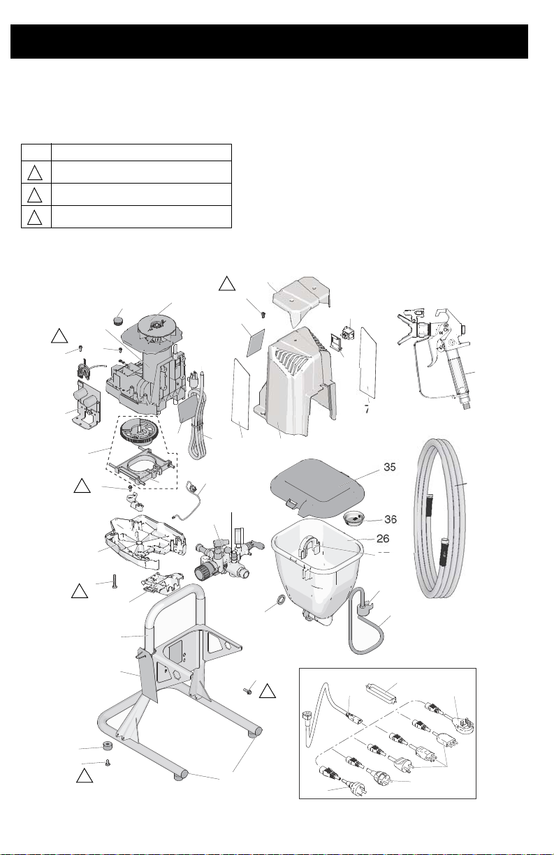
17F924, 17G184, 17H222, 17H223 Hopper
Ref. Torque
15-20 in-lb (1.5 - 2 N•m)
30-35 in-lb (3.5 - 4.0 N•m)
110-120 in-lb (12 - 14 N•m)
1
2
3
2
5
10
10b
10c
12
9
10a
16
15
25
9
23
7
35
37
26
22
18
57
20
38
39
27
1
1a
3
58
ti27282a
36
26a
9
8
24
17
71
72
13
56
68
67
66
69
70
3
30
31
3
1
3
2
2
2
See page 46.
17F924, 17G184, 17H222, 17H223 Hopper Sprayers
44 3A3212C
Page 45

17F924, 17G184, 17H222, 17H223 Hopper
17F924, 17G184, 17H222, 17H223 Hopper Sprayers
Parts List
Part Description
Part Description
Ref.
1 KIT, motor includes 1a
17F757 120V, Model 17F924 1
17F758 230V, Models 17G184,
1a 16X980 KIT, fan 1
2 17J863 KIT, gear and yoke
3CORD, power
17J173 Model 17F924 1
17J175 Model 17G184 1
17J405 Model 17H222, 17H223 1
5 17J864 KIT, yoke 1
7 17J909 PUMP, displacement
17J887 SHIELD, motor includes
8
9 118444 SCREW, mach, hwhd
10 17J866 KIT, cover, front includes
10a 17F233 COVER, pump, locking 1
10b 17F262 COVER, wire 1
10c 128551 CABLE, PC, jumper
12 115478 SCREW, mach, Torx,
13 15X737 SWITCH, bracket
15 KIT, control includes 15a,
17J867 120V, Model 17F924 1
17J885 230V, Models 17G184,
15a 119276 FUSE, 12.5A slow blow 1
16 117501 SCREW, plastite
17 118899 SWITCH, rocker
18 115498 SCREW, mach, slot,
20 17H426 FRAME, hopper 1
22 128795 SCREW, hwh, thread
23 120151 RETAINER, caplug 2
24 17H593 COVER, shroud 1
25 17K640 DAMPENER, feet 4
26 17J244 ASSEMBLY, hopper
26a 11509 9 WASHER, hose 1
27 17J819 PLUG 1
17H222, 17H223
includes 5
9, 56
10-24 x 0.5 in.
9, 10a, 10b, 10c, 12
pan hd
16
17H222, 17H223
hex whd
forming
includes 26a, 35
Qty.
Ref.
30 214698 HOSE, cpld, 3/16 in. x
1
31 17J261 GUN, spray, FTX
35 17H417 LID, hopper 1
36 112133 SCREEN, hopper
1
37 17H419 CLIP, drain hos e
38 244035 DEFLECTOR, barbed 1
39 17K336 TUBE, drain includes
56 LABEL, warning
17J912 Model 17F924 1
1
1
7
1
1
4
1
1
1
1
1
4
1
16G596 Models 17G184,
17K016 Model 17H223 1
57 CARD, medical alert (not
222385 EN, ES, FR 1
17A134 EN, ZH, KO 1
58 LABEL, warning, cord
15H085 Model 17F924 1
15H087 Model 17H223 1
66 242005 CORDSET, AU Model
67 242001 CORDSET, EU Model
68 195551 RETAINER, plug Model
69 287121 CORDSET, Italy/
70 17J242 CORDSET, UK Model
71 LABEL, left side
17F947
17J041
72 LABEL, right side
17F946
17J039
Replacement Danger and Warning labels,
tags, and cards are available at no cost.
25ft
37, 38
17H222
shown)
17H223
17H222 ,17H223
17H222, 17H223
Denmark/Sweden Model
17H222
17H222
Models 17F924,
17H223
Models 17G184,
17H222
Models 17F924,
17H223
Models 17G184,
17H222
Qty.
1
1
1
1
1
1
1
1
1
1
1
1
1
1
1
3A3212C 45
Page 46
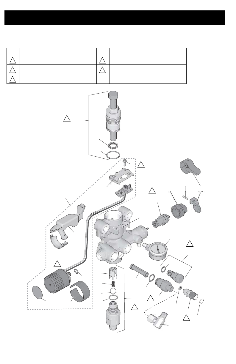
Pump Assembly
Ref. Torque Ref. Torque
140-160 in-lb (16 - 18 N•m) 220-250 in-lb (25 - 28 N•m)
270-330 in-lb (30 - 37 N•m) 320-380 in-lb (36 - 43 N•m)
30-35 ft-lb (40 - 48 N•m)
1
4
253
1
28a
28b
6
4
6a
2
3
8
9
10
25
30
16
28
28c
21
7
7a
44
5
15
14
13
12
42
43
ti27488a
29
11
7b
4
2
1
4
5
4
5
3
Pump Assembly
46 3A3212C
Page 47

Pump Parts List
i
Part Description
Ref.
1 17G447 HOUSING, pump
2 17D364 GUIDE, ball
3 128336 SPRING, compression
4 105445 BALL, 0.5 in. 1
5 117501 SCREW, mach, slot
6 KIT, inlet housing
17J876 Models 24Y680,
17J877 Models 17H211,
17J924 Models 17F924,
6a 124582 PACKING, O-ring 1
7 17J878 KIT, PushPrime
7a 16P303 PACKING, O-ring 1
7b 17K420 LABEL, PushPrime
8
235014 Models 17H211,
17J925 Models 24Y680,
9 BASE, valve
224807 Models 17H211,
10 HANDLE, valve, drain
187625 Models 17H211,
15Y185 Models 24Y680,
11 111600 PIN, grooved Models
HWH
includes 2, 3, 4, 6a
17G183, 17H218,
17H219, 17H221
17H214
17G184, 17H222,
17H223
includes 7a, 7b
KIT, valve, drain,
includes 9, 10, 11
17H214
17F924, 17G183,
17G184, 17H218,
17H219, 17H221,
17H222, 17H223
17H214
17H214
17F924, 17G183,
17G184, 17H218,
17H219, 17H221,
17H222, 17H223
includes 11
17H211, 17H214
Qty.
Pump Assembly
Part Description
Ref.
12 288747 KIT, filter (Not installed
1
1
13 120776 PACKING, O-ring
1
14 24Y327 KIT, repair outlet
2
15 17J880 KIT, outlet valve repair
16 128323 SPRING, valve
21 16D531 PACKING, O-ring
1
25 24Y472 KIT, repair, piston pump
28 KIT, pressure control
1
1
17J881 Models 17H211,
17J927 Models 24Y680,
1
1
28a 15A464 LABEL, control
28b 17C831 LABEL, control
28c 106555 O-ring 1
1
29 17F227 BRACKET, electrical
1
30 KIT, shield, wire
17F229 Models 17H211,
17J882 Models 24Y680,
1
42 122486 PACKING, O-ring 1
1
43 16X147 GAUGE, pressure
1
44 155541 FITTING, swivel
1
on all models.)
includes 12, 13
includes 42
includes 16, 21
includes 5, 28a, 28b,
28c, 29, 30
17H214
17F924, 17G183,
17G184, 17H218,
17H219, 17H221,
17H222, 17H223
connector
17H214
17F924, 17G183,
17G184, 17H218,
17H219, 17H221,
17H222, 17H223
Models 17F924,
17G184, 17H222,
17H223
Models 17F924,
17G184, 17H222,
17H223
Qty.
1
1
1
1
1
1
1
1
1
1
1
1
1
1
1
1
3A3212C 47
Page 48
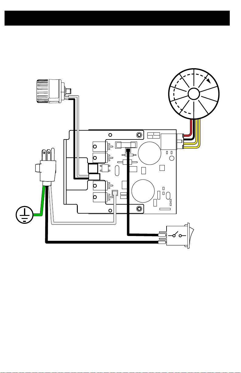
Wiring Diagrams
M
Wiring Diagrams
110/120V
ti27233a
48 3A3212C
Page 49
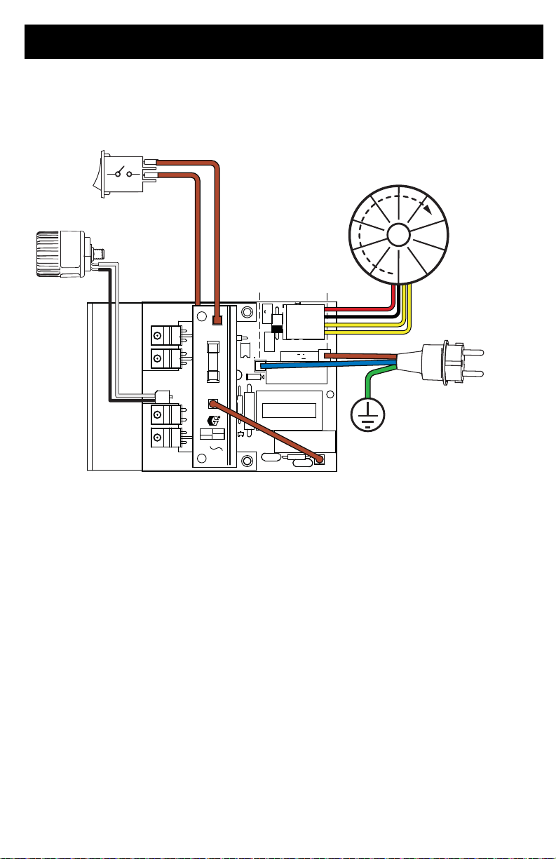
230V
ti27485a
M
Wiring Diagrams
3A3212C 49
Page 50
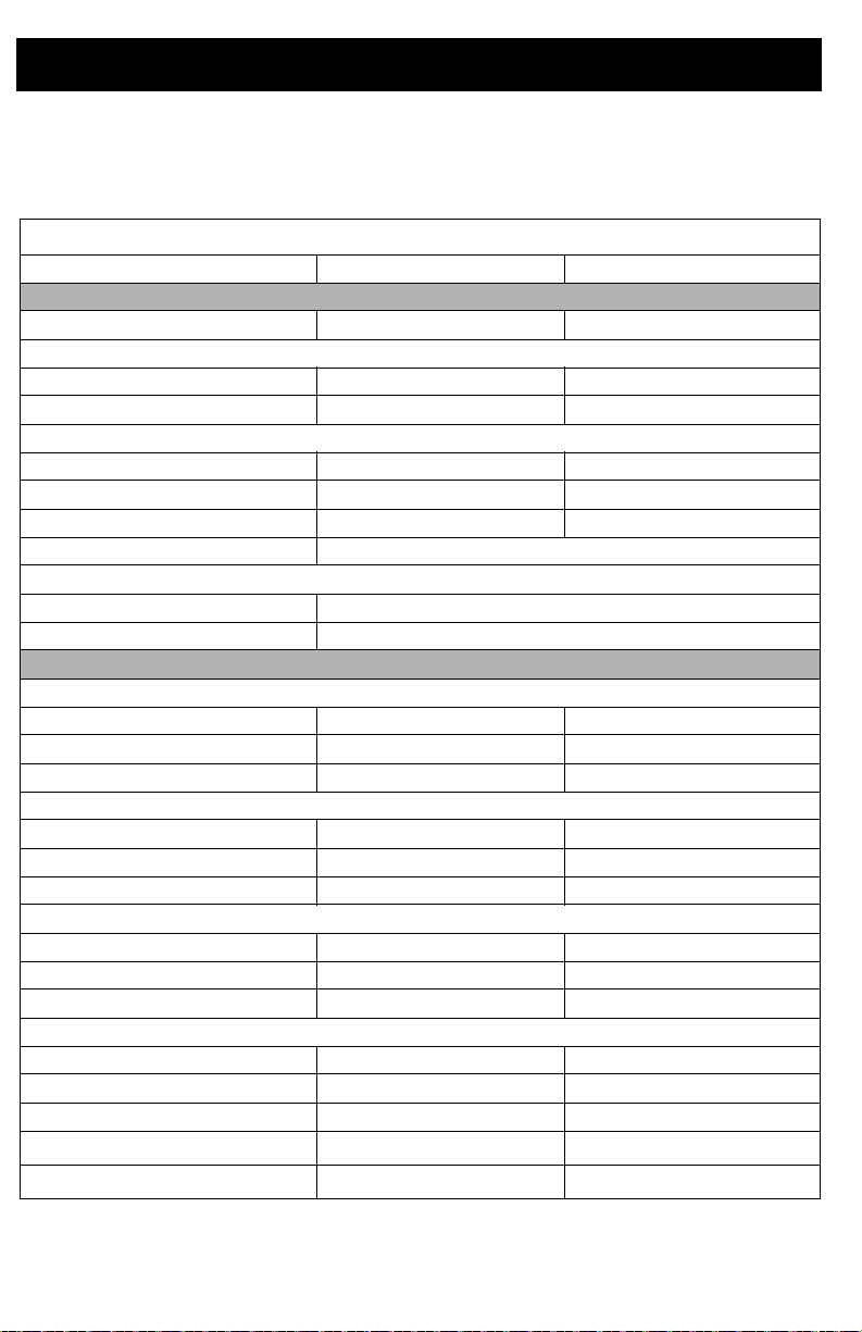
Technical Specifications
Technical Specifications
GX 19, GX 21, FinishPro GX 19
GX 19, GX 21, FinishPro GX 19
US Metric
Sprayer
Maximum fluid working pressure 3000 psi 207 bar, 20.7 MPa
Maximum Delivery
GX 19/FinishPro GX 19 0.38 gpm 1.4 lpm
GX 21 0.47 gpm 1.8 lpm
Maximum Tip Size
GX 19/FinishPro GX 19 0.019 in. 0.048 mm
GX 21 0.021 in. 0.053 mm
Fluid Outlet npsm 1/4 in. 1/4 in.
Generator Minimum 3500 W
Power Requirements
GX 19
GX 21
Dimensions
Height
Stand
DI Stand 22 in. 55.9 cm
Hopper
Length
Stand
DI Stand
Hopper
Width
Stand
DI Stand
Hopper 13.5 in. 34.3 cm
Weight
Stand
DI Stand 29 lb. 13.2 kg
Hopper
Storage temperature range
Operating temperature range
110–120V, 8 A / 220–240V, 5 A
110–120V, 12 A / 220–240V, 10 A
18.4 in. 46.7 cm
19.6 in. 49.8 cm
16.7 in. 47.5 cm
18.4 in. 46.7 cm
20.2 in. 51.3 cm
13.5 in. 34.3 cm
12 in. 30.5 cm
25 lb. 11.3 kg
28 lb. 12.1 kg
–30° to 160°F
–35° to 71°C
40° to 115°F
4° to 46°C
50 3A3212C
Page 51
Technical Specifications
GX 19, GX 21, FinishPro GX 19
US Metric
Noise**
Sound pressure 83 dBa*
Sound power 93 dBa*
Materials of Construction
Wetted materials on all models stainless steel, brass, leather, ultra-high molecular weight
polyethylene (UHMWPE), carbide, nylon, aluminum, PVC,
polypropylene, fluoroelastomer
Notes
* Startup pressures and displacement per cycle may vary based on suction condition,
discharge head, air pressure, and fluid type.
** Sound pressure measured 3 feet (1 meter) from equipment. Sound power measured per
ISO-9614.
When pump is stored with non-freezing fluid. Pump damage will occur if w ater or latex
paint freezes in pump.
Damage to plastic parts may result if impact occurs in low temperature conditions.
Changes in paint viscosity at very low or very high temperatures can affect sprayer
performance.
3A3212C 51
Page 52
Technical Specifications
GX FF
GX FF
US Metric
Sprayer
Maximum fluid working pressure 3000 psi 207 bar, 20.7 MPa
Maximum Delivery 0.38 gpm 1.4 lpm
Maximum Tip Size 0.019 in. 0.048 mm
Fluid Outlet npsm 1/4 in. 1/4 in.
Generator Minimum 1500 W
Power Requirements
Dimensions
Height
Length
Width 13.5 in. 34.3 cm
Weight
Storage temperature range
Operating temperature range
Noise**
Sound pressure 83 dBa*
Sound power 93 dBa*
Materials of Construction
Wetted materials on all models stainless steel, brass, leather, ultra-high molecular weight
polyethylene (UHMWPE), carbide, nylon, aluminum, PVC,
polypropylene, fluoroelastomer
Notes
* Startup pressures and displacement per cycle may vary based on suction condition,
discharge head, air pressure, and fluid type.
** Sound pressure measured 3 feet (1 meter) from equipment. Sound power measured per
ISO-9614.
When pump is stored with non-freezing fluid. Pump damage will occur if wate r or latex
paint freezes in pump.
Damage to plastic parts may result if impact occurs in low temperature condition s .
Changes in paint viscosity at very low or very high temperatures can affect sprayer
performance.
110–120V, 8 A / 220–240V, 5 A, 1Ø
19.6 in. 49.8 cm
20.2 in. 51.3 cm
31 lb. 14.1 kg
–30° to 160°F
–35° to 71°C
40° to 115°F
4° to 46°C
52 3A3212C
Page 53

Graco Standard Warranty
Graco Standard Warranty
Graco warrants all equipment referenced in this document which is manufactured by Graco and bearing
its name to be free from defects in material and workmanship on the date of sale to the original purchaser
for use. With the exception of any special, extended, or limited warranty published by Graco, Graco will,
for a period of twelve months from the date of sale, repair or replace any part of the equipment
determined by Graco to be defective. This warranty applies only when the equipment is installed,
operated and maintained in accordance with Graco’s written recommendations.
This warranty does not cover, and Graco shall not be liable for general wear and tear, or any malfunction,
damage or wear caused by faulty installation, misapplication, abrasion, corrosion, inadequate or
improper maintenance, negligence, accident, tampering, or substitution of non-Graco component parts.
Nor shall Graco be liable for malfunction, damage or wear caused by the incompatibility of Graco
equipment with structures, accessories, equipment or materials not supplied by Graco, or the improper
design, manufacture, installation, operation or maintenance of structures, accessories, equipment or
materials not supplied by Graco.
This warranty is conditioned upon the prepaid return of the equipment claimed to be defective to an
authorized Graco distributor for verification of the claimed defect. If the claimed defect is verified, Graco
will repair or replace free of charge any defective parts. The equipment will be returned to the original
purchaser transportation prepaid. If inspection of the equipment does not disclose any defect in material
or workmanship, repairs will be made at a reasonable charge, which charges may include the costs of
parts, labor, and transportation.
THIS WARRANTY IS EXCLUSIVE, AND IS IN LIEU OF ANY OTHER WARRANTIES, EXPRESS OR
IMPLIED, INCLUDING BUT NOT LIMITED TO WARRANTY OF MERCHANTABILITY OR WARRANTY
OF FITNESS FOR A PARTICULAR PURPOSE.
Graco’s sole obligation and buyer’s sole remedy for any breach of warranty shall be as set forth above.
The buyer agrees that no other remedy (including, but not limited to, incidental or consequential
damages for lost profits, lost sales, injury to person or property, or any other incidental or consequential
loss) shall be available. Any action for breach of warranty must be brought within two (2) years of the
date of sale.
GRACO MAKES NO WARRANTY, AND DISCLAIMS ALL IMPLIED WARRANTIES OF
MERCHANTABILITY AND FITNESS FOR A PARTICULAR PURPOSE, IN CONNECTION WITH
ACCESSORIES, EQUIPMENT, MATERIALS OR COMPONENTS SOLD BUT NOT MANUFACTURED
BY GRACO. These items sold, but not manufactured by Graco (such as electric motors, switches, hose,
etc.), are subject to the warranty, if any, of their manufacturer. Graco will provide purchaser with
reasonable assistance in making any claim for breach of these warranties.
In no event will Graco be liable for indirect, incidental, special or consequential damages resulting from
Graco supplying equipment hereunder, or the furnishing, performance, or use of any products or other
goods sold hereto, whether due to a breach of contract, breach of warranty, the negligence of Graco, or
otherwise.
FOR GRACO CANADA CUSTOMERS
The Parties acknowledge that they have required that the present document, as well as all documents,
notices and legal proceedings entered into, given or instituted pursuant hereto or relating directly or
indirectly hereto, be drawn up in English. Les parties reconnaissent avoir convenu que la rédaction du
présente document sera en Anglais, ainsi que tous documents, avis et procédures judiciaires exécutés,
donnés ou intentés, à la suite de ou en rapport, directement ou indirectement, avec les procédures
concernées.
3A3212C 53
Page 54

Graco Information
For the latest information about Graco products, visit www.graco.com.
For patent information, see www.graco.com/patents.
TO PLACE AN ORDER, contact your Graco distributor or call 1-800-690-2894 to identify the
nearest distributor.
All written and visual data contained in this document reflects the latest product information available at
Graco reserves the right to make changes at any time without notice.
Original instructions. This manual contains English. MM 3A3212
International Offices: Belgium, China, Japan, Korea
GRACO INC. AND SUBSIDIARIES • P.O. BOX 1441 • MINNEAPOLIS MN 55440-1441 • USA
Copyright 2015, Graco Inc. All Graco manufacturing locations are registered to ISO 9001.
the time of publication.
Graco Headquarters: Minneapolis
www.graco.com
Revision C, February 2016
 Loading...