

Page 1
Instructions
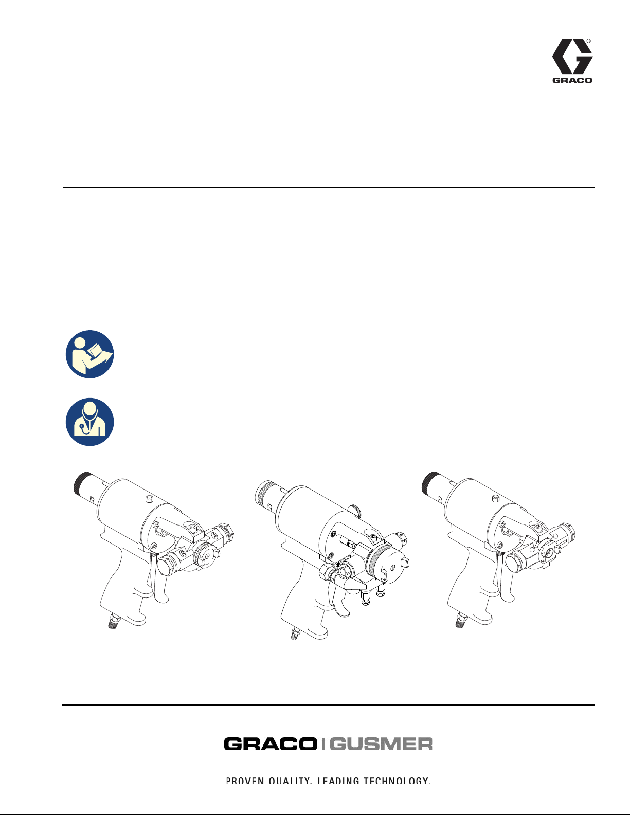
GX-7A™, GX-7® DI, and GX-7 400
Spray Guns
For the application of non-flammable polyurethane foams, two-component coating
systems (polyureas), and some two-component epoxy systems. For professional use only.
See page 3 for model information.
3500 psi (24 MPa, 240 bar) Maximum Fluid Working Pressure
125 psi (0.86 MPa, 8.6 bar) Maximum Air Working Pressure
Important Safety Instructions
Read all warnings and instructions in this
manual before using the equipment.
Save these instructions.
311321V
EN
Important Medical Information
Read the medical alert card provided with
the gun. It contains injection injury
treatment information for a doctor. Keep it
with you when operating the equipment.
GX-7A
2!
GX-7 400
GX-7A DI
Page 2

Related Manuals
Contents
Related Manuals . . . . . . . . . . . . . . . . . . . . . . . . . . . . 2
Models . . . . . . . . . . . . . . . . . . . . . . . . . . . . . . . . . . . . 3
Warnings . . . . . . . . . . . . . . . . . . . . . . . . . . . . . . . . . . 4
Important Isocyanate (ISO) Information . . . . . . . . . 6
Isocyanate Conditions . . . . . . . . . . . . . . . . . . . . . 6
Material Self-Ignition . . . . . . . . . . . . . . . . . . . . . . 7
Keep Components A and B Separate . . . . . . . . . 7
Moisture Sensitivity of Isocyanates . . . . . . . . . . . 7
Foam Resins with 245 fa Blowing Agents . . . . . . 7
Changing Materials . . . . . . . . . . . . . . . . . . . . . . . 7
Component Identification . . . . . . . . . . . . . . . . . . . . 8
Model GX-7A . . . . . . . . . . . . . . . . . . . . . . . . . . . . 8
Model GX-7 DI . . . . . . . . . . . . . . . . . . . . . . . . . . . 9
Model GX-7 400. . . . . . . . . . . . . . . . . . . . . . . . . 10
Centerline Components . . . . . . . . . . . . . . . . . . . 11
Mixing Module . . . . . . . . . . . . . . . . . . . . . . . . . . 14
Operation. . . . . . . . . . . . . . . . . . . . . . . . . . . . . . . . . 15
Grounding . . . . . . . . . . . . . . . . . . . . . . . . . . . . . 15
Air Hose Connection . . . . . . . . . . . . . . . . . . . . . 15
Safety Lock . . . . . . . . . . . . . . . . . . . . . . . . . . . . 15
Manual Valves . . . . . . . . . . . . . . . . . . . . . . . . . . 16
Coupling Block . . . . . . . . . . . . . . . . . . . . . . . . . . 16
Pressure Relief Procedure. . . . . . . . . . . . . . . . . 17
Flush Gun . . . . . . . . . . . . . . . . . . . . . . . . . . . . . 18
Initial Set Up. . . . . . . . . . . . . . . . . . . . . . . . . . . . 18
Daily Start-up . . . . . . . . . . . . . . . . . . . . . . . . . . . 19
Daily Shutdown . . . . . . . . . . . . . . . . . . . . . . . . . 20
Optional Configuration . . . . . . . . . . . . . . . . . . . . . 21
Air Inlet Configuration . . . . . . . . . . . . . . . . . . . . 21
Install Mixing Module . . . . . . . . . . . . . . . . . . . . . 21
Install PCD . . . . . . . . . . . . . . . . . . . . . . . . . . . . . 22
Check Adjustment of Valving Rod . . . . . . . . . . . 22
Adjust Valving Rod. . . . . . . . . . . . . . . . . . . . . . . 23
Maintenance . . . . . . . . . . . . . . . . . . . . . . . . . . . . . . 24
Gun Service Kits. . . . . . . . . . . . . . . . . . . . . . . . . 24
Clean Spray Gun . . . . . . . . . . . . . . . . . . . . . . . . 24
Repair. . . . . . . . . . . . . . . . . . . . . . . . . . . . . . . . . . . . 26
Service Screen Screw . . . . . . . . . . . . . . . . . . . . 26
Remove and Service Centerline Components . . 26
Install Centerline Components . . . . . . . . . . . . . . 28
Replace End Cap and Air Piston Assembly . . . . 29
Replace Trigger Valve O-Rings . . . . . . . . . . . . . 30
Clean Mixing Module . . . . . . . . . . . . . . . . . . . . . 31
Install Mixing Module . . . . . . . . . . . . . . . . . . . . . 32
Clean Pattern Control Disc . . . . . . . . . . . . . . . . . 32
Parts . . . . . . . . . . . . . . . . . . . . . . . . . . . . . . . . . . . . . 34
GX-7A Assembly . . . . . . . . . . . . . . . . . . . . . . . . 34
GX-7 DI Assembly (295541). . . . . . . . . . . . . . . . 36
GX-7 400 Assembly (295540) . . . . . . . . . . . . . . 38
GX-7A Handle (24K734). . . . . . . . . . . . . . . . . . . 40
GX-7 DI Handle (295809). . . . . . . . . . . . . . . . . . 42
GX-7 400 Handle (24K733) . . . . . . . . . . . . . . . . 44
Coupling Block Assembly (295383) . . . . . . . . . . 46
Specifications . . . . . . . . . . . . . . . . . . . . . . . . . . . . . 47
GX-7A Mix Module Kit . . . . . . . . . . . . . . . . . . . . 47
Set-Up Chart for GX-7A Model. . . . . . . . . . . . . . 48
GX-7 400 Mix Module Kit . . . . . . . . . . . . . . . . . . 49
Set-up Chart for GX-7 400 Model. . . . . . . . . . . . 50
GX-7 DI Model Specifications. . . . . . . . . . . . . . . 51
Tip Kits . . . . . . . . . . . . . . . . . . . . . . . . . . . . . . . . 52
Tool Kit . . . . . . . . . . . . . . . . . . . . . . . . . . . . . . . . 52
Technical Specifications . . . . . . . . . . . . . . . . . . . . 53
California Proposition 65 . . . . . . . . . . . . . . . . . . . . 53
Graco Standard Warranty . . . . . . . . . . . . . . . . . . . 54
Related Manuals
Manuals are available at www.graco.com
Manual in
English
311340
311341 Gusmer Directional Valve Kit
2 311321V
Description
Gusmer® Gun Service Kits
Page 3

Models
Models
Part Description
295540 GX-7 400 296859 (451) 296853 (212)
295541 GX-7 DI - 4/213 296901 (4) 296706 (213)
295542 GX-7A - 1/90 296909 (1) 296712 (90)
295543 GX-7A - 10/210 296906 (10) 296704 (210)
295544 GX-7A - 3/70 296226 (3) 296710 (70)
295545 GX-7A - 5/70 296923 (5) 296710 (70)
25E217 GX-7A - A3 Slabjacking 296876 (A3) Not included
25F046 GX-7A-A3 Slabjacking OEM 296566 (A3) Not Included
Mix Module Tip
Includes:
311321V 3
Page 4
Warnings
Warnings
The following warnings are for the setup, use, grounding, maintenance, and repair of this equipment. The
exclamation point symbol alerts you to a general warning and the hazard symbols refer to procedure-specific risks.
When these symbols appear in the body of this manual or on warning labels, refer back to these Warnings.
Product-specific hazard symbols and warnings not covered in this section may appear throughout the body of this
manual where applicable.
WARNING
TOXIC FLUID OR FUMES HAZARD
Toxic fluids or fumes can cause serious injury or death if splashed in the eyes or on skin, inhaled or
swallowed.
• Read Safety Data Sheets (SDSs) for handling instructions and to know the specific hazards of the
fluids you are using, including the effects of long-term exposure.
• When spraying, servicing equipment, or when in the work area, always keep work area
well-ventilated and always wear appropriate personal protective equipment. See Personal
Protective Equipment warnings in this manual.
• Store hazardous fluid in approved containers, and dispose of it according to applicable guidelines.
PERSONAL PROTECTIVE EQUIPMENT
Always wear appropriate personal protective equipment and cover all skin when spraying, servicing
equipment, or when in the work area. Protective equipment helps prevent serious injury, including
long-term exposure; inhalation of toxic fumes, mists or vapors; allergic reaction; burns; eye injury and
hearing loss. This protective equipment includes but is not limited to:
• A properly fitting respirator, which may include a supplied-air respirator, chemically impermeable
gloves, protective clothing and foot coverings as recommended by the fluid manufacturer and local
regulatory authority.
• Protective eyewear and hearing protection.
SKIN INJECTION HAZARD
High-pressure fluid from gun, hose leaks, or ruptured components will pierce skin. This may look like
just a cut, but it is a serious injury that can result in amputation. Get immediate surgical treatment.
• Engage safety lock when not spraying.
• Do not point gun at anyone or at any part of the body.
• Do not put your hand over the spray tip.
• Do not stop or deflect leaks with your hand, body, glove, or rag.
• Follow the Pressure Relief Procedure when you stop spraying and before cleaning, checking, or
servicing equipment.
• Tighten all fluid connections before operating the equipment.
• Check hoses and couplings daily. Replace worn or damaged parts immediately.
4 311321V
Page 5
Warnings
WARNING
FIRE AND EXPLOSION HAZARD
Flammable fumes, such as solvent and paint fumes, in work area can ignite or explode. Paint or
solvent flowing through the equipment can cause static sparking. To help prevent fire and explosion:
• Use equipment only in well-ventilated area.
• Eliminate all ignition sources; such as pilot lights, cigarettes, portable electric lamps, and plastic drop
cloths (potential static sparking).
• Ground all equipment in the work area. See Grounding instructions.
• Never spray or flush solvent at high pressure.
• Keep work area free of debris, including solvent, rags and gasoline.
• Do not plug or unplug power cords, or turn power or light switches on or off when flammable fumes
are present.
• Use only grounded hoses.
• Hold gun firmly to side of grounded pail when triggering into pail. Do not use pail liners unless they
are anti-static or conductive.
• Stop operation immediately if static sparking occurs or you feel a shock. Do not use equipment until
you identify and correct the problem.
• Keep a working fire extinguisher in the work area.
EQUIPMENT MISUSE HAZARD
Misuse can cause death or serious injury.
• Do not operate the unit when fatigued or under the influence of drugs or alcohol.
• Do not exceed the maximum working pressure or temperature rating of the lowest rated system
component. See Technical Specifications in all equipment manuals.
• Use fluids and solvents that are compatible with equipment wetted parts. See Technical
Specifications in all equipment manuals. Read fluid and solvent manufacturer’s warnings. For
complete information about your material, request Safety Data Sheets (SDSs) from distributor or
retailer.
• Turn off all equipment and follow the Pressure Relief Procedure when equipment is not in use.
• Check equipment daily. Repair or replace worn or damaged parts immediately with genuine
manufacturer’s replacement parts only.
• Do not alter or modify equipment. Alterations or modifications may void agency approvals and create
safety hazards.
• Make sure all equipment is rated and approved for the environment in which you are using it.
• Use equipment only for its intended purpose. Call your distributor for information.
• Route hoses and cables away from traffic areas, sharp edges, moving parts, and hot surfaces.
• Do not kink or over bend hoses or use hoses to pull equipment.
• Keep children and animals away from work area.
• Comply with all applicable safety regulations.
BURN HAZARD
Equipment surfaces and fluid that is heated can become very hot during operation. To avoid severe
burns:
• Do not touch hot fluid or equipment.
PRESSURIZED ALUMINUM PARTS HAZARD
Use of fluids that are incompatible with aluminum in pressurized equipment can cause serious chemical
reaction and equipment rupture. Failure to follow this warning can result in death, serious injury, or
property damage.
• Do not use 1,1,1-trichloroethane, methylene chloride, other halogenated hydrocarbon solvents or
fluids containing such solvents.
• Do not use chlorine bleach.
• Many other fluids may contain chemicals that can react with aluminum. Contact your material supplier
for compatibility.
311321V 5
Page 6
Important Isocyanate (ISO) Information
Important Isocyanate (ISO) Information
Isocyanates (ISO) are catalysts used in two component materials.
Isocyanate Conditions
Spraying or dispensing fluids that contain isocyanates creates potentially harmful mists, vapors, and atomized
particulates.
• Read and understand the fluid manufacturer’s warnings and Safety Data Sheets (SDSs) to know specific
hazards and precautions related to isocyanates.
• Use of isocyanates involves potentially hazardous procedures. Do not spray with this equipment unless you
are trained, qualified, and have read and understood the information in this manual and in the fluid
manufacturer’s application instructions and SDSs.
• Use of incorrectly maintained or mis-adjusted equipment may result in improperly cured material, which could
cause off gassing and offensive odors. Equipment must be carefully maintained and adjusted according to
instructions in the manual.
• To prevent inhalation of isocyanate mists, vapors and atomized particulates, everyone in the work area must
wear appropriate respiratory protection. Always wear a properly fitting respirator, which may include a
supplied-air respirator. Ventilate the work area according to instructions in the fluid manufacturer’s SDSs.
• Avoid all skin contact with isocyanates. Everyone in the work area must wear chemically impermeable
gloves, protective clothing and foot coverings as recommended by the fluid manufacturer and local regulatory
authority. Follow all fluid manufacturer recommendations, including those regarding handling of
contaminated clothing. After spraying, wash hands and face before eating or drinking.
• Hazard from exposure to isocyanates continues after spraying. Anyone without appropriate personal
protective equipment must stay out of the work area during application and after application for the time
period specified by the fluid manufacturer. Generally this time period is at least 24 hours.
• Warn others who may enter work area of hazard from exposure to isocyanates. Follow the recommendations
of the fluid manufacturer and local regulatory authority. Posting a placard such as the following outside the
work area is recommended:
TOXIC FUMES
HAZARD
DO NOT ENTER DURING
SPRAY FOAM APPLICATION
OR FOR ___ HOURS AFTER
APPLICATION IS COMPLETE
DO NOT ENTER UNTIL:
DATE:
TIME:
6 311321V
____________
____________
Page 7
Important Isocyanate (ISO) Information
Material Self-Ignition
Some materials may become self-igniting if applied
too thick. Read material manufacturer’s warnings and
Safety Data Sheets (SDSs).
Keep Components A and B Separate
Cross-contamination can result in cured material in
fluid lines which could cause serious injury or damage
equipment. To prevent cross-contamination:
• Never interchange component A and component
B wetted parts.
• Never use solvent on one side if it has been
contaminated from the other side.
NOTICE
Partially cured ISO will reduce performance and the life
of all wetted parts.
• Always use a sealed container with a desiccant
dryer in the vent, or a nitrogen atmosphere. Never
store ISO in an open container.
• Keep the ISO pump wet cup or reservoir (if
installed) filled with appropriate lubricant. The
lubricant creates a barrier between the ISO and the
atmosphere.
• Use only moisture-proof hoses compatible with
ISO.
• Never use reclaimed solvents, which may contain
moisture. Always keep solvent containers closed
when not in use.
• Always lubricate threaded parts with an appropriate
lubricant when reassembling.
NOTE: The amount of film formation and rate of
crystallization varies depending on the blend of ISO, the
humidity, and the temperature.
Moisture Sensitivity of Isocyanates
Exposure to moisture (such as humidity) will cause ISO
to partially cure, forming small, hard, abrasive crystal
that become suspended in the fluid. Eventually a film will
form on the surface and the ISO will begin to gel,
increasing in viscosity.
Foam Resins with 245 fa Blowing Agents
Some foam blowing agents will froth at temperatures
above 90°F (33°C) when not under pressure, especially
if agitated. To reduce frothing, minimize preheating in a
circulation system.
Changing Materials
NOTICE
Changing the material types used in your equipment
requires special attention to avoid equipment damage
and downtime.
• When changing materials, flush the equipment
multiple times to ensure it is thoroughly clean.
• Always clean the fluid inlet strainers after flushing.
• Check with your material manufacturer for
chemical compatibility.
• When changing between epoxies and urethanes or
polyureas, disassemble and clean all fluid
components and change hoses. Epoxies often
have amines on the B (hardener) side. Polyureas
often have amines on the B (resin) side.
311321V 7
Page 8
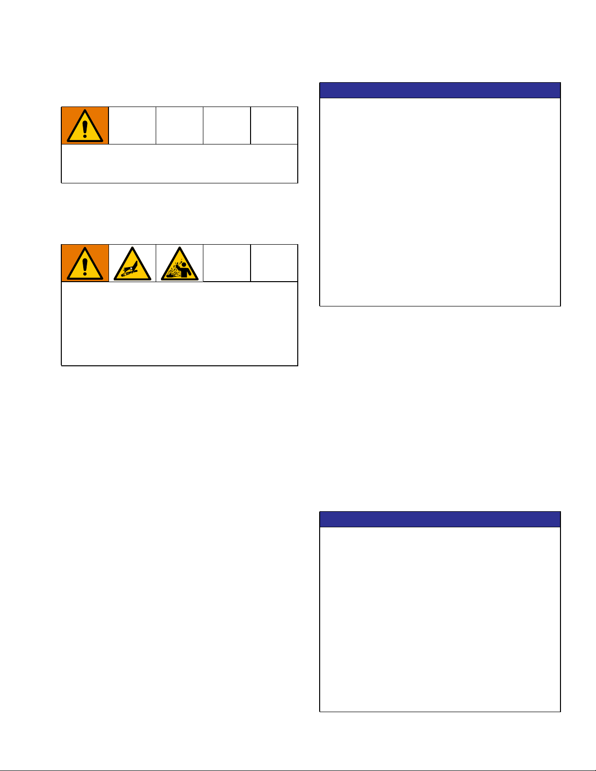
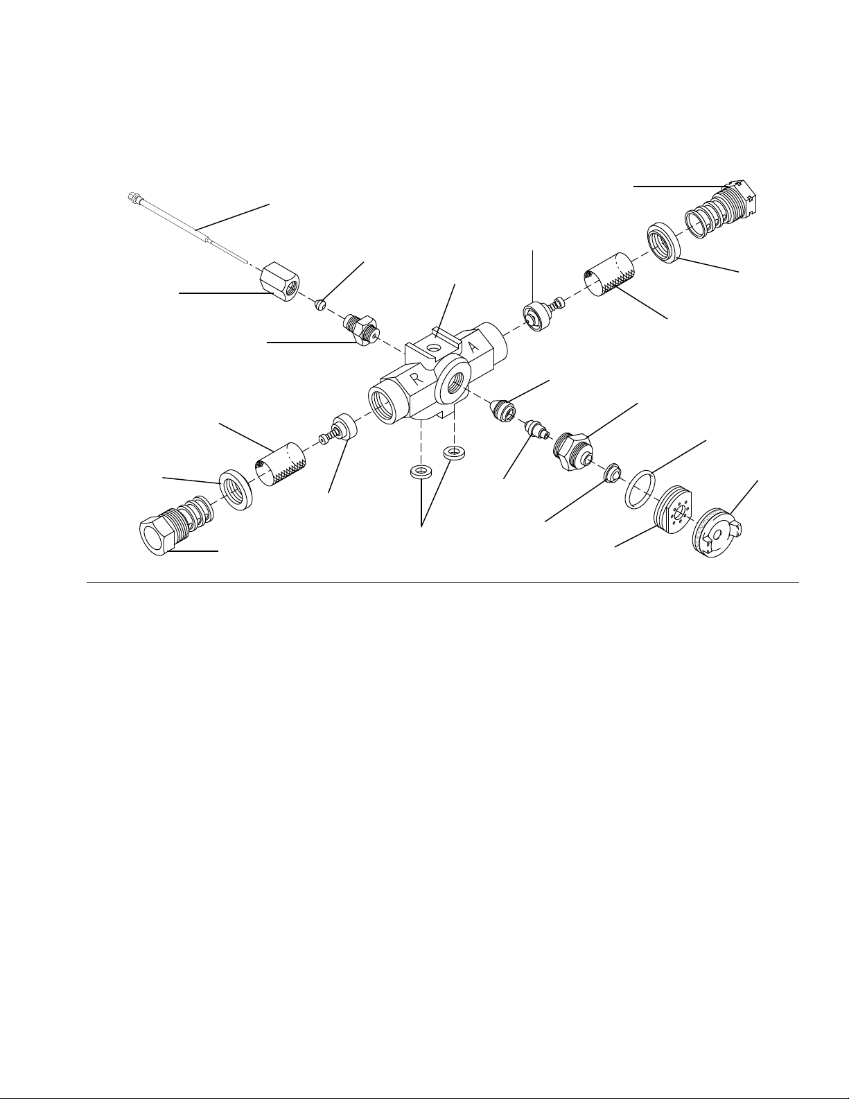
Component Identification
2 !
Component Identification
Model GX-7A
A
B
H
G
F
E
FIG. 1
Key
A Forward Stop Locknut
B Gun Block
C Manual Valve
D Trigger
C
D
Key
E Rear Packing Nut
F Valving Rod Forward Stop
G Air Cap Adjustment Valve
H Safety Lock
8 311321V
Page 9
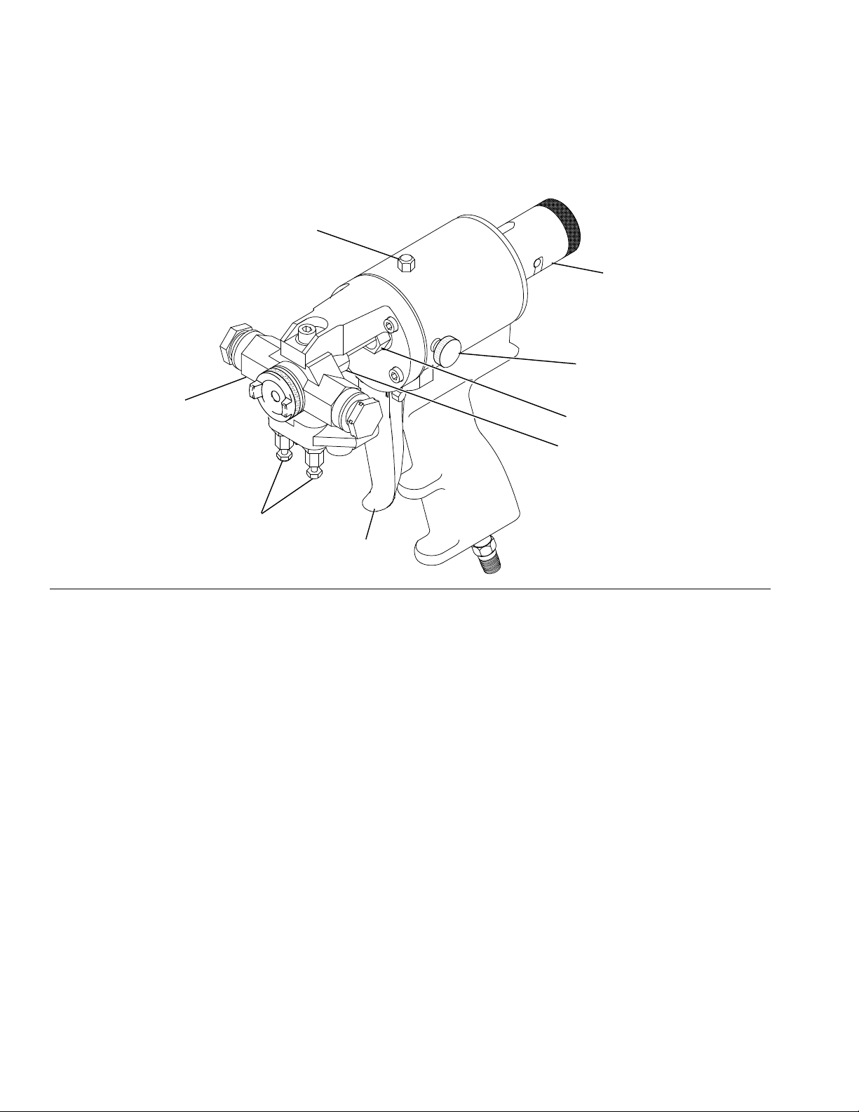
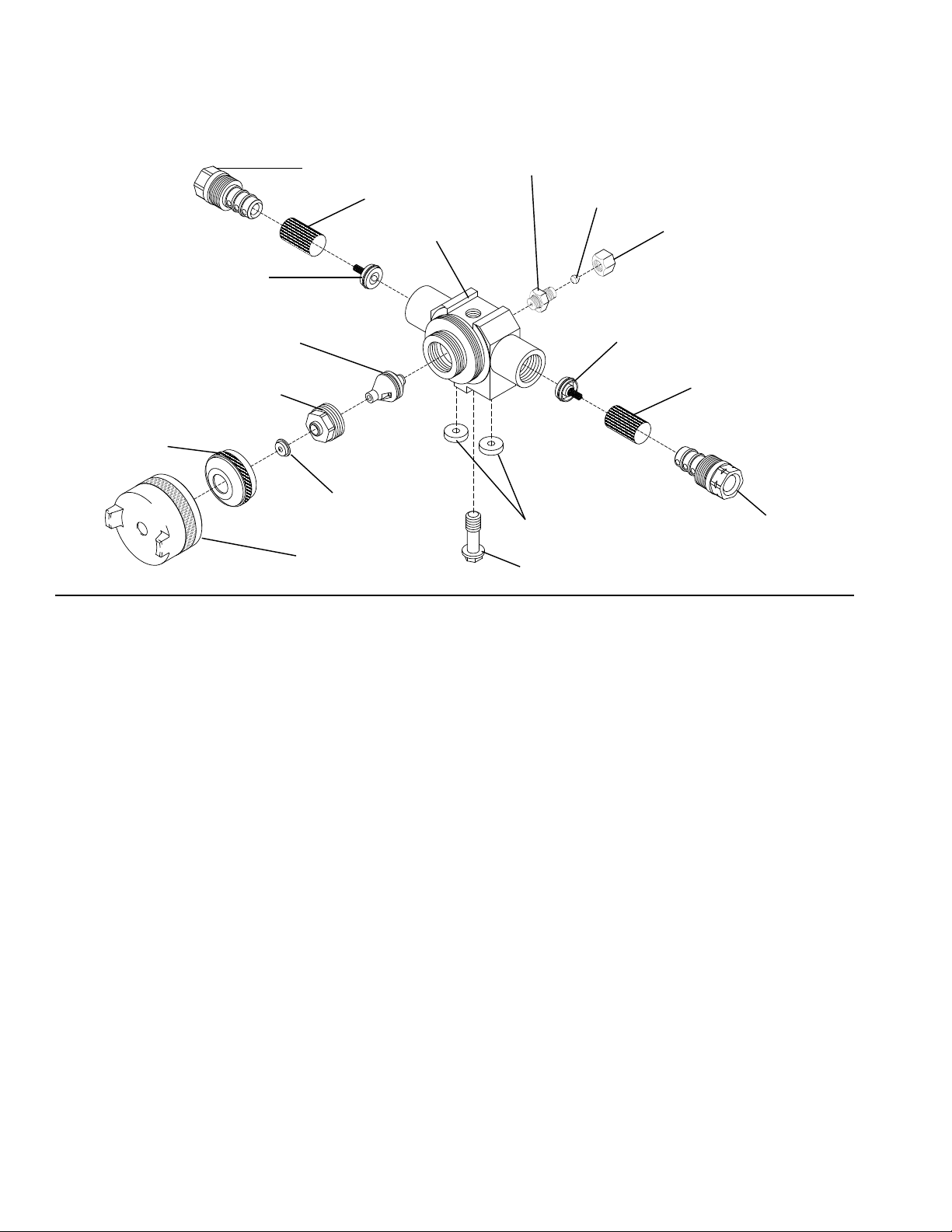
Model GX-7 DI
Component Identification
H
B
M
FIG. 2
Key
B Gun Block
C Manual Valve
D Trigger
G Air Cap Adjustment Valve
H Safety Lock
G
K
P
N
C
J
D
Key
J Coupling Block
K Piston Rod
M Air Cap
N Valving Rod
P Lock Nut
311321V 9
Page 10
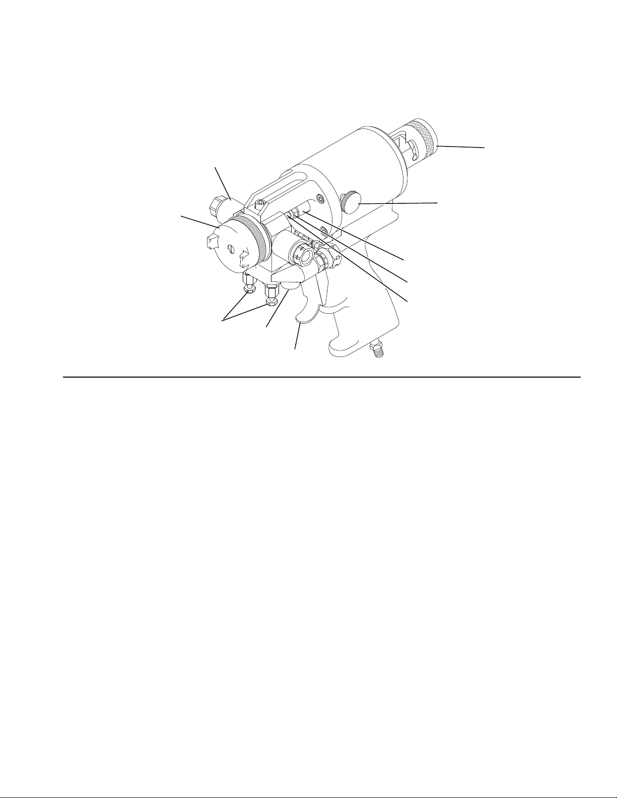
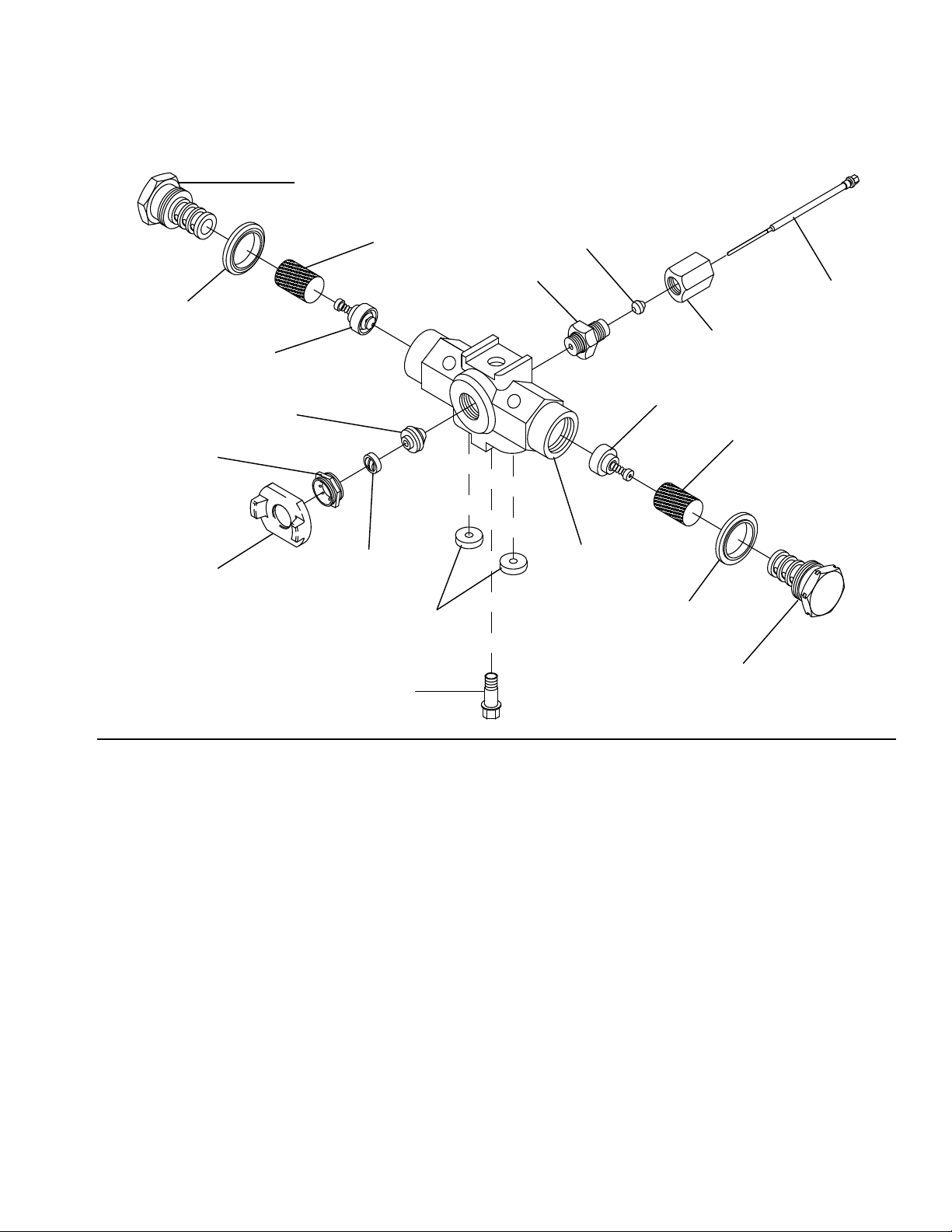
Component Identification
Model GX-7 400
A
H
2
!
B
FIG. 3
Key
A Forward Stop Locknut
B Gun Block
D Trigger
E Rear Packing Nut
G
F
D
E
Key
F Valving Rod Forward Stop
G Air Cap Adjustment Valve
H Safety Lock
10 311321V
Page 11
Centerline Components
Model GX-7A
Component Identification
FIG. 4
W
N
S
B
T
U
V
Z
ZAA
Y
Z
ZAH
ZAB
ZAC
ZAJ
W
V
ZAE
ZAG
M
ZAD
Key
B Gun Block
N Valving Rod
M Air Cap
S Rear Packing
T Rear Seal Retainer
U Rear Packing Retainer
V Screen
W Screen Screw Seal
Y R-Screen Screw
Key
Z Check Valve
ZAA Coupling Block Gasket
ZAB Front Packing
ZAC Pattern Control Disc (PCD)
ZAD PCD Retainer
ZAE PCD Body
ZAG O-ring
ZAH Mixing Module
ZAJ A-Screen Screw
311321V 11
Page 12
Component Identification
Model GX-7 DI
FIG. 5
ZAD
Z
ZAM
ZAH
M
Y
ZAC
ZAN
V
B
ZAA
ZAR
S
ZAP
Z
V
ZAJ
Key
B Gun Block
M Air Cap
S Rear Packing
V Screen
Z Check Valve
ZAA Coupling Block Gasket
ZAC Pattern Control Disc (PCD)
Key
ZAD PCD Retainer
ZAJ A-Screen Screw
ZAH Mixing Module
ZAM Mixing Module Retainer
ZAN Rear Seal Gland
ZAP Rear Seal Retainer Assembly
ZAR Coupling Block Mounting Screw
12 311321V
Page 13
Model GX-7 400
Component Identification
Y
W
ZAD
ZAF
Z
ZAH
ZAC
ZAS
ZAR
ZAA
S
T
N
U
Z
V
B
W
ZAJ
FIG. 6
Key
B Gun Block
M Air Cap
N Valving Rod
S Rear Packing
T Rear Seal Retainer
U Rear Packing Retainer
V Screen
W Screen Screw Seal
Y R-Screen Screw
Key
Z Check Valve
ZAA Coupling Block Gasket
ZAC Pattern Control Disc (PCD)
ZAD PCD Retainer
ZAH Mixing Module
ZAJ A-Screen Screw
ZAR Coupling Block Mounting Screw
ZAS Spring
311321V 13
Page 14
Component Identification
Mixing Module
All gun models employ the concept of impingement
mixing through the use of a single-part MIXING
MODULE. This system is cleaned by a mechanical
self-cleaning process, eliminating the need for solvent or
air purging between dispenses.
The gun can be assembled with either a round or flat
mixing module, depending on the type of system used to
spray. The Set-Up Charts on pages 48 and 50 show
several of the more common sets of these
configurations.
The Mixing Module, in combination with a Pattern
Control Disc (PCD) (ZAC), produce a thoroughly mixed
chemical and reliable spray patterns. The module can
be set up to spray at its maximum rated output.
Additionally, by changing to a smaller PCD the module
can spray at the low outputs and pressures that are
required for detail work.
GX-7A
ZAC (round or flat)
N
ZAH
(round or flat)
GX-7A 400
N
ZAH (round or flat)
ZAC (round or flat)
ZAH (round or flat)
ZAC (round or flat)
FIG. 7 Mixing Modules
GX-7 DI
N
14 311321V
Page 15
Operation
To prevent accidental gun operation, always
disconnect air supply before servicing gun or anytime
gun is not in use.
Grounding
The equipment must be grounded to reduce the risk
of static sparking. Static sparking can cause fumes to
ignite or explode. Grounding provides an escape wire
for the electric current.
Follow local codes, regulations, and your proportioner
manual for detailed grounding instructions.
Operation
Safety Lock
High-pressure fluid from dispensing devices can
pierce skin. To help prevent serious injury from
pressurized fluid, always engage the piston safety
lock and close the material shutoff valves to avoid
accidental triggering whenever you stop spraying.
The CLOSED (SERVICE) position will not allow the gun
to discharge. The OPEN position allows the gun to
dispense. Whenever the gun is not spraying, set to
CLOSED (SERVICE) position.
To engage safety lock: push in and turn the safety lock
clockwise to place the gun in CLOSED (SERVICE)
position.
Spray gun: ground the spray gun through connection to
a properly grounded fluid hose and pump.
Air Hose Connection
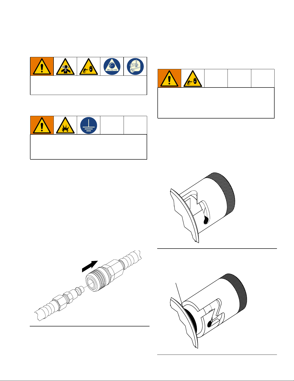
To connect air hoses: pull back the sleeve of the
female fitting, insert the male fitting and slide the sleeve
forward to secure connection.
To disconnect air hoses: pull back the sleeve of the
female fitting and pull out the male fitting.
Pull Sleeve
CLOSED (SERVICE)
Put in safety position when not
spraying.
FIG. 9: Safety Lock - Closed
To disengage safety lock: push in and turn the safety
lock counterclockwise to place the gun in OPEN position
(red band is exposed).
Red Band
FIG. 8
FIG. 10: Safety Lock - Open
311321V 15
OPEN
Red band exposed to
spray.
Page 16
Operation
Manual Valves
NOTE: Triggering the gun with the manual valves (C)
closed may cause crossover if the gun ports contain
residual chemical.
Closing the manual valves (C) prevents chemicals in
heated hoses from entering the gun. Close the manual
valves before servicing gun.
Never open manual valves (C) unless coupling block
(J) is secured to gun or exit port is directed into flush
pail.
To open the manual valves (C): Use a 5/16 in. nut
driver to turn the manual valve counterclockwise three
full turns. Do not open until it bottoms out.
To close the manual valves (C): turn the manual
valves clockwise until tight.
Coupling Block
Chemical hoses are joined to the gun block (B) by the
coupling block (J) to ease installation and removal of the
gun.
B
H
ZAA
J
C
FIG. 12 Coupling Block
Install Coupling Block
1. Inspect the coupling block (J) gaskets for damage
and wear. Replace if necessary.
ZAR
J
C
FIG. 11 Manual Valves
2. With gaskets in place, fit the coupling block (J) to
the gun block (B).
3. Insert the coupling block (J) mounting screw and
tighten securely with a 5/16 in. nut driver.
Remove Coupling Block
To prevent release of pressurized chemical, close
both manual valves (C) before removing coupling
block (J).
1. Set the safety lock (H) to CLOSED (SERVICE).
2. Disconnect the air hose.
3. Close both manual valves (C).
4. Remove the coupling block (J) mounting screw.
5. Separate the coupling block (J) from the gun.
6. Wipe the mating surfaces of the gun block (B) and
coupling block (J) to remove residual chemical.
7. Cover exposed openings with grease.
16 311321V
Page 17
Operation
Pressure Relief Procedure
Follow the Pressure Relief Procedure whenever
you see this symbol.
This equipment stays pressurized until pressure is
manually relieved. To help prevent serious injury from
pressurized fluid, such as skin injection or splashing
fluid, follow the Pressure Relief Procedure when you
stop spraying and before cleaning, checking, or
servicing the equipment.
1. Close both manual valves (C).
C
ti39022a
4. Set the safety lock (H) to CLOSED (SERVICE).
H
CLOSED (SERVICE)
ti39025a
5. Disconnect the gun air supply.
ti39026a
NOTE: If the gun is removed from the coupling block (J),
follow Clean Spray Gun, page 24.
NOTE: After the pressure in the spray gun is relieved,
the fluid in the hose and proportioner remains under
pressure. Follow the Pressure Relief Procedure in
your proportioner manual to relieve pressure in the
system.
2. Set the safety lock (H) to OPEN.
Red Band
ti39023a
H
OPEN
Red band exposed to
spray.
3. Trigger the gun once onto waste area to relieve fluid
pressure in front end of the gun.
ti39024a
311321V 17
Page 18

Operation
Flush Gun
To avoid fire and explosion, always ground equipment
and waste container. To avoid static sparking and
injury from splashing, always flush at the lowest
possible pressure.
1. Set the safety lock (H) to CLOSED (SERVICE).
H
CLOSED (SERVICE)
ti39025a
2. Close both manual valves (C).
Initial Set Up
1. Remove the coupling block (J) from the gun. Follow
Remove Coupling Block, page 16.
2. Install the female quick disconnect fitting to the air
supply hose bundled with the chemical supply
hoses.
3. Connect A-isocyanate hose (red-taped) to the
notched fitting on coupling block (J). Then connect
B-resin hose (blue-taped) to the fitting without
notches on coupling block.
4. Close both manual valves (C).
C
C
ti39022a
3. Loosen the R-screen screw (Y) and then remove by
hand.
4. Use a flush can to thoroughly flush the screen screw
and screen screw cavity.
5. Loosen the A-Screen screw (ZAJ) and then remove
by hand.
6. Use a flush can to thoroughly flush the screen screw
and screen screw cavity.
7. Service the gun by following Maintenance
procedures, page 24.
ti39022a
5. Pressurize the A and B chemical hoses and check
for leaks. (Refer to your proportioning system
manual.)
6. Bleed air from chemical hoses.
a. Use separate waste containers for A-ISO and
B-Resin.
b. Hold the coupling block (J) with exit ports
pointed into waste container.
c. Open the manual valves (C) one at a time to
dispense into waste container.
d. Bleed each side until chemical leaving hoses is
free of air.
e. Close both manual valves (C).
18 311321V
Page 19

Operation
7. Use a clean cloth soaked in gun cleaner to wipe
clean the coupling block (J) and mating surfaces.
NOTE: To avoid accumulation of dirt and other
contaminants, do not apply grease to mating surfaces of
the coupling block (J).
8. Set the safety lock (H) to CLOSED (SERVICE).
H
CLOSED (SERVICE)
ti39025a
9. Install the coupling block (J) to the gun. Follow
Install Coupling Block, page 16.
10. Proceed with Daily Start-up and Daily Shutdown
procedures on page 19.
Daily Start-up
Ensure the gun is attached to the coupling block (J)
and air hose, and the proportioning unit is at desired
temperature and pressure.
1. Connect the air supply to gun.
2. Adjust the air cap (M) adjustment valve (G). Turn
the knob counterclockwise to open valve and
clockwise to close valve
3. Adjust the rear seal retainer (T).
4. Close both manual valves (C).
C
ti39022a
5. Set the safety lock (H) to OPEN.
Red Band
ti39023a
H
OPEN
Red band exposed to
spray.
6. Test spray on a disposable surface and adjust the
spray pattern as needed.
311321V 19
Page 20

Operation
Daily Shutdown
NOTE: Follow when gun is out of service for any length
of time. Daily disassembly of gun for cleaning is not
recommended if it has been operating properly.
However, if you remove the gun from the coupling block
(J), flush and clean thoroughly.
1. Perform the Pressure Relief Procedure, page 17.
2. Set the safety lock (H) to OPEN.
Red Band
H
3. Disconnect the air supply from the gun.
4. Shutdown the proportioning unit as required. See
your Proportioner manual, Related Manuals, page
2.
5. Clean the gun required. See Clean Spray Gun,
page 24.
NOTE: Do not disassemble the gun daily for cleaning if
it is operating properly. However, if the gun is removed
from the coupling block (J), it must be flushed and
cleaned thoroughly.
ti39023a
OPEN
Red band exposed to
spray.
20 311321V
Page 21

Optional Configuration
Optional Configuration
Install Mixing Module
1. Perform the Pressure Relief Procedure, page 17.
Refer to Coupling Block Assembly (295383), page 46.
If bottom-mount hose connection is desired, alternate
the swivel fitting (2 and 3) with pipe plugs (1). Use pipe
thread sealant. Do not cross-over which side each fitting
is on.
Air Inlet Configuration
There are two configurations for the air inlet. In the
standard configuration the air inlet is at the base of the
handle, and in the alternate configuration the air inlet is
at the rear of the gun.
PP
PN (Optional)
PN
2. Disconnect the gun from the coupling block (J).
Follow Remove Coupling Block, page 16.
3. Connect the air supply to the gun.
4. Set the safety lock (H) to OPEN.
Red Band
ti39023a
5. Pull the trigger (D) and place the module over the tip
of valving rod (N). See , page 13.
6. GX-7 DI model only: Align keying pin with hole in
gun block (B) and push in firmly.
7. GX-7A model only: Install front packing (ZAB) into
module retainer.
H
OPEN
Red band exposed to
spray.
8. GX-7A model only: Install PCD body (ZAE) and
FIG. 13 Air Inlet Configurations
To change to alternate configuration:
1. Perform the Pressure Relief Procedure, page 17.
2. Remove the pipe nipple (PN).
3. Remove the pipe plug (PP) from rear of the gun.
4. Install the pipe plug (PP) in location previously
occupied by the pipe nipple (PN).
5. Install the pipe nipple (PN) in location previously
occupied by the pipe plug (PP).
311321V 21
hand tighten. Release trigger (D).
9. GX-7 DI model only: Install module retainer and
hand tighten. Release trigger (D).
10. GX-7A model only: Use wrench to strongly tighten
PCD body (ZAE) (250 in.-lbs.).
11. GX-7 DI model only: use wrench to tighten module
retainer (150 in.-lbs.). DO NOT OVERTIGHTEN.
Page 22

Optional Configuration
Install PCD
1. Perform the Pressure Relief Procedure, page 17.
2. Disconnect the air supply from the gun.
3. GX-7 model only: Loosen the forward stop screw.
4. GX-7 model only: Turn the forward stop nut (A)
clockwise (as viewed from front of gun) 1-2 turns.
Make sure the valve rod is exposed.
5. Slightly loosen the rear seal retainer assembly
(ZAP).
6. Remove the safety lock (H).
7. GX-7 DI model only: Use wrench to loosen the
piston locknut. Turn the valving rod (N) rearward as
far as it will turn.
8. Place and orient the PCD (ZAC) over the mixing
module retainer (ZAM) or the PCD body (ZAE).
9. Connect the gun to air pressure. Adjust the valve
rod (GX-7 DI) or cylinder front stop (GX-7) until the
tip of the rod is just touching the PCD (ZAC). The
PCD should be seated flat on the mixing module
(ZAH) or PCD body (ZAE).
Check Adjustment of Valving Rod
1. With the air supply connected, pull the gun trigger
(D) and loosen the PCD retainer (ZAD). Release the
trigger.
2. Hand tighten the PCD retainer (ZAD).
3. While maintaining tightening torque, trigger the gun.
The retainer should rotate approximately 1/10 of
turn.
4. Release the trigger (D).
10. GX-7 DI model only: Install PCD retainer (ZAD)
and hand tighten.
11. GX-7 model only: Install PCD retainer (ZAD) and
wrench tighten.
12. Adjust the valving rod (N). Follow Adjust Valving
Rod, page 23, for the appropriate gun model.
13. Set the safety lock (H) to OPEN.
Red Band
ti39023a
H
OPEN
Red band exposed to
spray.
22 311321V
Page 23

Optional Configuration
Adjust Valving Rod
GX-7A and GX-7 400 Models Only
1. Perform the Pressure Relief Procedure, page 17.
2. Set the safety lock (H) to CLOSED (SERVICE).
H
CLOSED (SERVICE)
ti39025a
3. If attached, turn both manual valves (C) fully
clockwise to close
A
8. Loosen the forward stop locknut (A) with
approximately 1/6 of a counterclockwise turn.
NOTE: As a reference point, movement of one wrench
flat corresponds to 1/6 turn.
FIG. 15 1/6 Turn of Flat Wrench
9. Tighten the forward stop locknut (A). Do not
overtighten. If locknut bottoms out before resistance
is felt, replace friction plug.
GX-7 DI Model Only
The valving rod (N) requires adjustment in only the
following instances:
- disassembly and service of the air cylinder
- changing the valving rod (N)
- changing the mixing module (ZAH)
C
FIG. 14 Adjust the Valving Rod
4. Connect the air line from the gun to the air source to
pressurize the air cylinder forward to the CLOSED
position.
5. Loosen the forward stop locknut (A).
6. Completely loosen the forward stop locknut (A) by
turning fully counterclockwise.
7. Slowly tighten the forward stop locknut (A) by
turning clockwise until a snug resistance is felt.
1. Clean the gun according to Clean Spray Gun, page
24.
2. Connect the air supply to the gun.
3. Loosen the rear seal retainer assembly (ZAP) one
or two turns.
4. Loosen the locknut from the valving rod (N) three or
four turns.
5. Set the safety lock (H) to OPEN.
6. Use a 5/16 in. nut driver through rear of the gun to
thread the valving rod (N) forward to engage the
PCD (ZAC). When the valving rod contacts the
PCD, tighten another 1/10 turn.
7. Carefully maintain position of the valving rod (N)
and tighten the locknut against the piston rod (K).
8. Retighten the rear seal retainer assembly (ZAP).
311321V 23
Page 24

Maintenance
Maintenance
Use supplied tool kit 296835. See Tool Kit, page 52.
Gun Service Kits
Use either the 1-Quart Gun Service Kit (296980) or
3-Gallon Gun Service Kit (296981) to perform daily
flushing of spray gun without disassembly.
FIG. 16: 1-Quart Gun Service Kit
Refer to 1-Quart Gun Service Kit instructions in your
Gusmer Gun Service Kits manual. See Related
Manuals, page 2.
Clean Spray Gun
Chemicals used while spraying may cause the gun
surface to become hot to touch. Thoroughly flush the
gun block (B) with gun cleaner before removing the
valving rod (N) or mixing components from the gun
block. Also allow chemicals in the spray gun to cool
before cleaning.
Thoroughly flush the gun block (B) with gun cleaner
before removing the valving rod (N) or mixing
components from the gun block. Also allow chemicals in
the spray gun to cool before cleaning.
This procedure makes use of the 1-Quart or 3-Gallon
Gun Service Kit.
1. Perform the Pressure Relief Procedure, page 17.
2. Set the safety lock (H) to CLOSED (SERVICE).
H
CLOSED (SERVICE)
ti39025a
3. Close both manual valves (C).
FIG. 17: 3-Gallon Gun Service Kit
Refer to 3-Gallon Gun Service Kit instructions in your
Gusmer Directional Valve Kit manual. See Related
Manuals, page 2.
24 311321V
C
ti39022a
Page 25

Maintenance
4. Remove the gun from the coupling block (J). Follow
Remove Coupling Block, page 16.
5. Attach the service block of the gun service kit to the
spray gun, and then tighten using a 5/16 in. nut
driver.
6. Pressurize Service Kit container up to 100 psi.
DO NOT EXCEED 100 psi (0.7 MPa, 7 bar).
7. Open one manual valve (C) on service block.
8. Connect air to the gun.
9. Set the safety lock (H) to OPEN.
Red Band
ti39023a
H
OPEN
Red band exposed to
spray.
10. Hold the gun against a grounded waste container.
11. Trigger the gun while holding against a grounded
waste container until there is a fine, unobstructed
mist of gun cleaner.
12. Release the trigger (D) of the gun and 1-quart kit,
and close manual valves (C) on the service block.
13. Repeat steps 5-7 for other side of the gun.
14. After initial cleaning, remove the air cap (M), PCD
retainer (ZAD), and PCD (ZAC). Flush a second
time to ensure thorough cleaning.
15. Remove the service block of the gun service kit from
the spray gun.
16. Set the safety lock (H) to CLOSED (SERVICE).
17. Disconnect the air supply.
18. Clean screens (V), check valves (Z) and screen
screw (Y, ZAJ) as required. See Service Screen
Screw, page 26.
NOTE: Inspect the air cap (M), mixing chamber, and
gun block (B) for build up of material and clean as
required. Do not use metal cleaning devices to clean
plastic components.
311321V 25
Page 26

Repair
Repair
Remove and Service Centerline Components
Refer to Centerline Components, page 11, for
diagrams of centerline components for all gun models.
Shut down the proportioner and allow chemicals to
cool before performing any repair procedures.
NOTE: Clean A and B components in separate
containers to avoid cross contamination.
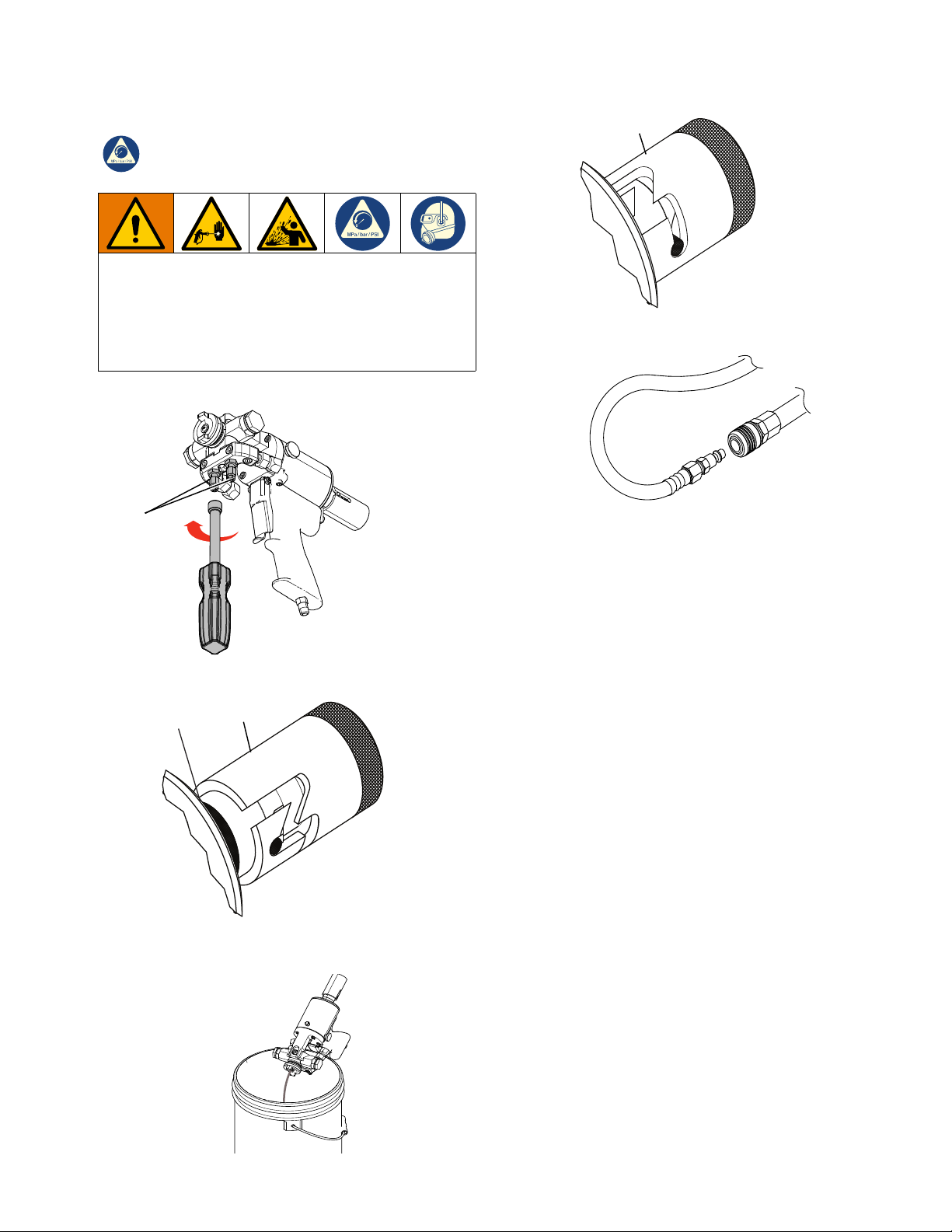
Service Screen Screw
1. Flush the gun according to Flush Gun, page 18.
2. Unthread the screen screw (Y, ZAJ) from the gun
block (B).
3. Remove the check valve (Z) from the screen screw
(Y, ZAJ). Clean the valve with gun cleaner and
inspect for damage. Replace if necessary.
4. Remove the screen (V) from the screen screw
(Y, ZAJ). Soak in gun cleaner or replace if clogged
or dirty.
5. Clean the screen screw cavity. If any particles are
visible, clean with clean out drills and flush with gun
cleaner.
NOTICE
Any material left in the cavity on downstream side of
screen (V) will clog the mixing module (ZAH).
6. Inspect the screen screw seal (W) for damage.
Replace if necessary.
1. Flush the gun according to Flush Gun, page 18.
2. Connect the air supply to the gun.
3. Set the safety stop (H) to OPEN.
Red Band
ti39023a
4. Remove the air cap (M).
5. Trigger the gun and hold it to relieve pressure on the
PCD retainer (ZAD).
6. Remove the PCD retainer (ZAD) by turning it
counterclockwise.
7. Remove the PCD (ZAC) from the mixing module
retainer (ZAM).
NOTE: To remove the PCD (ZAC) that is stuck, set the
safety lock (H) to OPEN, depress and release the gun
trigger (D) to unseat it. Set the safety lock to CLOSED
(SERVICE).
H
OPEN
Red band exposed to
spray.
7. Reinstall the screen screw (Y, ZAJ) in gun block (B).
Make sure it is tight.
8. Flush the gun with the mixing module (ZAH)
removed.
8. Remove the mixing module retainer (ZAM).
26 311321V
H
CLOSED (SERVICE)
ti39025a
Page 27

Repair
9. Set the safety lock (H) to OPEN. Depress and
release the gun trigger (D) to unseat it. Remove the
mixing module (ZAH) off end of the valving rod (N).
Set the safety lock to CLOSED (SERVICE).
NOTICE
Do not use sharp objects or metal tools to remove
mixing module (ZAH).
10. Loosen the rear packing nut (E) 1-2 turns.
11. Push the safety lock (H) partially forward, rotate it
counterclockwise, and slide off the air cylinder.
12. Remove the valving rod (N).
a. Depress the trigger (D) lever and hold.
b. GX-7 DI model only: loosen the piston stop
locknut until it disengages from thread on the
valving rod (N).
c. Use a 5/16 in. nut driver to unthread the valving
rod (N) from the rear of gun.
d. When threads disengage remove assembly by
hand.
13. Inspect the valving rod (N) for damage and replace
as required. Clean and remove any buildup of mixed
material from the rod using cloth soaked in gun
cleaner or fine steel wool.
NOTE: If the valving rod (N) is replaced, it is
recommended to reset the forward stop. See Adjust
Valving Rod, page 23.
14. Disconnect the air supply.
15. Remove the gun block (B) retaining screw. Carefully
slide the gun block away from the air cylinder. If
dried chemical is built up on the gun block, remove
dried chemical before you remove the gun block.
16. Clean all components thoroughly. Use brushes and
clean-out tools to remove residual chemical from
metal components. Use cotton swabs soaked in gun
cleaner to clean plastic components.
17. Coat threads and mating surfaces of the gun block
(B) and the gun block bracket with Lubriplate
grease, and reassemble.
18. Insect the gun block (B) for damage.
DB
N
FIG. 18 Remove Valving Rod (GX-7 DI model)
N
H
H
FIG. 19 Remove Valving Rod (GX-7A and GX-7 400
models)
311321V 27
Page 28

Repair
Install Centerline Components
GX-7 DI Model Only
Before installation, ensure all gun components are clean
and dry. Lubricate all moving parts and threads.
1. Install the rear packing gland with a packing wrench.
Tighten onto the gun block (B).
2. Install the rear packing retainer (U) loosely.
3. Install the valving rod (N). Use a 5/16 in. nut driver
to thread assembly tight into the end cap.
4. GX-7 DI model only: thread rod until approximately
3/16 in. to 1/4 in.of thread protrudes from end of the
piston rod (K).
5. Thread the locknut onto the valving rod (N) by hand.
6. Carefully slide the gun block (B) onto the valving rod
(N) toward the air cylinder. Install the gun block onto
the gun block mounting bracket.
7. Install the safety lock (H); leave in the OPEN
position.
b
Red Band
H
10. GX-7 DI model only: ensure the valving rod (N)
alignment pin enters the alignment slot in the gun
block (B). Keep the gun trigger (D) depressed.
11. With the gun trigger (D) depressed, thread mixing
module retainer (ZAM) or PCD body (ZAE) with
packing installed, by hand, and then wrench tighten.
NOTICE
To avoid damage to module and gun block (B), do
not over-tighten mixing module retainer (ZAM).
12. Release the gun trigger (D).
13. Install the PCD (ZAC) over end of the mixing
module retainer (ZAM).
14. Thread the PCD retainer (ZAD) onto the gun block
(B). Hand tight.
15. Rotate flat PCD (ZAC) to adjust orientation as
required.
16. Adjust the valving rod (N). See Adjust Valving
Rod, page 23.
17. Thread the air cap (M) into place; hand tight.
18. Slide the safety lock (H) onto rear of the air cylinder.
Push the safety lock partially forward and rotate
clockwise to set to OPEN.
OPEN
Red band exposed to
spray.
ti39023a
8. Connect the air supply to gun.
9. Depress the gun trigger (D) and slide the mixing
module (ZAH) over end of the valving rod (N).
19. Set the safety lock (H) to CLOSED (SERVICE).
H
CLOSED (SERVICE)
ti39025a
28 311321V
Page 29

Repair
Replace End Cap and Air Piston Assembly
1. Clean the gun according to Clean Spray Gun, page
24.
2. Loosen the rear packing nut (E) 1-2 turns.
3. Push the safety lock (H) partially forward, rotate
counterclockwise, and slide the safety lock (H) off
the air cylinder.
4. Remove the valving rod (N). See Remove and
Service Centerline Components, page 26.
5. Disconnect the air supply from the gun.
6. Remove the rear head cap screw (SH) and cylinder
clamp (CC) from the handle.
EC
SP
PA
RS
FS
PS
9. Inspect the rear U-cup seal (RS) or o-ring for
damage. Replace if necessary. If removed, ensure
“cup” faces front of the air cylinder when replacing.
10. By hand, pull the piston assembly (PA) out of the air
cylinder and inspect the o-ring for damage. Replace
if necessary. Apply Lubriplate grease prior to
installation.
11. If air was escaping around piston rod (K) during
operation, replace the front u-cup seal (FS) or
o-ring. Apply Lubriplate grease and ensure “cup”
faces rear of the air cylinder.
12. Insert the piston and rod assembly (PA) into the air
cylinder. Take care to not damage the front cup seal
as rod passes through.
13. Insert the piston spring (PS). (For GX-7 DI models,
also insert a piston spacer.)
14. Reinstall the end cap (EC) into the air cylinder.
15. Retighten the rear socket head cap screw (SH) and
cylinder clamp (CC) to handle.
16. Reinstall the valving rod (N). Connect the valving
rod (N) to the draw bar (DB), see FIG. 19, page 27.
Lubricate and thread into the end cap (EC).
SH
CC
GX-7 DI Shown
FIG. 20 GX-7 DI End Cap and Air Piston Assembly
7. Remove the end cap (EC) from the air cylinder.
8. Inspect the end cap (EC) o-ring. Replace if
damaged. Install a new end cap o-ring after lightly
coating it with Lubriplate grease.
17. Adjust the valving rod (N); see Adjust Valving Rod,
page 23.
18. Slide the safety lock (H) onto the rear of the air
cylinder. Push the safety lock partially forward and
rotate clockwise to set to OPEN.
19. Set the safety lock (H) to CLOSED (SERVICE).
20. Tighten the rear packing nut (E).
311321V 29
Page 30

Repair
Replace Trigger Valve O-Rings
1. Clean the gun according to Clean Spray Gun, page
24.
2. Disconnect the air supply from the gun.
3. Remove the mounting screw (TS) and locknut (TN)
that hold the trigger (D) in place. Remove the
trigger.
PP
SS
VL
VS
VP
VN
FIG. 21 Replace Trigger Valve O-Ring
4. Remove the valve retainer nut (VN).
5. Pull out the valve spool (VS) and valve spring (VP).
Remove the old o-rings.
TN
TS
IP
PN
NOTE: For guns configured with an air inlet at rear of
the gun handle, the pipe nipple replaces the pipe plug.
Remove the pipe nipple.
8. Remove the rear internal pipe plug (IP, under the
pipe plug).
9. Use a pin punch and hammer to gently tap the
spring seat (SS) until it and the valve liner (VL) push
out the opposite end of the hole.
10. Remove 4 o-rings on the liner (VL).
11. Apply a thick coat of Lubriplate grease to the new
o-rings and install.
12. Clean the valve hole. Remove any dirt and debris.
Apply a thick coat of Lubriplate grease to inside of
the valve hole.
13. Slide the spring seat (SS) into the gun handle air
valve hole, tapered end first, until it bottoms out.
14. Push the valve liner in as far as it will go.
Temporarily screw in the valve retainer nut (VN),
which aligns the valve liner (VL) and the valve spool
(VS). Remove the valve retainer nut.
15. With the valve spool spring (SP) in place, insert the
valve spool (VS) into the valve liner (VL). Screw in
the valve retainer nut. Do not overtighten.
6. Prior to installation, liberally lubricate all o-rings with
lubricant provided in Rebuild kit.
NOTE: Follow steps 7-15 to replace o-rings on the valve
liner (VL). If o-rings do not need to be replaced, go to
step 16.
7. Remove the pipe plug (PP) from the rear of the gun
handle.
16. Apply a small amount of pipe thread sealant to1/16
in. pipe plug (IP) threads. Screw the pipe plug in
place.
17. Apply a small amount of pipe thread sealant to 1/8
in. pipe plug (PP) (or 1/8 in. pipe nipple (PN)) and
install.
18. Reinstall the trigger (D) using screw (TS) and
locknut (TN).
30 311321V
Page 31

Repair
Clean Mixing Module
1. Flush the gun according to Flush Gun, page 18.
2. Connect the air supply to gun.
3. Set the safety lock (H) to OPEN.
Red Band
ti39023a
4. Remove the air cap (M) by hand.
NOTE: GX-7A and GX-7 400 Models Only
The air cap (M) and PCD retainer (ZAD) may be difficult
to separate during disassembly due to overtightening or
hardened mixed material. Fit the side of the stamped 5/8
in. wrench into the groove to separate. When
reinstalling, apply lubricant to threads.
H
OPEN
Red band exposed to
spray.
7. Remove the PCD (ZAC) from the mixing module
retainer (ZAM).
NOTE: To remove the PCD (ZAC) that is stuck, set the
safety lock (H) to OPEN, depress and release the gun
trigger (D) to unseat it. Set the safety lock to CLOSED
(SERVICE).
8. Remove the mixing module retainer (ZAM).
9. Set the safety lock (H) to OPEN. Depress and
release the gun trigger (D) to unseat it. Remove the
mixing module (ZAH) from end of the valving rod
(N). Set the safety lock to CLOSED (SERVICE).
10. Inspect the valving rod (N) for damage and replace
as required. Use a cloth soaked in gun cleaner or
steel wool to clean and remove buildup of mixed
material from the rod.
NOTE: If the valving rod (N) is replaced, the reset
forward stop.
11. Clean the mixing module (ZAH).
NOTE: Ensure cleanout tool size matches module size
used. See the Set-Up Charts on pages 48 and 50.
a. Insert cleanout tool into the pin vise.
b. Use the cleanout tool to clean module ports.
Take care not to insert the tool too far causing
damage to inside bore of module. Use a cotton
swab soaked in gun cleaner to clean bore of
module.
FIG. 22 Unthread Cap from PDC Body
5. Trigger the gun and hold it to relieve pressure on the
PCD retainer (ZAD).
6. Remove the PCD retainer (ZAD) by turning it
counterclockwise.
FIG. 23 Clean Module Parts
311321V 31
Page 32

Repair
Install Mixing Module
1. Install the safety lock (H); leave in OPEN position.
2. Connect the air supply to gun.
3. Depress the gun trigger (D) and slide the mixing
module (ZAH) over the end of the valving rod (N).
- GX-7 DI model only: ensure the valving rod (N)
alignment pin enters the alignment slot in the
gun block (B). Keep the gun trigger (D)
depressed.
4. With the gun trigger (D) depressed, thread the
mixing module retainer (ZAM) or the PCD body
(ZAE) with packing installed, by hand, and then
wrench tighten.
NOTICE
To avoid damage to module and gun block (B), do
not overtighten mixing module retainer (ZAM).
5. Release the gun trigger (D).
6. Install the PCD (ZAC) over the end of the mixing
module retainer (ZAM).
Clean Pattern Control Disc
1. Set the safety lock (H) to CLOSED (SERVICE).
H
CLOSED (SERVICE)
ti39025a
2. Close both manual valves (C).
C
ti39022a
7. Thread the PCD retainer (ZAD) onto the gun block
(B). Hand tight.
8. Rotate flat PCD (ZAC) to adjust orientation as
required.
9. Adjust the valving rod (N). See Adjust Valving
Rod, page 23.
10. Thread the air cap (M) into place; hand tight.
11. Slide the safety lock (H) onto the rear of the air
cylinder. Push the safety lock partially forward and
rotate clockwise to set to OPEN.
ZAH
ZAE
ZAC*
M
B
Retainer O-Ring
3. Turn off air to the air cap (M).
4. Use a cotton swab soaked in gun cleaner to clean
external surface of material build up. Light
scrubbing with impinger cleanout brush may also be
required.
a. Trigger the gun to the SERVICE position and
clean orifice area
NOTE: It is not always possible to clean all material
build-up from the PCD (ZAC) while assembled to the
gun. In this case, remove the PCD and clean inside
radius.
ZAC
ZAD
* Note the orientation of the fan tip.
FIG. 24 Install Mixing Module
32 311321V
FIG. 25 Clean Pattern Control Disc
GX-7A Model Shown
Page 33

Repair
311321V 33
Page 34

Parts
Parts
GX-7A Assembly
295542, 295543, 295544, 295545, 25E217, 25F046
1
16
17
13
6
7
25
8
22
9
5
11
12
R
A
23
9
24
8
7
21
10
14
20
18
15
19
2, 26
4
3
34 311321V
Page 35

GX-7A Assembly Parts List
295542, 295543, 295544, 295545, 25E217, 25F046
Ref. Part Description Qty.
1 295810 Spray gun handle
2 15B772 Air hose
3 295596 Coupler plug
4 208536 Coupler
5 296834 R-gun block screen screw assembly (includes 6, 7, 8, 9)
6 - - - - R-gun block screen screw
7 296693 Screen screw seal (pack of 2)
296723 Screen screw seal (pack of 10)
8 296792 Screen, 80 mesh (pack of 10)
296724 Screen, 80 mesh (pack of 50)
9 296722 Check valve assembly (pack of 10)
10‡ 295384 Gun block
11 - - - - Module; see GX-7A Mix Module Kit, page 47
12‡ 296976 PCD body
13†‡ - - - - Tip; see Tip Kits, page 52
14†‡ 296978 Front packing (pack of 5)
15†‡ 295868 O-ring
16†‡ 296832 PCD retainer
17†‡ 296831 Air cap
18 296128 Coupling block gasket (pkg 2)
19 295433 Coupling block mounting screw
296979 Coupling block mounting screw kit (pack of 2)
20 296833 A-gun block screen screw assembly (includes 6, 8, 9, 21)
21 - - - - A-gun block screen screw
22 296828 Rear packing retainer
23 296829 Rear seal packing (pack of 5)
24 296830 Rear seal retainer
25 16K136 Valving rod
26 100030 Fitting
27 222385 CARD, medical alert (not shown)
28 172479 TAG, warning (not shown)
Parts
1
1
1
1
1
1
-
-
-
-
1
1
1
1
1
1
1
1
1
1
1
1
1
1
1
1
1
1
Replacement safety labels, tags, and cards are available at no cost.
† Parts not included in 25E217 gun.
‡ Parts not included in 25F046 gun.
311321V 35
Page 36

Parts
GX-7 DI Assembly (295541)
5
12
11
19
8
6
7
9
10
7
14
13
15
18
17
6
16
1
3
4
2, 21
36 311321V
Page 37

GX-7 DI Assembly (295541) Parts List
Ref. Part Description Qty.
1 295809 Spray gun handle assembly
2 15B772 Air hose, 1/4 in. x 23 in. (FXF)
3 295596 Coupler plug
4 295597 Coupler
5 295835 R-screen screw
6 296792 Screen, 80 mesh (pack of 10)
296724 Screen, 80 mesh (pack of 50)
7 296713 Check valve assembly (pack of 2)
8 295860 Gun block
9 - - - - Module; see GX-7 DI Model Specifications, page 51
10 295837 Module retainer
11 - - - - Tip; see Tip Kits, page 52
12 296865 Tip retainer
13 295838 Air cap
14 296128 Coupling block gasket (pack of 2)
15 295433 Coupling block mounting screw
296979 Coupling block mounting screw (pack of 2)
16 295834 A-screen screw
17 295836 Rear seal gland
18 296864 Rear seal retainer assembly
19 296829 Rear seal packing (pack of 5)
20 295383 Coupling block (not shown)
21 100030 Fitting
22 222385 CARD, medical alert (not shown)
23 172479 TAG, warning (not shown)
Parts
1
1
1
1
1
-
2
1
1
1
1
1
1
1
1
1
1
1
1
1
1
Replacement safety labels, tags, and cards are available at no cost.
311321V 37
Page 38

Parts
GX-7 400 Assembly (295540)
7
11
20
23
21
12
18
9
19
8
14
6
16
R
A
15
6
9
12
10
5
22
2
13
1, 24
4
3
38 311321V
Page 39

GX-7 400 Assembly (295540) Parts List
Ref. Part Description Qty.
1 15B772 Air hose
2 296128 Coupling block gasket (pack of 2)
3 295596 Coupler plug
4 295597 Coupler
5 295384 Gun block (includes 13)
6 296722 Check valve assembly (pack of 10)
7 295799 Spray gun handle assembly
8 16K136 Valving rod
9 296792 Screen-80, mesh (pack of 10)
296724 Screen-80, mesh (pack of 50)
10 - - - - A-Screen screw
11 - - - - R-Screen screw
12 296693 Screen screw seal (pack of 2)
296723 Screen screw seal (pack of 10)
13 295433 Coupling block mounting screw
296979 Coupling block mounting screw kit (pack of 2)
14 296828 Rear packing retainer
15 296829 Rear seal packing (pack of 5)
16 296830 Rear seal retainer
18 - - - - Module; see GX-7 400 Mix Module Kit, page 49
19 296836 Retainer
20 296837 Air cap
21 - - - - Tip; see Tip Kits, page 52
22 296833 A-gun block screen screw assembly (includes 6, 9, 10, 12)
23 296834 R-gun block screen screw assembly (includes 6, 9, 10, 12)
24 100030 Fitting
25 222385 CARD, medical alert (not shown)
26 172479 TAG, warning (not shown)
Parts
1
1
1
1
1
1
-
1
1
-
1
1
1
1
1
1
1
1
-
1
1
1
Replacement safety labels, tags, and cards are available at no cost.
311321V 39
Page 40

Parts
GX-7A Handle (24K734)
8
6
3
2
27
7
18
9
34
19
12
23
16
36
35
11
28
10
26
24
14
37
15
4
27
32
17
42
28
39
41
43
38
40
1
30
13
27
21
33
40 311321V
20
5
Page 41

GX-7 Handle (24K734) Parts List
Parts
Ref. Part Description Qty.
1 296862 Spray gun handle
2 295678 Cylinder end cap assembly
3 295676 Spring
4 295675 Air cylinder
5 295709 Socket head cap screw,
8-32 x 3/4 in.
6 295680 Two position stop
7† 295681 O-ring
8 16K136 Valving rod
9† 295683 O-ring
10 295663 Cylinder front stop
11† 514279 O-ring
12 295664 Air piston assembly
13 295665 Pipe nipple
14 295666 Stop clamp screw
15† 295667 Nylon pellet
16 295673 Gun block mount
17 295677 Air needle valve
18 295668 Spring
19 295669 Socket head cap screw,
1/4-28 x 5/8 in.
20 295671 Trigger mounting screw
21 295688 Valve nut
23 295686 Spool valve liner
24 295689 Spring seat
Ref. Part Description Qty.
26 296971 Air valve spring
1
27† 106555 O-ring
1
28† C20988 O-ring, fluoroelastomer
1
30 295438 Locknut, elastic stop nut, 5-40
1
32† 295405 Needle valve packing
2
33 295692 Spray gun trigger
1
34 295684 Socket head cap screw,
1
35 295687 Spool valve
1
36† 295674 Gasket
1
37† 295706 O-ring, Neoprene
1
38 295693 Pipe plug, flush seal, 1/6 NPT
1
39 295662 Pipe plug, flush seal, 1/8 NPT
1
40 103656 Hex nipple, 1/8 NPT
1
1
41 295690 Cylinder clamp
1
42 C20003 Socket head cap screw,
1
1
43† 295685 O-ring
1
10-32 x 1/2 in.
(optional)
10-32 x 1/2 in.
1
† Parts included in Handle Seal Rebuild Kit
1
1
2
1
296895 (purchase separately).
Parts included in Trigger valve rebuild kit
296897 (purchase separately).
Valving rod 16K136 is shipped loose.
1
6
3
1
1
1
4
1
1
1
1
1
1
1
1
2
311321V 41
Page 42

Parts
GX-7 DI Handle (295809)
12
25
10
9
18
2
14
17
20
24
31
13
22
30
15
38
19
40
34
11
3
34
29
16
30
27
37
8
33
7
36
39
5
4
1
32
28
21
6
35
42 311321V
23
26
Page 43

GX-7 DI Handle (295809) Parts List
Parts
Ref. Part Description Qty.
1 296862 Gun handle
2 295714 Cylinder end cap
assembly
3 295715 Air cylinder
4 295686 Valve liner
5 295687 Valve spool
6 295688 Valve retainer nut
7 295689 Spring seat
8 295690 Cylinder clamp
9 295716 Stop, stroke, long
10 295717 Two position stop body
11 295718 Stroke spacer
12 296736 Valving rod holder kit
13 295720 Piston spring
14 295712 Piston assembly
15 295721 Gun block mount
16 295713 Air needle valve
17 296863 Valving rod, 125 SS
18 295676 Spring
19† 295681 O-ring
20† 295683 O-ring
21 295665 Pipe nipple
22 295669 Socket head cap screw,
1/4-28 x 5/8
23 295671 Trigger mounting screw
24 295431 Locknut
25 295722 Flat head cap screw,
10-32 x 1/4 in.
Ref. Part Description Qty.
26 295709 Socket head cap screw,
1
1
8-32 x 3/4 in.
27 295662 Pipe plug, flush seal,
1
28 106555 O-ring, fluoroelastomer
1
29† C20988 O-ring, fluoroelastomer
1
30† 103337 O-ring, fluoroelastomer
1
31 295684 Socket head cap screw,
1
1
32 295438 Stop nut, elastic
1
33† 295685 O-ring
1
34† 295496 U-cup
1
35 295692 Trigger
1
36 295693 Pipe plug, flush seal,
1
1
37 C20003 Socket head cap screw,
1
1
38 295442 Spring
1
39 103656 Hex nipple (optional), 1/8
1
1
40† 103338 O-ring, fluoroelastomer
1
1
† Parts included in Air Cylinder Rebuild Kit
1
1
1
296895 (purchase separately).
Parts included in Trigger Valve Rebuild Kit
296897 (purchase separately).
1/8 in.
10-32 x 5/8 in.
1/16 in.
10-32 x 1/2 in.
MPT
1
2
1
4
1
3
4
1
2
2
1
1
1
1
1
1
311321V 43
Page 44

Parts
GX-7 400 Handle (24K733)
21
15
14
32
17
3
16
25
18
23
39
24
40
29
20
19
30
3
8
31
28
4
26
11
33
7
37
125 PSI MAX
2
10
12
5
4
35
38
34
6
13
22
3
36
9
44 311321V
27
1
Page 45

GX-7 400 Handle (24K733) Parts List
Parts
Ref. Part Description Qty.
1 106245 Cap screw, SCH
2 295662 Pipe plug
3† 106555 Packing o-ring
4† 103337 Packing o-ring
5 295684 Socket head cap screw
6 295438 Stop nut, elastic, 5-40
7† 295685 O-ring
8† 295405 Needle valve, packing
9 295692 Spray gun trigger
10 295693 Pipe plug
11 C20003 Socket head cap screw
12 295442 Spring
13 295695 Button head cap screw
14 295676 Spring
15 295771 Two-position stop
16† 295681 O-ring
17 16K136 Valving rod
18† 295683 O-ring
19 295663 Front cylinder stop
20† 514279 O-ring
21 295664 Air piston
22 295665 Pipe nipple fitting
23 295666 Stop clamp screw
24† 295667 Pellet
Ref. Part Description Qty.
25 295668 Spring
2
26 295669 Socket head cap screw,
1
6
27 295671 Trigger mounting screw
3
28 295673 Gun block base
4
29† 295674 Gasket
1
30 295675 Air cylinder
2
31 295677 Air needle valve
1
32 295678 Cylinder end cap
1
33 295690 Cylinder clamp
1
34 295686 Valve liner
1
35 295687 Valve spool
1
36 295688 Retainer valve nut
1
37 295689 Spring seat
1
38 296862 Gun handle
1
39† 295706 O-ring
1
40 295708 Spacer
1
modified
1
† Parts included in Air Cylinder Rebuild Kit
1
1
1
1
1
296895 (purchase separately).
Parts included in Trigger Valve Rebuild Kit
296897(purchase separately).
Valving rod 16K136 is shipped loose.
1
1
1
1
1
1
1
1
1
1
1
1
1
1
1
1
1
311321V 45
Page 46

Parts
Coupling Block Assembly (295383)
All models
Ref. Part Description Qty.
1 295662 Pipe plug, flush seal, 1/8 in.
2 117634 R-swivel fitting
3 117635 A-swivel fitting
4 295693 Pipe plug, flush seal,
1/16 in.
Ref. Part Description Qty.
5 296970 Manual valve assembly
2
7 - - - - Coupling block
1
1
2
WLD
2
1
46 311321V
Page 47

Specifications
Specifications
GX-7A Mix Module Kit
Module Kit† Module Only Cleanout Tool
(A) Iso Port
Part Size Ref. Part Size Ref.
296909 #1 Round 296907 #1 Round 246807 0.0320 (0.81) 246807 0.032 (0.81)
296916 #2 Round 296225 #2 Round 246816 0.018 (0.45) 246816 0.018 (0.45)
296919 #3 Round 296226 #3 Round 276984 0.0225 (0.57) 246816 0.018 (0.45)
296921 #4 Round n/a #4 Round 296290 0.035 (0.89) 246807 0.032 (0.81)
296923 #5 Round 296228 #5 Round 276984 0.0225 (0.57) 248892 0.028 (0.71)
296925 #7 Flat 296230 #7 Flat 248892 0.028 (0.71) 248892 0.028 (0.71)
296906 #10 Flat 296233 #10 Flat 296291 0.036 (0.91) 296291 0.036 (0.91)
296910 #12 Flat 296130 #12 Flat 296286 0.021 (0.53) 296286 0.021 (0.53)
296915 #16 Round n/a #16 Round 248892 0.028 (0.71) 248892 0.028 (0.71)
296917 #22 Round n/a #22 Round 276984 0.0225 (0.57) 276984 0.0225 (0.57)
296875 A2 Pour n/a A2 Pour 246816 0.018 (0.45) 246816 0.018 (0.45)
296876 A3 Pour n/a A3 Pour 248640 0.039 (0.99) 248640 0.039 (0.99)
296868 A5 Pour n/a A5 Pour 246807 0.032 (0.81) 246807 0.032 (0.81)
296870 A5-FS Pour n/a A5-FS Pour 246807 0.032 (0.81) 246807 0.032 (0.81)
Part
Diameter
in. (mm)
(R) Resin Port
Part
Diameter
in. (mm)
NOTE: Each module has a specially sized cleanout
tool. To avoid damage to module, use correct
cleanout tool.
Mix Module Kit
Part Size Ref. Qty. / Pack
296908 #1 Round 12 (with 2 drills)
296869 A5 Pour 12
296871 A5-FS Pour 12
296872 A10 Pour 12
296873 A20 Pour 12
296874 A2 Pour 12 (with 2 drills)
296911 STD Blank 5
296912 STD Blank 100
296913 PEEK Blank 5
† Module Kits include one mix module and both
cleanout tools. See following table.
Some Module Kits also available in packs. See
following table.
311321V 47
Page 48

Specifications
Set-Up Chart for GX-7A Model
Pattern
Pressure
(psi)
1000 22 22 296909 (#1) 0.0320 4 0.0320 4 296712
1000 12 12 296919 (#3) 0.0180 4 0.0225 4 296710
1600 16 14 296923 (#5) 0.0280 4 0.0225 4 296710
2000 30 24 296909 (#1) 0.0320 4 0.0320 4 296694
3000 40 24 296921 (#4) 0.0320 4 0.0350 4 296695
600 3.5 N/A 296875 (A2) 0.0180 1 0.0180 1 296697
600 12 N/A 296876 (A3) 0.0390 1 0.0390 1 296697
1000 12 16 x 4 296925 (#7) 0.0280 2 0.0280 2
1500 24 22 x 4 296906 (#10) 0.0360 2 0.0360 2 296703
1500 5 16 x 3 296910 (#12) 0.0210 2 0.0210 2
Output
(lbs/min)
Diameter
(in.)
Module Part
Round Spray Pattern
Fan Spray Pattern
Port Size
Pour Pattern
Polyol
Number
Orifices
Iso Port
Size
Number
Orifices
Tip
296704
296705
At 24 in. above substrate.
At 18 in. above substrate.
48 311321V
Page 49

GX-7 400 Mix Module Kit
Module Kits Cleanout Drill
Specifications
Part Size Ref. Quantity
296885
296884
296859
296860
296888
296887
296891
296890
Each module kit includes cleanout drills. To avoid
damage to module, use correct cleanout drill.
402 Round 1
12
451 Fan 1
12
452 Fan 1
12
453 Fan 1
12
NOTICE
Iso Port
Part
Diameter
in. (mm)
Polyol Port
Part
Diameter
in. (mm)
246816 0.018 (0.45) 246816 0.018 (0.45)
246816 0.018 (0.45) 246816 0.018 (0.45)
246631 0.020 (0.51) 246631 0.020 (0.51)
296287 0.025 (0.64) 276984 0.0225 (0.57)
Module Only
Part Size Ref.
296316 451 Fan
295379 453 Fan
311321V 49
Page 50

Specifications
Set-up Chart for GX-7 400 Model
Pattern
Pressure
(psi)
1500 3.5 8 296885 (402) 0.0180 1 0.0180 1 296858
1500 3.5 16 x 3 296859 (451) 0.0180 1 0.0180 1 296853
1500 4.5 16 x 3 296888 (452) 0.0200 1 0.0200 1 296853
1500 8.0 16 x 3 296891 (453) 0.0225 2 0.0250 2 296855
Output
(lbs/min)
Dia.
(inches)
Module Part
Round Spray Pattern
Fan Spray Pattern
Polyol
Port Size
Number
Orifices
Iso Port
Size
Number
Orifices
Tip
At 24 in. above substrate.
At 18 in. above substrate.
Tip Kits (for GX-7 400 Gun)
Part Ref. Quantity
296858 40 Round 1
296852 210 Fan 1
Tip Kits (for GX-7 400 Gun)
296853 212 Fan 1
296854 212 Fan 5
296855 213 Fan 1
296856 213 Fan 5
296857 214 Fan 1
296892 TOM 1
50 311321V
Page 51

GX-7 DI Model Specifications
Module/Tip Data for Chemical Sprayed at 2500 PSI
Module Kit Cleanout Drill Ref. Pattern
Fan Spray Pattern
296900 (#2) 246625
(0.086 diameter)
296901 (#4) 248892
(0.028 diameter)
296903 (#5) 246816
(0.018 diameter)
Round Spray Pattern
296903 (#5) 246816
(0.018 diameter)
212 12 in. wide 12
206 20 in. wide 22
213 12 in. wide 12
204 20 in. wide 21
212 10 in. wide 8
206 24 in. wide 11
204 18 in. wide 10
212 11 in. wide 4
213 12 in. wide 4
208 8 in. wide 4
40 4 in. diameter 8
55 7 in. diameter 9.5
70 8 in. diameter 9.75
90 10 in. diameter 9.75
Specifications
Output
(lbs/min)
Actual results may vary due to chemical system characteristics, temperature, pressure, and ratio.
Includes appropriate cleanout drills.
Mix Module Kit
Part Size Ref. Quantity
296898 PEEK 018/018 1
296899
PEEK 028/028 1
Module Only
Part Size Ref. Qty / Pack
296902 #5 1
25M200 #5 12
311321V 51
Page 52

Specifications
Tip Kits
For GX-7A and GX-7 DI Models
Round Tip Kits
Part Size Qty.
296708 40 1
296709
296717
296710
46 1
55 5
70 1
296718 70 5
296711
296719
80 1
80 5
296712 90 1
296720
296694
296714
296695
296696
296697
296877
90 5
100 1
100 5
110 1
110 5
125 1
140 1
Flat Tip Kits
Part Ref. Qty.
296698 202 1
296699
296700
296701
203 1
204 1
206 1
296702 208 1
296703
296704
209 1
210 1
296715 210 5
212.5
296882
296705
296716
296706
SPEC
212 1
212 5
213 1
213-
296883
296707
SPEC
215 1
1
1
Tool Kit
296835
GX-7A, GX-7 DI, and GX-7 400 models:
Part Description
117642 5/16 in. Hex Nut Driver
117661 Pine Vise (dual reversible chucks)
296199 1/2 in. Combination Wrench
296188 5/8 in. Combination Wrench
295899 5/16 x 3/8 in. Open End Wrench
127748 Adjustable Wrench
296191 Gasket Removal Tool
Part Description
--- Air Valve Tool
295898 Cleanout Brush
--- 3/32 in, 9/64 in, 5/32 in. and 3/16 in. Allen
Wrenches
--- #58 and #60 Mix Module Cleanout Drills
(see Mix Module Specifications)
--- 5/32 in., 1/8 in., and 6/64 in. Cleanout Drills
(use varies depending on model)
52 311321V
Page 53

Technical Specifications
Technical Specifications
GX-7A, GX-7 DI, and GX-7 400 Spray Guns
US Metric
Maximum operating pressure 3500 psi 24 MPa, 240 bar
Maximum fluid temperature 200 °F 93 °C
Air supply 100-125 psi 0.7-0.9 MPa, 6.9-8.6 bar
Height 9 in. 23 cm
Length 9.5 in. 24 cm
Width 4.5 in. 11 cm
Weight 3.5 lb 1.5 kg
Maximum output
GX-7A Model 4 lb/min. 1.8 kg/min.
GX-7 DI Model 4 lb/min. 1.8 kg/min.
GX-7 400 Model 3.5 lb/min. 1.6 kg/min.
Mixing
GX-7A Model
GX-7 DI Model
GX-7 400 Model
Materials of Construction
Wetted materials on all models
Notes
All trademarks or registered trademarks are the property of their respective owners.
Internal impingement, airless atomization, solvent-free,
mechanically self cleaning
Internal direct impingement, airless atomization,
solvent-free, mechanically self cleaning
Internal direct impingement, airless atomization,
solvent-free, mechanically self cleaning
Stainless steel, acetal, UHMWP, aluminum, plated carbon
steel, brass, fluorocarbon o-ring
California Proposition 65
CALIFORNIA RESIDENTS
WARNING: Cancer and reproductive harm – www.P65warnings.ca.gov.
311321V 53
Page 54

Graco Standard Warranty
Graco warrants all equipment referenced in this document which is manufactured by Graco and bearing its name to be free from defects in
material and workmanship on the date of sale to the original purchaser for use. With the exception of any special, extended, or limited warranty
published by Graco, Graco will, for a period of twelve months from the date of sale, repair or replace any part of the equipment determined by
Graco to be defective. This warranty applies only when the equipment is installed, operated and maintained in accordance with Graco’s written
recommendations.
This warranty does not cover, and Graco shall not be liable for general wear and tear, or any malfunction, damage or wear caused by faulty
installation, misapplication, abrasion, corrosion, inadequate or improper maintenance, negligence, accident, tampering, or substitution of
non-Graco component parts. Nor shall Graco be liable for malfunction, damage or wear caused by the incompatibility of Graco equipment with
structures, accessories, equipment or materials not supplied by Graco, or the improper design, manufacture, installation, operation or
maintenance of structures, accessories, equipment or materials not supplied by Graco.
This warranty is conditioned upon the prepaid return of the equipment claimed to be defective to an authorized Graco distributor for verification of
the claimed defect. If the claimed defect is verified, Graco will repair or replace free of charge any defective parts. The equipment will be returned
to the original purchaser transportation prepaid. If inspection of the equipment does not disclose any defect in material or workmanship, repairs
will be made at a reasonable charge, which charges may include the costs of parts, labor, and transportation.
THIS WARRANTY IS EXCLUSIVE, AND IS IN LIEU OF ANY OTHER WARRANTIES, EXPRESS OR IMPLIED, INCLUDING BUT NOT
LIMITED TO WARRANTY OF MERCHANTABILITY OR WARRANTY OF FITNESS FOR A PARTICULAR PURPOSE.
Graco’s sole obligation and buyer’s sole remedy for any breach of warranty shall be as set forth above. The buyer agrees that no other remedy
(including, but not limited to, incidental or consequential damages for lost profits, lost sales, injury to person or property, or any other incidental or
consequential loss) shall be available. Any action for breach of warranty must be brought within two (2) years of the date of sale.
GRACO MAKES NO WARRANTY, AND DISCLAIMS ALL IMPLIED WARRANTIES OF MERCHANTABILITY AND FITNESS FOR A
PARTICULAR PURPOSE, IN CONNECTION WITH ACCESSORIES, EQUIPMENT, MATERIALS OR COMPONENTS SOLD BUT NOT
MANUFACTURED BY GRACO. These items sold, but not manufactured by Graco (such as electric motors, switches, hose, etc.), are subject to
the warranty, if any, of their manufacturer. Graco will provide purchaser with reasonable assistance in making any claim for breach of these
warranties.
In no event will Graco be liable for indirect, incidental, special or consequential damages resulting from Graco supplying equipment hereunder, or
the furnishing, performance, or use of any products or other goods sold hereto, whether due to a breach of contract, breach of warranty, the
negligence of Graco, or otherwise.
FOR GRACO CANADA CUSTOMERS
The Parties acknowledge that they have required that the present document, as well as all documents, notices and legal proceedings entered into,
given or instituted pursuant hereto or relating directly or indirectly hereto, be drawn up in English. Les parties reconnaissent avoir convenu que la
rédaction du présente document sera en Anglais, ainsi que tous documents, avis et procédures judiciaires exécutés, donnés ou intentés, à la suite
de ou en rapport, directement ou indirectement, avec les procédures concernées.
Graco Information
For the latest information about Graco products, visit www.graco.com.
For patent information, see www.graco.com/patents.
TO PLACE AN ORDER, contact your Graco distributor or call to identify the nearest distributor.
Phone: 612-623-6921 or Toll Free: 1-800-328-0211, Fax: 612-378-3505
All written and visual data contained in this document reflects the latest product information available at the time of publication.
GRACO INC. AND SUBSIDIARIES • P.O. BOX 1441 • MINNEAPOLIS MN 55440-1441 • USA
Copyright 2021, Graco Inc. All Graco manufacturing locations are registered to ISO 9001.
Graco reserves the right to make changes at any time without notice.
Original instructions. This manual contains English. MM 311321
Graco Headquarters: Minneapolis
International Offices: Belgium, China, Japan, Korea
www.graco.com
Revision
V, February 2021
 Loading...