

Page 1
Instructions
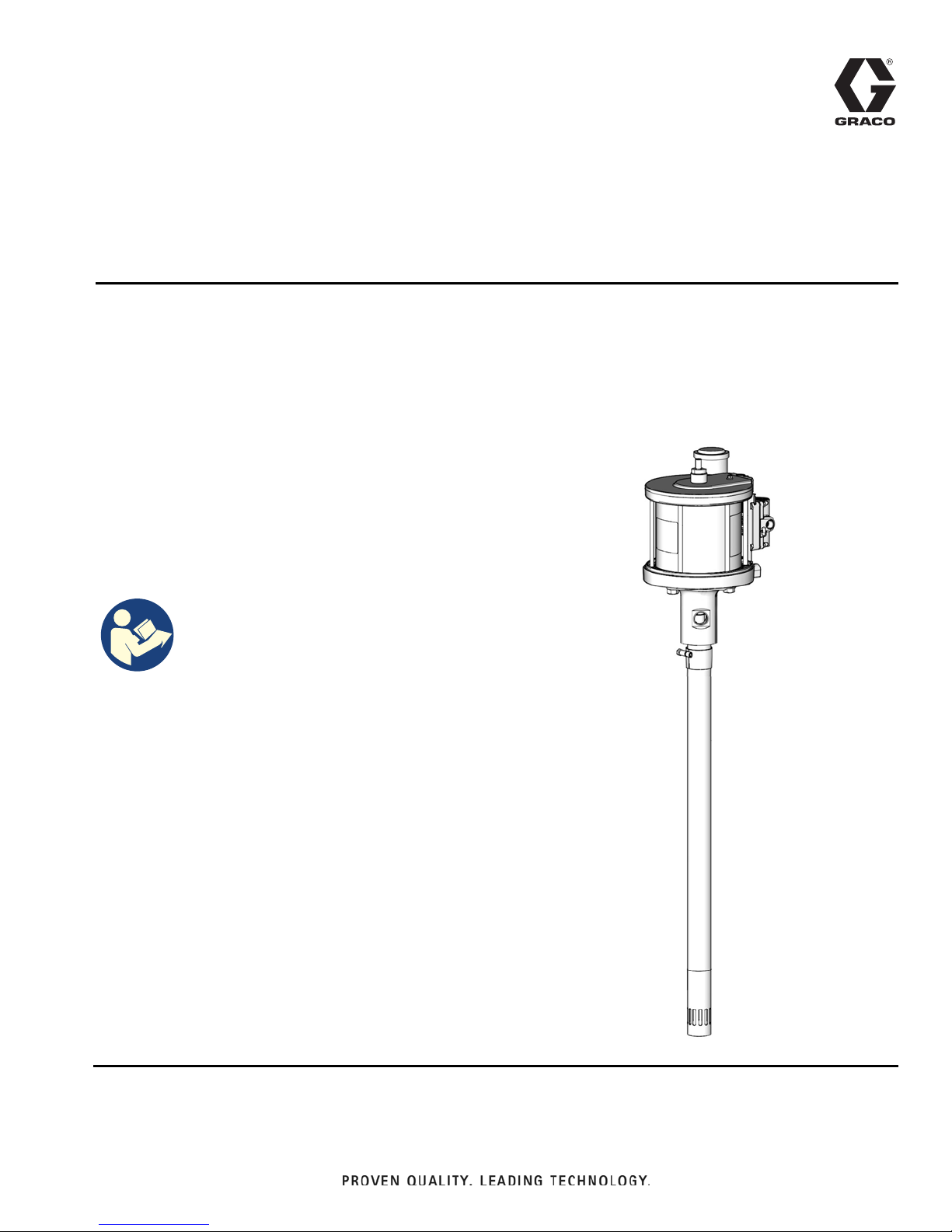
GT 750 Grease
3A5363B
Pump
For transferring grease using a medium pressure, high volume pump. For professional use
only.
Model No.:
24W337, Series A: 400 lb (180 kg) drum length
25D116, Series A: 120 lb (55 kg) drum length
24W498, Series A: stubby length
3600 psi (24.8 MPa, 248 bar) Maximum Working
Pressure
100 psi (0.7 MPa, 7 bar) Maximum Air Inlet Pressure
EN
Important Safety Instructions
Read all warnings and instructions in this
manual. Save these instructions.
Related Manuals
3A1211 SaniForce
™
Air Motor
Page 2
Warnings
WARNING
Warnings
The following warnings are for the setup, use, grounding, maintenance, and repair of this equipment. The exclamation point symbol alerts you to a general warning and the hazard symbols refer to procedure-specific risks. When
these symbols appear in the body of this manual or on warning labels, refer back to these Warnings. Product-specific
hazard symbols and warnings not covered in this section may appear throughout the body of this manual where
applicable.
SKIN INJECTION HAZARD
High-pressure fluid from dispensing device, hose leaks, or ruptured components will pierce skin. This
may look like just a cut, but it is a serious injury that can result in amputation. Get immediate surgi-
cal treatment.
• Do not point dispensing device at anyone or at any part of the body.
• Do not put your hand over the fluid outlet.
• Do not stop or deflect leaks with your hand, body, glove, or rag.
• Follow the Pressure Relief Procedure when you stop dispensing and before cleaning, checking,
or servicing equipment.
• Tighten all fluid connections before operating the equipment.
• Check hoses and couplings daily. Replace worn or damaged parts immediately.
FIRE AND EXPLOSION HAZARD
When flammable fluids are present in the work area, such as gasoline and windshield wiper fluid, be
aware that flammable fumes can ignite or explode. To help prevent fire and explosion:
• Use equipment only in well-ventilated area.
• Eliminate all ignition sources, such as cigarettes and portable electric lamps.
• Ground all equipment in the work area.
• Keep work area free of debris, including rags and spilled or open containers of solvent and gasoline.
• Do not plug or unplug power cords or turn lights on or off when flammable fumes are present.
• Use only grounded hoses.
• Stop operation immediately if static sparking occurs or you feel a shock. Do not use equipment
until you identify and correct the problem.
• Keep a working fire extinguisher in the work area.
2 3A5363B
Page 3
Warnings
WARNING
EQUIPMENT MISUSE HAZARD
Misuse can cause death or serious injury.
• Do not operate the unit when fatigued or under the influence of drugs or alcohol.
• Do not exceed the maximum working pressure or temperature rating of the lowest rated system
component. See Technical Specifications in all equipment manuals.
• Use fluids and solvents that are compatible with equipment wetted parts. See Technical Specifi-
cations in all equipment manuals. Read fluid and solvent manufacturer’s warnings. For complete
information about your material, request Safety Data Sheets (SDSs) from distributor or retailer.
• Turn off all equipment and follow the Pressure Relief Procedure when equipment is not in use.
• Check equipment daily. Repair or replace worn or damaged parts immediately with genuine manufacturer’s replacement parts only.
• Do not alter or modify equipment. Alterations or modifications may void agency approvals and create safety hazards.
• Make sure all equipment is rated and approved for the environment in which you are using it.
• Use equipment only for its intended purpose. Call your distributor for information.
• Route hoses and cables away from traffic areas, sharp edges, moving parts, and hot surfaces.
• Do not kink or over bend hoses or use hoses to pull equipment.
• Keep children and animals away from work area.
• Comply with all applicable safety regulations.
MOVING PARTS HAZARD
Moving parts can pinch, cut or amputate fingers and other body parts.
• Keep clear of moving parts.
• Do not operate equipment with protective guards or covers removed.
• Pressurized equipment can start without warning. Before checking, moving, or servicing equipment, follow the Pressure Relief Procedure and disconnect all power sources.
TOXIC FLUID OR FUMES HAZARD
Toxic fluids or fumes can cause serious injury or death if splashed in the eyes or on skin, inhaled, or
swallowed.
• Read Safety Data Sheets (SDSs) to know the specific hazards of the fluids you are using.
• Store hazardous fluid in approved containers, and dispose of it according to applicable guidelines.
PERSONAL PROTECTIVE EQUIPMENT
Wear appropriate protective equipment when in the work area to help prevent serious injury, including
eye injury, hearing loss, inhalation of toxic fumes, and burns. Protective equipment includes but is not
limited to:
• Protective eyewear, and hearing protection.
• Respirators, protective clothing, and gloves as recommended by the fluid and solvent manufacturer.
3A5363B 3
Page 4
Installation
A
B
C
D
E
F
H
K
J
G
L
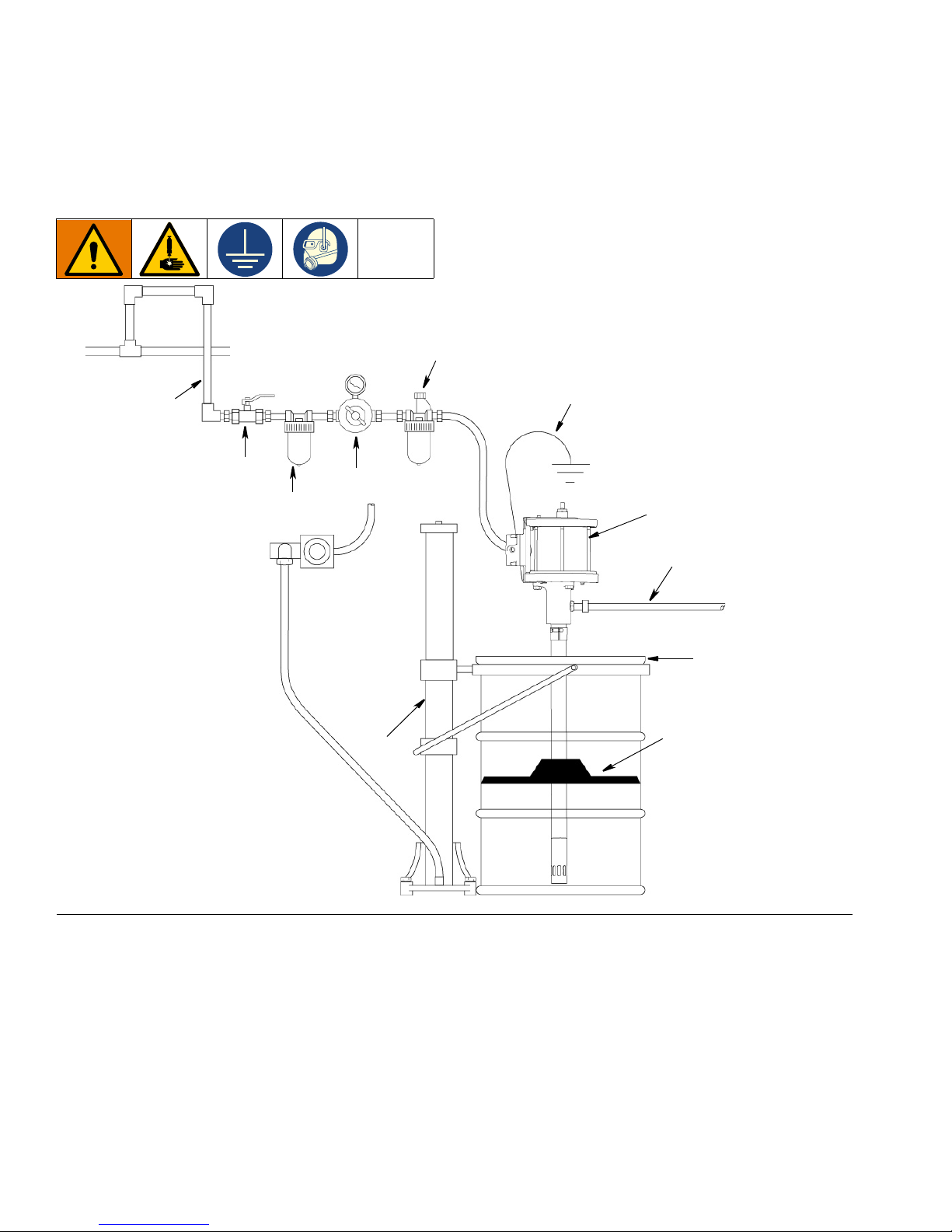
Installation
Typical Installation
FIG. 1
Key:
A Grounded Air Line
B Bleed-type Master Air Valve
CAir Filter
D Air Line Oiler
E Air Regulator
F Fluid Hose
G Elevator Assembly
H Ground Wire
J Follower Plate
K Drum Cover
L Air Motor
4 3A5363B
Page 5
Installation
Z
Y
Installation Instructions
NOTE: The reference letters in the following instructions
refer to the Typical Installation illustration, page 4.
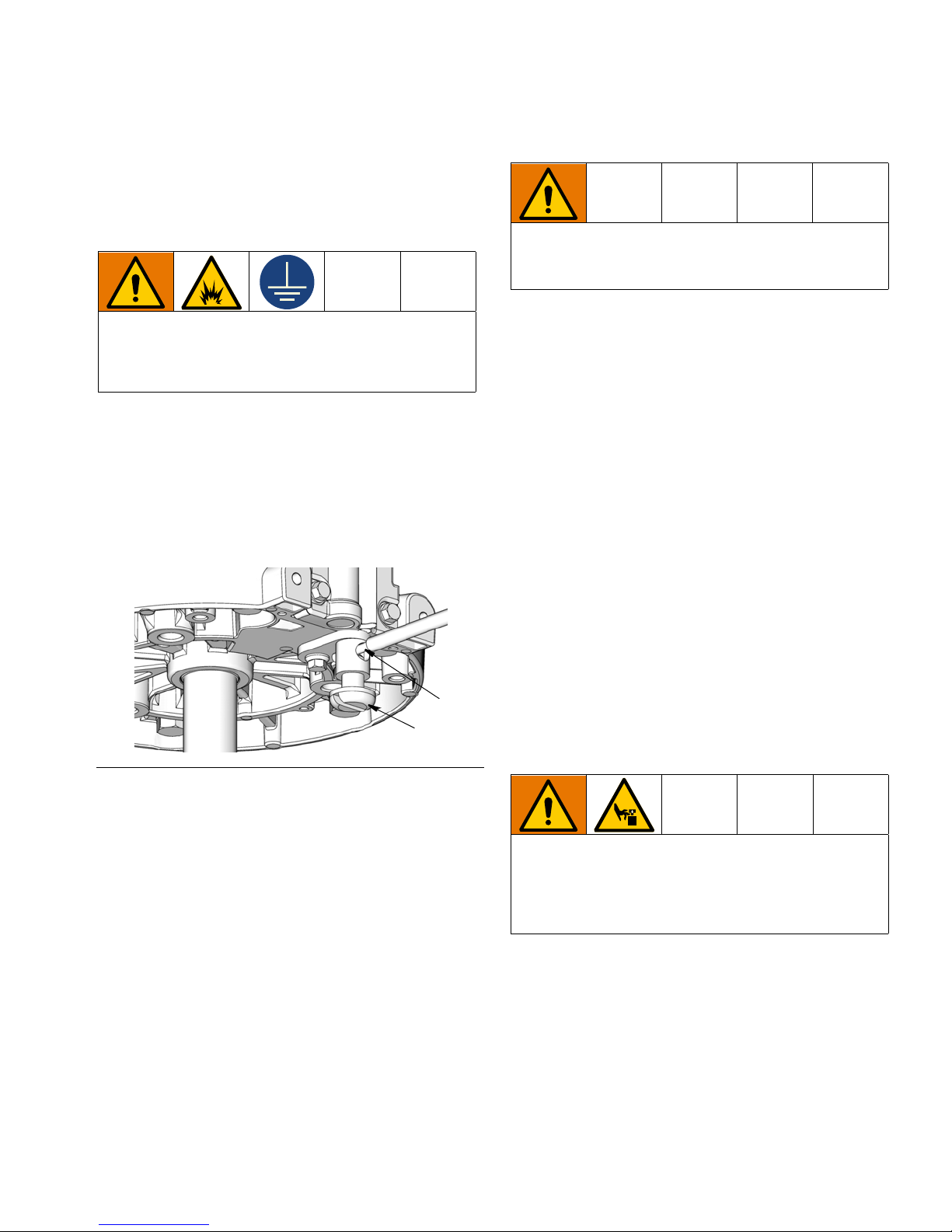
Grounding
The equipment must be grounded to reduce the risk
of static sparking. Static sparking can cause fumes to
ignite or explode. Grounding provides an escape wire
for the electric current.
Pump: use ground wire and clamp (as shown in FIG. 2).
Connect the other end of the ground wire to a true earth
ground.
1. Remove the ground screw (Z) and insert through
eye of the ring terminal at end of ground wire (Y).
2. Fasten the ground screw (Z) back into the pump and
tighten securely.
Mounting the Pump
Mount the pump securely so that it cannot move
around during operation. Failure to do so could
result in personal injury or equipment damage.
• Select a convenient installation location for the
equipment to ensure easy operator access to the
pump air controls, sufficient room to change supply
containers, and a secure mounting platform.
• If you are mounting the pump directly on the supply
tank, position the pump so its intake valve is no
more than 1 in. (25 mm) from the bottom of the container. Mount the pump to the cover or other suitable
mounting device.
• Mount the pump to suit the type of installation
planned. Very heavy lubricants may require an
inductor plate.
FIG. 2
Air and fluid hoses: use only electrically conductive
hoses.
Air compressor: follow manufacturer’s recommendations.
Dispense valve: ground through connection to a properly grounded fluid hose and pump.
Solvent pails used when flushing: follow local code.
Use only conductive metal pails, placed on a grounded
surface. Do not place the pail on a non-conductive surface, such as paper or cardboard, which interrupts
grounding continuity.
To maintain grounding continuity when flushing or
relieving pressure: hold metal part of the dispense
valve firmly to the side of a grounded metal pail, then
trigger the valve.
• Install the air line accessories as shown in the Typical Installation, page 4. Install a bleed-type master
air valve (B) within easy reach of the pump,
upstream from the air regulator. Install an air filter
(C) to remove harmful dirt and moisture from your
compressed air supply. For automatic air motor
lubrication, install an air line oiler (D) close to the
pump air inlet. Install an air regulator (E) to control
pump speed.
A bleed-type master air valve (B) is required to shut
off and relieve air pressure that may be trapped in the
air motor. Trapped air could cause the pump to cycle
unexpectedly and cause serious bodily injury, including amputation.
• Be sure the air hose is properly sized to deliver an
adequate supply of air to the motor. Refer to the
Technical Data on page 15.
• Connect a dispensing hose to the pump outlet.
Install an appropriate dispensing valve to the hose.
• Ground the pump as explained on page 5.
3A5363B 5
Page 6
Operation
Operation
NOTE: The reference letters in the following instructions
refer to the Typical Installation illustration, page 4.
This pump is designed to be used only in pumping
non-corrosive and non-abrasive lubricants. Any
other use of the pump can cause unsafe operating
conditions and component rupture, which can result
in fluid injection or other serious injury or fire or
explosion.
Pressure Relief Procedure
Follow the Pressure Relief Procedure whenever
you see this symbol.
This equipment stays pressurized until pressure is
manually relieved. To help prevent serious injury from
pressurized fluid, such as skin injection, splashing
fluid and moving parts, follow the Pressure Relief Procedure when you stop dispensing and before cleaning, checking, or servicing the equipment.
Priming and Pump Speed
Adjustment
1. Open the bleed-type master air valve (B).
2. Open the dispensing valve, and slowly open the air
regulator (E) until the pump is running smoothly.
3. After all the air is purged, close the dispensing
valve.
The pump will start and stop as the valve is opened
and closed.
4. Use the air regulator (E) to control the pump speed
and fluid pressure. Always use the lowest pressure
necessary to obtain the desired results.
5. If the pump accelerates quickly or is running too
fast, stop it immediately and check the fluid supply. If
the supply container is empty and air has been
pumped into the lines:
a. Refill the supply container.
b. Prime the pump and fill the lines with fluid to
remove all the air from the fluid lines.
1. Close the supply pump’s bleed-type master air valve
(B) (required in the system).
2. Open the dispensing valve until the pressure is fully
relieved.
6 3A5363B
Never allow the pump to run dry of the fluid being
pumped. A dry pump quickly accelerates to a high
speed and may damage itself. If your pump accelerates quickly or is running too fast, stop it immediately
and check the fluid supply. If the supply container is
empty and air has been pumped into the lines, prime
the pump and lines with fluid, or flush the pump and
leave it filled with a compatible solvent. Be sure to
eliminate all air from the fluid system.
NOTICE
Page 7

Troubleshooting
NOTE: Check all other possible problems and solutions before you disassemble the pump.
Problem Cause Solution
Inadequate air supply pressure Increase air supply.
Restricted air line Clear line.
Closed dispensing valve Open valve.
Clogged fluid lines, hoses, and/or
dispense valve
1. Follow Pressure Relief Procedure, page 6.
Troubleshooting
Pump fails to operate or there is no
fluid flow
Damaged air motor Service air motor. See SaniForce Air
Exhausted fluid supply Refill and prime or flush.
Continuous air exhaust Worn or damaged air motor gasket,
packing, seal, etc.
Exhausted fluid supply Refill and prime or flush.
Erratic pump operation
Pump operates but output low on
down stroke
Fluid is coming out of the muffler Worn or damaged throat seal Replace worn seals. See Service,
Held open or worn intake valve or
piston seals
Inadequate air supply pressure Increase air supply.
Held open or worn intake valve or
piston seals
2. Disconnect fluid line.
3. Turn on air. If the pump starts
when the air is turned again, the
line, hose, and/or valve is
clogged. Clear obstruction.
Motor manual.
Service air motor. See SaniForce Air
Motor manual.
Replace worn seals. See Service,
page 8.
Replace worn seals. See Service,
page 8.
page 8.
3A5363B 7
Page 8

Service
1528
14*
10
8
20
10
8
Service
Before You Start
• Be sure you have all necessary parts on hand. Use
Graco repair kit 25D511. Use all parts in the kit for
best results.
• Parts included in the kit are marked with one asterisk, for example (19*), in the text and drawings.
• Clean and inspect all parts for wear or damage as
you disassemble them. Replace parts as needed.
• For best results, always use all new parts included
in kit to replace all the o-rings and packings when
you disassemble the pump.
Displacement Pump Service
Disassembly
1. Flush the pump.
2. Relieve pressure, page 6.
3. Disconnect fluid and air lines from pump and
remove pump from its installation location.
4. Clamp the air motor base (21) in a vise horizontally
by closing the vise jaws on the flange.
5. Insert a wrench through a slot in the foot valve (10)
and secure it around the flats of the piston shovel
rod (8). While holding the piston shovel rod securely
in place, use a second wrench to loosen and
remove jam nut (15). Remove washer (28), and
priming plate (14) from shovel rod (F
NOTE: Using a wrench to hold the piston shovel rod
(8) in place during this procedure will prevent it from
unscrewing from the piston housing (7).
IG. 3).
FIG. 3
6. Unscrew foot valve housing (10) from cylinder (20)
(F
IG. 4).
NOTE: Poppet check (12), foot valve packings (13),
and bearing (11) slide off priming rod (8) when
removing foot valve housing.
8 3A5363B
FIG. 4
Page 9

Service
12
11
13
10
20
21
5
6
4
23
21
2
7. Unscrew bearing (11) from foot valve housing.
Remove the poppet check (12) and inspect foot
valve packings (13) (F
IG. 5).
9. Loosen nut (5) and unscrew the valve housing (6)
from connecting rod (4) (F
IG. 7).
FIG. 7
10. Unscrew bolts (23) that connect pump base (21) to
the air motor (F
IG. 8).
FIG. 5
8. Unscrew down tube (20) from pump base (21) (F
6).
Clean the tube and inspect it for wear by holding it
up to a light at a slight angle. If you see wavy lines
or scratches where the piston travels, replace the
tube as it will not seal well with the new piston seal
and the pump will perform poorly.
FIG. 6
IG.
11. Remove pump base (21) from air motor and
unscrew packing gland (2) (F
IG. 8).
FIG. 8
12. Remove the following seals and inspect: piston seal
(22), o-ring (17), o-ring (29), throat seal (19), o-ring
(16) from the pump base (21) (See Parts, page 13).
13. Clean and inspect all parts.
3A5363B 9
Page 10

Service
21
29
19*
2
17
*
21
23
22*
7
4
6
5
20
21
Reassembly
1. Apply a thin layer of grease to o-ring (17*) and
throat seal (19*)and install parts in pump base (21)
(F
IG. 9).
2. Apply a thin layer of grease to o-ring (29*) and
install o-ring to packing gland (2). Tighten down
packing gland (2) to pump base (F
NOTE: Throat seal (19*) should be installed with the
lips pointed down towards the bottom of the pump.
IG. 9).
4. Replace piston seal (22*) on valve housing piston
IG. 11).
(7) (F
5. Screw the connecting rod (4) into the valve housing
(6) and adjust the ball travel as instructed in Check
Valve Adjustment on page 12 Tighten nut (5) to 60
ft-lb (81.35 N•m) (F
IG. 11).
FIG. 11
6. Apply a thin layer of grease to piston seal (22*).
Reinstall down tube (20) into pump base (21).
Torque to 100 to 150 ft-lb (135.6 to 203.4 N•m) (F
12).
FIG. 9
3. Reattach pump base (21) to air motor (1) using 3
mounting bolts (23). Torque mounting bolts to 60
ft-lb (81.35 N•m) (F
IG. 10).
FIG. 10
10 3A5363B
FIG. 12
IG.
Page 11

Service
11
8
13*
13*
12
16*
20
10
10
9
8
28
15*
For Steps 7 to 12 refer to FIG. 13.
7. Slide bearing (11) onto priming rod (8) with the step
side facing the bottom of the pump.
8. Insert foot valve packings (13*) into poppet check
(12).
9. Slide poppet check containing foot valve packings
onto priming rod (8) with beveled edge facing the
bottom of the pump.
10. Apply a thin layer of grease to o-ring (16*) and
install o-ring on foot valve (10).
11. Slide foot valve over poppet check and screw bearing (11) into the foot valve (10).
12. Push foot valve up to the down tube (20) and screw
in place.
13. Slide priming plate (9) (beveled edge up), followed
by washer (28), onto priming rod (8). Insert a
wrench through a slot in the foot valve (10) and
secure it around the flats of the piston shovel rod
(8). While holding the piston shovel rod securely in
place, use a second wrench to tighten jam nut (15*)
to 10 ft-lb (13.5 N•m).
NOTE: Jam nut (15*) should be replaced each time
it is removed from priming rod.
FIG. 13
FIG. 14
14. Reconnect the pump’s ground wire to a true earth
ground.
3A5363B 11
Page 12

Service
5
6
Check Valve Adjustment
This pump has an adjustable piston ball check.
To change the piston ball travel:
1. Relieve pressure, page 6.
2. Loosen nut (5).
3. Turn the piston valve housing (6) counterclockwise
to increase the ball travel and clockwise to
decrease the ball travel.
NOTE: The factory setting is a 0.225” ball travel.
Decreasing the ball travel can minimize surging at
stroke changeover; however, a travel that is too
short restricts the flow and slows down the pump.
FIG. 15
4. Tighten nut (5). Torque to 60 ft-lb (81.35 N•m).
12 3A5363B
Page 13

Parts
2
19
3
21
23
24
17
5
4
5
6
9
22
13
13
12
8
20
16
10
14
15
7
11
29
1
28
30
18
31
33
32
Parts
3A5363B 13
Page 14

Parts
Parts
Ref Part Description Qty
1 24R015 MOTOR, assy, air, 7.5 in,
2 17C099 GLAND, packing
3 17C098 SPACER, throat
17C102 ROD, connecting, model
24W337
17C254 ROD, connecting, stubby,
4
131240 ROD, connecting, 120 lb,
5 100155 NUT
6 17C101 HOUSING, valve
7 17C097 HOUSING, valve piston
8 17C103 ROD, piston, shovel
9 100279 BALL, metallic
10 17U190 VALVE, foot
11 624943 BEARING, rod guide 10:1
12 17U133 POPPET, foot, valve
13* PACKING, foot valve
14* PLATE, priming aluminum
15* NUT, jam, hex, heavy, 5/16
16* PACKING, o-ring
17* PACKING, o-ring
18 222308 ADAPTER, bung 2" NPT
19* SEAL, piston rod
17C096 CYLINDER, pump, model
17C256 CYLINDER, pump, stubby,
20
131239 CYLINDER, pump 120 lb,
21 17C095 HOUSING, adapter,
model 24W498
model 25D116
shovel
24W337
model 24W498
model 25D116
machined
Ref Part Description Qty
1
1
1
1
1
1
2
1
1
1
1
1
1
1
2
1
1
1
1
1
1
1
1
1
1
22* SEAL, cylinder, double acting
23 123208 SCREW, cap, hex head
24 17C100 FITTING, connecting rod
28 100023 WASHER, flat
29* PACKING, o-ring
30 158674 PACKING, o-ring
31 117237 MUFFLER
32 100896 FITTING, bushing, pipe
33 115764 FITTING, elbow, 90°
34 130447 LABEL, identification
35 130452 LABEL, safety, warning (not
shown)
Replacement Danger and Warning labels, tags and
cards are available at no cost.
* Parts are included in Pump Lower Repair Kit
25D511.
Accessories
Part Description
16C009 RING, lift
131394 ADAPTER, female cam lock, 3 in. (f)
cam lock x 2 in. (f) NPT
131380 ADAPTER, male cam lock, 3 in. (m)
cam lock x 2 in. (f) NPT
24A592
223701 PLATE, follow, 400 lb.
KIT, DataTrak
®
cycle count
1
3
1
1
1
1
1
1
1
1
1
14 3A5363B
Page 15

Technical Specifications
Technical Specifications
GT 750 Pump
US Metric
Fluid Pressure Ratio 36:1
Air Pressure Operating Range 40-100 psi 0.3 - 0.7 MPa (3-7 bar)
Maximum Working Pressure 3600 psi 24.8 MPa (248 bar)
Maximum recommended pump speed
Air Motor Effective Diameter 7.5 in. 190 mm
Stroke 4.75 in. 121 mm
Air Inlet 1/2 in. NPT
Fluid Outlet 1 in. NPT
Maximum Delivery 30 lbs/minute 13.6 kg/minute
Pump Weight 59 lbs. 26.76 kg
Wetted Parts steel, brass, Buna-N, urethane, ductile iron, aluminum
Sound Power (Measured at 70 psi (0.48 MPa,
4.8 bar), 20 CPM. Sound Power is measured
per ISO-9414-2)
Sound Pressure (Tested at 3.28 ft (1 M) from
equipment.
Pump Cycles Per Pound 3 cycles
Pump Cycles Per KG 6 cycles
60 cycles per minute
77.2 dBa
70.5 dBa
Performance Curve
3A5363B 15
Page 16

Technical Specifications
400lb Drum 120 lb Drum Stubby
Dimensions
Dimension Table
Ref Description
A Air Inlet, 1/2 inch NPT
B Fluid Outlet, 1 inch NPT
C 2 inch NPT mounting adapter
16 3A5363B
Page 17

Notes
Notes
3A5363B 17
Page 18

Graco Standard Warranty
Graco warrants all equipment referenced in this document which is manufactured by Graco and bearing its name to be free from defects in
material and workmanship on the date of sale to the original purchaser for use. With the exception of any special, extended, or limited warranty
published by Graco, Graco will, for a period of twelve months from the date of sale, repair or replace any part of the equipment determined by
Graco to be defective. This warranty applies only when the equipment is installed, operated and maintained in accordance with Graco’s written
recommendations.
This warranty does not cover, and Graco shall not be liable for general wear and tear, or any malfunction, damage or wear caused by faulty
installation, misapplication, abrasion, corrosion, inadequate or improper maintenance, negligence, accident, tampering, or substitution of
non-Graco component parts. Nor shall Graco be liable for malfunction, damage or wear caused by the incompatibility of Graco equipment with
structures, accessories, equipment or materials not supplied by Graco, or the improper design, manufacture, installation, operation or
maintenance of structures, accessories, equipment or materials not supplied by Graco.
This warranty is conditioned upon the prepaid return of the equipment claimed to be defective to an authorized Graco distributor for verification of
the claimed defect. If the claimed defect is verified, Graco will repair or replace free of charge any defective parts. The equipment will be returned
to the original purchaser transportation prepaid. If inspection of the equipment does not disclose any defect in material or workmanship, repairs will
be made at a reasonable charge, which charges may include the costs of parts, labor, and transportation.
THIS WARRANTY IS EXCLUSIVE, AND IS IN LIEU OF ANY OTHER WARRANTIES, EXPRESS OR IMPLIED, INCLUDING BUT NOT LIMITED
TO WARRANTY OF MERCHANTABILITY OR WARRANTY OF FITNESS FOR A PARTICULAR PURPOSE.
Graco’s sole obligation and buyer’s sole remedy for any breach of warranty shall be as set forth above. The buyer agrees that no other remedy
(including, but not limited to, incidental or consequential damages for lost profits, lost sales, injury to person or property, or any other incidental or
consequential loss) shall be available. Any action for breach of warranty must be brought within two (2) years of the date of sale.
GRACO MAKES NO WARRANTY, AND DISCLAIMS ALL IMPLIED WARRANTIES OF MERCHANTABILITY AND FITNESS FOR A
PARTICULAR PURPOSE, IN CONNECTION WITH ACCESSORIES, EQUIPMENT, MATERIALS OR COMPONENTS SOLD BUT NOT
MANUFACTURED BY GRACO. These items sold, but not manufactured by Graco (such as electric motors, switches, hose, etc.), are subject to
the warranty, if any, of their manufacturer. Graco will provide purchaser with reasonable assistance in making any claim for breach of these
warranties.
In no event will Graco be liable for indirect, incidental, special or consequential damages resulting from Graco supplying equipment hereunder, or
the furnishing, performance, or use of any products or other goods sold hereto, whether due to a breach of contract, breach of warranty, the
negligence of Graco, or otherwise.
FOR GRACO CANADA CUSTOMERS
The Parties acknowledge that they have required that the present document, as well as all documents, notices and legal proceedings entered into,
given or instituted pursuant hereto or relating directly or indirectly hereto, be drawn up in English. Les parties reconnaissent avoir convenu que la
rédaction du présente document sera en Anglais, ainsi que tous documents, avis et procédures judiciaires exécutés, donnés ou intentés, à la suite
de ou en rapport, directement ou indirectement, avec les procédures concernées.
Graco Information
For the latest information about Graco products, visit www.graco.com.
For patent information, see www.graco.com/patents.
TO PLACE AN ORDER, contact your Graco distributor or call to identify the nearest distributor.
Phone: 612-623-6928 or Toll Free: 1-800-533-9655, Fax: 612-378-3590
All written and visual data contained in this document reflects the latest product information available at the time of publication.
GRACO INC. AND SUBSIDIARIES • P.O. BOX 1441 • MINNEAPOLIS MN 55440-1441 • USA
Copyright 2017, Graco Inc. All Graco manufacturing locations are registered to ISO 9001.
Graco reserves the right to make changes at any time without notice.
Original instructions. This manual contains English. MM3A5363
Graco Headquarters: Minneapolis
International Offices: Belgium, China, Japan, Korea
www.graco.com
Revision
B, April 2018
 Loading...