

Page 1
Instructions-Parts
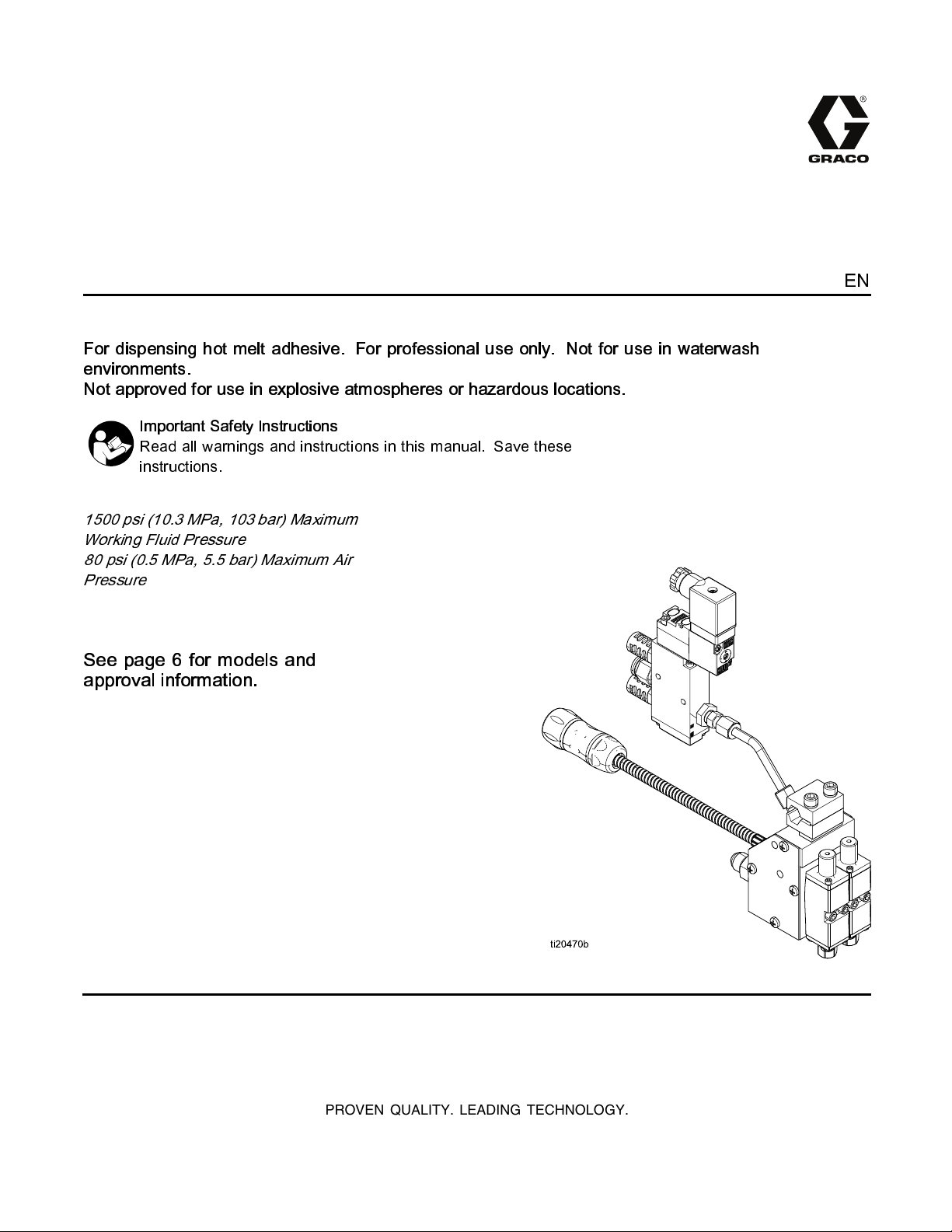
InvisiPac® GS35 Plug-Free™
Hot Melt Applicator
For dispensing hot melt adhesive. For professional use only. Not for use in waterwash
environments.
Not approved for use in explosive atmospheres or hazardous locations.
Important Safety Instructions
Read all warnings and instructions in this manual. Save these
instructions.
1500 psi (10.3 MPa, 103 bar) Maximum
Working Fluid Pressure
80 psi (0.5 MPa, 5.5 bar) Maximum Air
Pressure
See page 6 for models and
approval information.
3A2805K
EN
PROVEN QUALITY. LEADING TECHNOLOGY.
Page 2
Contents
Warnings ........................................................... 3
Approvals........................................................... 5
Models............................................................... 6
Component Identification..................................... 7
Overview............................................................ 8
Grounding.......................................................... 8
Installation.......................................................... 9
Mounting ..................................................... 9
Connect Heated Hose.................................. 9
Connect Solenoid Valve ............................... 9
Connect Triggering Device ........................... 10
Prime Before Using Equipment..................... 10
Flush........................................................... 11
Install Nozzle ............................................... 11
Select RTD.................................................. 11
Operation ........................................................... 12
Pressure Relief Procedure............................ 12
Maintenance ...................................................... 13
Replace Inlet Filter ....................................... 13
Filter Maintenance Guidelines....................... 13
Troubleshooting..................................................14
Check Module..............................................16
Check Nozzle and Module............................ 16
Check Heater .............................................. 17
Check RTD..................................................17
Check Thermal Cutoff .................................. 18
Repair................................................................ 19
Before Beginning Repair...............................19
Replace Heater Cartridge............................. 20
Replace RTD ............................................... 20
Replace Thermal Cutoff................................ 20
Replace Cordset.......................................... 22
Replace Solenoid Valve ............................... 24
Replace Module........................................... 24
Replace Applicator....................................... 24
Notes ................................................................ 25
Parts.................................................................. 26
Kits and Accessories...........................................44
Dimensions........................................................ 46
Technical Data...................................................50
Notes ................................................................ 51
Graco Extended Warranty ................................... 52
2
3A2805K
Page 3
Warnings
Warnings
The following warnings are for the setup, use, grounding, maintenance, and repair of this equipment. The
exclamation point symbol alerts you to a general warning and the hazard symbols refer to procedure-specific
risks. When these symbols appear in the body of this manual or on warning labels, refer back to these
Warnings. Product-specific hazard symbols and warnings not covered in this section may appear throughout
the body of this manual where applicable.
WARNING
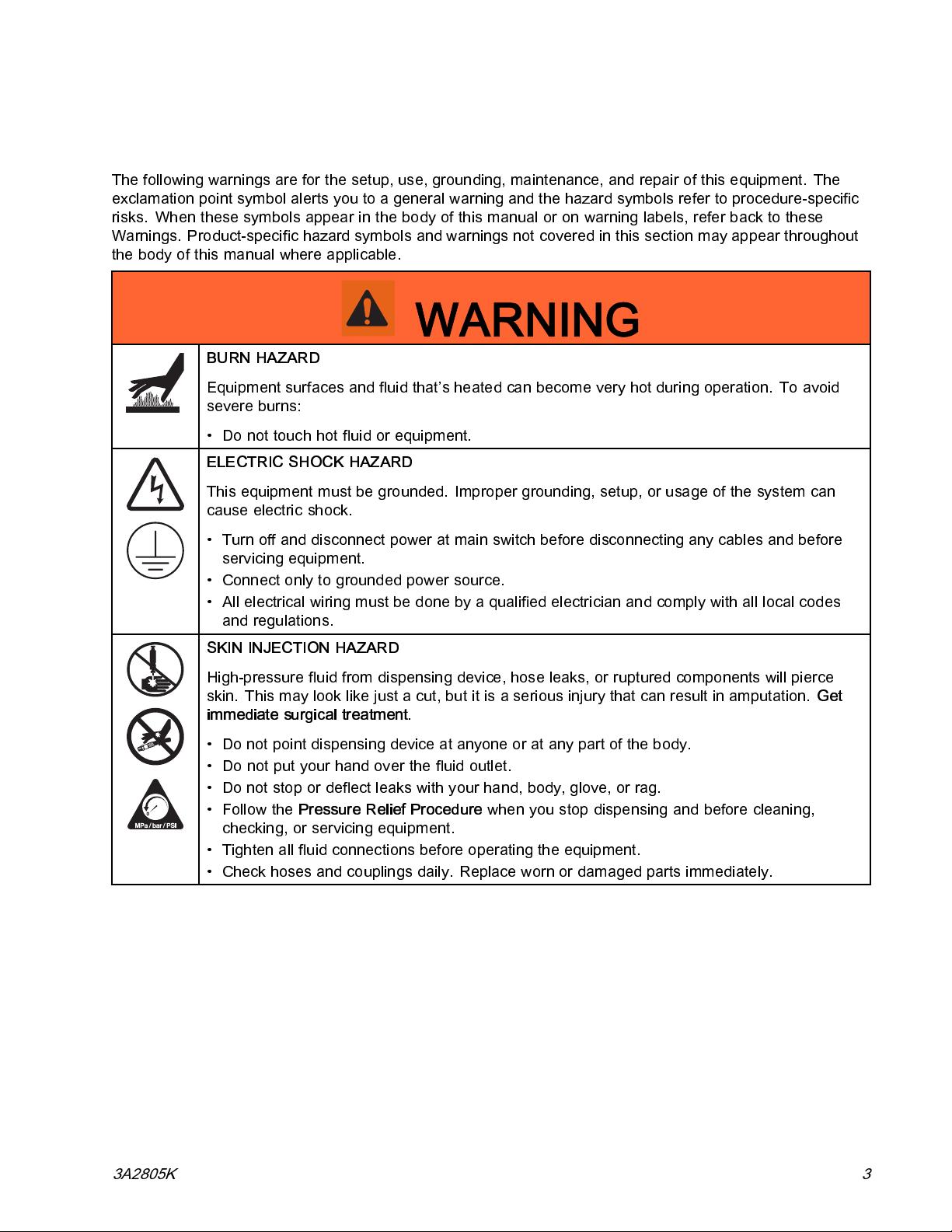
BURN HAZARD
Equipment surfaces and fluid that’s heated can become very hot during operation. To avoid
severe burns:
• Do not touch hot fluid or equipment.
ELECTRIC SHOCK HAZARD
This equipment must be grounded. Improper grounding, setup, or usage of the system can
cause electric shock.
• Turn off and disconnect power at main switch before disconnecting any cables and before
servicing equipment.
• Connect only to grounded p ower source.
• All electrical wiring must be done by a qualified electrician and comply with all local codes
and regulations.
SKIN INJECTION HAZARD
High-pressure fluid from dispensing device, hose leaks, or ruptured components will pierce
skin. This may look like just a cut, but it is a serious injury that can result in amputation.
immediate surgical treatment.
• Do not point dispensing device at anyone or at any part of the body.
• Do not put your hand over the fluid outlet.
• Do not stop or deflect leaks with your hand, body, glove, or rag.
•Followthe
checking, or servicing equipment.
• Tighten all fluid connections before operating the equipment.
• Check hoses and couplings daily. Replace worn or damaged parts immediately.
Pressure Relief Procedure
when you stop dispensing and before cleaning,
Get
3A2805K 3
Page 4
Warnings
WARNING
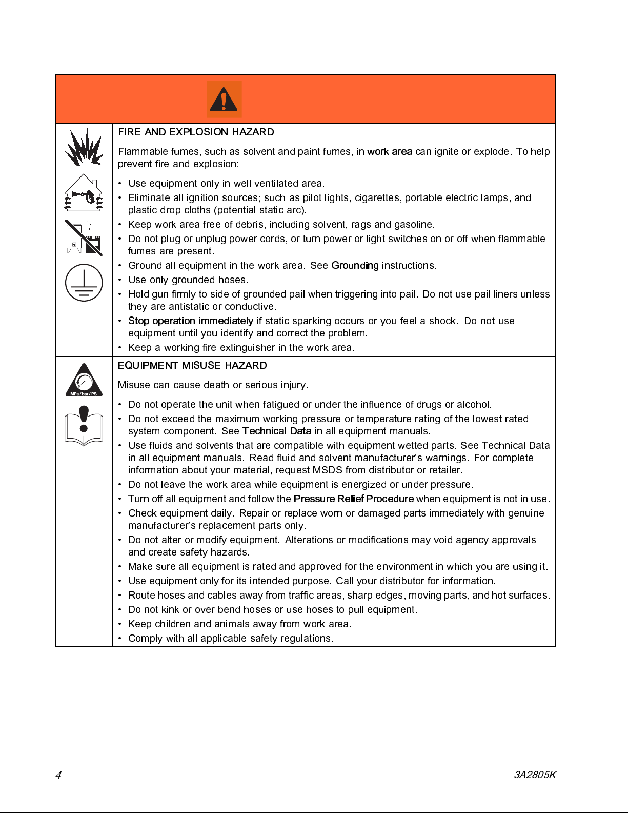
FIRE AND EXPLOSION HAZARD
Flammable fumes, such as solvent and paint fumes, in
prevent fire and explosion:
• Use equipment only in well ventilated area.
• Eliminate all ignition sources; such as pilot lights, cigarettes, portable electric lamps, and
plastic drop cloths (potential static arc).
• Keep work area free of debris, including solvent, rags and gasoline.
• Do not plug or unplug power cords, or turn powe r or light switches on or off when flammable
fumes are present.
• Ground all equipment in the work area. See
• Use only grounded hoses.
• Hold gun firmly to side of grounded pail when triggering into pail. Do not use pail liners unless
they are antistatic or conductive.
•
Stop operation immediately
equipment until you identify and correct the problem.
• Keep a working fire extinguisher in the work area.
EQUIPMENT MISUSE HAZARD
Misuse can cause death or serious injury.
• Do not operate the unit when fatigued or under the influence of drugs or alcohol.
• Do not exceed the maximum working pressure or temperature rating of the lowest rated
system component. See
• Use fluids and solvents that are compatible with equipment wetted parts. See Technical Data
in all equipment manuals. Read fluid and solvent manufacturer’s warnings. For complete
information about your material, request MSDS from distributor or retailer.
• Do not leave the work area while equipment is energized or under pressure.
• Turn off all equipment and follow the
• Check equipment daily. Repair or replace worn or damaged parts immediately with genuine
manufacturer’s replacement parts only.
• Do not alter or modify equipment. Alterations or modifications may void agency approvals
and create safety hazards.
• Make sure all equipment is rated and approved for the environment in which you are using it.
• Use equipment only for its intended purpose. Call your distributor for information.
• Route hoses and cables away from traffic areas, sharp edges, moving parts, and hot surfaces.
• Do not kink or over bend hoses or use hoses to pull equipment.
• Keep children and animals away from work area.
• Comply with all applicable safety regulations.
if static sparking occurs or you feel a shock.Do not use
Technical Data
Pressure Relief Procedure
Grounding
in all equipment manuals.
work area
instructions.
canigniteorexplode.Tohelp
when equipment is not in use.
4
3A2805K
Page 5

Approvals
WARNING
TOXIC FLUID OR FUMES HAZARD
Toxic fluids or fumes can cause serious injury or death if splashed in the eyes or on skin,
inhaled, or swallowed.
• Read MSDSs to know the specific hazards of the fluids you are using.
• Store hazardous fluid in approved containers, and dispose of it according to applicable
guidelines.
PERSONAL PROTECTIVE EQUIPMENT
Wear appropriate protective equipment when in the work area to help prevent serious injury,
including eye injury, hearing loss, inhalation of toxic fumes, and burns. This protective
equipment includes but is not limited to:
• Protective eyewear, and hearing protection.
• Respirators, protective clothing, and gloves as recommended by the fluid and solvent
manufacturer.
Approvals
4002346
Conforms to ANSI/UL Std.
499 Certified to CAN/CSA
Std. C22.2 No. 88
3A2805K 5
Page 6
Models
Models
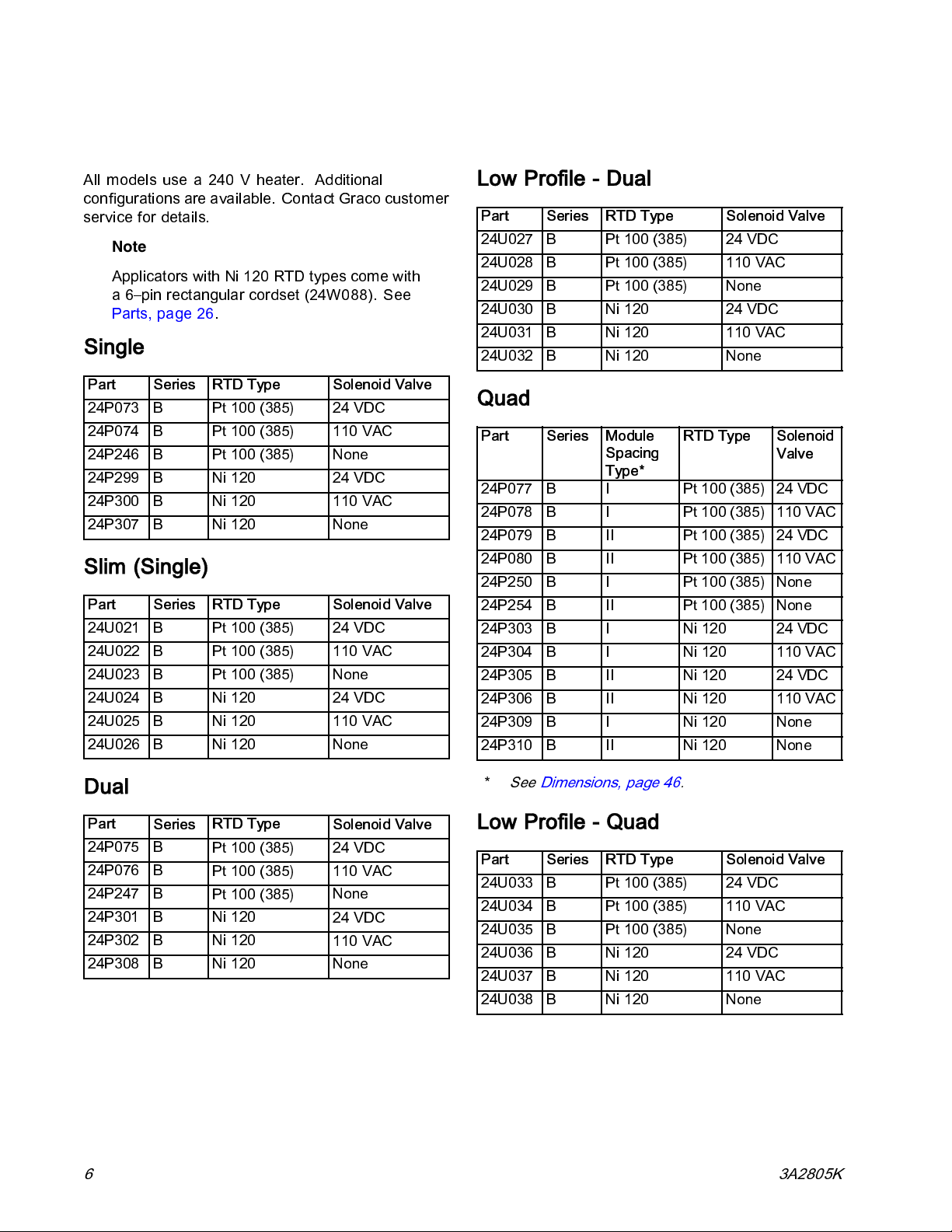
All models use a 240 V heater. Additional
configurations are available. Contact Graco customer
service for details.
Note
Applicators with Ni 120 RTD types come with
a 6–pin rectangular cordset (24W088). See
Parts, page 26.
Single
Part
24P073 B
24P074 B
24P246 B
24P299 B Ni 120
24P300 B Ni 120
24P307 B Ni 120 None
Series
RTD Type
Pt 100 (385) 24 VDC
Pt 100 (385) 110 VAC
Pt 100 (385)
Solenoid Valve
None
24 VDC
110 VAC
Slim (Single)
Part
24U021 B
24U022 B
24U023 B
24U024 B Ni 120
24U025 B Ni 120
24U026 B Ni 120 None
Series
RTD Type
Pt 100 (385) 24 VDC
Pt 100 (385) 110 VAC
Pt 100 (385)
Solenoid Valve
None
24 VDC
110 VAC
Low Profile - Dual
Part
24U027 B
24U028 B
24U029 B
24U030 B Ni 120
24U031 B Ni 120
24U032 B Ni 120 None
Series
RTD Type
Pt 100 (385) 24 VDC
Pt 100 (385) 110 VAC
Pt 100 (385)
Solenoid Valve
None
24 VDC
110 VAC
Quad
Part
24P077 B I
24P078 B I
24P079 B II
24P080 B II
24P250 B I
24P254 B II
24P303 B I Ni 120
24P304 B I Ni 120
24P305 B II Ni 120
24P306 B II Ni 120
24P309 B I Ni 120 None
24P310 B II Ni 120 None
Series
Module
Spacing
Type*
RTD Type
Pt 100 (385) 24 VDC
Pt 100 (385) 110 VAC
Pt 100 (385) 24 VDC
Pt 100 (385) 110 VAC
Pt 100 (385)
Pt 100 (385)
Solenoid
Valve
None
None
24 VDC
110 VAC
24 VDC
110 VAC
*
Dual
Part
24P075 B
24P076 B
24P247 B
24P301 B Ni 120
24P302 B Ni 120
24P308 B Ni 120 None
Series
RTD Type
Pt 100 (385) 24 VDC
Pt 100 (385) 110 VAC
Pt 100 (385)
Solenoid Valve
None
24 VDC
110 VAC
See Dimensions, page 46.
Low Profile - Quad
Part Series RTD Type Solenoid Valve
24U033 B Pt 100 (385) 24 VDC
24U034 B Pt 100 (385) 110 VAC
24U035 B Pt 100 (385) None
24U036 B Ni 120 24 VDC
24U037 B Ni 120 110 VAC
24U038 B Ni 120 None
6 3A2805K
Page 7
Component Identification
Component Identification
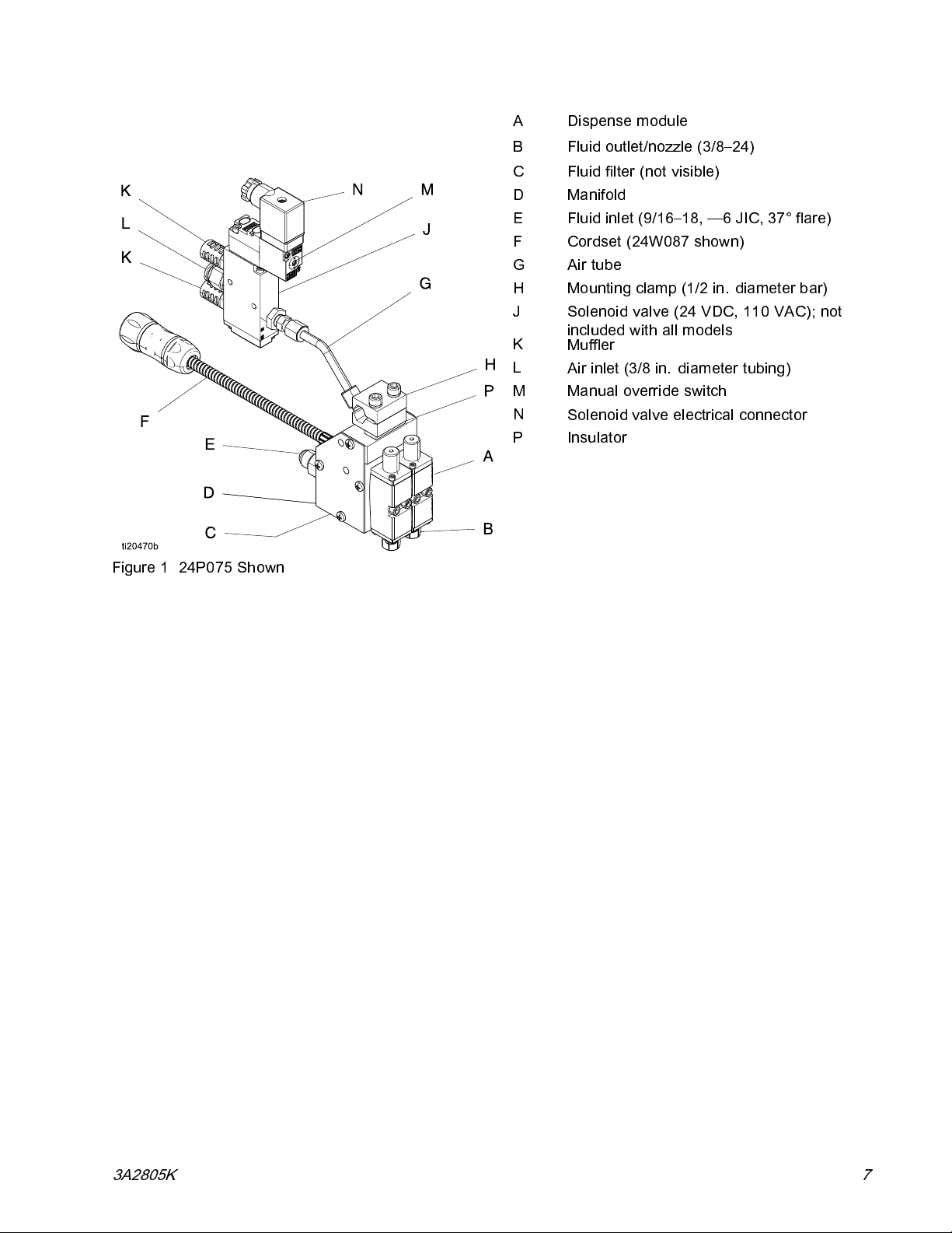
Figure 1 24P075 Shown
A Dispense module
B
C Fluid filter (not visible)
D
E
F
G
H
J
K
L
M Manual override switch
N
P Insulator
Fluid outlet/nozzle (3/8–24)
Manifold
Fluid inlet (9/16–18, —6 JIC, 37° flare)
Cordset (24W087 shown)
Air tube
Mounting clamp (1/2 in. diameter bar)
Solenoid valve (24 VDC, 110 VAC); not
included with all models
Muffler
Air inlet (3/8 in. diameter tubing)
Solenoid valve electrical connector
3A2805K
7
Page 8
Overview
Overview
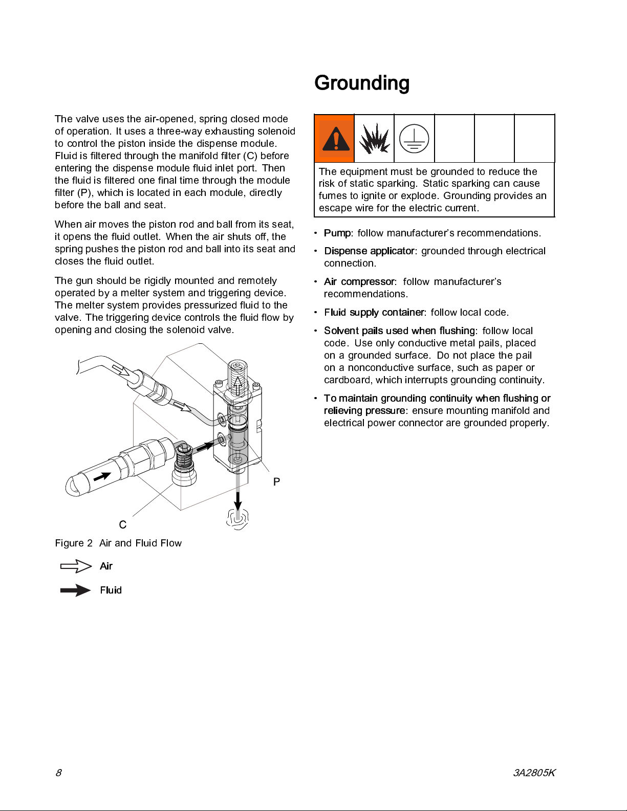
The valve uses the air-opened, spring closed mode
of operation. It uses a three-way exhausting solenoid
to control the piston inside the dispense module.
Fluid is filtered through the manifold filter (C) before
entering the dispense module fluid inlet port. Then
the fluid is filtered one final time t hrough the module
filter (P), which is located in each module, directly
before the ball and seat.
When air moves the piston rod and ball from its seat,
it opens the fluid outlet. When the air shuts off, the
spring pushes the piston rod and ball into its seat and
closes the fluid outlet.
The gun should be rigidly mounted and remotely
operated by a melter system and triggering device.
The melter system provides pressurized fluid to the
valve. The triggering device controls the fluid flow by
opening and closing the solenoid valve.
Grounding
The equipment must be grounded to reduce the
risk of static sparking. Static sparking can cause
fumes to ignite or explode. Grounding provides an
escape wire for the electric current.
•
Pump:
•
Dispense applicator:
connection.
•
Air compressor:
recommendations.
•
Fluid supply container:
•
Solvent pails used when flushing:
code. Use only conductive metal pails, placed
onagroundedsurface. Donotplacethepail
on a nonconductive surface, such as paper or
cardboard, which interrupts grounding continuity.
follow manufacturer’s recommendations.
grounded through electrical
follow manufacturer’s
follow local code.
follow local
Figure 2 Air and Fluid Flow
Air
Fluid
•
To maintain grounding continuity when flushing or
relieving pressure:
electrical power connector are grounded properly.
ensure mounting manifold and
8 3A2805K
Page 9
Installation
Installation
Mounting
NOTICE
To prevent heat transferring into other components
of the packaging line, ensure that the insulator (P)
is installed.
Low Profile Models:
adjust nuts that control position of gun assembly on
threaded rod.
All Other Models:
Mount manifold on a 1/2 in. (12 mm) diameter bar
using mounting clamp (H) to hold the gun assembly
in place and ensure adhesive is applied properly.
1. Use a 5 mm Allen wrench to loosen the mounting
clamp and slide the gun assembly on the
mounting bar.
2. Tighten the mounting clamp.
Note
Provide enough room to access sides of
applicator for maintenance and repair.
Usea3/4in.(19mm)wrenchto
See the following instructions.
2. Connect the cordset (M) to the hose.
3. Connect the hose inlet to the melter system
outlet. See the heated hose manual for
installation guidelines.
4. Connect the hose cordset to melter. See the
heated hose manual for installation guidelines.
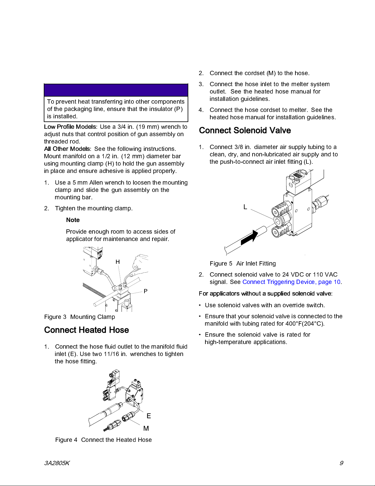
Connect Solenoid Valve
1. Connect 3/8 in. diameter air suppl y tubing to a
clean, dry, and non-lubricated air supply and to
the push-to-connect air inlet fitting (L).
Figure 3 Mounting Clamp
Connect Heated Hose
1. Connect the hose fluid outlet to the manifold fluid
inlet (E). Use two 11/16 in. wrenches to tighten
the hose fitting.
Figure 4 Connect the Heated Hose
Figure 5 Air Inlet Fitting
2. Connect solenoid valve to 24 VDC or 110 VAC
signal. See Connect Triggering Devi ce, page 10.
For applicators without a supplied solenoid valve:
• Use solenoid valves with an override switch.
• Ensure that your solenoid valve is connected to the
manifold with tubing rated for 400°F(204°C).
• Ensure the solenoid valve is rated for
high-temperature applications.
3A2805K 9
Page 10
Installation
Connect Triggering Device
Identify if your model uses a 24 VDC or 110 VAC
solenoid valve. Connect solenoid valve to 24 VDC
or 110 VAC signal.
Improper electrical connection can result in electric
shock. All electrical wiring must be done by a
qualified electrician and comply with all local codes
and regulations.
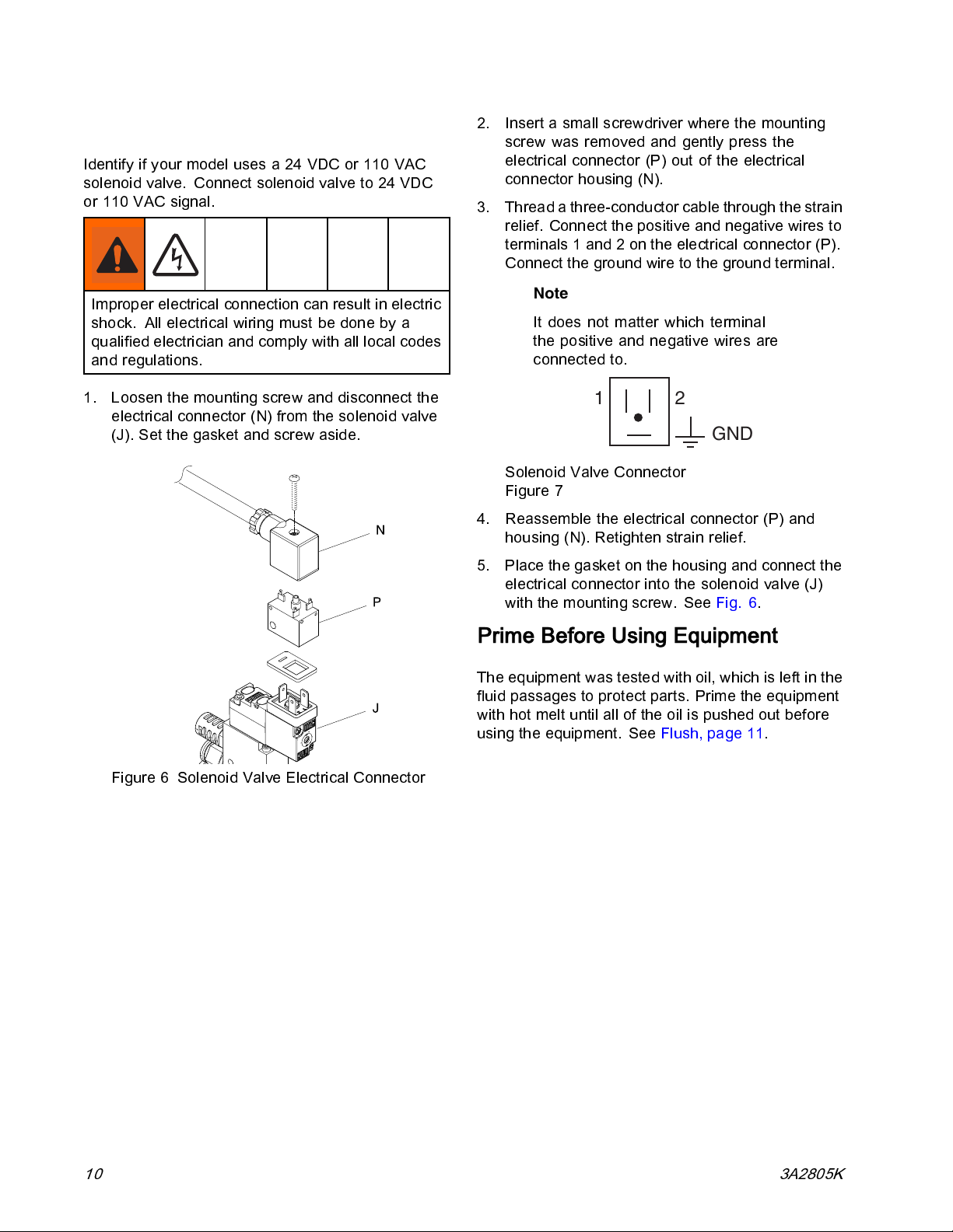
1. Loosen the mounting screw and disconnect the
electrical connector (N) from the solenoid valve
(J). Set the gasket and screw aside.
2. Insert a small screwdriver where the mounting
screw was removed and gently press the
electrical connector (P) out of the electrical
connector housing (N).
3. Thread a three-conductorcable through the strain
relief. Connect the positive and negative wires to
terminals 1 and 2 on the electrical connector (P).
Connect the ground wire to the ground terminal.
Note
It does not matter which terminal
the positive and negative wires are
connected to.
21
GND
Solenoid Valve Connector
Figure 7
4. Reassemble the electrical connector (P) and
housing (N). Retighten strain relief.
5. Place the gasket on the housing and connect the
electrical connector into the solenoid valve (J)
with the mounting screw. See Fig. 6.
Figure 6 Solenoid Valve Electrical Connector
Prime Before Using Equipment
The equipment was tested with oil, which is left in the
fluid passages to protect parts. Prime the equipment
with hot melt until all of the oil is pus hed out before
using the equipment. See Flush, page 11.
10 3A2805K
Page 11
Flush
1. Disconnect or turn off the device which triggers
the solenoid valve.
2. Heat the system to working temperature.
3. Place waste container under the gun to catch the
adhesive.
4. Ensure the nozzle is removed.
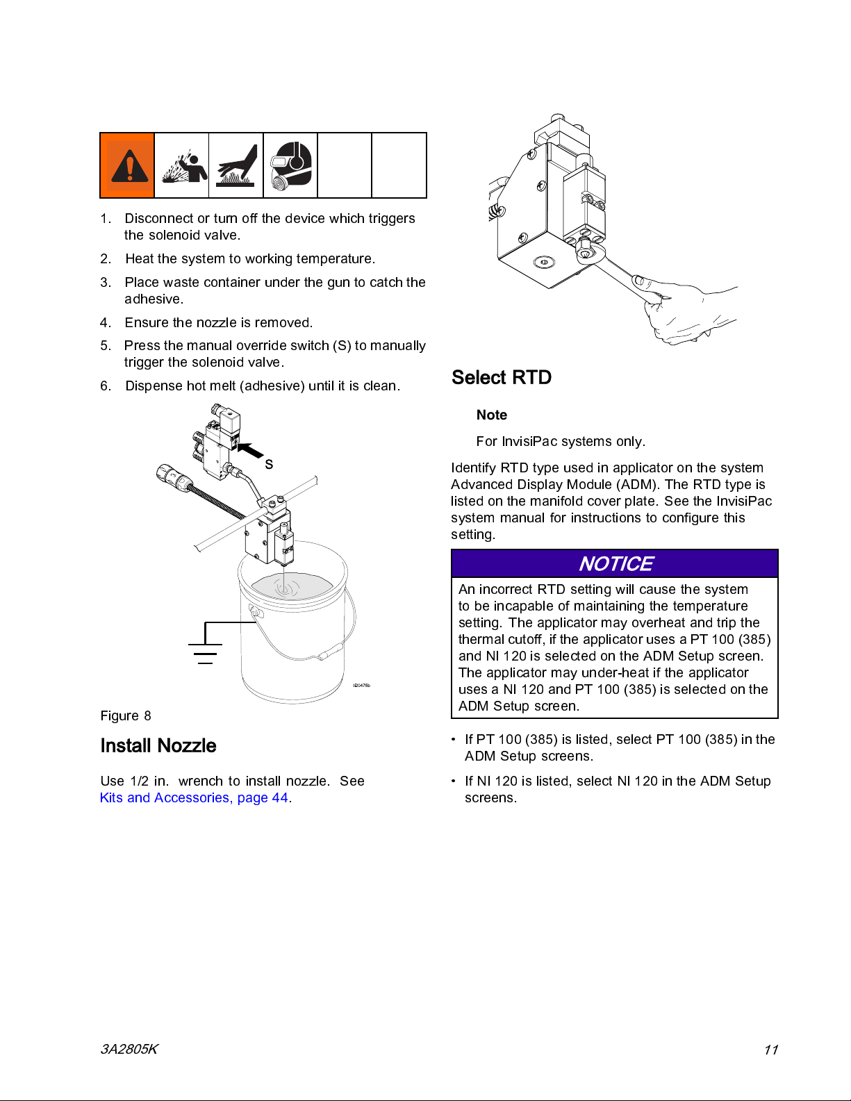
5. Press the manual override switch (S) to manually
trigger the solenoid valve.
6. Dispense hot melt (adhesive) until it is clean.
Installation
Select RTD
Note
For InvisiPac systems only.
Figure 8
Install Nozzle
Use 1/2 in. wrench to install nozzle. See
Kits and Accessories, page 44.
Identify RTD type used in applicator on the system
Advanced Display Module (ADM). The RTD type is
listed on the manifold cover plate. See the InvisiPac
system manual for instructions to configure this
setting.
NOTICE
An incorrect RTD setting will cause the system
to be incapable of maintaining the temperature
setting. The applicator may overheat and trip the
thermal cutoff, if the applicator uses a PT 100 (385)
and NI 120 is selected on the ADM Setup screen.
The applicator may under-heat if the applicator
uses a NI 120 and PT 100 (385) is selected on the
ADM Setup screen.
• If PT 100 (385) is listed, select PT 100 (385) in the
ADM Setup screens.
• If NI 120 is listed, select NI 120 in the ADM Setup
screens.
3A2805K
11
Page 12
Operation
Operation
Pressure Relief Procedure
Follow the Pressure Relief Procedure
whenever you see this symbol.
This equipment stays pressurized until pressure
is manually relieved. To help prevent serious
injury from pressurized fluid, such as skin injection,
and splashing fluid, follow the Pressure Relief
Procedure when you stop spraying and before
cleaning, checking, or servicing the equipment.
1. Depressurize system.
2. Close the bleed-type master air valve.
3. Actuate the applicator repeatedly until no fluid
flows.
Material inside the module and hose may still
be near setpoint temperature. Wear protective
clothing to avoid severe burns.
4. If you suspect the module nozzle is clogged,
remove nozzle and then actuate the module to
relieve pressure.
5. If you suspect the module or fluid hose is
clogged or that pressure has not been fully
relieved after following the steps above, VERY
SLOWLY loosen inlet fitting, inlet filter, or hose
end coupling to relieve pressure gradually,
then loosen completely. Clear hose or module
obstruction.
6. Turn off air pressure to the solenoid valve.
12
3A2805K
Page 13
Maintenance
Material inside the applicator can be near setpoint
temperature. Wear protective clothing to avoid
severe burns.
Daily:
Clean hot melt from exterior of gun.
Weekly:
Inspect the applicator, fluid lines, cordset,
and solenoid cable for wear or damage. See
Repair, page 19 for instructions.
Replace Inlet Filter
Maintenance
NOTICE
Remove the filter when the gun is hot. If the gun is
cold, the adhesive will be hard and the filter may
be difficult to remove or damaged.
1. Disable gun assembly. See
Before Beginning Repair, page 19.
Material inside the applicator can be near
setpoint temperature. Wear protective clothing
to avoid severe burns.
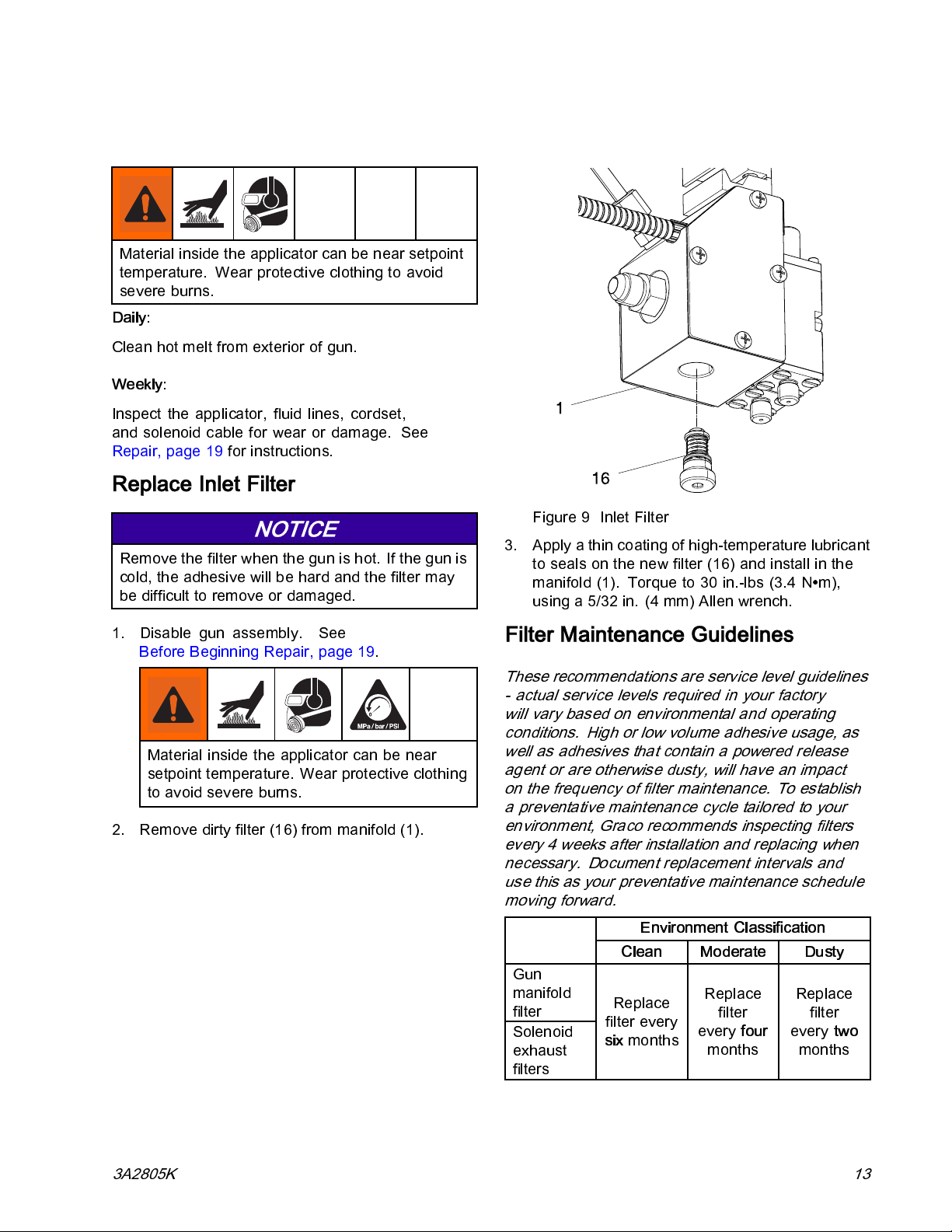
2. Remove dirty filter (16) from manifold (1).
Figure 9 Inlet Filter
3. Apply a thin coating of high-temperature lubricant
to seals on the new filter (16) and install in the
manifold (1). Torque to 30 in.-lbs (3.4 N∙m),
using a 5/32 in. (4 mm) Allen wrench.
Filter Maintenance Guidelines
These recommendations are service level guidelines
- actual service levels required in your factory
will vary based on environmental and operating
conditions. High or low volume adhesive usage, as
well as adhesives that contain a powered release
agent or are otherwise dusty, will have an impact
on the frequency of filter maintenance. To establish
a preventative maintenance cycle tailored to your
environment, Graco recommends inspecting filters
every 4 weeks after installation and replacing when
necessary. Document replacement intervals and
use this as your preventative maintenance schedule
moving forward.
Environment Classification
Moderate Dusty
Replace
filter
every
months
four
Replace
filter
every
months
two
Gun
manifold
filter
Solenoid
exhaust
filters
Clean
Replace
filter every
six
months
3A2805K 13
Page 14
Troubleshooting
Troubleshooting
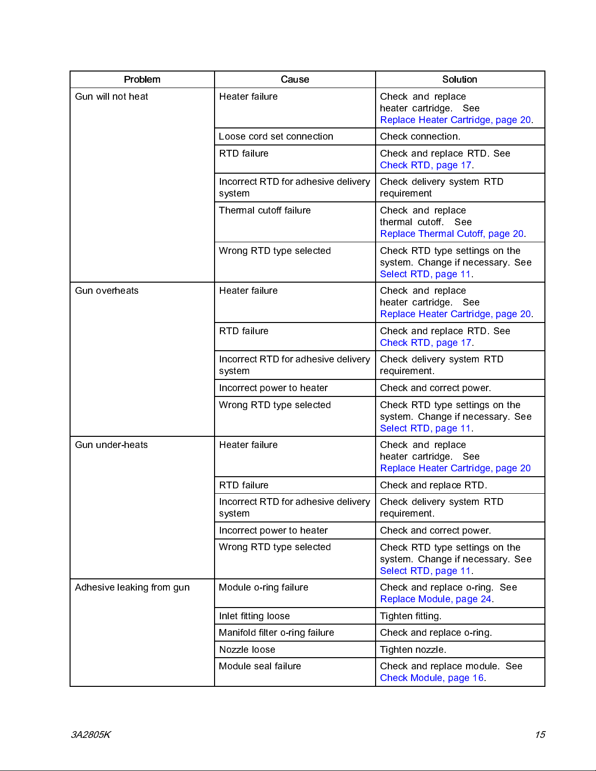
Problem Cause Solution
No adhesive or incorrect
amount of adhesive out of all
modules when triggered
Debris in manifold filter Replace manifold filter. See
Replace Inlet Filter, page 13.
Clogged hose Clean or replace hose.
Failed solenoid valve Check for correct operation. Clean
or replace.
No signal to solenoid valve
Incorrect solenoid valve wiring
Incorrect signal to solenoid valve
Solenoid muffler plugged Check and replace mufflers.
No fluid pressure Check adhesive delivery system.
Heater failure (cold gun) Check and replace
No air to solenoid valve
Dirty or faulty triggering device Check, clean, or replace triggering
Solenoid valve connected
incorrectly
Check solenoid valve for correct
operation.
Check solenoid valve wiring.
Check if 24 VDC or 120 VAC.
heater cartridges. See
Replace Heater Cartridge, page 20.
Check air supply.
device.
Check solenoid valve air connections.
No adhesive or incorrect
amount of adhesive out of
one/some modules when
triggered
Adhesive out of one/some
modules when not triggered
14
Clogged manifold passage Clean or replace manifold.
Debris in nozzle
Failed module in closed position Check for correct operation.
Debris in module filter Replace module. See
Clogged manifold passage Clean or replace manifold.
Failed module in open position
Adhesive pressure too high
Clean or replace nozzle.
Clean or replace. See
Check Module, page 16.
Replace Module, page 24.
Clean or replace module. See
Replace Module, page 24.
Check and reduce fluid pressure.
3A2805K
Page 15
Troubleshooting
Problem
Gun will not heat
Gun overheats
Cause Solution
Heater failure Check and replace
heater cartridge. See
Replace Heater Cartridge, page 20.
Loose cord set connection
RTD failure Check and replace RTD. See
Incorrect RTD for adhesive delivery
system
Thermal cutoff failure Check and replace
Wrong RTD type selected
Heater failure Check and replace
RTD failure Check and replace RTD. See
Incorrect RTD for adhesive delivery
system
Check connection.
Check RTD, page 17.
Check delivery system RTD
requirement
thermal cutoff. See
Replace Thermal Cutoff, page 20.
Check RTD type settings on the
system. Change if necessary. See
Select RTD, page 11.
heater cartridge. See
Replace Heater Cartridge, page 20.
Check RTD, page 17.
Check delivery system RTD
requirement.
Gun under-heats
Adhesive leaking from gun
Incorrect power to heater
Wrong RTD type selected Check RTD type settings on the
Heater failure Check and replace
RTD failure Check and replace RTD.
Incorrect RTD for adhesive delivery
system
Incorrect power to heater
Wrong RTD type selected
Module o-ring failure Check and replace o-ring. See
Inlet fitting loose Tighten fitting.
Manifold filter o-ring failure Check and replace o-ring.
Nozzle loose Tighten nozzle.
Module seal failure Check and replace module. See
Check and correct power.
system. Change if necessary. See
Select RTD, page 11.
heater cartridge. See
Replace Heater Cartridge, page 20
Check delivery system RTD
requirement.
Check and correct power.
Check RTD type settings on the
system. Change if necessary. See
Select RTD, page 11.
Replace Module, page 24.
Check Module, page 16.
3A2805K 15
Page 16
Troubleshooting
Problem
Adhesive out of all modules
when not triggered
Solenoid valve failure Check and replace solenoid valve.
Adhesive pressure too high
Solenoid valve connected
incorrectly
Module failure Check and replace all modules. See
Cause Solution
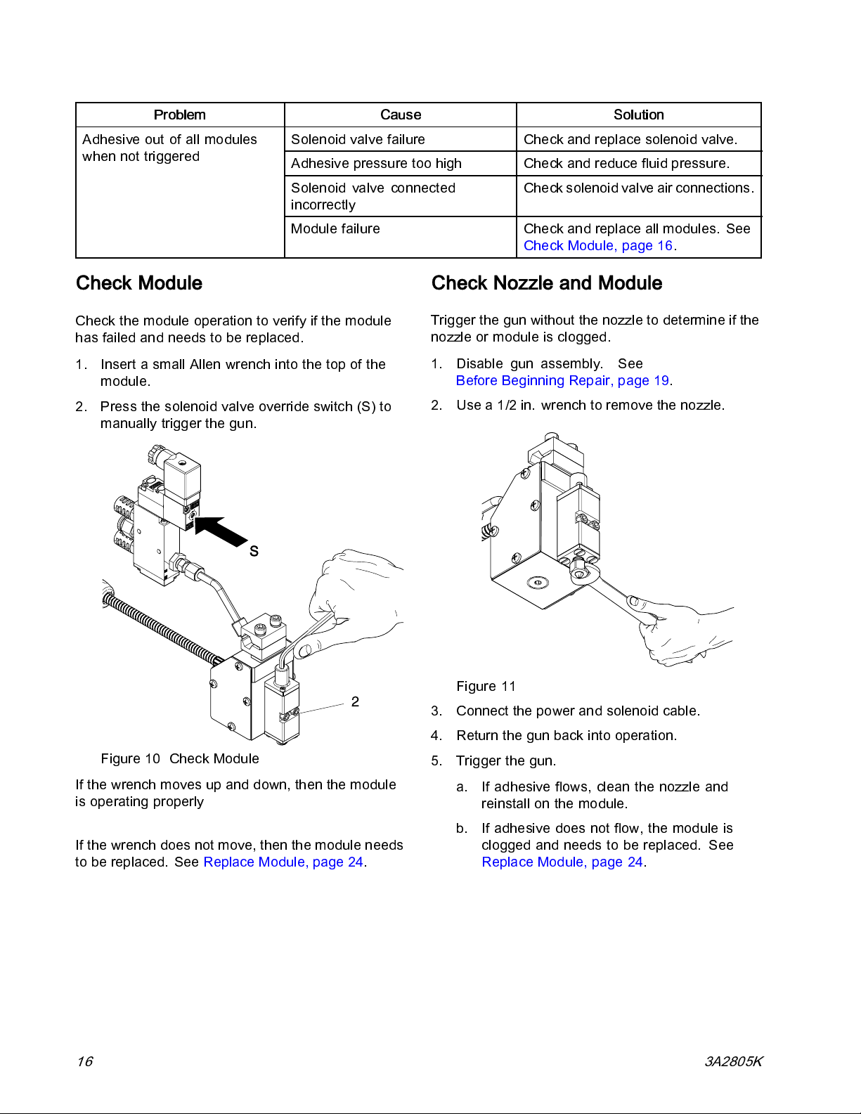
Check Module
Check the module operation to verify if the m odule
has failed and needs to be replaced.
1. InsertasmallAllenwrenchintothetopofthe
module.
2. Press the solenoid valve override switch (S ) to
manually trigger the gun.
Check and reduce fluid pressure.
Check solenoid valve air connections.
Check Module, page 16.
Check Nozzle and Module
Trigger the gun without the nozzle to determine if the
nozzle or module is clogged.
1. Disable gun assembly. See
Before Beginning Repair, page 19.
2. Usea1/2in.wrenchtoremovethenozzle.
Figure 11
3. Connect the power and solenoid cable.
4. Return the gun back into operation.
Figure 10 Check Module
If the wrench moves up and down, then the module
is operating properly
If the wrench does not move, then the module needs
to be replaced. See Repl ace Module, page 24.
16 3A2805K
5. Trigger the gun.
a. If adhesive flows, clean the nozzle and
reinstall on the mo dule.
b. If adhesive does not flow, the module is
clogged and needs to be replaced. See
Replace Module, page 24.
Page 17

Troubleshooting
Check Heater
Check the continuity of the heater to verify proper
resistance. If there is no continuity, the heater
may have failed and need to be replaced. See
Wiring Diagram, page 21, and parts illustrations.
1. Disable gun assembly. See
Before Beginning Repair, page 19.
2. Check resistance of the heater using a multimeter
between the pins of the cordset connector. See
connectors illustrations in cordset pin tables.
• If there is no continuity measure resistance of
the heater at the butt splice terminals (52b).
• If the resistance is outside the range listed
below replace the heater cartridge. See
Replace Heater Cartridge, page 20.
Cordset Check
Pins
24W087,
Pt 100
(385) RTD
Cordset
24W088,
Ni 120
RTD
Cordset
A and C
1 and 2
Gun Model Resis-
tance
Values
24U021–24U0
26
24U027–24U-
032
All other
models
24U021–24U0
26
24U027–24U-
032
All other
models
260–280
ohms
130–140
ohms
260–280
ohms
130–140
ohms
Table 1 24W087, Pt 100 (385) RTD Cordset
Pin Description
A
B
C
D
E
Table 2 24W088, Ni 120 RTD Cordset
Pin Description
1
2Heat-
3
5
G Ground
Thermal Cutoff
Ground
Heat -
RTD (White)
RTD (Red)
Thermal Cutoff
RTD (White)
RTD (Red)
Check RTD
Check the continuity of the RTD to verify proper
resistance. If there is no continuity, the RTD has
failed and needs to be replaced.
1. Disable gun assembly. See
Before Beginning Repair, page 19.
2. Check resistance of the RTD using a multimeter
between the pins of the cordset connector. See
connectors illustrations in cordset pin tables.
Cordset Check Pins
Resistance
Values
At Room
Temperature
70–72°F
(21–22°C)
3A2805K
24W087, Pt
100 (385)
RTD Cordset
24W088, Ni
120 RTD
Cordset
3. Replace the RTD if the resistance reading is
outside the range, or if there is no continuity. See
Replace RTD, page 20.
D and E 107-115
ohms
3 and 5 130-140
ohms
17
Page 18

Troubleshooting
Check Thermal Cutoff
If working properly, the cutoff will trip at 450°F
(232°C) and resets at 370°F (187°C). If failure is
suspected, allow gun to cool and then check the
continuity of the thermal cutoff to verify it has not
failed. If there is no continuity, the cutoff has failed
andneedstobereplaced.
1. Disable gun assembly. See
Before Beginning Repair, page 19.
2. Remove cover plate.
3. Check for continuity using a multimeter between
pin of cordset connector and the wires from the
thermal cutoff that connects to the heater lead.
Cordset Check Pins
24W087, Pt 100 (385)
RTD Cordset
A
Thermal Cutoff
WLD
24W088, Ni 120 RTD
Cordset
1
18 3A2805K
Page 19

Repair
Required Tools
• Phillips screw driver
•Flatbladescrewdriver
• 5/64in(2mm)and5/32in.(4mm)Allenwrenches
• 1/2 in. and 7/16 in. wrenches
• Torque wrench
• Waste container
• High-temperature anaerobic thread sealant (110110)
• High-temperature lubricant (24T156)
• Anti-sieze (24T179)
• Crimp tool (24W086)
Repair
Before Beginning Repair
1. Turn off the melter system. See melter manual
for shutdown instructions.
2. Relieve pressure. See
Pressure Relief Procedure, page 12.
3. Disconnect the cordset from the heated hose.
4. Loosen the mounting screw and disconnect the
solenoid valve power connector (N) from the
solenoid valve (J).
Figure 13 Disconnect Solenoid Valve Power
Connector
Figure 12 Disconnect Cordset
3A2805K 19
Page 20
Repair
Replace Heater Cartridge
1. Disable gun assembly.
2. Use a Phillips screwdriver to remove screws (15)
and manifold cover plate (52).
3. Remove the heater cartridges (3) from the
manifold (1).
Note
Note the placement of the heaters and
lead lengths.
Note
On guns that are not low profile,
heater cartridge does not easily pull out,
remove the other cover plate (18) and
press out with a small screwdriver.
4. Remove butt splices(52b ) from heater wires (3),
thermal cutoff (52a), and cordset wire leads (17).
5. Recrimp new heater wires into new splices (52b).
See wiring diagram.
if the
NOTICE
To prevent a short to ground and bl owing a
MZLP fuse, ensure bare wires are covered
with fiberglass tape and sleeves (52c) are
centered over splices (52b).
6. Insert the new heater cartridges (3) into the
manifold (1), placing the heater with the shorter
leads closer to the wiring port.
Note
Do not apply thermal grease to the
heater cartridge.
7. Reinstall the manifold cover plate (52).
8. Reconnect the cordset (17) to the heated hose.
9. Reconnect the solenoid valve power connector
to the solenoid valve (9).
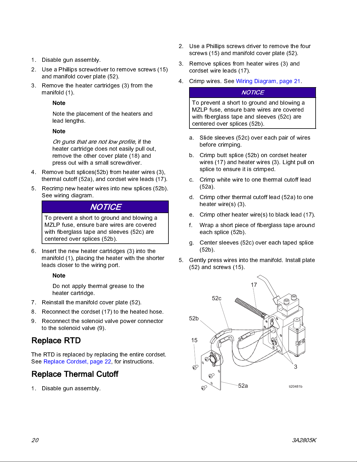
2. Use a Phillips screws driver to remove the four
screws (15) and manifold cover plate (52).
3. Remove splices from heater wires (3) and
cordset wire leads (17).
4. Crimp wires. See Wiring Diagram, page 21.
NOTICE
To prevent a short to ground and blowing a
MZLP fuse, ensure bare wires are covered
with fiberglass tape and sleeves (52c) are
centered over splices (52b).
a. Slide sleeves (52c) over each pair of wires
before crimping.
b. Crimp butt splice (52b) on cordset heater
wires (17) and heater wires (3). Light pull on
splice to ensure it is crimped.
c. Crimp white wire to one thermal cutoff lead
(52a).
d. Crimp other thermal cutoff lead (52a) to one
heater wire(s) (3).
e. Crimp other heater wire(s) to black lead (17).
f. Wrap a short piece of fiberglass tape around
each splice (52b).
g. Center sleeves (52c) over each taped splice
(52b).
5. Gently press wires into the manifold. Install plate
(52) and screws (15).
F
E
Replace RTD
The RTD is replaced by replacing the entire cordset.
See Replace Cordset, page 22, for instructions.
Replace Thermal Cutoff
1. Disable gun assembly.
20 3A2805K
D
WLE
Page 21

Wiring Diagram
Thermal Cutoff
Repair
17
17
52b
52b
52a
52b
33
Note
Slim (24U021–24U026) and Low Profile Dual (24U026–24U032) applicators use one heater (3).
3A2805K
21
Page 22

Repair
Replace Cordset
See Fig 14, page 24.
Note
There are two types of cordsets (17):
24W087 is for PT100 (385) RTD controlled
guns and 24W088 is for NI 120 Ohm
RTD controlled guns. Ensure you have
the correct cordset before replacing. See
Parts, page 26.
1. Disable gun assembly. See
Before Beginning Repair, page 19.
2. Use a Phillips screwdriver to remove the four
screws (15) and manifold cover plate (52).
3. Usea2mmAllenwrenchtoremovetheset
screw (8) holding the cordset (17) on the manifold
(1).
4. Use a Phillips screwdriver to remove the ground
screw (15) and star washer (20) from the
manifold (1).
5. Remove the RTD (R) from the manifold (1).
Note
On guns that are not low profile,
RTD does not easily pull out, remove the
other cover plate (19) and press out with
a small screwdriver.
6. Disconnect thermal cutoff (52).
7. Remove the cordset (17) from the manifold (1).
8. Install the new cordset, RTD, and ground (17 in
the manifold (1). Recrimp thermal cutoff wires.
See Wiring Diagram, page 21, for connections.
Note
Ensure the cordset bushing is fully
inserted into the manifold.
9. Install set screw (8) against the cordset bushing
to secure the cordset (17) to the manifold (1).
if the
22
3A2805K
Page 23

Repair
10. Reinstall the ground lead onto the manifold (1).
Note
Ensure the star washer (20) is placed
below the ground ring terminal.
11. Insert the plug (P), RTD (R) and thermal cutoff
(52) into the manifold ports. See Fig 14.
Note
Do not apply grease on the RTD or
thermal cutoff.
12. Insert the heater cartridges (3) in the manifold (1).
NOTICE
To prevent removing wire insulation or
disconnecting wires, do not pinch any wires
when inserting wire in the manifold. If wire
insulation is removed, the RTD or heaters
could short out and need to be replaced.
13. Reinstall the manifold cover plate (52).
14. Reconnect the cordset (17) to the heated hose.
15. Return to service.
Figure 14 Repair Parts
3A2805K 23
NOTE:
of the Parts chapter ( Parts, page 26).
See Slim and Low Profile GS35 subsections
Page 24

Repair
Replace Solenoid Valve
1. Disable gun assembly. See
Before Beginning Repair, page 19.
2. Remove solenoid valve fitting (102) and solenoid
valve (9) from tube (7).
3. Use a 1/2 in. and 7/16 in. wrench to tighten new
connector (102) to tube (7).
Figure 15 Replace Solenoid Valve
Replace Module
NOTICE
Do not allow adhesive to enter the air ports,
to allow air to flow through valve. Adhesive in
the air ports will obstruct the flow of air and
damage the valve.
Figure 16 Remove Module From Manifold
3. Apply high temperature lubricant to o-rings in
module (2).
4. Apply anti-seize to two screw threads (22). Use
a5/32in. (4mm)Allenwrenchtoinstallnew
module(2)onmanifoldwithtwoscrews(22).
Torque to 28–32 in.-lbs (3.2–3.6 N•m).
1. Disable gun assembly. See
Before Beginning Repair, page 19.
Material inside the applicator can be near
setpoint temperature. Wear protective clothing
to avoid severe burns.
2. Use a 5/32 in. (4 mm) Allen wrench to remove
the two mounting screws (22) and module (2)
from manifold (1).
5. Connect cordset (17) to the heated hose.
Replace Applicator
Material inside the applicator can be near setpoint
temperature. Wear protective clothing to avoid
severe burns.
1. Disable gun assembly. See
Before Beginning Repair, page 19.
2. Loosen the mounting bar clamp and remove the
applicator from the mounting bar.
3. Install new applicator. See Installat ion, page 9 .
24
3A2805K
Page 25

Notes
Notes
3A2805K 25
Page 26

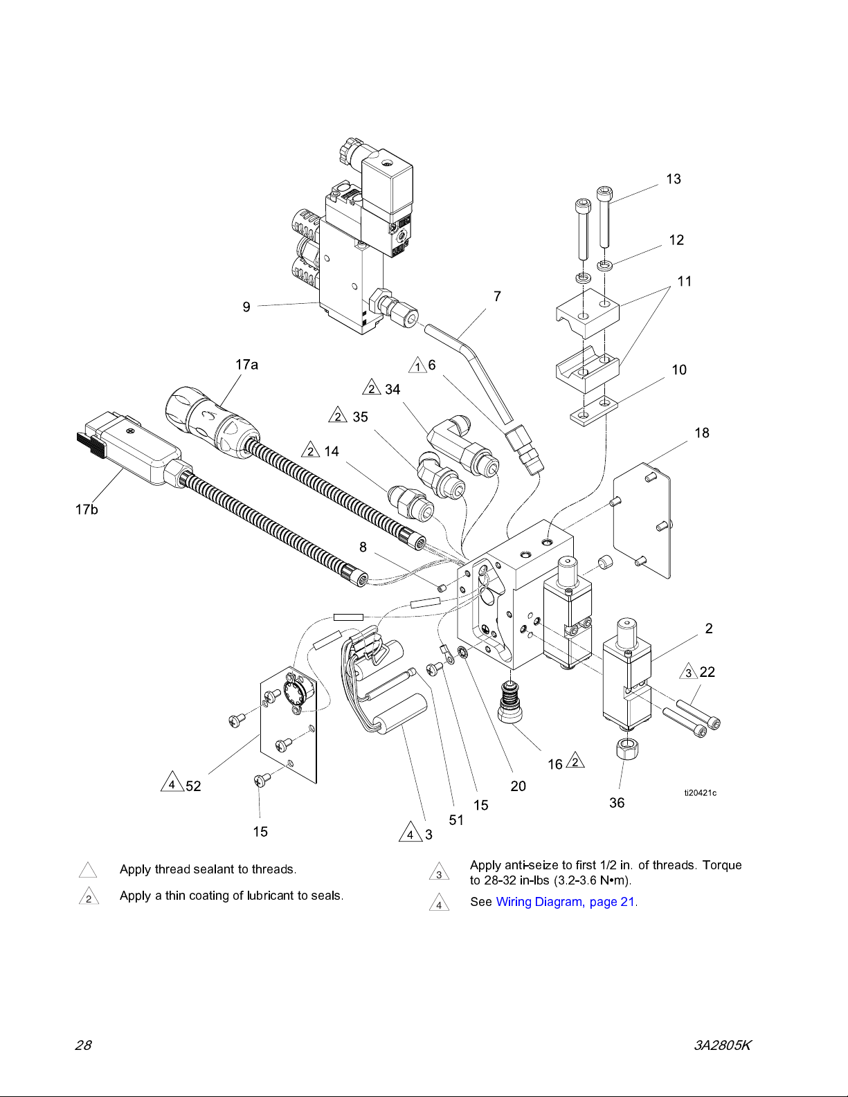
Parts
Parts
Single GS35
ply anti-seize to first 1/2 in. of threads. Torque
Apply thread sealant to threads.
1
Apply a thin coating of lubricant to seals.
2
Ap
3
4
28-32 in-lbs (3.2-3.6 N∙m).
to
See Wiring Diagram, page 21.
26 3A2805K
Page 27
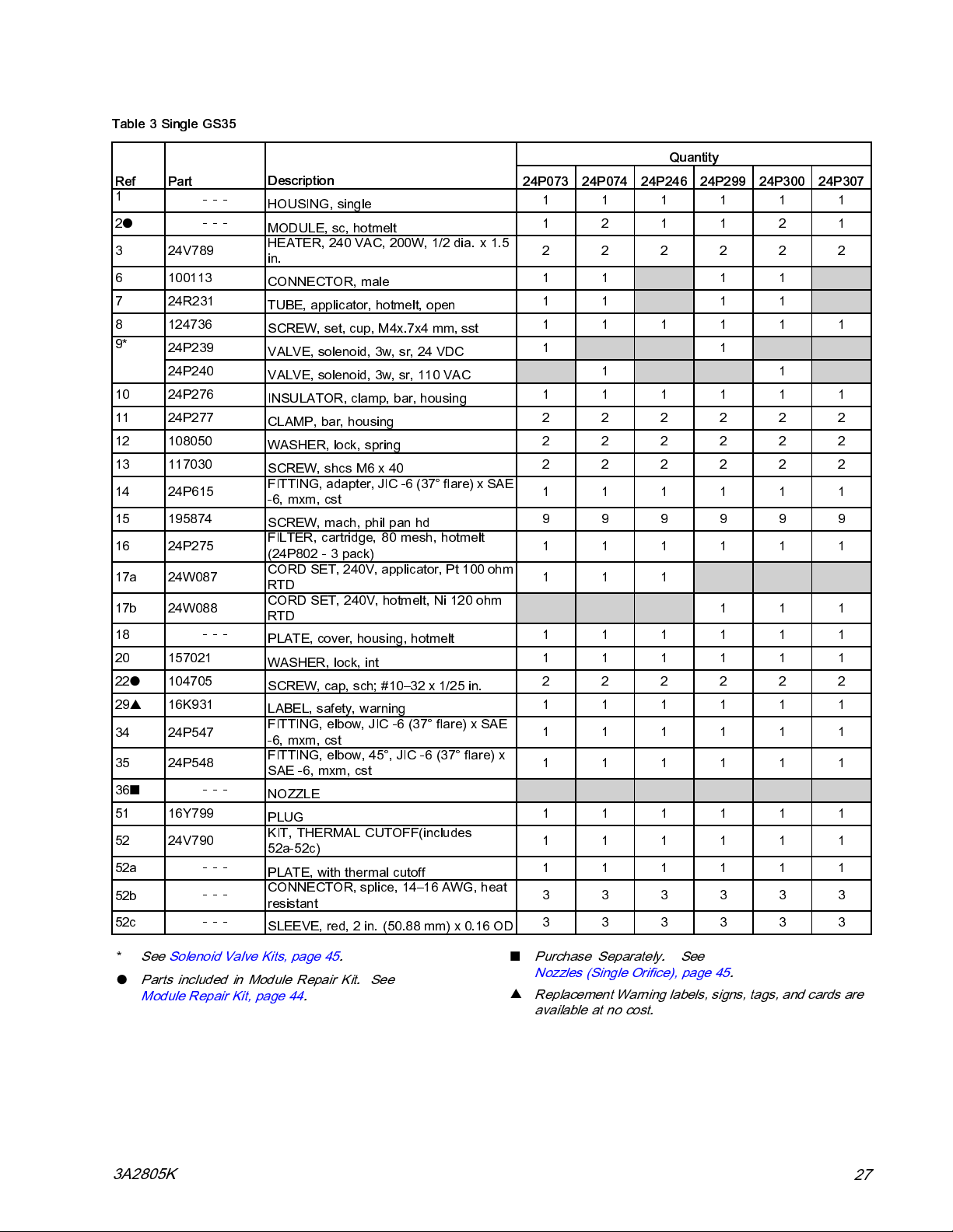
Table3SingleGS35
Ref Part
1
2
●
3 24V789
6 100113
7 24R231
8 124736
9*
10 24P276
11 24P277
12 108050
13 117030
14 24P615
15 195874
16 24P275
17a 24W087
17b 24W088
18
20 157021
22
●
29
▲
34 24P547
35 24P548
36
■
51 16Y799
52 24V790
52a
52b
52c
---
---
24P239
24P240
---
104705
16K931
---
---
---
---
Description
HOUSING, single
MODULE, sc, hotmelt
HEATER, 240 VAC, 200W, 1/2 dia. x 1.5
in.
CONNECTOR, male
TUBE, applicator, hotmelt, open
SCREW, set, cup, M4x.7x4 mm, sst
VALVE, solenoid, 3w, sr, 24 VDC
VALVE, solenoid, 3w, sr, 110 VAC
INSULATOR, clamp, bar, housing
CLAMP, bar, housing
WASHER, lock, spring
SCREW, shcs M6 x 40
FITTING, adapter, JIC -6 (37° flare) x SAE
-6, mxm, cst
SCREW, mach, phil pan hd
FILTER,
(24P802
CORD SET, 24 0V, applicator, Pt 100 ohm
RTD
CORD SET, 240V, hotmelt, Ni 120 ohm
RTD
PLATE, cover, housing, hotmelt
WASHER, lock, int
SCREW, cap, sch; #10–32 x 1/25 in.
LABEL, safety, warning
FITT
-6,
FITTING, elbow, 45°, JIC -6 (37° flare) x
SAE -6, mxm, cst
NOZZLE
PLUG
KIT, THERMAL CUTOFF(includes
52a-52c)
PLATE, with thermal cutoff
C
resistant
SLEEVE, red, 2 in. (50.88 mm) x 0.16 OD
cartridge, 80 mesh, hotmelt
- 3 pack)
ING, elbow, JIC -6 (37° flare) x SAE
mxm, cst
ONNECTOR, splice, 14–16 AWG, heat
Parts
Quantity
24P073 24P074 24P246 24P299 24P300 24P307
111111
121121
222222
11 11
11 11
111111
11
11
111111
222222
222222
222222
111111
999999
111111
111
111
111111
111111
222222
111111
111111
111111
111111
111111
111111
333333
333333
*
See Solenoid Valve Kits, page 45.
●
Parts included in Module Repair Kit. See
Module Repair Kit, page 44.
3A2805K
■
Purchase Separately. See
Nozzles (Single Orifice), page 45.
▲
Replacement Warning labels, signs, tags, and cards are
available at no cost.
27
Page 28
Parts
DUAL GS35
Apply thread sealant to threads.
1
Apply a thin coating of lubricant to seals.
2
Apply anti-seize to first 1/2 in. of threads. Torque
3
to 28-32 in-lbs (3.2-3.6 N∙m).
See Wiring Diagram, page 21.
4
28 3A2805K
Page 29

Table 4 Dual GS35
Parts
Ref Part
1
2
●
324V789
6 100113
724R231
8 124736
9*
10 24P276
11 24P277
12 108050
13 117030
14 24P615
15 195874
16 24P275
17a 24W087
17b 24W088
18
20 157021
22
●
29
▲
34 24P547
35 24P548
36
■
51 16Y799
52 24V790
52a
52b
52c
---
---
24P239
24P240
---
104705
16K931
---
---
---
---
Description
HOUSING, dual
MODULE, sc, hotmelt
HEATER, 240 VAC, 200W, 1/2 dia. x
1.5 in.
CONNECTOR, male
TUBE, applicator, hotmelt, open
SCREW, set, cup, M4 x .7 x 4 mm, sst
VALVE, solenoid, 3w, sr, 24 VDC
VALVE, solenoid, 3w, sr, 110 VAC
INSULATOR, clamp, bar, housing
CLAMP, bar, housing
WASHER, lock, spring
SCREW, shcs M6 x 40
FITTING, adapter, JIC -6 (37° flare) x
SAE -6, mxm, cst
SCREW, mach, phil pan hd
FILTER,
(24P802
CORD SET, 240V, applicator, Pt 100
ohm RTD
CORD SET, 240V, hotmelt, Ni 120 ohm
RTD
PLATE, cover, housing, hotmelt
WASHER, lock, int
SCREW, cap, sch; #10–32 x 1/25 in.
LABEL, safety, warning
FITT
SAE
FITTING, elbow, 45°, JIC -6 (37° flare)
x SAE -6, mxm, cst
NOZZLE
PLUG
KIT, THERMAL CUTOFF (includes
52a-52c)
PLATE, with thermal cutoff
C
heat resistant
SLEEVE, red, 2 in. (50.88 mm) x 0.16
OD
cartridge, 80 mesh, hotmelt
-3pack)
ING, elbow, JIC -6 (37° flare) x
-6, mxm, cst
ONNECTOR, splice, 14–16 AWG,
24P075 24P076 24P247 24P301 24P302 24P308
111111
222222
222222
11 11
11 11
111111
11
11
111111
222222
222222
222222
111111
999999
111111
111
111
111111
111111
444444
111111
111111
111111
111111
111111
111111
333333
333333
*
See Solenoid Valve Kits, page 45.
●
Parts included in Module Repair Kit. See
Module Repair Kit, page 44.
■
Purchase Separately. See
Nozzles (Single Orifice), page 45.
▲
Replacement Warning labels, signs, tags, and cards are
available at no cost.
3A2805K 29
Page 30

Parts
Quad GS35
24P077 Type I Shown
Apply thread sealant to threads.
1
Apply a thin coating of lubricant to seals.
2
Apply anti-seize to first 1/2 in. of threads. Torque
3
to 28-32 in-lbs (3.2-3.6 N∙m)).
See Wiring Diagram, page 21.
4
30 3A2805K
Page 31
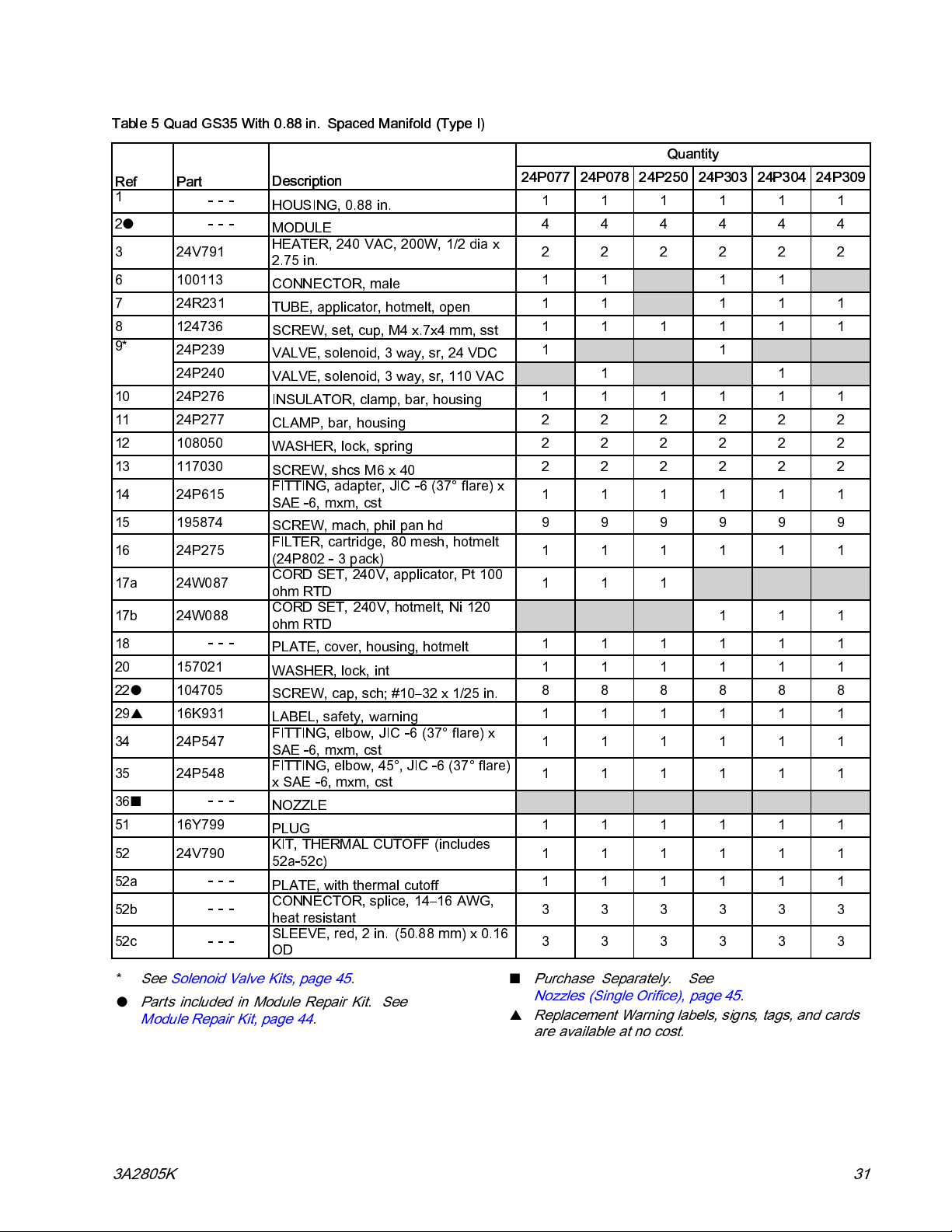
Table 5 Quad GS35 With 0.88 in. Spaced Manifold (Type I)
Ref Part
1
2
●
3 24V791
6 100113
7
8 124736
9*
10 24P276
11 24P277
12 108050
13 117030
14 24P615
15 195874
16 24P275
17a 24W087
17b 24W088
18
20 157021
22
●
29
▲
34 24P547
35 24P548
36
■
51 16Y799
52 24V790
52a
52b
52c
---
---
24R231
24P239
24P240
---
104705
16K931
---
---
---
---
Description
HOUSING, 0.88 in.
MODULE
HEATER, 240 VAC, 200W, 1/2 dia x
2.75 in.
CONNECTOR, male
TUBE, applicator, hotmelt, open
SCREW, set, cup, M4 x.7x4 mm, sst
VALVE, solenoid, 3 way, sr, 24 VDC
VALVE, solenoid, 3 way, sr, 110 VAC
INSULATOR, clamp, bar, housing
CLAMP, bar, housing
WASHER, lock, spring
SCREW, shcs M6 x 40
FITTING, adapter, JIC -6 (37° flare) x
SAE -6, mxm, cst
SCREW, mach, phil pan hd
FILTER, cartridge, 80 mesh, hotmelt
(24P802-3pack)
CORD SET, 240V, applicator, Pt 100
ohm RTD
CORD SET, 240V, hotmelt, Ni 120
ohm RTD
PLATE, cover, housing, hotmelt
WASHER, lock, int
SCREW, cap, sch; #10–32 x 1/25 in.
LABEL, safety, warning
FITTING, elbow, JIC -6 (37° flare) x
SAE -6, mxm, cst
FITTING, elbow, 45°, JIC -6 (37° flare)
x SAE -6, mxm, cst
NOZZLE
PLUG
KIT, THERMAL CUTOFF (includes
52a-52c)
PLATE, with thermal cutoff
CONNECTOR, splice, 14–16 AWG,
heat resistant
SLEEVE, red, 2 in. (50.88 mm) x 0.16
OD
Parts
Quantity
24P077 24P078 24P250 24P303 24P304 24P309
111111
444444
222222
11 11
11 111
111111
11
11
111111
222222
222222
222222
111111
999999
111111
111
111
111111
111111
888888
111111
111111
111111
111111
111111
111111
333333
333333
*
See Solenoid Valve Kits, page 45.
●
Parts included in Module Repair Kit. See
Module Repair Kit, page 44.
■
Purchase Separately. See
Nozzles (Single Orifice), page 45.
▲
Replacement Warning labels, signs, tags, and cards
are available at no cost.
3A2805K 31
Page 32

Parts
Table 6 Quad GS35 with 1.5 in. Spaced Manifold (Type II)
Ref Part
1
2
●
3 24V791
6 100113
7
8 124736
9*
10 24P276
11 24P277
12 108050
13 117030
14 24P615
15 195874
16 24P275
17a 24W087
17b 24W088
18
20 157021
22●104705
29▲16K931
34 24P547
35 24P548
36
51 16Y799
52 24V790
52a
52b
52c
---
---
24R231
24P239
24P240
---
■
---
---
---
Description
HOUSING, 1.5 in.
MODULE
HEATER, 240 VAC, 200W, 1/2 dia x
2.75 in.
CONNECTOR, male
TUBE, applicator, hotmelt, open
SCREW, set, cup, m4 x.7x4 mm, sst
VALVE, solenoid, 3 way, sr, 24 VDC
VALVE, solenoid, 3 way, sr, 110
VAC
INSULATOR, clamp, bar, housing
CLAMP, bar, housing
WASHER, lock, spring
SCREW, shcs M6 x 40
FITTING, adapter, JIC -6 (37° flare)
x SAE -6, mxm, cst
SCREW, mach, phil pan hd
FILTER, cartridge, 80 mesh, hotmelt
(24P802-3pack)
CORD SET, 240V, applicator, Pt 100
ohm RTD
CORD SET, 240V, hotmelt, Ni 120
ohm RTD
PLATE, cover, housing, hotmelt
WASHER, lock, int
SCREW,
LABEL, safety, warning
FITTING, elbow, JIC -6 (37° flare) x
SAE -6, mxm, cst
FITTING, elbow, 45°, JIC -6 (37°
flare) x SAE -6, mxm, cst
NOZZLE
PLUG
KIT, THERMAL CUTOFF (includes
52a-52c)
PLATE, with thermal cutoff
CONNECTOR, splice, 14–16 AWG,
heat resistant
SLEEVE, red, 2 in. (50.88 mm) x
0.16 OD
cap, sch; #10–32 x 1/25 in.
24P079 24P080 24P254 24P305 24P306 24P310
Quantity
11 1111
44 4444
22 2222
11 11
11 11
11 1111
11
11
11 1111
22 2222
22 2222
22 2222
11 1111
99 9999
11 1111
111
11 1
11 1111
11 1111
88 8888
11 1111
11 1111
11 1111
11 1111
11 1111
11 1111
33 3333
33 3333
*
See Solenoid Valve Kits, page 45.
●
Parts included in Module Repair Kit. See
Module Repair Kit, page 44.
■
Purchase Separately. See
Nozzles (Single Orifice), page 45.
▲
Replacement Warning labels, signs, tags, and cards
are available at no cost.
32 3A2805K
Page 33

Notes
Parts
3A2805K 33
Page 34

Parts
Slim GS35
Apply thread sealant to threads.
1
Apply a thin coating of lubricant to seals.
2
Apply anti-seize to first 1/2 in. of threads. Torque
3
to 28-32 in-lbs (3.2-3.6 N∙m)).
See Wiring Diagram, page 21.
4
34 3A2805K
Page 35

Parts
Table7SlimGS35
Quantity
Ref Part
---
1
---
2
●
324V793HEATER,240VAC,200W,1/2diax1.5in.111111
6 100113 CONNECTOR, male 1 1 1 1
7
16P769 TUBE, applicator, hotmelt, open 1 1 1 1
8124736SCREW,set,cup,M4x0.7x4mm,sst111111
24P239 VALVE, solenoid, 3 way, sr, 24 VDC 1 19*
24P240 VALVE, solenoid, 3 way, sr, 120 VAC 1 1
1024P276INSULATOR,clamp,bar,housing 111111
1124P277CLAMP,bar,housing 222222
12108050WASHER,lock,spring 222222
13 117030
14 24P615
15 195874
16 24P275
17a 24W087
24W088 CORD SET, 240V, hotmelt, Ni 120 ohm
17b
---
18
20157021WASHER,lock,int 111111
22●104705SCREW,cap,sch 222222
3424P547FITTING,elbow,JIC06xSAE06,mm,cs111111
35 24P548 FITTING, elbow, 45, JIC06 x SAE06, mm,
---
36
■
42 16W708PLAT
Description
HOUSING,slim 111111
MODULE 111111
SCREW, shcs M6 x 40
FITTING, adapter, JIC 06 x SAE 06, mm,
cs
SCREW, mach, phil pan hd
FILTER, gun, 80 mesh (3–pack: 24P802)
CORD SET, 240V, applicator, Pt 100 ohm
RTD
RTD
PLATE,cover,side,slim 111111
c
NOZZLE (not shown)
E, cover, bottom, slim
24U021 24U022 24U023 24U024 24U025 24U026
222222
111111
11 11 11 11 11 11
111111
111
111
111111
111111
51 16Y799
52 24V792
52a
52b
52c
*
●
--
---
---
e Solenoid Valve Kits, page 45.
Se
arts included in Module Repair Kit. See
P
odule Repair Kit, page 44.
M
PLUG
KIT, THERMAL CUTOFF (includes
52a-52c)
-
PLATE, with thermal cutoff
CONNECTOR, splice, 14–16 AWG, heat
resistant
SLEEVE, red, 2 in. (50.88 mm) x 0.16 OD
111111
111111
111111
333333
333333
■
urchase Separately. See
P
ozzles (Single Orifice), page 45.
N
▲
Replacement Warning labels, signs, tags, and cards are
available at no cost.
3A2805K 35
Page 36

Parts
Low Profile Dual GS35
Apply thread sealant to threads.
1
Apply a thin coating of lubricant to seals.
2
Apply anti-seize to first 1/2 in. of threads. Torque
3
to 28-32 in-lbs (3.2-3.6 N∙m)).
See Wiring Diagram, page 21.
4
36 3A2805K
Page 37

Table 8 Low Profile Dual GS35
Ref Part
1
2
3 24V793
6 100113
7
8 124736
9*
10 24P276
---
---
●
16P769 TUBE, applicator, hotmelt, open 1 1 1 1
24P239
24P240
Description
HOUSING, double
MODULE, sc
HEATER, 240 VAC, 200W, 1/2 dia x 1.5 in.
CONNECTOR, male
SCREW, set, cup, M4 x 0.7 x 4 mm, sst
VALVE, solenoid, 3 way, sr, 24 VDC
VALVE, solenoid, 3 way, sr, 120 VAC
INSULATOR, clamp, bar, housing
Parts
Quantity
24U027 24U028 24U029 24U030 24U031 24U032
111111
222222
111111
11 11
111111
11
11
111111
11
12 108050 WASHER, lock, spring 2 2 2 2 2 2
13 117029 SCREW, shcs, M6 x 25 2 2 2 2 2 2
14 24P615 FITTING, adapter, JIC06 x SAE06, mm, cs 1 1 1 1 1 1
15 195874 SCREW, mach, phil pan hd
16 24P275 FILTER, gun, 80 mesh (3–pack: 24P802) 1 1 1 1 1 1
17a 24W087 CORD SET, 240V, applicator, Pt 100 ohm
17b 24W088 CORD SET, 240V, hotmelt, Ni 120 ohm
18
20 157021 WASHER, lock, int 1 1 1 1 1 1
21 103147 PLUG, pipe 3 3 3 3 3 3
22
34 24P547 FITTING, elbow, JIC06 x SAE06, mm, cs 1 1 1 1 1 1
35 24P548 FITTING, elbow, 45, JIC06 x SAE06, mm, c 1 1 1 1 1 1
36
42 16W70
44 24U69
45
46
47
48
49
50 1005
---
---
●
104705 SCREW, cap, sch 4 4 4 4 4 4
---
■
10259
10002
1095
1000
---
70
18
08
BLOCK 111111
555555
111
RTD
111
RTD
PLATE, s
NOZZLE (not shown)
9
PLATE
8
ROD, mtg, threaded 1 1 1 1 1 1
8
SCREW, cap, socket head 1 1 1 1 1 1
0
WASHER, lock 1 1 1 1 1 1
WASHER, plain 2 2 2 2 2 2
WASHER, lock, spring 2 2 2 2 2 2
NUT,
SCREW, drive 4 4 4 4 4 4
ide
, cover, end
1/2-13 hex
111111
111111
222222
51 16Y799
PLUG
111111
3A2805K 37
Page 38
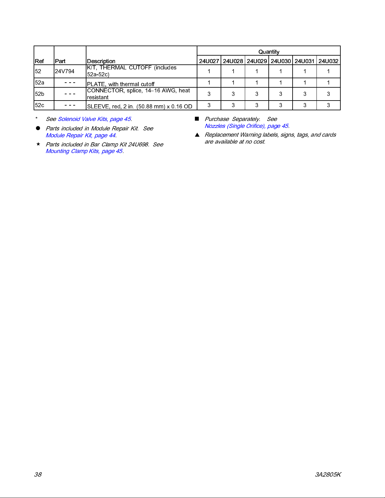
Parts
Ref Part
52 24V794
52a
52b
52c
---
---
---
Description
KIT, THERMAL CUTOFF (includes
52a-52c)
PLATE, with thermal cutoff
CONNECTOR, sp
resistant
SLEEVE, red, 2 in. (50.88 mm) x 0.16 OD
lice, 14–16 AWG, heat
Quantity
24U027 24U028 24U029 24U030 24U031 24 U032
111111
111111
333333
333333
*
See Solenoid Valve Kits, page 45.
●
Parts included in Module Repair Kit. See
Module Repair Kit, page 44.
Parts included in Bar Clamp Kit 24U698. See
Mounting Clamp Kits, page 45.
■
Purchase Separately. See
Nozzles (Single Orifice), page 45.
▲
Replacement Warning labels, signs, tags, and cards
are available at no cost.
38 3A2805K
Page 39

Notes
Parts
3A2805K 39
Page 40

Parts
Low Profile Quad GS35
Apply thread sealant to threads.
1
Apply a thin coating of lubricant to seals.
2
Apply anti-seize to first 1/2 in. of threads. Torque
3
to 28-32 in-lbs (3.2-3.6 N∙m)).
See Wiring Diagram, page 21.
4
40 3A2805K
Page 41

Table 9 Low Profile Quad GS35
Ref Part
1
2
●
3
6
7
8
9*
10
11
12
13
14
15
16
17a 24W087
17b 24W088
18
20
21
22
●
34
35
36
■
38
▲
39
42
44
45
46
47
48
49
50
51
---
---
24V795
100113
16P769 TUBE, applicator, hotmelt, open
124736
126407 VALVE, solenoid, 3 way, sr, 24
126408 VALVE, solenoid, 3 way, sr, 120
16P848
---
108050
117029
126544
195874
24P275
---
157021
103147
104705
126748
126749
---
16K931
103473
16V721 PLATE, cover, applicator
24U698
102598
100020
109570
100018
-
--
100508
16Y799
Description
HOUSING, quad
MODULE, sc, invisipac
HEATER, 240 VAC, 200W, 1/2
dia x 1.5 in.
CONNECTOR, male
SCREW, set, cup, M4x 0.7 x 4
mm, sst
VDC
VAC
INSULATOR, clamp, bar, housing
BLOCK, mtg
WASHER, lock, spring
SCREW, shcs M6 x 25
FITTING, adapter, JIC06 x
SAE06, mm, cs
SCREW, mach, phil pan hd
FILTER, gun, 80 mesh (3-pack:
24P802)
CORD SET, 240V, applicator, Pt
100 ohm RTD
CORD SET, 240V, hotmelt, Ni
120 ohm RTD
PLATE, side, quad
WASHER, lock, int
PLUG, pipe
SCREW, cap, sch
FITTING, elbow, JIC06 x SAE06,
mm, cs
FITTING, elbow, 45, JIC06 x
SAE06, mm, c
NOZZLE (not shown)
TAG, warning, turbo
STRAP, tie, wire
ROD, mtg, threaded
SCREW, cap, socket head
WASHER, lock
WASHER, plain
WASHER, lock, spring
NUT, 1/2-13 hex
SCREW, drive
PLUG
Parts
Quantity
24U033 24U034 24U035 24U036 24U037 24U038
111111
444444
222222
11 11
11 11
111111
11
11
111111
111111
222222
222222
111111
666666
111111
111
111
111111
111111
333333
888888
111111
111111
111111
111111
111111
111111
111111
111111
222222
222222
222222
222222
111111
3A2805K
41
Page 42

Parts
Ref Part
52
52a
52b
52c
24V796 KIT, THERMAL CUTOFF
---
---
---
Description
(includes 52a-52c)
PLATE, with th
CONNECTOR, sp
AWG, heat res
SLEEVE, red, 2 in. (50.88 mm)
x0.16OD
ermal cutoff
lice, 14–16
istant
Quantity
24U033 24U034 24U035 24U036 24U037 24U038
111111
111111
333333
333333
*
See Solenoid
●
Parts includ
Module Repai
Parts included in Bar Clamp Kit 24U698. See
Mounting Clamp Kits, page 45.
Valve Kits, page 45.
ed in Module Repair Kit. See
r Kit, page 44.
■
Purchase Sep
Nozzles (Si
▲
Replacement Warning labels, signs, tags, and cards
are available at no cost.
arately. See
ngle Orifice), page 45.
42
3A2805K
Page 43
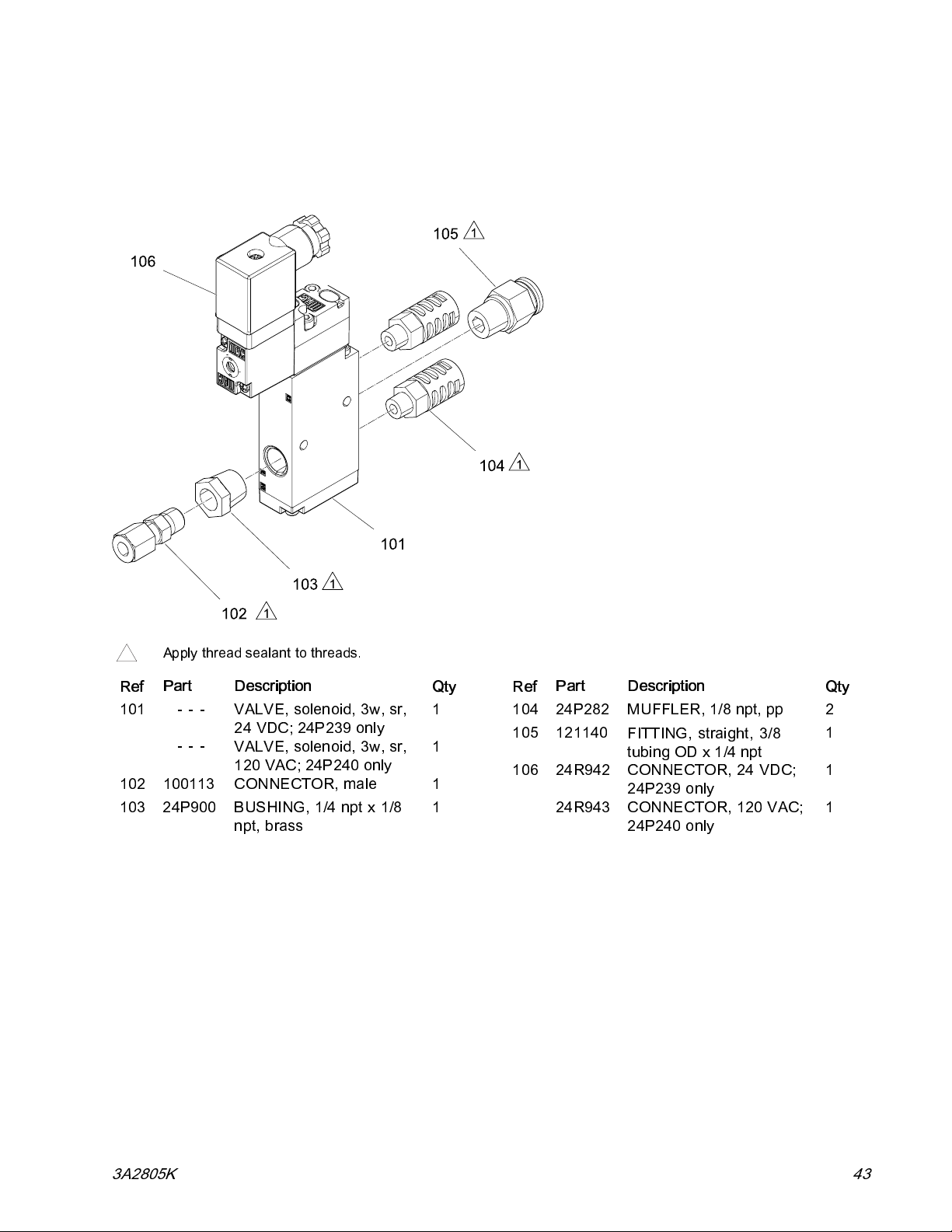
Solenoid Valve Kits
24P239, 24 VDC Solenoid Valve 24P240, 110 VAC Solenoid Valve
Parts
Apply thread sealant to threads.
1
Part Description
Ref
101
102 100113 CONNECTOR, male 1
103 24P900 BUSHING, 1/4 npt x 1/8
---
---
VALVE, solenoid, 3w, sr,
24 VDC; 24P239 only
VALVE, solenoid, 3w, sr,
120 VAC; 24P240 only
npt, brass
Qty
1
1
1
Part Description
Ref
104 24P282 MUFFLER, 1/8 npt, pp 2
105 121140
106 24R942
24R943
FITTING, straight, 3/8
tubing OD x 1/4 npt
CONNECTOR, 24 VDC;
24P239 only
CONNECTOR, 120 V AC;
24P240 only
Qty
1
1
1
3A2805K 43
Page 44
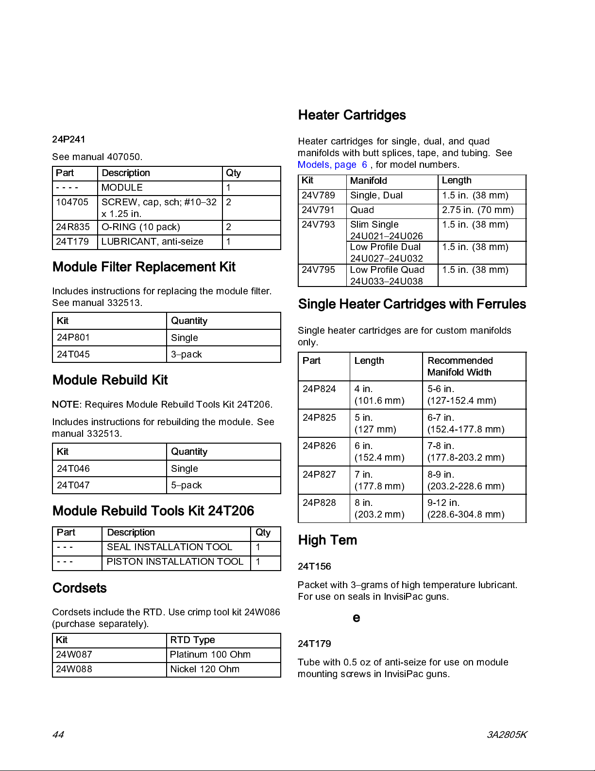
Kits and Accessories
Kits and Accessories
Module Replacement
24P241
See manual 407050.
Part Description
----
104705
24R835
24T179
MODULE
SCREW, cap, sch; #10–32
x1.25in.
O-RING (10 pack )
LUBRICANT, anti-seize
Qty
1
2
2
1
Module Filter Replacement Kit
Includes instructions for replacing the modul e filter.
See manual 332513.
Kit
24P801
24T045 3–pack
Quantity
Single
Module Rebuild Kit
NOTE:
Includes instructions for rebuilding the module. See
manual 332513.
Requires Module Rebuild Tools Kit 24T206.
Kit
24T046 Single
24T047 5–pack
Quantity
Heater Cartridges
Heater cartridges for single, dual, and quad
manifolds with butt splices, tape, and tubing. See
Models, page 6 , for model numbers.
Kit
24V789
24V791
24V793
24V795
Manifold
Single, Dual 1.5 in. (38 mm)
Quad 2.75 in. (70 mm)
Slim Single
24U021–24U026
Low Profile Dual
24U027–24U032
Low Profile Quad
24U033–24U038
Length
1.5in.(38mm)
1.5in.(38mm)
1.5in.(38mm)
Single Heater Cartridges with Ferrules
Single heater cartridges are for custom manifolds
only.
Part Length Recommended
Manifold Width
24P824 4 in.
(101.6 mm)
24P825 5 in.
(127 mm)
24P826 6 in.
(152.4 mm)
24P827 7 in.
(177.8 mm)
5-6 in.
(127-152.4 mm)
6-7 in.
(152.4-177.8 mm)
7-8 in.
(177.8-203.2 mm)
8-9 in.
(203.2-228.6 mm)
Module Rebuild Tools Kit 24T206
Part Description Qty
---
---
SEAL INSTA LLA TIO N TOOL 1
PISTON INSTALLATION TOOL 1
Cordsets
Cordsets include the RTD. Use crimp tool kit 24W086
(purchase separately).
Kit RTD Type
24W087 Platinum 100 Ohm
24W088 N icke l 120 Ohm
44
24P828 8 in.
(203.2 mm)
9-12 in.
(228.6-304.8 mm)
High Temperature Lubricant
24T156
Packet with 3–grams of high temperature lubricant.
For use on seals in InvisiPac guns.
Anti-Seize
24T179
Tubewith0.5ozofanti-seizeforuseonmodule
mounting screws in InvisiPac guns.
3A2805K
Page 45

Kits and Accessories
Mufflers
24P282
Includes two mufflers that can be used with solenoid
valve kits.
Blanking Plate Kit
24P810
Use to run two or three modules on a quad applicator
or one module on a dual applicator. See manual
407051.
Solenoid Valve and Fitting Kits
3–Way (air open - spring close) Solenoid Valves
Kit Description
24P239
24P240
24 VDC
110 VAC
Inlet Filter
Kit
24P275
24P802 3 Pack
Qty
Single
Material Inlet Fittings
Mounting Clamp Kits
See Models, page 6 , for model numbe rs.
24P277 (Single, Dual, and Quad GS35)
Part Description
Ref
10 24P276
11
12 108050
13 117030
24U698 (Low Profile GS35, 24U027–24U038))
Ref
10 24P276
11
12 108050
13 117029
44
45
46
47
48
49
---
Part Description
---
---
---
---
---
---
---
INSULATOR, clamp, bar,
housing
CLAMP, bar housing
WASHER, lock, spring
SCREW, shcs, M6 x 40
INSULATOR, clamp, bar,
housing
BLOCK, mating, low
profile
WASHER, lock, spring
SCREW, shcs, M6 x 25
ROD
SCREW, cap, socket head
WASHER, lock
WASHER, plain
WASHER, lock, spring
NUT, 1/2–13 2
Qty
1
2
2
2
Qty
1
1
2
2
1
1
1
2
2
Single Kit
24P615
24P548
24P547
Thermal Cutoff Replaceme
For Series A and Series B Models.
Kit Models Description
24V790 See Models,
page 6
24V792 24U021-
24U026
24V794 24U027-
24U032
24V796 24U033-
24U038
Description
Straight
45°
90°
nt Kits
Standard
Slim Single
Dual Low
Profile
Quad Low
Profile
Nozzles (Single Orifice)
Single
24P636 24P794 0.008 straight
24P637 24P795 0.010 straight
24P638 24P796 0.012 straight
24P639 24P797 0.016 straight
24P640 24P798 0.018 straight
24P641 24P799 0.020 straight
24P642 24P800 0.024 straight
24P643 24P803
24P644 24P804
24P645 24P805
24P646 24P806
24P647 24P807
24P648 24P808
24P649 24P809
5 Pack Description
0.008 90°
0.010 90°
0.012 90°
0.016 90°
0.018 90°
0.020 90°
0.024 90°
3A2805K 45
Page 46

Dimensions
Dimensions
Single, Dual, and Quad GS35
24P075 Shown
0.79 in.
(20.0 mm)
24P077 Type I Shown
0.72 in.
(18.16 mm)
9.3 in. (236.2 mm)
7.93 in. (201.42 mm)
5.01 in.
(127.25 mm)
1.00 in.
(25.4 mm)
1.14 in.
(28.96 mm)
3.07 in.
(77.98 mm)
3.94 in.
(100.1 mm)
24P079 Type II Shown
3.63 in.
(92.2 mm)
0.5 in.
(12.7 mm)
4.24 in.
(107.7 mm)
0.31 in.
(7.9 mm)
0.625 in.
(15.8 mm)
A
A
A
C
B
Applicator A
in. (mm)
Single 2.23 (56.6)
Dual 0.88 (22.4) 2.23 (56.6)
Quad - Type I 0.88 (22.4) 3.74 (95) 0.88 (22.4)
Quad - Type II 0.88 (22.4) 4.36 (111) 1.5 (38)
See Models, page 6 , for applicator model numbers.
46 3A2805K
C
B
B
in. (mm)
A
0.25 in.
(6.25 mm)
C
in. (mm)
Page 47

Slim GS35
(24U021-24U026)
24U021 Shown
0.79 in.
(20.0 mm)
Dimensions
11.68 in.
(296.67 mm)
0.67 in.
(17.02 mm)
1.35 in. (34.29 mm)
5.01 in.
(127.25 mm)
4.24 in.
(107.70 mm)
3.63 in.
(92.20 mm)
1.0 in.
(25.4 mm)
2.41 in.
(61.21 mm)
2.86 in.
(72.64 mm)
3.16 in.
(80.26 mm)
4.04 in.
(102.62 mm)
3A2805K
47
Page 48

Dimensions
Low Profile Double GS35
(24U027-24U033)
24U027 Shown
0.88 in.
(22.35 mm)
1.94 in.
(49.28 mm)
0.79 in.
(20.1 mm)
1.0 in.
(25.4 mm)
6.29 in.
(159.77 mm)
11.69 in.
(296.93 mm)
1.5 in.
(38.1 mm)
0.13 in.
(3.30 mm)
5.66 in.
(143.76 mm)
3.18 in.
(80.77 mm)
2.30 in.
(58.42 mm)
48 3A2805K
Page 49

Low Profile Quad GS35
(24Ubob 033-24U038)
24U033 Shown
Dimensions
0.88 in.
(22.35 mm)
(92.20 mm)
(22.35 mm)
3.63 in.
0.88 in.
0.79 in.
(20.1 mm)
0.88 in.
(22.35 mm)
6.29 in.
(159.77 mm)
1.0 in.
(25.4 mm)
11.69 in.
(296.93 mm)
1.5 in.
(38.1 mm)
0.13 in.
(3.30 mm)
5.16 in.
(131.06 mm)
3.18 in.
(80.77 mm)
2.30 in.
(58.42 mm)
3A2805K 49
Page 50

Technical D ata
Technical Data
InvisiPac™GS35 Plug-Free Hot Melt Adhesive Applicator
US Metric
Speed
Heat up Time
Electrical Service
Maximum Working Fluid Pressure 1500 psi 10.3 MPa, 103 bar
Maximum Air Pressure 80 psi 0.5 MPa, 5.5 bar
Minimum Air Pressure 40 psi 0.3 MPa, 2.7 bar
Maximum O p erati ng Temperature 400°F 204°C
Ambient Storage Temperature
Range
Ambient Operating Temperature
Range
Solenoid Air Flow Rating 1.0 Cv
Wetted Parts Aluminum, carbon steel, stainless steel, carbide, brass,
Cordsets
24W087
24W088 Ni 120 RTD
Solenoid Control Voltages
< 10 minutes to 350°F at 240 VAC < 10 minutes to 176°C at 240 VAC
32-122°F 0-50°C
32-122°F 0-50°C
> 3,500 cycles/minute
200-240V, 50–60 Hz, 400W
chemically resistant seals, chrome
Pt 100 (385) RTD
24P239
24P240
Noise
Sound pressure measured 6.5 ft
(2m) from gun at 80 psi (550kPa,
5.5 bar)
24 VDC
110 VAC
75.6 dB(A)
50 3A2805K
Page 51

Notes
Notes
3A2805K 51
Page 52

Graco Extended Warranty
Graco warrants all equipment referenced in this document whic h is manufactured by Graco and bearing its
name to be free from defects in material and workmanship on the date of sale to the original purchaser for use.
With the exception of any special, extended, or limited warranty published by Graco, Graco will, for a period of
eighteen months from the date of sale, repair or replace any part of the equipment determined by Graco to be
defective. This warranty applies only when the equipment is installed, operated and maintained in accordance
with Graco’s written recommendations.
This warranty does not cover, and Graco shall not be liable for general wear and tear, or any malfunction,
damage or wear caused by faulty installation, misapplication, abrasion, corrosion, inadequate or improper
maintenance, negligence, accident, tampering, or substitution of non-Graco component parts. Nor shall Graco
be liable for malfunction, damage or wear caused by the incompatibility of Graco equipment with structures,
accessories, equipment or materials not supplied by Graco, or the improper design, manufacture, installation,
operation or maintenance of structures, accessories, equipment or materials not supplied by Graco.
This warranty is conditioned upon the prepaid return of the equipment claimed to be defective to an authorized
Graco distributor for verification of the claimed defect. If the claimed defect is verified, Graco will repair or replace
free of charge any defective parts. The equipment will be returned to the original purchaser transportation
prepaid. If inspection of the equipment does not disclose any defect in material or workmanship, repairs will be
made at a reasonable charge, which charges may include the costs of parts, labor, and transportation.
THIS WARRANTY IS EXCLUSIVE, AND IS IN LIEU OF ANY OTHER WARRANTIES, EXPRESS OR IMPLIED,
INCLUDING BUT NOT LIMITED TO WARRANTY OF MERCHANTABILITY OR WARRANTY OF FITNESS
FOR A PARTICULAR PURPOSE.
Graco’s sole obligation and buyer’s sole remedy for any breach of warranty shall be as set forth above. The
buyer agrees that no other remedy (including, but not limited to, incidental or consequential damages for lost
profits, lost sales, injury to person or property, or any other incidental or consequential loss) shall be available.
Any action for breach of warranty must be brought within two (2) years of the date of sale.
GRACO MAKES NO WARRANTY, AND DISCLAIMS ALL IMPLIED WARRANTIES OF MERCHANTABILITY
AND FITNESS FOR A PARTICULAR PURPOSE, IN CONNECTION WITH ACCESSORIES, EQUIPMENT,
MATERIALS OR COMPONENTS SOLD BUT NOT MANUFACTURED BY GRACO.
manufactured by Graco (such as electric motors, switches, hose, etc.), are subject to the warranty, if any, of
their manufacturer. Graco will provide purchaser with reasonable assistance in making any claim for breach of
these warranties.
In no event will Graco be liable for indirect, incidental, special or consequential damages resulting from Graco
supplying equipment hereunder, or the furnishing, performance, or use of any products or other goods sold
hereto, whether due to a breach of contract, breach of warranty, the negligence of Graco, or otherwise.
FOR GRACO CANADA CUSTOMERS
The Parties acknowledge that they have required that the present document, as well as all documents, notices
and legal proceedings entered into, given or instituted pursuant hereto or relating directly or indirectly hereto, be
drawn up in English. Les parties reconnaissent avoir conv enu que la rédaction du présente document sera en
Anglais, ainsi que tous documents, avis et procédures judiciaires exécutés, donnés ou intentés, à la suite de ou
en rapport, directement ou indirectement, avec les procédures concernées.
These items sold, but not
Graco Information
For more information about InvisiPac, visit www.InvisiPac.com or email InvisiPac@graco.com.
To place an order,
For technical assistance or customer service, call toll free: 1–800–458–2133.
All written and vis ual data contained in this document reflects the latest product information available at the time of publication.
GRACO INC. AND SUBSIDIARIES • P.O. BOX 1441 • MINNEAPOLIS MN 55440-1441 • USA
contact your Graco Distributor or call to identify the nearest distributor.
Graco reserves the right to make changes at any time without notice.
For patent information, see www.graco.com/patents.
Original Instructions. This manual contains English. MM 3A2805
Graco Headquarters:
International Offices:
Copyright 2012, Graco Inc. All Graco manufacturing locations are registered to ISO 9001.
Belgium, China, Japan, Korea
www.graco.com
Revised August 2014
Minneapolis
 Loading...