

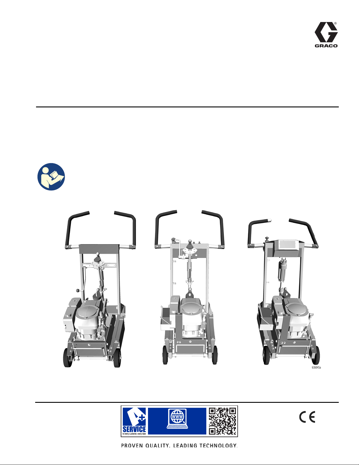
Graco GrindLazer Pro RC813 G, GrindLazer Pro Series, GrindLazer Pro RC813 G DCS, 25N669, 25M847 Operation, Repair, And Parts
www.graco.com/techsupport
?? ??
Operation, Repair, Parts
25M847
25M847 (Series B)
25N669
™
GrindLazer
For removal of materials from flat horizontal concrete and asphalt surfaces. For
professional use only.
Pro Series - Rotary Cut
Model 25M847 - GrindLazer Pro RC813 G (390 cc / 13hp Electric Start)
Model 25M847 - GrindLazer Pro RC813 G (390 cc / 13hp Electric Start) (Series B)
Model 25N669 - GrindLazer Pro RC813 G DCS (390 cc / 13hp Electric Start)
Important Safety Instructions
Read all warnings and instructions in this manual before using the
equipment. Be familiar with the controls and the proper usage of the
equipment. Save these instructions.
3A5581C
EN

Contents
Contents
Warnings . . . . . . . . . . . . . . . . . . . . . . . . . . . . . . . . . . . . . . . . . . . . . . . . . . . . . . . . . . . . . . . . . . . . . . . . . . . . . . . . . . . . . . . . . 3
Battery Disposal . . . . . . . . . . . . . . . . . . . . . . . . . . . . . . . . . . . . . . . . . . . . . . . . . . . . . . . . . . . . . . . . . . . . . . . . . . . . . . . . 4
Component Identification . . . . . . . . . . . . . . . . . . . . . . . . . . . . . . . . . . . . . . . . . . . . . . . . . . . . . . . . . . . . . . . . . . . . . . . . . . . 5
25M847 . . . . . . . . . . . . . . . . . . . . . . . . . . . . . . . . . . . . . . . . . . . . . . . . . . . . . . . . . . . . . . . . . . . . . . . . . . . . . . . . . . . . . . . 5
Component Identification . . . . . . . . . . . . . . . . . . . . . . . . . . . . . . . . . . . . . . . . . . . . . . . . . . . . . . . . . . . . . . . . . . . . . . . . . . . 6
25M847 (Series B) . . . . . . . . . . . . . . . . . . . . . . . . . . . . . . . . . . . . . . . . . . . . . . . . . . . . . . . . . . . . . . . . . . . . . . . . . . . . . . 6
Component Identification . . . . . . . . . . . . . . . . . . . . . . . . . . . . . . . . . . . . . . . . . . . . . . . . . . . . . . . . . . . . . . . . . . . . . . . . . . . 7
25N669 . . . . . . . . . . . . . . . . . . . . . . . . . . . . . . . . . . . . . . . . . . . . . . . . . . . . . . . . . . . . . . . . . . . . . . . . . . . . . . . . . . . . . . . 7
Setup . . . . . . . . . . . . . . . . . . . . . . . . . . . . . . . . . . . . . . . . . . . . . . . . . . . . . . . . . . . . . . . . . . . . . . . . . . . . . . . . . . . . . . . . . . . . 8
Handle Bar Adjustment . . . . . . . . . . . . . . . . . . . . . . . . . . . . . . . . . . . . . . . . . . . . . . . . . . . . . . . . . . . . . . . . . . . . . . . . . . . 8
Engine Kill Button . . . . . . . . . . . . . . . . . . . . . . . . . . . . . . . . . . . . . . . . . . . . . . . . . . . . . . . . . . . . . . . . . . . . . . . . . . . . . . . 8
Cutter Head Installation/Replacement . . . . . . . . . . . . . . . . . . . . . . . . . . . . . . . . . . . . . . . . . . . . . . . . . . . . . . . . . . . . . . . 8
Dust Control . . . . . . . . . . . . . . . . . . . . . . . . . . . . . . . . . . . . . . . . . . . . . . . . . . . . . . . . . . . . . . . . . . . . . . . . . . . . . . . . . . 11
DCS Control (DCS Models only) . . . . . . . . . . . . . . . . . . . . . . . . . . . . . . . . . . . . . . . . . . . . . . . . . . . . . . . . . . . . . . . . . . . 12
Operation . . . . . . . . . . . . . . . . . . . . . . . . . . . . . . . . . . . . . . . . . . . . . . . . . . . . . . . . . . . . . . . . . . . . . . . . . . . . . . . . . . . . . . . 16
Machine Start Up . . . . . . . . . . . . . . . . . . . . . . . . . . . . . . . . . . . . . . . . . . . . . . . . . . . . . . . . . . . . . . . . . . . . . . . . . . . . . . 16
Cutting Material . . . . . . . . . . . . . . . . . . . . . . . . . . . . . . . . . . . . . . . . . . . . . . . . . . . . . . . . . . . . . . . . . . . . . . . . . . . . . . . . 17
Stop Cutting Material . . . . . . . . . . . . . . . . . . . . . . . . . . . . . . . . . . . . . . . . . . . . . . . . . . . . . . . . . . . . . . . . . . . . . . . . . . . 20
DCS Instructions . . . . . . . . . . . . . . . . . . . . . . . . . . . . . . . . . . . . . . . . . . . . . . . . . . . . . . . . . . . . . . . . . . . . . . . . . . . . . . . 21
Maintenance . . . . . . . . . . . . . . . . . . . . . . . . . . . . . . . . . . . . . . . . . . . . . . . . . . . . . . . . . . . . . . . . . . . . . . . . . . . . . . . . . . . . . 23
DCS Control Translations (DCS Models only) . . . . . . . . . . . . . . . . . . . . . . . . . . . . . . . . . . . . . . . . . . . . . . . . . . . . . . . . . . 24
Repair . . . . . . . . . . . . . . . . . . . . . . . . . . . . . . . . . . . . . . . . . . . . . . . . . . . . . . . . . . . . . . . . . . . . . . . . . . . . . . . . . . . . . . . . . . 26
Belt Replacement and Adjustment . . . . . . . . . . . . . . . . . . . . . . . . . . . . . . . . . . . . . . . . . . . . . . . . . . . . . . . . . . . . . . . . . 26
Drive Pulley Replacement . . . . . . . . . . . . . . . . . . . . . . . . . . . . . . . . . . . . . . . . . . . . . . . . . . . . . . . . . . . . . . . . . . . . . . . . 27
Engine Pulley Replacement . . . . . . . . . . . . . . . . . . . . . . . . . . . . . . . . . . . . . . . . . . . . . . . . . . . . . . . . . . . . . . . . . . . . . . 28
Troubleshooting . . . . . . . . . . . . . . . . . . . . . . . . . . . . . . . . . . . . . . . . . . . . . . . . . . . . . . . . . . . . . . . . . . . . . . . . . . . . . . . . . . 29
DCS Models only . . . . . . . . . . . . . . . . . . . . . . . . . . . . . . . . . . . . . . . . . . . . . . . . . . . . . . . . . . . . . . . . . . . . . . . . . . . . . . 30
DCS Error Codes . . . . . . . . . . . . . . . . . . . . . . . . . . . . . . . . . . . . . . . . . . . . . . . . . . . . . . . . . . . . . . . . . . . . . . . . . . . . . . 31
DCS Actuator Rod Does Not Move . . . . . . . . . . . . . . . . . . . . . . . . . . . . . . . . . . . . . . . . . . . . . . . . . . . . . . . . . . . . . . . . . 33
Parts . . . . . . . . . . . . . . . . . . . . . . . . . . . . . . . . . . . . . . . . . . . . . . . . . . . . . . . . . . . . . . . . . . . . . . . . . . . . . . . . . . . . . . . . . . . 34
Outer Frame Assembly - 25M847 . . . . . . . . . . . . . . . . . . . . . . . . . . . . . . . . . . . . . . . . . . . . . . . . . . . . . . . . . . . . . . . . . . 34
Outer Frame Assembly Parts List - 25M847 . . . . . . . . . . . . . . . . . . . . . . . . . . . . . . . . . . . . . . . . . . . . . . . . . . . . . . . . . . 35
Shock Assembly - 25M847 . . . . . . . . . . . . . . . . . . . . . . . . . . . . . . . . . . . . . . . . . . . . . . . . . . . . . . . . . . . . . . . . . . . . . . . 36
Shock Assembly Parts List . . . . . . . . . . . . . . . . . . . . . . . . . . . . . . . . . . . . . . . . . . . . . . . . . . . . . . . . . . . . . . . . . . . . . . . 36
Adjustable Handles - 25M847 . . . . . . . . . . . . . . . . . . . . . . . . . . . . . . . . . . . . . . . . . . . . . . . . . . . . . . . . . . . . . . . . . . . . . 37
Adjustable Handles Parts List - 25M847 . . . . . . . . . . . . . . . . . . . . . . . . . . . . . . . . . . . . . . . . . . . . . . . . . . . . . . . . . . . . . 37
Adjustable Handles - 25M847 (Series B) & 25N669 . . . . . . . . . . . . . . . . . . . . . . . . . . . . . . . . . . . . . . . . . . . . . . . . . . . . 38
Adjustable Handles Parts List - 25M847 (Series B) . . . . . . . . . . . . . . . . . . . . . . . . . . . . . . . . . . . . . . . . . . . . . . . . . . . . 39
Adjustable Handles Parts List - 25N669 . . . . . . . . . . . . . . . . . . . . . . . . . . . . . . . . . . . . . . . . . . . . . . . . . . . . . . . . . . . . . 39
Drive System Assembly - 25M847 . . . . . . . . . . . . . . . . . . . . . . . . . . . . . . . . . . . . . . . . . . . . . . . . . . . . . . . . . . . . . . . . . 40
Drive System Parts List - 25M847 . . . . . . . . . . . . . . . . . . . . . . . . . . . . . . . . . . . . . . . . . . . . . . . . . . . . . . . . . . . . . . . . . 41
Drive System Assembly - 25M847 (Series B) & 25N669 . . . . . . . . . . . . . . . . . . . . . . . . . . . . . . . . . . . . . . . . . . . . . . . . 42
Drive System Parts List - 25M847 (Series B) & 25N669 . . . . . . . . . . . . . . . . . . . . . . . . . . . . . . . . . . . . . . . . . . . . . . . . 43
Front Assembly - 25M847 . . . . . . . . . . . . . . . . . . . . . . . . . . . . . . . . . . . . . . . . . . . . . . . . . . . . . . . . . . . . . . . . . . . . . . . . 44
Front Assembly Parts List - 25M847 . . . . . . . . . . . . . . . . . . . . . . . . . . . . . . . . . . . . . . . . . . . . . .
Front Assembly - 25M847 (Series B) & 25N669 . . . . . . . . . . . . . . . . . . . . . . . . . . . . . . . . . . . . . . . . . . . . . . . . . . . . . . . 46
Front Assembly Parts List - 25M847 (Series B) & 25N669 . . . . . . . . . . . . . . . . . . . . . . . . . . . . . . . . . . . . . . . . . . . . . . . 47
Controls Assembly - 25M847 (Series B) . . . . . . . . . . . . . . . . . . . . . . . . . . . . . . . . . . . . . . . . . . . . . . . . . . . . . . . . . . . . . 48
Controls Assembly Parts List - 25M847 (Series B) . . . . . . . . . . . . . . . . . . . . . . . . . . . . . . . . . . . . . . . . . . . . . . . . . . . . . 49
Controls Assembly - 25N669 . . . . . . . . . . . . . . . . . . . . . . . . . . . . . . . . . . . . . . . . . . . . . . . . . . . . . . . . . . . . . . . . . . . . . 50
Controls Assembly Parts List - 25N669 . . . . . . . . . . . . . . . . . . . . . . . . . . . . . . . . . . . . . . . . . . . . . . . . . . . . . . . . . . . . . 51
Spindle Cutter Assembly (24 pin) . . . . . . . . . . . . . . . . . . . . . . . . . . . . . . . . . . . . . . . . . . . . . . . . . . . . . . . . . . . . . . . . . . 52
Spindle Cutter Assembly Parts List - 25N363 . . . . . . . . . . . . . . . . . . . . . . . . . . . . . . . . . . . . . . . . . . . . . . . . . . . . . . . . . 52
DCS Control Box 18A790 . . . . . . . . . . . . . . . . . . . . . . . . . . . . . . . . . . . . . . . . . . . . . . . . . . . . . . . . . . . . . . . . . . . . . . . . . . 53
25N669 only . . . . . . . . . . . . . . . . . . . . . . . . . . . . . . . . . . . . . . . . . . . . . . . . . . . . . . . . . . . . . . . . . . . . . . . . . . . . . . . . . . 53
Parts List . . . . . . . . . . . . . . . . . . . . . . . . . . . . . . . . . . . . . . . . . . . . . . . . . . . . . . . . . . . . . . . . . . . . . . . . . . . . . . . . . . . . . 53
Wiring Diagram . . . . . . . . . . . . . . . . . . . . . . . . . . . . . . . . . . . . . . . . . . . . . . . . . . . . . . . . . . . . . . . . . . . . . . . . . . . . . . . . . . . 54
DCS System . . . . . . . . . . . . . . . . . . . . . . . . . . . . . . . . . . . . . . . . . . . . . . . . . . . . . . . . . . . . . . . . . . . . . . . . . . . . . . . . . . 54
DCS Control Box . . . . . . . . . . . . . . . . . . . . . . . . . . . . . . . . . . . . . . . . . . . . . . . . . . . . . . . . . . . . . . . . . . . . . . . . . . . . . . . 55
Technical Data . . . . . . . . . . . . . . . . . . . . . . . . . . . . . . . . . . . . . . . . . . . . . . . . . . . . . . . . . . . . . . . . . . . . . . . . . . . . . . . . . . . 56
Graco Standard Warranty . . . . . . . . . . . . . . . . . . . . . . . . . . . . . . . . . . . . . . . . . . . . . . . . . . . . . . . . . . . . . . . . . . . . . . . . . . 57
. . . . . . . . . . . . . . . . . . 45
2 3A5581C
Warnings
WARNING
The following warnings are for the setup, use, grounding, maintenance, and repair of this equipment. The exclamation
point symbol alerts you to a general warning and the hazard symbols refer to procedure-specific risks. When these
symbols appear in the body of this manual or on warning labels, refer back to these Warnings. Product-specific hazard
symbols and warnings not covered in this section may appear throughout the body of this manual where applicable.
DUST AND DEBRIS HAZARD
Grinding concrete and other surfaces with this equipment can create dust that contains hazardous
substances. Grinding can also create flying debris.
To reduce the risk of serious injury:
• Control the dust to meet all applicable workplace regulations.
• Wear protective eye wear and a properly fit-tested and government approved respirator suitable for
the dust conditions.
• Use equipment only in a well-ventilated area.
• Grinding equipment must be used only by trained personnel who understand the applicable workplace regulations.
ENTANGLEMENT AND MOVING PARTS HAZARD
Moving parts can pinch, cut or amputate fingers and other body parts.
• Keep clear of moving parts.
• Do not operate equipment with protective guards or covers removed.
• Do not wear loose clothing, jewelry or long hair while operating equipment.
• Before checking, moving, or servicing equipment, disconnect battery.
Warnings
BURN HAZARD
Cutters and engine can become very hot during operation. To avoid severe burns, do not touch hot
equipment. Wait until equipment has cooled completely.
EQUIPMENT MISUSE HAZARD
Misuse can cause death or serious injury.
• Do not operate the unit when fatigued or under the influence of drugs or alcohol.
• Do not leave the work area while equipment is energized. Turn off all equipment when equipment
is not in use.
• Check equipment daily. Repair or replace worn or damaged parts immediately with genuine manufacturer’s replacement parts only.
• Do not alter or modify equipment.
• Use equipment only for its intended purpose. Call your distributor for information.
• Keep children and animals away from work area.
• Comply with all applicable safety regulations.
• Maintain a safe operating distance from other people in the work area.
• Avoid any pipes, columns, openings, or any other objects protruding from work surface.
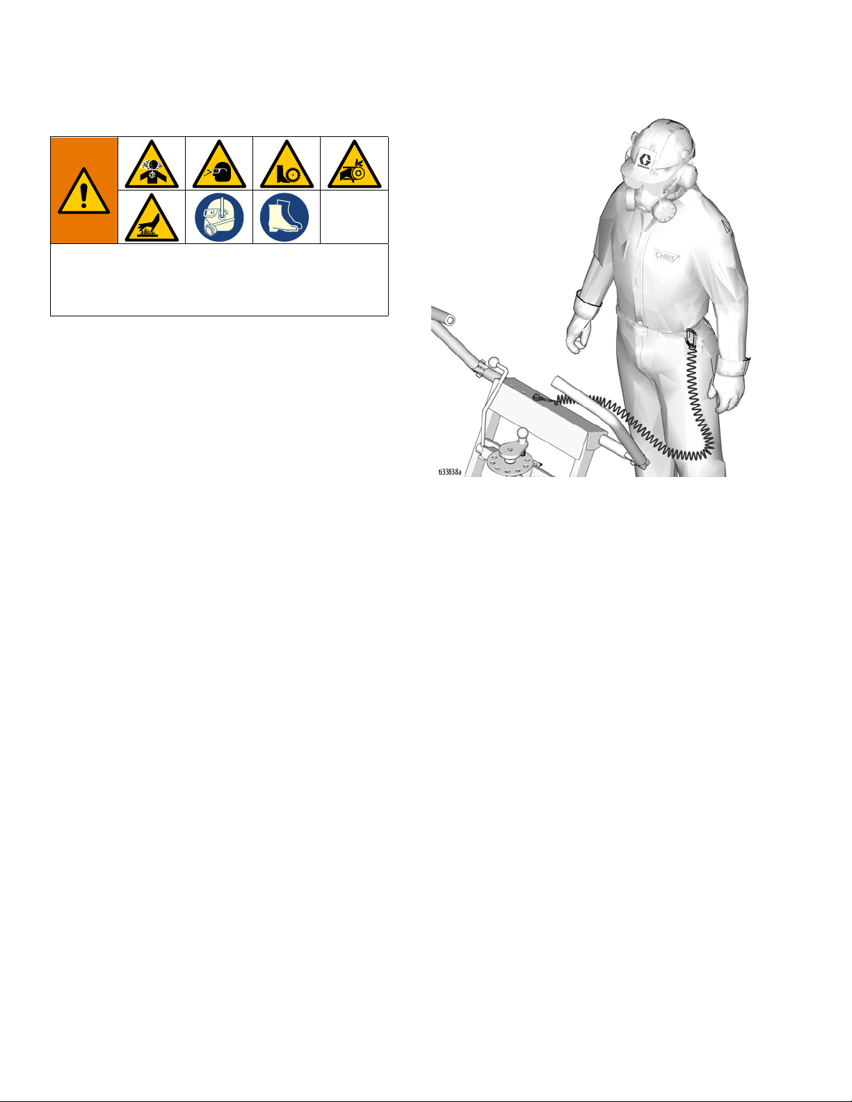
PERSONAL PROTECTIVE EQUIPMENT
You must wear appropriate protective equipment when operating, servicing, or when in the operating
area of the equipment to help protect you from serious injury, including eye injury, inhalation of dust or
chemicals, burns, and hearing loss. This equipment includes but is not limited to:
• Protective eye wear.
• Protective shoes.
• Gloves.
• Hearing protection.
• Properly fit-tested and government approved respirator suitable for the dust conditions.
3A5581C 3
Warnings
WARNING
FIRE AND EXPLOSION HAZARD
Flammable fumes, such as solvent and paint fumes, in work area can ignite or explode. To help prevent fire and explosion:
• Use equipment only in well ventilated area.
• Do not fill fuel tank while engine is running or hot; shut off engine and let it cool. Fuel is flammable
and can ignite or explode if spilled on hot surface.
• Keep work area free of debris, including solvent, rags and gasoline.
• Keep a fire extinguisher in work area.
CARBON MONOXIDE HAZARD
Exhaust contains poisonous carbon monoxide, which is colorless and odorless. Breathing carbon
monoxide can cause death.
• Do not operate in an enclosed area.
BATTERY HAZARD
Lead-acid batteries produce explosive gases and contain sulfuric acid that can cause severe burns. To
avoid sparks and injury when handling or working with a lead-acid battery:
• Read and follow the battery manufacturer’s warnings.
• Exercise caution when working with metallic tools or conductors to prevent short circuits and sparks.
• Keep all sparks, flames, and cigarettes away from batteries.
• Always wear protective eyewear and protective equipment for face, hands, and body.
• If you have direct contact with battery fluid, flush with water and consult a physician immediately.
• Installation and maintenance must be performed by knowledgeable personnel only.
Battery Disposal
Do not place batteries in the trash. Recycle batteries according to local regulations. In the USA and Canada call
1-800-822-8837 to find recycling location or go to www.call2recycle.org.
4 3A5581C
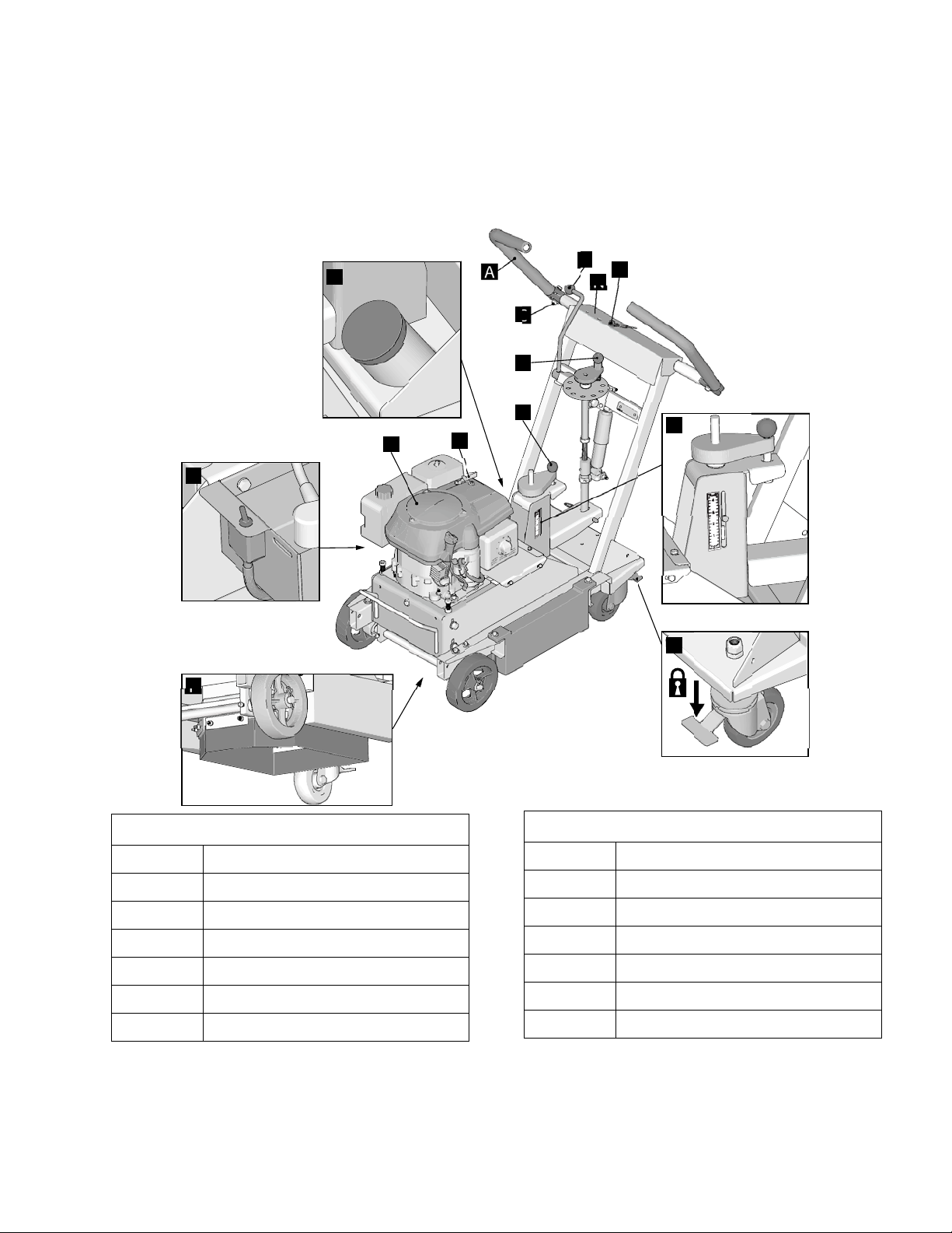
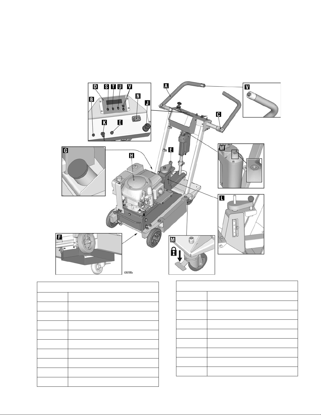
Component Identification
A
B
C
D
E
H
J
L
F
G
I
M
K
ti33805a
N
25M847
Component Identification
Component
Component
A Handlebar
B Cutter Head Engage Lever
C Handlebar Adjustment Bolts
D Cutter Head Adjustment Dial
E Pressure Control Dial
FDust Skirt
G Vacuum Port
H Engine
I Electric Start Engine Switch
J Engine Throttle
K Engine Kill Button
L Pressure Indicator
M Wheel Stop
N Hour Meter / Tachometer
3A5581C 5

Component Identification
Component Identification
25M847 (Series B)
Component
A Handlebar
B Cutter Head Engage Lever
C Handlebar Adjustment Bolts
D Cutter Head Adjustment Dial
E Pressure Control Dial
FDust Skirt
G Vacuum Port
6 3A5581C
HEngine
I Electric Start Engine Switch
J Engine Throttle
K Engine Kill Button
L Pressure Indicator
M Wheel Stop
N Hour Meter/Tachometer
Component
Component Identification
25N669
Component Identification
Component
A Handlebar
B Power Switch
C Handlebar Adjustment Bolts
DDCS Control
E Pressure Control Dial
FDust Skirt
G Vacuum Port
H Engine
I Electric Start Engine Switch
J Engine Throttle
3A5581C 7
K Engine Kill Button
L Pressure Indicator
M Wheel Stop
N Hour Meter/Tachometer
S Home Button
T Zero Button
U Cut Depth Button
V Up/Down Buttons
W Manual Height Adjustment
Component
Setup
Setup
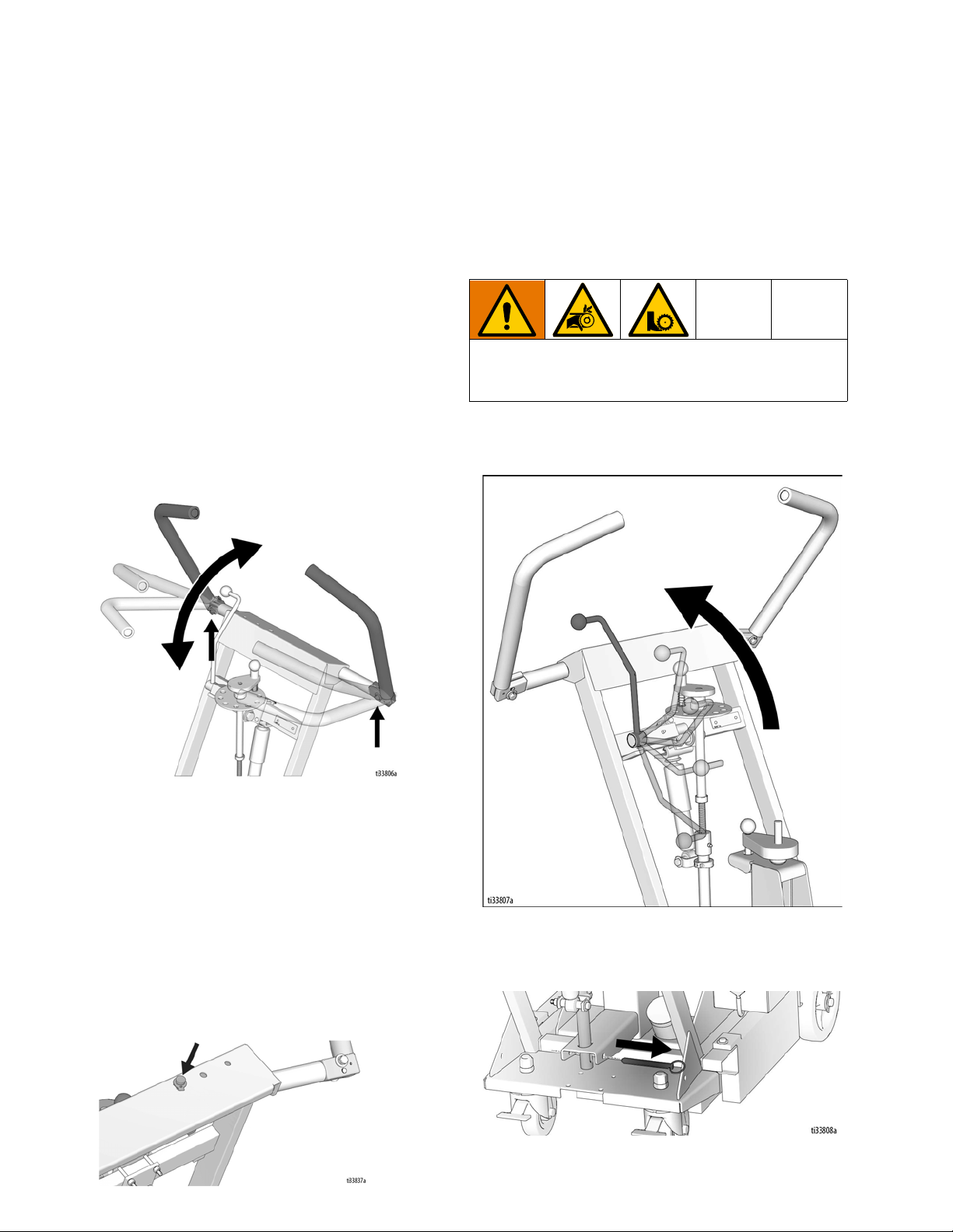
Handle Bar Adjustment
The handlebars are equipped with a high-density
vibration suppression material to reduce operator fatigue
when operating equipment. To adjust the handlebars to
a new position for different height operators please follow
these steps:
1. Using a 9/16” (14mm) wrench or socket, loosen the
bolts on both sides of the handlebars until the
handlebar moves freely.
2. Stand behind the machine and lightly tap the
handlebar to the desired position.
3. Re-tighten the bolts to 21.7 to 25 ft-lb (29-34 N•m)
to lock the handlebars into position.
NOTE: Never operate equipment with loose handlebars.
The bolts must be fastened tightly assuring the handle is
locked into position.
Cutter Head Installation/Replacement
Normal use will require periodic cutter head inspection
and may necessitate cutter replacement. Time of
replacement will vary according to usage and load
factors.
To avoid injury from unexpected start up, disconnect
spark plug wire and black battery cable before you
service your unit.
1. Non-DCS Models: Raise the Cutter Head Engage
Lever to the up position so the cutter head is off the
ground.
Engine Kill Button
In the event of a malfunction or an accident (such as the
machine operator falling or losing footing), the
GrindLazer is equipped with a corded Engine Kill Button.
Attach the end of the cord to the operator’s belt or wrist,
and snap the clip into place on the button by raising the
top of the Engine Kill Button and inserting the clip into the
gap. If the operator becomes distanced too far from the
machine, the cord will detach from the button and the
machine will stop running. The engine can also be
stopped by pressing down on the Engine Kill Button.
8 3A5581C
DCS Models: Press the Home Button on the DCS
Control so the cutter head is off the ground.
2. Remove Clevis Pin.
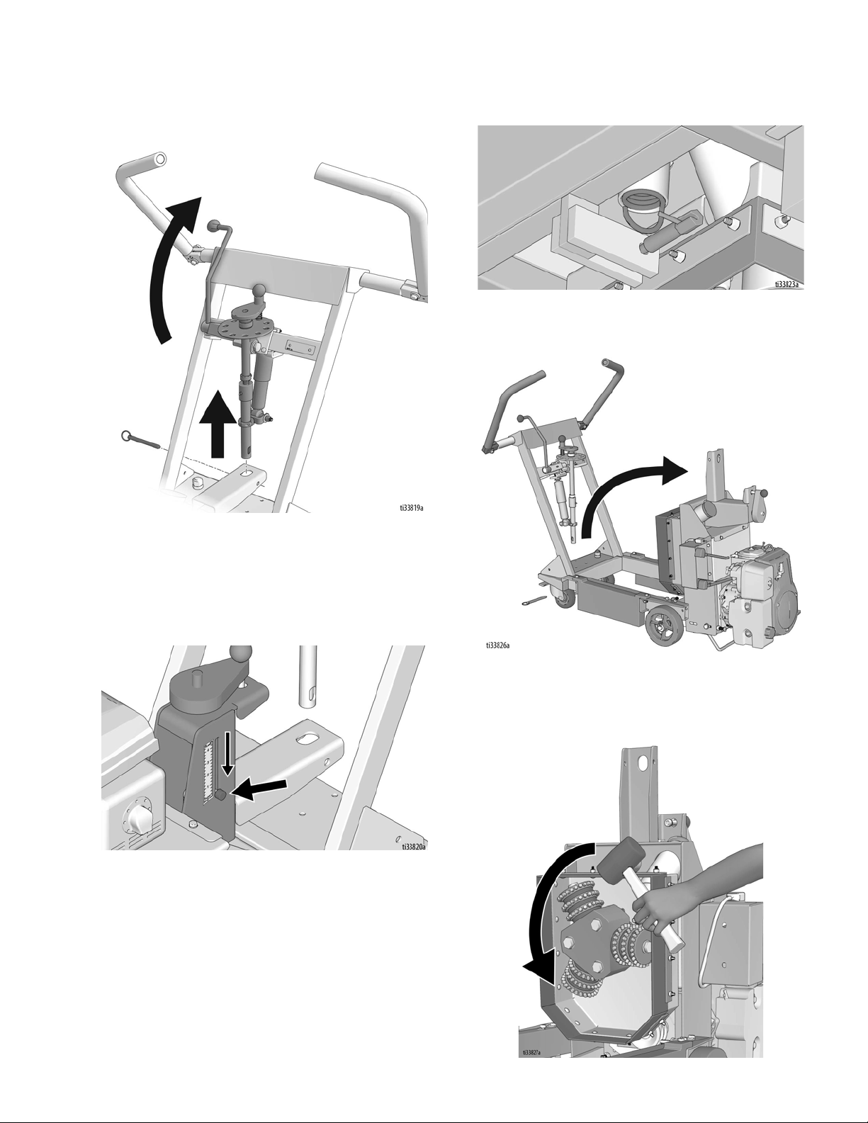
Setup
3. Non-DCS Models: Rotate Cutter Head Engage
Lever to upwards position to release lower linkage
from inner frame.
5. Unhook spring from the spring plunger (bottom rear
section of machine).
6. Rotate the inner frame upwards to gain access to
the cutters.
DCS Models: Press the Home Button on the DCS
Control.
4. Turn the pressure control dial until the indicator is at
“0”. This releases tension from the pressure control
spring.
7. If there is a cutter head attached, it must be
removed. To do so, strike the cutters in a counter
clockwise direction with a rubberized mallet or wood
block.
3A5581C 9
Setup
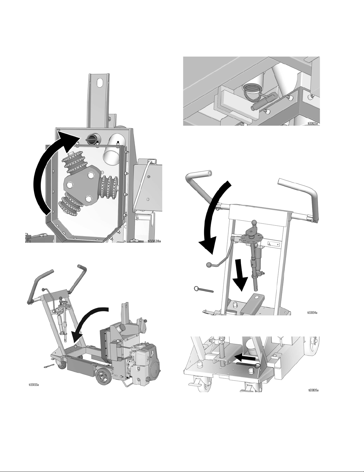
8. Install the new cutter assembly onto the machine by
spinning clockwise. Cutters will lock onto the
machine once surface removal is started.
10. Connect the spring to the spring plunger.
11. Lower the lower linkage into the slot in the inner
frame by rotating the Cutter Head Engage Lever
(non-DCS models), or by using the Down Button on
the DCS Control (DCS models).
9. Lower the inner frame back to a horizontal position.
12. Connect Clevis Pin.
10 3A5581C
Dust Control
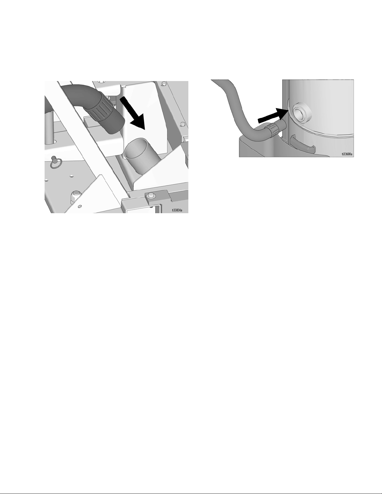
Vacuum Attachment
Setup
1. If using a vacuum, attach vacuum hose to the
Vacuum Port.
2. Attach vacuum hose to the Inlet Port on the Cyclone
Separator (optional) or vacuum.
3A5581C 11
Setup
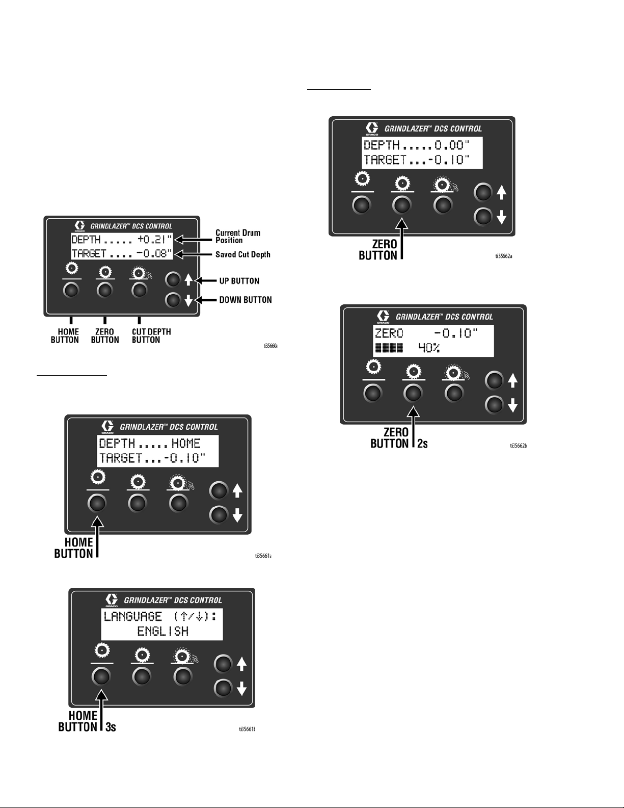
DCS Control (DCS Models only)
Buttons on the DCS Control have two functions, quick
press and long press. Quick press refers to pressing the
button and releasing the button quickly, while long press
is pressing the button and holding the button for two or
more seconds.
NOTE: “+” (plus) refers to above pavement surface. “-”
(minus) refers to below pavement surface.
Run Screen
Home Button
Zero Button
Quick Press: Takes the cutter head to the surface.
Long Press: Reprograms the zero point to the current
cutter head position.
Quick Press: Takes the cutter head to its highest
position.
Long Press: Brings up Menu Screen.
12 3A5581C
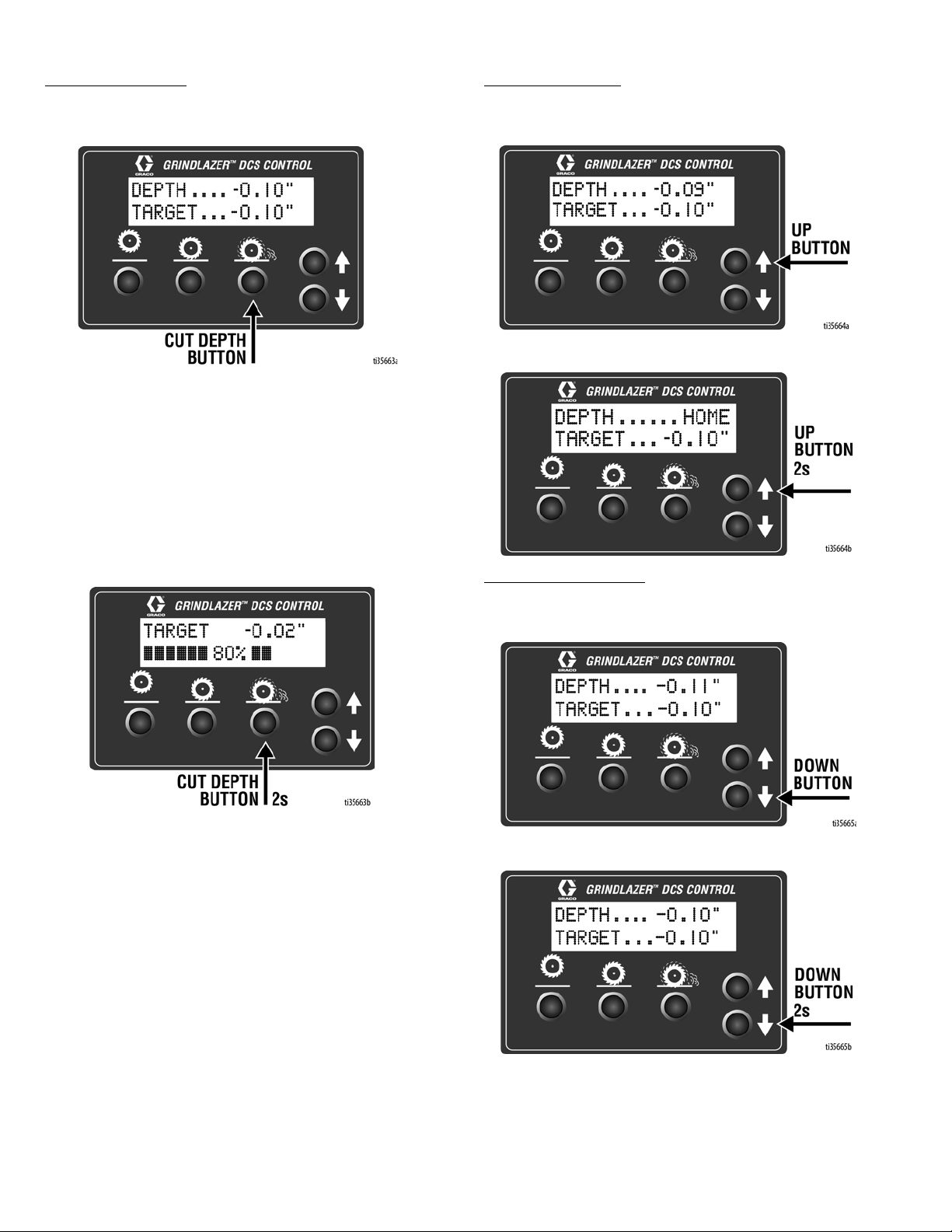
Cut Depth Button
Quick Press:
get.
Long Press:
- If at or above zero point: Opens new screen to
select desired cut depth using up/down buttons.
Takes the cutter head to the Cut Depth Tar-
•To exit without saving, quick press the Cut Depth
Button.
•To exit with saving, long press the Cut Depth Button.
Setup
Up Arrow Button*
Quick Press: Raises the cutter head by 0.01” (0.25mm,
10 mil).
Long Press: Raises the cutter head to Home position.
- If below zero point: Reprograms the Cut Depth Target to the current cutter head position.
Down Arrow Button*
Quick Press: Lowers the cutter head by 0.01” (25mm, 10
mil).
Long Press: Lowers the cutter head to Cut Depth Target.
*Handlebar Rocker Switch has the same functions as Up
and Down Arrow Buttons.
3A5581C 13
Setup
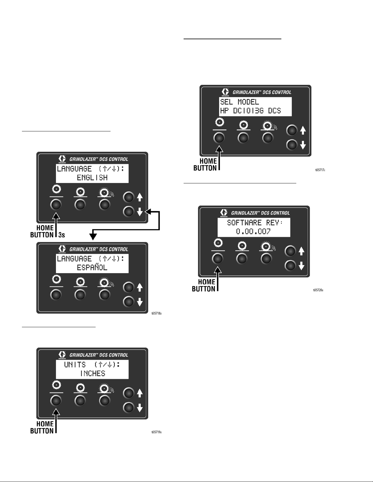
Menu Screens
To display the Menu Screens, hold down Home Button
from the Run Screen. To save menu settings and return
to Run Screen, hold down Home Button from any Menu
Screen.
To cycle through selections in each Menu Screen, use
Up and Down Arrow Buttons.
To advance to next Menu Screen, quick press the Home
Button.
Menu Screen #1 - Language
Select your desired language (English, Spanish,
French, German, or International Symbols).
Menu Screen #3 - Model Select
Your GrindLazer model name can be found on the handlebar dashboard label. Select the model on the DCS
Control which matches the model you have. This
ensures accurate depth readings. Hold down Up or
Down Arrow Buttons to cycle through models.
Menu Screen #4 - Software revision
Displays the revision of the software on the DCS Control.
Menu Screen #2 - Units
Select your desired depth units (inches, millimeters, or
mils).
14 3A5581C

Setup
Menu Screen #5 - Error Codes
Displays the most recent error code and the total number of times that error has occured. Cycle through previous error codes using Up/Down Buttons.
Error Codes
E04: High Voltage
E05: High Motor Current
E08: Low Voltage
E09: Hall Sensor Error
E12: High Current (short circuit)
E31: Home Button Error
E32: Zero Button Error
E33: Cut Depth Button Error
E34: Up Button Error
E35: Down Button Error
To clear an error code that appears while on the Run
Screen:
1. Turn DCS Power Switch OFF.
2. Address/Fix the issue.
3. Turn DCS Power Switch ON.
NOTE: See Repair Manual for more information on
Error Codes and Troubleshooting.
3A5581C 15
Operation
Operation
Do not start machine while cutter head is in contact
with the ground. Doing so can cause the operator to
lose control of the machine, resulting in property
damage and/or personal injury.
Machine Start Up
Before starting engine, perform the following:
• Read and understand engine manual.
• Make sure all guards are in place and secure.
• Make sure all mechanical fasteners are secure.
• Inspect for damage to engine and other exterior
surfaces.
• Inspect work area to locate any pipes, columns,
deck inserts, or other objects protruding from work
surface. Avoid these objects during operation.
Starting the Engine
• Connect Engine Kill Button Cord to operator and
machine.
• Open the fuel shut off on the gas tank and then
place the throttle lever at the “fast idle” position.
• Move the choke to closed.
• Push the Electric Start Engine Switch to start the
engine.
• After the engine starts, move choke to open.
• Set throttle to desired setting.
If the Engine Does Not Start
• Check engine for proper gas level.
• Check the spark plug. Make sure socket areas are
clean and clear of debris, and the proper gap is set.
Replace if needed.
• Battery might be dead. Try pulling the starter cord.
• Engine may have tilted backwards. If so, allow oil to
drain after removing spark plug.
• If engine still does not start, refer to the engine
manual.
• The engine will not start without the Corded Engine
Kill Clip securely in place.
16 3A5581C
Operation
C
B
A
Cutting Material
Maintain a safe operating distance from other people
in the work area. Avoid any pipes, columns, openings,
or any other objects protruding from your work surface.
1. Start Engine, see page 16.
2. Turn vacuum on, if using a vacuum.
Adjusting Cutter Head Angle
1. Locate a level surface for cutter adjustment. All four
wheels should be on a level surface for setup.
2. Run at about 1/3 engine throttle.
3. Non-DCS Models: Lower the Cutter Head Engage
Lever.
5. Move the machine away from the current position to
inspect the cut. Use the elevation screws in the front
of the machine to pitch the cutter to the correct
plane to create the desired cut pattern. Loosen bolts
A and B, then adjust bolt C to modify the cutter head
angle. Tighten bolts A and B when the desired
cutter angle is achieved.
4. Non-DCS Models: Slowly lower the Cutter Head
Adjustment Dial and at first sign of dust from the
cutters, raise the depth control knob up a couple of
turns and then lift the Cutter Head Engage Lever
back up.
DCS Models: Slowly lower the cutter head by pressing
the Down Button on the DCS Control repeatedly until the
first sign of dust from the cutters. Then raise the cutter
head off of the surface by pressing the Home Button.
3A5581C 17
Operation
Max
Min
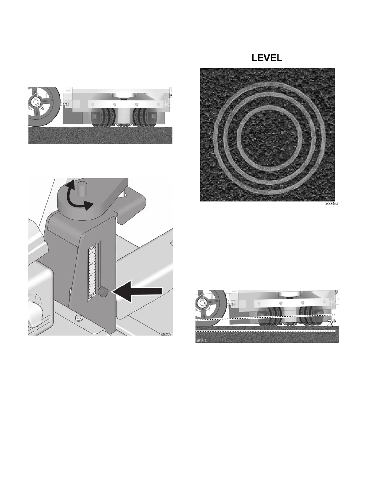
Concrete Cutting Setup
The machine set-up required when cutting
concrete is as follows:
1. Cutters should be parallel to the ground when
engaged.
2. Use the Pressure Control Dial to set the Pressure
Indicator to 0-1.
3. The cutting mark left by the machine should be an
even circle.
4. If the mark left by the machine is not as shown, adjust
the elevation screws accordingly. See page 17.
Asphalt Cutting Setup
The machine set-up required when cutting
asphalt is as follows:
1. Cutters should be at an angle no more than 2
degrees to the ground when engaged.
18 3A5581C
 Loading...