

Graco GrindLazer Pro RC813 G, GrindLazer Pro Series, GrindLazer Pro RC813 G DCS, 25N669, 25M847 Operation, Repair, And Parts
Page 1
www.graco.com/techsupport
?? ??
Operation, Repair, Parts
25M847
25M847 (Series B)
25N669
™
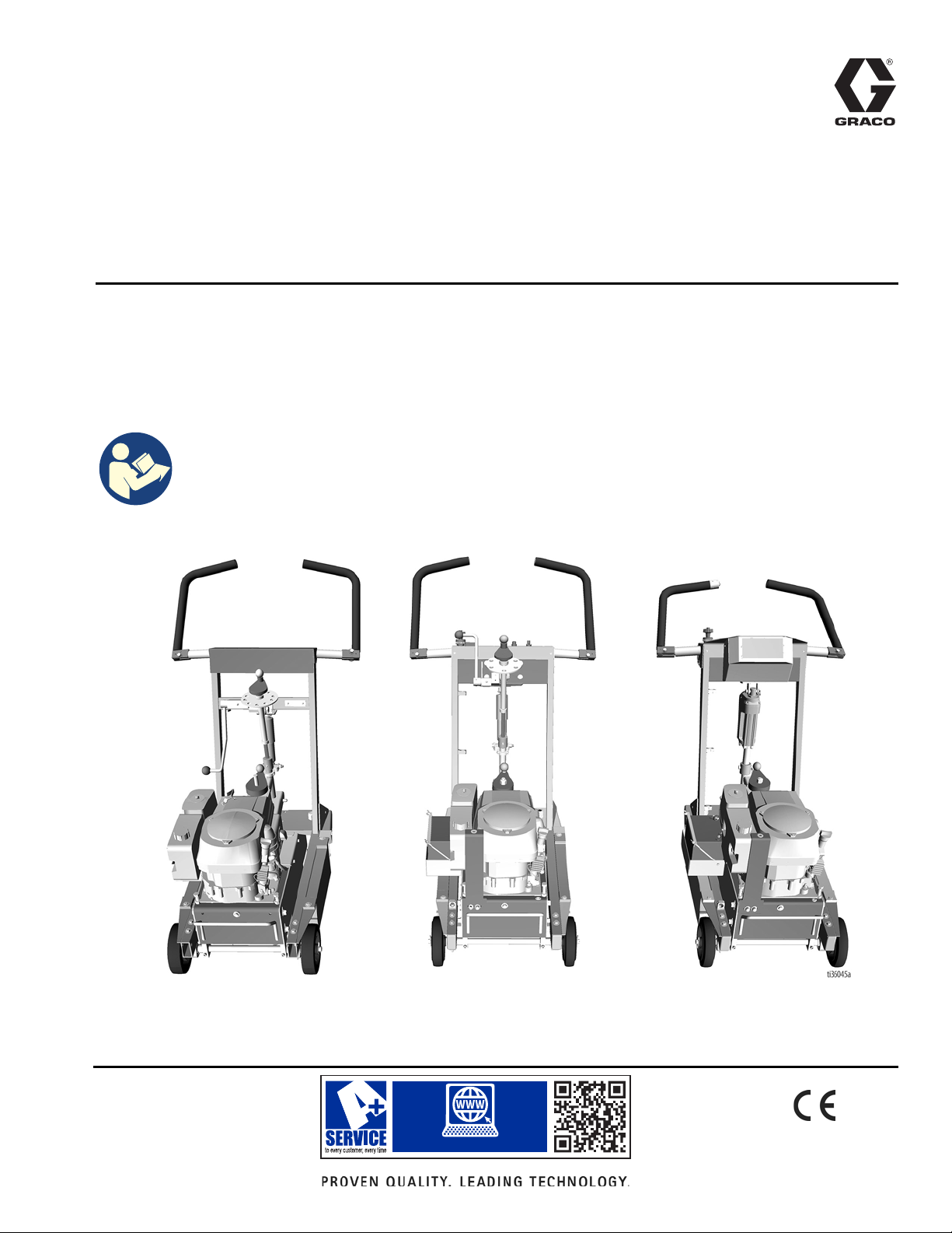
GrindLazer
For removal of materials from flat horizontal concrete and asphalt surfaces. For
professional use only.
Pro Series - Rotary Cut
Model 25M847 - GrindLazer Pro RC813 G (390 cc / 13hp Electric Start)
Model 25M847 - GrindLazer Pro RC813 G (390 cc / 13hp Electric Start) (Series B)
Model 25N669 - GrindLazer Pro RC813 G DCS (390 cc / 13hp Electric Start)
Important Safety Instructions
Read all warnings and instructions in this manual before using the
equipment. Be familiar with the controls and the proper usage of the
equipment. Save these instructions.
3A5581C
EN
Page 2

Contents
Contents
Warnings . . . . . . . . . . . . . . . . . . . . . . . . . . . . . . . . . . . . . . . . . . . . . . . . . . . . . . . . . . . . . . . . . . . . . . . . . . . . . . . . . . . . . . . . . 3
Battery Disposal . . . . . . . . . . . . . . . . . . . . . . . . . . . . . . . . . . . . . . . . . . . . . . . . . . . . . . . . . . . . . . . . . . . . . . . . . . . . . . . . 4
Component Identification . . . . . . . . . . . . . . . . . . . . . . . . . . . . . . . . . . . . . . . . . . . . . . . . . . . . . . . . . . . . . . . . . . . . . . . . . . . 5
25M847 . . . . . . . . . . . . . . . . . . . . . . . . . . . . . . . . . . . . . . . . . . . . . . . . . . . . . . . . . . . . . . . . . . . . . . . . . . . . . . . . . . . . . . . 5
Component Identification . . . . . . . . . . . . . . . . . . . . . . . . . . . . . . . . . . . . . . . . . . . . . . . . . . . . . . . . . . . . . . . . . . . . . . . . . . . 6
25M847 (Series B) . . . . . . . . . . . . . . . . . . . . . . . . . . . . . . . . . . . . . . . . . . . . . . . . . . . . . . . . . . . . . . . . . . . . . . . . . . . . . . 6
Component Identification . . . . . . . . . . . . . . . . . . . . . . . . . . . . . . . . . . . . . . . . . . . . . . . . . . . . . . . . . . . . . . . . . . . . . . . . . . . 7
25N669 . . . . . . . . . . . . . . . . . . . . . . . . . . . . . . . . . . . . . . . . . . . . . . . . . . . . . . . . . . . . . . . . . . . . . . . . . . . . . . . . . . . . . . . 7
Setup . . . . . . . . . . . . . . . . . . . . . . . . . . . . . . . . . . . . . . . . . . . . . . . . . . . . . . . . . . . . . . . . . . . . . . . . . . . . . . . . . . . . . . . . . . . . 8
Handle Bar Adjustment . . . . . . . . . . . . . . . . . . . . . . . . . . . . . . . . . . . . . . . . . . . . . . . . . . . . . . . . . . . . . . . . . . . . . . . . . . . 8
Engine Kill Button . . . . . . . . . . . . . . . . . . . . . . . . . . . . . . . . . . . . . . . . . . . . . . . . . . . . . . . . . . . . . . . . . . . . . . . . . . . . . . . 8
Cutter Head Installation/Replacement . . . . . . . . . . . . . . . . . . . . . . . . . . . . . . . . . . . . . . . . . . . . . . . . . . . . . . . . . . . . . . . 8
Dust Control . . . . . . . . . . . . . . . . . . . . . . . . . . . . . . . . . . . . . . . . . . . . . . . . . . . . . . . . . . . . . . . . . . . . . . . . . . . . . . . . . . 11
DCS Control (DCS Models only) . . . . . . . . . . . . . . . . . . . . . . . . . . . . . . . . . . . . . . . . . . . . . . . . . . . . . . . . . . . . . . . . . . . 12
Operation . . . . . . . . . . . . . . . . . . . . . . . . . . . . . . . . . . . . . . . . . . . . . . . . . . . . . . . . . . . . . . . . . . . . . . . . . . . . . . . . . . . . . . . 16
Machine Start Up . . . . . . . . . . . . . . . . . . . . . . . . . . . . . . . . . . . . . . . . . . . . . . . . . . . . . . . . . . . . . . . . . . . . . . . . . . . . . . 16
Cutting Material . . . . . . . . . . . . . . . . . . . . . . . . . . . . . . . . . . . . . . . . . . . . . . . . . . . . . . . . . . . . . . . . . . . . . . . . . . . . . . . . 17
Stop Cutting Material . . . . . . . . . . . . . . . . . . . . . . . . . . . . . . . . . . . . . . . . . . . . . . . . . . . . . . . . . . . . . . . . . . . . . . . . . . . 20
DCS Instructions . . . . . . . . . . . . . . . . . . . . . . . . . . . . . . . . . . . . . . . . . . . . . . . . . . . . . . . . . . . . . . . . . . . . . . . . . . . . . . . 21
Maintenance . . . . . . . . . . . . . . . . . . . . . . . . . . . . . . . . . . . . . . . . . . . . . . . . . . . . . . . . . . . . . . . . . . . . . . . . . . . . . . . . . . . . . 23
DCS Control Translations (DCS Models only) . . . . . . . . . . . . . . . . . . . . . . . . . . . . . . . . . . . . . . . . . . . . . . . . . . . . . . . . . . 24
Repair . . . . . . . . . . . . . . . . . . . . . . . . . . . . . . . . . . . . . . . . . . . . . . . . . . . . . . . . . . . . . . . . . . . . . . . . . . . . . . . . . . . . . . . . . . 26
Belt Replacement and Adjustment . . . . . . . . . . . . . . . . . . . . . . . . . . . . . . . . . . . . . . . . . . . . . . . . . . . . . . . . . . . . . . . . . 26
Drive Pulley Replacement . . . . . . . . . . . . . . . . . . . . . . . . . . . . . . . . . . . . . . . . . . . . . . . . . . . . . . . . . . . . . . . . . . . . . . . . 27
Engine Pulley Replacement . . . . . . . . . . . . . . . . . . . . . . . . . . . . . . . . . . . . . . . . . . . . . . . . . . . . . . . . . . . . . . . . . . . . . . 28
Troubleshooting . . . . . . . . . . . . . . . . . . . . . . . . . . . . . . . . . . . . . . . . . . . . . . . . . . . . . . . . . . . . . . . . . . . . . . . . . . . . . . . . . . 29
DCS Models only . . . . . . . . . . . . . . . . . . . . . . . . . . . . . . . . . . . . . . . . . . . . . . . . . . . . . . . . . . . . . . . . . . . . . . . . . . . . . . 30
DCS Error Codes . . . . . . . . . . . . . . . . . . . . . . . . . . . . . . . . . . . . . . . . . . . . . . . . . . . . . . . . . . . . . . . . . . . . . . . . . . . . . . 31
DCS Actuator Rod Does Not Move . . . . . . . . . . . . . . . . . . . . . . . . . . . . . . . . . . . . . . . . . . . . . . . . . . . . . . . . . . . . . . . . . 33
Parts . . . . . . . . . . . . . . . . . . . . . . . . . . . . . . . . . . . . . . . . . . . . . . . . . . . . . . . . . . . . . . . . . . . . . . . . . . . . . . . . . . . . . . . . . . . 34
Outer Frame Assembly - 25M847 . . . . . . . . . . . . . . . . . . . . . . . . . . . . . . . . . . . . . . . . . . . . . . . . . . . . . . . . . . . . . . . . . . 34
Outer Frame Assembly Parts List - 25M847 . . . . . . . . . . . . . . . . . . . . . . . . . . . . . . . . . . . . . . . . . . . . . . . . . . . . . . . . . . 35
Shock Assembly - 25M847 . . . . . . . . . . . . . . . . . . . . . . . . . . . . . . . . . . . . . . . . . . . . . . . . . . . . . . . . . . . . . . . . . . . . . . . 36
Shock Assembly Parts List . . . . . . . . . . . . . . . . . . . . . . . . . . . . . . . . . . . . . . . . . . . . . . . . . . . . . . . . . . . . . . . . . . . . . . . 36
Adjustable Handles - 25M847 . . . . . . . . . . . . . . . . . . . . . . . . . . . . . . . . . . . . . . . . . . . . . . . . . . . . . . . . . . . . . . . . . . . . . 37
Adjustable Handles Parts List - 25M847 . . . . . . . . . . . . . . . . . . . . . . . . . . . . . . . . . . . . . . . . . . . . . . . . . . . . . . . . . . . . . 37
Adjustable Handles - 25M847 (Series B) & 25N669 . . . . . . . . . . . . . . . . . . . . . . . . . . . . . . . . . . . . . . . . . . . . . . . . . . . . 38
Adjustable Handles Parts List - 25M847 (Series B) . . . . . . . . . . . . . . . . . . . . . . . . . . . . . . . . . . . . . . . . . . . . . . . . . . . . 39
Adjustable Handles Parts List - 25N669 . . . . . . . . . . . . . . . . . . . . . . . . . . . . . . . . . . . . . . . . . . . . . . . . . . . . . . . . . . . . . 39
Drive System Assembly - 25M847 . . . . . . . . . . . . . . . . . . . . . . . . . . . . . . . . . . . . . . . . . . . . . . . . . . . . . . . . . . . . . . . . . 40
Drive System Parts List - 25M847 . . . . . . . . . . . . . . . . . . . . . . . . . . . . . . . . . . . . . . . . . . . . . . . . . . . . . . . . . . . . . . . . . 41
Drive System Assembly - 25M847 (Series B) & 25N669 . . . . . . . . . . . . . . . . . . . . . . . . . . . . . . . . . . . . . . . . . . . . . . . . 42
Drive System Parts List - 25M847 (Series B) & 25N669 . . . . . . . . . . . . . . . . . . . . . . . . . . . . . . . . . . . . . . . . . . . . . . . . 43
Front Assembly - 25M847 . . . . . . . . . . . . . . . . . . . . . . . . . . . . . . . . . . . . . . . . . . . . . . . . . . . . . . . . . . . . . . . . . . . . . . . . 44
Front Assembly Parts List - 25M847 . . . . . . . . . . . . . . . . . . . . . . . . . . . . . . . . . . . . . . . . . . . . . .
Front Assembly - 25M847 (Series B) & 25N669 . . . . . . . . . . . . . . . . . . . . . . . . . . . . . . . . . . . . . . . . . . . . . . . . . . . . . . . 46
Front Assembly Parts List - 25M847 (Series B) & 25N669 . . . . . . . . . . . . . . . . . . . . . . . . . . . . . . . . . . . . . . . . . . . . . . . 47
Controls Assembly - 25M847 (Series B) . . . . . . . . . . . . . . . . . . . . . . . . . . . . . . . . . . . . . . . . . . . . . . . . . . . . . . . . . . . . . 48
Controls Assembly Parts List - 25M847 (Series B) . . . . . . . . . . . . . . . . . . . . . . . . . . . . . . . . . . . . . . . . . . . . . . . . . . . . . 49
Controls Assembly - 25N669 . . . . . . . . . . . . . . . . . . . . . . . . . . . . . . . . . . . . . . . . . . . . . . . . . . . . . . . . . . . . . . . . . . . . . 50
Controls Assembly Parts List - 25N669 . . . . . . . . . . . . . . . . . . . . . . . . . . . . . . . . . . . . . . . . . . . . . . . . . . . . . . . . . . . . . 51
Spindle Cutter Assembly (24 pin) . . . . . . . . . . . . . . . . . . . . . . . . . . . . . . . . . . . . . . . . . . . . . . . . . . . . . . . . . . . . . . . . . . 52
Spindle Cutter Assembly Parts List - 25N363 . . . . . . . . . . . . . . . . . . . . . . . . . . . . . . . . . . . . . . . . . . . . . . . . . . . . . . . . . 52
DCS Control Box 18A790 . . . . . . . . . . . . . . . . . . . . . . . . . . . . . . . . . . . . . . . . . . . . . . . . . . . . . . . . . . . . . . . . . . . . . . . . . . 53
25N669 only . . . . . . . . . . . . . . . . . . . . . . . . . . . . . . . . . . . . . . . . . . . . . . . . . . . . . . . . . . . . . . . . . . . . . . . . . . . . . . . . . . 53
Parts List . . . . . . . . . . . . . . . . . . . . . . . . . . . . . . . . . . . . . . . . . . . . . . . . . . . . . . . . . . . . . . . . . . . . . . . . . . . . . . . . . . . . . 53
Wiring Diagram . . . . . . . . . . . . . . . . . . . . . . . . . . . . . . . . . . . . . . . . . . . . . . . . . . . . . . . . . . . . . . . . . . . . . . . . . . . . . . . . . . . 54
DCS System . . . . . . . . . . . . . . . . . . . . . . . . . . . . . . . . . . . . . . . . . . . . . . . . . . . . . . . . . . . . . . . . . . . . . . . . . . . . . . . . . . 54
DCS Control Box . . . . . . . . . . . . . . . . . . . . . . . . . . . . . . . . . . . . . . . . . . . . . . . . . . . . . . . . . . . . . . . . . . . . . . . . . . . . . . . 55
Technical Data . . . . . . . . . . . . . . . . . . . . . . . . . . . . . . . . . . . . . . . . . . . . . . . . . . . . . . . . . . . . . . . . . . . . . . . . . . . . . . . . . . . 56
Graco Standard Warranty . . . . . . . . . . . . . . . . . . . . . . . . . . . . . . . . . . . . . . . . . . . . . . . . . . . . . . . . . . . . . . . . . . . . . . . . . . 57
. . . . . . . . . . . . . . . . . . 45
2 3A5581C
Page 3
Warnings
WARNING
The following warnings are for the setup, use, grounding, maintenance, and repair of this equipment. The exclamation
point symbol alerts you to a general warning and the hazard symbols refer to procedure-specific risks. When these
symbols appear in the body of this manual or on warning labels, refer back to these Warnings. Product-specific hazard
symbols and warnings not covered in this section may appear throughout the body of this manual where applicable.
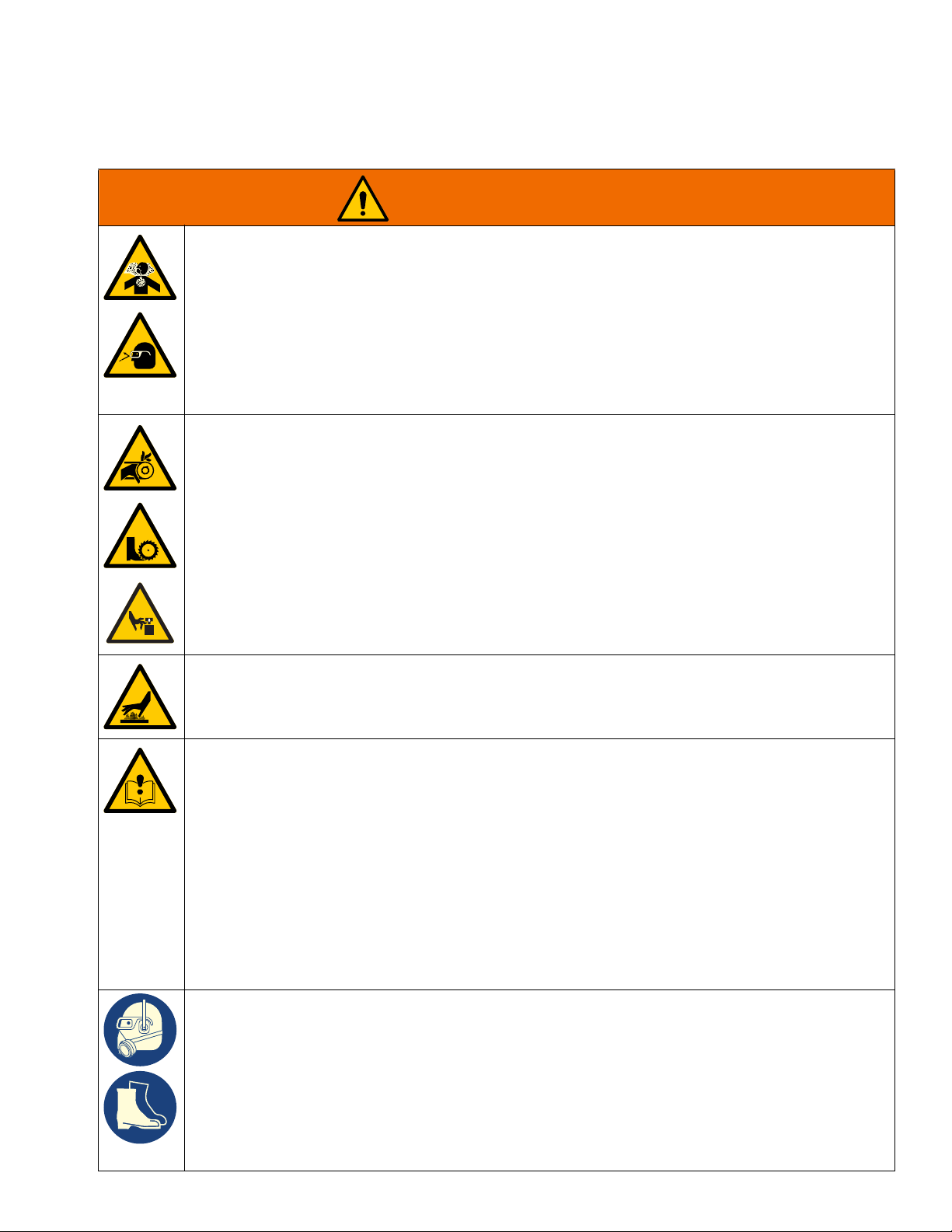
DUST AND DEBRIS HAZARD
Grinding concrete and other surfaces with this equipment can create dust that contains hazardous
substances. Grinding can also create flying debris.
To reduce the risk of serious injury:
• Control the dust to meet all applicable workplace regulations.
• Wear protective eye wear and a properly fit-tested and government approved respirator suitable for
the dust conditions.
• Use equipment only in a well-ventilated area.
• Grinding equipment must be used only by trained personnel who understand the applicable workplace regulations.
ENTANGLEMENT AND MOVING PARTS HAZARD
Moving parts can pinch, cut or amputate fingers and other body parts.
• Keep clear of moving parts.
• Do not operate equipment with protective guards or covers removed.
• Do not wear loose clothing, jewelry or long hair while operating equipment.
• Before checking, moving, or servicing equipment, disconnect battery.
Warnings
BURN HAZARD
Cutters and engine can become very hot during operation. To avoid severe burns, do not touch hot
equipment. Wait until equipment has cooled completely.
EQUIPMENT MISUSE HAZARD
Misuse can cause death or serious injury.
• Do not operate the unit when fatigued or under the influence of drugs or alcohol.
• Do not leave the work area while equipment is energized. Turn off all equipment when equipment
is not in use.
• Check equipment daily. Repair or replace worn or damaged parts immediately with genuine manufacturer’s replacement parts only.
• Do not alter or modify equipment.
• Use equipment only for its intended purpose. Call your distributor for information.
• Keep children and animals away from work area.
• Comply with all applicable safety regulations.
• Maintain a safe operating distance from other people in the work area.
• Avoid any pipes, columns, openings, or any other objects protruding from work surface.
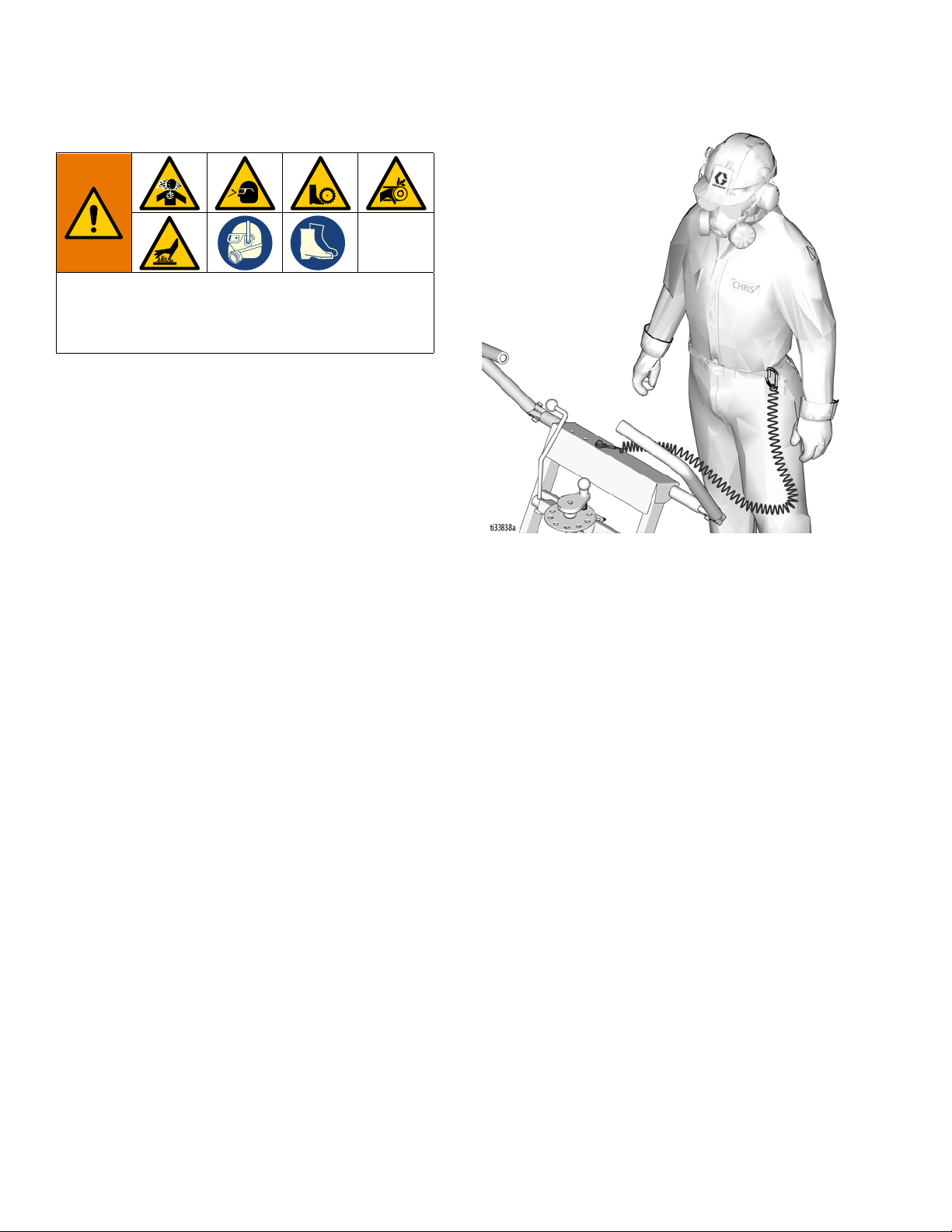
PERSONAL PROTECTIVE EQUIPMENT
You must wear appropriate protective equipment when operating, servicing, or when in the operating
area of the equipment to help protect you from serious injury, including eye injury, inhalation of dust or
chemicals, burns, and hearing loss. This equipment includes but is not limited to:
• Protective eye wear.
• Protective shoes.
• Gloves.
• Hearing protection.
• Properly fit-tested and government approved respirator suitable for the dust conditions.
3A5581C 3
Page 4
Warnings
WARNING
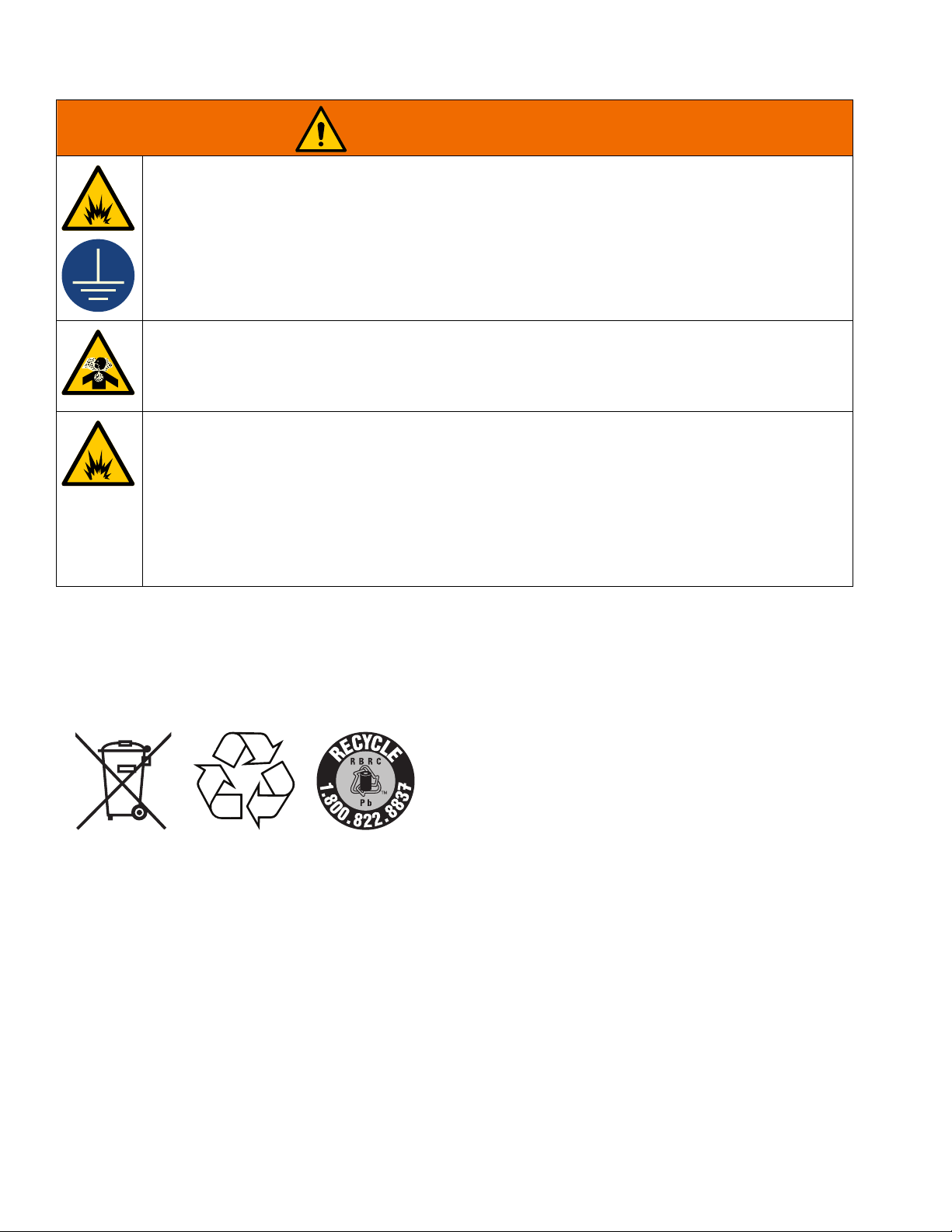
FIRE AND EXPLOSION HAZARD
Flammable fumes, such as solvent and paint fumes, in work area can ignite or explode. To help prevent fire and explosion:
• Use equipment only in well ventilated area.
• Do not fill fuel tank while engine is running or hot; shut off engine and let it cool. Fuel is flammable
and can ignite or explode if spilled on hot surface.
• Keep work area free of debris, including solvent, rags and gasoline.
• Keep a fire extinguisher in work area.
CARBON MONOXIDE HAZARD
Exhaust contains poisonous carbon monoxide, which is colorless and odorless. Breathing carbon
monoxide can cause death.
• Do not operate in an enclosed area.
BATTERY HAZARD
Lead-acid batteries produce explosive gases and contain sulfuric acid that can cause severe burns. To
avoid sparks and injury when handling or working with a lead-acid battery:
• Read and follow the battery manufacturer’s warnings.
• Exercise caution when working with metallic tools or conductors to prevent short circuits and sparks.
• Keep all sparks, flames, and cigarettes away from batteries.
• Always wear protective eyewear and protective equipment for face, hands, and body.
• If you have direct contact with battery fluid, flush with water and consult a physician immediately.
• Installation and maintenance must be performed by knowledgeable personnel only.
Battery Disposal
Do not place batteries in the trash. Recycle batteries according to local regulations. In the USA and Canada call
1-800-822-8837 to find recycling location or go to www.call2recycle.org.
4 3A5581C
Page 5
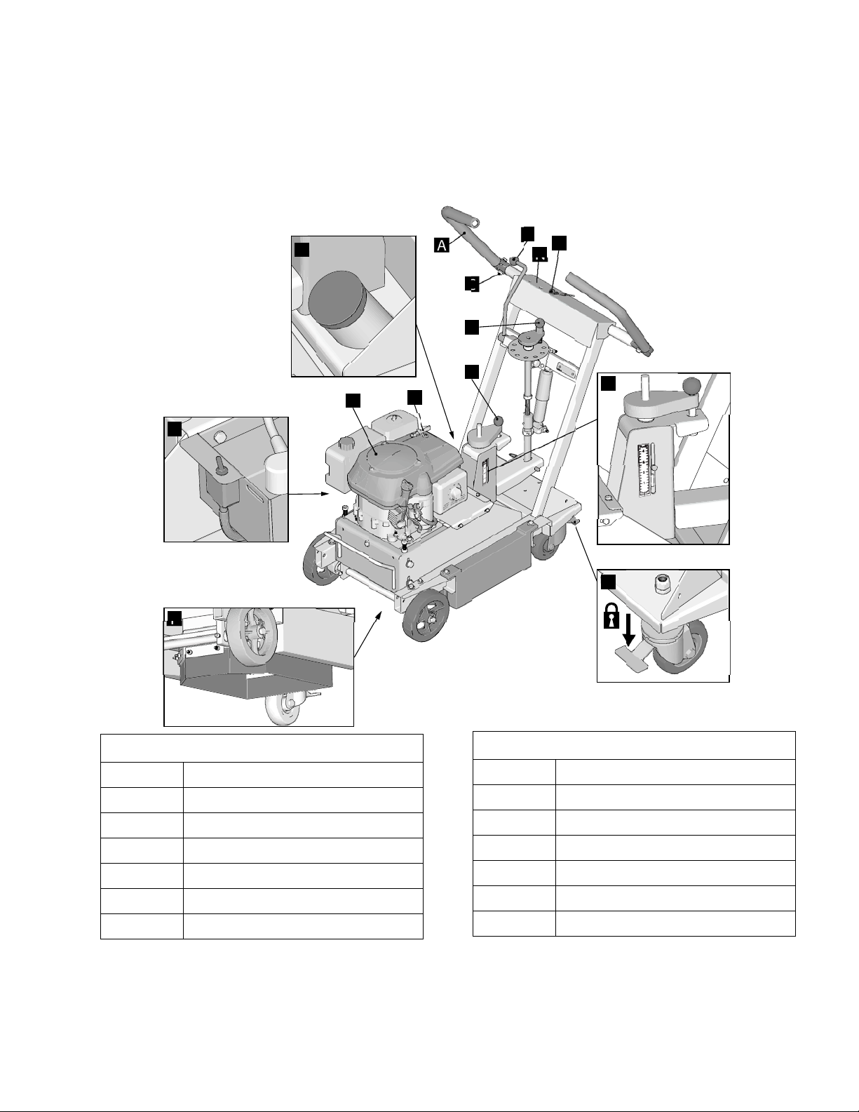
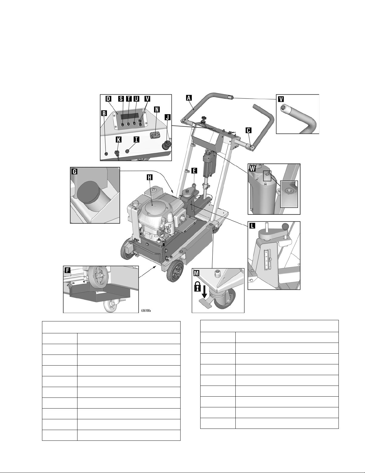
Component Identification
A
B
C
D
E
H
J
L
F
G
I
M
K
ti33805a
N
25M847
Component Identification
Component
Component
A Handlebar
B Cutter Head Engage Lever
C Handlebar Adjustment Bolts
D Cutter Head Adjustment Dial
E Pressure Control Dial
FDust Skirt
G Vacuum Port
H Engine
I Electric Start Engine Switch
J Engine Throttle
K Engine Kill Button
L Pressure Indicator
M Wheel Stop
N Hour Meter / Tachometer
3A5581C 5
Page 6

Component Identification
Component Identification
25M847 (Series B)
Component
A Handlebar
B Cutter Head Engage Lever
C Handlebar Adjustment Bolts
D Cutter Head Adjustment Dial
E Pressure Control Dial
FDust Skirt
G Vacuum Port
6 3A5581C
HEngine
I Electric Start Engine Switch
J Engine Throttle
K Engine Kill Button
L Pressure Indicator
M Wheel Stop
N Hour Meter/Tachometer
Component
Page 7
Component Identification
25N669
Component Identification
Component
A Handlebar
B Power Switch
C Handlebar Adjustment Bolts
DDCS Control
E Pressure Control Dial
FDust Skirt
G Vacuum Port
H Engine
I Electric Start Engine Switch
J Engine Throttle
3A5581C 7
K Engine Kill Button
L Pressure Indicator
M Wheel Stop
N Hour Meter/Tachometer
S Home Button
T Zero Button
U Cut Depth Button
V Up/Down Buttons
W Manual Height Adjustment
Component
Page 8
Setup
Setup
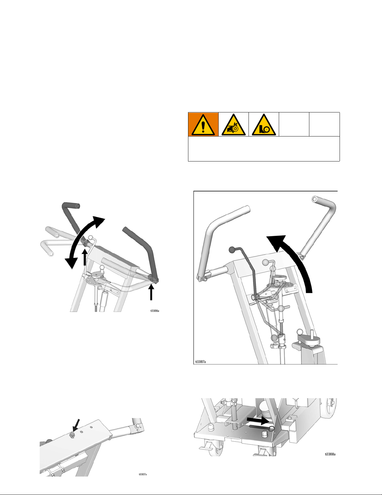
Handle Bar Adjustment
The handlebars are equipped with a high-density
vibration suppression material to reduce operator fatigue
when operating equipment. To adjust the handlebars to
a new position for different height operators please follow
these steps:
1. Using a 9/16” (14mm) wrench or socket, loosen the
bolts on both sides of the handlebars until the
handlebar moves freely.
2. Stand behind the machine and lightly tap the
handlebar to the desired position.
3. Re-tighten the bolts to 21.7 to 25 ft-lb (29-34 N•m)
to lock the handlebars into position.
NOTE: Never operate equipment with loose handlebars.
The bolts must be fastened tightly assuring the handle is
locked into position.
Cutter Head Installation/Replacement
Normal use will require periodic cutter head inspection
and may necessitate cutter replacement. Time of
replacement will vary according to usage and load
factors.
To avoid injury from unexpected start up, disconnect
spark plug wire and black battery cable before you
service your unit.
1. Non-DCS Models: Raise the Cutter Head Engage
Lever to the up position so the cutter head is off the
ground.
Engine Kill Button
In the event of a malfunction or an accident (such as the
machine operator falling or losing footing), the
GrindLazer is equipped with a corded Engine Kill Button.
Attach the end of the cord to the operator’s belt or wrist,
and snap the clip into place on the button by raising the
top of the Engine Kill Button and inserting the clip into the
gap. If the operator becomes distanced too far from the
machine, the cord will detach from the button and the
machine will stop running. The engine can also be
stopped by pressing down on the Engine Kill Button.
8 3A5581C
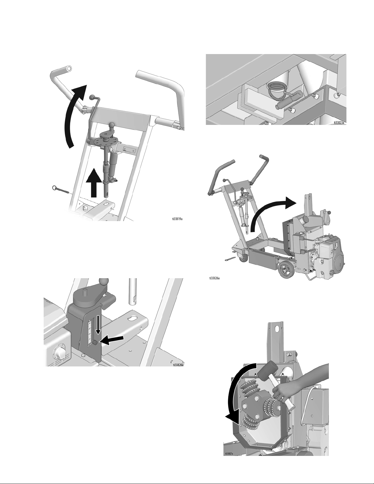
DCS Models: Press the Home Button on the DCS
Control so the cutter head is off the ground.
2. Remove Clevis Pin.
Page 9
Setup
3. Non-DCS Models: Rotate Cutter Head Engage
Lever to upwards position to release lower linkage
from inner frame.
5. Unhook spring from the spring plunger (bottom rear
section of machine).
6. Rotate the inner frame upwards to gain access to
the cutters.
DCS Models: Press the Home Button on the DCS
Control.
4. Turn the pressure control dial until the indicator is at
“0”. This releases tension from the pressure control
spring.
7. If there is a cutter head attached, it must be
removed. To do so, strike the cutters in a counter
clockwise direction with a rubberized mallet or wood
block.
3A5581C 9
Page 10
Setup
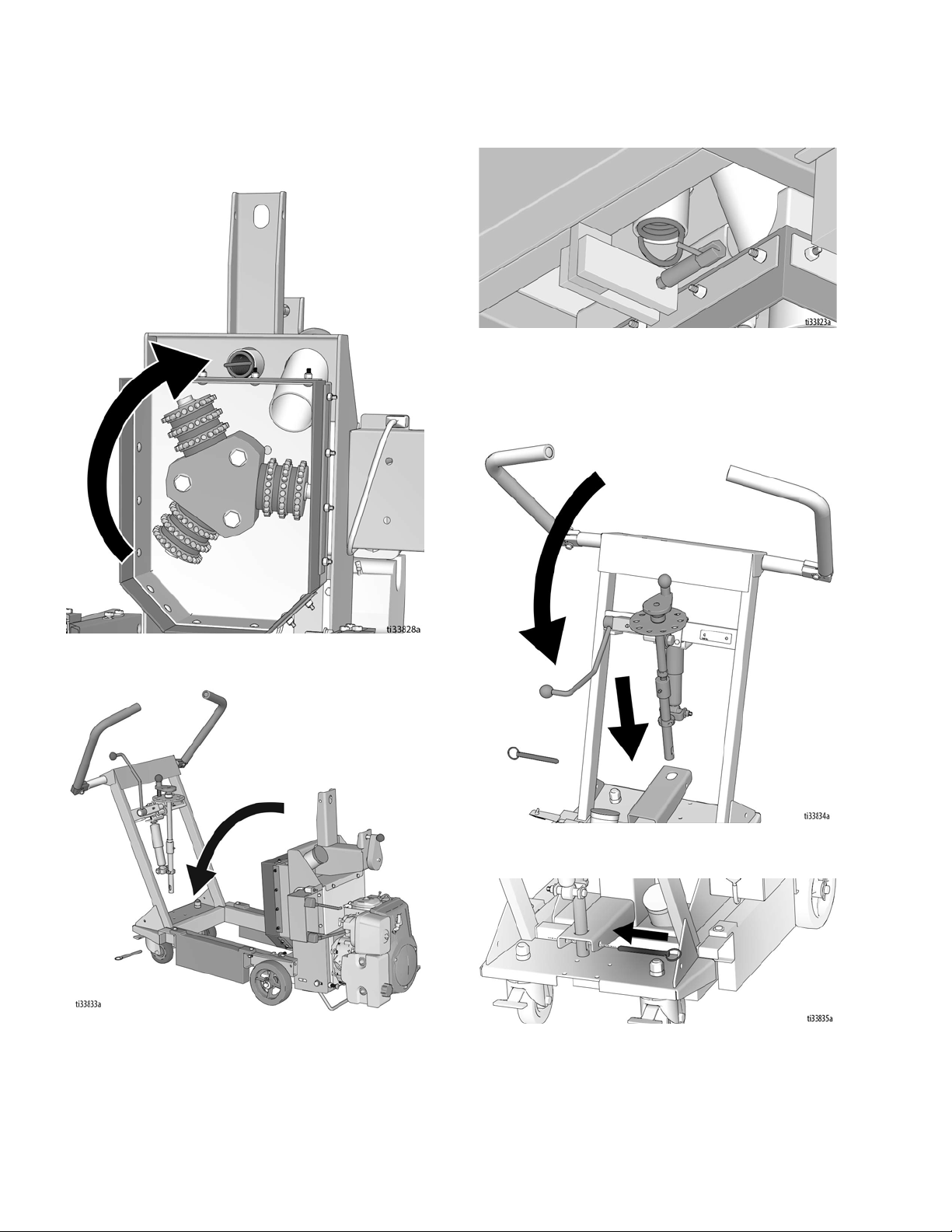
8. Install the new cutter assembly onto the machine by
spinning clockwise. Cutters will lock onto the
machine once surface removal is started.
10. Connect the spring to the spring plunger.
11. Lower the lower linkage into the slot in the inner
frame by rotating the Cutter Head Engage Lever
(non-DCS models), or by using the Down Button on
the DCS Control (DCS models).
9. Lower the inner frame back to a horizontal position.
12. Connect Clevis Pin.
10 3A5581C
Page 11
Dust Control
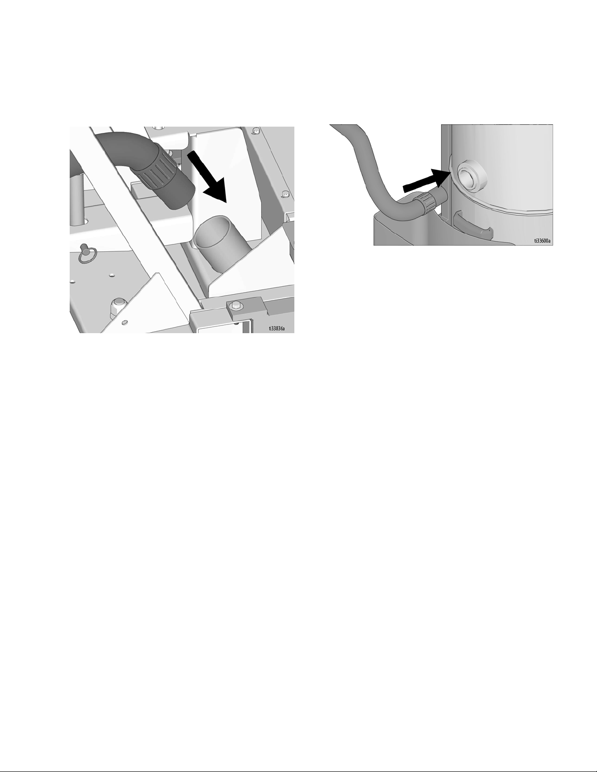
Vacuum Attachment
Setup
1. If using a vacuum, attach vacuum hose to the
Vacuum Port.
2. Attach vacuum hose to the Inlet Port on the Cyclone
Separator (optional) or vacuum.
3A5581C 11
Page 12
Setup
DCS Control (DCS Models only)
Buttons on the DCS Control have two functions, quick
press and long press. Quick press refers to pressing the
button and releasing the button quickly, while long press
is pressing the button and holding the button for two or
more seconds.
NOTE: “+” (plus) refers to above pavement surface. “-”
(minus) refers to below pavement surface.
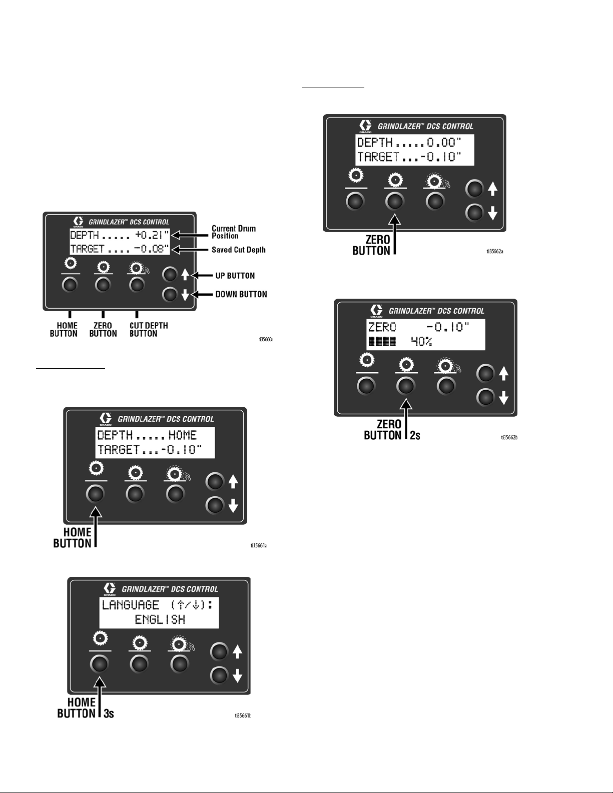
Run Screen
Home Button
Zero Button
Quick Press: Takes the cutter head to the surface.
Long Press: Reprograms the zero point to the current
cutter head position.
Quick Press: Takes the cutter head to its highest
position.
Long Press: Brings up Menu Screen.
12 3A5581C
Page 13
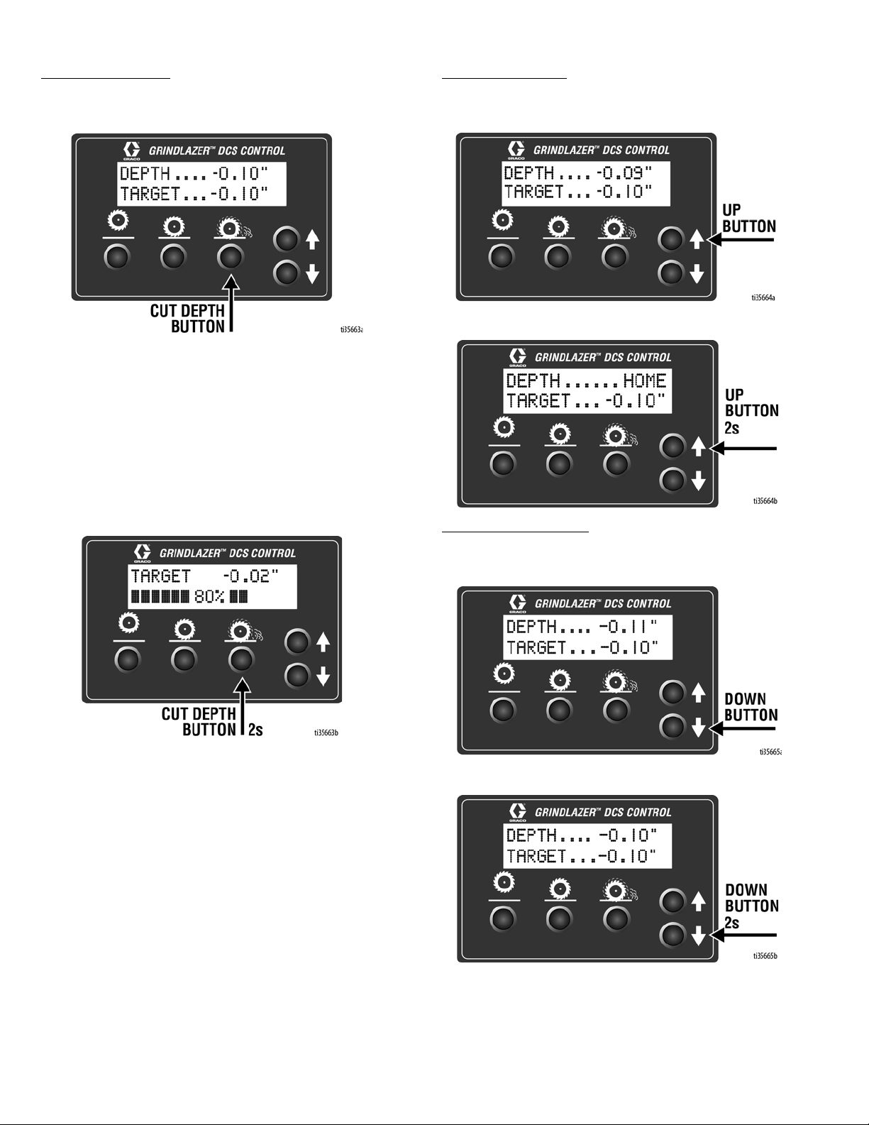
Cut Depth Button
Quick Press:
get.
Long Press:
- If at or above zero point: Opens new screen to
select desired cut depth using up/down buttons.
Takes the cutter head to the Cut Depth Tar-
•To exit without saving, quick press the Cut Depth
Button.
•To exit with saving, long press the Cut Depth Button.
Setup
Up Arrow Button*
Quick Press: Raises the cutter head by 0.01” (0.25mm,
10 mil).
Long Press: Raises the cutter head to Home position.
- If below zero point: Reprograms the Cut Depth Target to the current cutter head position.
Down Arrow Button*
Quick Press: Lowers the cutter head by 0.01” (25mm, 10
mil).
Long Press: Lowers the cutter head to Cut Depth Target.
*Handlebar Rocker Switch has the same functions as Up
and Down Arrow Buttons.
3A5581C 13
Page 14
Setup
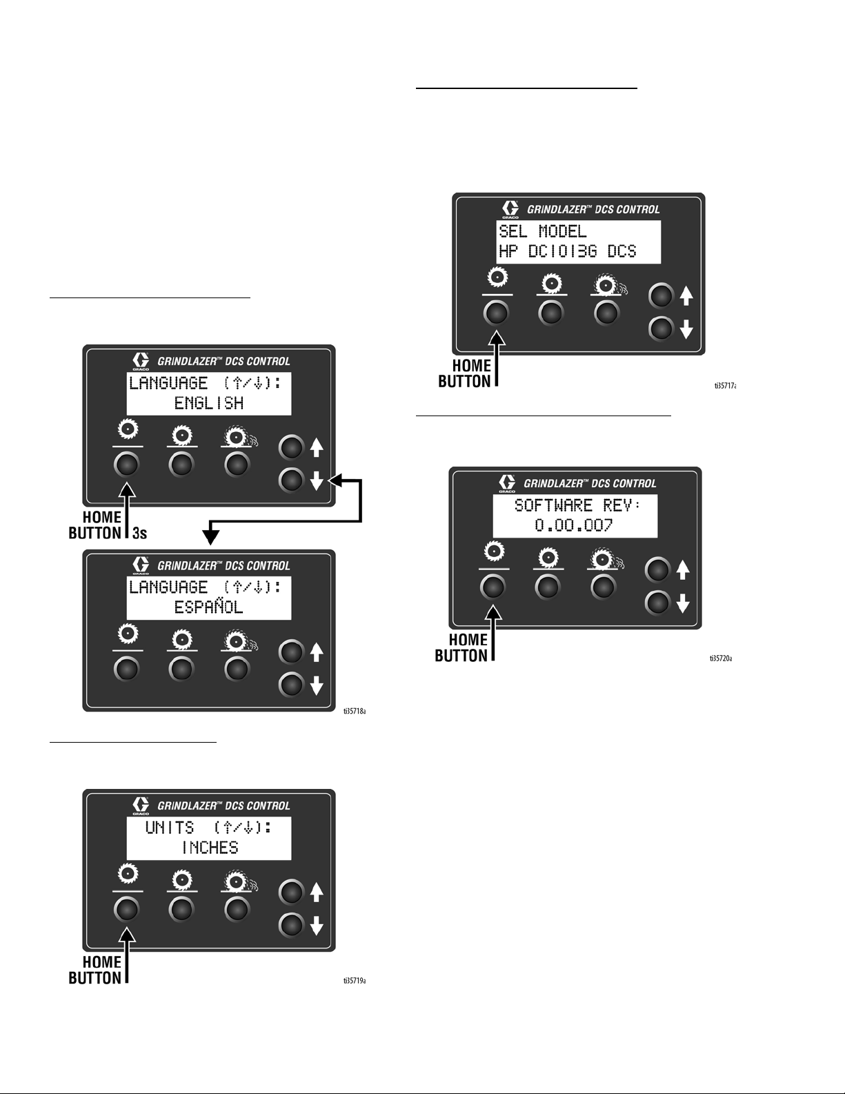
Menu Screens
To display the Menu Screens, hold down Home Button
from the Run Screen. To save menu settings and return
to Run Screen, hold down Home Button from any Menu
Screen.
To cycle through selections in each Menu Screen, use
Up and Down Arrow Buttons.
To advance to next Menu Screen, quick press the Home
Button.
Menu Screen #1 - Language
Select your desired language (English, Spanish,
French, German, or International Symbols).
Menu Screen #3 - Model Select
Your GrindLazer model name can be found on the handlebar dashboard label. Select the model on the DCS
Control which matches the model you have. This
ensures accurate depth readings. Hold down Up or
Down Arrow Buttons to cycle through models.
Menu Screen #4 - Software revision
Displays the revision of the software on the DCS Control.
Menu Screen #2 - Units
Select your desired depth units (inches, millimeters, or
mils).
14 3A5581C
Page 15

Setup
Menu Screen #5 - Error Codes
Displays the most recent error code and the total number of times that error has occured. Cycle through previous error codes using Up/Down Buttons.
Error Codes
E04: High Voltage
E05: High Motor Current
E08: Low Voltage
E09: Hall Sensor Error
E12: High Current (short circuit)
E31: Home Button Error
E32: Zero Button Error
E33: Cut Depth Button Error
E34: Up Button Error
E35: Down Button Error
To clear an error code that appears while on the Run
Screen:
1. Turn DCS Power Switch OFF.
2. Address/Fix the issue.
3. Turn DCS Power Switch ON.
NOTE: See Repair Manual for more information on
Error Codes and Troubleshooting.
3A5581C 15
Page 16
Operation
Operation
Do not start machine while cutter head is in contact
with the ground. Doing so can cause the operator to
lose control of the machine, resulting in property
damage and/or personal injury.
Machine Start Up
Before starting engine, perform the following:
• Read and understand engine manual.
• Make sure all guards are in place and secure.
• Make sure all mechanical fasteners are secure.
• Inspect for damage to engine and other exterior
surfaces.
• Inspect work area to locate any pipes, columns,
deck inserts, or other objects protruding from work
surface. Avoid these objects during operation.
Starting the Engine
• Connect Engine Kill Button Cord to operator and
machine.
• Open the fuel shut off on the gas tank and then
place the throttle lever at the “fast idle” position.
• Move the choke to closed.
• Push the Electric Start Engine Switch to start the
engine.
• After the engine starts, move choke to open.
• Set throttle to desired setting.
If the Engine Does Not Start
• Check engine for proper gas level.
• Check the spark plug. Make sure socket areas are
clean and clear of debris, and the proper gap is set.
Replace if needed.
• Battery might be dead. Try pulling the starter cord.
• Engine may have tilted backwards. If so, allow oil to
drain after removing spark plug.
• If engine still does not start, refer to the engine
manual.
• The engine will not start without the Corded Engine
Kill Clip securely in place.
16 3A5581C
Page 17
Operation
C
B
A
Cutting Material
Maintain a safe operating distance from other people
in the work area. Avoid any pipes, columns, openings,
or any other objects protruding from your work surface.
1. Start Engine, see page 16.
2. Turn vacuum on, if using a vacuum.
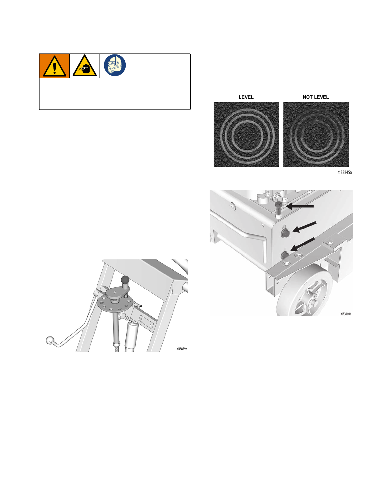
Adjusting Cutter Head Angle
1. Locate a level surface for cutter adjustment. All four
wheels should be on a level surface for setup.
2. Run at about 1/3 engine throttle.
3. Non-DCS Models: Lower the Cutter Head Engage
Lever.
5. Move the machine away from the current position to
inspect the cut. Use the elevation screws in the front
of the machine to pitch the cutter to the correct
plane to create the desired cut pattern. Loosen bolts
A and B, then adjust bolt C to modify the cutter head
angle. Tighten bolts A and B when the desired
cutter angle is achieved.
4. Non-DCS Models: Slowly lower the Cutter Head
Adjustment Dial and at first sign of dust from the
cutters, raise the depth control knob up a couple of
turns and then lift the Cutter Head Engage Lever
back up.
DCS Models: Slowly lower the cutter head by pressing
the Down Button on the DCS Control repeatedly until the
first sign of dust from the cutters. Then raise the cutter
head off of the surface by pressing the Home Button.
3A5581C 17
Page 18
Operation
Max
Min
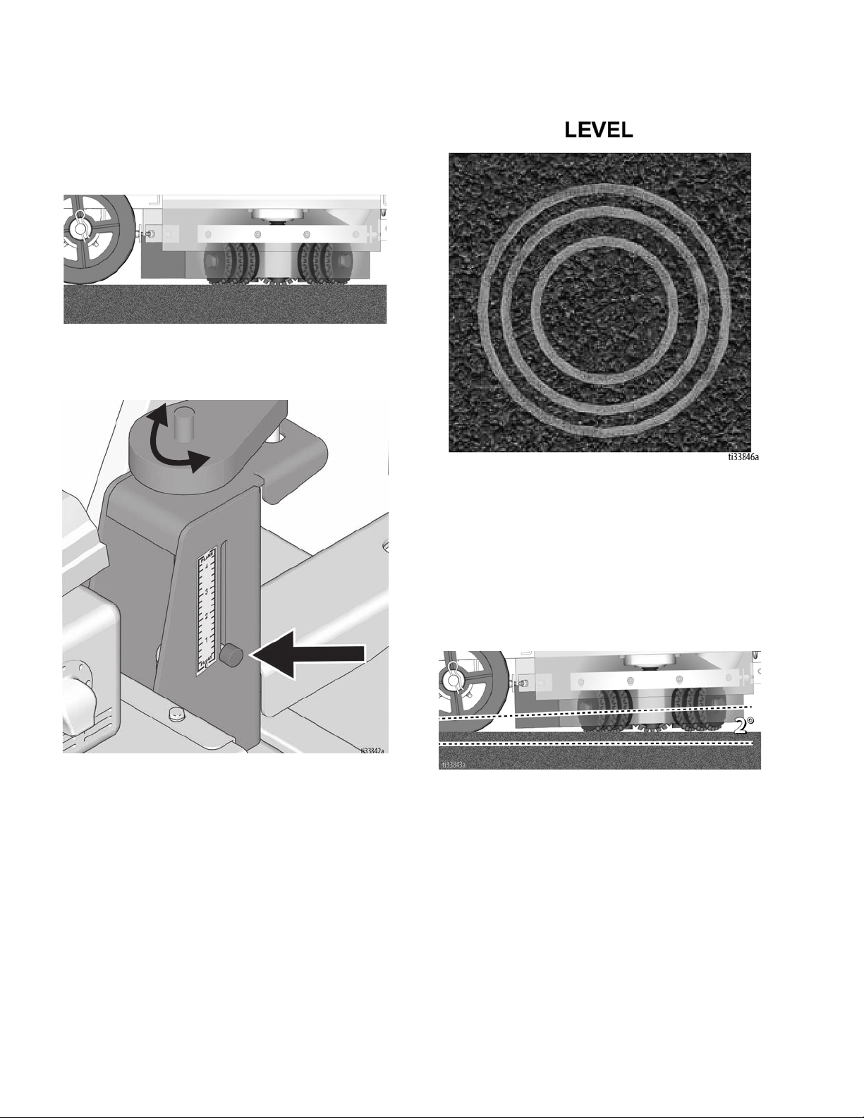
Concrete Cutting Setup
The machine set-up required when cutting
concrete is as follows:
1. Cutters should be parallel to the ground when
engaged.
2. Use the Pressure Control Dial to set the Pressure
Indicator to 0-1.
3. The cutting mark left by the machine should be an
even circle.
4. If the mark left by the machine is not as shown, adjust
the elevation screws accordingly. See page 17.
Asphalt Cutting Setup
The machine set-up required when cutting
asphalt is as follows:
1. Cutters should be at an angle no more than 2
degrees to the ground when engaged.
18 3A5581C
Page 19

Operation
2. Use the Pressure Control Dial to set the Pressure
Indicator to 2-3.
Cutting Technique
These are recommended settings only. Increasing
spring tension, depth of cut and pitch will increase the
removal speed at the expense of reduced life and
surface finish.
NOTICE
Care must always be taken to lift up the rotating
heads over any significant obstruction, including steel
or concrete expansion joints that can cause the cutters or spindle components to break.
NOTICE
NOTICE
Should you desire to tilt the machine, always tilt
forward. Tilting the machine backwards at any time
will flood the spark plug with oil and may cause
damage to your engine.
NOTE: On harder surfaces, it may be best to make
several passes in increments of 1/32 in. (0.8 mm) to get
to the desired depth.
3. The cutting mark left by the machine should be an
uneven circle.
4. If the mark is in the wrong direction, adjust the
elevation screws to pitch the cutter head to the
correct plane. See page 17.
• Make certain that the cutter head is positioned to
where only the cutter tips strike the surface.
• The cutter head will not withstand substrate contact.
NOTE: Contacting the removal surface too deeply
will cause premature wear to the cutter head and
other components. The correct depth setting is
indicated by relatively little machine vibration.
• Cutting too deep only has negative results. Try to
remove materials in several passes rather than one,
deep pass. Several tests will show the best, most
appropriate cutter impact. Use a forward, backward
and/or circular pattern to achieve your desired
finish.
NOTE: Positioning the machine over the surface in
many directions, as well as dialing the hand wheel up or
down can help create desirable surface patterns. After
several hours of practice, the operator will become
comfortable and should be able to remove materials
faster with enhanced results.
NOTE: The engine should not labor. Run engine at full
speed and adjust the forward speed to fit the work being
performed. Harder concrete surfaces will have to be cut
at a slower pace than asphalt or other softer surfaces.
3A5581C 19
Page 20

Operation
Stop Cutting Material
1. Non-DCS Models: Raise Cutter Head Engage
Lever so that the cutter head is off the ground.
2. Adjust Engine Throttle to low setting.
3. Depress Engine Kill Button.
DCS Models: Press the Home Button on the DCS
Control.
4. Clean the entire exterior of the machine after it has
cooled. Check for worn or damaged parts and
perform any required Maintenance on page 23.
20 3A5581C
Page 21

Operation
DCS Instructions
Each time the DCS Control is turned on, the DCS actuator will travel to the Home position.
Once the DCS Control finds Home, ensure the correct
model is selected as well as your desired language and
units. See Menu Screens, page 14, for instructions on
changing these settings.
Set Zero Point:
With the engine on, lower the cutter head by pressing
the Down Arrow Button until you hear the cutters make
contact with the pavement surface. Hold down the Zero
Button for 2 seconds. Your Zero Point has now been
saved.
NOTE: The Cut Depth Target is based off of the Zero
Point. Re-program the Zero Point if the cutter head is
changed or worn.
Set Cut Depth Target:
Quick press the Zero Button to take the cutter head to
the pavement surface. Set the Cut Depth Target by:
1. Quick pressing the Down Arrow Button as many
times as needed to achieve your target. Then long
press the Cut Depth Button to save your target.
NOTE: This method will lower the cutter head into
the pavement surface as you set your cut depth.
OR
2. From the Zero Point, long press the Cut Depth Button until a new screen pops up. Use the Down
Arrow Button to enter your Cut Depth Target. Then
long press the Cut Depth Button to save your target
and return to the Run Screen.
NOTE: This method will keep the cutter head stationary as you set your Cut Depth Target.
3A5581C 21
Page 22

Operation
The DCS Control is now ready to grind/scarify. Long
press down on the Handlebar Rocker Switch to lower
the cutter head to your Cut Depth Target. Short press up
or down on the switch to adjust your Cut Depth on the
fly. When finished with your cut, long press up on the
switch to raise the cutter head to the Home position.
NOTE: The Zero Point and Cut Depth are referenced
from the Home position. Recalibrate your DCS Control
periodically by pressing the Home button or long pressing up on the Handlebar Rocker Switch.
NOTE: Pressing any button while the cutter head is
moving to Zero or Cut Depth will stop the command and
halt the cutter head from moving any further up or down
until another button is pressed.
Manual Height Adjustment
If the DCS Control is not usable (dead battery, etc.), the
cutter head height can be adjusted using the Manual
Height Adjustment feature.
1. Remove fuse from fuse holder near positive battery
terminal. This will protect the battery from damage.
3. Insert 6mm hex key into the port the screw plug was
removed from.
- One revolution of the hex key results in 0.10”
(2.5mm, 100 mil) of adjustment at the cutter
head.
- Rotate counterclockwise to lower the cutter
head cutter head; rotate clockwise to raise the
cutter head. Max rotation speed of 1 revolu-
tion per second. Do not use power tools in
the Manual Height Adjustment port.
4. Once the desired depth is achieved, replace the
screw plug in order to keep water and dust out.
2. Use a 6mm hex key to remove the screw plug on
the top of the linear actuator.
22 3A5581C
Page 23

Maintenance
Avoid touching engine and cutter head after use until
they have completely cooled. To avoid injury from
unexpected start up, disconnect spark plug wire and
black battery cable before you service your unit.
The following steps should be performed to maintain
proper operation and sustain the life of the GrindLazer.
Maintenance
AFTER THE FIRST 20 HOURS OF
OPERATION:
• Drain engine oil and refill with clean oil. See engine
manual for correct viscosity.
EVERY 40-50 HOURS OF OPERATION:
• Change engine oil (see engine manual).
• Grease wheel bearings.
BEFORE OPERATION:
• Visually inspect the entire unit for damage or loose
connections.
• Check engine oil (see engine manual).
• Check bushings and cutters.
• Check cutter for uneven wear.
DAILY:
• Check all fasteners and re-tighten.
• Clean dust and debris from exterior of unit (do NOT
use pressure washer or other high pressure
cleaning equipment).
• Inspect dust skirts for damage. Repair or replace
damaged skirts in order to help dust and debris
containment.
• Check engine oil level and fill as necessary.
• Check and fill gas tank.
• Remove air filter cover and clean element. Replace
element if necessary. Replacement elements can
be purchased from your local engine dealer.
AS REQUIRED:
• Check drive belt and tension and tighten or replace
as needed.
For additional information about engine maintenance,
see engine manual.
• Grease the Cutter Head Engage Lever and lower
linkage (non-DCS models only).
3A5581C 23
Page 24

DCS Control Translations (DCS Models only)
DCS Control Translations (DCS Models only)
English Español Français Deutsche International
FINDING HOME ENCONTRANDO INICIO
HOME INICIO
DEPTH ALTURA
TARGET OBJETIVO
ZERO CERO
TROUVER LE DÉBUT
DÉBUT
HAUTEUR
OBJECTIF
ZÉRO
START FINDEN
START
TIEFE
ZIEL
NULL
SEL MODEL MODELO
LANGUAGE IDIOMA
UNITS UNIDAD DE MEDIDA
INCHES PULGADAS
MILLIMETERS MILIMETROS
MILS MILS
SOFTWARE REV SOFTWARE REV
ERROR ERROR
MODELE
LA LANGUE
UNITÉ DE MESURE
POUCES
MILLIMETRES
MILS
REVUE SOFTWARE
ERREUR
MODELL
SPRACHE
MAßEINHEIT
ZOLL
MILLIMETER
MILS
SOFTWARE REV
FEHLER
INCH
MM
MIL
24 3A5581C
Page 25

DCS Control Translations (DCS Models only)
English Español Français Deutsche International
FREQUENCY FRECUENCIA
HIGH CURRENT ALTA CORRIENTE
LOW VOLTAGE BAJO VOLTAJE
HIGH VOLTAGE ALTO VOLTAJE
HALL SENSORS SENSORES DE HALL
HOME BUTTON BOTÓN DE INICIO
FRÉQUENCE
COURANT ÉLEVÉ
BASSE TENSION
HAUTE TENSION
CAPTEURS DE HALL
BOUTON DE DÉBUT
ANZHAL
HOHER STROM
NIEDERSPANNUNG
HOCHSPANNUNG
HALL-SENSOREN
START KNOPF
ZERO BUTTON BOTÓN CERO
CUT BUTTON BOTÓN DE CORTAR
UP BUTTON BOTÓN ARRIBA
DOWN BUTTON BOTÓN DE ABAJO
BOUTON ZÉRO
BOUTON DE COUPE
BOUTON HAUT
BOUTON BAS
NULLTASTE
SCHNITT TASTE
NACH OBEN TASTE
NACH UNTEN TASTE
3A5581C 25
Page 26

Repair
Max
Min
Repair
Belt Replacement and Adjustment
To avoid injury from unexpected start up, disconnect
spark plug wire and black battery cable before you
service your unit.
1. Remove Clevis Pin.
2. Non-DCS Models: Rotate Cutter Head Engage
Lever to upwards position to release lower linkage
from inner frame.
3. Use the Pressure Control Dial to set the Pressure
Indicator to 0. This releases tension from the
pressure control spring.
DCS Models: Press Home Button on the DCS Control.
4. Unhook spring from the spring plunger (bottom rear
section of machine).
26 3A5581C
Page 27

Repair
5. Remove belt guards using a 7/16” socket or wrench.
8. To tighten belts, reverse step 6 until desired tension
is achieved.
Drive Pulley Replacement
1. After the belts have been removed, remove the 3
hex bolts using a 7/16” socket.
2. Screw those 3 hex bolts into the threaded holes
shown below and turn equally to remove pulley from
bushing.
6. Unscrew tension bolt using a 9/16” socket or wrench
until belts are loose (do not remove entirely).
7. At this point the belts should be loose enough to be
removed and replaced.
3. To remove bushing, use 1/8” hex key to loosen the
set screw.
***RECOMMENDED***
Use medium strength thread locker or equivalent on set
screws when reinstalling bushing.
3A5581C 27
Page 28

Repair
Engine Pulley Replacement
1. Remove the lock nuts that hold the engine plate to
the inner frame using a 9/16” socket or wrench.
2. Lift the engine off the machine.
3. Remove the hex bolt below the pulley using the 5/8”
socket, followed by the set screws using the 5/32”
hex key.
4. When reinstalling, adjust the pulley so that the
distance between the bottom face of the engine
plate and the uppermost edge of the V-belt groove
is 2 inches.
***RECOMMENDED***
Use medium strength thread locker or equivalent on set
screws when reinstalling pulley.
28 3A5581C
Page 29

Troubleshooting
To avoid injury from unexpected start up, disconnect
spark plug wire and black battery cable before you
service your unit.
Problem Cause Solution
Cutter head is too low Raise the cutter head
Cutters wearing unevenly/prematurely
Cutters Shaft Breakage
unevenly/prematurely
Material build up Clean the cutters
Bearings may be worn Replace bearings
Wrong cutters for application Contact Tech Services
Cutter head is too low Raise the cutter head
Over 40 hours service life Replace shafts
Troubleshooting
Excess Vibration
Machine jumps erratically
Drive belt wearing prematurely
Cutter Head Engage Lever will not
raise/lower (non-DCS models
only)
Cutter Head Adjustment Dial will
not turn (non-DCS models only)
Bearings may be worn Replace bearings
Drive shaft worn Replace drive shaft
Improper cutter set-up Contact Tech Services
Spindle contacting the ground Raise the cutter head
Wheels worn out Replace the wheels
RPM is too low Turn engine throttle to highest setting
Surface is severely uneven Move to smoother surface
Pulley is misaligned Re-align pulley, see
Engine Pulley Replacement, page 28
Wrong belt Order new belt
Cutter Head Adjustment Dial is set too high
or low
Threads are not greased Clean and grease threads
Linkage may be bent Replace linkage
Cutter Head Adjustment Dial may be out of
position
Raise or lower the Cutter Head Adjustment
Dial
Raise or lower cutter head adjustment dial
3A5581C 29
Page 30

Troubleshooting
DCS Models only
Problem Cause Solution
DCS Control not turning onBlown fuse on DCS Power wire. Replace fuse on DCS Power wire.
Power Switch is OFF or damaged. Turn Power Switch ON. Replace Power
Switch if damged.
Battery is dead. Charge Battery.
DCS Control Board is damaged. Replace DCS Control Board.
DCS Control runs for
short time, then turns off
DCS Control is on, but
actutator and/or cutter
head housing does not
move
Engine is not charging the battery. Battery voltage is
14.0-15.0 VDC when engine is full throttle and
charging correctly.
Actuator is disconnected from DCS Control. Check all connections.
A DCS Control Switch is pressed or defective. Ensure all switches are not stuck. Replace
Actuator rod is stuck. Manually move the actuator rod using the
Check engine charging coil and voltage rectifier/regulator. Replace or repair if needed.
switches if defective.
Manual Height Adjustment feature. Remove
screw plug on top of the actuator, then use
6mm hex key to move the rod.
DCS display does not
match Cut Depth.
DCS Control Buttons
work, but display is
blank
Actuator or DCS Control Board is damaged. See flow chart, page 33.
Battery is low. Charge battery.
DCS Control needs to recalibrate its position. Restart the DCS Control.
Zero Position is not set to the pavemet surface. Reprogram the Zero Position. See DCS
Instructions, page 21.
The wrong GrindLazer model is selected on the DCS
Control.
The display is unplugged or damaged. Check that the display ribbon cable and
Select the correct model on DCS Control.
See Menu Screens, page 14.
red/white wire are connected inside Control
Box. Replace if damaged.
30 3A5581C
Page 31

DCS Error Codes
To clear an error code on the DCS Control: 1. Turn DCS Power Switch to OFF.
2. Address/Fix the issue.
3. Turn DCS Power Switch to ON.
Error Cause Solution
Troubleshooting
E04: High Voltage
(20VDC or greater, measured across battery
posts)
E05: High Motor Current (15 Amps or
greater, measured on
blue or brown actuator
wire)
E08: Low Voltage
(7VDC or lower, measured across battery
posts)
E09: Hall Sensor Error Actuator Signal Cable is disconnected from DCS
E12: High Current (short
circuit, 60 amps or
greater, measured on
red or black wire
between battery and
DCS Control)
E31: Home Button Error The Home Button is stuck or shorted. Check to see if Home Button is stuck. If not
E32: Zero Button Error The Zero Button is stuck or shorted. Check to see if Zero Button is stuck. If not
Battery is damaged. Replace battery.
Engine voltage rectifier/regulator is damaged. Replace engine voltage rectifier/regulator.
Actuator rod is stuck. Manually move the actuator rod using the
Manual Height Adjustment feature.
Too high of load. Ensure there is no binding anywhere on the
unit when the actuator is moving.
Battery is low/dead. Charge battery.
Engine is not charging the battery. Check the engine charging coil and voltage
rectifier/regulator. Replace or repair if
needed.
Check all connections. Repair or replace if
Control or is damaged.
Actuator or DCS Control Board is damaged. See flow chart, page 33.
A wire or board component has shorted. Check all wires for shorts. If all wires are
needed.
okay, the DCS Control board may be damaged and need to be replaced.
stuck, replace the Home Button switch.
stuck, replace the Zero Button switch.
E33: Cut Depth Button
Error
3A5581C 31
The Cut Depth Button Error is stuck or shorted. Check to see if Cut Depth Button is stuck. If
not stuck, replace the Cut Depth Button
switch.
Page 32

Troubleshooting
Error Cause Solution
E34: Up Button Error The Up Button or Handlebar Rocker Switch is stuck
or shorted.
E35: Down Button Error The Down Button or Handlebar Switch is stuck or
shorted.
Disconnect Handlebar Rocker Switch from
the DCS Control. Clear the error code.
If the error code reappears 30 seconds
after turning the Power Switch back ON,
the problem is the Up Button on the DCS
Control. Check to see if the Up Button is
stuck. If not stuck, replace the Up Button
Switch.
If the error code does not reappear 30
seconds after turning the Power Switch
back ON, the problem is the Handlebar
Rocker Switch. Check to see if the switch
is stuck. If not stuck, replace the Handlebar Rocker Switch.
Disconnect Handlebar Rocker Switch from
the DCS Control. Clear the error code.
If the error code reappears 30 seconds
after turning the Power Switch back ON,
the problem is the Down Button on the
DCS Control. Check to see if the Down
Button is stuck. If not stuck, replace the
Down Button Switch.
If the error code does not reappear 30
seconds after turning the Power Switch
back ON, the problem is the Handlebar
Rocker Switch. Check to see if the switch
is stuck. If not stuck, replace the Handlebar Rocker Switch.
32 3A5581C
Page 33

DCS Actuator Rod Does Not Move
YES NO
Turn power switch to OFF. Remove the blue shroud behind the DCS Control.
Ensure you have a good 12V battery installed. Disconnect the actuator motor
wires and signal cable from the DCS Control. Connect a multimeter between
the blue and brown wires on the DCS Control. Turn the power switch to ON.
Measure the voltage (DC) within 10 seconds of turning the power on. Does it
measure at least 3.0 VDC?
Connect the blue and brown wires on the
actuator to a good 12VDC battery. First try with
the blue wire on positive post and brown wire
on negative post. If the actuator rod does not
move, put the blue wire on the negative post
and the brown wire on the positive post. Does
the rod move in either case?
REPLACE
ACTUATOR
REPLACE
ACTUATOR
REPLACE DCS
CONTROL BOARD
REPLACE DCS
CONTROL BOARD
NO
NO
NO
YES
Within 10 seconds of turning the power switch to ON (while connected to
a good battery), measure the voltage (DC) between the red and black
wires on the actuator signal cable coming from the DCS Control. Does it
measure at least 10 VDC?
Reconnect the actuator motor wires and signal cable from the actuator to
the DCS Control. Turn the power switch to ON. Does the DCS Control
display the Run Screen within 5 seconds?
YES
YES
BLUE
BROWN
12V
Use this flow chart if the DCS Actuator Rod does not
move or if the DCS displays error code E09 (Hall Sensor
Error). Reference Wiring Diagram, page 54.
Troubleshooting
ti36057a
3A5581C 33
Page 34

Parts
*Use industry standard torques when not specified.
Ref. Torque
20-22 ft-lb (27.1-30.0 N•m)
72-84 in-lb (8.1-9.5 N•m)
1
2
2
1
Parts
Outer Frame Assembly - 25M847
34 3A5581C
Page 35

Outer Frame Assembly Parts List - 25M847
Item: P/N Description Qty
1 17W049 Ball Knob 2
2 17Y998 Handwheel Assembly 1
3 17W111 Spring 1
4 17W119 Locater Pin 1
5 17W127 E-Clip 1
6 17W054 Thrust Bearing 1
7 17W105 5/8” Structural Washer 2
8 17Y022 Upper Linkage 1
9 119563 5/8” Belleville Spring Washer 2
10 17W113 Bronze Washer 2
11 C19075 5/8-11x2.5” Hex Head Bolt 1
12 17W056 Locking Collar 1
13 17W045 Grease Fitting, straight 2
14 17Y114 Lower Linkage 1
15 17W217 Pin Detent 1
16 17W243 Damper Kit 1
17 17W230 Spring Plunger 1
18 17W185 Outer Frame 1
19 17W189 Caster Wheel 2
20 17W234 3/4-10 Jam Nut 6
21 17W261 3/4-10 Nylon Nut 2
22 17W186 Weight 2
23 100023 3/8” Flat Washer 8
24 100003 3/8-16x1.5” Hex Head Bolt 4
25 101566 3/8-16 Nylon Nut 4
26 17W302 Height Control Lever Sheathing 1ft
29
16C393 Warning Label, Foot Cut 2
30
16D646 Warning Label, Hot Surface 2
31 15H108 Warning Label, Pinch 2
32 194126 Warning Label, Fire and Explosion 1
33
17W264 Warning Label, Multiple 1
34 16C394 Warning Label, Entanglement 2
35 17W284 Tachometer (not shown) 1
Replacement warning, safety labels, tags, and cards are
available at no cost.
Parts
3A5581C 35
Page 36

Parts
*Use industry standard torques when not specified.
Ref. Torque
72-84 in-lb (8.1-9.5 N•m)
1
1
Shock Assembly - 25M847
Shock Assembly Parts List
Item: P/N Description Qty
1 17W247 Upper Shock Mount Clamp 1
2 17W246 Upper Shock Mount Bracket 1
3 17W248 1/4-20x2.25” Hex Cap Screw 4
4 17W020 1/4” Flat Washer 8
5 17W126 Shock Absorber 1
36 3A5581C
6 17W125 3/8-16x1.5” Hex Cap Screw 1
7 100023 3/8 Flat Washer 2
8 17W123 Lower Shock Mounting Bracket 1
9 101566 3/8-16 Nylon Nut 1
10 102040 1/4” Nylon Nut 4
Page 37

Adjustable Handles - 25M847
*Use industry standard torques when not specified.
Ref. Torque
20-22 in-lb (27.1-30.0 N•m)
1
1
Parts
Adjustable Handles Parts List - 25M847
Item: P/N Description Qty
1 100003 3/8-16x1.5” Hex Cap Screw 4
2 100133 3/8” Lock Washer 4
3 120454 5/16” Flat Washer 4
4 17W003 Handle Clamps 4
5 17W268 3/16 x 1-1/4 Roll Pin 2
6 17W216 Adjustable Handle Bars 2
7 17W195 Long Handle Bar Grips (24” Long) 2
8 17W269 Short Handle Bar Grips (4.5” Long) 2
9 17W009 Small Black Tube Caps 4
3A5581C 37
Page 38

Parts
Ref. Torque
20-22 in-lb (27.1-30.0 N•m)
72-84 in-lb (8.1-9.5 N•m)
1
2
25M847 (Series B)
25N669
Adjustable Handles - 25M847 (Series B) & 25N669
38 3A5581C
Page 39

Adjustable Handles Parts List - 25M847 (Series B)
Item: P/N Description Qty
1 17Y113 Cable, Vernier Control 1
2 18A137 Starter Assembly 1
3 18A143 Kill Switch Assembly 1
4 18A133 Tachometer Assembly 1
5 17W269 Grip, Foam, Handlebar, 4.5” 2
6 17W003 Clamp, Handlebar Locking 4
7 100003 Screw, Cap, Hex Head, 3/8-16x1.5” 4
8 100133 Washer, Lock, 3/8” 4
9 120454 Washer, Flat, 5/16” 4
10 17W268 Pin, Roll, 3/16” DIA x 1-1/4” 2
11 18A331 Handle, Adjustment, Bar, right 1
12 17W216 Handle, Adjustment, Bar, left 1
13 17W195 Grip, Foam, Handlebar, 24” 2
14 17W009 Plug, Cap, 3/4” 4
15
17W264 Warning Label, Multiple 1
Replacement warning, safety labels, tags, and cards are
available at no cost.
Parts
Adjustable Handles Parts List - 25N669
Item: P/N Description Qty
1 17Y113 Cable, Vernier Control 1
2 18A137 Starter Assembly 1
3 18A143 Kill Switch Assembly 1
4 18A142 Power Switch Assembly 1
5 18A133 Tachometer Assembly 1
6 17W269 Grip, Foam, Handlebar, 4.5” 2
7 17W003 Clamp, Handlebar Locking 4
8 100003 Screw, Cap, Hex Head, 3/8-16x1.5” 4
9 100133 Washer, Lock, 3/8” 4
10 120454 Washer, Flat, 5/16” 4
11 17W268 Pin, Roll, 3/16” DIA x 1-1/4” 2
12 18A331 Handle, Adjustment, Bar, right 1
13 17W216 Handle, Adjustment, Bar, left 1
14 17W195 Grip, Foam, Handlebar, 24” 1
15 18A424 Grip, Foam, Handlebar, 23” 1
16 17Y120 Housing, control switch 1
17 17Y999 Switch, Rocker 1
18 17W009 Plug, Cap, 3/4” 3
19
17Y160 Warning Label, Multiple 1
Replacement warning, safety labels, tags, and cards are
available at no cost.
3A5581C 39
Page 40

Parts
*Use industry standard torques when not specified.
Ref. Torque
28-30 ft-lb (38.0-40.0 N•m)
144-180 in-lb (16.2-20.0 N•m)
72-84 in-lb (8.1-9.5 N•m)
123
2
3
3
2
2
1
3
Drive System Assembly - 25M847
40 3A5581C
Page 41

Drive System Parts List - 25M847
Item: P/N Description Qty
1 17W089 Hex Slotted Screw - Self Tapping 2
2 17X251 Throttle Cable Assembly 1
3 17W143 #10 Flat Washer 2
4 17W262 #10-32 Nylon Nut 2
5 17W194 13HP Engine 1
6 110838 5/16” - 18 Nylon Nut 2
7 120454 5/16” - Flat Washer 6
8 17W211 Engine Pulley 1
9 17W088 Key for Engine Pulley 1
10 17W212 Drive Pulley 1
11 17W213 Bushing for Drive Pulley 1
12 17W146 7/16” Fender Washer 1
13 17X252 Key for Drive Pulley 1
14 116645 7/16-20x1” Hex Head Bolt 1
15 17W210 Drive Belt 2
16 17W057 1/2-20x4” Hex Head Bolt 4
17 101566 3/8-16 Nylon Nut 4
18 100023 3/8” Flat Washer 4
19 17W218 1/2” Hardened Spacer 8
20 17W191 Engine Mount Plate 1
21 17W238 Driveshaft Housing Assembly 1
22 108843 6/16-18x1 3/4” Hex Head Bolt 2
23 17W197 Rubber Bushing 4
24 17W193 Engine Mount Spacer 2
25 100214 5/16” Lock Washer 2
26 109031 5/16”-24x1” Hex Head Bolt 2
27 17W220 Cap Plug 1
28 17W175 Inner Frame 1
29 17W192 Engine Tensioner 1
30 17W183 Cutter Head Guard 1
31 17W222 Skirt Retainer (med) 1
32 17W223 Skirt Retainer (small) 2
33 17W184 Rubber Skirt 1
34 17W224 Skirt Retainer (large) 3
35 17W020 1/4” Flat Washer 18
36 102040 1/4-20 Nylock Nut 18
37 107139 1/4-20x1” Carriage Bolt 18
38 101926 1/2-20 Nylock Nut 4
40* 17W029 Deflector for Engine 1
41 17W964 Self Tapping Screws for Deflector 3
* Not Shown
Parts
3A5581C 41
Page 42

Parts
*Use industry standard torques when not specified.
Ref. Torque
28-30 ft-lb (38.0-40.0 N•m)
144-180 in-lb (16.2-20.0 N•m)
72-84 in-lb (8.1-9.5 N•m)
123
Drive System Assembly - 25M847 (Series B) & 25N669
42 3A5581C
Page 43

Drive System Parts List - 25M847 (Series B) & 25N669
Parts
Item: P/N Description Qty
1 18A394 Frame, Inner 1
2 17W235 Bearing, Axle, Ball, 1” 2
3 17W232 Shaft, Axle, Front 1
4 17W187 Holder, Axle, Front 2
5 17W190 Wheel, Front, 8 x 2-5/8 x 3/4 2
6 17W238 Bearing, Assembly, Drive Shaft 1
7 120454 Washer, Flat, 5/16” 6
8 110838 Nut, Lock, 5/16”-18 2
9 17Y158 Grommet, push in 1
10 17W220 Plug, Cap, 3” 1
11 558673 Screw, cap, socket head, 5/16-18 x
0.75”
12 17W188 Spacer, Axle, Front 2
13 169468 Washer, Flat, 3/4” 2
14 17W226 Shim, 3/4” ID x 1-1/2” OD x .048”
THK
15 17W229 Pin, Cotter, Hitch 2
16 100023 Washer, Flat, 3/8” 4
17 17W223 Screw, Cap, Hex Head, 1/2-13 x 1.5” 4
18 17W098 Washer, Flat, 1/2” 4
19 101911 Washer, Lock, 1/2” 4
20 17W215 Screw, Cap, Hex Head, 1/2-13 x 3 2
21 555395 Nut, Hex, 1/2-13 2
22 17W195 Screw, Cap, Hex Head, 3/8-16 x 3 1
23 101566 Nut, Lock, 3/8”-16 4
24 17W192 Belt, Tensioner, engine 1
25 17W193 Spacer, Engine, Mount 2
26 17W197 Grommet, Rubber 4
27 17W191 Plate, Engine, Mount 1
28 17W194 Engine, Honda GX390V, 13HP 1
2
4
29 108843 Screw, Cap, Hex Head, 5/16-18 x
30 17W183 Guard, Head Cutter 1
31 17W184 Gasket, Rubber, Skirt 1
32 17W222 Retainer, Medium 5-12”, Skirt 1
33 107139 Bolt, Round Head, 1/4 - 20 x 1” 18
34 17W020 Washer, flat, 1/4” 18
35 102040 Nut, Lock, 1/4”-20 18
36 17W223 Retainer, Small, 3-14”, Skirt 2
37 17W224 Retainer, Large, 12”, Skirt 3
38 17W057 Screw, Cap, Hex Head, 1/2-20 x 4” 4
39 17W218 Spacer, Hardened, 1/2” 8
40 101925 Nut, Lock, 1/2”-20 4
41 17X252 Key, Way, Drive Pulley 1
42 17W213 Bushing, 35mm Bore, w/ Key Slot 1
43 17W212 Pulley, Engine, 2-groove 1
44 109031 Screw, Cap, Hex Head 5/16 - 24x1” 2
45 100214 Washer, Lock, 5/16” 2
46 17W211 Pulley, Engine 1
47 17W088 Key, Drive, 1/4” SQ x 2-1/4” 1
48 16Y269 Washer, Flat, M12 3
49 17W146 Washer, Fender, 7/16” 1
50 100052 Washer, Lock, 7/16” 1
51 116645 Screw, Cap, Hex Head, 7/16-20x1” 1
52 17W210 Belt, Drive, Heavy-Duty 2
53
15H108 Warning Label, Pinch 2
54
194126 Warning Label, Fire & Explosion 1
Replacement warning, safety labels, tags, and cards are
available at no cost.
1.75”
2
3A5581C 43
Page 44

Parts
*Use industry standard torques when not specified.
Ref. Torque
28-30 ft-lb (38.0-40.0 N•m)
20-22 ft-lb (27.1-30.0 N•m)
144-180 in-lb (16.2-20.0 N•m)
72-84 in-lb (8.1-9.5 N•m)
123
4
2
3
1
4
4
1
4
Front Assembly - 25M847
44 3A5581C
Page 45

Front Assembly Parts List - 25M847
Item: P/N Description Qty
1 100022 1/4-20x3/4” Hex Head Bolt 4
2 100016 1/4” Lock Washer 4
3 17W020 1/4” Flat Washer 4
4 17W176 Belt Cover (top) 4
5 17W177 Belt Cover (back) 1
6 101712 5/8-11 Nylock Nut 1
7 17W049 Ball Knob 1
8 17W181 Handwheel 1
9 17W141 1/2-13x4” Socket Head Cap Screw 1
10 17W054 Thrust Bearing 1
11 17W105 5/8” Structural Washer 2
12 17W215 1/2-13x3” Hex Head Bolt (full thread) 2
13 555395 1/2-13 Hex Nut 2
14 17W196 3/8-16x3” Hex Head Bolt (full thread) 1
15 100023 3/8” Flat Washer 7
16 17W192 Belt Tension 1
17 17W232 Axle Shaft 1
18 558673 5/16-18x3/4” Socket Head Cap Screw 2
19 17W187 Axle Holder 2
20 17W229 Cotter Pin 2
21 17W188 Spacer 2
22 17W235 Axle Bearing 2
23 169468 3/4” Flat Washer 2
24 17W226 Shim 4
25 17W190 Front Wheel 2
26 17X253 5/16-18 Hex Nut 1
27 108843 5/16-18x1 3/4” Hex Head Bolt 1
28 17W056 Locking Collar 1
29 17W182 Pressure Control Linkage 1
30 17W221 Pressure Control Spring 1
31 17W098 1/2” Flat Washer 4
32 17W064 1/2” Lock Washer 4
33 17W233 1/2-13x1.5” Hex Head Bolt 4
34 17W231 3/8-16x3.5” Hex Head Bolt 4
35 100133 3/8” Lock Washer 4
36 17W237 Tapered Sleeve 1
Parts
3A5581C 45
Page 46

Parts
*Use industry standard torques when not specified.
Ref. Torque
28-30 ft-lb (38.0-40.0 N•m)
20-22 ft-lb (27.1-30.0 N•m)
144-180 in-lb (16.2-20.0 N•m)
72-84 in-lb (8.1-9.5 N•m)
123
4
Front Assembly - 25M847 (Series B) & 25N669
46 3A5581C
Page 47

Front Assembly Parts List - 25M847 (Series B) & 25N669
Parts
Item: P/N Description Qty
1 17Y118 Frame, Outer 1
2 17W189 Wheel, Caster 2
3 17W234 Nut, Jam, 3/4”-10 6
4 108540 Nut, Lock, 3/4”-10 2
5 17W186 Ballast, Weight 2
6 100003 Screw, Cap, Hex Head, 3/8-16 x 1.5” 4
7 100023 Washer, Flat, 3/8” 12
8 101566 Nut, Lock, 3/8”-16 6
9 17W230 Plunger, Spring 1
10 555396 Nut, Hex, 5/8”-11 1
11 17W181 Wheel, Hand, Large 1
12 17W182 Link, Pressure Control 1
13 17W056 Collar, Locking, 5/8” 1
14 17W105 5/8” Structural Washer 2
15 17W054 Bearing, Thrust 1
16 101712 Nut, Lock, 5/8”-11 1
17 17X254 Nut, Hex, 5/16”-18 1
18 108843 Screw, Cap, Hex Head, 1/4-20 x 0.75” 4
19 17W221 Spring, Control, Pressure 1
20 17W141 Screw, Cap, Socket Head, 1/2-13 x 4” 1
21 17W237 Sleeve, Tapered, Aluminum 1
22 17W049 Knob, Ball 1
23 17W176 Belt, Cover, Top 1
24 100022 Screw, Cap, Hex Head, 1/4-20 x 0.75” 4
25 100016 Washer, Lock, 1/4” 4
26 17W020 Washer, Flat, 1/4” 4
27 17W177 Belt, Cover, Back 1
28 17Y121 Box, Battery 1
29 18A435 Rubber, Backing Skirt 1
30 110823 1/4-20 x 1” Low Profile Screw 2
31 115753 Battery, 33AH, Sealed 1
35 100021 Screw, Cap, Hex Head, 1/4-20 x 1” 2
36 100015 Nut, Hex, 1/4”-20 2
37 17W231 Screw, Cap, Hex Head, 3/8-16 x 3.75” 4
38 100133 Washer, Lock, 3/8” 4
39 168117 3” x 1.5” Rectangular Plug 2
40 18A115 Support, Tubing 5
41 17W089 Screw, Self-Tap, 10-32 x 0.5” 5
42 17Y117 Bracket, Vernier Control 1
43 120454 Washer, Flat, 5/16” 4
44 113956 Bolt, Carriage, 3/8-16 x 1” 2
45 17W861 Label, Made in USA 1
46
16C394 Warning Label, Entanglement 2
47 16D646 Warning Label, ISO, Hot Surface 2
48
16C393 Warning Label, ISO, Cut Foot Hazard 2
49 17W751 Label, Pro Series 1
50 17W241 Label, Depth Control 1
51 17W263 Label, Pressure Control 1
52 17P925 Label, A+ Service 1
200 18Y704 Foam, 1/2”, under battery 1
201 18A786 Strap, velcro, 2” 1
202 18Y705 Foam, 1/4”, front of battery 1
203 18Y701
Foam,1/4”, side and back of battery
Replacement warning, safety labels, tags, and cards are
available at no cost.
3
3A5581C 47
Page 48

Parts
*Use industry standard torques when not specified.
Ref. Torque
28-30 ft-lb (38.0-40.0 N•m)
20-22 in-lb (2.3-2.5 N•m)
1
2
Controls Assembly - 25M847 (Series B)
48 3A5581C
Page 49

Controls Assembly Parts List - 25M847 (Series B)
Item: P/N Description Qty
1 17W108 Handle, Assembly, Cam Lever 1
2 17Y115 Bracket, Shock 1
3 120454 Washer, Flat, 5/16” 6
4 17W081 Screw, Cap, Hex Head, 5/16”-18 x 2.5” 4
5 110838 Nut, Lock, 5/16”-18 4
6 17W049 Knob, Ball 2
7 17W045 FItting, Grease 2
8 17Y822 Link, Upper 1
9 17W113 Washer, Flat, Bronze 2
10 119563 Washer, Belleville 2
11 C19075 Screw, Cap, Hex Head, 5/8-11 x 2.5” 1
12 M71149 Screw, Set, SCH, 10-32 x 0.25” 1
13 17Y998 Wheel, Assembly, Hand 1
14 17W119 Pin, Locator 1
15 17W127 Ring, Retainer 1
16 17W146 Washer, Fender, 7/16” 1
17 17W111 Spring, Compression 1
18 17W105 Washer, Structural, 5/8” 2
19 17W054 Bearing, Thrust 1
20 17W056 Collar, Locking, 5/8” 1
21 17Y114 Link, Lower 1
22 17W123 Link, Attachment, Lower 1
23 100023 Washer, Flat, 3/8” 2
24 17W125 Screw, Cap, Hex Head, 3/8-16 x 3.5” 1
25 101566 Nut, Lock, 3/8-16 1
26 17W126 Shock, Absorber 1
27 17W217 Pin, Detent 1
28 17Y116 Plate, Handlebar, Front 1
29 117501 Screw, Hex Washer Head, 8-32 x 0.5” 6
30 18A154 Cover, Backing 1
31 17W053 Label, Info, Control 1
32 17W240 Label, Brand 1
Parts
3A5581C 49
Page 50

Parts
*Use industry standard torques when not specified.
Ref. Torque
28-30 ft-lb (38.0-40.0 N•m)
20-22 in-lb (2.3-2.5 N•m)
1
2
Controls Assembly - 25N669
50 3A5581C
Page 51

Controls Assembly Parts List - 25N669
Item: P/N Description Qty
1 17Y112 Bracket, Control Mounting 1
2 17Y111 Bracket, Upper Linkage 1
3 120454 Washer, Flat, 5/16” 8
4 17W081 Screw, Cap, Hex Head, 5/16-18 x 2.5” 4
5 110838 Nut, Lock, 5/16’ 4
6 18A790 Control, Assembly, DCS 1
7 128990 Screw, Cap, Button Head, 10-32 x
0.75”
8 17W886 Washer, Flat, M6 4
9 115483 Nut, Lock, 10-32 4
10 17Y237 Actuator, Linear, 12V 1
11 18A114 Pin, Clevis 2
12 17Y962 Pin, Cotter, Bow Tie 2
13 17Y110 Bracket, Lower Linkage 1
14 17W217 Pin, Detent 1
15 18A151 Cover, Shroud 1
16 117501 Screw, Hex Washer Head, 6-32 x 0.5” 9
17 18A154 Cover, Backing 1
18 17Y823 Label, Brand 1
19 18A330 Label, Instruction 1
4
Parts
3A5581C 51
Page 52

Parts
Spindle Cutter Assembly (24 pin)
Spindle Cutter Assembly Parts List - 25N363
Item: P/N Description Qty
1* 17W324 Spindle Assembly 1
2 17X257 Rubber Bushing 6
3 17W258 Steel Bushing 3
4 17X259 Hub Connector 1
5 17X260 Hub Plate 1
6 17W299 Lock Washer 3
7 17W297 Hex Cap Screw 3
8 19A087 24 Pin Cutter (set of 3) 1
9 17W267 Backing Plate 3
10 17X266 Belleville Washer 3
11 17W265 Left Handed Hex Nut 3
* Item 1 includes items 1-7, 9-11
52 3A5581C
Page 53

DCS Control Box 18A790
25N669 only
DCS Control Box 18A790
Parts List
Ref. Part Description Qty.
300 18A690 KIT, DCS Control Box, machined
includes 300a - 300f
301 17Y686 LABEL, control, GrindLazer DCS
302 18A691 KIT, potted DCS Control PCB
303 18A692 KIT, display board, DCS control
3A5581C 53
Ref. Part Description Qty.
304 18A693 KIT, home button, DCS
1
305 18A694 KIT, zero button, DCS
1
306 18A695 KIT, cut cutton, DCS
1
307 18A696 KIT, up button, DCS
1
308 18A697 KIT, down button, DCS
1
1
1
1
1
Page 54

Wiring Diagram
17Y999
17Y237
18A790
Wiring Diagram
DCS System
54 3A5581C
Page 55

DCS Control Box
Powers Display
Wiring Diagram
3A5581C 55
Page 56

Technical Data
WARNING: This product can expose you to chemicals known to the State of California to cause cancer
and birth defects or other reproductive harm. For more information go to www.P65Warnings.ca.gov.
CALIFORNIA PROPOSITION 65
Technical Data
GrindLazer Pro RC813 G (25M847)
Noise level (dBa)
Sound power
Sound pressure
Vibration level*
Right/Left Hand
* Vibration measured per ISO 5349 based on 8 hr daily exposure
Dimensions/Weight (unpackaged) US Metric
Height 50 in. 127 cm
Length 48 in. 122 cm
Width 27 in. 69 cm
Weight 450 lb 204 kg
GrindLazer Pro RC813 G DCS (25N669)
Noise level (dBa)
Sound power
Sound pressure
Vibration level*
Right/Left Hand
* Vibration measured per ISO 5349 based on 8 hr daily exposure
Dimensions/Weight (unpackaged) US Metric
Height 50 in. 127 cm
Length 48 in. 122 cm
Width 27 in. 69 cm
Weight 475 lb 216 kg
109 dBa per ISO 3744
94 dBa measured at 3.1 feet (1m)
18.1 m/sec
109 dBa per ISO 3744
94 dBa measured at 3.1 feet (1m)
18.1 m/sec
2
2
56 3A5581C
Page 57

Graco Standard Warranty
Graco Standard Warranty
Graco warrants all equipment referenced in this document which is manufactured by Graco and bearing its name to be free from defects in
material and workmanship on the date of sale to the original purchaser for use. With the exception of any special, extended, or limited warranty
published by Graco, Graco will, for a period of twelve months from the date of sale, repair or replace any part of the equipment determined by
Graco to be defective. This warranty applies only when the equipment is installed, operated and maintained in accordance with Graco’s written
recommendations.
This warranty does not cover, and Graco shall not be liable for general wear and tear, or any malfunction, damage or wear caused by faulty
installation, misapplication, abrasion, corrosion, inadequate or improper maintenance, negligence, accident, tampering, or substitution of
non-Graco component parts. Nor shall Graco be liable for malfunction, damage or wear caused by the incompatibility of Graco equipment with
structures, accessories, equipment or materials not supplied by Graco, or the improper design, manufacture, installation, operation or
maintenance of structures, accessories, equipment or materials not supplied by Graco.
This warranty is conditioned upon the prepaid return of the equipment claimed to be defective to an authorized Graco distributor for verification of
the claimed defect. If the claimed defect is verified, Graco will repair or replace free of charge any defective parts. The equipment will be returned
to the original purchaser transportation prepaid. If inspection of the equipment does not disclose any defect in material or workmanship, repairs
will be made at a reasonable charge, which charges may include the costs of parts, labor, and transportation.
THIS WARRANTY IS EXCLUSIVE, AND IS IN LIEU OF ANY OTHER WARRANTIES, EXPRESS OR IMPLIED, INCLUDING BUT NOT
LIMITED TO WARRANTY OF MERCHANTABILITY OR WARRANTY OF FITNESS FOR A PARTICULAR PURPOSE.
Graco’s sole obligation and buyer’s sole remedy for any breach of warranty shall be as set forth above. The buyer agrees that no other remedy
(including, but not limited to, incidental or consequential damages for lost profits, lost sales, injury to person or property, or any other incidental or
consequential loss) shall be available. Any action for breach of warranty must be brought within two (2) years of the date of sale.
GRACO MAKES NO WARRANTY, AND DISCLAIMS ALL IMPLIED WARRANTIES OF MERCHANTABILITY AND FITNESS FOR A
PARTICULAR PURPOSE, IN CONNECTION WITH ACCESSORIES, EQUIPMENT, MATERIALS OR COMPONENTS SOLD BUT NOT
MANUFACTURED BY GRACO. These items sold, but not manufactured by Graco (such as electric motors, switches, hose, etc.), are subject to
the warranty, if any, of their manufacturer. Graco will provide purchaser with reasonable assistance in making any claim for breach of these
warranties.
In no event will Graco be liable for indirect, incidental, special or consequential damages resulting from Graco supplying equipment hereunder, or
the furnishing, performance, or use of any products or other goods sold hereto, whether due to a breach of contract, breach of warranty, the
negligence of Graco, or otherwise.
FOR GRACO CANADA CUSTOMERS
The Parties acknowledge that they have required that the present document, as well as all documents, notices and legal proceedings entered into,
given or instituted pursuant hereto or relating directly or indirectly hereto, be drawn up in English. Les parties reconnaissent avoir convenu que la
rédaction du présente document sera en Anglais, ainsi que tous documents, avis et procédures judiciaires exécutés, donnés ou intentés, à la suite
de ou en rapport, directement ou indirectement, avec les procédures concernées.
3A5581C 57
Page 58

Graco Information
For the latest information about Graco products, visit www.graco.com.
For patent information, see www.graco.com/patents.
TO PLACE AN ORDER, contact your Graco distributor or call 1-800-690-2894 to identify the nearest distributor.
All written and visual data contained in this document reflects the latest product information available at the time of publication.
GRACO INC. AND SUBSIDIARIES • P.O. BOX 1441 • MINNEAPOLIS MN 55440-1441 • USA
Copyright 2018, Graco Inc. All Graco manufacturing locations are registered to ISO 9001.
Graco reserves the right to make changes at any time without notice.
Original instructions. This manual contains English. MM 3A5581
International Offices: Belgium, China, Japan, Korea
Graco Headquarters: Minneapolis
www.graco.com
Revision
C, April 2019
 Loading...