

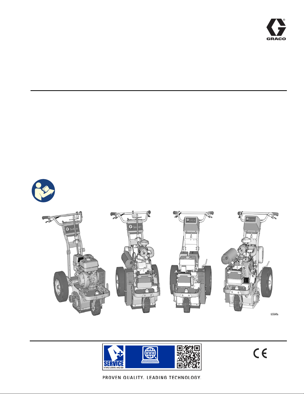
Graco GrindLazer 25M992, GrindLazer 25M993, GrindLazer 25M994, GrindLazer 25N658, GrindLazer 25N659 Operation Manual
Page 1
www.graco.com/techsupport
?? ??
Operation
25M992 / 25M993
25M994
(Drums, cutters, and LineDriver
™
sold separately)
25N659
25N658
™
GrindLazer
For removal of materials from flat horizontal concrete and asphalt surfaces. For
professional use only.
Model 25M992 - Forward Cut
GrindLazer HP DC89 G (270 cc / 9 hp)
Model 25M993 - Forward Cut
GrindLazer HP DC1013 G (390 cc / 13 hp)
Model 25M994 - Reverse Up-Cut (Must be used with LineDriver™)
GrindLazer HP DC1021 G (627 cc / 21 hp Electric Start)
Model 25N658 - Forward Cut
GrindLazer HP DC1013 G DCS (390 cc / 13 hp Electric Start)
Model 25N659 - Reverse Up-Cut (Must be used with LineDriver™)
GrindLazer HP DC1021 G DCS (627 cc / 21 hp Electric Start)
LineDriver ES Operation, Repair, Parts - 3A6623
LineDriver Operation - 312540
3A5918B
Related Manuals:
Repair - 3A5919
EN
Parts - 3A5929
IMPORTANT SAFETY INSTRUCTIONS
Read all warnings and instructions in this manual and in related manuals before using the equipment.
Be familiar with the controls and the proper usage of the equipment. Save all instructions.
Page 2

Contents
Contents
Warnings . . . . . . . . . . . . . . . . . . . . . . . . . . . . . . . . . 3
Battery Disposal . . . . . . . . . . . . . . . . . . . . . . . . . 4
Component Identification . . . . . . . . . . . . . . . . . . . . 5
Component Identification (DCS Models) . . . . . . . . 6
Setup . . . . . . . . . . . . . . . . . . . . . . . . . . . . . . . . . . . . . 7
Handle Bar Adjustment . . . . . . . . . . . . . . . . . . . . 7
Drum Installation/Replacement . . . . . . . . . . . . . . 7
Depth Control Wheels . . . . . . . . . . . . . . . . . . . . . 8
How to Level the Drum . . . . . . . . . . . . . . . . . . . . 8
Dust Control . . . . . . . . . . . . . . . . . . . . . . . . . . . . 9
DCS Control (DCS Models only) . . . . . . . . . . . . 10
Operation . . . . . . . . . . . . . . . . . . . . . . . . . . . . . . . . 14
Start-Up . . . . . . . . . . . . . . . . . . . . . . . . . . . . . . . 14
Starting the Engine . . . . . . . . . . . . . . . . . . . . . . 14
Cutting Material . . . . . . . . . . . . . . . . . . . . . . . . . 16
Cutting Drum Assemblies . . . . . . . . . . . . . . . . . 17
Stop Cutting Material . . . . . . . . . . . . . . . . . . . . . 18
Clean Up . . . . . . . . . . . . . . . . . . . . . . . . . . . . . . 18
DCS Instructions . . . . . . . . . . . . . . . . . . . . . . . . 19
Maintenance . . . . . . . . . . . . . . . . . . . . . . . . . . . . . . 21
Caster Wheel Maintenance . . . . . . . . . . . . . . . . 21
DCS Control Translations . . . . . . . . . . . . . . . . . . . 22
Technical Data . . . . . . . . . . . . . . . . . . . . . . . . . . . . 24
Graco Standard Warranty . . . . . . . . . . . . . . . . . . . 26
2 3A5918B
Page 3
Warnings
WARNING
Warnings
The following warnings are for the setup, use, grounding, maintenance, and repair of this equipment. The exclamation
point symbol alerts you to a general warning and the hazard symbols refer to procedure-specific risks. When these
symbols appear in the body of this manual or on warning labels, refer back to these Warnings. Product-specific hazard
symbols and warnings not covered in this section may appear throughout the body of this manual where applicable.
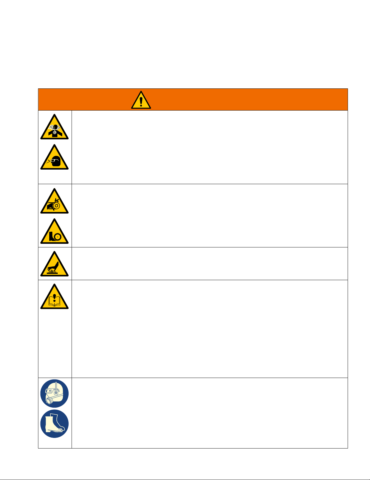
DUST AND DEBRIS HAZARD
Grinding concrete and other surfaces with this equipment can create dust that contains hazardous
substances. Grinding can also create flying debris.
To reduce the risk of serious injury:
• Control the dust to meet all applicable workplace regulations.
• Wear protective eye wear and a properly fit-tested and government approved respirator suitable for
the dust conditions.
• Use equipment only in a well-ventilated area.
• Grinding equipment must be used only by trained personnel who understand the applicable workplace regulations.
ENTANGLEMENT AND ROTATING PARTS HAZARD
Rotating parts can cut or amputate fingers and other body parts.
• Keep clear of rotating parts.
• Do not operate equipment with protective guards or covers removed.
• Do not wear loose clothing, jewelry or long hair while operating equipment.
• Before checking, moving, or servicing equipment, disable power supply.
BURN HAZARD
Cutters and engine can become very hot during operation. To avoid severe burns, do not touch hot
equipment. Wait until equipment has cooled completely.
EQUIPMENT MISUSE HAZARD
Misuse can cause death or serious injury.
• Do not operate the unit when fatigued or under the influence of drugs or alcohol.
• Do not leave the work area while equipment is energized. Turn off all equipment when equipment
is not in use.
• Check equipment daily. Repair or replace worn or damaged parts immediately with genuine manufacturer’s replacement parts only.
• Do not alter or modify equipment.
• Use equipment only for its intended purpose. Call your distributor for information.
• Keep children and animals away from work area.
• Comply with all applicable safety regulations.
• Maintain a safe operating distance from other people in the work area.
• Avoid any pipes, columns, openings, or any other objects protruding from work surface.
PERSONAL PROTECTIVE EQUIPMENT
You must wear appropriate protective equipment when operating, servicing, or when in the operating
area of the equipment to help protect you from serious injury, including eye injury, inhalation of dust or
chemicals, burns, and hearing loss. This equipment includes but is not limited to:
• Protective eye wear.
• Protective shoes.
• Gloves.
• Hearing protection.
• Properly fit-tested and government approved respirator suitable for the dust conditions.
3A5918B 3
Page 4
Warnings
WARNING
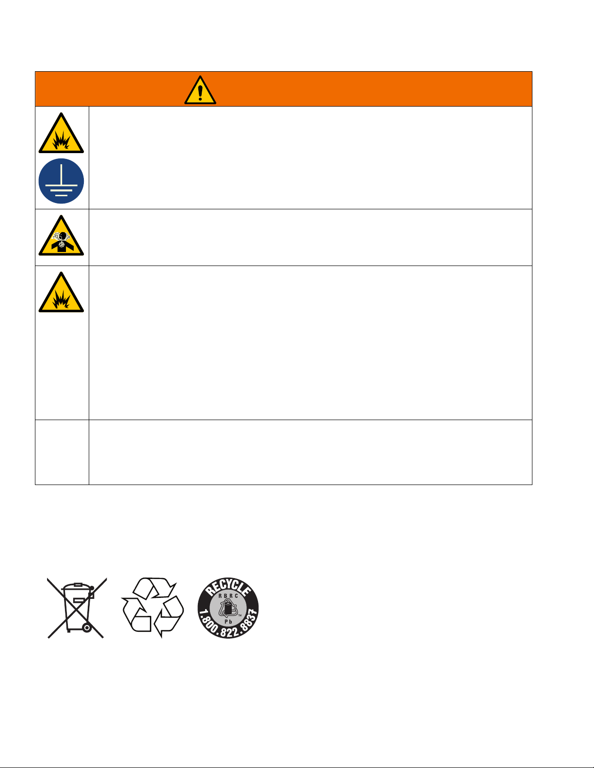
FIRE AND EXPLOSION HAZARD
Flammable fumes, such as solvent and paint fumes, in work area can ignite or explode. To help prevent fire and explosion:
• Use equipment only in well ventilated area.
• Do not fill fuel tank while engine is running or hot; shut off engine and let it cool. Fuel is flammable
and can ignite or explode if spilled on hot surface.
• Keep work area free of debris, including solvent, rags and gasoline.
• Keep a fire extinguisher in work area.
CARBON MONOXIDE HAZARD
Exhaust contains poisonous carbon monoxide, which is colorless and odorless. Breathing carbon
monoxide can cause death.
• Do not operate in an enclosed area.
BATTERY HAZARD
The battery may leak, explode, cause burns, or cause an explosion if mishandled. Contents of an open
battery can cause severe irritation and/or chemical burns. If on skin, wash with soap and water. If in
eyes, flush with water for at least 15 minutes and get immediate medical attention.
• Only use the battery type specified for use with the equipment. See Technical Data.
• Replace battery only in well-ventilated area and away from flammable or combustible materials,
including paints and solvents.
• Do not dispose of battery in fire or heat above 50°C (122°F). The battery is capable of exploding.
• Do not throw into fire.
• Do not expose battery to water or rain.
• Do not disassemble, crush, or penetrate the battery.
• Do not use or charge a battery that is cracked or damaged.
• Follow local ordinances and/or regulations for disposal.
CALIFORNIA PROPOSITION 65
The engine exhaust from this product contains a chemical known to the State of California to cause
cancer, birth defects or other reproductive harm.
This product contains a chemical known to the State of California to cause cancer, birth defects or
other reproductive harm. Wash hands after handling.
Battery Disposal
Do not place batteries in the trash. Recycle batteries according to local regulations. In the USA and Canada call
1-800-822-8837 to find recycling location or go to www.call2recycle.org.
4 3A5918B
Page 5
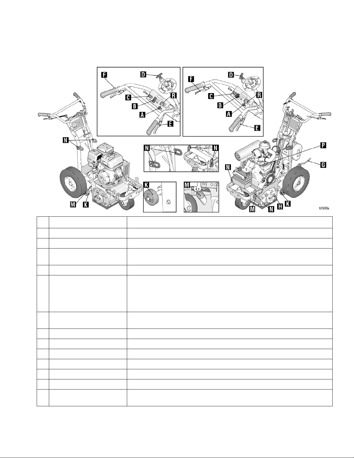
Component Identification
25M994
25M992 / 25M993
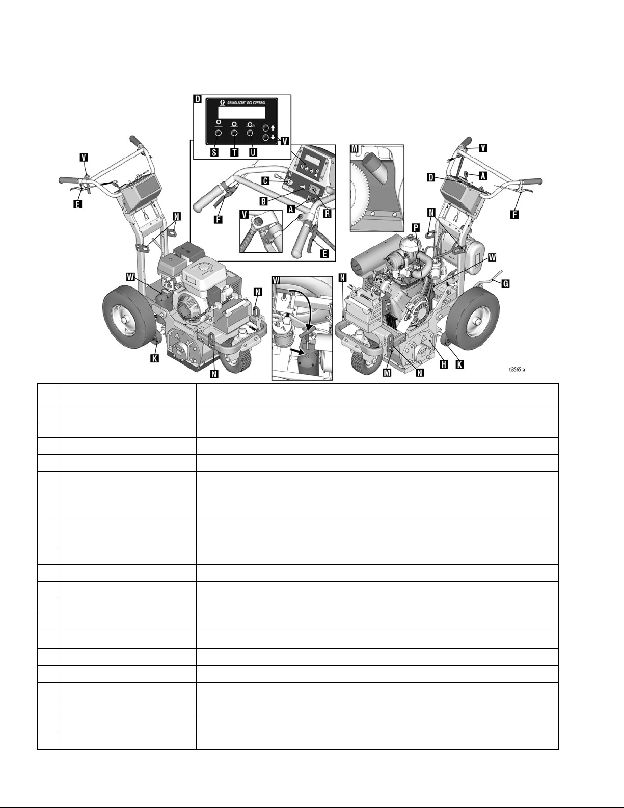
Component Identification
Component Description
A Engine Throttle Lever Adjusts engine speed.
B Power Switch Supplies power to Engine
C Engine Kill Button Clamps onto the operator and shuts engine off if cord is disconnected during oper-
ation.
D Drum Adjustment Dial Sets depth of drum cut.
E Drum Engage Lever Handle bars can be pushed down to raise the cutting drum off of surface and
locked into UP position. Once drum is locked in UP position, GrindLazer can be
moved around without drum touching surface. To lower the drum to the surface,
push down on handlebars, engage the Drum Engage Lever and then slowly pull
the handlebars up.
F Front Wheel Lock Lever Front wheel is usually locked to guide GrindLazer in a straight line. When lever is
engaged, front wheel becomes unlocked and is allowed to turn freely.
G Rear Wheel Parking Brake Prevents rear wheel from moving.
H Drum Access Panel Removable plate that allows access to replace cutting drum.
K Depth Control Wheels Levels cutting drum.
M Vacuum Port Port to attach vacuum to reduce dust and debris during operation.
N Lift Points Reinforced points used for lifting GrindLazer during transportaton or repair.
P Ignition Switch Electric Start Engine (DC1021 G Model Only)
R Tachometer/Hour Meter Displays the RPMs of the engine while running and displays total hours of engine
run time.
3A5918B 5
Page 6
Component Identification (DCS Models)
25N659
25N658
Component Identification (DCS Models)
Component Description
A Engine Throttle Lever Adjusts engine speed.
B Power Switch Supplies power to DCS Control and Engine.
C Engine Kill Button Clamps onto the operator and shuts engine off if cord is disconnected during operation.
D DCS Control Controls and displays depth of drum cut.
E Drum Engage Lever Handle bars can be pushed down to raise the cutting drum off of surface and locked into UP
position. Once drum is locked in UP position, GrindLazer can be moved around without drum
touching surface. To lower the drum to the surface, push down on handlebars, engage the
F Front Wheel Lock Lever Front wheel is usually locked to guide GrindLazer in a straight line. When lever is engaged,
G Rear Wheel Parking Brake Prevents rear wheel from moving.
H Drum Access Panel Removable plate that allows access to replace cutting drum.
K Depth Control Wheels Levels cutting drum.
M Vacuum Port Port to attach vacuum to reduce dust and debris during operation.
N Lift Points Reinforced points used for lifting GrindLazer during transportaton or repair.
P Ignition Switch Electric Start Engine.
R Tachometer/Hour Meter Displays the RPMs of the engine while running and displays total hours of engine run time.
S Home Button Raises drum off the surface to highest position.
T Zero Button Brings the drum to the surface (reprogrammable).
U Cut Depth Button Lowers drum to the desired cut depth target (reprogrammable).
V Up/Down Buttons Raises or Lowers the drum.
W Manual Height Adjustment Remove screw plug to adjust drum height using 6mm hex key.
Drum Engage Lever and then slowly pull the handlebars up.
front wheel becomes unlocked and is allowed to turn freely.
6 3A5918B
Page 7
Setup
S
S
Carbide Miller
Diamond Blade
PCD
ti15138a
ti15137a
Forward Cut
(25M992, 25M993 & 25N658)
Reverse Up-Cut
(25M994 & 25N659)
ti14766a
ti14764a
ti14756a
ti14755a
Models 25M992, 25M993 and 25N658 are designed to
be operated by a single operator positioned at the back
of the unit, or in conjunction with LineDriver. Models
25M994 and 25N659 can ONLY be operated with a
LineDriver.
Setup
To avoid unexpected startup, disconnect spark plug
wire before you service your unit.
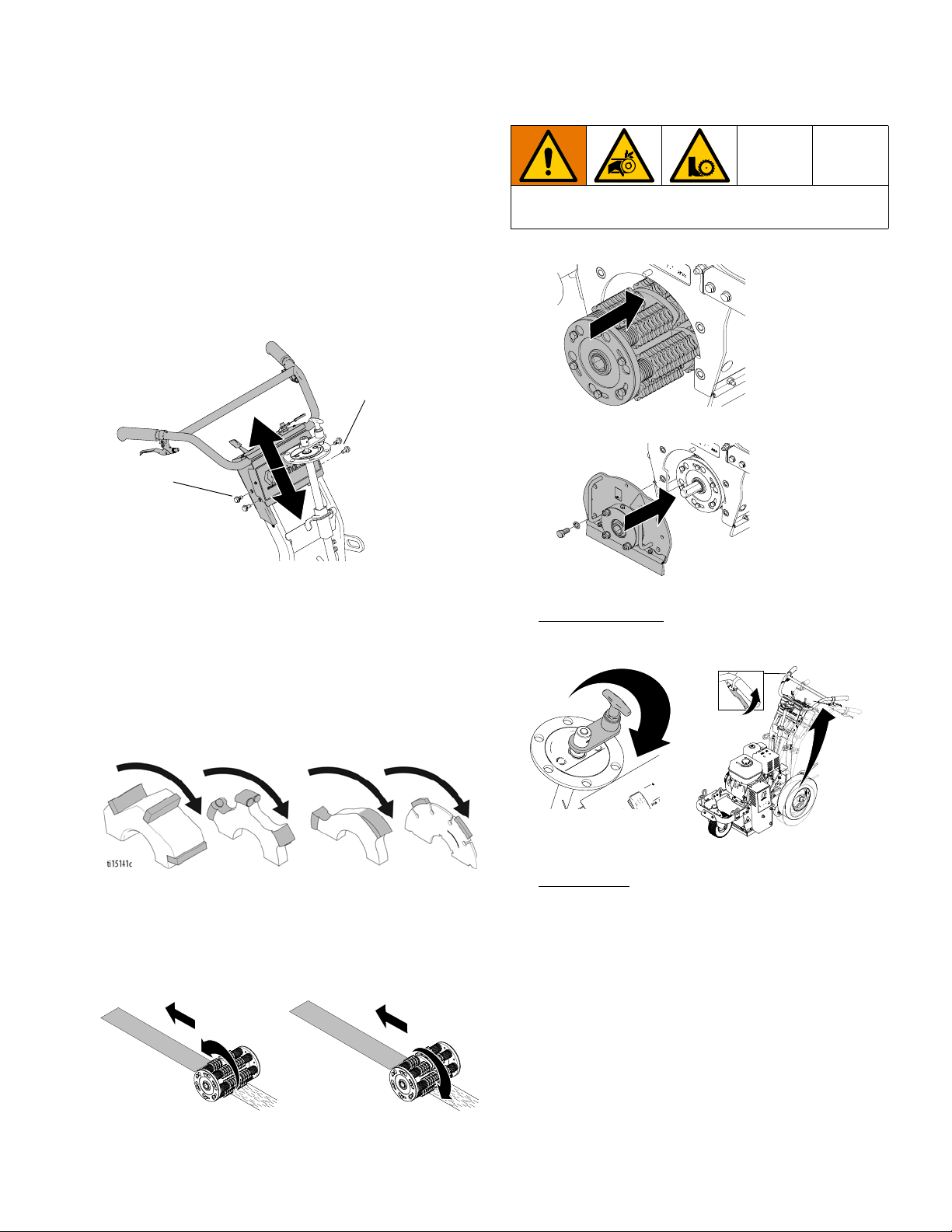
Handle Bar Adjustment
To adjust handle bar: remove four screws (S), slide
handle bar to desired height, and replace screws and
tighten.
Drum Installation/Replacement
Installation
NOTE: Carbide flail cutter drums do not require specific
orientation or direction. Carbide millers and diamond
blades are directional. They should be stacked so that
the arrows on the millers, PCDs, and blades face the
same direction as the rotation of the drum.
1. Slide replacement Drum onto hex shaft.
2. Replace Drum Access Panel (H).
3. Non-DCS Models
: Lower Drum Adjustment Dial (D)
and pull Drum Engage Lever (E) so drum rests on
ground and the door pin lines up with the hole.
Models 25M992, 25M993 and 25N658 are designed for
“forward cut” grinding (the drum rotates in the same
direction that it travels). Models 25M994 and 25N659
are designed for “reverse (up-cut)” grinding (the drum
rotates in the opposite direction that it travels).
3A5918B 7
DCS Models
: Pull the Drum Engage Lever (E) to
lower the drum. Turn the Power Switch ON (B). Use
the Up/Down Buttons (V) to raise/lower the drum
housing until the drum rests on the ground and the
door pin lines up with the hole.
Page 8
Setup
ti15257a
ti14767a
ti14765a
S
S
K
K
ti15095a
5 in.
S
S
K
K
ti15094a
10 in.
4. Once the proper drum height is achieved, slide the
Drum Access Panel onto the hex shaft and door pin.
5. Tighten four bolts on Drum Access Panel (H).
Depth Control Wheels
Using Depth Control Wheels as a 5 in. or 10
in. Wide Cutting Guide
To make a 5 in. cut, install two spacers (S) on outside
of Depth Control Wheels (K).
To make a 10 in. cut, install two spacers (S) on inside
of Depth Control Wheels (K).
6. Non-DCS Models
to maximum height.
DCS Models
DCS Control (D).
:Turn Drum Adjustment Dial (D)
: Press the Home Button (S) on the
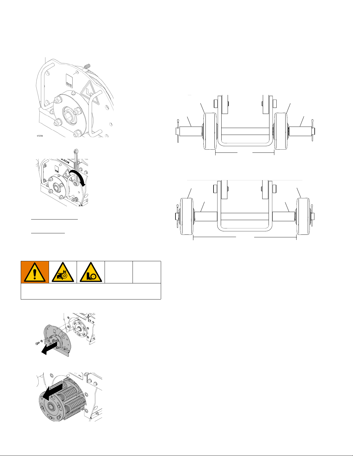
Removal
To avoid unexpected start up, disconnect spark plug
wire before you service your unit.
1. Remove four bolts and Drum Access Panel (H).
2. Slide drum off of hex shaft.
How to Level the Drum
To properly level the drum, GrindLazer must be resting
on a flat level surface.
Depth Control Wheels Adjustment
1. Make sure drum is properly installed (see Drum
Replacement, page 7).
2. Push down on handle bars, pull engagement lever,
and lower drum into DOWN position.
8 3A5918B
Page 9

Setup
T
ti15229a
ti28529a
3. Loosen (but do not remove) three bolts (T) on Depth
Control Wheel plate.
4. Adjust plate until guide wheels lay flat on surface.
5. Tighten three bolts (T) on plate.
Rear Axle Adjustment
If cut depth is uneven and the depth control wheels have
already been properly adjusted (see Depth Control
Wheels Adjustment, page 8), proceed with the
following rear axle adjustment steps.
Dust Control
Vacuum Attachment
1. If using a vacuum, attach vacuum hose to the
Vacuum Port.
2. Attach vacuum hose to the Inlet Port on the Cyclone
Separator (optional) and/or vacuum.
To avoid unexpected start up, disconnect spark plug
wire before you service your unit.
1. Measure the cut depth discrepancy.
2. Add equivalent washer thickness (to cut depth
discrepancy) between the frame and rear axle on
the side where it is cutting deep.
a. Loosen nuts on both sides of frame.
b. Add washer between axle and frame.
c. Torque both bolts to 12-15 ft-lbs.
3A5918B 9
Water Hookup
If using water for dust control, hook up water hose to the
fitting on top of drum housing. Turn water on.
Page 10

Setup
DCS Control (DCS Models only)
Buttons on the DCS Control have two functions, quick
press and long press. Quick press refers to pressing the
button and releasing the button quickly, while long press
is pressing the button and holding the button for two or
more seconds.
NOTE: “+” (plus) refers to above pavement surface. “-”
(minus) refers to below pavement surface.
Run Screen
Home Button
Zero Button
Quick Press: Takes the drum to the surface.
Long Press: Reprograms the zero point to the current
drum position.
Quick Press: Takes the drum to its highest position.
Long Press: Brings up Menu Screen.
10 3A5918B
Page 11

Setup
Cut Depth Button
Quick Press:
Long Press:
- If at or above zero point: Opens new screen to
select desired cut depth using up/down buttons.
- If below zero point: Reprograms the Cut Depth
Target to the current drum position.
Takes the drum to the Cut Depth Target.
•To exit without saving, quick press the Cut
Depth Button.
•To exit with saving, long press the Cut Depth
Button.
Up Arrow Button*
Quick Press: Raises the drum by 0.01” (0.25mm, 10
mil).
Long Press: Raises the drum to Home position.
Down Arrow Button*
Quick Press: Lowers the drum by 0.01” (25mm, 10
mil).
Long Press: Lowers the drum to Cut Depth Target.
*Handlebar Rocker Switch has the same functions as
Up and Down Arrow Buttons.
3A5918B 11
Page 12

Setup
Menu Screens
To display the Menu Screens, hold down Home Button
from the Run Screen. To save menu settings and return
to Run Screen, hold down Home Button from any Menu
Screen.
To cycle through selections in each Menu Screen, use
Up and Down Arrow Buttons.
To advance to next Menu Screen, quick press the Home
Button.
Menu Screen #1 - Language
Select your desired language (English, Spanish,
French, German, or International Symbols).
Menu Screen #3 - Model Select
Your GrindLazer model name can be found on the handlebar dashboard label. Select the model on the DCS
Control which matches the model you have. This
ensures accurate depth readings. Hold down Up or
Down Arrow Buttons to cycle through models.
Menu Screen #4 - Software revision
Displays the revision of the software on the DCS Control.
Menu Screen #2 - Units
Select your desired depth units (inches, millimeters, or
mils).
12 3A5918B
Page 13

Setup
Menu Screen #5 - Error Codes
Displays the most recent error code and the total number of times that error has occured. Cycle through previous error codes using Up/Down Buttons.
Error Codes
E04: High Voltage
E05: High Motor Current
E08: Low Voltage
E09: Hall Sensor Error
E12: High Current (short circuit)
E31: Home Button Error
E32: Zero Button Error
E33: Cut Depth Button Error
E34: Up Button Error
E35: Down Button Error
To clear an error code that appears while on the Run
Screen:
1. Turn DCS Power Switch OFF.
2. Address/Fix the issue.
3. Turn DCS Power Switch ON.
NOTE: See Repair Manual for more information on
Error Codes and Troubleshooting.
3A5918B 13
Page 14

Operation
ti15089a
ti14758a
Operation
Do not start machine while drum is in contact with the
ground. Doing so can cause the operator to lose
control of the machine, resulting in property damage
and/or personal injury.
Start-Up
Before starting engine, perform the following:
• Read and understand the engine manual.
• Make sure all guards are in place and secure.
• Make sure all mechanical fasteners are secure.
• Inspect for damage to engine and other exterior
surfaces.
• Use correct cutters for each job. Make sure drum is
balanced and the correct number, size and type of
cutter wheels are being used. Make sure drum shaft
is locked and secured.
• Inspect work area to locate any pipes, columns,
deck inserts, or other objects protruding from work
surface. Avoid these objects during operation.
2. 25M994 & 25N659 Models Only
to GrindLazer.
3. Push down on handle bars until drum is locked into
UP position.
4. DCS Models
(engine will not start if power switch is off). See DCS
Control (DCS Models only), page 10, for help
setting up your DCS Control.
: Turn DCS Control Power Switch ON
: Attach LineDriver
Starting the Engine
1. Engage Rear Wheel Brake (G) to prevent
GrindLazer from moving.
14 3A5918B
Page 15

Operation
ti15088a
ti5248a
25M992, 25M993 & 25N658 Models
ti5249a
25M994 & 25N659 Models
25M992, 25M993 & 25N658 Models
ti3315a
25M992 & 25M993 Models
TIA
25M992, 25M993 & 25N658 Models 25M994 & 25N659 Models
5. Non-DCS Models: Rotate Drum Adjustment Dial
counterclockwise until a hard stop is felt.
DCS Models
: Press the Home Button on DCS Con-
trol.
7. Start Engine:
a. Move fuel valve to open.
b. Move choke to closed.
c. Set Engine Power Switch (B) to ON.
6. 25M994 Model Only
is in UP position.
d. Pull starter cord, or turn key (electric start
models only) to start engine.
: Make sure Power Switch (B)
e. After engine starts, move choke to open.
3A5918B 15
Page 16

Operation
ti14755a
Cutting Material
Maintain a safe operating distance from other people
in the work area. Avoid any pipes, columns, openings,
or any other objects protruding from your work
surface.
1. Start Engine, see page 15.
2. Turn vacuum on, if using a vacuum.
3. Connect Engine Kill Button Cord to operator.
5. Push down on handle bars, pull engagement lever,
and lower drum into DOWN position slowly.
NOTE: Dropping the drum to the down position quickly
can cause damage to the drum and/or the DCS actuators.
6. Non-DCS Models
until drum comes into contact with surface and
desired depth is reached.
: Rotate Drum Adjustment Dial
4. Slide Engine Throttle to desired setting.
16 3A5918B
Page 17

Operation
DCS Models: On the DCS Control, press the Cut
Depth Button to lower the drum to the programmed
cut depth. See DCS Instructions, page 19, for more
details.
NOTE: Several test cuts may be needed to dial in
desired cutting depth.
NOTE: On harder surfaces, it may be best to make
several passes in increments of 1/32 in. (1mm) to get to
the desired depth.
Cutting Drum Assemblies
Diamond Blade Assembly
Watch Depth Control Wheels (K) during operation; if
wheels are rotating, proper depth is being achieved.
NOTICE
Diamond blades are designed to be cooled by airflow around the blades. Lift blade out of cut every
10 to 15 seconds, then run at full speed for several
seconds to prevent excessive heat build-up which
could damage the blades.
Cutter and Drum Assemblies
• The engine should not labor. Run engine at full
speed and adjust forward speed to fit the work being
performed. Harder concrete surfaces will have to be
cut at a slower pace than asphalt or other softer
surfaces.
Non-DCS Models
Adjustment Dial (D) is 0.010 in. (0.25 mm) depth change
of cutting drum.
: Each increment on Drum
BURN HAZARD
Avoid touching or handling drum after use until it has
completely cooled.
Different drum configurations can be used for different
applications.
Carbide Flail Cutter/Assembly
Gradually adjust depth down to remove marking line
(minimal amount of paved surface should be removed).
Carbide Miller Cutter/Assembly
Best results for deep cuts are achieved by making
several thin passes. A single pass should be no deeper
than 1/32 in. (1mm) or damage to rods and cutters could
occur.
3A5918B 17
Page 18

Operation
ti14758a
ti6482a
25M992 & 25M993
25M994
25N658 & 25N659
Stop Cutting Material
1. Push down on handle bars until drum is locked into
UP position.
2. Slide Engine Throttle Lever (A) to low setting.
Clean Up
BURN HAZARD
Avoid touching engine and drum after use until they
have completely cooled.
Clean the entire exterior of the machine after it has
cooled at the end of each work day. Check for worn or
damaged parts and perform any required Maintenance,
page 21.
3. Turn Power Switch (B) OFF.
18 3A5918B
Page 19

Operation
DCS Instructions
Each time the DCS Control is turned on, the DCS actuator will travel to the Home position.
Once the DCS Control finds Home, ensure the current
model is selected as well as your desired language and
units. See Menu Screens, page 12, for instructions on
changing these settings.
Set Zero Point:
Lower the Depth Control Wheels to the surface by using
the Drum Engage Lever to unlatch the drum housing
from the “up” position. With the engine on, lower the
drum by pressing the Down Arrow Button until you hear
the cutters make contact with the pavement surface.
Hold down the Zero Button for 2 seconds. Your Zero
Point has now been saved.
Set Cut Depth Target:
Quick press the Zero Button to take the drum to the
pavement surface. Set the Cut Depth Target by:
1. Quick pressing the Down Arrow Button as many
times as needed to achieve your target. Then long
press the Cut Depth Button to save your target.
NOTE: This method will lower the cutting drum into
the pavement surface as you set your cut depth.
OR
2. From the Zero Point, long press the Cut Depth Button until a new screen pops up. Use the Down
Arrow Button to enter your Cut Depth Target. Then
long press the Cut Depth Button to save your target
and return to the Run Screen.
NOTE: This method will keep the cutting drum stationary as you set your Cut Depth Target.
NOTE: The Cut Depth Target is based off of the Zero
Point. Re-program the Zero Point if the drum is changed
or worn.
3A5918B 19
Page 20

Operation
The DCS Control is now ready to grind/scarify. Long
press down on the Handlebar Rocker Switch to lower the
drum to your Cut Depth Target. Short press up or down
on the switch to adjust your Cut Depth on the fly. When
finished with your cut, long press up on the switch to
raise the drum to the Home position.
NOTE: The Zero Point and Cut Depth are referenced
from the Home position. Recalibrate your DCS Control
periodically by pressing the Home button or long pressing up on the Handlebar Rocker Switch.
NOTE: Pressing any button while the drum is moving to
Zero or Cut Depth will stop the command and halt the
drum from moving any further up or down until another
button is pressed.
Manual Height Adjustment
If the DCS Control is not usable (dead battery, etc.), the
drum height can be adjusted using the Manual Height
Adjustment feature.
1. Remove fuse from fuse holder near positive battery
terminal. This will protect the battery from damage.
3. Insert 6mm hex key into the port the screw plug was
removed from.
- One revolution of the hex key results in 1/8”
(3mm, 125 mil) of adjustment at the cutter drum.
- Rotate clockwise to lower the drum; rotate coun-
terclockwise to raise the drum. Max rotation
speed of 1 revolution per second. Do not use
power tools in the Manual Height Adjustment
port.
4. Once the desired depth is achieved, replace the
screw plug in order to keep water and dust out.
2. Use a 6mm hex key to remove the screw plug on the
top of the linear actuator.
20 3A5918B
Page 21

Maintenance
Avoid touching engine and drum after use until they
have completely cooled. To avoid unexpected start
up, disconnect spark plug wire before you service
your unit.
The following steps should be performed to maintain
proper operation and sustain the life of the GrindLazer.
BEFORE OPERATION:
• Visually inspect the entire unit for damage or loose
connections.
• Check engine oil (see engine manual).
• Check drum bushings and cutters.
• Check drum for uneven wear.
• Check for proper tire pressure.
DAILY:
• Insert and clean air filter element.
• Clean dust and debris from exterior of unit (do NOT
use pressure washer or other high pressure cleaning
equipment).
• Inspect dust skirts for damage. Repair or replace
damaged skirts in order to ensure optimal dust and
debris containment.
• If using water for dust control, clean out or replace
water hose if clogged or damaged.
Maintenance
AS REQUIRED:
• Check drive belt and tension and tighten or replace
as needed. For additional information about engine
maintenance, see Honda (270 and 390 models) or
Briggs and Stratton (480 models) engine manual.
Caster Wheel Maintenance
EVERY MONTH:
• Grease wheel bearing.
• Check pin for wear. If pin is worn out there will be
play in caster wheel. Reverse or replace pin as
needed.
• Check caster wheel alignment as necessary. To
align: loosen set screw, align wheel, and tighten
screw.
Front Swivel Tire Alignment
1. Loosen cap screw.
2. Rotate front wheel fork left or right, as necessary, to
straighten alignment.
3. Tighten cap screw. Push GrindLazer and let it roll
with hands off of GrindLazer.
NOTE: If GrindLazer rolls right or left, repeat steps 1 - 3
until GrindLazer rolls straight.
• Check engine oil level and fill as necessary.
• Check and fill gas tank.
• Remove air filter cover and clean element. Replace
element if necessary. Replacement elements can be
purchased from your local engine dealer.
AFTER THE FIRST 20 HOURS OF OPERATION:
• Drain engine oil and refill with clean oil. See engine
manual for correct viscosity.
EVERY 40-50 HOURS OF OPERATION:
• Change engine oil (see engine manual).
• Grease wheel bearings.
3A5918B 21
Page 22

DCS Control Translations
DCS Control Translations
English Español Français Deutsche International
FINDING HOME ENCONTRANDO INICIO
HOME INICIO
DEPTH ALTURA
TARGET OBJETIVO
ZERO CERO
TROUVER LE DÉBUT
DÉBUT
HAUTEUR
OBJECTIF
ZÉRO
START FINDEN
START
TIEFE
ZIEL
NULL
SEL MODEL MODELO
LANGUAGE IDIOMA
UNITS UNIDAD DE MEDIDA
INCHES PULGADAS
MILLIMETERS MILIMETROS
MILS MILS
SOFTWARE REV SOFTWARE REV
ERROR ERROR
MODELE
LA LANGUE
UNITÉ DE MESURE
POUCES
MILLIMETRES
MILS
REVUE SOFTWARE
ERREUR
MODELL
SPRACHE
MAßEINHEIT
ZOLL
MILLIMETER
MILS
SOFTWARE REV
FEHLER
INCH
MM
MIL
22 3A5918B
Page 23

DCS Control Translations
English Español Français Deutsche International
FREQUENCY FRECUENCIA
HIGH CURRENT ALTA CORRIENTE
LOW VOLTAGE BAJO VOLTAJE
HIGH VOLTAGE ALTO VOLTAJE
HALL SENSORS SENSORES DE HALL
HOME BUTTON BOTÓN DE INICIO
FRÉQUENCE
COURANT ÉLEVÉ
BASSE TENSION
HAUTE TENSION
CAPTEURS DE HALL
BOUTON DE DÉBUT
ANZHAL
HOHER STROM
NIEDERSPANNUNG
HOCHSPANNUNG
HALL-SENSOREN
START KNOPF
ZERO BUTTON BOTÓN CERO
CUT BUTTON BOTÓN DE CORTAR
UP BUTTON BOTÓN ARRIBA
DOWN BUTTON BOTÓN DE ABAJO
BOUTON ZÉRO
BOUTON DE COUPE
BOUTON HAUT
BOUTON BAS
NULLTASTE
SCHNITT TASTE
NACH OBEN TASTE
NACH UNTEN TASTE
3A5918B 23
Page 24

Technical Data
Technical Data
GrindLazer HP DC89 G (Model 25M992)
Dimensions
Unpackaged Packaged
Height in./cm: 46 (116.8) 50.5 (128.3)
Width in./cm: 28 (71.1) 37 (94.0)
Length in.cm: 62 (157.5) 73 (185.4)
Weight lb/kg: 300 (136) 400 (181)
Noise (dBa)
Sound Power per ISO 3744: 107.3
Sound Pressure measured at 3.1 feet (1m): 91.6
2
Vibration (m/sec
Without LineDriver: 7.9
With LineDriver: 8.3
Power Rating (HorsePower) per SAE J1349
8.0 @ 3600 rpm
Maximum storage time
Maximum lifetime
Power efficiency factor
5 years
10 years
200 ground meters per liter fuel
) per ISO 3744
GrindLazer HP DC1013 (Model 25M993)
Dimensions
Unpackaged Packaged
Height in./cm: 46 (116.8) 50.5 (128.3)
Width in./cm: 28 (71.1) 37 (94.0)
Length in.cm: 62 (157.5) 73 (185.4)
Weight lb/kg: 310 (141) 410 (186)
Noise (dBa)
Sound Power per ISO 3744: 109.3
Sound Pressure measured at 3.1 feet (1m): 93.6
2
Vibration (m/sec
Without LineDriver: 7.5
With LineDriver: 5.9
Power Rating (HorsePower) per SAE J1349
11.0 @ 3600 rpm
) per ISO 3744
24 3A5918B
Page 25

Technical Data
GrindLazer HP DC1021 G (Model 25M994)
Dimensions
Unpackaged Packaged
Height in./cm: 46 (116.8) 50.5 (128.3)
Width in./cm: 28 (71.1) 37 (94.0)
Length in.cm: 62 (157.5) 73 (185.4)
Weight lb/kg: 365 (165) 465 (211)
Noise (dBa)
Sound Power per ISO 3744: 108.6
Sound Pressure measured at 3.1 feet (1m): 92.1
2
Vibration (m/sec
With LineDriver: 4.9
Power Rating (HorsePower) per SAE J1349
21.0 @ 3600 rpm
) per ISO 3744
GrindLazer HP DC1013 G DCS (Model 25N658)
Dimensions
Unpackaged Packaged
Height in./cm: 46 (116.8) 50.5 (128.3)
Width in./cm: 28 (71.1) 37 (94.0)
Length in.cm: 62 (157.5) 73 (185.4)
Weight lb/kg: 355 (161) 455 (206)
Noise (dBa)
Sound Power per ISO 3744: 109.3
Sound Pressure measured at 3.1 feet (1m): 93.6
2
Vibration (m/sec
Without LineDriver: 7.5
With LineDriver: 5.9
Power Rating (HorsePower) per SAE J1349
11.0 @ 3600 rpm
) per ISO 3744
GrindLazer HP DC1021 G DCS (Model 25N659)
Dimensions
Unpackaged Packaged
Height in./cm: 46 (116.8) 50.5 (128.3)
Width in./cm: 28 (71.1) 37 (94.0)
Length in.cm: 62 (157.5) 73 (185.4)
Weight lb/kg: 385 (175) 485 (220)
Noise (dBa)
Sound Power per ISO 3744: 108.6
Sound Pressure measured at 3.1 feet (1m): 92.1
2
Vibration (m/sec
With LineDriver: 4.9
Power Rating (HorsePower) per SAE J1349
21.0 @ 3600 rpm
3A5918B 25
) per ISO 3744
Page 26

Graco Standard Warranty
Graco warrants all equipment referenced in this document which is manufactured by Graco and bearing its name to be free from defects in
material and workmanship on the date of sale to the original purchaser for use. With the exception of any special, extended, or limited warranty
published by Graco, Graco will, for a period of twelve months from the date of sale, repair or replace any part of the equipment determined by
Graco to be defective. This warranty applies only when the equipment is installed, operated and maintained in accordance with Graco’s written
recommendations.
This warranty does not cover, and Graco shall not be liable for general wear and tear, or any malfunction, damage or wear caused by faulty
installation, misapplication, abrasion, corrosion, inadequate or improper maintenance, negligence, accident, tampering, or substitution of
non-Graco component parts. Nor shall Graco be liable for malfunction, damage or wear caused by the incompatibility of Graco equipment with
structures, accessories, equipment or materials not supplied by Graco, or the improper design, manufacture, installation, operation or
maintenance of structures, accessories, equipment or materials not supplied by Graco.
This warranty is conditioned upon the prepaid return of the equipment claimed to be defective to an authorized Graco distributor for verification of
the claimed defect. If the claimed defect is verified, Graco will repair or replace free of charge any defective parts. The equipment will be returned
to the original purchaser transportation prepaid. If inspection of the equipment does not disclose any defect in material or workmanship, repairs
will be made at a reasonable charge, which charges may include the costs of parts, labor, and transportation.
THIS WARRANTY IS EXCLUSIVE, AND IS IN LIEU OF ANY OTHER WARRANTIES, EXPRESS OR IMPLIED, INCLUDING BUT NOT
LIMITED TO WARRANTY OF MERCHANTABILITY OR WARRANTY OF FITNESS FOR A PARTICULAR PURPOSE.
Graco’s sole obligation and buyer’s sole remedy for any breach of warranty shall be as set forth above. The buyer agrees that no other remedy
(including, but not limited to, incidental or consequential damages for lost profits, lost sales, injury to person or property, or any other incidental or
consequential loss) shall be available. Any action for breach of warranty must be brought within two (2) years of the date of sale.
GRACO MAKES NO WARRANTY, AND DISCLAIMS ALL IMPLIED WARRANTIES OF MERCHANTABILITY AND FITNESS FOR A
PARTICULAR PURPOSE, IN CONNECTION WITH ACCESSORIES, EQUIPMENT, MATERIALS OR COMPONENTS SOLD BUT NOT
MANUFACTURED BY GRACO. These items sold, but not manufactured by Graco (such as electric motors, switches, hose, etc.), are subject to
the warranty, if any, of their manufacturer. Graco will provide purchaser with reasonable assistance in making any claim for breach of these
warranties.
In no event will Graco be liable for indirect, incidental, special or consequential damages resulting from Graco supplying equipment hereunder, or
the furnishing, performance, or use of any products or other goods sold hereto, whether due to a breach of contract, breach of warranty, the
negligence of Graco, or otherwise.
FOR GRACO CANADA CUSTOMERS
The Parties acknowledge that they have required that the present document, as well as all documents, notices and legal proceedings entered into,
given or instituted pursuant hereto or relating directly or indirectly hereto, be drawn up in English. Les parties reconnaissent avoir convenu que la
rédaction du présente document sera en Anglais, ainsi que tous documents, avis et procédures judiciaires exécutés, donnés ou intentés, à la suite
de ou en rapport, directement ou indirectement, avec les procédures concernées.
Graco Information
For the latest information about Graco products, visit www.graco.com.
For patent information, see www.graco.com/patents.
TO PLACE AN ORDER, contact your Graco distributor or call 1-800-690-2894 to identify the nearest distributor.
All written and visual data contained in this document reflects the latest product information available at the time of publication.
GRACO INC. AND SUBSIDIARIES • P.O. BOX 1441 • MINNEAPOLIS MN 55440-1441 • USA
Copyright 2018, Graco Inc. All Graco manufacturing locations are registered to ISO 9001.
Graco reserves the right to make changes at any time without notice.
Original instructions. This manual contains English. MM 3A5918
Graco Headquarters: Minneapolis
International Offices: Belgium, China, Japan, Korea
www.graco.com
Revision
B, March 2019
 Loading...