

Graco GrindLazer 25M843, GrindLazer 25M842, GrindLazer 25N667, GrindLazer 25M846, GrindLazer 25N668 Operation - Repair - Parts
www.graco.com/techsupport
?? ??
Operation, Repair, Parts
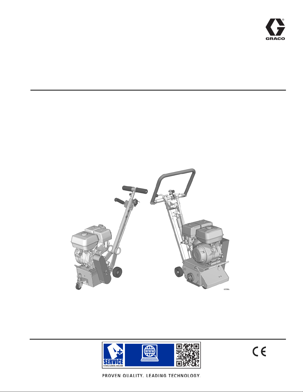
GrindLazer Standard Series
GrindLazer Pro Series
™
GrindLazer
For removal of materials from flat horizontal concrete and asphalt surfaces. For
professional use only.
Standard Series - Forward Cut
Model 25M842 - GrindLazer Standard DC87 G (200 cc / 6.5hp)
Model 25M843 - GrindLazer Standard DC89 G (270 cc / 9hp)
Pro Series - Forward Cut
Model 25M846 - GrindLazer Pro DC1013 G (390 cc / 13hp)
Model 25N667 - GrindLazer Pro DC89 G (270 cc / 9hp)
Model 25N668 - GrindLazer Pro DC1013 DCS (390 cc / 13hp Electric Start)
3A5578C
EN

Contents
Contents
Warnings . . . . . . . . . . . . . . . . . . . . . . . . . . . . . . . . . . . . . . . . . . . . . . . . . . . . . . . . . . . . . . . . . . . . . . . . . . . . . . . . . . . . . . . . . . . . . . . . . . . . . . . . . . . . 3
Component Identification . . . . . . . . . . . . . . . . . . . . . . . . . . . . . . . . . . . . . . . . . . . . . . . . . . . . . . . . . . . . . . . . . . . . . . . . . . . . . . . . . . . . . . . . . . . . . . . 5
GrindLazer Standard Series Models . . . . . . . . . . . . . . . . . . . . . . . . . . . . . . . . . . . . . . . . . . . . . . . . . . . . . . . . . . . . . . . . . . . . . . . . . . . . . . . . . . . 5
GrindLazer Pro Series Models . . . . . . . . . . . . . . . . . . . . . . . . . . . . . . . . . . . . . . . . . . . . . . . . . . . . . . . . . . . . . . . . . . . . . . . . . . . . . . . . . . . . . . . . 6
GrindLazer Pro Series DCS Models . . . . . . . . . . . . . . . . . . . . . . . . . . . . . . . . . . . . . . . . . . . . . . . . . . . . . . . . . . . . . . . . . . . . . . . . . . . . . . . . . . . . 7
Setup . . . . . . . . . . . . . . . . . . . . . . . . . . . . . . . . . . . . . . . . . . . . . . . . . . . . . . . . . . . . . . . . . . . . . . . . . . . . . . . . . . . . . . . . . . . . . . . . . . . . . . . . . . . . . . . 8
Handle Bar Adjustment (Pro Models Only) . . . . . . . . . . . . . . . . . . . . . . . . . . . . . . . . . . . . . . . . . . . . . . . . . . . . . . . . . . . . . . . . . . . . . . . . . . . . . . . 8
Engine Kill Button . . . . . . . . . . . . . . . . . . . . . . . . . . . . . . . . . . . . . . . . . . . . . . . . . . . . . . . . . . . . . . . . . . . . . . . . . . . . . . . . . . . . . . . . . . . . . . . . . . 8
Drum Installation/Replacement for GrindLazer Standard Series Models . . . . . . . . . . . . . . . . . . . . . . . . . . . . . . . . . . . . . . . . . . . . . . . . . . . . . . . . 8
Drum Installation/Replacement for GrindLazer Pro Series Models . . . . . . . . . . . . . . . . . . . . . . . . . . . . . . . . . . . . . . . . . . . . . . . . . . . . . . . . . . . . 9
Vacuum Attachment . . . . . . . . . . . . . . . . . . . . . . . . . . . . . . . . . . . . . . . . . . . . . . . . . . . . . . . . . . . . . . . . . . . . . . . . . . . . . . . . . . . . . . . . . . . . . . . 10
DCS Control (DCS Models only) . . . . . . . . . . . . . . . . . . . . . . . . . . . . . . . . . . . . . . . . . . . . . . . . . . . . . . . . . . . . . . . . . . . . . . . . . . . . . . . . . . . . . 11
Operation . . . . . . . . . . . . . . . . . . . . . . . . . . . . . . . . . . . . . . . . . . . . . . . . . . . . . . . . . . . . . . . . . . . . . . . . . . . . . . . . . . . . . . . . . . . . . . . . . . . . . . . . . . . 15
Machine Start Up . . . . . . . . . . . . . . . . . . . . . . . . . . . . . . . . . . . . . . . . . . . . . . . . . . . . . . . . . . . . . . . . . . . . . . . . . . . . . . . . . . . . . . . . . . . . . . . . . 15
Cutting Material . . . . . . . . . . . . . . . . . . . . . . . . . . . . . . . . . . . . . . . . . . . . . . . . . . . . . . . . . . . . . . . . . . . . . . . . . . . . . . . . . . . . . . . . . . . . . . . . . . 16
Cutting Drum Assemblies . . . . . . . . . . . . . . . . . . . . . . . . . . . . . . . . . . . . . . . . . . . . . . . . . . . . . . . . . . . . . . . . . . . . . . . . . . . . . . . . . . . . . . . . . . . 17
Stop Cutting Material . . . . . . . . . . . . . . . . . . . . . . . . . . . . . . . . . . . . . . . . . . . . . . . . . . . . . . . . . . . . . . . . . . . . . . . . . . . . . . . . . . . . . . . . . . . . . . 18
DCS Instructions . . . . . . . . . . . . . . . . . . . . . . . . . . . . . . . . . . . . . . . . . . . . . . . . . . . . . . . . . . . . . . . . . . . . . . . . . . . . . . . . . . . . . . . . . . . . . . . . . . 19
Maintenance . . . . . . . . . . . . . . . . . . . . . . . . . . . . . . . . . . . . . . . . . . . . . . . . . . . . . . . . . . . . . . . . . . . . . . . . . . . . . . . . . . . . . . . . . . . . . . . . . . . . . . . . 21
DCS Control Translations . . . . . . . . . . . . . . . . . . . . . . . . . . . . . . . . . . . . . . . . . . . . . . . . . . . . . . . . . . . . . . . . . . . . . . . . . . . . . . . . . . . . . . . . . . . . . 22
Repair . . . . . . . . . . . . . . . . . . . . . . . . . . . . . . . . . . . . . . . . . . . . . . . . . . . . . . . . . . . . . . . . . . . . . . . . . . . . . . . . . . . . . . . . . . . . . . . . . . . . . . . . . . . . . . 24
Drum Replacement for GrindLazer Standard Series Models . . . . . . . . . . . . . . . . . . . . . . . . . . . . . . . . . . . . . . . . . . . . . . . . . . . . . . . . . . . . . . . . 24
Drum Replacement for GrindLazer Pro Series Models . . . . . . . . . . . . . . . . . . . . . . . . . . . . . . . . . . . . . . . . . . . . . . . . . . . . . . . . . . . . . . . . . . . . 24
Belt Replacement (Standard Models) . . . . . . . . . . . . . . . . . . . . . . . . . . . . . . . . . . . . . . . . . . . . . . . . . . . . . . . . . . . . . . . . . . . . . . . . . . . . . . . . . . 25
Belt Replacement (Pro Models) . . . . . . . . . . . . . . . . . . . . . . . . . . . . . . . . . . . . . . . . . . . . . . . . . . . . . . . . . . . . . . . . . . . . . . . . . . . . . . . . . . . . . . 27
Belt Alignment . . . . . . . . . . . . . . . . . . . . . . . . . . . . . . . . . . . . . . . . . . . . . . . . . . . . . . . . . . . . . . . . . . . . . . . . . . . . . . . . . . . . . . . . . . . . . . . . . . . 29
Bearing Replacement (Standard Models) . . . . . . . . . . . . . . . . . . . . . . . . . . . . . . . . . . . . . . . . . . . . . . . . . . . . . . . . . . . . . . . . . . . . . . . . . . . . . . 29
Bearing Replacement (Pro Models) . . . . . . . . . . . . . . . . . . . . . . . . . . . . . . . . . . . . . . . . . . . . . . . . . . . . . . . . . . . . . . . . . . . . . . . . . . . . . . . . . . . 30
Diamond (High Speed) Kit Installation (Pro Models Only) . . . . . . . . . . . . . . . . . . . . . . . . . . . . . . . . . . . . . . . . . . . . . . . . . . . . . . . . . . . . . . . . . . 32
Troubleshooting . . . . . . . . . . . . . . . . . . . . . . . . . . . . . . . . . . . . . . . . . . . . . . . . . . . . . . . . . . . . . . . . . . . . . . . . . . . . . . . . . . . . . . . . . . . . . . . . . . . . . 33
DCS Models only . . . . . . . . . . . . . . . . . . . . . . . . . . . . . . . . . . . . . . . . . . . . . . . . . . . . . . . . . . . . . . . . . . . . . . . . . . . . . . . . . . . . . . . . . . . . . . . . . 34
DCS Error Codes . . . . . . . . . . . . . . . . . . . . . . . . . . . . . . . . . . . . . . . . . . . . . . . . . . . . . . . . . . . . . . . . . . . . . . . . . . . . . . . . . . . . . . . . . . . . . . . . . 35
DCS Actuator Rod Does Not Move . . . . . . . . . . . . . . . . . . . . . . . . . . . . . . . . . . . . . . . . . . . . . . . . . . . . . . . . . . . . . . . . . . . . . . . . . . . . . . . . . . . 37
Parts . . . . . . . . . . . . . . . . . . . . . . . . . . . . . . . . . . . . . . . . . . . . . . . . . . . . . . . . . . . . . . . . . . . . . . . . . . . . . . . . . . . . . . . . . . . . . . . . . . . . . . . . . . . . . . . 38
Drive Assembly (25M842) . . . . . . . . . . . . . . . . . . . . . . . . . . . . . . . . . . . . . . . . . . . . . . . . . . . . . . . . . . . . . . . . . . . . . . . . . . . . . . . . . . . . . . . . . . 38
Drive Assembly Parts List (25M842) . . . . . . . . . . . . . . . . . . . . . . . . . . . . . . . . . . . . . . . . . . . . . . . . . . . . . . . . . . . . . . . . . . . . . . . . . . . . . . . . . . 39
Drive Assembly (25M843) . . . . . . . . . . . . . . . . . . . . . . . . . . . . . . . . . . . . . . . . . . . . . . . . . . . . . . . . . . . . . . . . . . . . . . . . . . . . . . . . . . . . . . . . . . 40
Drive Assembly Parts List (25M843) . . . . . . . . . . . . . . . . . . . . . . . . . . . . . . . . . . . . . . . . . . . . . . . . . . . . . . . . . . . . . . . . . . . . . . . . . . . . . . . . . . 41
Guide Bar Assembly (25M842 and 25M843) . . . . . . . . . . . . . . . . . . . . . . . . . . . . . . . . . . . . . . . . . . . . . . . . . . . . . . . . . . . . . . . . . . . . . . . . . . . . 42
Guide Bar Assembly (25M842 and 25M843) Parts List . . . . . . . . . . . . . . . . . . . . . . . . . . . . . . . . . . . . . . . . . . . . . . . . . . . . . . . . . . . . . . . . . . . . 43
Primary Housing Assembly (25M842 and 25M843) . . . . . . . . . . . . . . . . . . . . . . . . . . . . . . . . . . . . . . . . . . . . . . . . . . . . . . . . . . . . . . . . . . . . . . . 44
Primary Housing Assembly (25M842 and 25M843) Parts List . . . . . . . . . . . . . . . . . . . . . . . . . . . . . . . . . . . . . . . . . . . . . . . . . . . . . . . . . . . . . . . 45
Drum Housing Assembly (25M842 and 25M843) . . . . . . . . . . . . . . . . . . . . . . . . . . . . . . . . . . . . . . . . . . . . . . . . . . . . . . . . . . . . . . . . . . . . . . . . . 46
Drum Housing Assembly (25M842 and 25M843) Parts List . . . . . . . . . . . . . . . . . . . . . . . . . . . . . . . . . . . . . . . . . . . . . . . . . . . . . . . . . . . . . . . . . 46
Bearing and Shaft Assembly (25M846, 25N667 & 25N668) . . . . . . . . . . . . . . . . . . . . . . . . . . . . . . . . . . . . . . . . . . . . . . . . . . . . . . . . . . . . . . . . 47
Bearing and Shaft Assembly (25M846, 25N667 & 25N668) Parts List . . . . . . . . . . . . . . . . . . . . . . . . . . . . . . . . . . . . . . . . . . . . . . . . . . . . . . . . 47
Rear Assembly (25M846 & 25N667) . . . . . . . . . . . . . . . . . . . . . . . . . . . . . . . . . . . . . . . . . . . . . . . . . . . . . . . . . . . . . . . . . . . . . . . . . . . . . . . . . . 48
Rear Assembly (25M846 & 25N667) Parts List . . . . . . . . . . . . . . . . . . . . . . . . . . . . . . . . . . . . . . . . . . . . . . . . . . . . . . . . . . . . . . . . . . . . . . . . . . 49
Rear Assembly (25N668) . . . . . . . . . . . . . . . . . . . . . . . . . . . . . . . . . . . . . . . . . . . . . . . . . . . . . . . . . . . . . . . . . . . . . . . . . . . . . . . . . . . . . . . . . . . 50
Rear Assembly (25N668) Parts List . . . . . . . . . . . . . . . . . . . . . . . . . . . . . . . . . . . . . . . . . . . . . . . . . . . . . . . . . . . . . . . . . . . . . . . . . . . . . . . . . . . 51
Damper Assembly (25M846, 25N667) . . . . . . . . . . . . . . . . . . . . . . . . . . . . . . . . . . . . . . . . . . . . . . . . . . . . . . . . . . . . . . . . . . . . . . . . . . . . . . . . . 52
Damper Assembly (25M846 & 25N667) Parts List . . . . . . . . . . . . . . . . . . . . . . . . . . . . . . . . . . . . . . . . . . . . . . . . . . . . . . . . . . . . . . . . . . . . . . . . 52
Front Assembly (25M846, 25N667 & 25N668) . . . . . . . . . . . . . . . . . . . . . . . . . . . . . . . . . . . . . . . . . . . . . . . . . . . . . . . . . . . . . . . . . . . . . . . . . . . 54
Front Assembly (25M846, 25N667 & 25N668) Parts List . . . . . . . . . . . . . . . . . . . . . . . . . . . . . . . . . . . . . . . . . . . . . . . . . . . . . . . . . . . . . . . . . . . 55
Handle Bar Assembly (25M846) . . . . . . . . . . . . . . . . . . . . . . . . . . . . . . . . . . . . . . . . . . . . . . . . . . . . . . . . . . . . . . . . . . . . . . . . . . . . . . . . . . . . . . 56
Handle Bar Assembly (25M846) Parts List . . . . . . . . . . . . . . . . . . . . . . . . . . . . . . . . . . . . . . . . . . . . . . . . . . . . . . . . . . . . . . . . . . . . . . . . . . . . . . 56
Handle Bar Assembly (25N668) . . . . . . . . . . . . . . . . . . . . . . . . . . . . . . . . . . . . . . . . . . . . . . . . . . . . . . . . . . . . . . . . . . . . . . . . . . . . . . . . . . . . . . 57
Handle Bar Assembly (25N668) Parts List . . . . . . . . . . . . . . . . . . . . . . . . . . . . . . . . . . . . . . . . . . . . . . . . . . . . . . . . . . . . . . . . . . . . . . . . . . . . . . 57
Drive Assembly (25M846 & 25N667) . . . . . . . . . . . . . . . . . . . . . . . . . . . . . . . . . . . . . . . . . . . . . . . . . . . . . . . . . . . . . . . . . . . . . . . . . . . . . . . . . . 58
Drive Assembly (25M846 & 25N667) Parts List . . . . . . . . . . . . . . . . . . . . . . . . . . . . . . . . . . . . . . . . . . . . . . . . . . . . . . . . . . . . . . . . . . . . . . . . . . 59
Drive Assembly (25N668) . . . . . . . . . . . . . . . . . . . . . . . . . . . . . . . . . . . . . . . . . . . . . . . . . . . . . . . . . . . . . . . . . . . . . . . . . . . . . . . . . . . . . . . . . . . 60
Drive Assembly (25N668) Parts List . . . . . . . . . . . . . . . . . . . . . . . . . . . . . . . . . . . . . . . . . . . . . . . . . . . . . . . . . . . . . . . . . . . . . . . . . . . . . . . . . . . 61
DCS Control Box 18A790 . . . . . . . . . . . . . . . . . . . . . . . . . . . . . . . . . . . . . . . . . . . . . . . . . . . . . . . . . . . . . . . . . . . . . . . . . . . . . . . . . . . . . . . . . . . . . . 62
25N668 only . . . . . . . . . . . . . . . . . . . . . . . . . . . . . . . . . . . . . . . . . . . . . . . . . . . . . . . . . . . . . . . . . . . . . . . . . . . . . . . . . . . . . . . . . . . . . . . . . . . . . 62
Parts List . . . . . . . . . . . . . . . . . . . . . . . . . . . . . . . . . . . . . . . . . . . . . . . . . . . . . . . . . . . . . . . . . . . . . . . . . . . . . . . . . . . . . . . . . . . . . . . . . . . . . . . . 62
Wiring Diagram . . . . . . . . . . . . . . . . . . . . . . . . . . . . . . . . . . . . . . . . . . . . . . . . . . . . . . . . . . . . . . . . . . . . . . . . . . . . . . . . . . . . . . . . . . . . . . . . . . . . . . 63
DCS System . . . . . . . . . . . . . . . . . . . . . . . . . . . . . . . . . . . . . . . . . . . . . . . . . . . . . . . . . . . . . . . . . . . . . . . . . . . . . . . . . . . . . . . . . . . . . . . . . . . . . 63
DCS Control Box . . . . . . . . . . . . . . . . . . . . . . . . . . . . . . . . . . . . . . . . . . . . . . . . . . . . . . . . . . . . . . . . . . . . . . . . . . . . . . . . . . . . . . . . . . . . . . . . . 64
Technical Data . . . . . . . . . . . . . . . . . . . . . . . . . . . . . . . . . . . . . . . . . . . . . . . . . . . . . . . . . . . . . . . . . . . . . . . . . . . . . . . . . . . . . . . . . . . . . . . . . . . . . . . 65
CALIFORNIA PROPOSITION 65 . . . . . . . . . . . . . . . . . . . . . . . . . . . . . . . . . . . . . . . . . . . . . . . . . . . . . . . . . . . . . . . . . . . . . . . . . . . . . . . . . . . . . 66
Graco Standard Warranty . . . . . . . . . . . . . . . . . . . . . . . . . . . . . . . . . . . . . . . . . . . . . . . . . . . . . . . . . . . . . . . . . . . . . . . . . . . . . . . . . . . . . . . . . . . . . . 67
2 3A5578C
Warnings
WARNING
Warnings
The following warnings are for the setup, use, grounding, maintenance, and repair of this equipment. The exclamation
point symbol alerts you to a general warning and the hazard symbols refer to procedure-specific risks. When these
symbols appear in the body of this manual or on warning labels, refer back to these Warnings. Product-specific hazard
symbols and warnings not covered in this section may appear throughout the body of this manual where applicable.
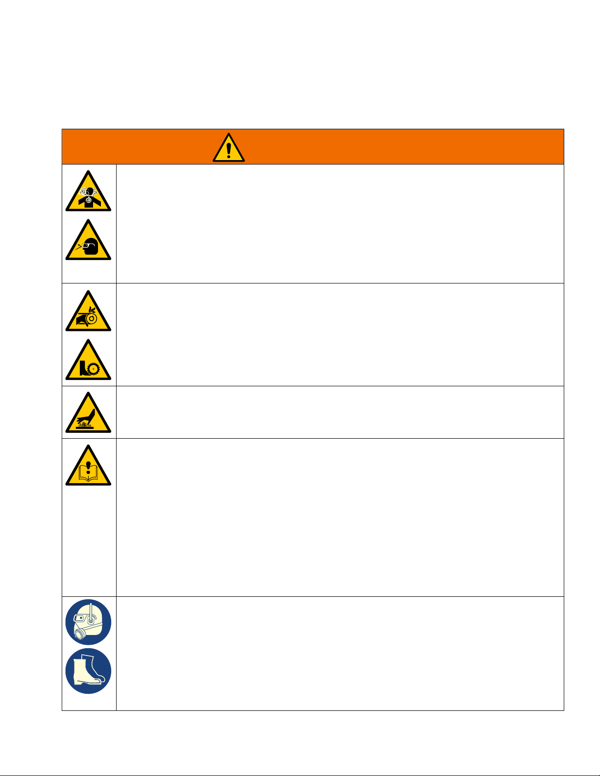
DUST AND DEBRIS HAZARD
Grinding concrete and other surfaces with this equipment can create dust that contains hazardous
substances. Grinding can also create flying debris.
To reduce the risk of serious injury:
• Control the dust to meet all applicable workplace regulations.
• Wear protective eye wear and a properly fit-tested and government approved respirator suitable for
the dust conditions.
• Use equipment only in a well-ventilated area.
• Grinding equipment must be used only by trained personnel who understand the applicable workplace regulations.
ENTANGLEMENT AND ROTATING PARTS HAZARD
Rotating parts can cut or amputate fingers and other body parts.
• Keep clear of rotating parts.
• Do not operate equipment with protective guards or covers removed.
• Do not wear loose clothing, jewelry or long hair while operating equipment.
• Before checking, moving, or servicing equipment, disable power supply.
BURN HAZARD
Cutters and engine can become very hot during operation. To avoid severe burns, do not touch hot
equipment. Wait until equipment has cooled completely.
EQUIPMENT MISUSE HAZARD
Misuse can cause death or serious injury.
• Do not operate the unit when fatigued or under the influence of drugs or alcohol.
• Do not leave the work area while equipment is energized. Turn off all equipment when equipment
is not in use.
• Check equipment daily. Repair or replace worn or damaged parts immediately with genuine manufacturer’s replacement parts only.
• Do not alter or modify equipment.
• Use equipment only for its intended purpose. Call your distributor for information.
• Keep children and animals away from work area.
• Comply with all applicable safety regulations.
• Maintain a safe operating distance from other people in the work area.
• Avoid any pipes, columns, openings, or any other objects protruding from work surface.
PERSONAL PROTECTIVE EQUIPMENT
You must wear appropriate protective equipment when operating, servicing, or when in the operating
area of the equipment to help protect you from serious injury, including eye injury, inhalation of dust or
chemicals, burns, and hearing loss. This equipment includes but is not limited to:
• Protective eye wear.
• Protective shoes.
• Gloves.
• Hearing protection.
• Properly fit-tested and government approved respirator suitable for the dust conditions.
3A5578C 3
Warnings
WARNING
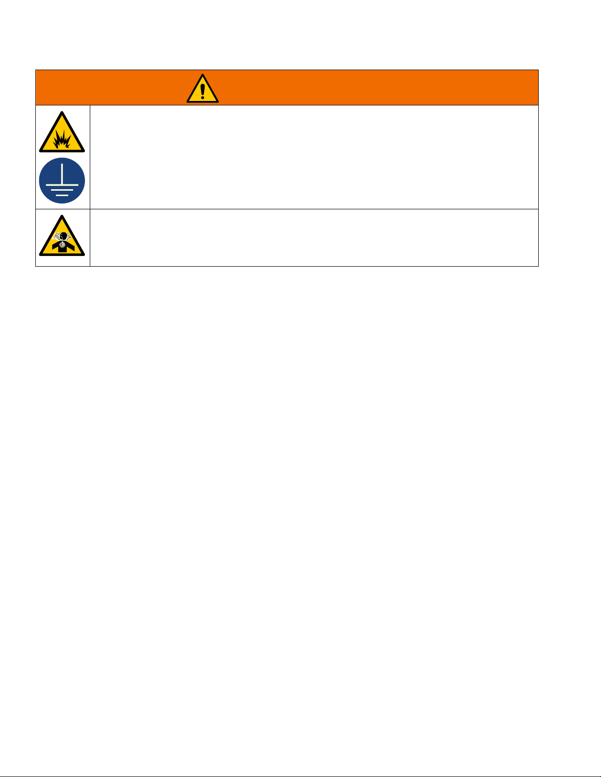
FIRE AND EXPLOSION HAZARD
Flammable fumes, such as solvent and paint fumes, in work area can ignite or explode. To help prevent fire and explosion:
• Use equipment only in well ventilated area.
• Do not fill fuel tank while engine is running or hot; shut off engine and let it cool. Fuel is flammable
and can ignite or explode if spilled on hot surface.
• Keep work area free of debris, including solvent, rags and gasoline.
• Keep a fire extinguisher in work area.
CARBON MONOXIDE HAZARD
Exhaust contains poisonous carbon monoxide, which is colorless and odorless. Breathing carbon
monoxide can cause death.
• Do not operate in an enclosed area.
4 3A5578C
Component Identification
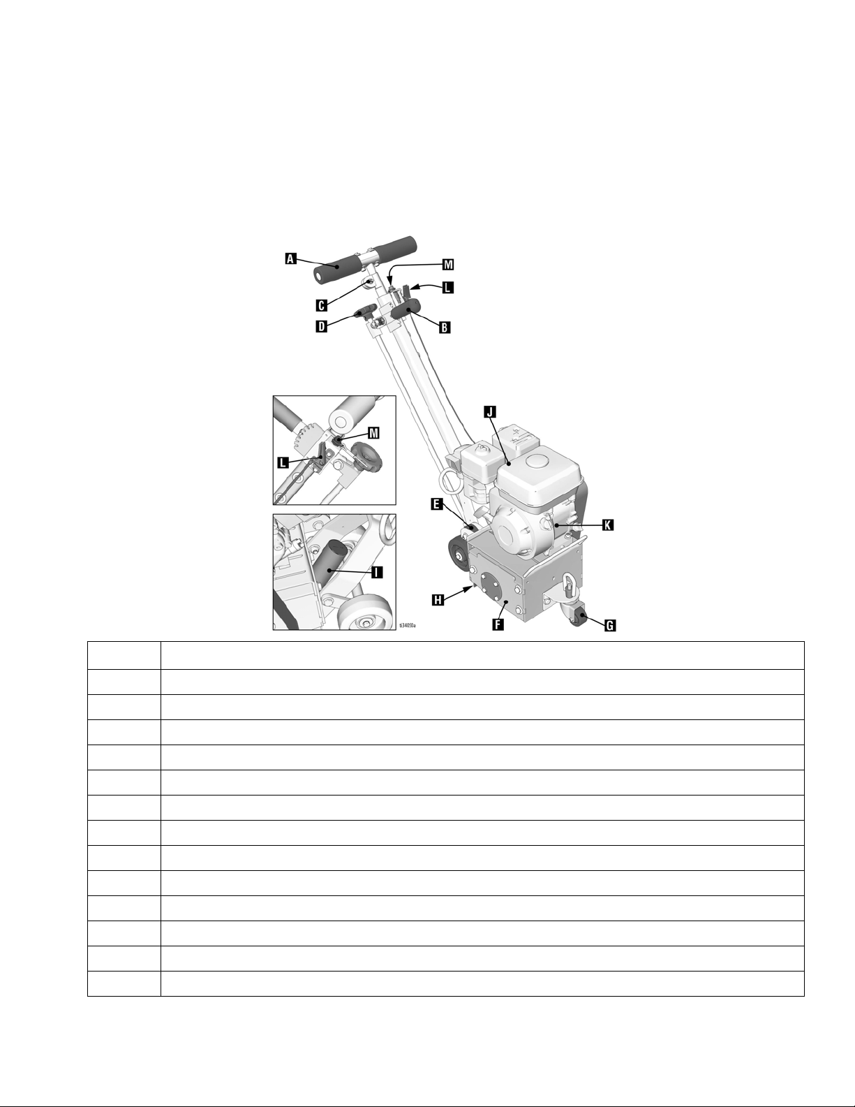
GrindLazer Standard Series Models
Component Identification
A Handlebar
B Depth Engage Lever (coarse adjustment)
C Locking Nut (for handle height adjustment)
D Drum Adjustment Dial (fine adjustments)
E Fixed Front Wheel (optional)
F Drum Access Panel
G Feathering Front Wheel
HDust Skirt
I Vacuum Port
JEngine
K Engine Power Switch
L Engine Throttle
M Engine Kill Button
Component
3A5578C 5
Component Identification
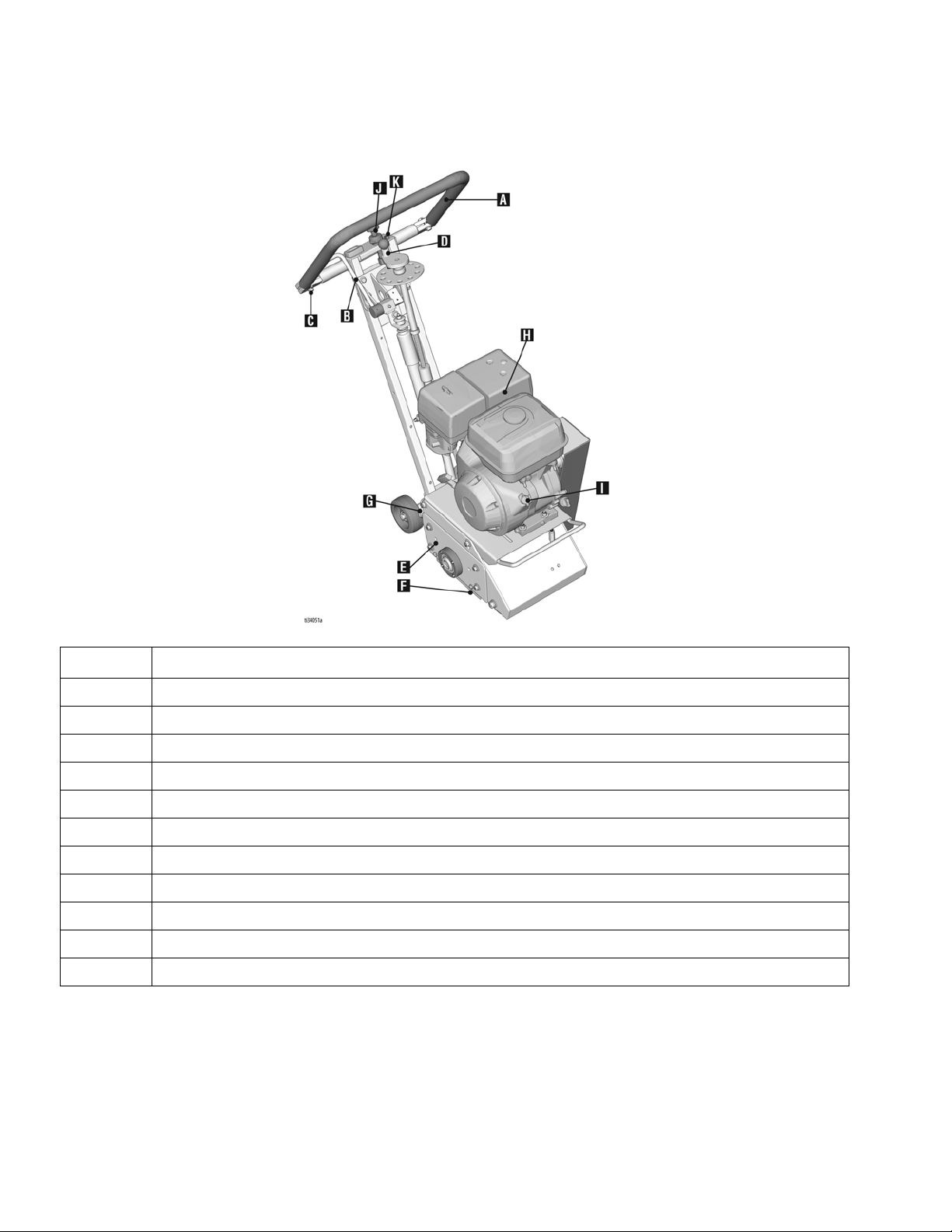
GrindLazer Pro Series Models
A Handlebar
B Drum Engage Lever
C Handlebar Adjustment Bolts
D Drum Adjustment Dial
E Drum Access Panel
FDust Skirt
G Vacuum Port
HEngine
I Engine Power Switch
J Engine Throttle
K Engine Kill Button
Component
6 3A5578C

GrindLazer Pro Series DCS Models
Component Identification
Component
A Handlebar
BPower Switch
C Handlebar Adjustment Bolts
D DCS Control
E Pressure Control Dial
FDust Skirt
GVacuum Port
HEngine
I Electric Start Engine Switch
J Engine Throttle
3A5578C 7
K Engine Kill Button
L Pressure Indicator
M Wheel Stop
N Hour Meter/Tachometer
S Home Button
T Zero Button
U Cut Depth Button
V Up/Down Buttons
W Manual Height Adjustment
Component
Setup
Setup
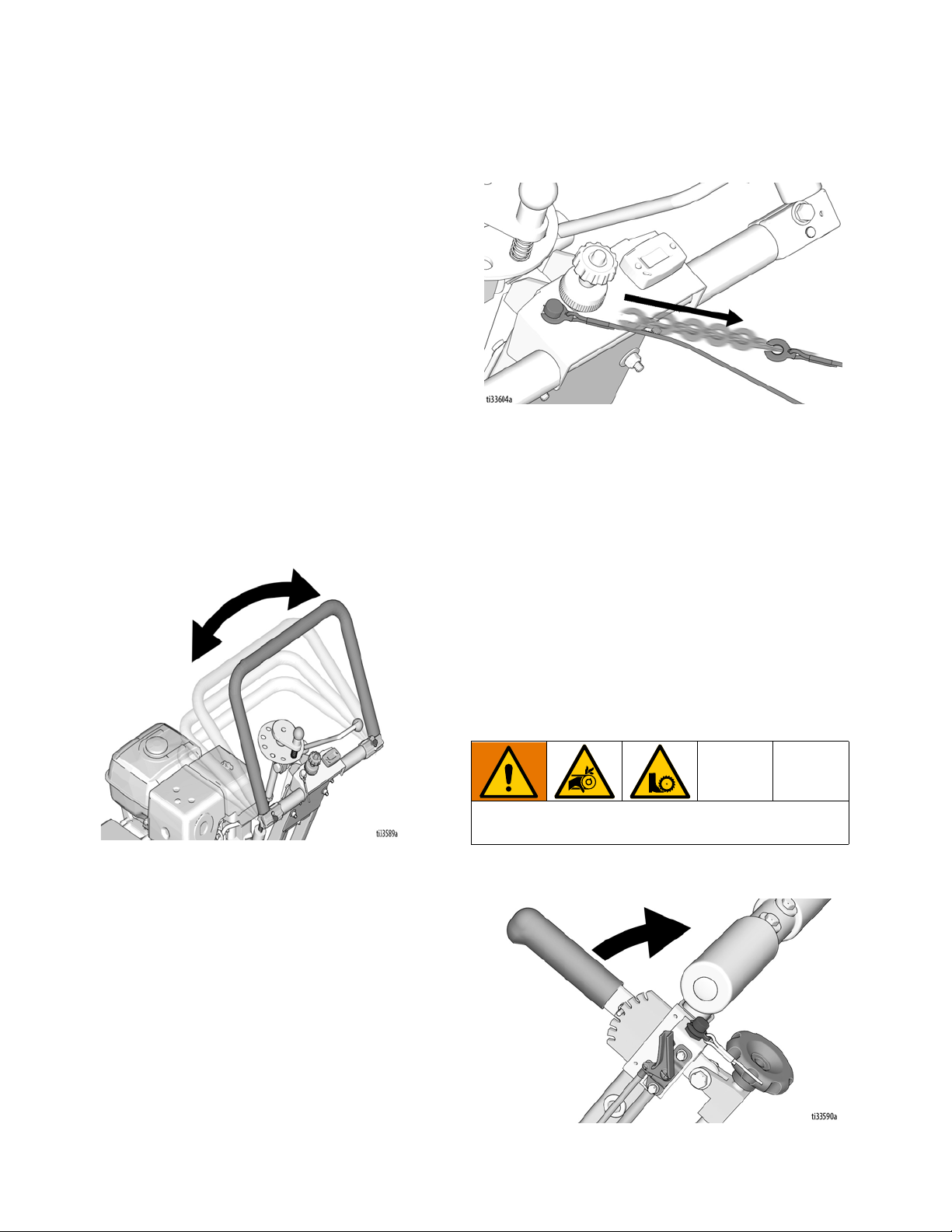
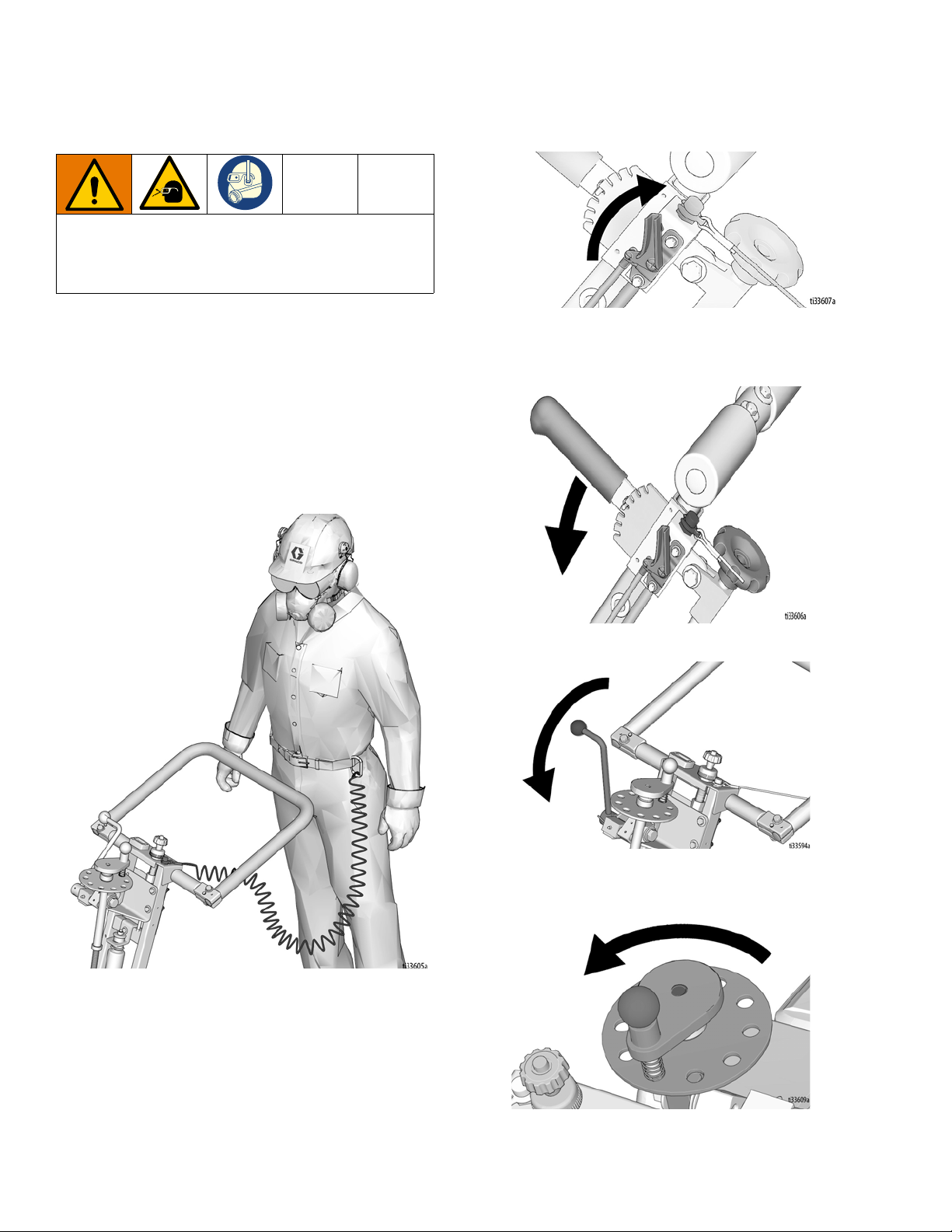
Handle Bar Adjustment (Pro Models Only)
The handlebars are equipped with a high-density
vibration suppression material to reduce operator fatigue
when operating equipment. To adjust the handlebars to
a new position for different height operators please follow
these steps:
1. Using a 9/16” (14mm) wrench or socket, loosen the
bolts on both sides of the handlebars until the
handlebar moves freely.
2. Stand behind the machine and lightly tap the
handlebar to the desired position.
3. Re-tighten the bolts to 260-300 in-lb (29-34 N•m) to
lock the handlebars into position.
NOTE: Never operate equipment with loose handlebars.
The bolts must be fastened tightly assuring the handle is
locked into position.
stopped by pressing down on the Engine Kill Button.
Drum Installation/Replacement for GrindLazer Standard Series Models
Normal use will require periodic drum inspection and
may necessitate drum replacement. Time of
replacement will vary according to usage and load
factors.
Engine Kill Button
In the event of a malfunction or an accident (such as the
machine operator falling or losing footing), the
GrindLazer is equipped with a corded Engine Kill Button.
Attach the end of the cord to the operator’s belt or wrist,
and snap the clip into place on the button by raising the
top of the Engine Kill Button and inserting the clip into the
gap. If the operator becomes distanced too far from the
machine, the cord will detach from the button and the
machine will stop running. The engine can also be
Tools needed:
1. 17mm socket or wrench
2. Rubber mallet
To avoid injury from unexpected start up, disconnect
spark plug wire before you service your unit.
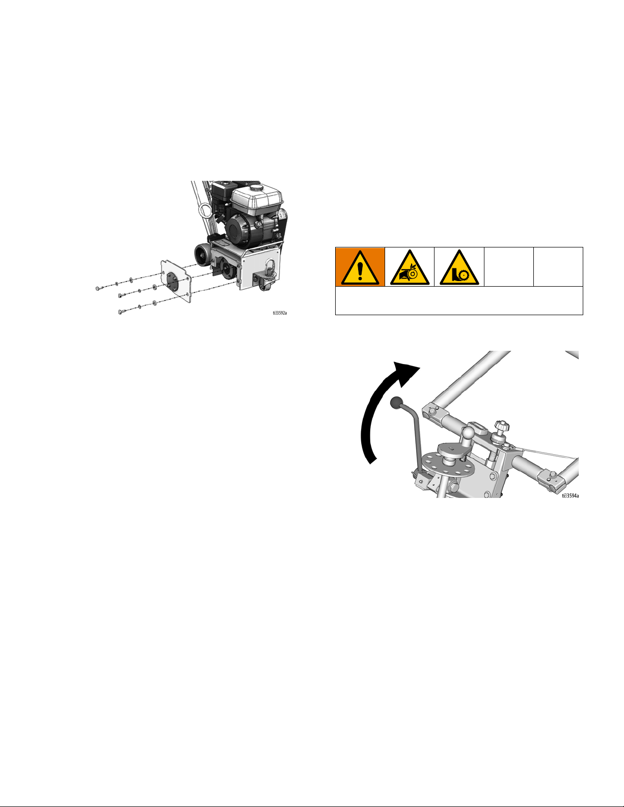
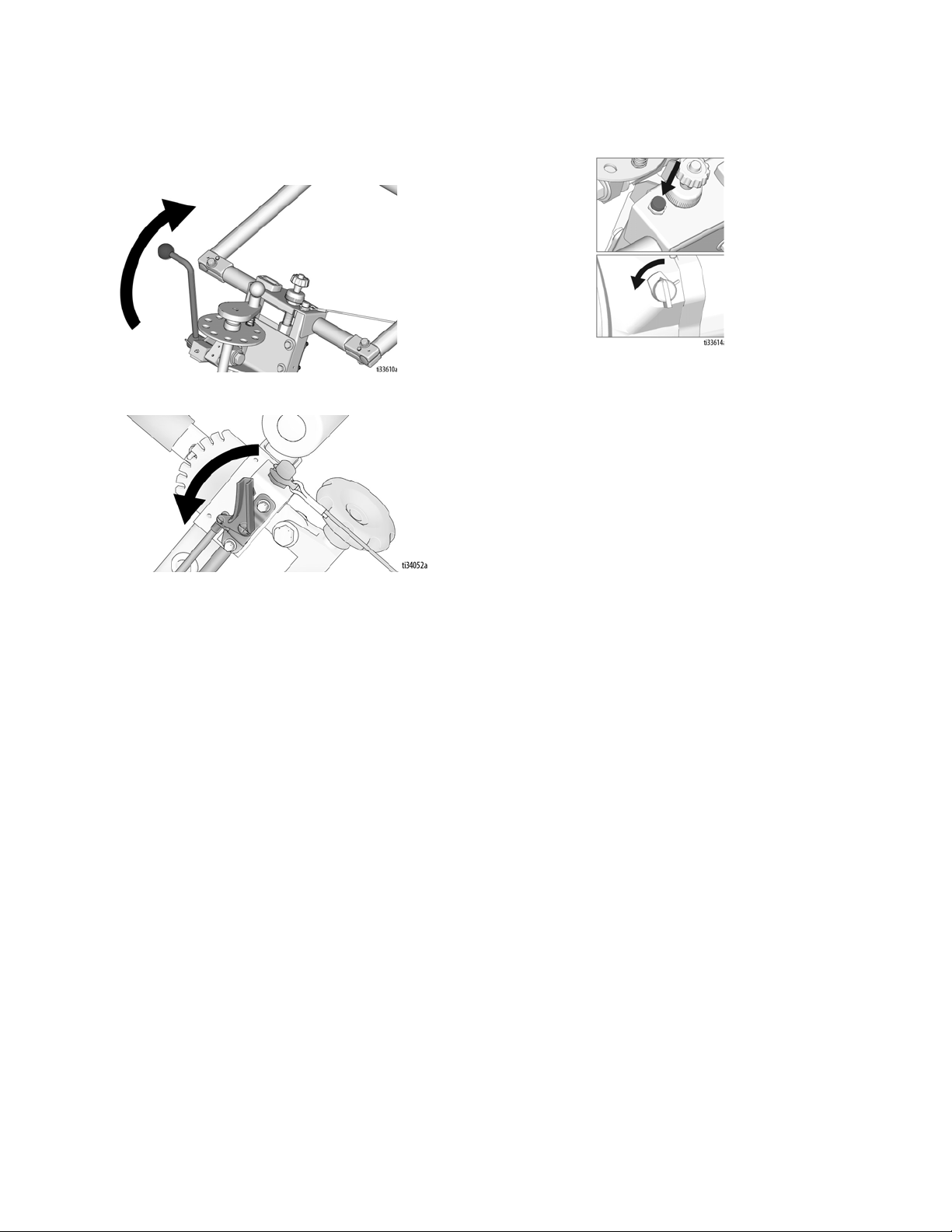
1. Raise the Drum Engage Lever to the up position so
the cutter drum is off the ground.
8 3A5578C
Setup
2. Remove the three hex head cap screws from the
Drum Access Panel using the 17mm socket or
wrench.
3. Remove Drum Access Panel (this may require the
rubber mallet to break it loose).
4. Slide out drum assembly (use caution as it is
heavy).
5. Once the cutter drum is removed, take to a
workbench for assembly.
a. Inspect condition of cutters, spacers, shafts,
bushings and drum.
Drum Installation/Replacement for GrindLazer Pro Series Models
Normal use will require periodic drum inspection and
may necessitate drum replacement. Time of
replacement will vary according to usage and load
factors. Tools needed:
1. 9/16” socket or wrench.
2. Rubber mallet.
To avoid injury from unexpected start up, disconnect
spark plug wire before you service your unit.
1. Raise the Drum Engage Lever to the up position so
the cutter drum is off the ground.
6. Before replacing the drum onto hex shaft:
a. Check that all bearings are in good working
order.
b. Remove dirt and material build-up from inside
drive carriage and drum.
c. Lube all metal contacts.
7. Align and slide drum back onto the hex shaft.
8. Replace Drum Access Panel (lift up and lock into
place) over hex shaft and secure hardware.
NOTE: An extra drum loaded with cutters for rapid job
site replacement is recommended.
2. Remove the four hex head cap screws from the
Drum Access Panel using the 9/16” socket or
wrench.
3. Remove the Drum Access Panel (this may require
the rubber mallet to break it loose).
3A5578C 9
Setup
4. Slide out drum assembly (use caution as it is
heavy).
5. Once the cutter drum is removed take to a
workbench for assembly.
a. Inspect condition of cutters, spacers, shafts,
bushings and drum.
6. Before replacing the drum onto hex shaft:
a. Check that all bearings are in good working
order.
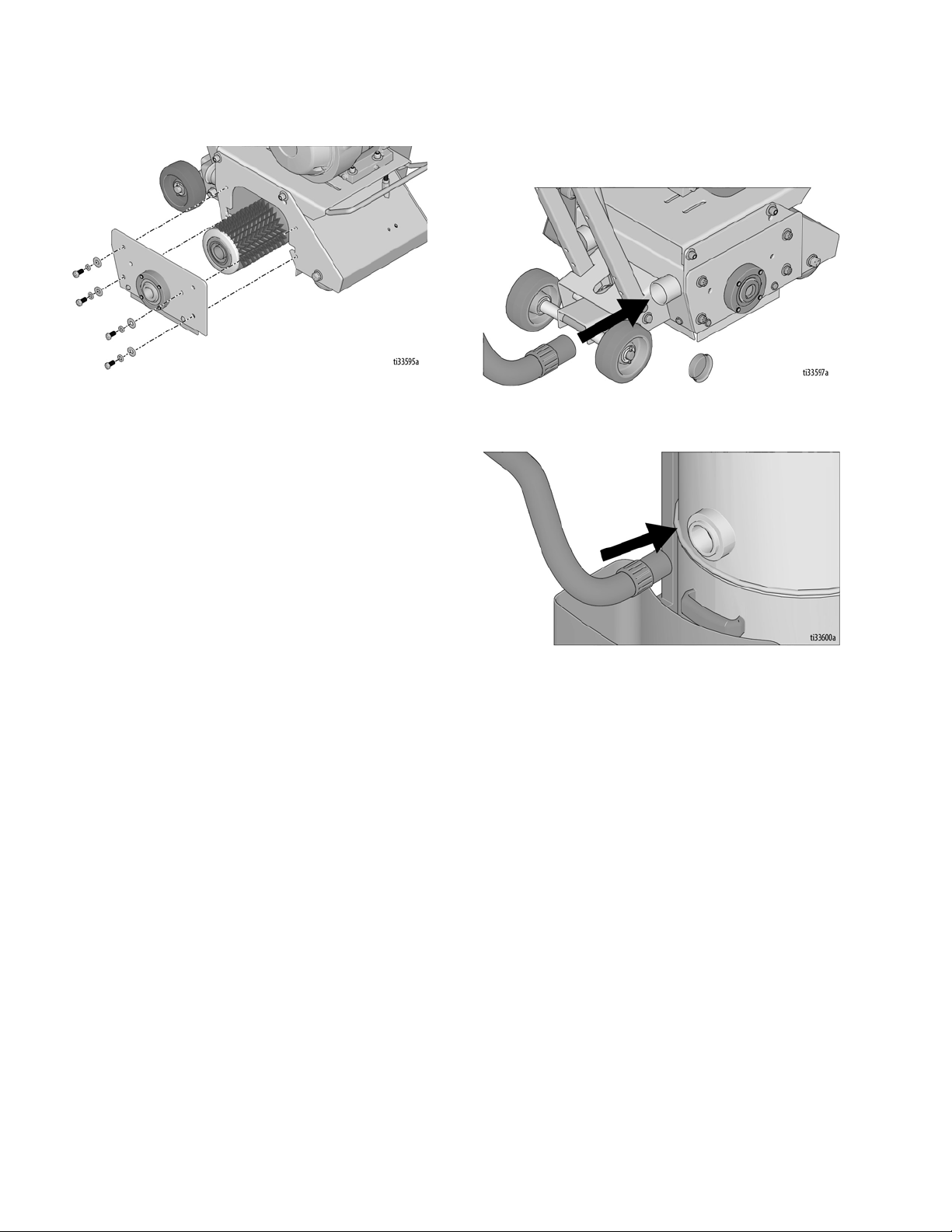
Vacuum Attachment
1. If using a vacuum, attach vacuum hose to the
Vacuum Port.
2. Attach vacuum hose to the Inlet Port on the Cyclone
Separator (optional) or vacuum. \
b. Remove dirt and material build-up from inside
drive carriage and drum.
c. Lube all metal contacts.
7. Align and slide drum back onto the hex shaft.
8. Replace Drum Access Panel (lift up and lock into
place) over hex shaft and secure hardware.
NOTE: An extra drum loaded with cutters for rapid job
site replacement is recommended.
10 3A5578C

DCS Control (DCS Models only)
Setup
Buttons on the DCS Control have two functions, quick
press and long press. Quick press refers to pressing the
button and releasing the button quickly, while long press
is pressing the button and holding the button for two or
more seconds.
NOTE: “+” (plus) refers to above pavement surface. “-”
(minus) refers to below pavement surface.
Run Screen
Home Button
Zero Button
Quick Press: Takes the drum to the surface.
Long Press: Reprograms the zero point to the current
drum position.
Quick Press: Takes the drum to its highest position.
Long Press: Brings up Menu Screen.
3A5578C 11

Setup
Cut Depth Button
Quick Press:
Long Press:
- If at or above zero point: Opens new screen to
select desired cut depth using up/down buttons.
- If below zero point: Reprograms the Cut Depth
Target to the current drum position.
Takes the drum to the Cut Depth Target.
•To exit without saving, quick press the Cut
Depth Button.
•To exit with saving, long press the Cut Depth
Button.
Up Arrow Button*
Quick Press: Raises the drum by 0.01” (0.25mm, 10
mil).
Long Press: Raises the drum to Home position.
Down Arrow Button*
Quick Press: Lowers the drum by 0.01” (25mm, 10
mil).
Long Press: Lowers the drum to Cut Depth Target.
*Handlebar Rocker Switch has the same functions as
Up and Down Arrow Buttons.
12 3A5578C
Setup
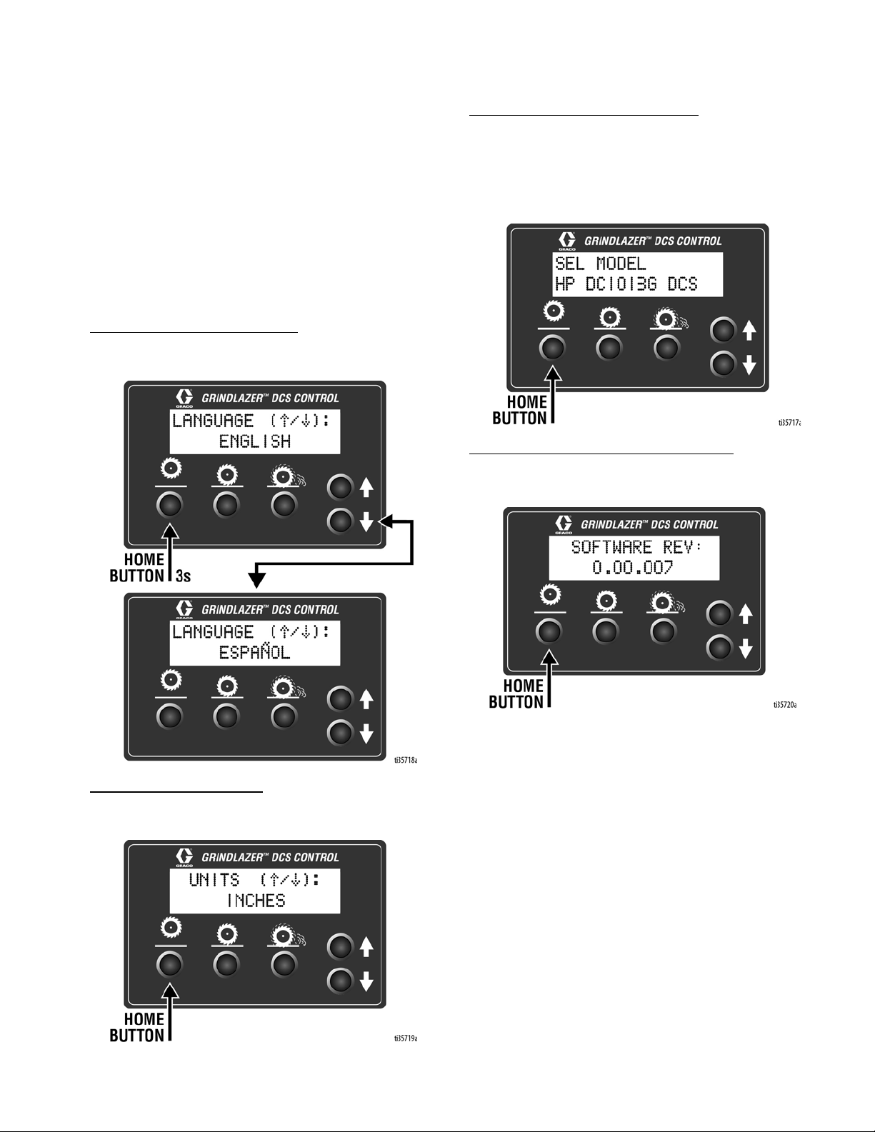
Menu Screens
To display the Menu Screens, hold down Home Button
from the Run Screen. To save menu settings and return
to Run Screen, hold down Home Button from any Menu
Screen.
To cycle through selections in each Menu Screen, use
Up and Down Arrow Buttons.
To advance to next Menu Screen, quick press the Home
Button.
Menu Screen #1 - Language
Select your desired language (English, Spanish,
French, German, or International Symbols).
Menu Screen #3 - Model Select
Your GrindLazer model name can be found on the handlebar dashboard label. Select the model on the DCS
Control which matches the model you have. This
ensures accurate depth readings. Hold down Up or
Down Arrow Buttons to cycle through models.
Menu Screen #4 - Software revision
Displays the revision of the software on the DCS Control.
Menu Screen #2 - Units
Select your desired depth units (inches, millimeters, or
mils).
3A5578C 13
Setup
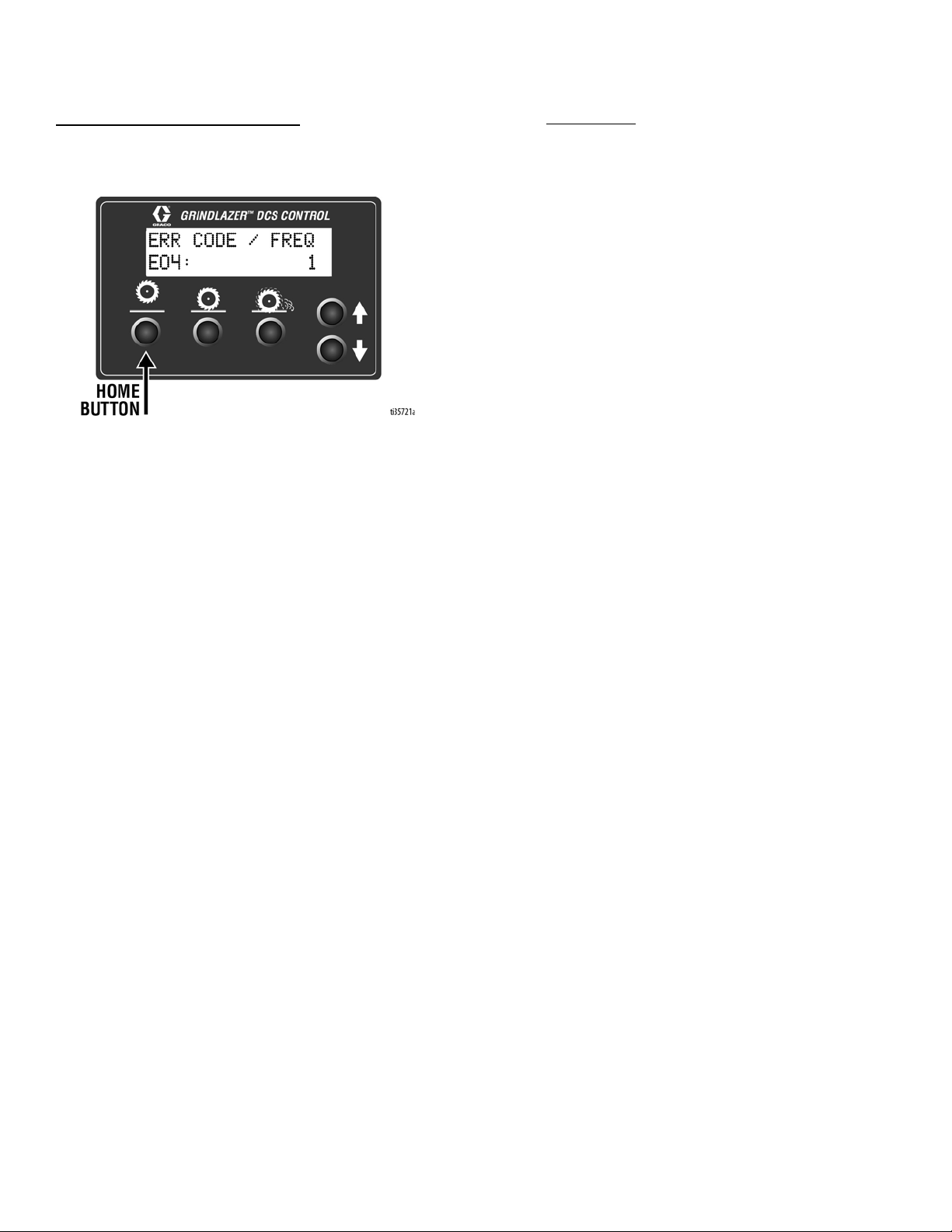
Menu Screen #5 - Error Codes
Displays the most recent error code and the total number of
times that error has occured. Cycle through previous error
codes using Up/Down Buttons.
Error Codes
E04: High Voltage
E05: High Motor Current
E08: Low Voltage
E09: Hall Sensor Error
E12: High Current (short circuit)
E31: Home Button Error
E32: Zero Button Error
E33: Cut Depth Button Error
E34: Up Button Error
E35: Down Button Error
To clear an error code that appears while on the Run
Screen:
1. Turn DCS Power Switch OFF.
2. Address/Fix the issue.
3. Turn DCS Power Switch ON.
NOTE: See Repair Manual for more information on Error
Codes and Troubleshooting.
14 3A5578C
Operation
Operation
Do not start machine while drum is in contact with the
ground. Doing so can cause the operator to lose
control of the machine, resulting in property damage
and/or personal injury.
Machine Start Up
Before starting engine, perform the following:
• Read and understand engine manual.
• Make sure all guards are in place and secure.
• Make sure all mechanical fasteners are secure.
• Inspect for damage to engine and other exterior
surfaces.
If the Engine Does Not Start
• Check engine for proper gas level.
• Check the spark plug. Make sure socket areas are
clean and clear of debris, and the proper gap is set.
Replace if needed.
• Turn the Engine Power Switch on the front of the
engine to “On”.
• Engine may have tilted backwards. If so, allow oil to
drain after removing spark plug.
• If engine still does not start, refer to the engine
manual.
• The engine will not start without the Corded Engine
Kill Clip securely in place.
NOTE: The machine will still move with the engine off
because there are no wheel brakes.
DCS Models
Turn DCS Control Power Switch ON (Engine will not start
if power switch is off). See DCS Control (DCS Models
only), page 11, for help setting up the DCS Control.
• Use correct cutters for each job. Make sure drum is
balanced and the correct number, size and type of
cutter wheels are being used. Make sure Drum
Access Panel is locked and secured.
• Inspect work area to locate any pipes, columns,
deck inserts, or other objects protruding from work
surface. Avoid these objects during operation.
• Open the fuel shut off on the gas tank and then
place the throttle lever at the “fast idle” position.
• Move the choke to closed.
• Set the engine power switch to ON.
• Pull starter cord.
• After the engine starts, move choke to open.
• Set throttle to desired setting.
3A5578C 15
Operation
Cutting Material
Maintain a safe operating distance from other people
in the work area. Avoid any pipes, columns, openings,
or any other objects protruding from your work surface.
Before substrate removal, test run the drum with cutters
not touching the surface. If there is excessive vibration,
you need to re-balance the cutter set-up, check bearing
condition, and/or make sure that the Drum Access Panel
is secured.
1. Start Engine, see page 15.
2. Turn vacuum on, if using a vacuum.
3. Connect Engine Kill Button Cord to operator.
4. Slide Engine Throttle to desired
setting.
5. Standard Models- Disengage Drum Engage Lever
and adjust to position where drum is almost
touching the ground.
Pro Models- Lower the Drum Engage Lever into the
down position.
6. Rotate Drum Adjustment Dial until drum comes into
contact with surface and desired depth is reached.
NOTE: Several test cuts may be needed to dial in
desired cutting depth.
16 3A5578C
Operation
NOTICE
Should you desire to tilt the machine, always tilt
forward. Tilting the machine backwards at any time
will flood the spark plug with oil and may cause damage to your engine.
NOTE: On harder surfaces, it may be best to make
several passes in increments of 1/32 in. (0.8 mm) to get
to the desired depth.
• Make certain that the drum is positioned to where
only the cutter tips strike the surface, and that the
drum assembly never comes into contact with the
substrate. The cutter tips alone should strike the
surface.
• The drum will not withstand substrate contact.
Contacting the removal surface too deeply will
cause premature wear to cutters, shafts, drum and
other components. The correct depth setting is
indicated by relatively little machine vibration.
• Cutting too deep only has negative results. Try to
remove materials in several passes rather than one,
deep pass. Several tests will show the best, most
appropriate cutter impact. Use a forward, backward
and/or circular pattern to achieve your desired
finish.
NOTE: Positioning the machine over the surface in
many directions, as well as dialing the hand wheel up or
down can help create desirable surface patterns. After
several hours of practice, the operator will become
comfortable and should be able to remove materials
faster with enhanced results.
NOTE: The engine should not labor. Run engine at full
speed and adjust forward speed to fit the work being
performed. Harder concrete surfaces will have to be cut
at a slower pace than asphalt or other softer surfaces.
Cutting Drum Assemblies
BURN HAZARD
Avoid touching or handling drum after use until it has
completely cooled.
Different drum configurations can be used for different
applications. Visit www.graco.com/drumassembly for
instructions on how to assemble various drum
configurations.
Carbide Flail Cutter Assembly
Gradually adjust depth down to remove marking line
(minimal amount of paved surface should be removed).
Carbide Miller Cutter Assembly
Best results for deep cuts are achieved by making
several thin passes. A single pass should be no deeper
than 1/32 in. (0.8 mm) or damage to rods and cutters
could occur.
Diamond Blade Assembly (GrindLazer Pro
Models only)
Diamond Blades are designed to be cooled by airflow
around the blades. Lift blade out of cut every 10 to 15
seconds, then run at full speed for several seconds to
prevent excessive heat build up that could damage the
blades.
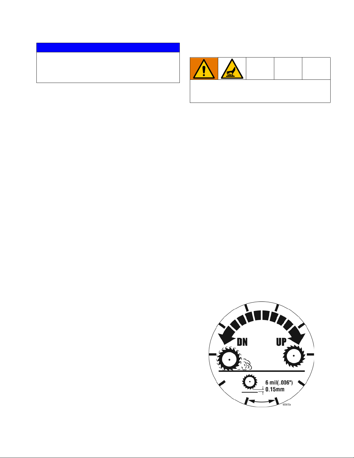
NOTE: Each increment on Drum Adjustment Dial (D) is
0.006 in. (0.15 mm) depth change of cutting drum.
3A5578C 17
Operation
Stop Cutting Material
1. Raise Drum Engage Lever so that the drum is off
the ground.
2. Slide Engine Throttle to low setting.
3. Depress Engine Kill Button and turn Engine Power
Switch to “OFF”.
4. Clean the entire exterior of the machine after it has
cooled. Check for worn or damaged parts and
perform any required DCS Instructions on page
19.
18 3A5578C

Operation
DCS Instructions
Each time the DCS Control is turned on, the DCS actuator will travel to the Home position.
Once the DCS Control finds Home, ensure the current
model is selected as well as your desired language and
units. See Menu Screens, page 13, for instructions on
changing these settings.
Set Zero Point:
Lower the Depth Control Wheels to the surface by using
the Drum Engage Lever to unlatch the drum housing
from the “up” position. With the engine on, lower the
drum by pressing the Down Arrow Button until you hear
the cutters make contact with the pavement surface.
Hold down the Zero Button for 2 seconds. Your Zero
Point has now been saved.
NOTE: The Cut Depth Target is based off of the Zero
Point. Re-program the Zero Point if the drum is changed
or worn.
Set Cut Depth Target:
Quick press the Zero Button to take the drum to the
pavement surface. Set the Cut Depth Target by:
1. Quick pressing the Down Arrow Button as many
times as needed to achieve your target. Then long
press the Cut Depth Button to save your target.
NOTE: This method will lower the cutting drum into
the pavement surface as you set your cut depth.
OR
2. From the Zero Point, long press the Cut Depth Button until a new screen pops up. Use the Down
Arrow Button to enter your Cut Depth Target. Then
long press the Cut Depth Button to save your target
and return to the Run Screen.
NOTE: This method will keep the cutting drum stationary as you set your Cut Depth Target.
3A5578C 19
Operation
The DCS Control is now ready to grind/scarify. Long
press down on the Handlebar Rocker Switch to lower
the drum to your Cut Depth Target. Short press up or
down on the switch to adjust your Cut Depth on the fly.
When finished with your cut, long press up on the switch
to raise the drum to the Home position.
NOTE: The Zero Point and Cut Depth are referenced
from the Home position. Recalibrate your DCS Control
periodically by pressing the Home button or long pressing up on the Handlebar Rocker Switch.
NOTE: Pressing any button while the drum is moving to
Zero or Cut Depth will stop the command and halt the
drum from moving any further up or down until another
button is pressed.
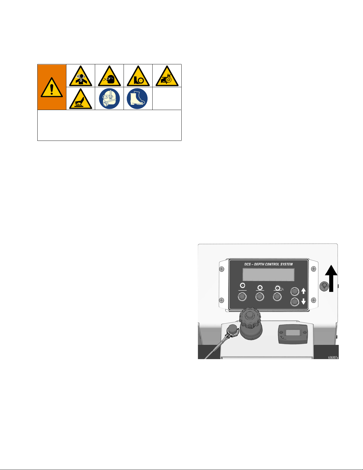
Manual Height Adjustment
If the DCS Control is not usable (dead battery, etc.), the
drum height can be adjusted using the Manual Height
Adjustment feature.
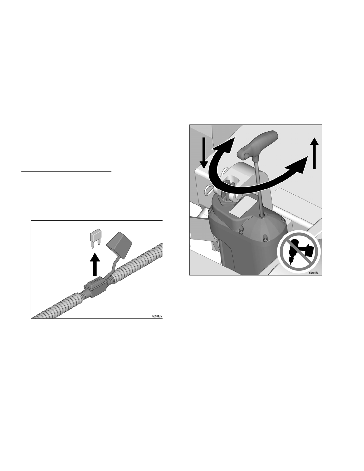
1. Remove fuse from fuse holder near positive battery
terminal. This will protect the battery from damage.
3. Insert 6mm hex key into the port the screw plug was
removed from.
- One revolution of the hex key results in 1/8”
(3mm, 125 mil) of adjustment at the cutter drum.
- Rotate counterclockwise to lower the drum;
rotate clockwise to raise the drum. Max rota-
tion speed of 1 revolution per second. Do
not use power tools in the Manual Height
Adjustment port.
4. Once the desired depth is achieved, replace the
screw plug in order to keep water and dust out.
2. Use a 6mm hex key to remove the screw plug on
the top of the linear actuator.
20 3A5578C

Maintenance
Avoid touching engine and drum after use until they
have completely cooled. To avoid unexpected start
up, disconnect spark plug wire before you service
your unit.
The following steps should be performed to maintain
proper operation and sustain the life of the GrindLazer.
BEFORE OPERATION:
• Visually inspect the entire unit for damage or loose
connections.
• Check engine oil (see engine manual).
Maintenance
AFTER THE FIRST 20 HOURS OF
OPERATION:
• Drain engine oil and refill with clean oil. See engine
manual for correct viscosity.
EVERY 40-50 HOURS OF OPERATION:
• Change engine oil (see engine manual).
• Grease wheel bearings.
• Inspect and change drum bushings and shafts.
AS REQUIRED:
• Check drive belt and tension and tighten or replace
as needed.
• Check drum bushings and cutters.
• Check drum for uneven wear.
DAILY:
• Check all fasteners and re-tighten.
• Clean dust and debris from exterior of unit (do NOT
use pressure washer or other high pressure
cleaning equipment).
• Inspect dust skirts for damage. Repair or replace
damaged skirts in order to help dust and debris
containment.
• Check engine oil level and fill as necessary.
• Check and fill gas tank.
• Remove air filter cover and clean element. Replace
element if necessary. Replacement elements can
be purchased from your local engine dealer.
Pro Models:
• Grease the cam lever and lower linkage.
For additional information about engine maintenance,
see engine manual.
3A5578C 21
 Loading...