

Graco GrindLazer 25M843, GrindLazer 25M842, GrindLazer 25N667, GrindLazer 25M846, GrindLazer 25N668 Operation - Repair - Parts
Page 1
www.graco.com/techsupport
?? ??
Operation, Repair, Parts
GrindLazer Standard Series
GrindLazer Pro Series
™
GrindLazer
For removal of materials from flat horizontal concrete and asphalt surfaces. For
professional use only.
Standard Series - Forward Cut
Model 25M842 - GrindLazer Standard DC87 G (200 cc / 6.5hp)
Model 25M843 - GrindLazer Standard DC89 G (270 cc / 9hp)
Pro Series - Forward Cut
Model 25M846 - GrindLazer Pro DC1013 G (390 cc / 13hp)
Model 25N667 - GrindLazer Pro DC89 G (270 cc / 9hp)
Model 25N668 - GrindLazer Pro DC1013 DCS (390 cc / 13hp Electric Start)
3A5578C
EN
Page 2

Contents
Contents
Warnings . . . . . . . . . . . . . . . . . . . . . . . . . . . . . . . . . . . . . . . . . . . . . . . . . . . . . . . . . . . . . . . . . . . . . . . . . . . . . . . . . . . . . . . . . . . . . . . . . . . . . . . . . . . . 3
Component Identification . . . . . . . . . . . . . . . . . . . . . . . . . . . . . . . . . . . . . . . . . . . . . . . . . . . . . . . . . . . . . . . . . . . . . . . . . . . . . . . . . . . . . . . . . . . . . . . 5
GrindLazer Standard Series Models . . . . . . . . . . . . . . . . . . . . . . . . . . . . . . . . . . . . . . . . . . . . . . . . . . . . . . . . . . . . . . . . . . . . . . . . . . . . . . . . . . . 5
GrindLazer Pro Series Models . . . . . . . . . . . . . . . . . . . . . . . . . . . . . . . . . . . . . . . . . . . . . . . . . . . . . . . . . . . . . . . . . . . . . . . . . . . . . . . . . . . . . . . . 6
GrindLazer Pro Series DCS Models . . . . . . . . . . . . . . . . . . . . . . . . . . . . . . . . . . . . . . . . . . . . . . . . . . . . . . . . . . . . . . . . . . . . . . . . . . . . . . . . . . . . 7
Setup . . . . . . . . . . . . . . . . . . . . . . . . . . . . . . . . . . . . . . . . . . . . . . . . . . . . . . . . . . . . . . . . . . . . . . . . . . . . . . . . . . . . . . . . . . . . . . . . . . . . . . . . . . . . . . . 8
Handle Bar Adjustment (Pro Models Only) . . . . . . . . . . . . . . . . . . . . . . . . . . . . . . . . . . . . . . . . . . . . . . . . . . . . . . . . . . . . . . . . . . . . . . . . . . . . . . . 8
Engine Kill Button . . . . . . . . . . . . . . . . . . . . . . . . . . . . . . . . . . . . . . . . . . . . . . . . . . . . . . . . . . . . . . . . . . . . . . . . . . . . . . . . . . . . . . . . . . . . . . . . . . 8
Drum Installation/Replacement for GrindLazer Standard Series Models . . . . . . . . . . . . . . . . . . . . . . . . . . . . . . . . . . . . . . . . . . . . . . . . . . . . . . . . 8
Drum Installation/Replacement for GrindLazer Pro Series Models . . . . . . . . . . . . . . . . . . . . . . . . . . . . . . . . . . . . . . . . . . . . . . . . . . . . . . . . . . . . 9
Vacuum Attachment . . . . . . . . . . . . . . . . . . . . . . . . . . . . . . . . . . . . . . . . . . . . . . . . . . . . . . . . . . . . . . . . . . . . . . . . . . . . . . . . . . . . . . . . . . . . . . . 10
DCS Control (DCS Models only) . . . . . . . . . . . . . . . . . . . . . . . . . . . . . . . . . . . . . . . . . . . . . . . . . . . . . . . . . . . . . . . . . . . . . . . . . . . . . . . . . . . . . 11
Operation . . . . . . . . . . . . . . . . . . . . . . . . . . . . . . . . . . . . . . . . . . . . . . . . . . . . . . . . . . . . . . . . . . . . . . . . . . . . . . . . . . . . . . . . . . . . . . . . . . . . . . . . . . . 15
Machine Start Up . . . . . . . . . . . . . . . . . . . . . . . . . . . . . . . . . . . . . . . . . . . . . . . . . . . . . . . . . . . . . . . . . . . . . . . . . . . . . . . . . . . . . . . . . . . . . . . . . 15
Cutting Material . . . . . . . . . . . . . . . . . . . . . . . . . . . . . . . . . . . . . . . . . . . . . . . . . . . . . . . . . . . . . . . . . . . . . . . . . . . . . . . . . . . . . . . . . . . . . . . . . . 16
Cutting Drum Assemblies . . . . . . . . . . . . . . . . . . . . . . . . . . . . . . . . . . . . . . . . . . . . . . . . . . . . . . . . . . . . . . . . . . . . . . . . . . . . . . . . . . . . . . . . . . . 17
Stop Cutting Material . . . . . . . . . . . . . . . . . . . . . . . . . . . . . . . . . . . . . . . . . . . . . . . . . . . . . . . . . . . . . . . . . . . . . . . . . . . . . . . . . . . . . . . . . . . . . . 18
DCS Instructions . . . . . . . . . . . . . . . . . . . . . . . . . . . . . . . . . . . . . . . . . . . . . . . . . . . . . . . . . . . . . . . . . . . . . . . . . . . . . . . . . . . . . . . . . . . . . . . . . . 19
Maintenance . . . . . . . . . . . . . . . . . . . . . . . . . . . . . . . . . . . . . . . . . . . . . . . . . . . . . . . . . . . . . . . . . . . . . . . . . . . . . . . . . . . . . . . . . . . . . . . . . . . . . . . . 21
DCS Control Translations . . . . . . . . . . . . . . . . . . . . . . . . . . . . . . . . . . . . . . . . . . . . . . . . . . . . . . . . . . . . . . . . . . . . . . . . . . . . . . . . . . . . . . . . . . . . . 22
Repair . . . . . . . . . . . . . . . . . . . . . . . . . . . . . . . . . . . . . . . . . . . . . . . . . . . . . . . . . . . . . . . . . . . . . . . . . . . . . . . . . . . . . . . . . . . . . . . . . . . . . . . . . . . . . . 24
Drum Replacement for GrindLazer Standard Series Models . . . . . . . . . . . . . . . . . . . . . . . . . . . . . . . . . . . . . . . . . . . . . . . . . . . . . . . . . . . . . . . . 24
Drum Replacement for GrindLazer Pro Series Models . . . . . . . . . . . . . . . . . . . . . . . . . . . . . . . . . . . . . . . . . . . . . . . . . . . . . . . . . . . . . . . . . . . . 24
Belt Replacement (Standard Models) . . . . . . . . . . . . . . . . . . . . . . . . . . . . . . . . . . . . . . . . . . . . . . . . . . . . . . . . . . . . . . . . . . . . . . . . . . . . . . . . . . 25
Belt Replacement (Pro Models) . . . . . . . . . . . . . . . . . . . . . . . . . . . . . . . . . . . . . . . . . . . . . . . . . . . . . . . . . . . . . . . . . . . . . . . . . . . . . . . . . . . . . . 27
Belt Alignment . . . . . . . . . . . . . . . . . . . . . . . . . . . . . . . . . . . . . . . . . . . . . . . . . . . . . . . . . . . . . . . . . . . . . . . . . . . . . . . . . . . . . . . . . . . . . . . . . . . 29
Bearing Replacement (Standard Models) . . . . . . . . . . . . . . . . . . . . . . . . . . . . . . . . . . . . . . . . . . . . . . . . . . . . . . . . . . . . . . . . . . . . . . . . . . . . . . 29
Bearing Replacement (Pro Models) . . . . . . . . . . . . . . . . . . . . . . . . . . . . . . . . . . . . . . . . . . . . . . . . . . . . . . . . . . . . . . . . . . . . . . . . . . . . . . . . . . . 30
Diamond (High Speed) Kit Installation (Pro Models Only) . . . . . . . . . . . . . . . . . . . . . . . . . . . . . . . . . . . . . . . . . . . . . . . . . . . . . . . . . . . . . . . . . . 32
Troubleshooting . . . . . . . . . . . . . . . . . . . . . . . . . . . . . . . . . . . . . . . . . . . . . . . . . . . . . . . . . . . . . . . . . . . . . . . . . . . . . . . . . . . . . . . . . . . . . . . . . . . . . 33
DCS Models only . . . . . . . . . . . . . . . . . . . . . . . . . . . . . . . . . . . . . . . . . . . . . . . . . . . . . . . . . . . . . . . . . . . . . . . . . . . . . . . . . . . . . . . . . . . . . . . . . 34
DCS Error Codes . . . . . . . . . . . . . . . . . . . . . . . . . . . . . . . . . . . . . . . . . . . . . . . . . . . . . . . . . . . . . . . . . . . . . . . . . . . . . . . . . . . . . . . . . . . . . . . . . 35
DCS Actuator Rod Does Not Move . . . . . . . . . . . . . . . . . . . . . . . . . . . . . . . . . . . . . . . . . . . . . . . . . . . . . . . . . . . . . . . . . . . . . . . . . . . . . . . . . . . 37
Parts . . . . . . . . . . . . . . . . . . . . . . . . . . . . . . . . . . . . . . . . . . . . . . . . . . . . . . . . . . . . . . . . . . . . . . . . . . . . . . . . . . . . . . . . . . . . . . . . . . . . . . . . . . . . . . . 38
Drive Assembly (25M842) . . . . . . . . . . . . . . . . . . . . . . . . . . . . . . . . . . . . . . . . . . . . . . . . . . . . . . . . . . . . . . . . . . . . . . . . . . . . . . . . . . . . . . . . . . 38
Drive Assembly Parts List (25M842) . . . . . . . . . . . . . . . . . . . . . . . . . . . . . . . . . . . . . . . . . . . . . . . . . . . . . . . . . . . . . . . . . . . . . . . . . . . . . . . . . . 39
Drive Assembly (25M843) . . . . . . . . . . . . . . . . . . . . . . . . . . . . . . . . . . . . . . . . . . . . . . . . . . . . . . . . . . . . . . . . . . . . . . . . . . . . . . . . . . . . . . . . . . 40
Drive Assembly Parts List (25M843) . . . . . . . . . . . . . . . . . . . . . . . . . . . . . . . . . . . . . . . . . . . . . . . . . . . . . . . . . . . . . . . . . . . . . . . . . . . . . . . . . . 41
Guide Bar Assembly (25M842 and 25M843) . . . . . . . . . . . . . . . . . . . . . . . . . . . . . . . . . . . . . . . . . . . . . . . . . . . . . . . . . . . . . . . . . . . . . . . . . . . . 42
Guide Bar Assembly (25M842 and 25M843) Parts List . . . . . . . . . . . . . . . . . . . . . . . . . . . . . . . . . . . . . . . . . . . . . . . . . . . . . . . . . . . . . . . . . . . . 43
Primary Housing Assembly (25M842 and 25M843) . . . . . . . . . . . . . . . . . . . . . . . . . . . . . . . . . . . . . . . . . . . . . . . . . . . . . . . . . . . . . . . . . . . . . . . 44
Primary Housing Assembly (25M842 and 25M843) Parts List . . . . . . . . . . . . . . . . . . . . . . . . . . . . . . . . . . . . . . . . . . . . . . . . . . . . . . . . . . . . . . . 45
Drum Housing Assembly (25M842 and 25M843) . . . . . . . . . . . . . . . . . . . . . . . . . . . . . . . . . . . . . . . . . . . . . . . . . . . . . . . . . . . . . . . . . . . . . . . . . 46
Drum Housing Assembly (25M842 and 25M843) Parts List . . . . . . . . . . . . . . . . . . . . . . . . . . . . . . . . . . . . . . . . . . . . . . . . . . . . . . . . . . . . . . . . . 46
Bearing and Shaft Assembly (25M846, 25N667 & 25N668) . . . . . . . . . . . . . . . . . . . . . . . . . . . . . . . . . . . . . . . . . . . . . . . . . . . . . . . . . . . . . . . . 47
Bearing and Shaft Assembly (25M846, 25N667 & 25N668) Parts List . . . . . . . . . . . . . . . . . . . . . . . . . . . . . . . . . . . . . . . . . . . . . . . . . . . . . . . . 47
Rear Assembly (25M846 & 25N667) . . . . . . . . . . . . . . . . . . . . . . . . . . . . . . . . . . . . . . . . . . . . . . . . . . . . . . . . . . . . . . . . . . . . . . . . . . . . . . . . . . 48
Rear Assembly (25M846 & 25N667) Parts List . . . . . . . . . . . . . . . . . . . . . . . . . . . . . . . . . . . . . . . . . . . . . . . . . . . . . . . . . . . . . . . . . . . . . . . . . . 49
Rear Assembly (25N668) . . . . . . . . . . . . . . . . . . . . . . . . . . . . . . . . . . . . . . . . . . . . . . . . . . . . . . . . . . . . . . . . . . . . . . . . . . . . . . . . . . . . . . . . . . . 50
Rear Assembly (25N668) Parts List . . . . . . . . . . . . . . . . . . . . . . . . . . . . . . . . . . . . . . . . . . . . . . . . . . . . . . . . . . . . . . . . . . . . . . . . . . . . . . . . . . . 51
Damper Assembly (25M846, 25N667) . . . . . . . . . . . . . . . . . . . . . . . . . . . . . . . . . . . . . . . . . . . . . . . . . . . . . . . . . . . . . . . . . . . . . . . . . . . . . . . . . 52
Damper Assembly (25M846 & 25N667) Parts List . . . . . . . . . . . . . . . . . . . . . . . . . . . . . . . . . . . . . . . . . . . . . . . . . . . . . . . . . . . . . . . . . . . . . . . . 52
Front Assembly (25M846, 25N667 & 25N668) . . . . . . . . . . . . . . . . . . . . . . . . . . . . . . . . . . . . . . . . . . . . . . . . . . . . . . . . . . . . . . . . . . . . . . . . . . . 54
Front Assembly (25M846, 25N667 & 25N668) Parts List . . . . . . . . . . . . . . . . . . . . . . . . . . . . . . . . . . . . . . . . . . . . . . . . . . . . . . . . . . . . . . . . . . . 55
Handle Bar Assembly (25M846) . . . . . . . . . . . . . . . . . . . . . . . . . . . . . . . . . . . . . . . . . . . . . . . . . . . . . . . . . . . . . . . . . . . . . . . . . . . . . . . . . . . . . . 56
Handle Bar Assembly (25M846) Parts List . . . . . . . . . . . . . . . . . . . . . . . . . . . . . . . . . . . . . . . . . . . . . . . . . . . . . . . . . . . . . . . . . . . . . . . . . . . . . . 56
Handle Bar Assembly (25N668) . . . . . . . . . . . . . . . . . . . . . . . . . . . . . . . . . . . . . . . . . . . . . . . . . . . . . . . . . . . . . . . . . . . . . . . . . . . . . . . . . . . . . . 57
Handle Bar Assembly (25N668) Parts List . . . . . . . . . . . . . . . . . . . . . . . . . . . . . . . . . . . . . . . . . . . . . . . . . . . . . . . . . . . . . . . . . . . . . . . . . . . . . . 57
Drive Assembly (25M846 & 25N667) . . . . . . . . . . . . . . . . . . . . . . . . . . . . . . . . . . . . . . . . . . . . . . . . . . . . . . . . . . . . . . . . . . . . . . . . . . . . . . . . . . 58
Drive Assembly (25M846 & 25N667) Parts List . . . . . . . . . . . . . . . . . . . . . . . . . . . . . . . . . . . . . . . . . . . . . . . . . . . . . . . . . . . . . . . . . . . . . . . . . . 59
Drive Assembly (25N668) . . . . . . . . . . . . . . . . . . . . . . . . . . . . . . . . . . . . . . . . . . . . . . . . . . . . . . . . . . . . . . . . . . . . . . . . . . . . . . . . . . . . . . . . . . . 60
Drive Assembly (25N668) Parts List . . . . . . . . . . . . . . . . . . . . . . . . . . . . . . . . . . . . . . . . . . . . . . . . . . . . . . . . . . . . . . . . . . . . . . . . . . . . . . . . . . . 61
DCS Control Box 18A790 . . . . . . . . . . . . . . . . . . . . . . . . . . . . . . . . . . . . . . . . . . . . . . . . . . . . . . . . . . . . . . . . . . . . . . . . . . . . . . . . . . . . . . . . . . . . . . 62
25N668 only . . . . . . . . . . . . . . . . . . . . . . . . . . . . . . . . . . . . . . . . . . . . . . . . . . . . . . . . . . . . . . . . . . . . . . . . . . . . . . . . . . . . . . . . . . . . . . . . . . . . . 62
Parts List . . . . . . . . . . . . . . . . . . . . . . . . . . . . . . . . . . . . . . . . . . . . . . . . . . . . . . . . . . . . . . . . . . . . . . . . . . . . . . . . . . . . . . . . . . . . . . . . . . . . . . . . 62
Wiring Diagram . . . . . . . . . . . . . . . . . . . . . . . . . . . . . . . . . . . . . . . . . . . . . . . . . . . . . . . . . . . . . . . . . . . . . . . . . . . . . . . . . . . . . . . . . . . . . . . . . . . . . . 63
DCS System . . . . . . . . . . . . . . . . . . . . . . . . . . . . . . . . . . . . . . . . . . . . . . . . . . . . . . . . . . . . . . . . . . . . . . . . . . . . . . . . . . . . . . . . . . . . . . . . . . . . . 63
DCS Control Box . . . . . . . . . . . . . . . . . . . . . . . . . . . . . . . . . . . . . . . . . . . . . . . . . . . . . . . . . . . . . . . . . . . . . . . . . . . . . . . . . . . . . . . . . . . . . . . . . 64
Technical Data . . . . . . . . . . . . . . . . . . . . . . . . . . . . . . . . . . . . . . . . . . . . . . . . . . . . . . . . . . . . . . . . . . . . . . . . . . . . . . . . . . . . . . . . . . . . . . . . . . . . . . . 65
CALIFORNIA PROPOSITION 65 . . . . . . . . . . . . . . . . . . . . . . . . . . . . . . . . . . . . . . . . . . . . . . . . . . . . . . . . . . . . . . . . . . . . . . . . . . . . . . . . . . . . . 66
Graco Standard Warranty . . . . . . . . . . . . . . . . . . . . . . . . . . . . . . . . . . . . . . . . . . . . . . . . . . . . . . . . . . . . . . . . . . . . . . . . . . . . . . . . . . . . . . . . . . . . . . 67
2 3A5578C
Page 3
Warnings
WARNING
Warnings
The following warnings are for the setup, use, grounding, maintenance, and repair of this equipment. The exclamation
point symbol alerts you to a general warning and the hazard symbols refer to procedure-specific risks. When these
symbols appear in the body of this manual or on warning labels, refer back to these Warnings. Product-specific hazard
symbols and warnings not covered in this section may appear throughout the body of this manual where applicable.
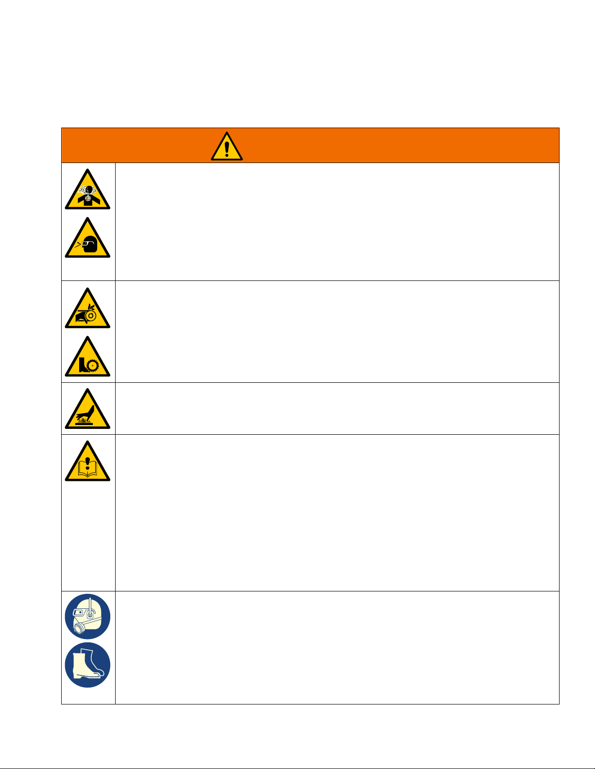
DUST AND DEBRIS HAZARD
Grinding concrete and other surfaces with this equipment can create dust that contains hazardous
substances. Grinding can also create flying debris.
To reduce the risk of serious injury:
• Control the dust to meet all applicable workplace regulations.
• Wear protective eye wear and a properly fit-tested and government approved respirator suitable for
the dust conditions.
• Use equipment only in a well-ventilated area.
• Grinding equipment must be used only by trained personnel who understand the applicable workplace regulations.
ENTANGLEMENT AND ROTATING PARTS HAZARD
Rotating parts can cut or amputate fingers and other body parts.
• Keep clear of rotating parts.
• Do not operate equipment with protective guards or covers removed.
• Do not wear loose clothing, jewelry or long hair while operating equipment.
• Before checking, moving, or servicing equipment, disable power supply.
BURN HAZARD
Cutters and engine can become very hot during operation. To avoid severe burns, do not touch hot
equipment. Wait until equipment has cooled completely.
EQUIPMENT MISUSE HAZARD
Misuse can cause death or serious injury.
• Do not operate the unit when fatigued or under the influence of drugs or alcohol.
• Do not leave the work area while equipment is energized. Turn off all equipment when equipment
is not in use.
• Check equipment daily. Repair or replace worn or damaged parts immediately with genuine manufacturer’s replacement parts only.
• Do not alter or modify equipment.
• Use equipment only for its intended purpose. Call your distributor for information.
• Keep children and animals away from work area.
• Comply with all applicable safety regulations.
• Maintain a safe operating distance from other people in the work area.
• Avoid any pipes, columns, openings, or any other objects protruding from work surface.
PERSONAL PROTECTIVE EQUIPMENT
You must wear appropriate protective equipment when operating, servicing, or when in the operating
area of the equipment to help protect you from serious injury, including eye injury, inhalation of dust or
chemicals, burns, and hearing loss. This equipment includes but is not limited to:
• Protective eye wear.
• Protective shoes.
• Gloves.
• Hearing protection.
• Properly fit-tested and government approved respirator suitable for the dust conditions.
3A5578C 3
Page 4
Warnings
WARNING
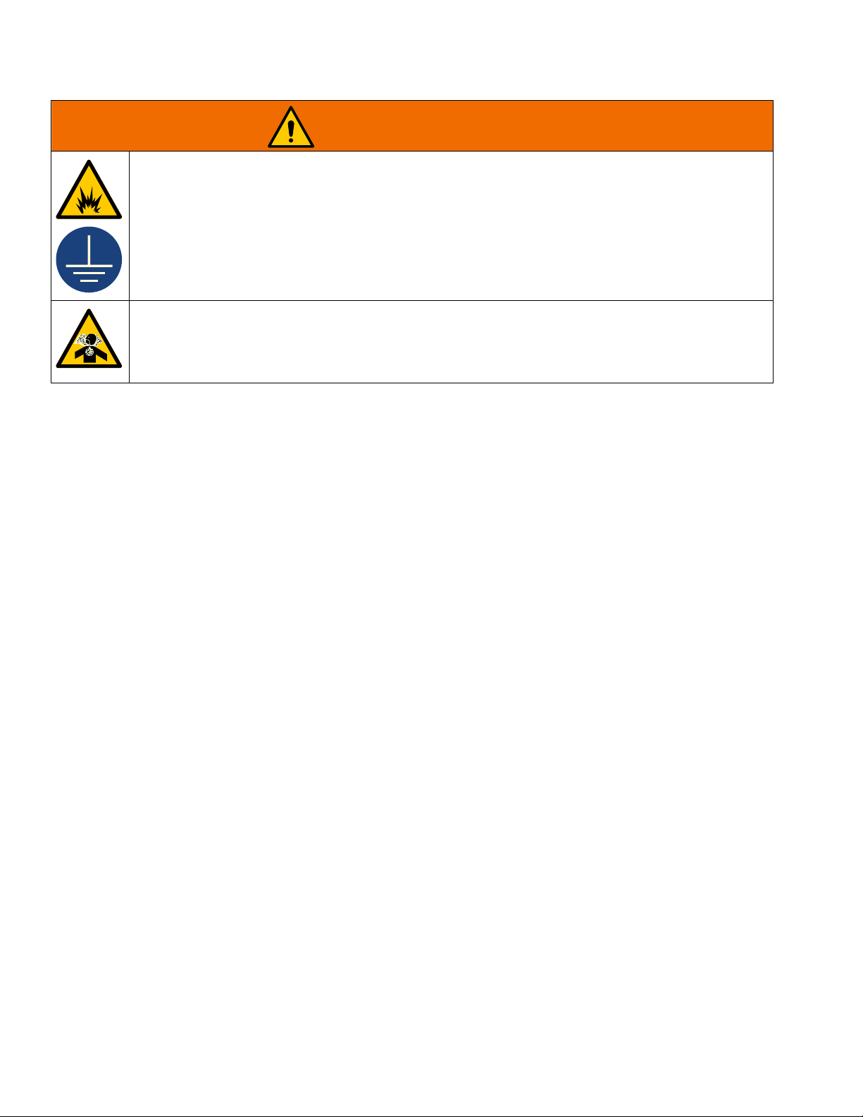
FIRE AND EXPLOSION HAZARD
Flammable fumes, such as solvent and paint fumes, in work area can ignite or explode. To help prevent fire and explosion:
• Use equipment only in well ventilated area.
• Do not fill fuel tank while engine is running or hot; shut off engine and let it cool. Fuel is flammable
and can ignite or explode if spilled on hot surface.
• Keep work area free of debris, including solvent, rags and gasoline.
• Keep a fire extinguisher in work area.
CARBON MONOXIDE HAZARD
Exhaust contains poisonous carbon monoxide, which is colorless and odorless. Breathing carbon
monoxide can cause death.
• Do not operate in an enclosed area.
4 3A5578C
Page 5
Component Identification
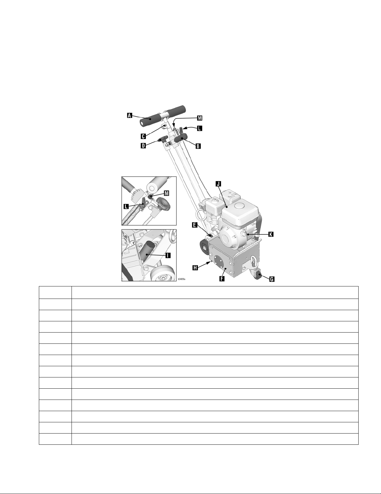
GrindLazer Standard Series Models
Component Identification
A Handlebar
B Depth Engage Lever (coarse adjustment)
C Locking Nut (for handle height adjustment)
D Drum Adjustment Dial (fine adjustments)
E Fixed Front Wheel (optional)
F Drum Access Panel
G Feathering Front Wheel
HDust Skirt
I Vacuum Port
JEngine
K Engine Power Switch
L Engine Throttle
M Engine Kill Button
Component
3A5578C 5
Page 6
Component Identification
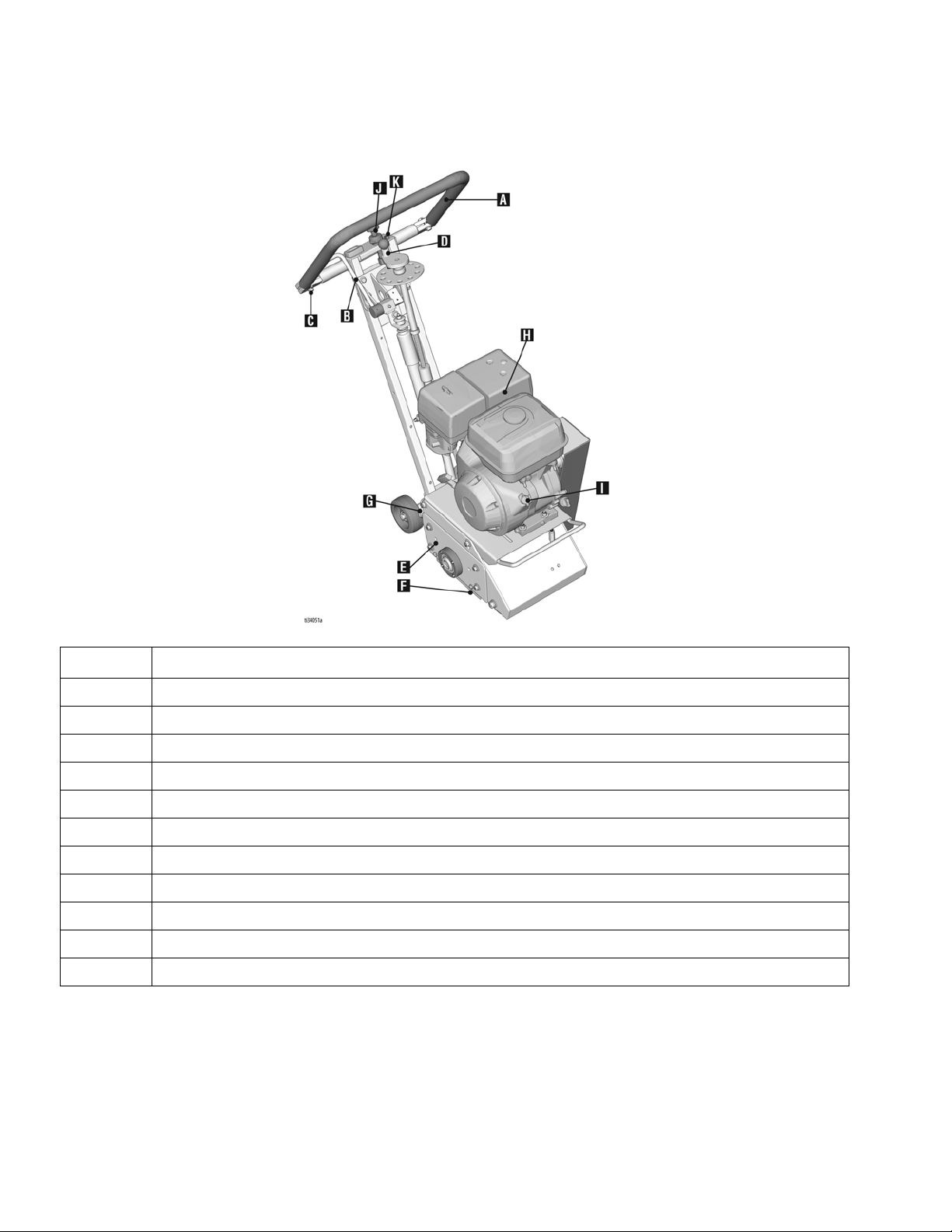
GrindLazer Pro Series Models
A Handlebar
B Drum Engage Lever
C Handlebar Adjustment Bolts
D Drum Adjustment Dial
E Drum Access Panel
FDust Skirt
G Vacuum Port
HEngine
I Engine Power Switch
J Engine Throttle
K Engine Kill Button
Component
6 3A5578C
Page 7

GrindLazer Pro Series DCS Models
Component Identification
Component
A Handlebar
BPower Switch
C Handlebar Adjustment Bolts
D DCS Control
E Pressure Control Dial
FDust Skirt
GVacuum Port
HEngine
I Electric Start Engine Switch
J Engine Throttle
3A5578C 7
K Engine Kill Button
L Pressure Indicator
M Wheel Stop
N Hour Meter/Tachometer
S Home Button
T Zero Button
U Cut Depth Button
V Up/Down Buttons
W Manual Height Adjustment
Component
Page 8
Setup
Setup
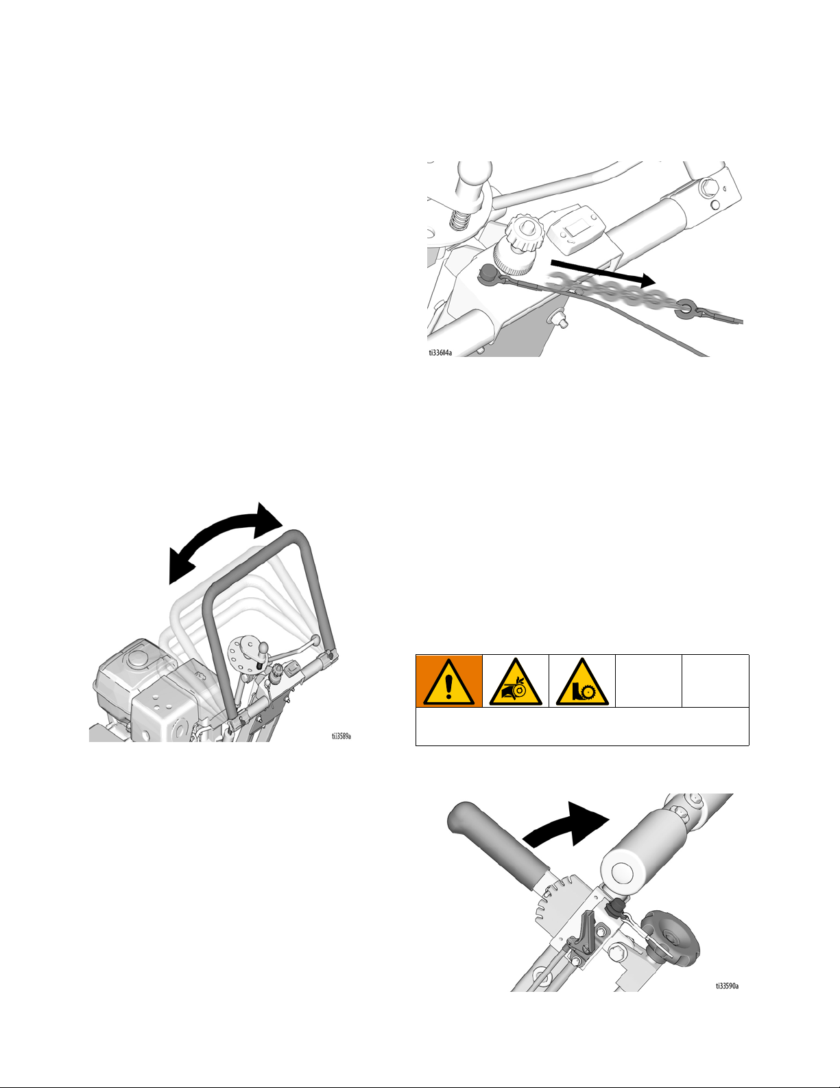
Handle Bar Adjustment (Pro Models Only)
The handlebars are equipped with a high-density
vibration suppression material to reduce operator fatigue
when operating equipment. To adjust the handlebars to
a new position for different height operators please follow
these steps:
1. Using a 9/16” (14mm) wrench or socket, loosen the
bolts on both sides of the handlebars until the
handlebar moves freely.
2. Stand behind the machine and lightly tap the
handlebar to the desired position.
3. Re-tighten the bolts to 260-300 in-lb (29-34 N•m) to
lock the handlebars into position.
NOTE: Never operate equipment with loose handlebars.
The bolts must be fastened tightly assuring the handle is
locked into position.
stopped by pressing down on the Engine Kill Button.
Drum Installation/Replacement for GrindLazer Standard Series Models
Normal use will require periodic drum inspection and
may necessitate drum replacement. Time of
replacement will vary according to usage and load
factors.
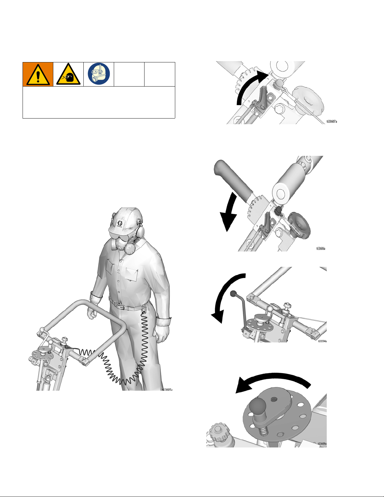
Engine Kill Button
In the event of a malfunction or an accident (such as the
machine operator falling or losing footing), the
GrindLazer is equipped with a corded Engine Kill Button.
Attach the end of the cord to the operator’s belt or wrist,
and snap the clip into place on the button by raising the
top of the Engine Kill Button and inserting the clip into the
gap. If the operator becomes distanced too far from the
machine, the cord will detach from the button and the
machine will stop running. The engine can also be
Tools needed:
1. 17mm socket or wrench
2. Rubber mallet
To avoid injury from unexpected start up, disconnect
spark plug wire before you service your unit.
1. Raise the Drum Engage Lever to the up position so
the cutter drum is off the ground.
8 3A5578C
Page 9
Setup
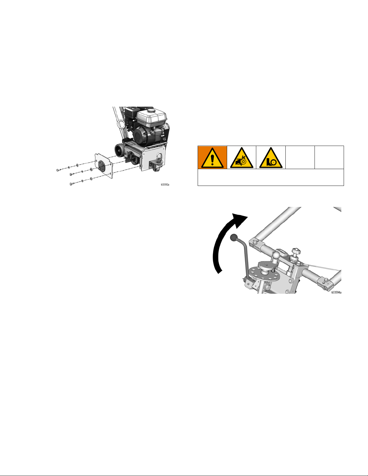
2. Remove the three hex head cap screws from the
Drum Access Panel using the 17mm socket or
wrench.
3. Remove Drum Access Panel (this may require the
rubber mallet to break it loose).
4. Slide out drum assembly (use caution as it is
heavy).
5. Once the cutter drum is removed, take to a
workbench for assembly.
a. Inspect condition of cutters, spacers, shafts,
bushings and drum.
Drum Installation/Replacement for GrindLazer Pro Series Models
Normal use will require periodic drum inspection and
may necessitate drum replacement. Time of
replacement will vary according to usage and load
factors. Tools needed:
1. 9/16” socket or wrench.
2. Rubber mallet.
To avoid injury from unexpected start up, disconnect
spark plug wire before you service your unit.
1. Raise the Drum Engage Lever to the up position so
the cutter drum is off the ground.
6. Before replacing the drum onto hex shaft:
a. Check that all bearings are in good working
order.
b. Remove dirt and material build-up from inside
drive carriage and drum.
c. Lube all metal contacts.
7. Align and slide drum back onto the hex shaft.
8. Replace Drum Access Panel (lift up and lock into
place) over hex shaft and secure hardware.
NOTE: An extra drum loaded with cutters for rapid job
site replacement is recommended.
2. Remove the four hex head cap screws from the
Drum Access Panel using the 9/16” socket or
wrench.
3. Remove the Drum Access Panel (this may require
the rubber mallet to break it loose).
3A5578C 9
Page 10
Setup
4. Slide out drum assembly (use caution as it is
heavy).
5. Once the cutter drum is removed take to a
workbench for assembly.
a. Inspect condition of cutters, spacers, shafts,
bushings and drum.
6. Before replacing the drum onto hex shaft:
a. Check that all bearings are in good working
order.
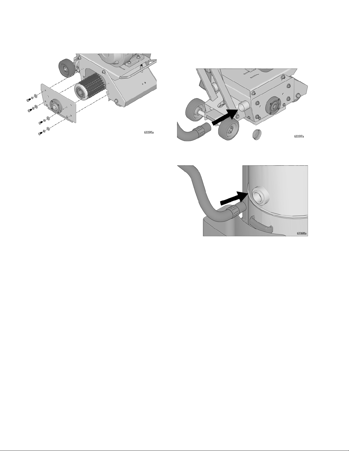
Vacuum Attachment
1. If using a vacuum, attach vacuum hose to the
Vacuum Port.
2. Attach vacuum hose to the Inlet Port on the Cyclone
Separator (optional) or vacuum. \
b. Remove dirt and material build-up from inside
drive carriage and drum.
c. Lube all metal contacts.
7. Align and slide drum back onto the hex shaft.
8. Replace Drum Access Panel (lift up and lock into
place) over hex shaft and secure hardware.
NOTE: An extra drum loaded with cutters for rapid job
site replacement is recommended.
10 3A5578C
Page 11
DCS Control (DCS Models only)
Setup
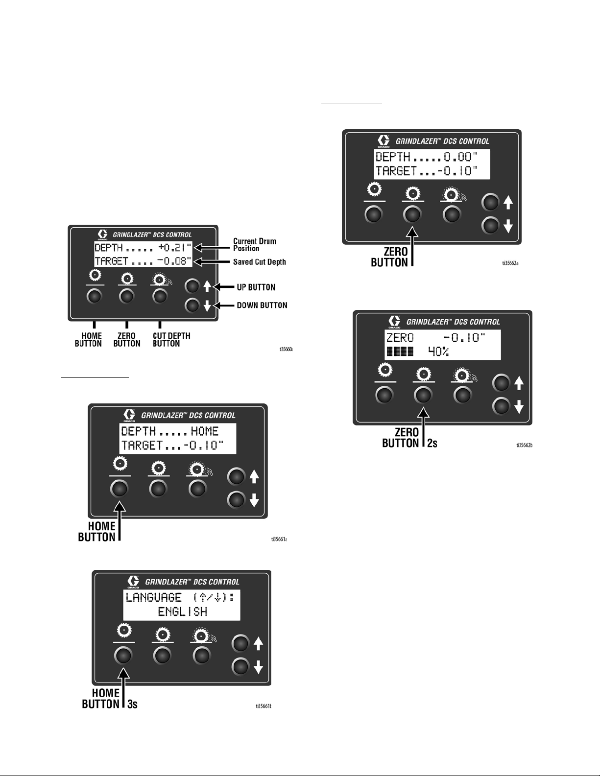
Buttons on the DCS Control have two functions, quick
press and long press. Quick press refers to pressing the
button and releasing the button quickly, while long press
is pressing the button and holding the button for two or
more seconds.
NOTE: “+” (plus) refers to above pavement surface. “-”
(minus) refers to below pavement surface.
Run Screen
Home Button
Zero Button
Quick Press: Takes the drum to the surface.
Long Press: Reprograms the zero point to the current
drum position.
Quick Press: Takes the drum to its highest position.
Long Press: Brings up Menu Screen.
3A5578C 11
Page 12

Setup
Cut Depth Button
Quick Press:
Long Press:
- If at or above zero point: Opens new screen to
select desired cut depth using up/down buttons.
- If below zero point: Reprograms the Cut Depth
Target to the current drum position.
Takes the drum to the Cut Depth Target.
•To exit without saving, quick press the Cut
Depth Button.
•To exit with saving, long press the Cut Depth
Button.
Up Arrow Button*
Quick Press: Raises the drum by 0.01” (0.25mm, 10
mil).
Long Press: Raises the drum to Home position.
Down Arrow Button*
Quick Press: Lowers the drum by 0.01” (25mm, 10
mil).
Long Press: Lowers the drum to Cut Depth Target.
*Handlebar Rocker Switch has the same functions as
Up and Down Arrow Buttons.
12 3A5578C
Page 13
Setup
Menu Screens
To display the Menu Screens, hold down Home Button
from the Run Screen. To save menu settings and return
to Run Screen, hold down Home Button from any Menu
Screen.
To cycle through selections in each Menu Screen, use
Up and Down Arrow Buttons.
To advance to next Menu Screen, quick press the Home
Button.
Menu Screen #1 - Language
Select your desired language (English, Spanish,
French, German, or International Symbols).
Menu Screen #3 - Model Select
Your GrindLazer model name can be found on the handlebar dashboard label. Select the model on the DCS
Control which matches the model you have. This
ensures accurate depth readings. Hold down Up or
Down Arrow Buttons to cycle through models.
Menu Screen #4 - Software revision
Displays the revision of the software on the DCS Control.
Menu Screen #2 - Units
Select your desired depth units (inches, millimeters, or
mils).
3A5578C 13
Page 14
Setup
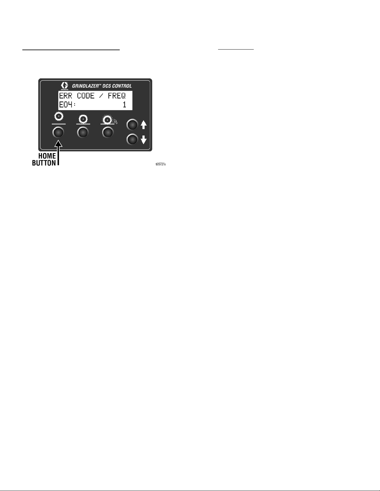
Menu Screen #5 - Error Codes
Displays the most recent error code and the total number of
times that error has occured. Cycle through previous error
codes using Up/Down Buttons.
Error Codes
E04: High Voltage
E05: High Motor Current
E08: Low Voltage
E09: Hall Sensor Error
E12: High Current (short circuit)
E31: Home Button Error
E32: Zero Button Error
E33: Cut Depth Button Error
E34: Up Button Error
E35: Down Button Error
To clear an error code that appears while on the Run
Screen:
1. Turn DCS Power Switch OFF.
2. Address/Fix the issue.
3. Turn DCS Power Switch ON.
NOTE: See Repair Manual for more information on Error
Codes and Troubleshooting.
14 3A5578C
Page 15
Operation
Operation
Do not start machine while drum is in contact with the
ground. Doing so can cause the operator to lose
control of the machine, resulting in property damage
and/or personal injury.
Machine Start Up
Before starting engine, perform the following:
• Read and understand engine manual.
• Make sure all guards are in place and secure.
• Make sure all mechanical fasteners are secure.
• Inspect for damage to engine and other exterior
surfaces.
If the Engine Does Not Start
• Check engine for proper gas level.
• Check the spark plug. Make sure socket areas are
clean and clear of debris, and the proper gap is set.
Replace if needed.
• Turn the Engine Power Switch on the front of the
engine to “On”.
• Engine may have tilted backwards. If so, allow oil to
drain after removing spark plug.
• If engine still does not start, refer to the engine
manual.
• The engine will not start without the Corded Engine
Kill Clip securely in place.
NOTE: The machine will still move with the engine off
because there are no wheel brakes.
DCS Models
Turn DCS Control Power Switch ON (Engine will not start
if power switch is off). See DCS Control (DCS Models
only), page 11, for help setting up the DCS Control.
• Use correct cutters for each job. Make sure drum is
balanced and the correct number, size and type of
cutter wheels are being used. Make sure Drum
Access Panel is locked and secured.
• Inspect work area to locate any pipes, columns,
deck inserts, or other objects protruding from work
surface. Avoid these objects during operation.
• Open the fuel shut off on the gas tank and then
place the throttle lever at the “fast idle” position.
• Move the choke to closed.
• Set the engine power switch to ON.
• Pull starter cord.
• After the engine starts, move choke to open.
• Set throttle to desired setting.
3A5578C 15
Page 16
Operation
Cutting Material
Maintain a safe operating distance from other people
in the work area. Avoid any pipes, columns, openings,
or any other objects protruding from your work surface.
Before substrate removal, test run the drum with cutters
not touching the surface. If there is excessive vibration,
you need to re-balance the cutter set-up, check bearing
condition, and/or make sure that the Drum Access Panel
is secured.
1. Start Engine, see page 15.
2. Turn vacuum on, if using a vacuum.
3. Connect Engine Kill Button Cord to operator.
4. Slide Engine Throttle to desired
setting.
5. Standard Models- Disengage Drum Engage Lever
and adjust to position where drum is almost
touching the ground.
Pro Models- Lower the Drum Engage Lever into the
down position.
6. Rotate Drum Adjustment Dial until drum comes into
contact with surface and desired depth is reached.
NOTE: Several test cuts may be needed to dial in
desired cutting depth.
16 3A5578C
Page 17
Operation
NOTICE
Should you desire to tilt the machine, always tilt
forward. Tilting the machine backwards at any time
will flood the spark plug with oil and may cause damage to your engine.
NOTE: On harder surfaces, it may be best to make
several passes in increments of 1/32 in. (0.8 mm) to get
to the desired depth.
• Make certain that the drum is positioned to where
only the cutter tips strike the surface, and that the
drum assembly never comes into contact with the
substrate. The cutter tips alone should strike the
surface.
• The drum will not withstand substrate contact.
Contacting the removal surface too deeply will
cause premature wear to cutters, shafts, drum and
other components. The correct depth setting is
indicated by relatively little machine vibration.
• Cutting too deep only has negative results. Try to
remove materials in several passes rather than one,
deep pass. Several tests will show the best, most
appropriate cutter impact. Use a forward, backward
and/or circular pattern to achieve your desired
finish.
NOTE: Positioning the machine over the surface in
many directions, as well as dialing the hand wheel up or
down can help create desirable surface patterns. After
several hours of practice, the operator will become
comfortable and should be able to remove materials
faster with enhanced results.
NOTE: The engine should not labor. Run engine at full
speed and adjust forward speed to fit the work being
performed. Harder concrete surfaces will have to be cut
at a slower pace than asphalt or other softer surfaces.
Cutting Drum Assemblies
BURN HAZARD
Avoid touching or handling drum after use until it has
completely cooled.
Different drum configurations can be used for different
applications. Visit www.graco.com/drumassembly for
instructions on how to assemble various drum
configurations.
Carbide Flail Cutter Assembly
Gradually adjust depth down to remove marking line
(minimal amount of paved surface should be removed).
Carbide Miller Cutter Assembly
Best results for deep cuts are achieved by making
several thin passes. A single pass should be no deeper
than 1/32 in. (0.8 mm) or damage to rods and cutters
could occur.
Diamond Blade Assembly (GrindLazer Pro
Models only)
Diamond Blades are designed to be cooled by airflow
around the blades. Lift blade out of cut every 10 to 15
seconds, then run at full speed for several seconds to
prevent excessive heat build up that could damage the
blades.
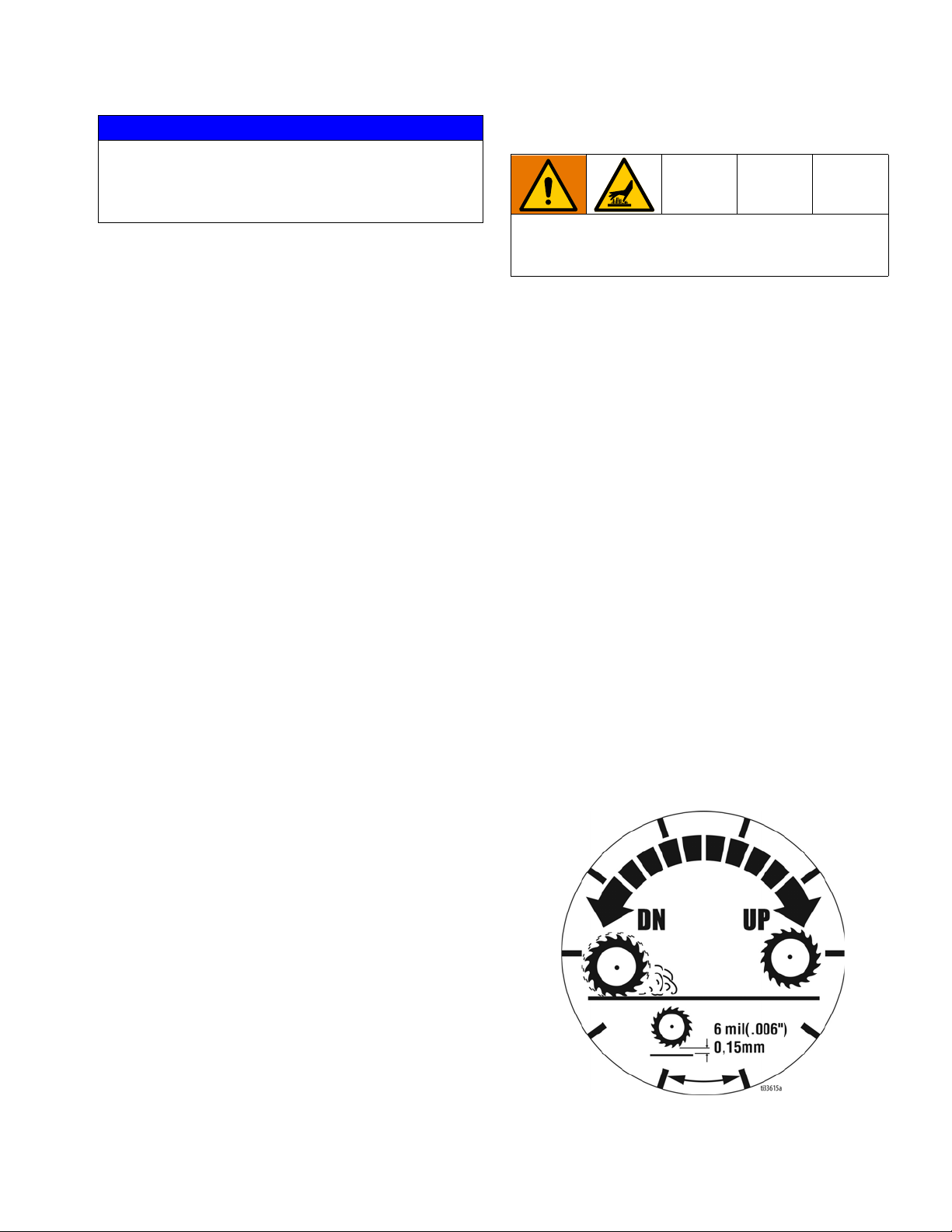
NOTE: Each increment on Drum Adjustment Dial (D) is
0.006 in. (0.15 mm) depth change of cutting drum.
3A5578C 17
Page 18
Operation
Stop Cutting Material
1. Raise Drum Engage Lever so that the drum is off
the ground.
2. Slide Engine Throttle to low setting.
3. Depress Engine Kill Button and turn Engine Power
Switch to “OFF”.
4. Clean the entire exterior of the machine after it has
cooled. Check for worn or damaged parts and
perform any required DCS Instructions on page
19.
18 3A5578C
Page 19
Operation
DCS Instructions
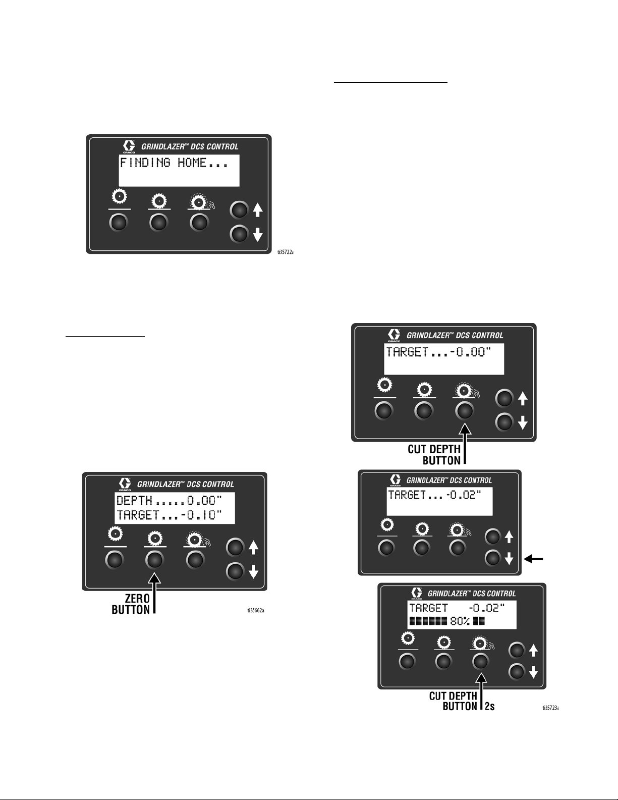
Each time the DCS Control is turned on, the DCS actuator will travel to the Home position.
Once the DCS Control finds Home, ensure the current
model is selected as well as your desired language and
units. See Menu Screens, page 13, for instructions on
changing these settings.
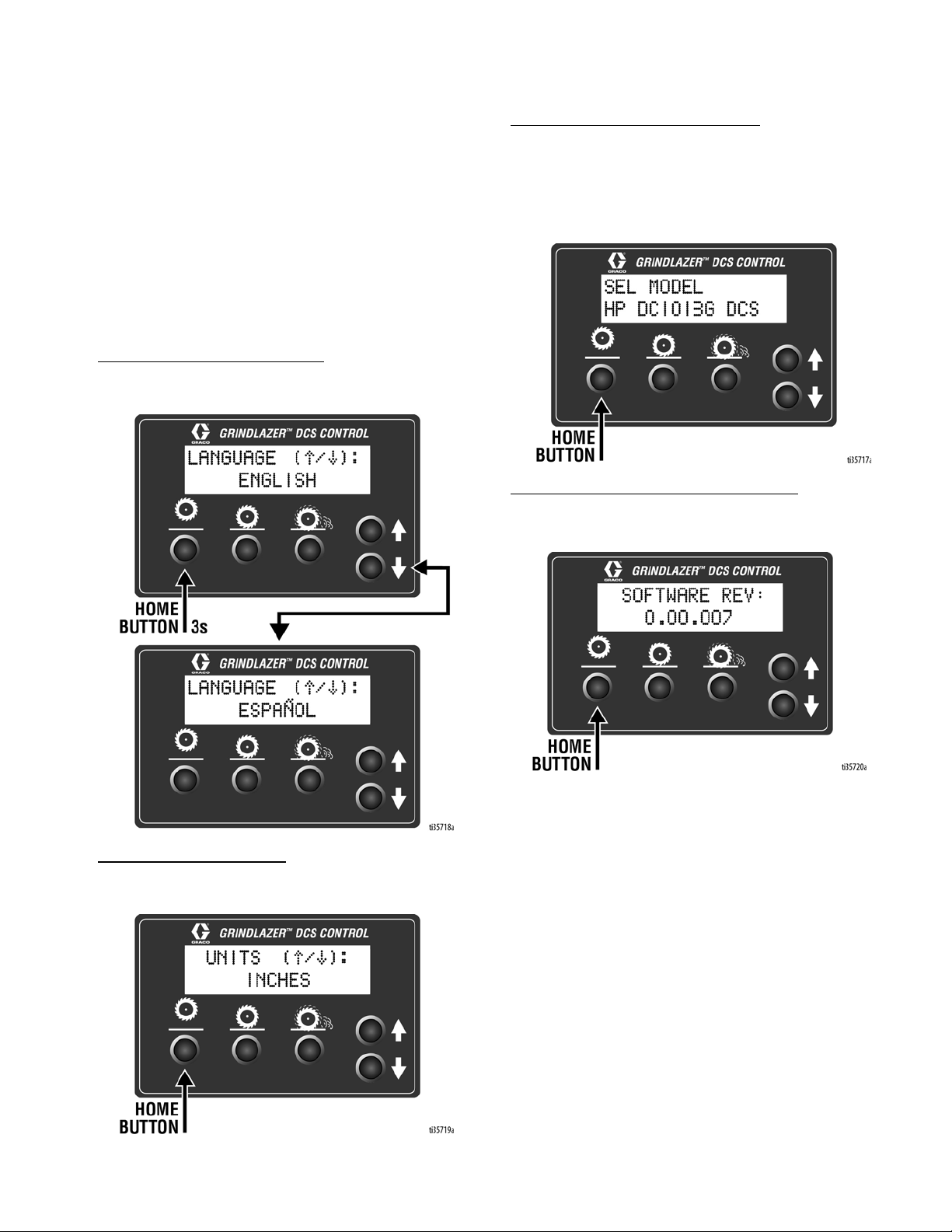
Set Zero Point:
Lower the Depth Control Wheels to the surface by using
the Drum Engage Lever to unlatch the drum housing
from the “up” position. With the engine on, lower the
drum by pressing the Down Arrow Button until you hear
the cutters make contact with the pavement surface.
Hold down the Zero Button for 2 seconds. Your Zero
Point has now been saved.
NOTE: The Cut Depth Target is based off of the Zero
Point. Re-program the Zero Point if the drum is changed
or worn.
Set Cut Depth Target:
Quick press the Zero Button to take the drum to the
pavement surface. Set the Cut Depth Target by:
1. Quick pressing the Down Arrow Button as many
times as needed to achieve your target. Then long
press the Cut Depth Button to save your target.
NOTE: This method will lower the cutting drum into
the pavement surface as you set your cut depth.
OR
2. From the Zero Point, long press the Cut Depth Button until a new screen pops up. Use the Down
Arrow Button to enter your Cut Depth Target. Then
long press the Cut Depth Button to save your target
and return to the Run Screen.
NOTE: This method will keep the cutting drum stationary as you set your Cut Depth Target.
3A5578C 19
Page 20
Operation
The DCS Control is now ready to grind/scarify. Long
press down on the Handlebar Rocker Switch to lower
the drum to your Cut Depth Target. Short press up or
down on the switch to adjust your Cut Depth on the fly.
When finished with your cut, long press up on the switch
to raise the drum to the Home position.
NOTE: The Zero Point and Cut Depth are referenced
from the Home position. Recalibrate your DCS Control
periodically by pressing the Home button or long pressing up on the Handlebar Rocker Switch.
NOTE: Pressing any button while the drum is moving to
Zero or Cut Depth will stop the command and halt the
drum from moving any further up or down until another
button is pressed.
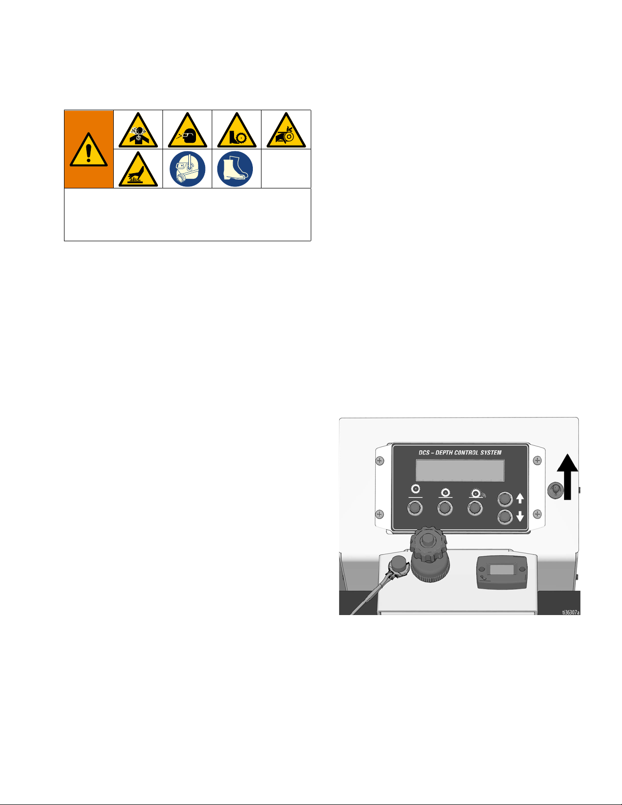
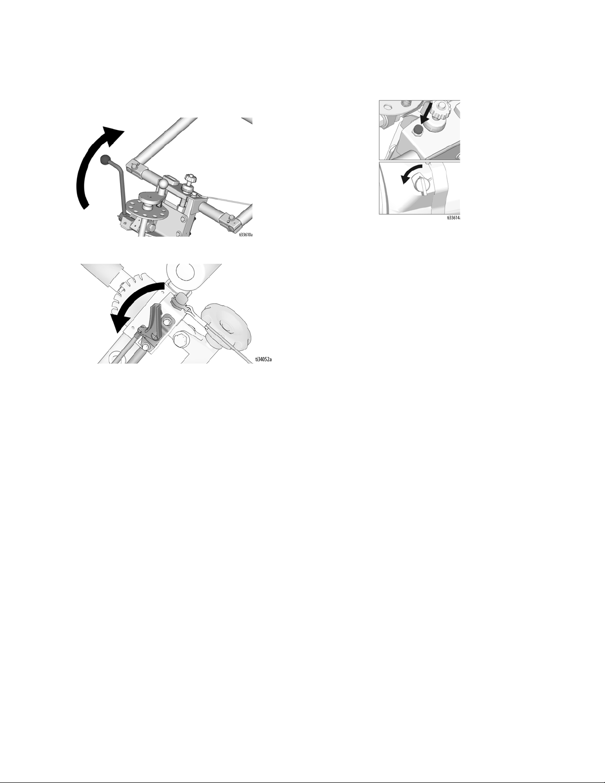
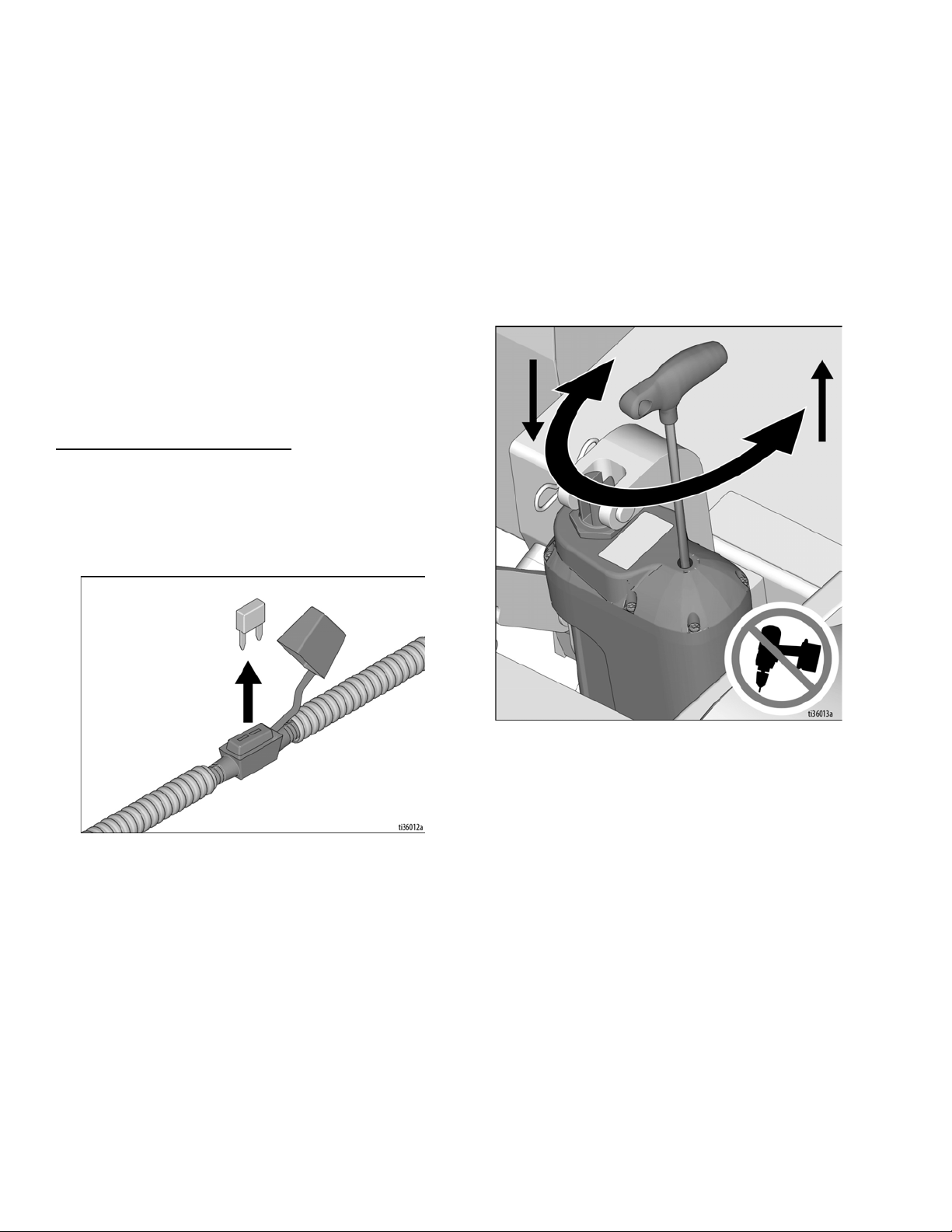
Manual Height Adjustment
If the DCS Control is not usable (dead battery, etc.), the
drum height can be adjusted using the Manual Height
Adjustment feature.
1. Remove fuse from fuse holder near positive battery
terminal. This will protect the battery from damage.
3. Insert 6mm hex key into the port the screw plug was
removed from.
- One revolution of the hex key results in 1/8”
(3mm, 125 mil) of adjustment at the cutter drum.
- Rotate counterclockwise to lower the drum;
rotate clockwise to raise the drum. Max rota-
tion speed of 1 revolution per second. Do
not use power tools in the Manual Height
Adjustment port.
4. Once the desired depth is achieved, replace the
screw plug in order to keep water and dust out.
2. Use a 6mm hex key to remove the screw plug on
the top of the linear actuator.
20 3A5578C
Page 21

Maintenance
Avoid touching engine and drum after use until they
have completely cooled. To avoid unexpected start
up, disconnect spark plug wire before you service
your unit.
The following steps should be performed to maintain
proper operation and sustain the life of the GrindLazer.
BEFORE OPERATION:
• Visually inspect the entire unit for damage or loose
connections.
• Check engine oil (see engine manual).
Maintenance
AFTER THE FIRST 20 HOURS OF
OPERATION:
• Drain engine oil and refill with clean oil. See engine
manual for correct viscosity.
EVERY 40-50 HOURS OF OPERATION:
• Change engine oil (see engine manual).
• Grease wheel bearings.
• Inspect and change drum bushings and shafts.
AS REQUIRED:
• Check drive belt and tension and tighten or replace
as needed.
• Check drum bushings and cutters.
• Check drum for uneven wear.
DAILY:
• Check all fasteners and re-tighten.
• Clean dust and debris from exterior of unit (do NOT
use pressure washer or other high pressure
cleaning equipment).
• Inspect dust skirts for damage. Repair or replace
damaged skirts in order to help dust and debris
containment.
• Check engine oil level and fill as necessary.
• Check and fill gas tank.
• Remove air filter cover and clean element. Replace
element if necessary. Replacement elements can
be purchased from your local engine dealer.
Pro Models:
• Grease the cam lever and lower linkage.
For additional information about engine maintenance,
see engine manual.
3A5578C 21
Page 22

DCS Control Translations
DCS Control Translations
English Español Français Deutsche International
FINDING HOME ENCONTRANDO INICIO
HOME INICIO
DEPTH ALTURA
TARGET OBJETIVO
ZERO CERO
TROUVER LE DÉBUT
DÉBUT
HAUTEUR
OBJECTIF
ZÉRO
START FINDEN
START
TIEFE
ZIEL
NULL
SEL MODEL MODELO
LANGUAGE IDIOMA
UNITS UNIDAD DE MEDIDA
INCHES PULGADAS
MILLIMETERS MILIMETROS
MILS MILS
SOFTWARE REV SOFTWARE REV
ERROR ERROR
MODELE
LA LANGUE
UNITÉ DE MESURE
POUCES
MILLIMETRES
MILS
REVUE SOFTWARE
ERREUR
MODELL
SPRACHE
MAßEINHEIT
ZOLL
MILLIMETER
MILS
SOFTWARE REV
FEHLER
INCH
MM
MIL
22 3A5578C
Page 23

DCS Control Translations
English Español Français Deutsche International
FREQUENCY FRECUENCIA
HIGH CURRENT ALTA CORRIENTE
LOW VOLTAGE BAJO VOLTAJE
HIGH VOLTAGE ALTO VOLTAJE
HALL SENSORS SENSORES DE HALL
HOME BUTTON BOTÓN DE INICIO
FRÉQUENCE
COURANT ÉLEVÉ
BASSE TENSION
HAUTE TENSION
CAPTEURS DE HALL
BOUTON DE DÉBUT
ANZHAL
HOHER STROM
NIEDERSPANNUNG
HOCHSPANNUNG
HALL-SENSOREN
START KNOPF
ZERO BUTTON BOTÓN CERO
CUT BUTTON BOTÓN DE CORTAR
UP BUTTON BOTÓN ARRIBA
DOWN BUTTON BOTÓN DE ABAJO
BOUTON ZÉRO
BOUTON DE COUPE
BOUTON HAUT
BOUTON BAS
NULLTASTE
SCHNITT TASTE
NACH OBEN TASTE
NACH UNTEN TASTE
3A5578C 23
Page 24

Repair
Repair
Drum Replacement for GrindLazer Standard Series Models
Normal use will require periodic drum inspection and
may necessitate drum replacement. Time of
replacement will vary according to usage and load
factors.
Tools needed:
1. 17mm socket or wrench.
2. Rubber mallet.
To avoid injury from unexpected start up, disconnect
spark plug wire before you service your unit.
1. Raise the Drum Engage Lever to the up position so
the cutter drum is off the ground.
4. Slide out drum assembly (use caution as it is
heavy).
5. Once the cutter drum is removed, take to a
workbench for assembly.
a. Inspect condition of cutters, spacers, shafts,
bushings and drum.
6. Before replacing the drum onto hex shaft:
a. Check that all bearings are in good working
order.
2. Remove the three hex head cap screws from the
Drum Access Panel using the 17mm socket or
wrench.
3. Remove Drum Access Panel (this may require the
rubber mallet to break it loose).
b. Remove dirt and material build-up from inside
drive carriage and drum.
c. Lube all metal contacts.
7. Align and slide drum back onto the hex shaft.
8. Replace Drum Access Panel (lift up and lock into
place) over hex shaft and secure hardware.
NOTE: An extra drum loaded with cutters for rapid job
site replacement is recommended.
Drum Replacement for GrindLazer Pro Series Models
Normal use will require periodic drum inspection and
may necessitate drum replacement. Time of
replacement will vary according to usage and load
factors. Tools needed:
1. 9/16” socket or wrench.
2. Rubber mallet.
24 3A5578C
Page 25

c. Lube all metal contacts.
7. Align and slide drum back onto the hex shaft.
Repair
To avoid injury from unexpected start up, disconnect
spark plug wire before you service your unit.
1. Raise the Drum Engage Lever to the up position so
the cutter drum is off the ground.
2. Remove the four hex head cap screws from the
Drum Access Panel using the 9/16” socket or
wrench.
3. Remove the Drum Access Panel (this may require
the rubber mallet to break it loose).
8. Replace Drum Access Panel (lift up and lock into
place) over hex shaft and secure hardware.
NOTE: An extra drum loaded with cutters for rapid job
site replacement is recommended.
Belt Replacement (Standard Models)
Normal wear may necessitate belt tensioning or
replacement. Time of replacement will vary according to
usage and belt load factors.
Replacement is easy and requires a few hand tools.
1. 17mm wrenches.
2. 1/2” socket or wrench.
3. 13mm socket or wrench.
4. Rubber mallet.
4. Slide out drum assembly (use caution as it is
heavy).
5. Once the cutter drum is removed take to a
workbench for assembly.
a. Inspect condition of cutters, spacers, shafts,
bushings and drum.
6. Before replacing the drum onto hex shaft:
a. Check that all bearings are in good working
order.
To avoid injury from unexpected start up, disconnect
spark plug wire before you service your unit.
1. Make sure the Drum Access Panel is installed. This
ensures the drive ends are in the proper position for
servicing.
2. Clean the machine exterior so you can locate all the
appropriate parts.
3. Using a 17mm socket or wrench, remove the two
hex bolts attaching the belt cover to the side of the
machine. Remove the cover and set it aside.
b. Remove dirt and material build-up from inside
3A5578C 25
drive carriage and drum.
Page 26

Repair
4. Using the 1/2” socket or wrench, loosen (do not
remove) the four nylock nuts locking down the
engine until the engine slides freely.
5. Slide the engine back enough to remove and
replace the belts as necessary.
6. Roll the new belt on one groove at a time on both
the top and bottom pulleys.
7. Using the straight edge, lay it across the lower
pulley outer face and against the upper pulley. They
must be directly over top of each other to ensure
long belt life. If adjustment is required, align before
tensioning the belt.
NOTE: It may be necessary to remove the belt guard
support bracket in order to get the straight edge flush on
the pulleys. Do this using a 13mm socket or wrench.
8. Verify pulleys are properly aligned, tighten
everything down and re-check pulley alignment one
last time.
26 3A5578C
Page 27

Repair
Belt Replacement (Pro Models)
Normal wear may necessitate belt tensioning or
replacement. Time of replacement will vary according to
usage and belt load factors.
Replacement is easy and requires a few hand tools.
1. Two 9/16” wrenches.
2. 3/4” wrench.
3. 3/8” open-end wrench.
4. Carpenters square or straight edge.
5. Spray lubricant.
6. Spark plug wrench.
To avoid injury from unexpected start up, disconnect
spark plug wire before you service your unit.
5. Use a 9/16” wrench to loosen the jackscrew
retaining nut.
6. Using the 3/8” open-end wrench, begin to screw the
motor plate jackscrew back into the long hex nut
below it. Screw it all the way until resistance is felt.
7. Loosen (do not remove) the four bolts (2 per side)
that secure the motor mount plate to the main
machine frame.
1. Make sure the Drum Access Panel is installed. This
ensures the drive ends are in the proper position for
servicing.
2. Clean the machine exteriors so you can locate all
the appropriate parts.
3. Using a 3/4” wrench, remove the two acorn nuts
attaching the belt cover to the side of the machine.
Remove the cover and set it aside.
8. Loosen the four bolts attaching the motor to the
motor plate. After sufficiently loosening all four, slide
the motor back all the way to the rear. This will
loosen the belt sufficiently to remove it.
9. Either cut or roll off the belt from the pulleys. If you
roll it off, move it over one groove at a time on the
upper and lower pulleys to completely remove it.
10. Roll the new belt on one groove at a time on both
the top and bottom pulleys.
4. Lubricate the motor plate (belt tensioning) jackscrew
3A5578C 27
with spray lubricant on the front of the machine.
Page 28

Repair
11. Using the straight edge, lay it across the lower
pulley outer face and against the upper pulley. They
must be directly over top of each other to ensure
long belt life. If adjustment is required, align before
tensioning the belt. Tighten the four bolts that
secure the motor mount plate to the frame.
14. From the front of the machine, observe the motor
plate to machine alignment. Tightening the belts
with the jackscrew tends to cause the right side of
the motor plate to lift higher than the left side. By
pushing down on the right front side you can level
the plate and then tighten the front, right screw to
secure in a level position.
12. After installation, use the 3/8” open-end wrench to
screw out the belt tensioning jackscrew under the
motor plate to tension the belts to your desired
tension. Do not over-tension the belt.
13. After the correct tension is reached, tighten the front
motor plate securing screw on the belt side with the
9/16” box end wrench.
15. Tighten the rear securing bolts with the two 9/16”
wrenches.
16. Tighten the motor plate jackscrew retaining nut with
a 9/16” wrench to prevent it from turning.
28 3A5578C
Page 29

Repair
17. Replace the belt cover using the 3/4” wrench.
Belt Alignment
If the unit has premature belt wear, breakage or pulley
problems, the issue may be incorrect alignment or
excessive belt tensioning. All pulleys must be aligned
directly above each other to ensure belt integrity.
1. Use a long straight edge (carpenters square) to
check alignment during belt tensioning or belt
replacement time.
Bearing Replacement (Standard Models)
Tools required:
1. 16mm socket or wrench
2. 1/2” socket or wrench
3. 9/16” socket or wrench
4. 13mm socket or wrench
5. Flat head screw driver
6. Hammer or rubber mallet
7. 6mm hex key
To avoid injury from unexpected start up, disconnect
spark plug wire before you service your unit.
Follow the instructions to remove the drum and belts
from the machine, see Drum Replacement for
GrindLazer Standard Series Models on page 24.
Leave the Drum Access Panel aside to remove the
bearing housing later.
2. By laying the straight edge against the outer face of
the lower pulley, the square will extend up and rest
against the outer face of the upper (engine) pulley. If
the straight edge does not rest against the entire
face of the engine pulley, move the engine pulley in
or out to obtain alignment.
3. If replacing pulleys (top or bottom) be sure to place
the pulley on the same plane as the original one to
ensure alignment.
1. Use a screwdriver to flatten out the tabs that secure
the lock nut to the lower pulley.
2. Remove the lock nut on the shaft by putting the
screw driver on one of the tabs and hitting it with a
hammer or mallet. Remove pulley from shaft.
NOTE: The lock nut has left hand threads, therefore it
must be rotated clockwise to loosen it.
3A5578C 29
Page 30

Repair
3. Once the pulley is removed, the bearing assembly
on that side can be removed using the 6mm hex
key.
4. Remove the bearing housing from the Drum Access
Panel using the 13mm socket or wrench.
Bearing Replacement (Pro Models)
Tools required:
1. 7/16” socket or wrench
2. 1/2” socket or wrench
3. 1” open-end wrench
4. 3/16” Hex Key
5. 5/32” Hex Key
6. 1/8” Hex Key
To avoid injury from unexpected start up, disconnect
spark plug wire before you service your unit.
1. Tip the machine over towards the FRONT and place
the 1” wrench over the hex shaft to prevent it from
rotating.
5. Insert new drive bearing assembly into the drum
housing and tighten the bolts. Insert the drive shaft
key into the key slot. Tighten lock nut onto shaft.
6. Assemble the lower pulley onto the shaft.
7. Slide cutter drum onto shaft.
8. Install new door bearing onto the Drum Access
Panel with the 4 bolts. Assemble the Drum Access
Panel onto the unit.
9. Replace belt and belt guard (see page 25).
30 3A5578C
2. Remove the center screw using the 1/2” socket.
Page 31

Repair
3. Pulley removal:
a. Remove the remaining 3 screws using the 7/16”
socket and insert them by hand into the
threaded holes as shown below (3B).
b. Once all 3 screws are in, begin to turn them
using a socket and do so EVENLY to allow the
bushing to back out smoothly. Once the bushing
is out, remove the pulley and key.
4. Slide the shaft out by removing the 2 set screws
locking it in place using the 3/16” hex key.
5. Remove the bearing assemblies on both sides on
the machine using the 9/16” socket.
6. Install new bearing assemblies onto both sides of
machine. Tighten bolts.
7. Slide the shaft all the way into the drive bearing (so
that it is fully inserted into the Drum Access Panel
Bearing) and lock into place using the 2 set screws
(with thread locker).
8. Insert the drive shaft key into the key slot.
9. Assemble lower pulley onto the shaft.
10. Insert all 4 bolts the into lower pulley and tighten.
11. Replace belt and belt guard (see page 27).
3A5578C 31
Page 32

Repair
Diamond (High Speed) Kit Installation (Pro Models Only)
2. Set the engine pulley aside, and move the lower
pulley to the engine’s shaft (the bushing required is
part of the high speed kit).
To avoid injury from unexpected start up, disconnect
spark plug wire before you service your unit.
The high speed kit is used with the diamond drum
assembly only.
1. Remove belt guard, belt, and both pulleys from the
flail (low speed) setup machine.
3. Place the new pulley and other bushing (included in
the kit) onto the drive shaft.
4. Before tightening the pulleys in place with the
bushings, put the new belt (included in the kit) into
place over the pulleys.
5. Align the pulleys using a straight edge, and tighten
them into place with the bushings. Use thread locker
on all pulley set screws.
6. Replace belt guard.
32 3A5578C
Page 33

Troubleshooting
To avoid injury from unexpected start up, disconnect
spark plug wire before you service your unit.
Problem Cause Solution
Drum is too low Raise drum
Cutters wearing
unevenly/prematurely
Cutters shaft breakage
unevenly/prematurely
Drum wearing prematurely
or cracking
Excessive vibration
Machine jumps erratically
Drive belt wearing prematurely
Drum Engagement Lever will
not raise/lower
Drum Adjustment Dial will
not turn
Uneven cutting
Material build-up Clean the cutters
Cutters too tightly loaded Remove some spacers or cutters from shafts
Wrong cutters for application See 17X074 (Surface Profile Chart)
Drum is too low Raise drum
End plates or bushings worn Replace the end plates and/or bushings
Shafts worn Replace the shafts
Wrong cutter set up
Over 40 hours service life Replace shafts and bushings
Drum hitting ground Raise drum
Shafts and bushings not replaced within 40
hours
Bearing worn Replace worn bearing
Hex bushing worn Replace hex bushing
Drive shaft worn Replace drive shaft
Improper cutter setup
Drum contacting ground Raise drum
Wheels worn out Replace wheels
Drum hitting ground Raise drum
RPM is too low Increase engine RPM
Surface is severely uneven Move to smoother surface
Pulley is misaligned Align pulleys/belt. See page 29.
Wrong belt Replace with correct belt
Drum is contacting the surface Raise drum
Drum Adjustment Dial is set too high or low. Raise or lower Drum Adjustment Dial
Threads are dirty or not greased. Clean and grease the threads
Linkage may be bent Replace linkage
Cutting too deeply Raise drum
Rear wheel fork is bent Replace rear wheel fork
Troubleshooting
Visit
www.graco.com/drumassembly for
proper setup
Replace shafts and bushings
Visit
www.graco.com/drumassembly for
proper setup
3A5578C 33
Page 34

Troubleshooting
DCS Models only
Problem Cause Solution
DCS Control not turning onBlown fuse on DCS Power wire. Replace fuse on DCS Power wire.
Power Switch is OFF or damaged. Turn Power Switch ON. Replace Power
Switch if damged.
Battery is dead. Charge Battery.
DCS Control Board is damaged. Replace DCS Control Board.
DCS Control runs for
short time, then turns off
Engine is not charging the battery. Battery voltage is
14.0-15.0 VDC when engine is full throttle and
charging correctly.
Check engine charging coil, voltage rectifier/regulator and fuse inside engine ignition
box (25N668 only). Replace or repair if
needed.
DCS Control is on, but
actutator and/or drum
housing does not move
DCS display does not
match Cut Depth.
DCS Control Buttons
work, but display is
blank
Actuator is disconnected from DCS Control. Check all connections.
A DCS Control Switch is pressed or defective. Ensure all switches are not stuck. Replace
switches if defective.
Actuator rod is stuck. Manually move the actuator rod using the
Manual Height Adjustment feature. Remove
screw plug on top of the actuator, then use
6mm hex key to move the rod.
Actuator or DCS Control Board is damaged. See flow chart, page 37.
Battery is low. Charge battery.
DCS Control needs to recalibrate its position. Restart the DCS Control.
Zero Position is not set to the pavemet surface. Reprogram the Zero Position. See DCS
Instructions, page 19.
The wrong GrindLazer model is selected on the DCS
Control.
The display is unplugged or damaged. Check that the display ribbon cable and
Select the correct model on DCS Control.
See Menu Screens, page 13.
red/white wire are connected inside Control
Box. Replace if damaged.
34 3A5578C
Page 35

DCS Error Codes
To clear an error code on the DCS Control: 1. Turn DCS Power Switch to OFF.
2. Address/Fix the issue.
3. Turn DCS Power Switch to ON.
Error Cause Solution
Troubleshooting
E04: High Voltage (20VDC or
greater, measured across
battery posts)
E05: High Motor Current (15
Amps or greater, measured
on blue or brown actuator
wire)
E08: Low Voltage (7VDC or
lower, measured across battery posts)
E09: Hall Sensor Error Actuator Signal Cable is disconnected from DCS Control or is
E12: High Current (short circuit, 60 amps or greater,
measured on red or black
wire between battery and
DCS Control)
E31: Home Button Error The Home Button is stuck or shorted. Check to see if Home Button is stuck. If not stuck,
E32: Zero Button Error The Zero Button is stuck or shorted. Check to see if Zero Button is stuck. If not stuck,
E33: Cut Depth Button Error The Cut Depth Button Error is stuck or shorted. Check to see if Cut Depth Button is stuck. If not
Battery is damaged. Replace battery.
Engine voltage rectifier/regulator is damaged. Replace engine voltage rectifier/regulator.
Actuator rod is stuck. Manually move the actuator rod using the Manual
Height Adjustment feature.
Too high of load. Adjust the drum height while the drum is above the
pavement surface. This can be done by latching the
drum housing to the rear frame by pushing down on
the handlebars.
Battery is low/dead. Charge battery.
Engine is not charging the battery. Charge the engine charging coil and voltage recti-
fier/regulator. Replace or repair if needed.
Check all connections. Repair or replace if needed.
damaged.
Actuator or DCS Control Board is damaged. See flow chart, page 37.
A wire or board component has shorted. Check all wires for shorts. If all wires are okay, the
DCS Control board may be damaged and need to be
replaced.
replace the Home Button switch.
replace the Zero Button switch.
stuck, replace the Cut Depth Button switch.
3A5578C 35
Page 36

Troubleshooting
Error Cause Solution
E34: Up Button Error The Up Button or Handlebar Rocker Switch is stuck or shorted. Disconnect Handlebar Rocker Switch from the DCS
E35: Down Button Error The Down Button or Handlebar Switch is stuck or shorted. Disconnect Handlebar Rocker Switch from the DCS
Control. Clear the error code.
If the error code reappears 30 seconds after turning the Power Switch back ON, the problem is the
Up Button on the DCS Control. Check to see if the
Up Button is stuck. If not stuck, replace the Up
Button Switch.
If the error code does not reappear 30 seconds
after turning the Power Switch back ON, the problem is the Handlebar Rocker Switch. Check to see
if the switch is stuck. If not stuck, replace the Handlebar Rocker Switch.
Control. Clear the error code.
If the error code reappears 30 seconds after turning the Power Switch back ON, the problem is the
Down Button on the DCS Control. Check to see if
the Down Button is stuck. If not stuck, replace the
Down Button Switch.
If the error code does not reappear 30 seconds
after turning the Power Switch back ON, the problem is the Handlebar Rocker Switch. Check to see
if the switch is stuck. If not stuck, replace the Handlebar Rocker Switch.
36 3A5578C
Page 37

DCS Actuator Rod Does Not Move
YES NO
Turn power switch to OFF. Remove the blue shroud behind the DCS Control.
Ensure you have a good 12V battery installed. Disconnect the actuator motor
wires and signal cable from the DCS Control. Connect a multimeter between
the blue and brown wires on the DCS Control. Turn the power switch to ON.
Measure the voltage (DC) within 10 seconds of turning the power on. Does it
measure at least 3.0 VDC?
Connect the blue and brown wires on the
actuator to a good 12VDC battery. First try with
the blue wire on positive post and brown wire
on negative post. If the actuator rod does not
move, put the blue wire on the negative post
and the brown wire on the positive post. Does
the rod move in either case?
REPLACE
ACTUATOR
REPLACE
ACTUATOR
REPLACE DCS
CONTROL BOARD
REPLACE DCS
CONTROL BOARD
NO
NO
NO
YES
Within 10 seconds of turning the power switch to ON (while connected to
a good battery), measure the voltage (DC) between the red and black
wires on the actuator signal cable coming from the DCS Control. Does it
measure at least 10 VDC?
Reconnect the actuator motor wires and signal cable from the actuator to
the DCS Control. Turn the power switch to ON. Does the DCS Control
display the Run Screen within 5 seconds?
YES
YES
BLUE
BROWN
12V
Use this flow chart if the DCS Actuator Rod does not
move or if the DCS displays error code E09 (Hall Sensor
Error). Reference Wiring Diagram, page 63.
Troubleshooting
ti36057a
3A5578C 37
Page 38

Parts
*Use industry standard torques when not specified.
Ref. Torque
50-60 in-lb (5.6-6.8 N•m)
40-40 in-lb (4.5-5.0 N•m)
200-225 in-lb (22.5-25.5 N•m)
123
2
1
3
Parts
Drive Assembly (25M842)
38 3A5578C
Page 39

Drive Assembly Parts List (25M842)
Item: P/N Description Qty
1 17W099 5/16-18 Nut 4
2 17W087 5/16” Flat Washer 4
3 17W288 6.5 HP Engine 1
4 17W291 5/16-18x1.5” Carriage Bolt 4
5 17W292 M5-1.0x12mm Set Screw 2
6 17W994 Engine Pulley 1
7 17W038 3/16” Key 1
8 17W995 Woodruff Key 1
9 17W996 Lower Pulley 1
10 17W997 Drive Belt 3
11 17W061 5/16” 1.25” OD Fender Washer 1
12 17W128 5/16” Lock Washer 1
13 17W124 5/16-24x1” Hex Cap Screw 1
14 17W998 Tabbed Washer 1
15 17W999 Slotted Lock Nut 1
16 17X002 Belt Guard 1
17 17X003 M10 30mm OD Fender Washer 2
18 17X004 M10 Lock Washer 2
19 17X005 M10-1.5x16mm Hex Cap Screw 2
20
194126 Warning Label, Fire and Explosion 1
Replacement warning, safety labels, tags, and cards are available at no cost.
Parts
3A5578C 39
Page 40

Parts
*Use industry standard torques when not specified.
Ref. Torque
50-60 in-lb (5.6-6.8 N•m)
40-40 in-lb (4.5-5.0 N•m)
200-225 in-lb (22.5-25.5 N•m)
123
2
1
3
Drive Assembly (25M843)
40 3A5578C
Page 41

Drive Assembly Parts List (25M843)
Item: P/N Description Qty
1 17W095 3/8-16 Nut 4
2 17W008 3/8” Flat Washer 4
3 17W137 9 HP Engine 1
4 17W307 Engine Spacer 2
5 17W308 3/8-16x2” Carriage Bolt 4
6 17W292 M6-1.0x12mm Set Screw 2
7 17W306 Engine Pulley 1
8 17W088 1/4” Key 1
9 17W995 Woodruff Key 1
10 17W996 Lower Pulley 1
11 17W304 Drive Belt 3
12 17W146 7/16” 1.25” OD Fender Washer 1
13 17W159 7/16” Lock Washer 1
14 17W145 7/16-20x1” Hex Cap Screw 1
15 17W998 Tabbed Washer 1
16 17W999 Slotted Lock Nut 1
17 17W305 Belt Guard 1
18 17X003 M10 30mm OD Fender Washer 2
19 17X004 M10 Lock Washer 2
20 17X005 M10-1.5x16mm Hex Cap Screw 2
21
194126 Warning Label, Fire and Explosion 1
Replacement warning, safety labels, tags, and cards are available at no cost.
Parts
3A5578C 41
Page 42

Parts
*Use industry standard torques when not specified.
Ref. Torque
100-110 in-lb (11.3-12.4 N•m)
1
1
Guide Bar Assembly (25M842 and 25M843)
42 3A5578C
Page 43

Guide Bar Assembly (25M842 and 25M843) Parts List
Item: P/N Description Qty
1 17X006 Handlebar Assembly 1
2 17X007 Guide Bar 1
3 17X008 Wheel Carrier 1
4 17X009 Height Adjustment Rod 1
5 17X010 Lower Height Adjustment Clevis 1
6 17X011 Upper Height Adjustment Clevis 1
7 17X012 Height Adjustment Lever Assembly 1
8 17X013 M8-1.25x20mm Hex Cap Screw 2
9 17X014 M8 Lock Washer 2
10 17X003 M10-30mm OD Fender Washer 3
11 17X015 Rear Wheel Assembly 2
12 17X016 Rear Wheel Spacer 2
13 17X017 M10-1.5x40mm Hex Cap Screw 4
14 17X018 M10-1.5x30mm Hex Cap Screw 2
15 17X019 M10-1.5x25mm Hex Cap Screw 3
16 17X004 M10 Lock Washer 3
17 17W425 M10 Flat Washer 11
18 17W424 M10-1.5 Nylon Nut 6
19 17X020 Lower Clevis Spring Pin 2
20 17X021 Brass Bushing 2
21 17X022 Height Adjustment Hand Knob 1
22 17X023 M10-1.5x10mm Set Screw 1
23 17X024 Vacuum Port Cap 1
24 17X025 5/8” ID Rubber Grommet 3
25 17X026 Height Adjustment Lever Spring 1
26 17X027 Height Adjustment Locator Pin 1
27 17W934 M6 Lock Washer 1
28 17X028 M6-1.0 Hex Nut 1
29 17W144 Throttle Cable 1
30 17X029 M5-0.8x10mm Hex Cap Screw 4
31 17X030 M5 Lock Washer 4
32 17X031 M5 Flat Washer 4
33 17X032 Kill Switch Assembly 1
34 17X033 M8 Flat Washer 1
35 17W301 M8-1.25 Nylon Nut 1
36 17X034 Foam Grip 2
37 17X035 7/8” ID Plastic Tube Cap 2
38
17W298 Warning Label, Multiple 1
39 16C394 Warning Label, Entanglement 2
Replacement warning, safety labels, tags, and cards are available at no cost.
Parts
3A5578C 43
Page 44

Parts
*Use industry standard torques when not specified.
Ref. Torque
28-30 ft-lb (38-40 N•m)
1
1
1
1
Primary Housing Assembly (25M842 and 25M843)
44 3A5578C
Page 45

Primary Housing Assembly (25M842 and 25M843) Parts List
Item: P/N Description Qty
1 17X036 Front Caster Wheel Assembly 1
2 17X019 M10-1.5x2.5mm Hex Cap Screw 8
3 17W425 M10 Flat Washer 11
4 17W424 M10-1.5 Nylon Nut 4
5 17X037 Dust Flap Retention Bar 1
6 17X038 Dust Flap 1
7 17X004 M10 Lock Washer 8
8 17X040 Belt Guard Bracket 1
9 17X033 M8 Flat Washer 2
10 17X014 M8 Lock Washer 2
11 17X041 M8-1.25x25mm Hex Cap Screw 2
17X002 Belt Guard (model 25M842) 1
12
17W305 Belt Guard (model 25M843) 1
13 17X005 M10-1.5x16mm Hex Cap Screw 2
14 17X042 Main Housing 1
15 17X044 Side Plate 1
16 17X003 M10-30mm OD Fender Washer 5
17 17X046 M10-1.5 Nylon Nut 1
18 17W886 M6-1.0 Nylon Nut 1
19 17X047 M6 Flat Washer 1
20 17X049 M6-1.0x20mm Hex Cap Screw 1
21 17X018 M10-1.5x30mm Hex Cap Screw 2
22 17X050 Belt Guard Bracket Assembly 1
23
16C393 Warning Label, Foot Cut 1
24 16D646 Warning Label, Hot Surface 1
Replacement warning, safety labels, tags, and cards are available at no cost.
Parts
3A5578C 45
Page 46

Parts
*Use industry standard torques when not specified.
Drum Housing Assembly (25M842 and 25M843)
Drum Housing Assembly (25M842 and 25M843) Parts List
Item: P/N Description Qty
1 17X042 Main Housing 1
2 17X044 Side Plate 1
3 17X060 Drive Side Bearing Assembly 1
4 17X061 Side Plate Bearing Assembly 1
5 17X062 Side Plate Bearing Cover 1
6 17W996 Lower (Drive) Pulley 1
7 17X063 Hex Bushing 1
8 17X064 Hex Bushing C-Clip 1
9 17X065 Shaft Spacer 1
10 17X066 Pulley Spacer 1
11 17W998 Tabbed Washer 1
12 17W999 Slotted Left-Handed Lock Nut 1
13 17X067 M8-1.25x10mm Low Profile Socket
Cap Screw
14 17X068 M8 Belleville Washer 4
15 17X019 M10-1.5x25mm Hex Cap Screw 3
16 17X004 M10 Lock Washer 3
17 17X003 M10-30mm OD Fender Washer 3
46 3A5578C
18 17X069 M8-1.25x18mm Hex Cap Screw 4
19 17X014 M8 Lock Washer 4
20 17X033 M8 Flat Washer 4
21 17X070 Hex Drive Shaft 1
22 17W995 Woodruff Key 1
23 17X071 Side Plate Bearing Assembly 1
4
Page 47

Bearing and Shaft Assembly (25M846, 25N667 & 25N668)
*Use industry standard torques when not specified.
Ref. Torque
30-32 ft-lb (40-43 N•m)
1
1
1
Parts
Bearing and Shaft Assembly (25M846, 25N667 & 25N668) Parts List
Item: P/N Description Qty
1 17W026 Main frame 1
2 17W039 Drive shaft 1
3 17W038 Shaft key 1
4 17W046 Drive side bearing assembly 1
4* 17W953 Drive side bearing assembly 1
5 17W040 Side plate bearing assembly 1
5* 17W954 Side plate bearing assembly 1
6 17W007 3/8” Lock Washer 8
7 17W103 3/8-24x1.25” Hex Cap Screw 4
8 17W083 3/8-24x1.5” Hex Cap Screw 4
9
16C393 Warning label, Foot Cut 2
10
16D646 Warning label, Hot Surface 1
Replacement warning, safety labels, tags, and cards are available at no cost.
* For a machine set up for high speed (diamond) applications.
3A5578C 47
Page 48

Parts
*Use industry standard torques when not specified.
Ref. Torque
24-26 ft-lb (32.5-35.3 N•m)
180-200 in-lb (20.3-22.6 N•m)
70-75 in-lb (7.9-8.5 N•m)
160-170 in-lb (18.1-19.2 N•m)
123
4
2
1
3
4
Rear Assembly (25M846 & 25N667)
48 3A5578C
Page 49

Rear Assembly (25M846 & 25N667) Parts List
Item: P/N Description Qty
1 17W052 3/8-16x1” Hex Cap Screw 4
2 17W007 3/8” Lock Washer 4
3 17W008 3/8” Flat Washer 4
4 17W060 1/2-13x8” Hex Cap Screw 1
5 17W098 1/2” Flat Washer 3
6 17W062 1/2-13 Nylon Nut 1
7 17W057 1/2-20x4” Hex Cap Screw 1
8 17W955 1/2-20 Nylon Jam Nut 1
9 17W058 Wheel Spacer 2
10 17W031 Wheel (rear) 2
11 17W059 Cotter Pin 2
12 17W017 Rear Fork 1
13 17W106 Main Handlebar Frame 1
14 17Y172 Lower Linkage 1
15 17W045 Grease Fitting 2
16 17W056 Locking Collar 1
17 17Y822 Upper Linkage 1
18 17W117 5/8-11x2.5” Hex Cap Screw 1
19 17W114 Belleville Washer 2
20 17W113 Bronze Washer 2
21 17W105 Structural Washer 2
22 17W054 Thrust Bearing 1
23 17Y998 Hand Wheel Assembly 1
24 17W127 E-Clip 1
25 17W111 Spring 1
26 17W119 Locator Pin 1
27 17W049 Ball Knob 2
28 17W108 Cam Lever 1
29 17W285 Handlebar Back Plate 1
30 17W081 5/16-18x2.5” Hex Cap Screw 4
31 17W087 5/16” Flat Washer 8
32 17W099 5/16-18 Nylon Nut 4
33 17W084 #10-32x0.25” Set Screw 1
34 17W121 Damper Assembly 1
35 17W956 Linkage/Hand Wheel Assembly 1
36 17W138 Handle Graco (Model 25N667) 2
Parts
3A5578C 49
Page 50

Parts
*Use industry standard torques when not specified.
Ref. Torque
28-30 ft-lb (38.0-40.7 N•m)
12-15 ft-lb (16.3-20.3 N•m)
7-8 ft-lb (9.5-10.8 N•m)
72-84 in-lb (8.1-9.5 N•m)
144-180 in-lb (16.2-20.0 N•m)
12345
Rear Assembly (25N668)
50 3A5578C
Page 51

Rear Assembly (25N668) Parts List
Item: P/N Description Qty
1 17W052 3/8-16x1” Hex Cap Screw 4
2 17W007 3/8” Lock Washer 4
3 17W008 3/8” Flat Washer 4
4 17W060 1/2-13x8” Hex Cap Screw 1
5 17W098 1/2” Flat Washer 3
6 17W062 1/2-13 Nylon Nut 1
7 17W057 1/2-20x4” Hex Cap Screw 1
8 17W955 1/2-20 Nylon Jam Nut 1
9 17W058 Wheel Spacer 2
10 17W031 Wheel (rear) 2
11 17W059 Cotter Pin 2
12 17W017 Rear Fork 1
13 17Z123 Main Handlebar Frame 1
14 17Z140 Lower Linkage 1
15 10115 Battery Cover 1
16 115753 Selead Battery, 33Ah 1
17 17Z142 Battery Bracket 1
18 25N506 DCS Assembly Control 1
19 17Y237 Actuator, Linear 12V, 3 stroke 1
20 17Z139 Upper Linkage 1
21 18A114 Pin 2
22 17Y962 Cotter Pin, Bow Tie 2
23 16Y269 Flat Washer, M12 4
24 17W124 5/16-18x1.75 Hex Head Cap Screw 1
25 17W087 5/16 Flat Washer 2
26 110838 5/16-18 Nylon Hex Nut 1
27 18A197 DCS Power Switch Harness 1
29 17W285 Handlebar Back Plate 1
30 17W081 5/16-18x2.5” Hex Cap Screw 4
31 17W087 5/16” Flat Washer 8
32 17W099 5/16-18 Nylon Nut 4
36 17W260 10-32x3/4 Cap Screw 4
37 17X178 Flat Washer 4
38 102920 Nut 4
Parts
3A5578C 51
Page 52

Parts
*Use industry standard torques when not specified.
Ref. Torque
150-160 in-lb (16.9-18.1 N•m)
95-105 in-lb (10.7-11.9 N•m)
1
2
2
1
Damper Assembly (25M846, 25N667)
Damper Assembly (25M846 & 25N667) Parts List
Item: P/N Description Qty
1 17W126 Shock Absorber 1
2 17W123 Lower Attachment Link 1
3 17W122 Upper Attachment Link 1
4 17W124 5/16-18x1.75” Hex Cap Screw 1
5 17W087 5/16” Flat Washer 1
6 17W099 5/16-18 Nylon Hex Nut 1
7 17W125 3/8-16x3.5” Hex Cap Screw 1
8 17W095 3/8-16 Nylon Nut 1
9 17W008 3/8” Flat Washer 2
10 17W121 Damper Assembly (incl. items 1-9) 1
52 3A5578C
Page 53

NOTES
Parts
3A5578C 53
Page 54

Parts
Use industry standard torques when not specified.
Ref. Torque
120-140 in-lb (13.6-15.8 N•m)
55-65 in-lb (6.2-7.3 N•m)
22-24 ft-lb (29.8-32.5 N•m)
19-21 ft-lb (25.8-28.5 N•m)
123
4
2
1
3
4
3
3
*
Front Assembly (25M846, 25N667 & 25N668)
54 3A5578C
Page 55

Front Assembly (25M846, 25N667 & 25N668) Parts List
Item: P/N Description Qty
1 17W030 Front Wheel (with bearings) 2
2 17W072 Locking Collar 2
3 17W032 Axle Shaft 1
4* 17W023 1/4-20x1” Hex Cap Screw 9
5* 17W020 1/4” Flat Washer 10
6* 17W021 1/4” Fender Washer 10
7* 17W022 1/4-20 Nylock Nut 10
8 17W019 Brush Strip Assembly (set of 4) 1
9 17W104 1/2-20x1” Hex Cap Screw 2
10 17W064 1/2” Lock Washer 4
11 17W098 1/2” Flat Washer 6
12 17W027 Side Plate 1
13 17W082 3/8-24x0.75” Hex Cap Screw 4
14 17W007 3/8” Lock Washer 4
15 17W008 3/8” Flat Washer 8
16* 17W025 1/4-20x1” Low Profile Screw 1
19* 17Y119 Engine Mount (Model 25N667) 1
17Z141 Engine Mount (Model 25M846 & 25N668) 1
20 17W093 3/8-16x3” Carriage Bolt 1
21 17W094 3/8-16 Hex Nut 1
22 17W097 3/8-16x1” Carriage Bolt 4
23 17W095 3/8-16 Nylon Nut 4
24 17W069 1/2-13x5.5” Hex Cap Screw 2
25 17W075 Cap Plug 2
26 17W068 Spacer 2
27 17W067 1/2-13 Hex Nut 2
28 17W018 Belt Guard 1
29 17W063 1/2-13 Acorn Nut 2
30 17W066 Hole Plug (Belt Guard) 1
31 17W957 Hole Plug (Housing) 1
32
17W115 Warning Label, Multiple 1
33
16C393 Warning Label, Foot Cut 1
16C394 Warning Label, Entanglement 2
34
Replacement warning, safety labels, tags, and cards are available at no cost.
* Items are part of item 8.
Parts
3A5578C 55
Page 56

Parts
*Use industry standard torques when not specified.
Ref. Torque
22-24 ft-lb (29.8-32.5 N•m)
1
1
Handle Bar Assembly (25M846)
Handle Bar Assembly (25M846) Parts List
Item: P/N Description Qty
1 17W281 Long Handle Bar Grip (49” Long) 1
2 17W005 Handle Bar Tubing 1
3 17W002 Short Handle Bar Grip (4” Long) 2
4 17W003 Handle Bar Clamp 4
5 17W006 3/8-16x1.5” Hex Cap Screw 4
6 17W007 3/8” Lock Washer 4
7 17W087 5/16” Flat Washer 4
8 17W009 3/4” Plastic Tube Cap 2
56 3A5578C
Page 57

Handle Bar Assembly (25N668)
*Use industry standard torques when not specified.
Ref. Torque
240-264 in-lb (27.1-30.0 N•m)
72--84 in-lb (8.1-9.5 N•m)
1
2
Parts
Handle Bar Assembly (25N668) Parts List
Item: P/N Description Qty
1 18A350 Handle Bar Tubing 2
2 18A400 Foam Grip, Left 1
3 18A401 Foam Grip, Right 1
4 17W003 Handle Bar Clamp 4
5 17W006 3/8-16x1.5” Hex Cap Screw 4
6 17W007 3/8” Lock Washer 4
7 17W087 5/16” Flat Washer 4
3A5578C 57
8 17W009 3/4” Plastic Tube Cap 2
9 17Y120 Control Switch Housing 1
10 15K780 10-32 x 3/8” Set Screw 1
11 100002 1/4”-20 x 1/4” Set Screw 2
12 17Y999 Rocker Switch 1
13 18A120 Rocker Switch Wire Assembly 1
14 17W002 Foam Grip, small 2
15 17W268 3/16” dia x 1-1/4” Pin, Roll 2
Page 58

Parts
*Use industry standard torques when not specified.
Ref. Torque
160-170 in-lb (18.1-19.2 N•m)
1
1
1
1
Drive Assembly (25M846 & 25N667)
58 3A5578C
Page 59

Drive Assembly (25M846 & 25N667) Parts List
Item: P/N Description Qty
1 17W286 13hp Engine (Model 25M846) 1
123966 9hp Engine (Model 25N667) 1
2 17W080 3/8-16x1.75” Carriage Bolt 4
3 17W008 3/8” Flat Washer 4
4 17W095 3/8-16 Nylock Nut 4
5 17W960 Throttle Cable Assembly 1
6 17W961 Kill Switch Assembly 1
7 17W029 Deflector for Honda Engine 1
8 17W088 Key for Engine Pulley 1
9 17W096 3/8-24x1” Hex Cap Screw 1
10 17W007 3/8” Lock Washer 1
11 17W109 3/8” Fender Washer 1
12 17W074 5/16-24x0.75” Hex Cap Screw 1
13 17W128 5/16” Lock Washer 1
14 17W061 5/16” Fender Washer 1
15 17W038 Key for Drive Pulley 1
16 17W284 Tachometer/Hour Meter 1
17* 17W129 Throttle Cable Mount 1
18* 17W963 Throttle Cable Screw 1
19* 17W130 Throttle Mount C-Clip 1
20* 17W964 Deflector Mounting Screw 3
21
194126 Warning Label, Fire and Explosion 1
Replacement warning, safety labels, tags, and cards are available at no cost.
Parts
Flail (Low Speed) Set Up
Item: P/N Description Qty
A 17W034 Engine Pulley 1
B N/A Engine Pulley Bushing 1
C 17W036 Drive Pulley 1
D 17W037 Drive Pulley Bushing 1
E 17W035 Drive Belt 1
Diamond (High Speed) Set Up
Item: P/N Description Qty
A 17W036 Engine Pulley 1
B 17W965 Engine Pulley Bushing 1
C 17W966 Drive Pulley 1
D 17W967 Drive Pulley Bushing 1
E 17W968 Drive Belt 1
NOTE: Bearing assemblies (P/N 17W953 and 17W954)
are required when the machine is to be used for high
speed diamond blade applications (see Bearing and
Shaft Assembly (25M846, 25N667 & 25N668) on page
47.
3A5578C 59
Page 60

Parts
*Use industry standard torques when not specified.
Ref. Torque
12-15 ft-lb (16.3-20.3 N•m)
2-3 ft-lb (2.7-4.1 N•m)
1
2
Drive Assembly (25N668)
60 3A5578C
Page 61

Drive Assembly (25N668) Parts List
Item: P/N Description Qty
1 17Y714 13hp Engine (Model 25N668) 1
2 17W080 3/8-16x1.75” Carriage Bolt 4
3 17W008 3/8” Flat Washer 4
4 17W095 3/8-16 Nylock Nut 4
5 17W960 Throttle Cable Assembly 1
6 18A198 Kill Switch Assembly 1
7 17W034 Engine Pulley 1
8 17W088 Key for Engine Pulley 1
9 17W096 3/8-24x1” Hex Cap Screw 1
10 17W007 3/8” Lock Washer 1
11 17W109 3/8” Fender Washer 1
12 17W074 5/16-24x0.75” Hex Cap Screw 1
13 17W128 5/16” Lock Washer 1
14 17W061 5/16” Fender Washer 1
15 17W038 Key for Drive Pulley 1
16 17W284 Tachometer/Hour Meter 1
17 17W129 Throttle Cable Mount 1
18 17W963 Throttle Cable Screw 1
19 17W130 Throttle Mount C-Clip 1
20 17W036 Drive Pulley 1
21 17W037 Drive Pulley Bushing 1
22 17W035 Drive Belt 1
23 18A788 Battery Cover 1
24 117501 Screw, Mach, Slot Hex Wash Head 3
25 17X233 1/4-20 x 1-1/4 Bolt, Hex Head 2
26 17W020 1/4 Washer Flat 4
27 17W022 1/4-20 Nylock Nut 2
28 555352 10-24 x 3/8” Set Screw 1
Parts
3A5578C 61
Page 62

DCS Control Box 18A790
DCS Control Box 18A790
25N668 only
Parts List
Ref. Part Description Qty.
300 18A690 KIT, DCS Control Box, machined
includes 300a - 300f
301 17Y686 LABEL, control, GrindLazer DCS
302 18A691 KIT, potted DCS Control PCB
303 18A692 KIT, display board, DCS control
62 3A5578C
Ref. Part Description Qty.
304 18A693 KIT, home button, DCS
1
305 18A694 KIT, zero button, DCS
1
306 18A695 KIT, cut cutton, DCS
1
307 18A696 KIT, up button, DCS
1
308 18A697 KIT, down button, DCS
1
1
1
1
1
Page 63

Wiring Diagram
17Y999
17Y237
DCS System
Wiring Diagram
3A5578C 63
Page 64

Wiring Diagram
Powers Display
DCS Control Box
64 3A5578C
Page 65

Technical Data
GrindLazer Standard DC87 G (25M842)
Noise level (dBa)
Sound power
Sound pressure
Vibration level*
Right/Left Hand
* Vibration measured per ISO 5349 based on 8 hr daily exposure
Dimensions/Weight (unpackaged) US Metric
Height 40 in. 102 cm
Length 42 in. 107 cm
Width 15 in. 38 cm
Weight 125 lb 57 kg
GrindLazer Standard DC89 G (25M843)
Noise level (dBa)
Sound power
Sound pressure
Vibration level*
Right/Left Hand
* Vibration measured per ISO 5349 based on 8 hr daily exposure
Dimensions/Weight (unpackaged) US Metric
Height 40 in. 102 cm
Length 42 in. 107 cm
Width 16 in. 41 cm
Weight 150 lb 68 kg
107 dBa per ISO 3744
92 dBa measured at 3.1 feet (1m)
11.4 m/sec
107 dBa per ISO 3744
92 dBa measured at 3.1 feet (1m)
9.5 m/sec
2
2
Technical Data
GrindLazer Pro DC1013 G (25M846)
Noise level (dBa)
Sound power
Sound pressure
Vibration level*
Right/Left Hand
* Vibration measured per ISO 5349 based on 8 hr daily exposure
Dimensions/Weight (unpackaged) US Metric
Height (handle up) 53 in. 135 cm
Height (handle down) 42 in. 107 cm
Length 38 in. 97 cm
Width 20 in. 51 cm
Weight 250 lb 114 kg
3A5578C 65
109 dBa per ISO 3744
94 dBa measured at 3.1 feet (1m)
13.5 m/sec
2
Page 66

Technical Data
WARNING: This product can expose you to chemicals known to the State of California to cause cancer
and birth defects or other reproductive harm. For more information go to www.P65Warnings.ca.gov.
CALIFORNIA PROPOSITION 65
GrindLazer Pro DC89 G (25N667)
Noise level (dBa)
Sound power
Sound pressure
109 dBa per ISO 3744
94 dBa measured at 3.1 feet (1m)
Vibration level*
Right/Left Hand
13.5 m/sec
2
* Vibration measured per ISO 5349 based on 8 hr daily exposure
Dimensions/Weight (unpackaged) US Metric
Height (handle up) 53 in. 135 cm
Height (handle down) 42 in. 107 cm
Length 38 in. 97 cm
Width 20 in. 51 cm
Weight 192 lb 87 kg
GrindLazer Pro DC1013 DCS (25N668)
Noise level (dBa)
Sound power
Sound pressure
109 dBa per ISO 3744
94 dBa measured at 3.1 feet (1m)
Vibration level*
Right/Left Hand
13.5 m/sec
2
* Vibration measured per ISO 5349 based on 8 hr daily exposure
Dimensions/Weight (unpackaged) US Metric
Height (handle up) 53 in. 135 cm
Height (handle down) 42 in. 107 cm
Length 38 in. 97 cm
Width 20 in. 51 cm
Weight 263 lb 119 kg
66 3A5578C
Page 67

Graco Standard Warranty
Graco Standard Warranty
Graco warrants all equipment referenced in this document which is manufactured by Graco and bearing its name to be free from defects in
material and workmanship on the date of sale to the original purchaser for use. With the exception of any special, extended, or limited warranty
published by Graco, Graco will, for a period of twelve months from the date of sale, repair or replace any part of the equipment determined by
Graco to be defective. This warranty applies only when the equipment is installed, operated and maintained in accordance with Graco’s written
recommendations.
This warranty does not cover, and Graco shall not be liable for general wear and tear, or any malfunction, damage or wear caused by faulty
installation, misapplication, abrasion, corrosion, inadequate or improper maintenance, negligence, accident, tampering, or substitution of
non-Graco component parts. Nor shall Graco be liable for malfunction, damage or wear caused by the incompatibility of Graco equipment with
structures, accessories, equipment or materials not supplied by Graco, or the improper design, manufacture, installation, operation or
maintenance of structures, accessories, equipment or materials not supplied by Graco.
This warranty is conditioned upon the prepaid return of the equipment claimed to be defective to an authorized Graco distributor for verification of
the claimed defect. If the claimed defect is verified, Graco will repair or replace free of charge any defective parts. The equipment will be returned
to the original purchaser transportation prepaid. If inspection of the equipment does not disclose any defect in material or workmanship, repairs
will be made at a reasonable charge, which charges may include the costs of parts, labor, and transportation.
THIS WARRANTY IS EXCLUSIVE, AND IS IN LIEU OF ANY OTHER WARRANTIES, EXPRESS OR IMPLIED, INCLUDING BUT NOT
LIMITED TO WARRANTY OF MERCHANTABILITY OR WARRANTY OF FITNESS FOR A PARTICULAR PURPOSE.
Graco’s sole obligation and buyer’s sole remedy for any breach of warranty shall be as set forth above. The buyer agrees that no other remedy
(including, but not limited to, incidental or consequential damages for lost profits, lost sales, injury to person or property, or any other incidental or
consequential loss) shall be available. Any action for breach of warranty must be brought within two (2) years of the date of sale.
GRACO MAKES NO WARRANTY, AND DISCLAIMS ALL IMPLIED WARRANTIES OF MERCHANTABILITY AND FITNESS FOR A
PARTICULAR PURPOSE, IN CONNECTION WITH ACCESSORIES, EQUIPMENT, MATERIALS OR COMPONENTS SOLD BUT NOT
MANUFACTURED BY GRACO. These items sold, but not manufactured by Graco (such as electric motors, switches, hose, etc.), are subject to
the warranty, if any, of their manufacturer. Graco will provide purchaser with reasonable assistance in making any claim for breach of these
warranties.
In no event will Graco be liable for indirect, incidental, special or consequential damages resulting from Graco supplying equipment hereunder, or
the furnishing, performance, or use of any products or other goods sold hereto, whether due to a breach of contract, breach of warranty, the
negligence of Graco, or otherwise.
FOR GRACO CANADA CUSTOMERS
The Parties acknowledge that they have required that the present document, as well as all documents, notices and legal proceedings entered into,
given or instituted pursuant hereto or relating directly or indirectly hereto, be drawn up in English. Les parties reconnaissent avoir convenu que la
rédaction du présente document sera en Anglais, ainsi que tous documents, avis et procédures judiciaires exécutés, donnés ou intentés, à la suite
de ou en rapport, directement ou indirectement, avec les procédures concernées.
3A5578C 67
Page 68

Graco Information
For the latest information about Graco products, visit www.graco.com.
For patent information, see www.graco.com/patents.
TO PLACE AN ORDER, contact your Graco distributor or call 1-800-690-2894 to identify the nearest distributor.
All written and visual data contained in this document reflects the latest product information available at the time of publication.
GRACO INC. AND SUBSIDIARIES • P.O. BOX 1441 • MINNEAPOLIS MN 55440-1441 • USA
Copyright 2018, Graco Inc. All Graco manufacturing locations are registered to ISO 9001.
Graco reserves the right to make changes at any time without notice.
Original instructions. This manual contains English. MM 3A5578
International Offices: Belgium, China, Japan, Korea
Graco Headquarters: Minneapolis
www.graco.com
Revision
C, April 2019
 Loading...