

Page 1
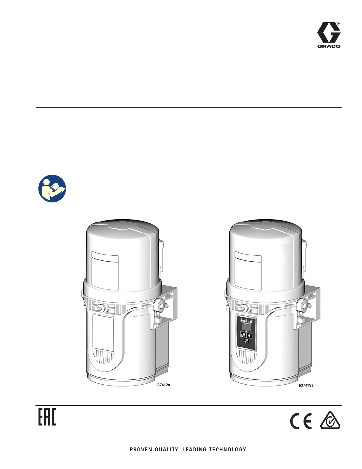
Instructions
™
G-Mini
For dispensing NLGI Grades #000 to #2 greases. For professional use only.
Not approved for use in explosive atmospheres or hazardous (classified) locations.
Models, page 3
4061 psi (28 MPa, 280 bar) Maximum Working Pressure
Important Safety Instructions
Read all warnings and instructions in this
manual before using the equipment.
Save these instructions.
Pump
3A6714C
EN
Page 2

Contents
Contents
Models . . . . . . . . . . . . . . . . . . . . . . . . . . . . . . . . . . . . 3
Warnings . . . . . . . . . . . . . . . . . . . . . . . . . . . . . . . . . . 4
Installation . . . . . . . . . . . . . . . . . . . . . . . . . . . . . . . . . 6
Typical Installation . . . . . . . . . . . . . . . . . . . . . . . . 7
Divider Installation Remote............................. 7
CSP Direct Mount Installation......................... 7
Choose an Installation Location . . . . . . . . . . . . . . 8
Fuses.............................................................. 9
Recommendations for Pump Usage in
Harsh Environments................................. 9
Wiring and Installation Diagrams .................... 9
Manual Run Button . . . . . . . . . . . . . . . . . . . . . . 14
Proximity Switch. . . . . . . . . . . . . . . . . . . . . . . . . 14
Setup . . . . . . . . . . . . . . . . . . . . . . . . . . . . . . . . . . . . 15
Pressure Relief Procedure . . . . . . . . . . . . . . . . . 15
Disconnect and isolate all power supplies.... 15
Connect to Auxiliary Fittings . . . . . . . . . . . . . . . 15
Pressure Relief Valves ................................. 15
Pressure Relief Valves. . . . . . . . . . . . . . . . . . . . 15
Set Pump Outlet Volume . . . . . . . . . . . . . . . . . . 16
Load Grease . . . . . . . . . . . . . . . . . . . . . . . . . . . 16
Change Greases .......................................... 17
Priming. . . . . . . . . . . . . . . . . . . . . . . . . . . . . . . . 18
Non Controller Operation . . . . . . . . . . . . . . . . . . . . . 19
Low-Level Output Option .............................. 19
Controller Operation . . . . . . . . . . . . . . . . . . . . . . . . . 20
RUN MODE . . . . . . . . . . . . . . . . . . . . . . . . . . . . 21
SETUP MODE . . . . . . . . . . . . . . . . . . . . . . . . . . 21
ON TIME Configuration (Minutes) ................ 21
ON TIME Configuration (Cycles) .................. 22
OFF TIME Configuration (Min./Hrs).............. 22
ADVANCED PROGRAMMING . . . . . . . . . . . . . 23
Advanced Programming Menu Descriptions 23
Alerts and Alarms . . . . . . . . . . . . . . . . . . . . . . . . . . . 26
Alerts . . . . . . . . . . . . . . . . . . . . . . . . . . . . . . . . . 26
Alarms . . . . . . . . . . . . . . . . . . . . . . . . . . . . . . . . 26
Alert and Alarm Scenarios . . . . . . . . . . . . . . . . . 27
Troubleshooting . . . . . . . . . . . . . . . . . . . . . . . . . . . . 28
Maintenance . . . . . . . . . . . . . . . . . . . . . . . . . . . . . . . 29
Repair . . . . . . . . . . . . . . . . . . . . . . . . . . . . . . . . . . . . 30
Reservoir Kits . . . . . . . . . . . . . . . . . . . . . . . . . . . 30
Pump Element Kits . . . . . . . . . . . . . . . . . . . . . . . 30
Parts . . . . . . . . . . . . . . . . . . . . . . . . . . . . . . . . . . . . . 31
CSP Valve Bracket Mount . . . . . . . . . . . . . . . . . 31
Dimensions . . . . . . . . . . . . . . . . . . . . . . . . . . . . . . . . 34
Pump Mount . . . . . . . . . . . . . . . . . . . . . . . . . . . . 35
Universal Bracket Mount . . . . . . . . . . . . . . . . . . 35
Technical Specifications . . . . . . . . . . . . . . . . . . . . . . 36
Graco Standard Warranty . . . . . . . . . . . . . . . . . . . . . 38
2 3A6714C
Page 3

Models
Models
Reservoir
Non-
Model
25R800 X X X CPC X 1
25R801 X X X CPC X M12 1
25R802 X X X CPC X 1
25R803 X X X CPC X M12 1
25R804 X X X CPC X M12 1 X
25R805 X X X CPC X M12 2 X
25R806 X X X CPC X M12 1 X
25R807 X X X CPC X 1
25R808 X X X CPC X M12 1
25R809 X X X CPC X 1
25R810 X X X CPC X M12 1
25R820 X X X DIN X 1
25R821 X X X DIN X M12 1
25R822 X X X DIN X 1
25R823 X X X DIN X M12 1
25R824 X X X DIN X M12 1 X
25R825 X X X DIN X M12 2 X
25R826 X X X DIN X M12 1 X
25R827 X X X DIN X 1
25R828 X X X DIN X M12 1
25R829 X X X DIN X 1
25R830 X X X DIN X M12 1
Controller
Controller
Voltage
Power
Input
Low
Level
Cycle
Feedback
Input
Pump
Element
Quantity
Heater0.5 L 1 L 12VDC 24VDC
3A6714C 3
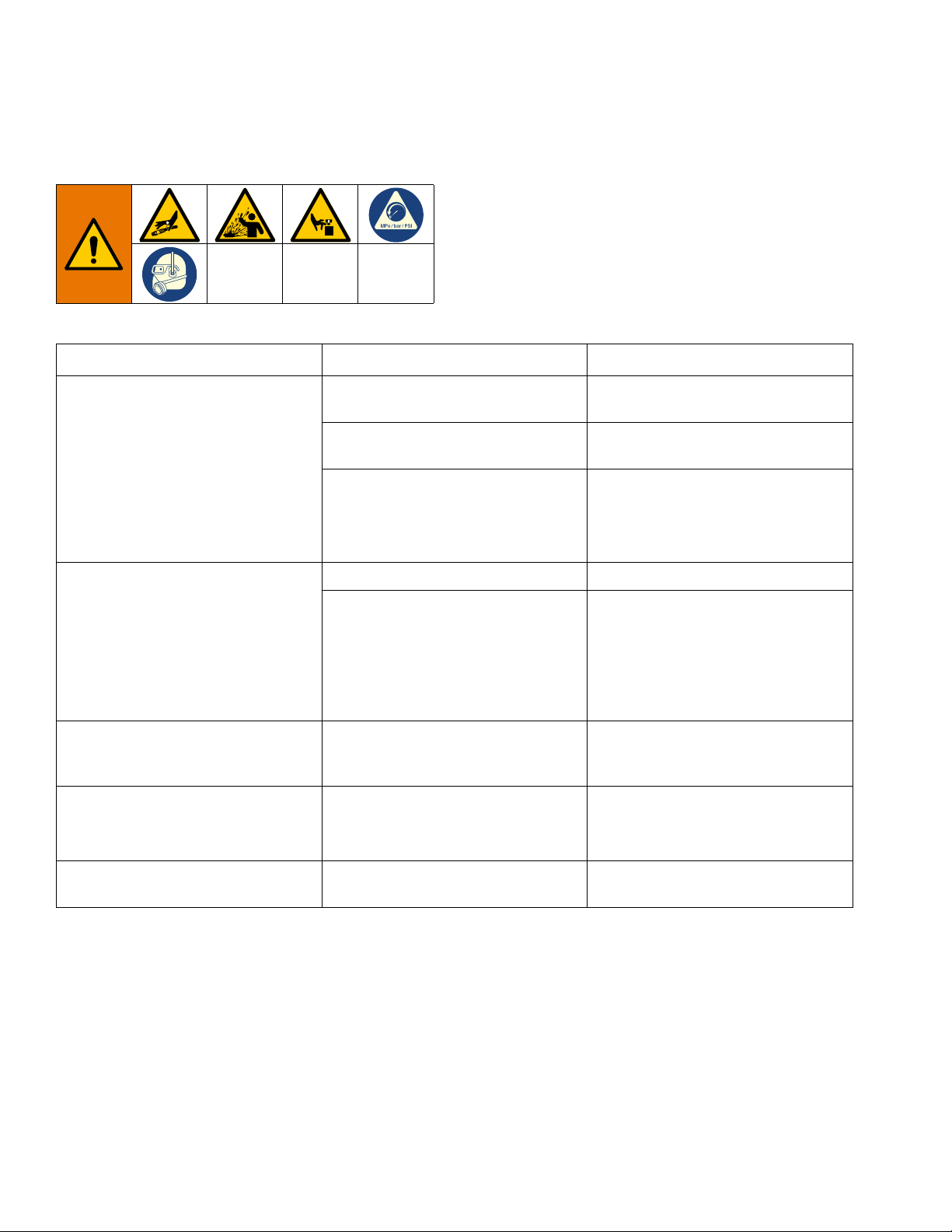
Page 4
Warnings
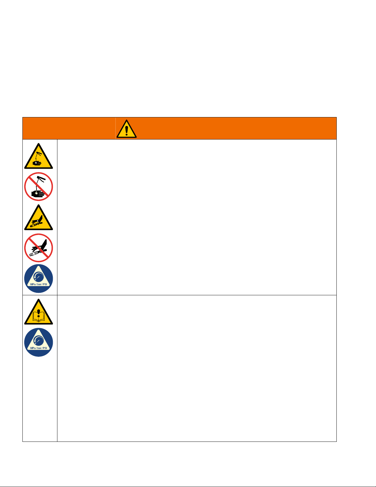
WARNING
Warnings
The following warnings are for the setup, use, maintenance, and repair of this equipment. The exclamation point
symbol alerts you to a general warning and the hazard symbols refer to procedure-specific risks. When these
symbols appear in the body of this manual or on warning labels, refer back to these Warnings. Product-specific
hazard symbols and warnings not covered in this section may appear throughout the body of this manual where
applicable.
SKIN INJECTION HAZARD
High-pressure fluid from dispensing device, hose leaks, or ruptured components will pierce skin. This
may look like just a cut, but it is a serious injury that can result in amputation. Get immediate surgical
treatment.
• Do not point dispensing device at anyone or at any part of the body.
• Do not put your hand over the fluid outlet.
• Do not stop or deflect leaks with your hand, body, glove, or rag.
• Follow the Pressure Relief Procedure when you stop dispensing and before cleaning, checking, or
servicing equipment.
• Tighten all fluid connections before operating the equipment.
• Check hoses and couplings daily. Replace worn or damaged parts immediately.
EQUIPMENT MISUSE HAZARD
Misuse can cause death or serious injury.
• Do not operate the unit when fatigued or under the influence of drugs or alcohol.
• Do not exceed the maximum working pressure or temperature rating of the lowest rated system
component. See Technical Specifications in all equipment manuals.
• Use fluids and solvents that are compatible with equipment wetted parts. See Technical
Specifications in all equipment manuals. Read fluid and solvent manufacturer’s warnings. For
complete information about your material, request Safety Data Sheets (SDSs) from distributor or
retailer.
• Turn off all equipment and follow the Pressure Relief Procedure when equipment is not in use.
• Check equipment daily. Repair or replace worn or damaged parts immediately with genuine
manufacturer’s replacement parts only.
• Do not alter or modify equipment. Alterations or modifications may void agency approvals and create
safety hazards.
• Make sure all equipment is rated and approved for the environment in which you are using it.
• Use equipment only for its intended purpose. Call your distributor for information.
• Route hoses and cables away from traffic areas, sharp edges, moving parts, and hot surfaces.
• Do not kink or over bend hoses or use hoses to pull equipment.
• Keep children and animals away from work area.
• Comply with all applicable safety regulations.
4 3A6714C
Page 5
Warnings
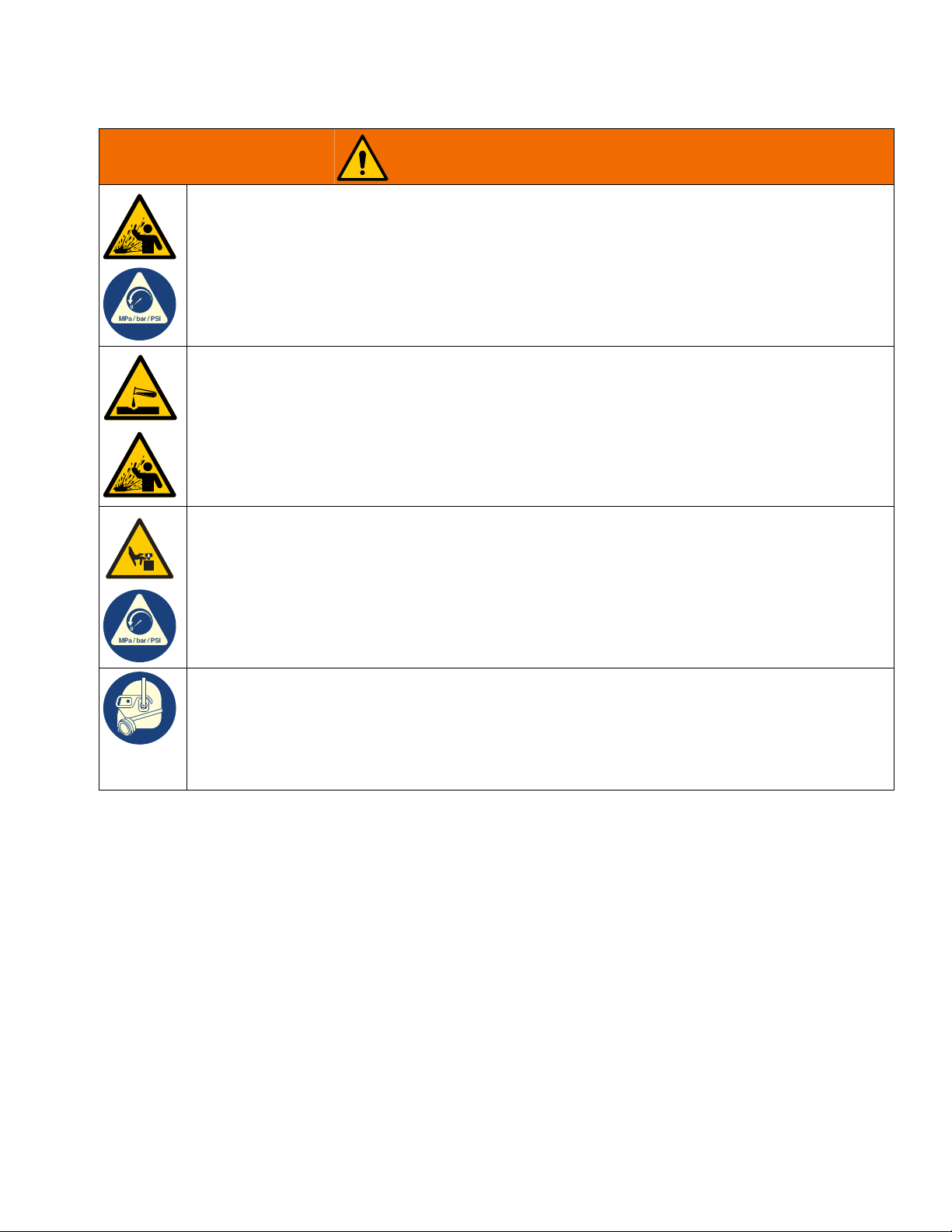
WARNING
PRESSURIZED EQUIPMENT HAZARD
Over-pressurization can result in equipment rupture and serious injury.
• A pressure relief valve is required at each pump outlet.
• Follow the Pressure Relief Procedure in this manual when servicing equipment.
PLASTIC PARTS CLEANING SOLVENT HAZARD
Many cleaning solvents can degrade plastic parts and cause them to fail, which could cause serious
injury or property damage.
• Use only compatible solvents to clean plastic structural or pressure-containing parts.
• See Technical Specifications in all equipment manuals for materials of construction. Consult the
solvent manufacturer for information and recommendations about compatibility.
MOVING PARTS HAZARD
Moving parts can pinch, cut or amputate fingers and other body parts.
• Keep clear of moving parts.
• Do not operate equipment with protective guards or covers removed.
• Equipment can start without warning. Before checking, moving, or servicing equipment, follow the
Pressure Relief Procedure and disconnect all power sources.
PERSONAL PROTECTIVE EQUIPMENT
Wear appropriate protective equipment when in the work area to help prevent serious injury, including
eye injury, hearing loss, inhalation of toxic fumes, and burns. Protective equipment includes but is not
limited to:
• Protective eyewear, and hearing protection.
• Respirators, protective clothing, and gloves as recommended by the fluid and solvent manufacturer.
3A6714C 5
Page 6
Installation
D
A
B
C
F
G
E
H
J
J
V
W
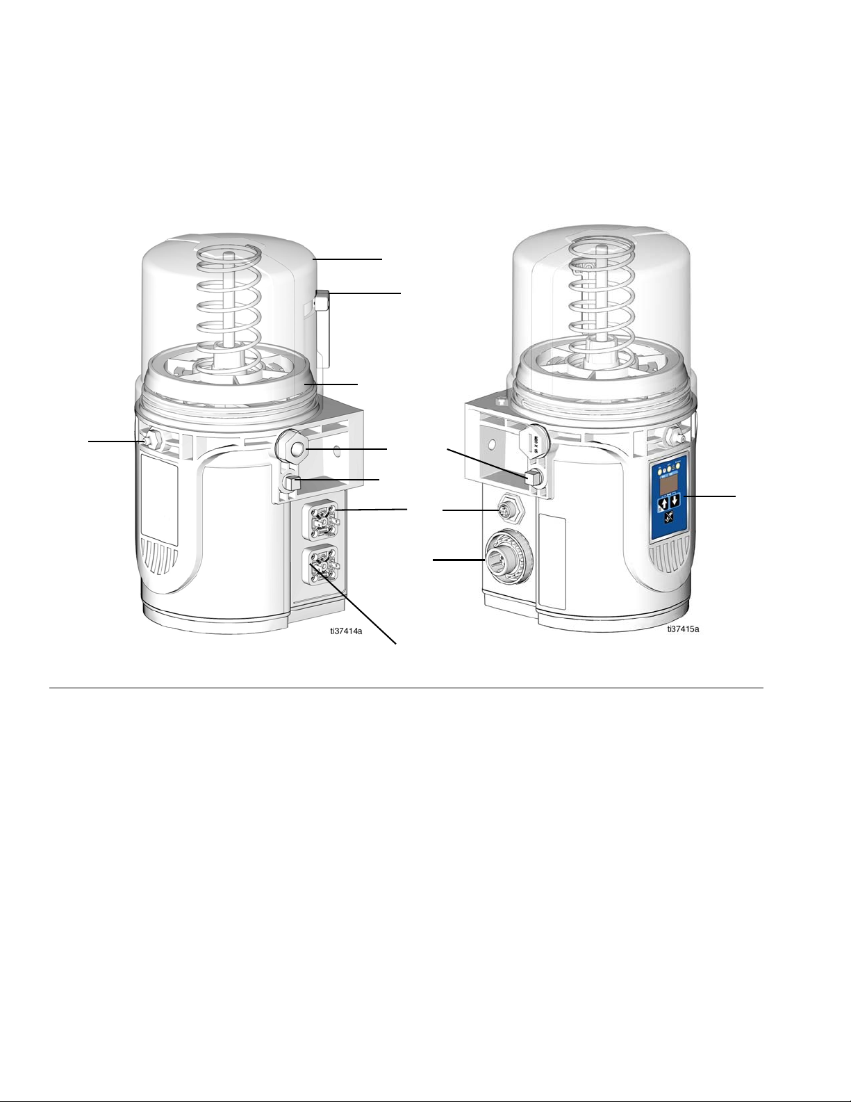
Installation
Component Identification
FIG. 1:
Key:
A Reservoir
B Venting Tube
C Follower Plate
D Pump Element
E Zerk Inlet Fill Fitting
F Cycle Indicator Connector (Controller model only)
G CPC Connector
H Controller
J Return to Reservoir
V DIN Connector (Power)
W DIN Connector (Low level/Manual run button)
6 3A6714C
Page 7
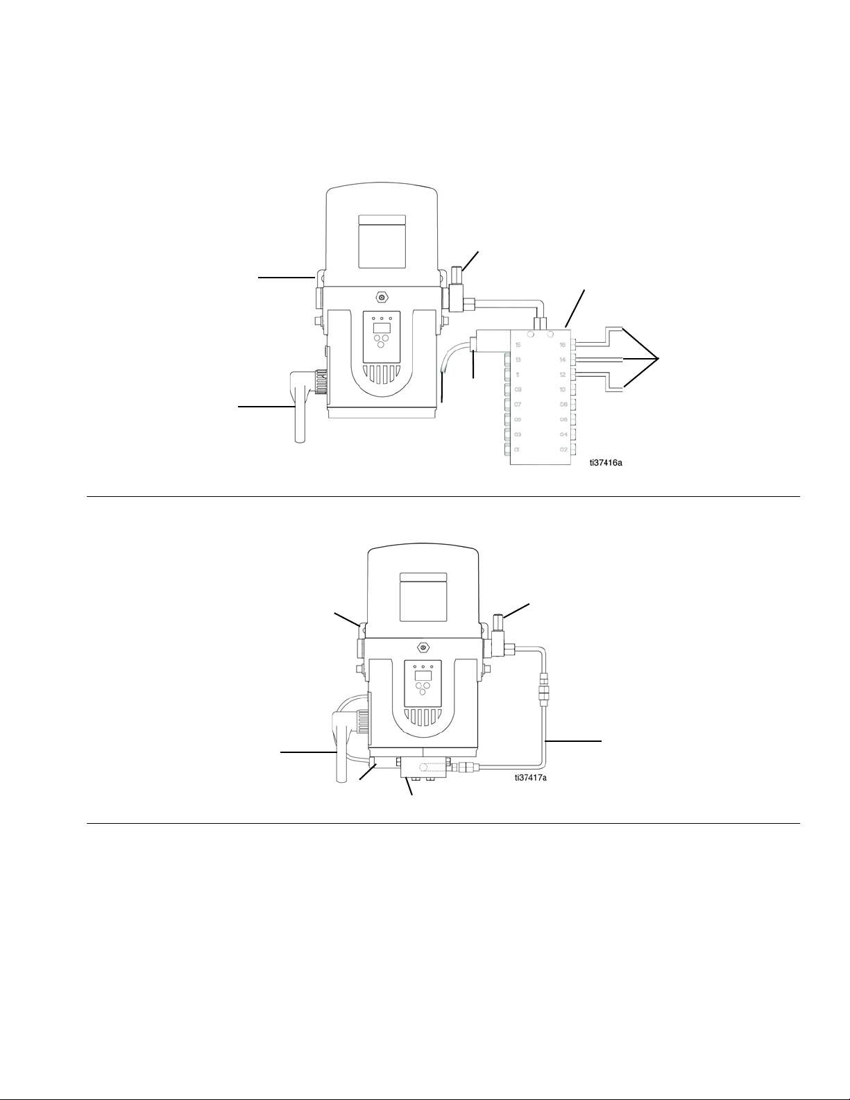
Typical Installation
K
R
P
N
M
L
X
R
S
L
K
T
U
Divider Installation Remote
Installation
FIG. 2:
CSP Direct Mount Installation
FIG. 3:
K Connection to fused power source
L Pressure relief valve (required for each outlet)*
See Pressure Relief Valves, page 15
M Proximity switch cable
N Series progressive divider valves (Divider Installation)
P Connection to lube points
R Proximity switch, see page 14
S Direct Mount CSP Bracket, see page 8
T Direct Mount CSP Hose, see page 8
U CSP valves
X Universal Bracket, see page 8
*User Supplied
3A6714C 7
Page 8
Installation
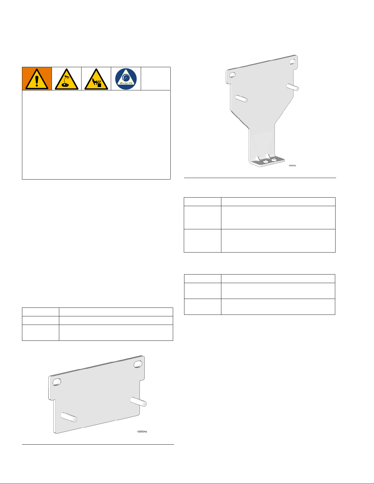
Choose an Installation Location
AUTOMATIC SYSTEM ACTIVATION HAZARD
Unexpected activation of the system could result in
serious injury, including skin injection and amputation.
This device has an automatic timer that activates the
pump lubrication system when power is connected or
when exiting the programming function. Before you
install the lubrication pump or remove it from the system, disconnect and isolate all power supplies and
relieve all pressure.
FIG. 5: 26C825
• Select a location that will support the weight of the
pump and lubricant, as well as all plumbing and
electrical connections.
• Refer to the two mounting hole layouts provided in
the Mounting Pattern section of this manual, page
35.
• Use designated mounting holes and provided configurations only.
• Use the two fasteners (included) to secure the pump
to the mounting surface.
Some installations may require an additional pump
bracket.
Mounting Bracket Kits
Part No Description
26C826 Universal Bracket (fastener included)
26C825
Direct Mount CSP Bracket (fastener
included)
Direct Mount CSP Hose Kits
Part No Description
1/4 NPT (Pressure Relief Outlet) to 1/8
26C956
26C957
Direct CSP Mount Kits
Part No Description
26C958
26C959
NPT (CSP Inlet), includes hose (25 cm
length), fitting 17T781and 17T783
1/4 NPT (Pressure Relief Outlet) to 1/8
BSPT (CSP Inlet), includes hose (25 cm
length), fitting 17L546 and 17T783
Kit, CSP Mount, NPT, includes 26C825
and 26C956
Kit, CSP Mount, BSPT, includes 26C825
and 26C957
F
IG. 4: 26C826
8 3A6714C
Page 9
System Configuration and Wiring
All electrical wiring must be done by a qualified
electrician and comply with all local codes and
regulations.
Installation
Recommendations for Pump Usage in
Harsh Environments
• Use pump with CPC style power cable.
• Use a corrosion preventative electrical grease on all
contacts.
Fuses
NOTICE
Fuses (user supplied) are required on all DC models.
To avoid equipment damage:
• Never operate pump DC models without a fuse
installed.
• A fuse of the correct amperage must be installed in
line with the power entry to the system.
Fuse kits are available from Graco. The following table
identifies the correct fuse to use for the input voltage
and the corresponding Graco Kit number.
Applicable
Fuse Value Graco Kit No.
10A 26C916
5A 26C917
7.5A 571039
Model
25R802
25R803
25R806
25R809
25R810
25R822
25R823
25R826
25R829
25R730
25R800
25R807
25R820
25R827
25R801
25R804
25R805
25R808
25R821
25R824
25R825
25R828
Wiring and Installation Diagrams
NOTE: Wire colors provided on these pages refer only
to the Graco power cable.
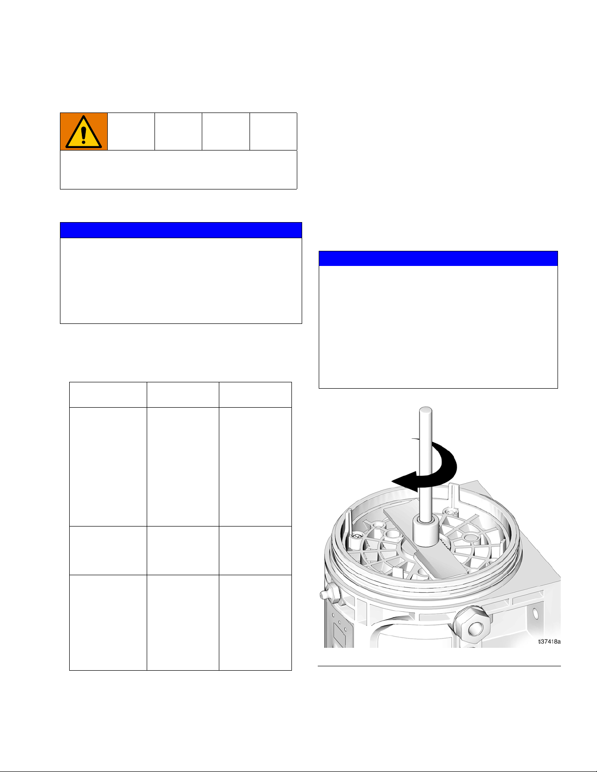
NOTICE
The stirring paddle should rotate clockwise (as viewed
from the top) (F
the stirring paddle to rotate counterclockwise damages the pump’s internal components.
If the stirring paddle is rotating counterclockwise, stop
the pump immediately. Check that the wiring is correct
and make any necessary changes.
If the motor does not run after power is supplied,
check the pump wiring.
FIG. 6
IG. 6) when power is applied. Allowing
3A6714C 9
Page 10
Installation
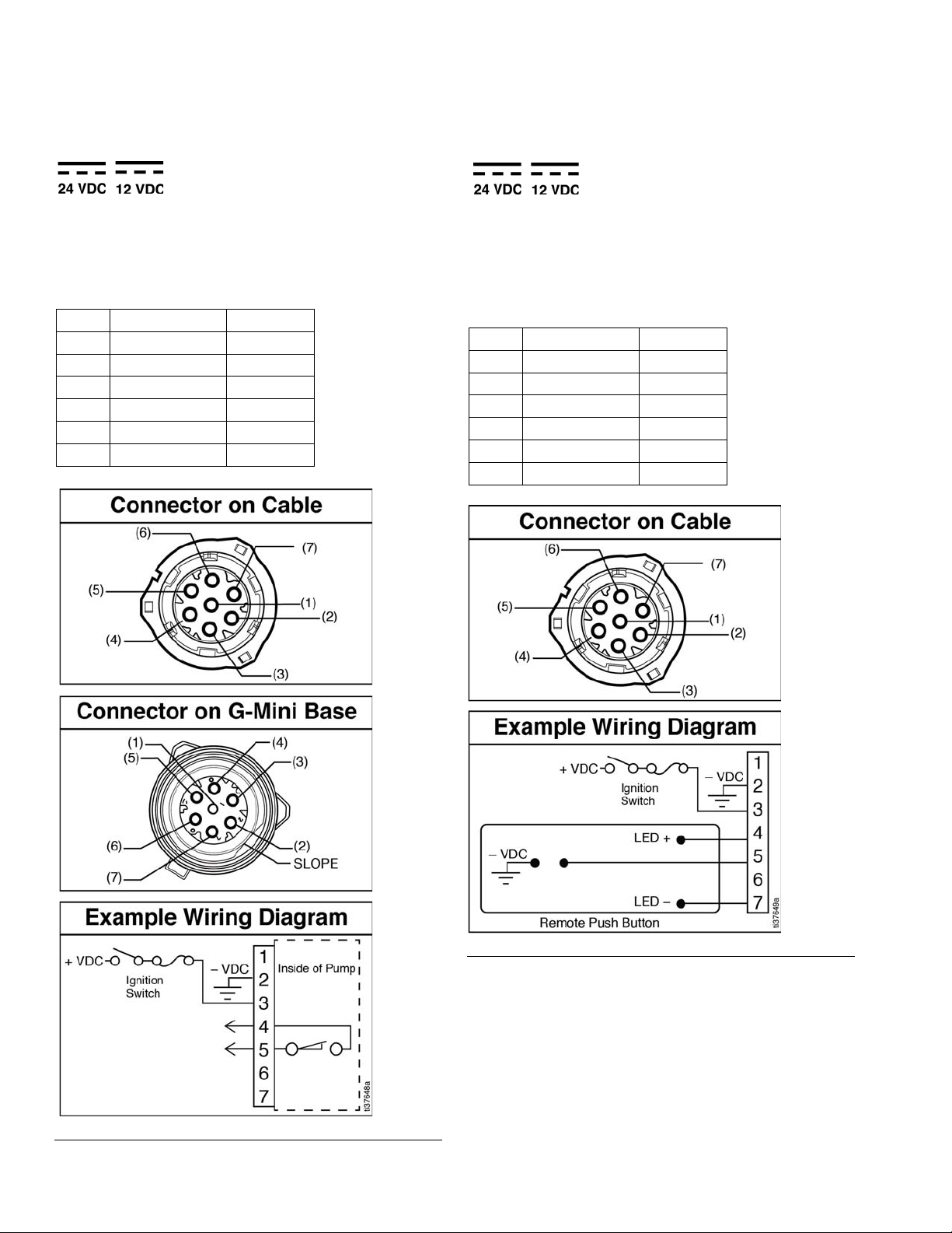
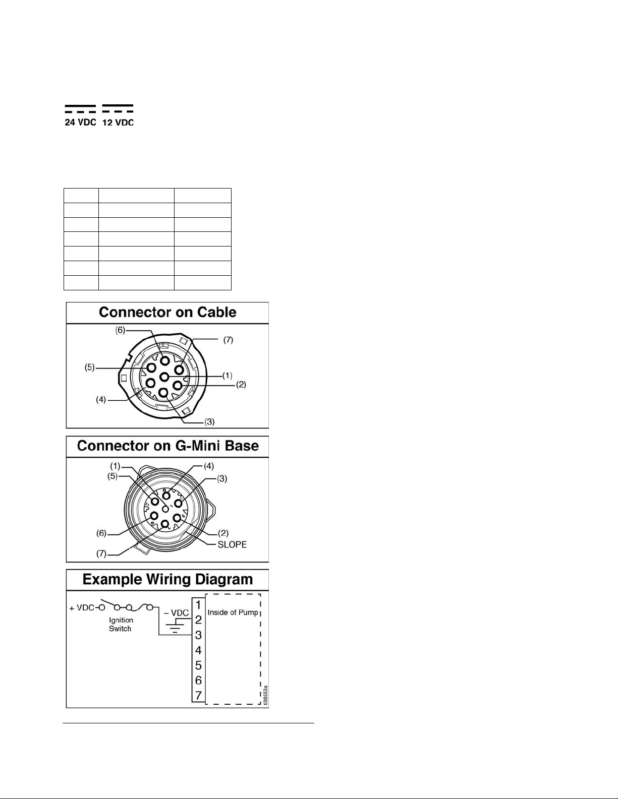
Power CPC DC - 5 Wire (Non-Controller)
Power Cable CPC DC
Part No.: 127780 - 15 ft. (4.5 m), 127781 - 20 ft. (6.1 m),
127782 - 30 ft. (9.1 m)
Pin Out
1 Not Used Not Used
2 -VDC Black
3+VDC Red
4 Low-Level White
5 Low-Level Orange
6 Not Used Not Used
7 Not Used Green
Power CPC DC - 5 Wire (Controller)
Power Cable CPC DC
Part No.: 127780 - 15 ft. (4.5 m), 127781 - 20 ft. (6.1 m),
127782 - 30 ft. (9.1 m)
Pin Out
1 Not Used Not Used
2 -VDC Black
3+VDC Red
4LED+ White
5 Button Orange
6 Not Used Not Used
7LED- Green
FIG. 8
FIG. 7
10 3A6714C
Page 11
Power CPC DC - 3 Wire (Non-Controller)
Power Cable CPC DC
Part No.: 127783 - 15 ft. (4.5 m)
Pin Out
1 Not Used Not Used
2 -VDC Black
3+VDC White
4 Not Used Not Used
5 Not Used Not Used
6 Not Used Not Used
7 Not Used Not Used
Installation
FIG. 9
3A6714C 11
Page 12
Installation
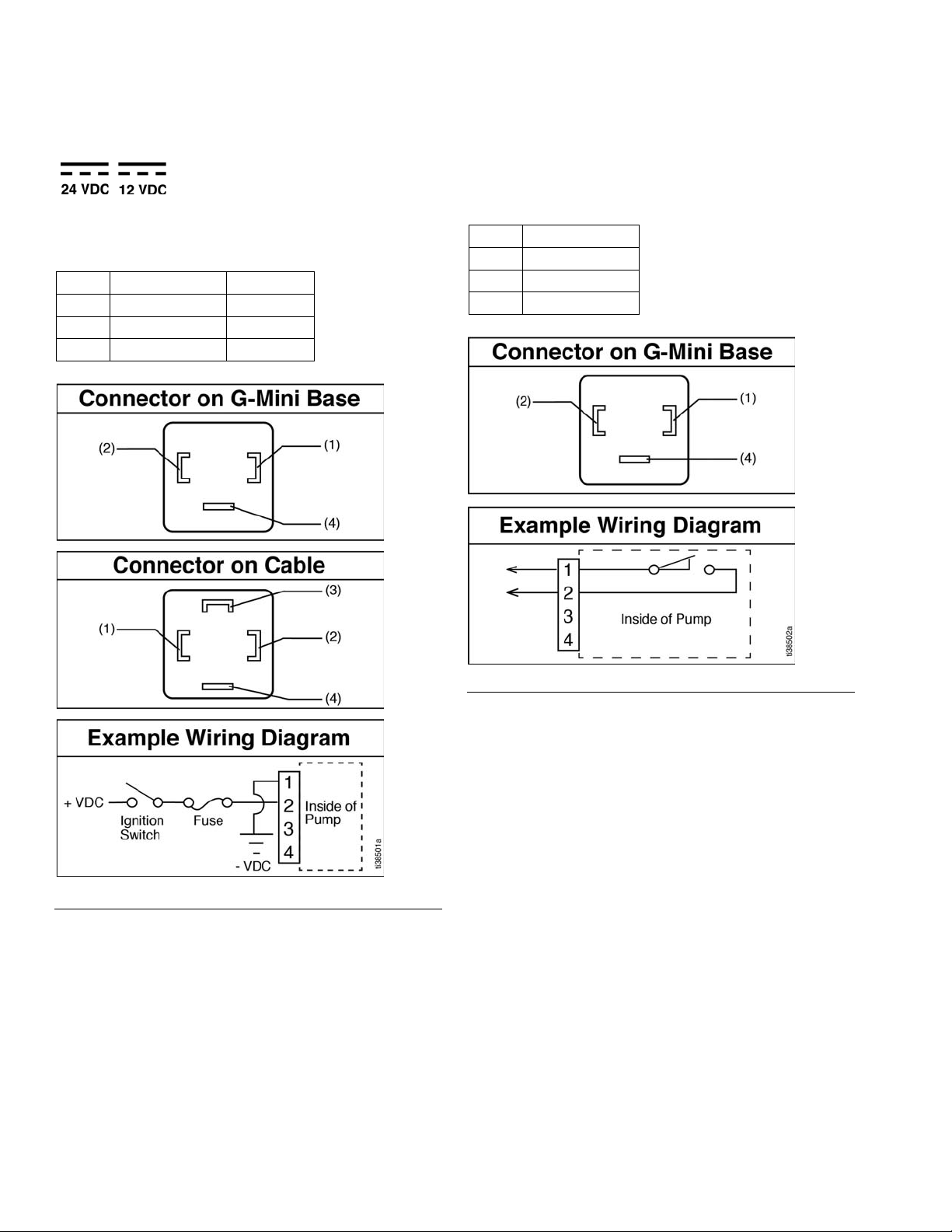
Power DIN DC - 15 ft Power Cable: Part No, 16U790
Pin Out
1 -VDC Black
2+VDC White
3 Not Used Not Used
4 Not Used Green
Low Level DIN DC
See Technical Specifications, page 36 for ratings
Pin Out
1 LL N.O.
2 LL Com
3Not Used
4Not Used
FIG. 10
FIG. 11
12 3A6714C
Page 13
Installation
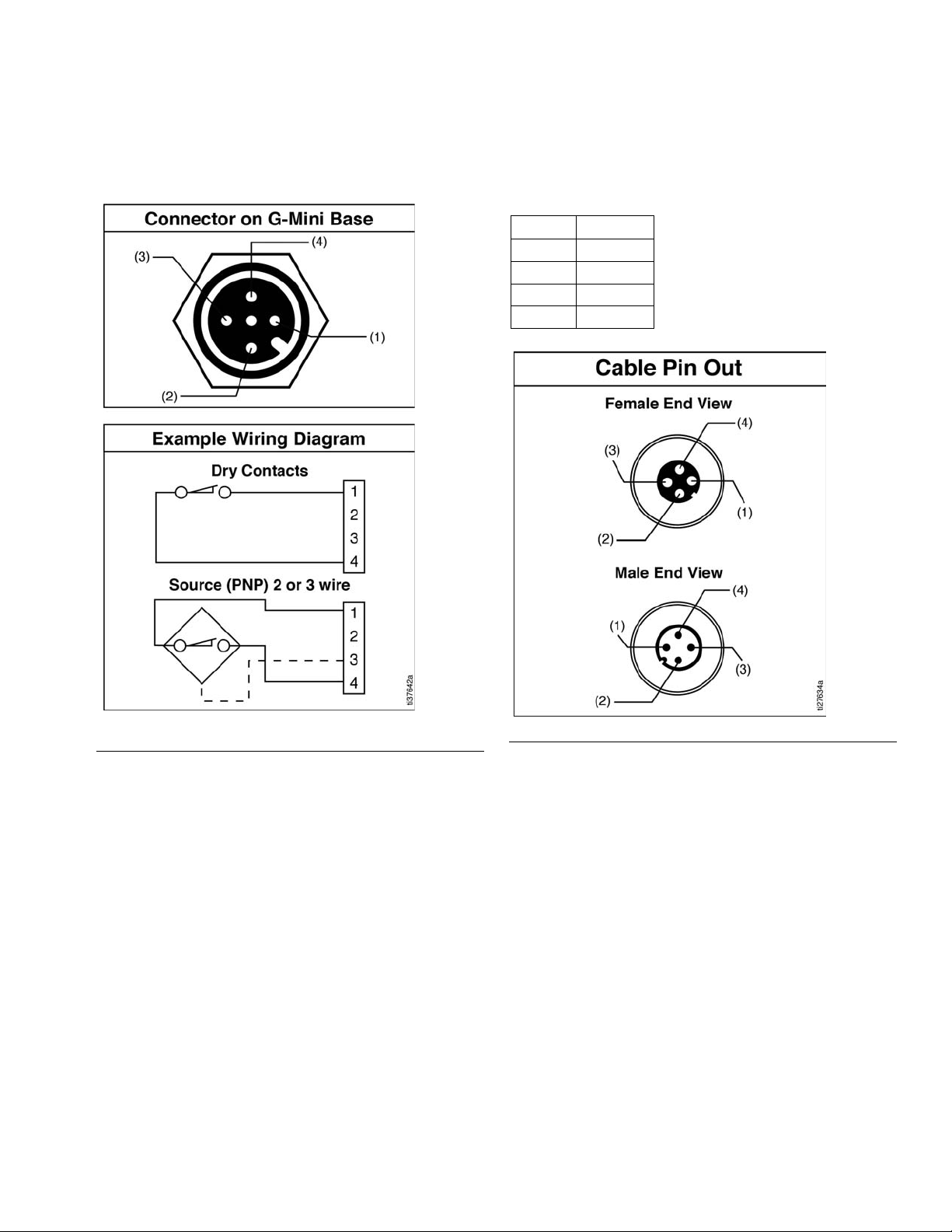
Divider Valve Indicator Cycle Inputs (M12)
See Technical Specifications, page 36 for ratings.
Part No. 124333: Cable Pin Out (M12) for
5 m Cable
Wire Colors (F
IG. 13)
Item No. Color
1Brown
2White
3Blue
4Black
FIG. 12
3A6714C 13
FIG. 13
Page 14

Installation
Manual Run Button
Part No. Description
25C981 Manual Run Button, 12V
25C982 Manual Run Button, 24V
Manual Run Button DIN DC
See Technical Specifications, page 36 for ratings
Pin Out
1LED2LED +
3Button
4 Not Used
FIG. 14
Proximity Switch
NOTE: Reference ILE buyer’s guide for appropriate PNP
proximity switches and cables.
14 3A6714C
Page 15

Setup
Setup
Pressure Relief Procedure
Follow the Pressure Relief Procedure whenever
you see this symbol.
This equipment stays pressurized until pressure is
manually relieved. To help prevent serious injury from
pressurized fluid, such as skin injection, splashing
fluid and moving parts, follow the Pressure Relief
Procedure when you stop dispensing and before
cleaning, checking, or servicing the equipment.
Disconnect and isolate all power supplies.
Relieve pressure in the system using two wrenches
working in opposite directions on the pump element and
pump element fitting to slowly loosen fitting only until the
fitting is loose and no lubricant or air is leaking from
fitting.
Connect to Auxiliary Fittings
NOTICE
Do not attach unsupported equipment to auxiliary fittings such as fill ports and pump element. Attaching
unsupported equipment to these fittings can result in
irreparable housing damage.
• Always use two wrenches working in opposite directions when connecting anything to pump element or
auxiliary fittings. See F
• Torque pump element fittings to 50 in-lb (5.6 N•m).
• Torque pump element to 65 in-lb (7.3 N•m) when
connecting to the housing.
Pressure Relief Valves
IG. 15 for an example.
NOTE: When loosening the pump element fitting, do not
loosen the pump element. Loosening the pump element
changes the output volume.
F
IG. 15
To prevent over-pressurization, which can result in
equipment rupture and serious injury, a pressure
relief valve appropriate for the lubrication system
must be installed close to each pump outlet to alleviate unintended pressure rises in the system and protect the pump from damage.
• Only use a pressure relief valve that is rated for
no more than the working pressure of any component installed in the system.
• Install a pressure relief valve before any auxiliary
fitting.
NOTE: A pressure relief valve may be purchased from
Graco. See Pressure Relief Valves, page 15.
Pressure Relief Valves
Part No. Description
571028 Kit, Adj. Pressure Relief
3A6714C 15
Page 16

Setup
Set Pump Outlet Volume
1. Follow the Pressure Relief Procedure, page 15.
2. Use a wrench and turn the pump element counterclockwise to remove the entire pump element.
4. Re-install the pump element into the pump base,
ensuring that the first thread of the element
engages correctly.
NOTE: It may be necessary to repeat the pump outlet
volume setup procedure after the pump is operating to
adjust the volume of the dispensed fluids.
5. Use a wrench and tighten the pump element fitting.
Torque to 50 in-lb (5.6 N•m).
NOTE:
• The dispensed volume amount varies depending
upon external conditions, such as lubricant
temperature and back pressure from downstream
connections.
• Use the volume adjustment process in conjunction
with setting the ON time of the pump to control the
output volume.
• The volume adjustment process should be used as
a starting point for dispensing the desired lubrication
volume.
FIG. 16
3. Replace the current spacer with the desired spacer.
Thickness Output Volume/Minute
Spacers
25N814 1.5 0.183 3.0
18A317 4.6 0.0915 1.5
NOTE: A spacer is required for operation. Only one
Graco spacer can be used at a time. The pumps from
the factory have a spacer (25N814) installed on the
pump element. Pump Element Kits (page 30) come
with a spacer. The spacer may be replaced depending
upon the required output volume.
mm Cubic In. Cubic cm
Load Grease
To ensure optimal performance from the pump:
• Use only NLGI #000 - #2 greases appropriate for
the application, automatic dispensing, and the
equipment’s operating temperature. Consult with the
machine and lubrication manufacturers for details.
• Fill the reservoir using a hand operated pump,
pneumatic pump or electric transfer pump.
• Do not overfill.
• Do not operate the pump without having a reservoir
attached.
NOTICE
• Always clean fitting (E) with a clean dry cloth
prior to filling the reservoir. Dirt and/or debris
can damage pump and/or lubrication system.
• Use care when filling the reservoir using a pneumatic or electric transfer pump to avoid pressurizing and breaking the reservoir.
16 3A6714C
Page 17

Setup
E
B
1. Connect the fill hose to the Zerk Inlet Fill Fitting (E)
(F
IG. 17).
FIG. 17
NOTE: The venting tube (B) should not be used as an
overfill indicator (F
IG. 18).
2. For higher viscosity fluids, start the pump, per the
controller instructions, to rotate the stirring paddle
during filling to prevent air pockets from forming in
the grease.
For models using an external controller, start the pump
operation following the controller instructions.
3. Fill the reservoir with NLGI grease to the MAX line
(F
IG. 18).
FIG. 18
4. Remove the fill hose.
Change Greases
Always use compatible grease when changing grease.
3A6714C 17
Page 18

Setup
Priming
It is not necessary to prime the pump every time the
pump is filled. The pump only requires priming the first
time it is used, or if it is allowed to run dry.
1. Loosen the pump element fitting (F
IG. 19).
NOTE: When loosening the pump element fitting, do not
loosen the pump element. Loosening the pump element
changes the output volume and causes leakage.
FIG. 19
FIG. 20
3. Tighten the pump element fitting using two
wrenches working in opposite directions (F
IG. 21).
2. Only run the pump until air is no longer dispensed
with the lubricant out of element fitting (F
IG. 20).
FIG. 21
18 3A6714C
Page 19

Non Controller Operation
Non Controller Operation
The pump can be controlled using an external, user supplied, controller.
NOTE:
• When using an external controller, Pump ON (Run)
Time should be set for no longer than 30 minutes.
• In most cases, Pump OFF (Rest) Time should be
twice as long as Pump ON (Run) time. If alternative
ON / OFF times are required, contact Graco Customer Service for assistance.
Typical Low-Level Output Response with Low-Level Fluid
Low-Level Output Option
Models 25R800, 25R802, 25R807 and 25R809
Pumps without controllers include a Low-Level Output
Option. The low-level signal is monitored across PINS 4
and 5. For the locations and wiring information for PINS
4 and 5, see the Wiring and Installation Diagrams,
page 9.
Model 25R820, 25R822, 25R827 and 25R829
See the Wiring and Installation Diagrams, page 9.
FIG. 22
3A6714C 19
Page 20
Controller Operation
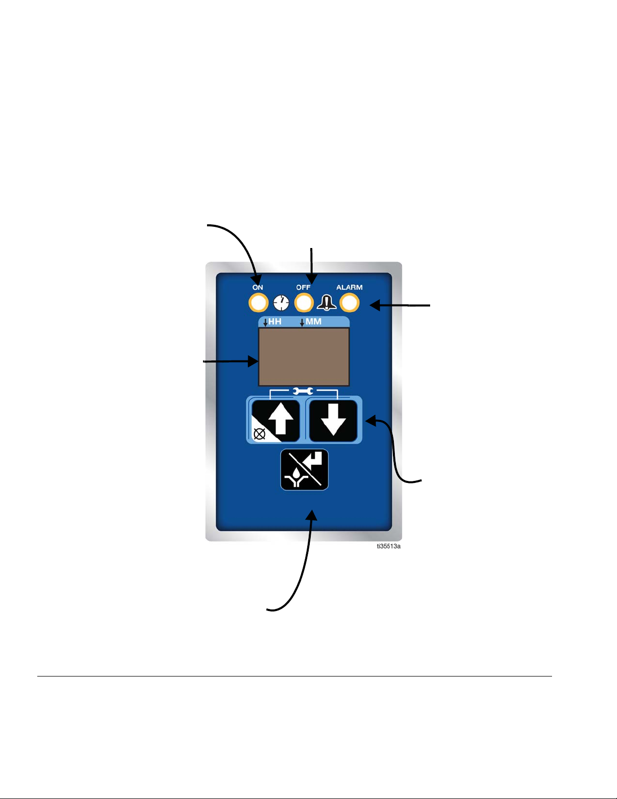
DISPLAY
• Upon entering SETUP MODE, the
first digit in the display begins to
blink.
• In RUN MODE, the programmed
ON TIME, CYCLES or OFF TIME
displays and counts down to zero.
ON TIME
• In SETUP MODE, the LED illumi-
nates when ON TIME duration or
cycles are set up.
• A dot illuminates under MM on the
display.
• The ON TIME range is 1 to 30
minutes, or 1 to 99 cycles.
• In RUN MODE, the LED illuminates
during the ON TIME sequence.
ALARM
The LED illuminates when
an alert / alarm event occurs.
Most alerts/alarms occur
during ON TIME MODE.
However, if a Low-Level alert
triggers near the end of an
ON TIME cycle, the alert will
display while the controller is
in OFF TIME MODE. A software error occurring when
the controller is operating in
the OFF TIME MODE will
also activate the alarm LED.
MANUAL RUN / ENTER
• In SETUP MODE, press this button to save the
entry, move the cursor in the display one field to the
right or to the next setup step.
• In RUN MODE, press this button to start a manual
run cycle.
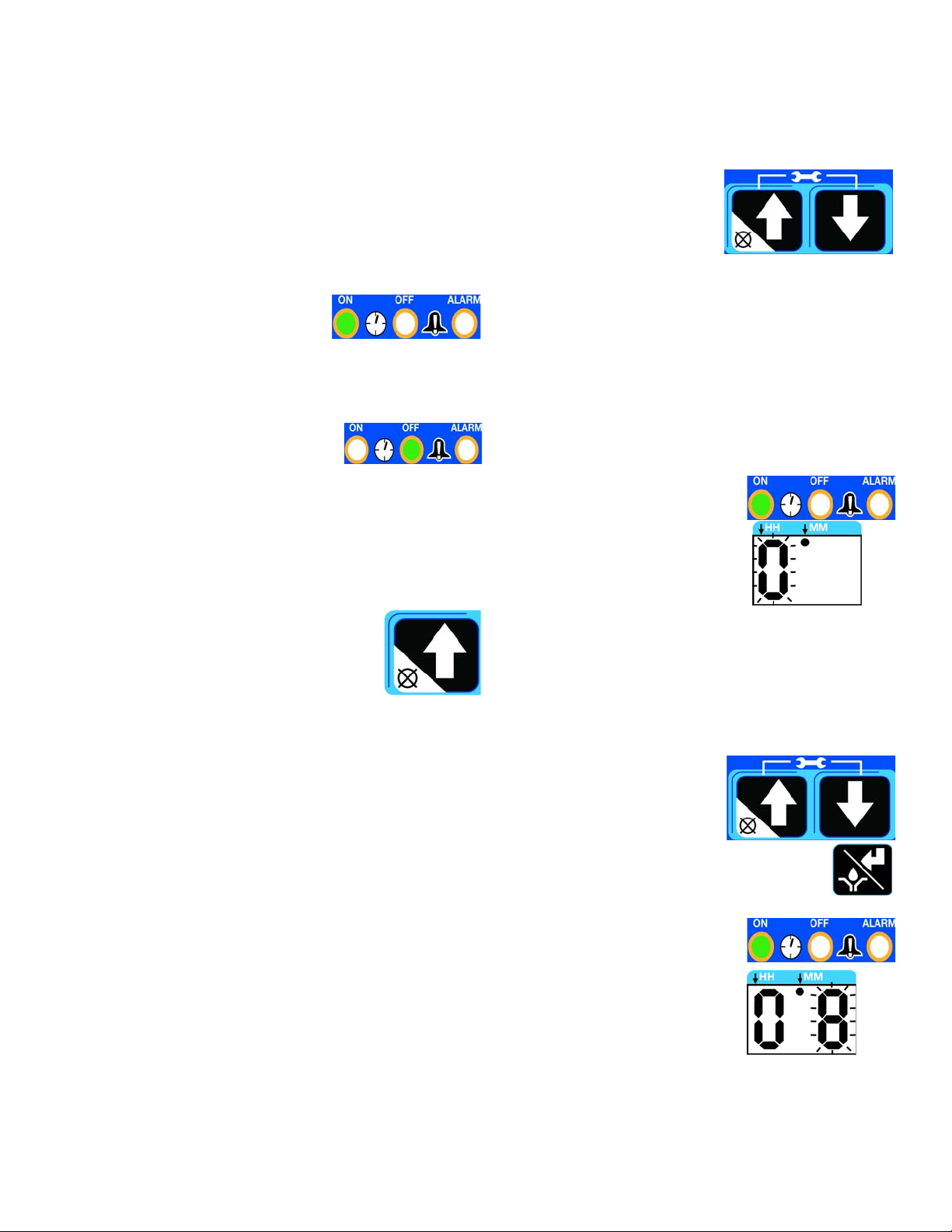
UP and DOWN ARROWS
• Hold both the UP and
DOWN arrow buttons
together for 3 seconds to
enter SETUP MODE.
• In SETUP MODE, the UP
and DOWN arrows
increase or decrease time
and cycle setting values
shown on the display.
• In RUN TIME MODE,
pressing the UP
arrow/CANCEL button terminates the lubrication
period.
OFF TIME
• In SETUP MODE, the LED illuminates when OFF TIME duration is
set up.
• A dot illuminates under HH on the display.
• The OFF TIME range is 15 / 30 / 45 min or 1 to 99 hours.
• The LED illuminates when OFF TIME sequence is running.
Controller Operation
Control Panel Overview (FIG. 23)
FIG. 23
20 3A6714C
Page 21
Controller Operation
The controller operates in two modes; RUN MODE and
SETUP MODE. Each mode has multiple functions.
RUN MODE
RUN MODE performs two functions while monitoring
Alert/Alarm conditions: ON TIME and OFF TIME.
• In ON TIME the motor is
running and the lubrication
is delivered. ON TIME can
be configured to be active
for a period of time in minutes or a period of lube
cycles (cycle or proximity switch is required).
• In OFF TIME the motor is not
running. This is a period
where no lubrication is delivered. OFF TIME can be configured for 15 / 30 / 45 min. or 1 to 99 hours.
By default, units with controllers are set to operate with
an ON TIME period of five (5) minutes and an OFF
TIME period of one (1) hour.
Once an ON TIME lubrication period
begins, it can be terminated by pressing
the UP arrow/CANCEL button.
While in RUN MODE the controller
monitors Alert/Alarm conditions. See
Alert and Alarm Scenarios, page 27 for full descriptions.
SETUP MODE
Press both the UP and
DOWN arrow buttons
together for 3 seconds to
enter SETUP MODE.
The first digit on the display
begins to blink. This indicates SETUP MODE. After
entering SETUP Mode, if no activity is detected, after 60
seconds a timeout occurs and the controller resumes in
RUN MODE.
ON TIME Configuration (Minutes)
The first configuration in SETUP MODE is programming
the ON TIME.
Notice the following on the controller:
- The LED next to the
Clock in the ON field illuminates.
- The first digit on the display begins to blink.
- A dot on the display
under the MM illuminates.
This confirms that the controller is ready for the first digit
to be configured for ON TIME in Minutes (MM).
NOTE: The ON TIME can be configured between 1 to
30 minutes.
1. Press the UP or DOWN
arrows to select the first
digit.
2. Press the ENTER button
to save the selection.
After the ENTER button is
pressed, the second digit begins
to blink. The ON LED and MM
dot remains lighted.
This confirms that the second
digit for ON TIME is being configured in Minutes (MM).
3A6714C 21
Page 22

Controller Operation
3. Press the UP or DOWN
arrows to select the second digit.
4. Press the ENTER button
to save the selection.
The controller automatically switches to OFF TIME configuration.
ON TIME Configuration (Cycles)
NOTE: The proximity switch accessory must be installed
and Cycle Count enabled in Advanced Programming
(page 23) before the number of cycles can be configured in SETUP MODE.
Notice the following on the controller:
- The LED next to the
Clock in the ON field illuminates
- The display reads “CY”
to identify that the ON
TIME is configured for
Cycles Counts.
NOTE: The number of cycles counts can range from 1
to 99.
1. Press the ENTER button to
advance the display.
After the ENTER button is
pressed, the second digit
begins to blink. The ON LED
remains lighted.
This confirms that the second
digit for ON TIME is being configured in Minutes (MM).
4. Press the UP or DOWN
arrows to select the second digit.
5. Press the ENTER button to save the
selection.
The controller automatically switches to OFF TIME configuration.
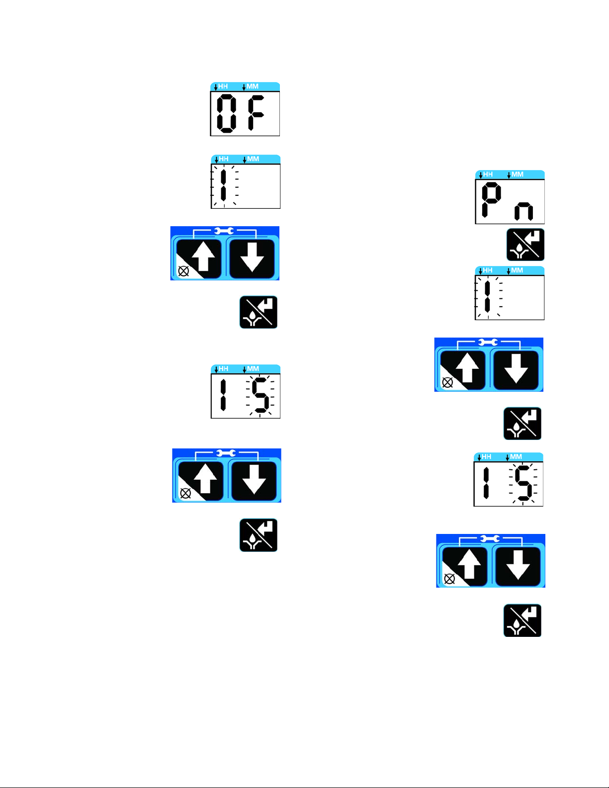
OFF TIME Configuration (Min./Hrs)
Notice the following on the controller:
- The LED next to the
Clock in the OFF
field is lighted.
- The first digit on the
display begins to
blink.
- A dot on the display
under the HH illuminates.
The first digit on the display
begins to blink. This confirms
that the controller is ready for
the cycle count to be configured.
2. Press the UP or DOWN
arrows to select the first
digit.
3. Press the ENTER button to save the
selection.
22 3A6714C
This confirms that the controller is ready for the first digit
to be configured for OFF TIME in Hours (HH).
NOTE: The OFF TIME must be configured between 15
min, and 99 hours.
1. Press the UP or Down
arrows to select the first
digit.
2. Press the ENTER button
to save the selection.
Page 23

Controller Operation
After the ENTER button is
pressed, the second digit
begins to blink. The OFF
LED and HH dot remain
lighted.
This confirms that the second digit for OFF TIME is
being configured in Hours
(HH).
3. Press the UP or DOWN
arrows to select the second digit.
4. Press the ENTER button
to save the selection.
The controller automatically switches to RUN MODE.
ADVANCED PROGRAMMING
The Seven Advanced Programming Menu Descriptions
are:
• A1 - PIN Entry Enable/Setting Up the PIN Code,
page 23
• A2 - Prelube and Delay, page 25
• A3 - Low-Level Alert Duration, page 25
• A4 - Missed Cycle Threshold, page 25
• A5 - Low-Level Power Cycle Retry, page 25
• A6 - Low-Level Alert Enable, page 25
• A7 - Cycle Count Enable, page 25
To access ADVANCED PROGRAMING:
1. Press both the UP and
DOWN arrow buttons for
3 seconds to enter
SETUP MODE.
After entering ADVANCED PROGRAMMING, if no activity is detected for 60 seconds, a timeout occurs and the
controller resumes RUN MODE.
Press the ENTER button to advance to the
configurable portion of the specific settings.
1. Press the UP or DOWN
arrows to configure the
selection.
For ON or OFF selection:
-ON: UP arrow
- OFF: DOWN arrow
2. After completing configuration, press the
ENTER button to save and proceed to
the next ADVANCED PROGRAMMING
settings.
After all of the ADVANCED PROGRAMMING settings
are configured, press the ENTER button to return the
controller to RUN MODE.
Advanced Programming Menu Descriptions
A1 – PIN Entry Enable/Setting Up the PIN Code
A PIN Code provides additional controller security by
requiring that a PIN Code be entered before gaining
access to SETUP MODE.
NOTE: The PIN Code can be configured to be any number between (and including) 00 and 99.
To set up the PIN Code:
1. Follow Steps 1 and 2 of ADVANCED PROGRAMMING, (page 23).
2. When A1 appears on the display, press
the ENTER button. Either On (PIN Code
ON) or OF (PIN Code OFF) displays.
2. In SETUP MODE, press and hold
the UP arrow for 10 seconds.
The display reads A1. This confirms
that the controller is in the
ADVANCED PROGRAMMING settings.
3A6714C 23
• On (ON) - Select On to configure the controller to
require that a PIN Code be entered prior to
accessing SET UP Mode.
-
Page 24
Controller Operation
- OF (OFF) - Select OF to configure the controller to not
require a PIN code. Press the
ENTER button again to set
the OF (OFF) option.
3. The first digit on the display
begins to blink. This confirms
that the controller is ready to
select the first number of the PIN
Code.
4. Press the UP or Down
arrows to select the first
digit.
5. Press the ENTER button to save the
selection.
After the ENTER button is pressed,
the second digit begins to blink.
Entering a PIN Code in the Controller
After the controller is configured for PIN entry, to access
SETUP MODE:
1. Follow Steps 1 and 2 of ADVANCED PROGRAM-
MING, (page 23).
2. Pn appears on the display.
3. Press the ENTER button to
advance the display.
4. The first digit on the display
begins to blink. This confirms
that the controller is ready for the
first number of the PIN Code to
be entered.
5. Press the UP or Down
arrows until the first digit
of the PIN Code displays.
This confirms that the second digit for
the PIN Code is ready to be configured.
6. Press the UP or Down
arrows to select the second digit.
7. Press the ENTER button to save the
selection.
8. The controller automatically advances to the A2
screen.
6. Press the ENTER button to save the
entry.
7. After pressing the ENTER button, the second digit begins to
blink. This confirms that the controller is ready for the second
number of the PIN Code to be
entered.
8. Press the UP or Down
arrows until the second
digit of the PIN Code displays.
9. Press the ENTER button to save the
entry.
10. The ON TIME configuration screen displays. See
SETUP MODE, ON TIME Configuration (Minutes), page 21 for additional information.
24 3A6714C
Page 25

Controller Operation
A2 – Prelube and Delay
The Prelube Delay option configures the controller to set
the amount of time before the Prelube cycle begins. The
duration of time begins after power has been restored to
the controller. This value can range from 0 to 60 minutes
(default: 0).
The Prelube function determines operation of the pump
when power is applied. It can be set to ON or OFF.
• OF (OFF) (default) – The unit resumes at the point
in the lubrication cycle it was at when power was
disengaged.
• On (ON) – The unit begins a pump cycle once
power is restored.
When On is selected and the Enter button is pressed,
the controller is ready for a Prelube delay to be configured. See ADVANCED PROGRAMMING instructions,
page 23.
A3 – Low-Level Alert Duration
The Low-Level Alert Time configures the controller to
set the duration of time that a Low-Level Alert exists with
the pump running before escalating to an Alarm.
The Low-Level Auto Clear is an OF (OFF) or On (ON)
selection.
• OF (OFF) (default) – Upon power cycle, the controller will remain in its current Low-Level Alarm state.
• On (ON) – Upon power cycle, the controller will
begin a lubrication cycle to determine if a Low-Level
condition still exists.
See ADVANCED PROGRAMMING instructions, page
23.
A6 – Low-Level Alert Enable
The Low-Level Warning Enable feature configures the
controller to trigger a Low-Level Alert prior to the escalation of an Alarm.
The Low-Level Warning Enable is an OF (OFF) or On
(ON) selection.
• OF (OFF) (default) – Low-Level conditions are
immediately escalated to Alarm status.
• On (ON) – Low-Level conditions are first reported as
an Alert for the duration of setting A3, at which point
they escalate to an Alarm.
The Low-Level Alert Time can range from 1 to 5 minutes
(default: 3). To configure the Low-Level Alert Time, see
ADVANCED PROGRAMMING instructions, page 23.
A4 – Missed Cycle Threshold
While operating in Cycle Mode, the Cycle Alarm Threshold configures the controller to set the number of consecutively missed Cycles allowed before activating an
alarm.
The Cycle Alarm Threshold can range from 0-99 cycles
(default:0). To configure the Cycle Alarm Threshold, see
ADVANCED PROGRAMMING instructions, page 23.
A5 – Low-Level Power Cycle Retry
When set to ON, the Low-Level Auto Clear feature
allows the controller to attempt to automatically clear a
Low-Level Alarm during the power cycle. This feature is
only used when a controller has the power removed
while in a Low-Level Alarm state.
See ADVANCED PROGRAMMING instructions, page
23.
A7 – Cycle Count Enable
The Cycle Lubrication Enable feature configures the
controller to use Cycle Counts to monitor the duration of
a lubrication period and enables the M12 Cycle Indicator
Connector.
The Cycle Lubrication Enable is an OF (OFF) or On
(ON) selection.
• OF (OFF) (default) – The lubrication period will be
monitored in minutes.
• On (ON) – The lubrication period is monitored in
cycles. This requires the addition of a proximity
switch. The number of cycles must also be configured in SET UP mode (page 21).
See ADVANCED PROGRAMMING instructions, page
23.
3A6714C 25
Page 26

Alerts and Alarms
Alerts and Alarms
The controller monitors and displays two types of
events: Alerts and Alarms.
Alerts
Alerts do not cause the lubrication cycle to stop. These
events are automatically cleared based upon the alert
received.
An amber LED illuminates under ALARM on
the display when an
Alert occurs. See Alert
and Alarm Scenarios on page 27 for a description of
Alerts that could occur.
Alarms
Alarms cause the lubrication cycle to stop. Alarms can
trigger immediately or can be the result of an escalated
Alert. Alarms must be cleared immediately.
A red LED illuminates
under ALARM on the
display when an Alarm
occurs. See the Alert
and Alarm Scenarios table on page 27 for a description of Alarms that could occur.
When an Alarm is triggered, any active lubrication cycle
will be terminated. The display begins to count up to
identify how long the Alarm condition has been present.
The counter begins in minutes, then changes to hours,
with a limit of 99 hours.
See ADVANCED PROGRAMMING, page 23 for additional information about configuring the controller for
Alerts and Alarms.
26 3A6714C
Page 27

Alert and Alarm Scenarios
The following pages describe the most likely alerts and alarms:
Alarm Type Display What it Indicates Solution
Low-Level There is a low-level of lubricant in
the reservoir
Add lubricant to reservoir.
An alert will auto-clear.
An alarm must be reset by
pressing and holding the
Cancel Button for 4 seconds.
Alerts and Alarms
Cycle The cycle was not completed in 4
minutes.
Over
Current
The measured motor current is
above the maximum operating level.
The motor turns off and a new lube
cycle is not allowed to be initiated.
Check for a plugged or broken line, or
other component failure such as a divider
valve.
An alert will auto-clear.
An alarm must be reset by
pressing and holding the
Cancel Button for 4 seconds.
Check to make sure that the system is
operating correctly. A blocked line could
create excessive motor current.
Examine the pump to verify it is rotating
properly.
An alarm must be reset by
pressing and holding the
Cancel Button for 4 seconds.
System
Fault
3A6714C 27
An internal fault has occurred.
The controller may not be recoverable from this state.
Attempt a power cycle of the device.
If the alarm does not clear, contact Graco
Customer Service.
Page 28
Troubleshooting
Troubleshooting
1. Follow Pressure Relief Procedure, page 15,
before checking or repairing.
Problem Cause Solution
Unit does not power on. Incorrect/loose wiring Refer to Installation instructions,
page 6.
Lubricant leaks past the seal located
on the bottom of the reservoir.
The external controller is
functioning, but the unit is not
pumping during the ON cycle.
The follower plate is not moving
downward.
After wiring and installing the
equipment, the pump is not working.
Tripped external fuse due to internal
component failure.
Tripped external fuse from using
grease with an inadequate
temperature rating in a cold
environment.
Seal was not installed correctly. Replace seal.
Reservoir is being pressurized
during filling.
Motor failure. Replace the motor.
Air is trapped in the reservoir
between the follower plate and the
lubricant.
The pump is wired incorrectly. Rewire the pump following Wiring
Contact Graco Customer Service.
Replace lubricant with a lubricant
rated for environmental conditions
and application.
Replace fuse.
Ensure that the vent tube is not
plugged.
If the problem persists, contact
Graco Customer Service or your
local Graco distributor for
assistance.
Add grease following the Load
Grease instructions, page 16.
Purge any air from the reservoir.
and Installation Diagrams, page 9.
28 3A6714C
Page 29

Maintenance
Maintenance
Frequency Component Required Maintenance
Daily and at Refill Fill Fittings Keep all of the fittings clean using a clean dry cloth.
Dirt and/or debris can damage the pump and/or the
lubrication system.
Daily Pump Unit and Reservoir Keep pump unit and reservoir clean using a clean dry
cloth.
Monthly External Wiring Harness Verify external harnesses are secure.
3A6714C 29
Page 30

Repair
Repair
All electrical wiring must be done by a qualified
electrician and comply with all local codes and
regulations.
Reservoir Kits
Kit No. Description
26C943 Kit Replacement, Reservoir, 1L
26C945 Kit Replacement, Reservoir, 0.5L
Kit Replacement, Reservoir, Follower
26C944
26C946
Plate, 1L
Kit Replacement, Reservoir, Follower
Plate, 0.5L
Pump Element Kits
Kit No. Description
Standard G-Mini Pump Element;
26C947
26C948
Output: 3 cc/min.
Alternative G-Mini Pump Element;
Output: 1.5 cc/min.
30 3A6714C
Page 31

Parts
Torque to 23 in-lb (2.6 N•m)
3
Torque to 13 in-lb (1.5 N•m)
1
Torque to 65 in-lb (7.3 N•m)
2
1a
1b
2
3a
3b
4a, 4b
46
6
12
11
19
20
22
23
24
25a, 25b
28
32a, 32b
33
34
38
39
41a, 41b
42
43
44
45
19
19
1
1
2
3
3
4
50
Torque to 7 in-lb (0.8 N•m)
4
63a, 63b
65
64
4
66
Parts
3A6714C 31
Page 32
Parts
Part No./Description
Ref. Part Description Qty.
Reservoir, 1.0 Liter, included in kits
26C943, 26C944
1a
1b
2
3a
3b
4a
4b
6
11 Blade, agitator
12 Washer, paddle, ID8/OD16
19 Screw, ST4.2
20
Model 25R800, 25R801, 25R802,
25R803, 25R804, 25R805, 25R806,
25R820, 25R821, 25R822, 25R823,
25R824, 25R825, 25R826
Reservoir, 0.5 Liter, included in kits
26C945, 26C946
Model 25R807, 25R808, 25R809,
25R810, 25R827, 25R828, 25R829,
25R830
Label, max fill, included in kits
26C943, 26C944
Model 25R800, 25R801, 25R802,
25R803, 25R804, 25R805, 25R806,
25R820, 25R821, 25R822, 25R823,
25R824, 25R825, 25R826
Label, branding, 1L, included in kits
26C943, 26C944
Model 25R800, 25R801, 25R802,
25R803, 25R804, 25R805, 25R806,
25R820, 25R821, 25R822, 25R823,
25R824, 25R825, 25R826
Label, branding, 0.5 Liter, included in
kits 26C945, 26C946
Model 25R807, 25R808, 25R809,
25R810, 25R827, 25R828, 25R829,
25R830
Spring, compr., 1.0 Liter Reservoir,
included in kit 26C944
Model 25R800, 25R801, 25R802,
25R803, 25R804, 25R805, 25R806,
25R820, 25R821, 25R822, 25R823,
25R824, 25R825, 25R826
Spring, compr., 0.5 Liter Reservoir,
included in kit 26C946
Model 25R807, 25R808, 25R809,
25R810, 25R827, 25R828, 25R829,
25R830
Plate, follow, included in kits 26C944,
26C946
Seal, Reservoir, included in kits
26C943, 26C944, 26C945, 26C946
1
1
1
1
1
1
1
1
1
3
10
1
Ref. Part Description Qty.
Pump element, assy, included in kits
26C947, 26C948
Model 25R805, 25R825
Pump element, assy, included in kits
26C947, 26C948
22
23 100721 Plug, 1/4 npt, HEX socket
24 555888 Nipple
25a
25b
28 PCB, Board, assy, Compact Pump
32a Motor, 24VDC
32b Motor, 12VDC
33 Seal, bottom cover
34 Cover, bottom
38 111139 O-ring
39 Label, Series
41a
41b
42
43
44
45 Base, Pump
Model 25R800, 25R801, 25R802,
25R803, 25R804, 25R806, 25R807,
25R808, 25R809, 25R810, 25R820,
25R821, 25R822, 25R823, 25R824,
25R825, 25R826, 25R827, 25R828,
25R829, 25R830
Label, overlay, BLK
Model 25R800, 25R802, 25R807,
25R809, 25R820, 25R822, 25R827,
25R829
Label, overlay, controller version
Model 25R801, 25R803, 25R804,
25R805, 25R806, 25R808, 25R810,
25R821, 25R823, 25R824, 25R825,
25R826, 25R828, 25R830
CPC connector, Power and Low Level
Model 25R800, 25R802, 25R807,
25R809
CPC connector, Power and Manual
Run Button
Model 25R801, 25R803, 25R804,
25R905, 25R806, 25R808, 25R810
Washer, lock, M12
Model 25R801, 25R803, 25R804,
25R805, 25R806, 25R808, 25R810,
25R821, 25R823, 25R824, 25R825,
25R826, 25R826, 25R830
M12 connector, cycle feedback input
Model 25R801, 25R803, 25R804,
25R805, 25R806, 25R808, 25R810,
25R821, 25R823, 25R824, 25R825,
25R826, 25R828, 25R830
Plug, M12
Model 25R801, 25R803, 25R804,
25R805, 25R806, 25R808, 25R810,
25R821, 25R823, 25R824, 25R825,
25R826, 25R828, 25R830
2
1
2
1
1
1
1
1
1
1
1
4
1
1
1
1
1
1
1
32 3A6714C
Page 33

Ref. Part Description Qty.
Plug, M20
Model 25R800, 25R801, 25R802,
25R803, 25R804, 25R806, 25R807,
46
50 16A579 Label, Warning
63a
63b
64 DIN connector, Power Input
65
66
25R808, 25R809, 25R810, 25R820,
25R821, 25R822, 25R823, 25R824,
25R826, 25R827, 25R828, 25R829,
25R830
DIN connector, Low Level
Model 25R820, 25R822, 25R827,
25R829
DIN connector, Manual Run Button
Model 25R821, 25R823, 25R824,
25R825, 25R826, 25R828, 25R830
Screw, Self-Tap
Model 25R820-25R830
Cap
Model 25R820-25R830
1
1
1
1
1
8
2
Parts
Replacement safety labels, tags, and cards are
available at no cost.
3A6714C 33
Page 34
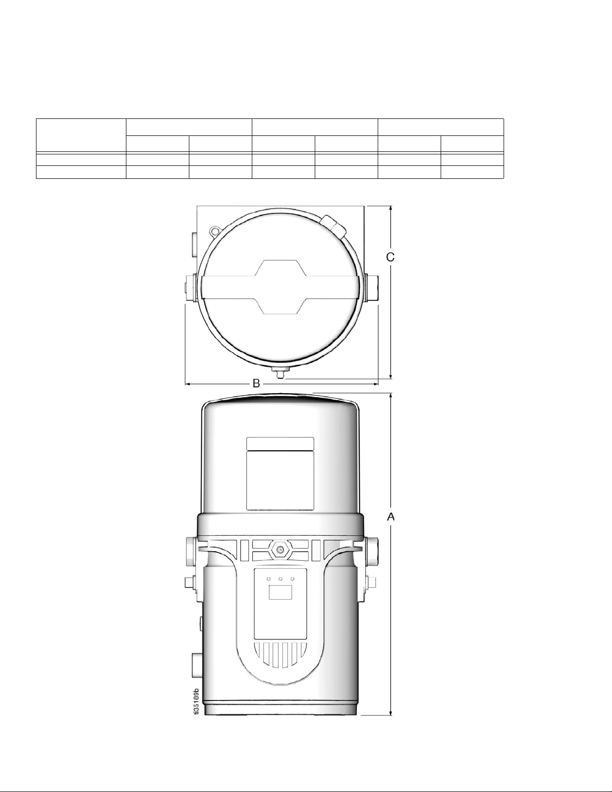
Dimensions
Dimensions
Model
0.5L 10.9 27.7 6.97 17.7 6.57 16.7
1L 12.2 31.0 6.97 17.7 6.57 16.7
Height - A Width - B Depth - C
Inches cm Inches cm Inches cm
34 3A6714C
Page 35

Dimensions
Pump Mount
Universal Bracket Mount
CSP Valve Bracket Mount
3A6714C 35
Page 36

Technical Specifications
Technical Specifications
G-Mini Pump
US Metric
Maximum fluid working pressure 4061 psi 28 MPa, 280 bar
Power
12 VDC 9-16 VDC; 9.5 A current, 114 W, inrush/locked rotor 12 A
24 VDC 18-32 VDC; 6.5 A current, 156 W, inrush/locked rotor 7.5 A
Inputs - Proximity Switch PNP Style Switch and Cable Only
Pump Voltage: 12 VDC 11 mA at 12 VDC
Pump Voltage: 24 VDC 22 mA at 24 VDC
Outputs - Low Level
Contact Rating
Switch Rating
Switching Current 0.5 A maximum
Carry Current 1.2 A maximum
Outputs - Manual Run Button
Pump Voltage: 12 VDC 11 mA at 12 VDC
Pump Voltage: 24 VDC 22 mA at 24 VDC
Pump Output
Pump Outlet 1/4 in. NPT female
Reservoir Size 0.5 L
IP Rating IP69K
Working Temperature*
Non-Heater Model
Heater Model
Weight
Wetted parts
Sound data
100 W maximum
200 VDC maximum
3.0 cc minute at room temperature with 4061 psi (28 MPa,
280 bar) back pressure
1.0 L
5°F to 158°F -15°C to 70°C
-40°F to 158°F -40°C to 70°C
8.8 lb 4 kg
carbon steel, alloy steel, stainless steel, nitrile rubber
(buna-N), bronze, nickel plated alnico, chemically lubricated
acetal, aluminum, PTFE, amorphous polyamide, nylon 6/6
(PA)
<60dB
*Achieving the minimum working temperature is contingent on using a temperature compliant grease in an appropriately designed
system.
36 3A6714C
Page 37

Technical Specifications
California Proposition 65
WARNING: This product can expose you to chemicals known to the State of California to
cause cancer and birth defects or other reproductive harm. For more information, go to
www.P65warnings.ca.gov.
3A6714C 37
Page 38

Graco Standard Warranty
Graco warrants all equipment referenced in this document which is manufactured by Graco and bearing its name to be free from defects in
material and workmanship on the date of sale to the original purchaser for use. With the exception of any special, extended, or limited warranty
published by Graco, Graco will, for a period of twelve months from the date of sale, repair or replace any part of the equipment determined by
Graco to be defective. This warranty applies only when the equipment is installed, operated and maintained in accordance with Graco’s written
recommendations.
This warranty does not cover, and Graco shall not be liable for general wear and tear, or any malfunction, damage or wear caused by faulty
installation, misapplication, abrasion, corrosion, inadequate or improper maintenance, negligence, accident, tampering, or substitution of
non-Graco component parts. Nor shall Graco be liable for malfunction, damage or wear caused by the incompatibility of Graco equipment with
structures, accessories, equipment or materials not supplied by Graco, or the improper design, manufacture, installation, operation or
maintenance of structures, accessories, equipment or materials not supplied by Graco.
This warranty is conditioned upon the prepaid return of the equipment claimed to be defective to an authorized Graco distributor for verification of
the claimed defect. If the claimed defect is verified, Graco will repair or replace free of charge any defective parts. The equipment will be returned
to the original purchaser transportation prepaid. If inspection of the equipment does not disclose any defect in material or workmanship, repairs will
be made at a reasonable charge, which charges may include the costs of parts, labor, and transportation.
THIS WARRANTY IS EXCLUSIVE, AND IS IN LIEU OF ANY OTHER WARRANTIES, EXPRESS OR IMPLIED, INCLUDING BUT NOT LIMITED
TO WARRANTY OF MERCHANTABILITY OR WARRANTY OF FITNESS FOR A PARTICULAR PURPOSE.
Graco’s sole obligation and buyer’s sole remedy for any breach of warranty shall be as set forth above. The buyer agrees that no other remedy
(including, but not limited to, incidental or consequential damages for lost profits, lost sales, injury to person or property, or any other incidental or
consequential loss) shall be available. Any action for breach of warranty must be brought within two (2) years of the date of sale.
GRACO MAKES NO WARRANTY, AND DISCLAIMS ALL IMPLIED WARRANTIES OF MERCHANTABILITY AND FITNESS FOR A
PARTICULAR PURPOSE, IN CONNECTION WITH ACCESSORIES, EQUIPMENT, MATERIALS OR COMPONENTS SOLD BUT NOT
MANUFACTURED BY GRACO. These items sold, but not manufactured by Graco (such as electric motors, switches, hose, etc.), are subject to
the warranty, if any, of their manufacturer. Graco will provide purchaser with reasonable assistance in making any claim for breach of these
warranties.
In no event will Graco be liable for indirect, incidental, special or consequential damages resulting from Graco supplying equipment hereunder, or
the furnishing, performance, or use of any products or other goods sold hereto, whether due to a breach of contract, breach of warranty, the
negligence of Graco, or otherwise.
FOR GRACO CANADA CUSTOMERS
The Parties acknowledge that they have required that the present document, as well as all documents, notices and legal proceedings entered into,
given or instituted pursuant hereto or relating directly or indirectly hereto, be drawn up in English. Les parties reconnaissent avoir convenu que la
rédaction du présente document sera en Anglais, ainsi que tous documents, avis et procédures judiciaires exécutés, donnés ou intentés, à la suite
de ou en rapport, directement ou indirectement, avec les procédures concernées.
Graco Information
For the latest information about Graco products, visit www.graco.com.
For patent information, see www.graco.com/patents.
TO PLACE AN ORDER, contact your Graco distributor or call to identify the nearest distributor.
Phone: 612-623-6928 or Toll Free: 1-800-533-9655, Fax: 612-378-3590
All written and visual data contained in this document reflects the latest product information available at the time of publication.
GRACO INC. AND SUBSIDIARIES • P.O. BOX 1441 • MINNEAPOLIS MN 55440-1441 • USA
Copyright 2020, Graco Inc. All Graco manufacturing locations are registered to ISO 9001.
Graco reserves the right to make changes at any time without notice.
Original instructions. This manual contains English. MM 3A6714
Graco Headquarters: Minneapolis
International Offices: Belgium, China, Japan, Korea
www.graco.com
Revision
C, July 2020
 Loading...