

Page 1
Instructions
®
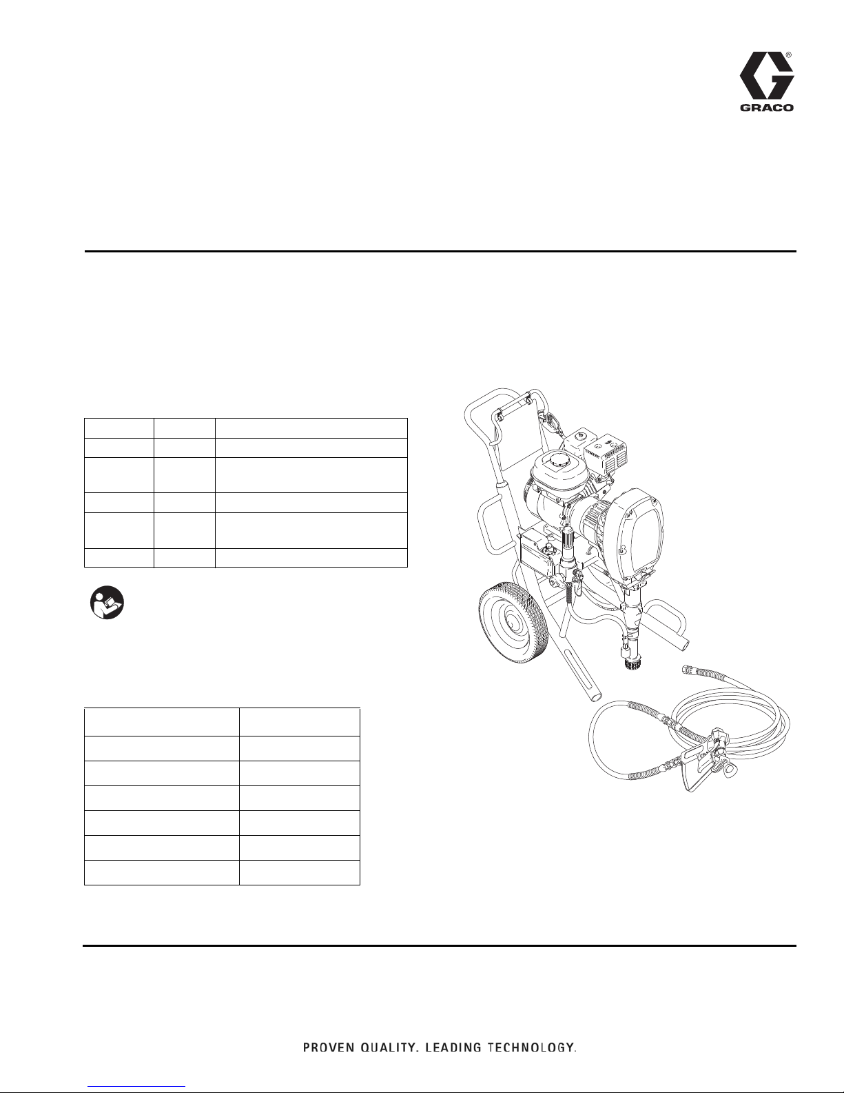
G-Max
7900 Airless
Paint Sprayer
For Portable Airless Spraying of Architectural Coatings and Paints.
3300 psi (227 bar, 22.7 MPa) Maximum Working Pressure
Models
NOTE: All models are not available in all countries.
Model Series Description
232630 B Hi-Boy
232631
232632 B Lo-Boy
232633
233008 A Hi-Boy with Gauge Kit
B
B
Hi-Boy with RAC 5 tip, gun
and hose
Lo-Boy with RAC 5 tip, gun
and hose
308870G
EN
Important Safety Instructions
Read all warnings and instructions in this
manual. Save these instructions.
Related Manuals
Manual Manual Number
Operation
Displacement Pump
Spray Gun
Spray Tip
PC Board
Drain Valve Kit
308867
307898
309091
309055
308919
308961
Page 2

Table of Contents
Table of Contents
Warnings . . . . . . . . . . . . . . . . . . . . . . . . . . . . . . . . . 3
Component Identification . . . . . . . . . . . . . . . . . . . . 5
Maintenance . . . . . . . . . . . . . . . . . . . . . . . . . . . . . . . 6
Pressure Relief Procedure . . . . . . . . . . . . . . . . . 6
Troubleshooting . . . . . . . . . . . . . . . . . . . . . . . . . . . 7
Pinion Assembly / Rotor / Field / Shaft / Clutch . 13
Clamp . . . . . . . . . . . . . . . . . . . . . . . . . . . . . . . . . . . 15
Engine . . . . . . . . . . . . . . . . . . . . . . . . . . . . . . . . . . . 16
On / Off Switch . . . . . . . . . . . . . . . . . . . . . . . . . . . . 17
Pressure Control . . . . . . . . . . . . . . . . . . . . . . . . . . 18
Control Board . . . . . . . . . . . . . . . . . . . . . . . . . . 18
Pressure Control Transducer . . . . . . . . . . . . . . 19
Pressure Adjust Potentiometer . . . . . . . . . . . . . 20
Control Board Diagnostics . . . . . . . . . . . . . . . . 21
Displacement Pump . . . . . . . . . . . . . . . . . . . . . . . 22
Pump Pin Clip . . . . . . . . . . . . . . . . . . . . . . . . . . 23
Parts List & Drawing - Pinion Assembly . . . . . . . 24
Parts Drawing - Hi-Boy Sprayer . . . . . . . . . . . . . . 25
Model 232630 and 233008 . . . . . . . . . . . . . . . . 25
Parts List - Hi-Boy Sprayers . . . . . . . . . . . . . . . . . 26
Models 232630, 232631 and 233008* . . . . . . . 26
Parts Drawing - Lo-Boy Sprayer . . . . . . . . . . . . . 28
Model 232632, 232633 . . . . . . . . . . . . . . . . . . . 28
Parts List - Lo-Boy Sprayers . . . . . . . . . . . . . . . . 29
Models 232632, 232633 . . . . . . . . . . . . . . . . . . 29
Model 232630 through 232633 . . . . . . . . . . . . . 31
Parts List - Hi-Boy Sprayers . . . . . . . . . . . . . . . . . 32
Models 232630 through 232633 . . . . . . . . . . . . 32
Parts List - Complete Sprayers . . . . . . . . . . . . . . 33
Models 232631, 232633 . . . . . . . . . . . . . . . . . . 33
Displacement Pump Repair Kit . . . . . . . . . . . . . 33
Danger Labels . . . . . . . . . . . . . . . . . . . . . . . . . . 33
Wiring Diagram . . . . . . . . . . . . . . . . . . . . . . . . . . . 34
Technical Data . . . . . . . . . . . . . . . . . . . . . . . . . . . . 35
Model 232630, 232631, 232008 . . . . . . . . . . . . 35
Model 232632, 232633 . . . . . . . . . . . . . . . . . . . 35
Graco Warranty . . . . . . . . . . . . . . . . . . . . . . . . . . . 36
2 308870G
Page 3
Warnings
Warnings
The following warnings are for the setup, use, grounding, maintenance, and repair of this equipment. The exclamation point symbol alerts you to a general warning and the hazard symbols refer to procedure-specific risks. When
these symbols appear in the body of this manual or on warning labels, refer back to these Warnings. Product-specific
hazard symbols and warnings not covered in this section may appear throughout the body of this manual where
applicable.
WARNING
FIRE AND EXPLOSION HAZARD
Flammable fumes, such as solvent and paint fumes, in work area can ignite or explode. To help prevent
fire and explosion:
• Use equipment only in well ventilated area.
• Do not fill fuel tank while engine is running or hot; shut off engine and let it cool. Fuel is flammable
and can ignite or explode if spilled on hot surface.
• Eliminate all ignition sources; such as pilot lights, cigarettes, portable electric lamps, and plastic drop
cloths (potential static arc).
• Keep work area free of debris, including solvent, rags and gasoline.
• Do not plug or unplug power cords, or turn power or light switches on or off when flammable fumes
are present.
• Ground all equipment in the work area. See Grounding instructions.
• Use only grounded hoses.
• Hold gun firmly to side of grounded pail when triggering into pail. Do not use pail liners unless they
are antistatic or conductive.
• Stop operation immediately if static sparking occurs or you feel a shock. Do not use equipment
until you identify and correct the problem.
• Keep a working fire extinguisher in the work area.
SKIN INJECTION HAZARD
High-pressure spray is able to inject toxins into the body and cause serious bodily injury. In the event
that injection occurs, get immediate surgical treatment.
• Do not aim the gun at, or spray any person or animal.
• Keep hands and other body parts away from the discharge. For example, do not try to stop leaks
with any part of the body.
• Always use the nozzle tip guard. Do not spray without nozzle tip guard in place.
• Use Graco nozzle tips.
• Use caution when cleaning and changing nozzle tips. In the case where the nozzle tip clogs while
spraying, follow the Pressure Relief Procedure for turning off the unit and relieving the pressure
before removing the nozzle tip to clean.
• Do not leave the unit energized or under pressure while unattended. When the unit is not in use, turn
off the unit and follow the Pressure Relief Procedure for turning off the unit.
• Check hoses and parts for signs of damage. Replace any damaged hoses or parts.
• This system is capable of producing 3000 psi (210 bar/21 MPa). Use Graco replacement parts or
accessories that are rated a minimum of 3000 psi (210 bar/21 MPa).
• Always engage the trigger lock when not spraying. Verify the trigger lock is functioning properly.
• Verify that all connections are secure before operating the unit.
• Know how to stop the unit and bleed pressure quickly. Be thoroughly familiar with the controls.
308870G 3
Page 4
Warnings
WARNING
EQUIPMENT MISUSE HAZARD
Misuse can cause death or serious injury.
• Do not operate the unit when fatigued or under the influence of drugs or alcohol.
• Do not exceed the maximum working pressure or temperature rating of the lowest rated system
component. See Technical Data in all equipment manuals.
• Use fluids and solvents that are compatible with equipment wetted parts. See Technical Data in all
equipment manuals. Read fluid and solvent manufacturer’s warnings. For complete information
about your material, request MSDS from distributor or retailer.
• Do not leave the work area while equipment is energized or under pressure. (
• Turn off all equipment and follow the Pressure Relief Procedure when equipment is not in use.
• Check equipment daily. Repair or replace worn or damaged parts immediately with genuine manufacturer’s replacement parts only.
• Do not alter or modify equipment. Alterations or modifications may void agency approvals and create
safety hazards.
• Make sure all equipment is rated and approved for the environment in which you are using it.
• Use equipment only for its intended purpose. Call your distributor for information.
• Route hoses and cables away from traffic areas, sharp edges, moving parts, and hot surfaces.
• Do not kink or over bend hoses or use hoses to pull equipment.
• Keep children and animals away from work area.
• Comply with all applicable safety regulations.
PERSONAL PROTECTIVE EQUIPMENT
Wear appropriate protective equipment when in the work area to help prevent serious injury, including
eye injury, hearing loss, inhalation of toxic fumes, and burns. This protective equipment includes but is
not limited to:
• Protective eyewear, and hearing protection.
• Respirators, protective clothing, and gloves as recommended by the fluid and solvent manufacturer
4 308870G
Page 5
Component Identification
S
U
W
T
X
V
P
A
B
C
E
F
G
H
J
K
202 Main hose
203 Whip end hose
204 Contractor gun with RAC 5
DripLess tip guard and 517 size SwitchTip
203
204
202
M
N
L
Model 232631
R
D
9034B
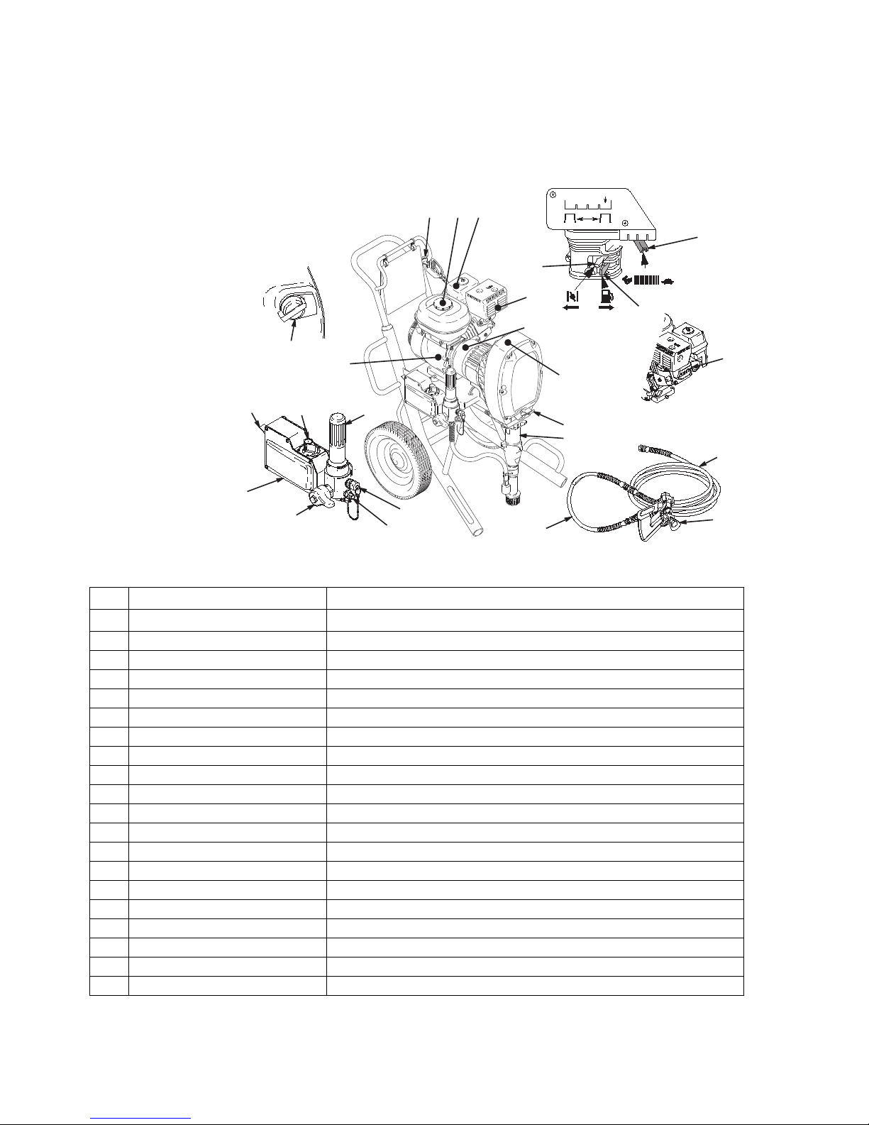
Component Identification
A Pressure Control Switch ON/OFF, enables/disables clutch function and pressure control
B Pressure Adjusting Knob Controls fluid outlet pressure
C Air Cleaner*
D Fuel Tank*
E Muffler*
F Spark Plug Cable*
G Fuel Shutoff Lever*
H Choke*
J Throttle Lever*
K Engine Switch*
L Secondary Fluid Outlet
M Pressure Control
N Primary Fluid Outlet
P Engine*
R Clutch Housing
S Drive Housing
T Displacement Pump
U Fluid Filter
V Grounding Clamp and Wire
W Pail Hanger
X Drain Valve
* For more detailed explanations of these controls, refer to the Honda Engines Owner's Manual; supplied.
Filters air entering the carburetor
Uses 86 octane unleaded gasoline
Reduces noise of internal combustion
Routes electrical current to spark plug
On/off lever to regulate fuel flow from gasoline tank to carburetor
Enriches air/gasoline mixture for cold starting
Adjusts engine speed for large or small orifice spray tips
Enables/disables engine operation
Second hose and spray gun is connected here
Controls clutch cycling to maintain fluid pressure
Hose and spray gun is connected here
4-cycle gasoline engine
Transfers power from engine to drive assembly
Transfers power from clutch to displacement pump
Provides fluid to be sprayed through spray gun
Filters fluid between source and spray gun
Grounds sprayer system
Provides a hanger for paint pail
Relieves fluid pressure when open
308870G 5
Page 6
Maintenance
Maintenance
NOTE: For detailed engine maintenance and specifica-
tions, refer to separate Honda Engines Owner's Manual,
supplied.
Pressure Relief Procedure
Follow the Pressure Relief Procedure whenever
you see this symbol.
This equipment stays pressurized until pressure is
manually relieved. To help prevent serious injury
from pressurized fluid, such as skin injection,
splashing fluid and moving parts, follow the Pressure
Relief Procedure when you stop spraying and before
cleaning, checking, or servicing the equipment.
1. Engage trigger lock.
2. Turn ON/OFF switch to OFF.
3. Move pressure control switch to OFF and turn pressure control knob fully counterclockwise.
4. Unlock trigger safety. Hold metal part of gun firmly
to side of grounded metal pail, and trigger gun to
relieve pressure.
5. Lock gun trigger safety.
6. Open the pressure drain valve. Leave the pressure
drain valve open until you are ready to spray again.
Maintenance Checklist
• DAILY: Check engine oil level and fill as necessary.
• DAILY: Check hose for wear and damage.
• DAILY: Check gun safety for proper operation.
• DAILY: Check pressure drain valve for proper oper-
ation.
• DAILY: Check and fill the gas tank.
AFTER THE FIRST 20 HOURS OF OPERATION:
• Drain engine oil and refill with clean oil. Reference
Honda Engines Owner's Manual for correct oil viscosity.
• WEEKLY: Remove air filter cover and clean element. Replace element, if necessary. If operating in
an unusually dusty environment: check filter daily
and replace, if necessary.
Replacement elements can be purchased from your
local HONDA dealer.
• WEEKLY: Check level of TSL in displacement
pump packing nut. Fill nut, if necessary. Keep TSL
in nut to help prevent fluid buildup on piston rod and
premature wear of packings.
AFTER EACH 100 HOURS OF OPERATION:
• Change engine oil. Reference Honda Engines
Owner's Manual for correct oil viscosity.
7. If you suspect the spray tip or hose is clogged or
that pressure has not been fully relieved after following the steps above, VERY SLOWLY loosen tip
guard retaining nut or hose end coupling to relieve
pressure gradually, then loosen completely. Clear
hose or tip obstruction.
6 308870G
SPARK PLUG:
• Use only BPR6ES (NGK) or W20EPR-U (NIPPONDENSO) plug. Gap plug to 0.028 to 0.031 in. (0.7 to
0.8 mm).
• Use spark plug wrench when installing and removing plug.
Page 7
Troubleshooting
Problem Cause Solution
Engine won't start Engine switch is OFF Turn engine switch ON
Engine is out of gas Refill gas tank. Honda Engines
Owner's Manual.
Engine oil level is low Try to start engine. Replenish oil, if
necessary. Honda Engines Owner's
Manual.
Troubleshooting
Engine operates, but displacement
pump does not operate
Spark plug cable is disconnected or
damaged
Cold engine Use choke
Fuel shutoff lever is OFF Move lever to ON position
Oil is seeping into combustion
chamber
Pressure control switch is OFF Turn pressure control switch ON.
Pressure setting is too low Turn pressure adjusting knob clock-
Fluid filter (318) is dirty Clean filter. Page 31.
Tip or tip filter is clogged Clean tip or tip filter. Manual
Displacement pump piston rod is
stuck due to dried paint
Roller bearings are worn or damaged
Drive housing is worn or damaged Replace drive housing. Page 10.
Connect spark plug cable or replace
spark plug
Remove spark plug. Pull starter
rope 3 or 4 times. Clean or replace
spark plug. Try to start engine.
Keep sprayer upright to avoid oil
seepage.
wise to increase pressure
309091.
Repair pump. Manual 308798.
Replace connecting rod. Page 10.
308870G 7
Page 8

Troubleshooting
Problem Cause Solution
Engine operates, but displacement
pump does not operate (continued)
Electrical power is not energizing
clutch field
Check wiring connections. Page 15.
Reference control board diagnostics. Page 21.
With pressure control switch ON
and pressure turned to MAXIMUM,
use a test light to check for power
between clutch terminals on control
board.
Remove black clutch wires from
control board and measure resistance across wires. At 70_ F, the
resistance must be between 1.7
+0.2W; if not, replace clutch coil
241121.
Have pressure control checked by
authorized Graco dealer.
Clutch is worn or damaged Replace clutch. Page 13.
Pinion assembly is worn or damaged
Repair or replace pinion assembly.
Page 13.
Pump output is low Strainer (31) is clogged Clean strainer
Piston ball (25) is not seating Service piston ball. Manual 308798.
Piston packings are worn or dam-
Replace packings. Manual 308798.
aged
O-ring (227) in displacement pump
Replace o-ring. Manual 308798.
is worn or damaged
Intake valve ball is not seating prop-
Clean intake valve. manual 308798.
erly
Engine speed is too low Increase throttle setting. Manual
308867.
Clutch is worn or damaged Replace clutch. Page 13.
Pressure setting is too low Increase pressure. Manual 308867.
Fluid filter (318), tip filter or tip is
clogged or dirty
Large pressure drop in hose with
heavy materials
Clean filter. Manual 308867 or
309091.
Use larger diameter hose and/or
reduce overall length of hose. Use
of more than 100 ft of 1/4 in. hose
significantly reduces performance of
sprayer. Use 3/8 in. hose for optimum performance (50 ft minimum).
8 308870G
Page 9

Problem Cause Solution
Troubleshooting
Excessive paint leakage into throat
packing nut
Throat packing nut is loose Remove throat packing nut spacer.
Tighten throat packing nut just
enough to stop leakage.
Throat packings are worn or dam-
Replace packings. Manual 308798.
aged
Displacement rod is worn or dam-
Replace rod. Manual 308798.
aged
Fluid is spitting from gun Air in pump or hose Check and tighten all fluid connec-
tions. Reprime pump. Manual
308867.
Tip is partially clogged Clear tip. Manual 309091.
Fluid supply is low or empty Refill fluid supply. Prime pump.
Manual 308867. Check fluid supply
often to prevent running pump dry.
Pump is difficult to prime Air in pump or hose Check and tighten all fluid connec-
tions.
Reduce engine speed and cycle
pump as slowly as possible during
priming.
Intake valve is leaking Clean intake valve. Be sure ball
seat is not nicked or worn and that
ball seats well. Reassemble valve.
Pump packings are worn Replace pump packings. Manual
308798.
Paint is too thick Thin the paint according to the sup-
plier's recommendations.
Engine speed is too high Decrease throttle setting before
priming pump. Manual 308867.
Clutch squeaks each time clutch
engages
Clutch surfaces are not matched to
each other when new and may
cause noise
Clutch surfaces need to wear into
each other. Noise will dissipate after
a day of run time.
Engine stalls Engine speed is to slow - Increase throttle setting.
- Adjust engine speed at no load to
3750 - 3850 rpm
Fluid filter is clogged Relieve pressure and clean filter
Too much pump friction (new pump) Reduce pressure to 3000 psi (20.68
MPa, 206.8 bar) until pump wears in
Spark plug wire is loose Reconnect wire
308870G 9
Page 10
Rollers
9033A
10
9
97
98
20
9
99
24
20
9
99
9
10
20h
20g
18
82
83
B
1
1
Apply remaining grease to these areas
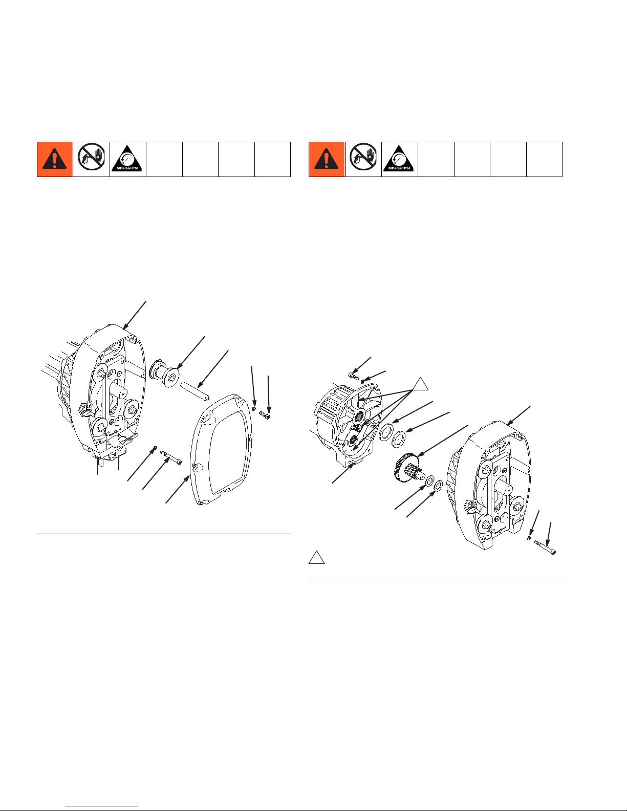
Rollers
Removal
1. Relieve pressure, page 6.
2. Remove six cap screws (10) lock washers (9) and
cover assembly (24) (F
NOTE: A screw driver may be needed to pry off
cover assembly.
IG. 1).
Drive Housing
Removal
1. Relieve pressure, page 6.
2. Remove six cap screws (10) lock washers (9) and
cover assembly (24) (F
3. Remove two screws (99) and washers (9).
4. Remove four cap screws (10) lock washers (9) from
drive housing (20).
5. Lightly tap around drive housing (20) to loosen drive
housing. Pull drive housing straight off pinion housing. Be prepared to support gear cluster (18), which
may also come out.
IG. 1).
FIG. 1
3. Remove dowel pins (97) and rollers (98).
Installation
1. Install rollers (98) and dowel pins (97).
2. Install cover assembly (24) with six lock washers (9)
and cap screws (10).
10 308870G
FIG. 2
Page 11
Rollers
222
33
Installation
1. Liberally apply bearing grease (supplied with
replacement gear cluster) to gear cluster (18),
washers (82) and (83) (F
areas called out by note 1. Use full 0.68 pint (0.32
liter) of grease for GMax 7900.
2. Place bronze colored washer (83) and silver colored
washer (82) (F
IG. 2, page 10) onto drive housing
(20). Install gear cluster (18) through washers (83)
and (82).
3. Place bronze colored washer (20g) and silver colored washer (20h) on shaft protruding from large
shaft of drive housing (20) (F
gears and push new drive housing straight onto pinion housing and locating pins (B).
4. Install two washers (9) and screws (99) (F
page 10).
5. Install four lock washers (9) and cap screws (10)
into drive housing (20) (F
6. Install cover assembly (24) with six lock washers (9)
and cap screws (10) (F
IG. 2, page 10) and to
IG. 2, page 10). Align
IG. 2,
IG. 2, page 10).
IG. 2, page 10).
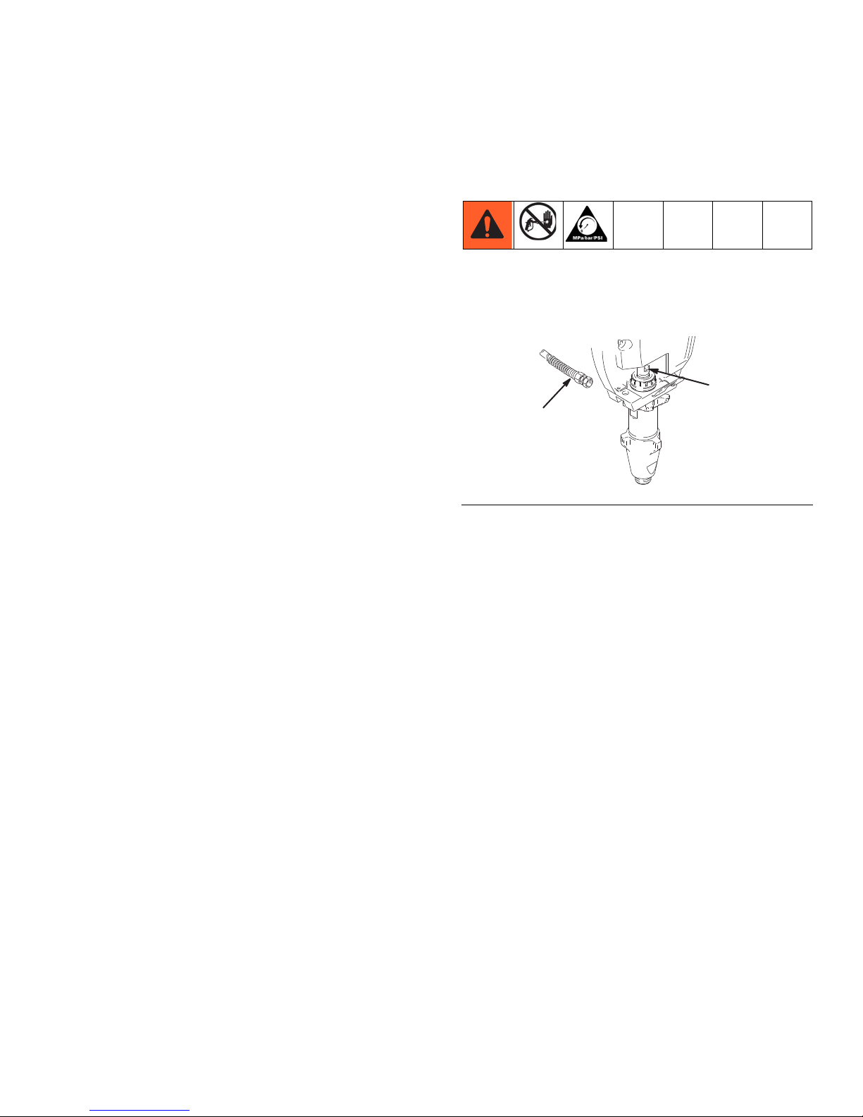
Cam Follower Bearings
Removal
1. Relieve pressure, page 6.
2. Cycle pump piston rod (222) to lowest position (F
3). Turn engine off.
FIG. 3
NOTE: All Steps refer to F
IG. 4.
IG.
3. Remove six cap screws (10), lock washers (9) and
cover assembly (24) (F
IG. 4, page 12).
NOTE: A screw driver may be needed to pry off
cover assembly.
4. Remove four dowel pins (97) and rollers (98) (F
IG.
4, page 12).
5. From front, drive out pump pin (101) with a screw
driver (F
6. Remove two retainer rings (20d) (F
7. Remove cam follower plate (20b) (F
IG. 4, page 12).
IG. 4, page 12).
IG. 4. page 12).
NOTE: Two 1/2 in. x 13 bolts may be needed to
remove cam follower plates.
8. Remove two cam follower bearings (20c) (F
IG. 4,
page 12).
308870G 11
Page 12

Rollers
9047A
101
24
10
9
97
98
20c
20
20b
20d
20a
FIG. 4
Installation
NOTE: All Steps refer to FIG. 4.
1. Install two cam follower bearings (20c).
2. Install cam follower plate (20b).
3. Install two retainer rings (20d).
4. Drive in pump pin (101) until it engages with pump
pin retaining clip (20a).
5. Install four rollers (98) and dowel pin (97).
6. Install cover assembly (24) with six lock washers (9)
and cap screws (10).
12 308870G
Page 13

Pinion Assembly / Rotor / Field / Shaft / Clutch
9027A
X
Bottom View
26
17
26
17
9029A
19
E
72
17
9030
19e
19d
16
17
4a
9028A
Pinion Assembly / Rotor / Field / Shaft / Clutch
Removal
If pinion assembly (19) is not removed from clutch housing (5), do 1. through 4. Otherwise, start at 5.
1. Relieve pressure, page 6.
2. Disconnect field cable (X) from pressure control and
engine lead (F
IG. 5).
FIG. 7
6. Remove retaining ring (19e) (FIG. 8).
FIG. 5
3. Remove five screws (26) and lock washers (17) and
pinion assembly (19) (F
IG. 6).
7. Tap pinion shaft (19d) out with plastic mallet (F
8).
FIG. 8
8. Use an impact wrench or wedge something
between armature (4a) and clutch housing to hold
engine shaft during removal (F
IG. 9).
9. Remove four screws (16) and lock washers (17)
(F
IG. 9).
10. Remove armature (4a) (F
IG. 9).
IG.
FIG. 6
4. Place pinion assembly (19) on bench with rotor side
up.
5. Remove four screws (72) and lock washers (17).
Install two screws in threaded holes (E) in rotor.
Alternately tighten screws until rotor comes off (F
7).
308870G 13
IG.
FIG. 9
Page 14

Pinion Assembly / Rotor / Field / Shaft / Clutch
4a
87
0.12 +.01 in. (3.0 +.25 mm)
19e
19d
E
72
17
17
26
17
9029A
19
9027A
X
Bottom View
Installation
1. Lay two stacks of two dimes on smooth bench surface.
2. Lay armature (4a) on two stacks of dimes (F
3. Press center of clutch down on bench surface.
FIG. 10
4. Install armature (4a) on engine drive shaft.
5. Install four screws (16) and lock washers (17) with
torque of 125 in-lb (14 N.m).
6. Tap pinion shaft (19d) in with plastic mallet (F
11).
IG. 10).
IG.
®1
9. Apply Locktite
and lock washers (17) (F
to screws. Install four screws (16)
IG. 13). Alternately torque
screws to 125 in-lb (14 N.m) until rotor is secure.
Use threaded holes to hold rotor.
FIG. 13
10. Install pinion assembly (19) with five screws (10)
and lock washers (9) (F
IG. 13).
11. Connect field cable (X) to pressure control and
engine lead (F
IG. 14).
FIG. 11
7. Install retaining ring (19e) with beveled side facing
field.
8. Place pinion assembly on bench with rotor side up
(F
IG. 12).
FIG. 12
14 308870G
FIG. 14
1.Locktite® is a registered trademark of Henkel.
Page 15

Clamp
16
5
B
03483
1
3
2
Face of clutch housing
1.812 +.010 in. (46.02 +.25 mm)
Torque to 125 +.10 in-lb (14 +1.1 Nm)
1
2
3
7
8
A
4
Chamfer this side
4
75
77
5
7
15
D
90
Clamp
Removal
NOTE: All Steps refer to FIG. 15.
Clutch Housing
Removal
NOTE: All Steps refer to FIG. 16.
FIG. 16
1. Remove four cap screws (75) and lock washers (77)
which hold clutch housing (5) to engine.\
FIG. 15
1. Loosen two screws (16) on clamp (8).
2. Push screwdriver into slot in clamp (8) and remove
clamp.
Installation
NOTE: All Steps refer to FIG. 15.
1. Install engine shaft key (7).
2. Tap clamp (8) on engine shaft (A) with plastic mallet.
3. Press clamp (8) onto engine shaft (A). Maintain
dimension shown note 2 in Fig. 12. Chamfer side
must face engine.
Check dimension: Place rigid, straight steel bar (B)
across face of clutch housing (5). Use accurate
measuring device to measure distance between bar
and face of clamp. Adjust clamp as necessary.
Torque two screws (16) to 125 +10 in-lb (14 +1.1
N.m).
2. Remove screw (15) from under mounting plate (D).
3. Remove engine key (7).
4. Pull off clutch housing (5)
Installation
NOTE: All Steps refer to FIG. 16.
1. Push on clutch housing (5).
2. Install four cap screws (75) and lock washers (77)
and secure clutch housing (5) to engine. Torque to
200 in-lb (22.6 N.m).
3. Install cap screw (15) from beneath mounting plate
(D). Torque to 26 ft-lb (35.2 N.m).
308870G 15
Page 16

Engine
Green
1
2
To the field
To the engine
1
2
71
87
2
71
70
90
Engine
Removal
1. Remove Pinion Assembly/Rotor/Field/Pinion/Clutch,
Clamp and Clutch Housing. See instructions beginning on pages 13.
2. Disconnect all necessary wiring (F
IG. 17).
Installation
FIG. 17
3. Remove two lock nuts (71) and screws (70) from
base of engine (F
IG. 17).
4. Lift engine carefully and place on work bench.
NOTE: All service to the engine must be performed by
an authorized HONDA dealer.
FIG. 18
1. Lift engine carefully and place on cart (FIG. 18).
2. Install two screws (70) in base of engine and secure
with lock nuts (71) (F
IG. 18). Torque to 200 in-lb
(22.6 N.m).
3. Connect all necessary wiring (F
IG. 17).
4. Install Pinion Assembly/Rotor/Field/Pinion/Clutch,
Clamp and Clutch Housing, as instructed on page
14.
16 308870G
Page 17

On / Off Switch
322
307
A309
302
303
E
D
313
310
318z
318aa
318a
1
Locate switch terminals as shown
1
315 319
NOTE: All Steps refer to FIG. 19.
On / Off Switch
FIG. 19
Removal
1. Relieve pressure, page 6.
2. Remove five screws (307) and cover (322).
3. Disconnect two wires (A) from ON/OFF switch
(309).
4. Press in on two retaining tabs on each side of
ON/OFF switch (309) and remove switch.
Installation
1. Install new ON/OFF switch (309) so tabs of switch
snap into place on inside of pressure control housing.
2. Connect two wires (A) to ON/OFF switch.
3. Install pressure control cover (322) with five screws
(307).
308870G 17
Page 18

Pressure Control
Green
Violet
Pressure
transducer
Potentiometer
Red (+)
Black
Red
309
(Ref)
304
(Ref)
318z
(Ref)
310
(Ref)
302
(Ref)
D
E
A
318aa
(Ref)
Pressure Control
Control Board
NOTE: All Steps refer to FIG. 20.
FIG. 20
Removal
1. Relieve pressure, page 6.
2. Remove five screws (307) and cover (322).
3. Disconnect at control board (302):
• Four clutch leads: two violet and two black.
• Lead (D) from potentiometer.
• Lead (E) from transducer.
• Two red leads (A) to ON/OFF switch (309).
4. Remove five screws (303), green ground wire and
control board (302).
Installation
When installing replacement control board, follow
instructions with control board to set model type.
1. Install green ground wire and control board (302)
with five screws (303).
2. Connect to control board (302):
• Two red leads (A) to ON/OFF switch (309).
• Lead (E) to transducer.
• Lead (D) to potentiometer.
• Four clutch leads: two violet and two black.
3. Fig. 16. Install cover (322) with five screws (307).
18 308870G
Page 19

Pressure Control Transducer
322
307
A309
302
303
E
D
313
310
318z
318aa
318a
1
Locate switch terminals as shown
1
315 319
NOTE: All Steps refer to FIG. 21.
Pressure Control
FIG. 21
Removal
1. Relieve pressure, page 6.
2. Remove five screws (307) and cover (322).
3. Disconnect lead (E) from control board (302).
4. Remove three screws (319) and fluid filter (318)
from control plate (301). Carefully pull transducer
connector through rubber grommet (315).
5. Remove pressure control transducer (318z) and
packing o-ring (318aa) from filter housing (318a).
Installation
1. Install packing o-ring (318aa) and pressure control
transducer (318z) in filter housing (318a). Torque to
30-35 ft-lb.
2. Carefully feed transducer connector through rubber
grommet (315). Install fluid filter (318) on control
plate (301) with three screws (319).
3. Connect lead (E) to motor control board (302).
4. Install cover (322) with five screws (307).
308870G 19
Page 20

Pressure Control
322
307
A309
302
303
E
D
313
310
318z
318aa
318a
1
Locate switch terminals as shown
1
315 319
Pressure Adjust Potentiometer
NOTE: All Steps refer to FIG. 22.
FIG. 22
Removal
1. Relieve pressure, page 6.
2. Remove five screws (307) and cover (322).
3. Disconnect lead (D) from control board (302).
4. Loosen set screws on potentiometer knob (313) and
remove knob, shaft nut, lockwasher (310) and pressure adjust potentiometer (310).
5. Remove seal (311) from potentiometer (310)
Installation
1. Install seal (311) on potentiometer (310).
2. Install pressure adjust potentiometer (310), shaft
nut, lock washer (310) and potentiometer knob
(313).
a. Turn potentiometer shaft (310) clockwise to
internal stop. Assemble potentiometer knob
(313) to strike pin on plate (312).
b. After adjustment of step a., tighten both set
screws in knob 1/4 to 3/8 turn after contact with
shaft.
3. Connect lead (D) to control board (302).
4. Install cover (322) with five screws (307).
20 308870G
Page 21

Control Board Diagnostics
Pressure Control
1. Remove five screws (307) and cover (322) (FIG. 22).
2. Start sprayer.
LED Blinks Sprayer Operation Indicates What to do
Two times
repeatedly
Three times
repeatedly
Four times
repeatedly
Five times
repeatedly
Sprayer shuts down and LED
continues to blink two times
repeatedly
Sprayer shuts down and LED
continues to blink three times
repeatedly
Sprayer shuts down and LED
continues to blink four times
repeatedly
Sprayer shuts down and LED
continues to blink five times
repeatedly
Run away pressure.
Pressure greater than
4500 psi (310 bar, 31
MPa)
Pressure transducer is
faulty or missing
Generator voltage is
low
High clutch current
3. Turn ON/OFF switch ON.
4. Observe LED operation and reference following
table:
1. Check pressure transducer connection at control board.
2. Replace pressure transducer.
3. Replace control board.
1. Check pressure transducer connection at control board.
2. Replace pressure transducer.
3. Replace control board.
1. Increase engine throttle.
2. Check wiring connections.
3. Service Honda engine alternator.
1. Check clutch 5-pin bulkhead connector. Clean contacts.
2. Measure 1.7 +0.2
clutch field at 70°F (21°C).
across
3. Replace clutch field assembly.
Six times
repeatedly
308870G 21
Sprayer shuts down and LED
continues to blink six times
repeatedly
High clutch temperature
1. If clutch is new, let sprayer cool
down and then restart
2. Inspect clutch. Replace clutch if
there is excessive wear.
3. Remove pump pin, separate pinion housing from clutch housing.
Rotate rotor clockwise to check
for excessive drag.
Page 22

Displacement Pump
9024B
222
33
30
9024C
101
20a
Detail A
9019B
9
1.0 in.
9
Displacement Pump
Removal
1. Flush pump.
2. Cycle pump with piston rod (222) in lowest position
(F
IG. 23).
FIG. 23
3. Relieve pressure, page 6.
4. Remove suction tube (30) and hose (33).
5. Use screwdriver to push out pump pin (101) (F
24).
IG.
6. Loosen locknut by hitting firmly with a 20 oz (maximum) hammer (F
IG. 25). Unscrew pump.
FIG. 25
NOTE: See manual 308798 for pump repair instruc-
tions.
Installation
If pin works loose, parts could break off due to force
of pumping action. Parts could project through the air
and result in serious injury or property damage. Make
sure pin (101) and retaining clip (20a) are properly
installed. See Detail A. Fig. 18.
NOTICE
If the pump locknut loosens during operation, the
threads of the bearing housing will be damaged.
Make sure locknut is properly tightened.
FIG. 24
22 308870G
1. Pull piston rod out 1.0 in. Screw in pump until holes
in housing plates and piston rod align (F
IG. 26).
FIG. 26
2. See Detail A (F
IG. 24). Push pin (101) into hole until
retaining clip (20a) snaps over pin.
Page 23

Displacement Pump
90
101
20a
Detail A
9019B
3. Screw jam nut down onto pump until nut stops.
Screw pump up into pump plate until it stops. Back
off pump one full turn and align pump outlet to back.
4. Tighten jam nut by hand, then tap 1/8 to 1/4 turn
with a 20 oz (maximum) hammer to approximately
75 +5 ft-lb (102 Nm) (F
IG. 27).
5. Fill packing nut with Graco TSL until fluid flows onto
the top of seal.
FIG. 27
Pump Pin Clip
Removal
1. Remove pump (28).
2. Remove two bolts (86), washers (25), pump bracket
(85), pail hook (94) and shield (95).
3. Remove clip (20a).
FIG. 28
Installation
1. Install clip (20a) (FIG. 28).
2. Install shield (95), pail hook (94) and pump bracket
(85) with two washers (25) and bolts (86). Torque
bolts to 40 ft-lb (54 NSm).
3. Install pump (28).
308870G 23
Page 24

Parts List & Drawing - Pinion Assembly
10 (Ref)
9 (Ref)
20
20h
20g
18 (Ref)
19a
82 (Ref)
9 (Ref)
99 (Ref)
1
101
83 (Ref)
19d
19e
20a
20d
20c
20b
Parts List & Drawing - Pinion Assembly
Ref No. 19 and 20
Ref No. 19: Pinion Housing Assembly 241116
Ref Part No. Description Qty
19a 241121 PINION HOUSING, coil
19b 105489 PIN
19d 241114 PINION SHAFT
19e 112770 RETAINING RING, large
20 DRIVE HOUSING
21a 194060 RETAINING CLIP, pump pin
Ref Part No. Description Qty
1
2
20b 193656 CAM FOLLOWER PLATE
20c 114691 CAM FOLLOWER BEARING
20d 114828 RETAINER CLIP
20g 114697 WASHER
1
1
20h 114698 WASHER
101 195528 PIN
1
2
2
1
1
1
24 308870G
Page 25

Parts Drawing - Hi-Boy Sprayer
9018D
9027A
5
18
19
10
98
24
97
9
20
2
2
4a
94
101
28
21
25
80
52
86
85
95
16
17
7
8
73
15
17
16
72
17
4b
64
65
10
9
31
26
17
77
103
83
82
20h
2
20g
2
9
99
62
33
34
71
33(Ref)
35
88
4
62
30
105
102
36
2
3
DETAIL A
49
61
70
47
71
43
42
44
41
12
See manual 308798
for the parts.
1
2
3
Label
See page 17 for the parts.
4
See page 22 for the parts.
61
78
78
87
29
93
5
See page 22 for the parts.
64 (Ref)
Ref 11
40
45
37
38
39
Ref 35
DETAIL A
52
104
Model 232630 and 233008
Parts Drawing - Hi-Boy Sprayer
308870G 25
Page 26

Parts List - Hi-Boy Sprayers
Parts List - Hi-Boy Sprayers
Models 232630, 232631 and 233008*
Ref Part No. Description Qty
1 114530 ENGINE
2 113084 RIVET, blind
3 192014 PLATE, indicator
4 241113 CLUTCH, assembly, includes
4a, 4b, 15, 17, 72, 80
4a ARMATURE, clutch, 5 inch
4b ROTOR, 5 inch
5 193531 CLUTCH HOUSING
7 183401 KEY, parallel
8 193680 CLAMP
9 104008 WASHER, spring lock
10 101864 CAPSCREW, socket head,
1/4-20 x 3/4 in.
11 239998 CART HANDLE & HOSE
RACK
12 193682 CAP, end
15 113802 SCREW, flange, hex hd,
3/8-16 x 5/8 in.
16 108803 CAPSCREW, sch, 1/4-2 x 1 in.
17 105510 LOCKWASHER, spring, 1/4 in.
18 241539 GEAR COMBINATION,
include 91 and 92
19 241116 PINION ASSEMBLY; Parts
page 24
20 241536 DRIVE HOUSING, Parts, page
24
21 114967 COUPLING
24 241537 COVER, housing, drive, kit
25 100018 WASHER, lock, spring
26 100644 SCREW, cap
28 240917 DISPLACEMENT PUMP,
Parts manual 308798
29 194438 TUBE, nylon, split
30 244823 TUBE, intake, includes 21
12
10
15
Ref Part No. Description Qty
1
2
1
1
1
1
1
1
1
1
2
1
6
1
1
1
1
1
1
5
1
1
1
31 189920 STRAINER
33 240795 HOSE, coupled
34 193394 NUT, retaining
35 241324 CART FRAME
36 194068 LABEL, identification
37 183350 WASHER, plain
38 110243 RING, retaining
39 108795 SCREW, mch, pn hd, 10-32 x
5/16 in.
40 191084 SLEEVE
41 179811 WHEEL, semi-pneumatic
42 101242 RING, retaining
43 104811 HUBCAP
44 154636 WASHER
45 112827 BUTTON, snap
47 237686 GROUNDING, CLAMP &
WIRE
49 112798 SCREW, hex washer hd, No. 8
x 3/8 in.
52 114984 SCREW, mch, pn hd
56194126 LABEL, warning
61 114678 BUSHING, strain relief
62 162485 NIPPLE, 3/8-18 npsm(m) x 3/8
npt(m)
64 194178 HOSE, drain
65 241718 DEFLECTOR
70 110837 SCREW, flng, hex hd, 5/16-18
x 1-1/2 in.
71 110838 LOCKNUT, heavy, hex hd,
5/16-18
72 101682 SCREW, cap sch
73 108842 SCREW, cap sch
1
1
1
1
1
2
2
4
2
2
2
2
2
2
1
1
2
1
1
3
1
1
2
6
4
4
26 308870G
Page 27

Ref Part No. Description Qty
Parts List - Hi-Boy Sprayers
77 100214 WASHER, lock spring
78 114687 CLIP, retainer
80 HUB, armature
82 114699 WASHER, thrust
83 114672 WASHER, thrust
85 194118 BRACKET, pump
86 110343 SCREW, cap, sch
87 240997 CONUDCTOR, ground
88 110249 ADAPTER, male elbow, 90°
93 108851 WASHER
94 241540 PAIL HOOK Repair Kit,
includes 95
95 195377 GROMMET, pump
96 206994 THROAT SEAL LIQUID; not
shown
97 114695 DOWEL PIN
98 241322 ROLLER, assembly
99 114693 SCREW, cap, sch
101 195523 PIN
102 240987 PLUG, packless 3/8 in.
103194317 LABEL, warning
4
1
1
1
1
1
2
1
1
2
1
1
1
4
4
2
1
1
1
104195119 LABEL, warning; not shown
105 194194 CLIP, spring
1
1
Replacement Danger and Warning labels, tags and
cards are available at no cost.
* Model 233008 includes Gauge Kit 241339.
308870G 27
Page 28

30f
1
5
19
9
98
101
97
99
20
2
2
3
4a
94
25
28
24
80
9
10
43 4142
33
52
12
11
62
DETAIL A
44
3
2
85
16
17
17
26
7
8
73
77
15
71
17
16
72
17
4b
35
30e
30c
30b
30a
49
56
103
82
83
18
20h
2
20g
2
47
70
10
9
86
30aa
30ad
30ae
95
34
30ab
30ac
Ref 11
40
45
37
39
51
Ref 35
DETAIL A
See manual 308798
for the parts.
1
2
3
Label
See page 17 for the parts.
4
See page 22 for the parts.
9
61
78
87
5
93
Bottom View
30b (Ref)
104
30d
33
62
102
4
36
Parts Drawing - Lo-Boy Sprayer
Parts Drawing - Lo-Boy Sprayer
28 308870G
Page 29

Parts List - Lo-Boy Sprayers
Parts List - Lo-Boy Sprayers
Models 232632, 232633
Ref Part No. Description Qty
1 114530 ENGINE
2 113084 RIVET, blind
3 192014 PLATE, indicator
4 241113 CLUTCH, assembly,
includes 4a, 4b, 15, 17, 72,
80
4a ARMATURE, clutch, 5 inch
4b ROTOR, 5 inch
5 193531 CLUTCH HOUSING
7 183401 KEY, parallel
8 193680 CLAMP
9 104008 WASHER, spring lock
10 101864 CAPSCREW, socket head,
1/4-20 x 3/4 in.
11 239998 CART HANDLE & HOSE
RACK
12 193682 CAP, end
15 113802 SCREW, flange, hex hd,
3/8-16 x 5/8 in.
16 108803 CAPSCREW, sch, 1/4-2 x 1
in.
17 105510 LOCKWASHER, spring, 1/4
in.
18 241539 GEAR COMBINATION,
include 91 and 92
19 241116 PINION ASSEMBLY; Parts
page 24
20 241536 DRIVE HOUSING, Parts,
page 24
24 241536 COVER, housing, drive, kit
25 100018 WASHER, lock, spring
26 100644 SCREW, cap
28 240917 DISPLACEMENT PUMP,
Parts manual 308798
29 194438 TUBE, nylon, split
12
10
15
Ref Part No. Description Qty
30 241288 ASSEMBLY, tube suction
1
2
1
1
1
1
1
1
1
1
2
1
6
1
1
1
1
1
5
1
1
30a
30aa
30ab
30ac
30ad
30ae
30b 194180 . HOSE, drain
30c
30d
30e
30f
33 240795 HOSE, coupled
34 193394 NUT, retaining
35 241324 CART FRAME
36 194068 LABEL, identification
37 183350 WASHER, plain
38 110243 RING, retaining
39 108795 SCREW, mch, pn hd, 10-32
40 191043 SLEEVE
41 179811 WHEEL, semi-pneumatic
42 101242 RING, retaining
43 104811 HUBCAP
44 154636 WASHER
45 112827 BUTTON, snap
47 237686 GROUNDING, CLAMP &
49 112798 SCREW, hex washer hd,
52 114984 SCREW, mch, pn hd
56 194126 LABEL, warning
61 114678 BUSHING, strain relief
241269 . TUBE, suction, 30 gallon
(120 L) included 30aa - 3ae
198119 .. SWIVEL, tube inlet
176450 .. GUARD, hose
194307 .. HOSE, fluid
101818 .. CLAMP, hose
192633 .. TUBE, suction
194194 . CLIP, spring
162453 . NIPPLE
241718 . DEFLECTOR
189920 . STRAINER
x 5/16 in.
WIRE
No. 8 x 3/8 in.
1
1
1
1
1
2
1
1
1
1
1
1
1
1
1
1
2
2
4
2
2
2
2
2
2
1
1
2
1
1
308870G 29
Page 30

Parts List - Lo-Boy Sprayers
Ref Part No. Description Qty
62 162485 NIPPLE, 3/8-18 npsm(m) x
3/8 npt(m)
64 194178 HOSE, drain
65 241718 DEFLECTOR
70 110837 SCREW, flng, hex hd,
5/16-18 x 1-1/2 in.
71 110838 LOCKNUT, heavy, hex hd,
5/16-18
72 101682 SCREW, cap sch
73 108842 SCREW, cap sch
77 100214 WASHER, lock spring
78 114687 CLIP, retainer
80 HUB, armature
82 114699 WASHER, thrust
83 114672 WASHER, thrust
85 194118 BRACKET, pump
86 110343 SCREW, cap, sch
87 240997 CONUDCTOR, ground
88 110249 ADAPTER, male elbow, 90°
93 108851 WASHER
94 241540 PAIL HOOK Repair Kit,
includes 95
95 194681 GROMMET, pump
96 206994 THROAT SEAL LIQUID; not
shown
97 114695 DOWEL PIN
98 241322 ROLLER, assembly
99 114693 SCREW, cap, sch
101 195523 PIN
102 240987 PLUG, packless 3/8 in.
103194317 LABEL, warning
3
1
1
2
6
4
4
4
1
1
1
1
1
2
1
1
2
1
1
1
4
4
2
1
1
1
104195119 LABEL, warning; not shown
Replacement Danger and Warning labels, tags and
cards are available at no cost.
30 308870G
1
Page 31

Model 232630 through 232633
Models 232630 through 232633
318k
318j
318l
307
322
305
310
311
306
315
318z
318aa
303
302
309
308
312
310
313
314
304
305
301
307
304
318c
318a
318b
318d
318e
318f
8716A
319
321
320
318n
318m
318h
318g
323
Parts List - Lo-Boy Sprayers
308870G 31
Page 32

Parts List - Hi-Boy Sprayers
Parts List - Hi-Boy Sprayers
Models 232630 through 232633
Ref Part No. Description Qty
301 193653 PLATE, control
302 241093 BOARD, PC
303 111839 SCREW, mch pan, 6-32 x
1/2 in.
304 240776 HARNESS, wiring
305 193497 GASKET, control
306 193652 HOUSING, control box
307 114631 SCREW, mach, pan hd
308 193052 PLATE, instruction
309 114277 SWITCH, rocker (spst)
310 241443 POTENTIOMETER, pres-
sure control
311 193657 GASKET, potentiometer
312 193654 PLATE, instruction
313 114273 KNOB, potentiometer
314 193072 LABEL, control
315 114629 GROMMET, transducer
318 FILTER, fluid
318a 193651 HOUSING, filter
318b 104361 O-RING
318c 186075 SUPPORT, filter
318d 167025 STRAINER, mesh, 60
318e 171941 SPRING, compression
318f 192706 BOWL, filter
318g 193710 SEAL, valve
318h 193709 SEAT, valve
318j 194102 HANDLE, valve
319k 114688 NUT, cap, hex hd
319l 114708 SPING, compression
319m 114797 GASKET
318n 245103* VALVE
10
Ref Part No. Description Qty
318z 240314 TRANSDUCER, pressure
control includes 318aa
1
1
5
1
2
1
1
1
1
1
1
1
1
1
1
1
1
1
1
1
1
1
1
1
1
1
1
1
318aa
319 110997 SCREW, flange, hex
320 114532 TIE, wire, twist
321 189246 LABEL, warning
322 241444 COVER, pressure control
323 193684 LABEL, identification
Replacement Danger and Warning labels, tags and
cards are available at no cost.
* Drain valve replacement kit 245103 included 318g
through 318n.
111457 O-RING
1
1
3
1
1
1
1
32 308870G
Page 33

Parts List - Complete Sprayers
204
203
202
0160
Apply other
language here
90
Parts List - Complete Sprayers
Models 232631, 232633
Includes 201 to 204
Ref. Part No. Description Qty
201 232631 Hi-Boy Sprayer, see Parts list
on page 26
232633 Lo-Boy Sprayer, See Parts list
on page 32
202 240797 HOSE, grounded, nylon, 3/8
in. ID; cpld 3/8 npsm(fbe); 50
foot (15 m); spring guards both
ends
203 238358 HOSE, grounded, nylon; 3/16.
ID; cpld 1/4 npsm(m) x 1/4
npsm(f) swivel; 3 foot (0.9 m);
spring guards both ends
204 220955 CONTRACTOR SPRY GUN,
includes RAC 5
Guard and 517-size
SwitchTip
parts
™
DripLess Tip
™
, see 309091 for
Accessories
Danger Labels
An English language
1
DANGER label is on
your sprayer. If you
1
have painters who do
not read English,
order one of the fol-
1
lowing labels to apply
to your sprayer. The
drawing shows the best placement of these labels for
good visibility.
1
Order the labels from your Graco distributor.
Language Part No.
1
French 194931
Spanish 194932
German 194933
Greek 194934
Korean 194935
English 194317
308870G 33
Displacement Pump Repair Kit
Packing repair kit. - GMax 7900: 240916
Page 34

Wiring Diagram
Green
Violet
Pressure
transducer
Potentiometer
Red (+)
Black
Red
309
(Ref)
304
(Ref)
318z
(Ref)
310
(Ref)
302
(Ref)
D
E
A
318aa
(Ref)
Wiring Diagram
34 308870G
Page 35

Technical Data
Technical Data
Honda GX160 Engine
Power Rating @ 3700 RPM
ANSI 5.5 horsepower
DIN 6270B/DIN 6271
NA 2.9 Kw - 4.0 Ps
NB 3.6 Kw - 4.9 Ps
Maximum working pressure 3300 psi (227 bar, 22.7 MPa)
Noise Level
Sound power 105 dBa per ISO 3744
Sound pressure 96 dBa measured at 3.1 feet (1 m)
Cycle/gallon (liter) 69 (18)
Maximum delivery rating 2.1 gpm (7.9 liter/min)
Maximum tip size 1 gun with 0.046 in. tip
2 guns with 0.033 in. tip
3 gun with 0.026 in. tip
4 guns with 0.022 in. tip
Inlet pain strainer 16 mesh (1190 micron) stainless steel screen, reusable
Outlet paint filter 60 mesh (250 micron) stainless steel screen, reusable
Pump inlets size 3/4 in. npt(m)
Fluid outlet size 1/4 npsm from fluid filter
Wetted parts zinc-plated carbon steel, PTFE, Nylon, polyurethane,
UHMW polyethylene, FKM, acetal, leather, aluminum,
tungsten, carbide, nickel-plated carbon steel, stainless
steel, chrome plating
Dimensions
Model 232630, 232631, 232008
Hi-Boy without hose or gun
Weight (dry without packaging) 175 lb (79.4 kg)
Height 41 in. (104.1 cm)
Length 38 in. (96.5 cm)
Width 22 in. (55.9 cm)
308870G 35
Model 232632, 232633
Lo-Boy Cart without hose or gun
Weight (dry without packaging) 180 lb (82.1 kg)
Height 41 in. (104.1 cm)
Length 38 in. (96.5 cm)
Width 22 in. (55.9 cm)
Page 36

Graco Warranty
Graco warrants all equipment manufactured by Graco and bearing its name to be free from defects in material and workmanship on the date of
sale by an authorized Graco distributor to the original purchaser for use. With the exception of any special, extended, or limited warranty published
by Graco, Graco will, for a period of twelve months from the date of sale, repair or replace any part of the equipment determined by Graco to be
defective. This warranty applies only when the equipment is installed, operated and maintained in accordance with Graco's written recommendations.
This warranty does not cover, and Graco shall not be liable for general wear and tear, or any malfunction, damage or wear caused by faulty installation, misapplication, abrasion, corrosion, inadequate or improper maintenance, negligence, accident, tampering, or substitution of non-Graco
component parts. Nor shall Graco be liable for malfunction, damage or wear caused by the incompatibility of Graco equipment with structures,
accessories, equipment or materials not supplied by Graco, or the improper design, manufacture, installation, operation or maintenance of structures, accessories, equipment or materials not supplied by Graco.
This warranty is conditioned upon the prepaid return of the equipment claimed to be defective to an authorized Graco distributor for verification of
the claimed defect. If the claimed defect is verified, Graco will repair or replace free of charge any defective parts. The equipment will be returned
to the original purchaser transportation prepaid. If inspection of the equipment does not disclose any defect in material or workmanship, repairs
will be made at a reasonable charge, which charges may include the costs of parts, labor, and transportation.
THIS WARRANTY IS EXCLUSIVE, AND IS IN LIEU OF ANY OTHER WARRANTIES, EXPRESS OR IMPLIED, INCLUDING BUT NOT LIMITED TO WARRANTY OF MERCHANTABILITY OR WARRANTY OF FITNESS FOR A PARTICULAR PURPOSE.
Graco's sole obligation and buyer's sole remedy for any breach of warranty shall be as set forth above. The buyer agrees that no other remedy
(including, but not limited to, incidental or consequential damages for lost profits, lost sales, injury to person or property, or any other incidental or
consequential loss) shall be available. Any action for breach of warranty must be brought within two (2) years of the date of sale.
Graco makes no warranty, and disclaims all implied warranties of merchantability and fitness for a particular purpose in connection with accessories, equipment, materials or components sold but not manufactured by Graco. These items sold, but not manufactured by Graco (such as electric
motors, switches, hose, etc.), are subject to the warranty, if any, of their manufacturer. Graco will provide purchaser with reasonable assistance in
making any claim for breach of these warranties.
In no event will Graco be liable for indirect, incidental, special or consequential damages resulting from Graco supplying equipment hereunder, or
the furnishing, performance, or use of any products or other goods sold hereto, whether due to a breach of contract, breach of warranty, the negligence of Graco, or otherwise.
FOR GRACO CANADA CUSTOMERS
The parties acknowledge that they have required that the present document, as well as all documents, notices and legal proceedings entered into,
given or instituted pursuant hereto or relating directly or indirectly hereto, be drawn up in English. Les parties reconnaissent avoir convenu que la
rédaction du présente document sera en Anglais, ainsi que tous documents, avis et procédures judiciaires exécutés, donnés ou intentés à la suite
de ou en rapport, directement ou indirectement, avec les procedures concernées.
ADDITIONAL WARRANTY COVERAGE
Graco does provide extended warranty and wear warranty for products described in the "Graco Contractor Equipment Warranty Program”.
Graco Phone Number
TO PLACE AN ORDER, contact your Graco distributor, or call this number to identify the distributor closest to you: 1-800-690-2894 Toll Free
All written and visual data contained in this document reflects the latest product information available at the time of publication.
Graco reserves the right to make changes at any time without notice.
Original instructions. This manual contains English. MM 308870
For Patent Information see www.graoc.com/patents
Graco Headquarters: Minneapolis
International Offices: Belgium, China, Japan, Korea
GRACO INC. AND SUBSIDIARIES • P.O. BOX 1441 • MINNEAPOLIS MN 55440-1441 • USA
Copyright 1999, Graco Inc. All Graco manufacturing locations are registered to ISO 9001.
www.graco.com
Revised April 2014
 Loading...