

Page 1
Instructions
Conforms to ANSI/UL 73
Certified to CAN/CSA
Std. 22.2 No 68-09
3132066
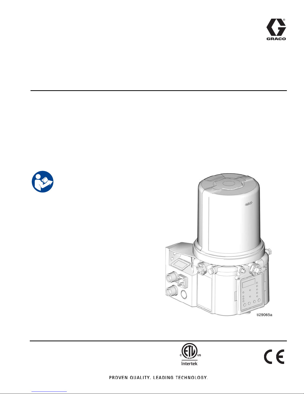
G3 Pro Automatic
332298E
Lubrication Pump
For dispensing of NLGI Grades #000 to #2 greases and oil with at least 40cSt. For
Professional Use Only.
Not approved for use in explosive atmospheres or hazardous locations.
Part Nos., page 3
5100 psi (35.1 MPa, 351.6 bar) Pump Output Pressure
5000 psi (34.4 MPa, 344.7 bar) Fill Inlet Pressure
EN
Important Safety Instructions
Read all warnings and instructions in this
manual. Save all instructions.
Page 2

Table of Contents
Table of Contents
Part / Model Numbers . . . . . . . . . . . . . . . . . . . . . . . 3
2 Liter Models . . . . . . . . . . . . . . . . . . . . . . . . . . . 3
4 Liter Models . . . . . . . . . . . . . . . . . . . . . . . . . . . 3
8 Liter Models . . . . . . . . . . . . . . . . . . . . . . . . . . . 3
12 Liter Models . . . . . . . . . . . . . . . . . . . . . . . . . . 3
16 Liter Models . . . . . . . . . . . . . . . . . . . . . . . . . . 3
Understanding the Model Number . . . . . . . . . . . 4
Warnings . . . . . . . . . . . . . . . . . . . . . . . . . . . . . . . . . 5
Installation . . . . . . . . . . . . . . . . . . . . . . . . . . . . . . . . 7
Typical Installation . . . . . . . . . . . . . . . . . . . . . . . . 8
Typical Installation - With Remote Fill Manifold . . 9
Optional Installation -
Without Remote Fill Manifold . . . . . . . . . . . 10
Choosing an Installation Location . . . . . . . . . . . 11
System Configuration and Wiring . . . . . . . . . . . 12
Setup . . . . . . . . . . . . . . . . . . . . . . . . . . . . . . . . . . . . 17
Connecting to Auxiliary Fittings . . . . . . . . . . . . . 17
Setting Pump Outlet Volume . . . . . . . . . . . . . . . 18
Loading Grease . . . . . . . . . . . . . . . . . . . . . . . . 18
Auto-Fill Shut Off . . . . . . . . . . . . . . . . . . . . . . . . 20
Filling Oil Unit . . . . . . . . . . . . . . . . . . . . . . . . . . 22
Priming . . . . . . . . . . . . . . . . . . . . . . . . . . . . . . . 23
Quick Setup Guide . . . . . . . . . . . . . . . . . . . . . . . . 24
Pro Model Setup . . . . . . . . . . . . . . . . . . . . . . . . . . 25
Control Panel Overview . . . . . . . . . . . . . . . . . . 25
Instructions . . . . . . . . . . . . . . . . . . . . . . . . . . . . 26
Advanced Programming . . . . . . . . . . . . . . . . . . . . 29
Run Mode . . . . . . . . . . . . . . . . . . . . . . . . . . . . . . . . 31
Time Control . . . . . . . . . . . . . . . . . . . . . . . . . . . 31
Alarms . . . . . . . . . . . . . . . . . . . . . . . . . . . . . . . . . . 33
Fault / Warning Scenarios . . . . . . . . . . . . . . . . . 33
Troubleshooting . . . . . . . . . . . . . . . . . . . . . . . . . . . 34
Maintenance . . . . . . . . . . . . . . . . . . . . . . . . . . . . . . 35
Parts - 2 Liter Models . . . . . . . . . . . . . . . . . . . . . . 36
Parts - 4 Liter and Larger Models . . . . . . . . . . . . . 37
Parts . . . . . . . . . . . . . . . . . . . . . . . . . . . . . . . . . . . . 38
Technical Data . . . . . . . . . . . . . . . . . . . . . . . . . . . . 41
Dimensions . . . . . . . . . . . . . . . . . . . . . . . . . . . . 41
Mounting Pattern . . . . . . . . . . . . . . . . . . . . . . . . 42
Notes . . . . . . . . . . . . . . . . . . . . . . . . . . . . . . . . . . . . 43
Graco Standard Warranty . . . . . . . . . . . . . . . . . . . 44
Graco Information . . . . . . . . . . . . . . . . . . . . . . . 44
2 332298E
Page 3

Part / Model Numbers
Part / Model Numbers
The Part Number is a six-digit unique number that is o nly us ed t o orde r t h e G3 Pum p. Directly related to this six digit
Part Number is the configured Graco Model Number. This configured number identifies the distinct features of a specific G3 Pump. To help you understand each component that makes up the Model Number see Understanding Your
Model Number, page 4. The tables below shows the relationship between each Part Number and its related Model
Number.
2 Liter Models
Part
Numbers
96G011 G3-G-24PR-2L0L00-R0C00000
96G012 G3-G-24PR-2LFL00-R0C00000
96G013 G3-G-ACPR-2L0L00-0D000000
96G014 G3-G-ACPR-2LFL00-0D000000
96G027 G3-G-12PR-2L0000-00C00000
96G028 G3-G-24PR-2L0000-00C00000
96G029 G3-G-ACPR-2L0000-0D000000
96G033 G3-G-12PR-2L0L05-00C00000
96G034 G3-G-24PR-2L0L05-00C00000
96G070 G3-A-24PR-2L0L00-R0C00000
96G079 G3-A-ACPR-2L0L00-0D000000
Model Numbers
4 Liter Models
Part
Numbers
96G068 G3-G-24PR-4L0L00-R0C00000
96G071 G3-A-24PR-4L0L00-R0C00000
96G073 G3-G-24PR-4LFL00-R0C00000
96G075 G3-G-ACPR-4L0L00-0D000000
96G080 G3-A-ACPR-4L0L00-0D000000
96G082 G3-G-ACPR-4LFL00-0D000000
96G135 G3-G-12PR-4L0000-00C00000
96G137 G3-G-24PR-4L0000-00C00000
96G139 G3-G-ACPR-4L0000-0D000000
96G147 G3-G-12PR-4L0L05-00C00000
96G149 G3-G-24PR-4L0L05-00C00000
96G211 G3-G-24PR-4LAL05-00C00000
Model Numbers
8 Liter Models
Part
Numbers
96G069 G3-G-24PR-8L0L00-R0C00000
96G072 G3-A-24PR-8L0L00-R0C00000
96G076 G3-G-ACPR-8L0L00-0D000000
96G081 G3-A-ACPR-8L0L00-0D000000
96G136 G3-G-12PR-8L0000-00C00000
96G138 G3-G-24PR-8L0000-00C00000
96G140 G3-G-ACPR-8L0000-0D000000
96G148 G3-G-12PR-8L0L05-00C00000
96G150 G3-G-24PR-8L0L05-00C00000
96G208 G3-G-ACPR-8LAL00-0D00000
96G214 G3-G-24PR-8LAL05-00C00000
Model Numbers
12 Liter Models
Part
Numbers
96G077 G3-G-ACPR-120L00-0D000000
96G163 G3-G-24PR-120L05-00C00000
Model Numbers
16 Liter Models
Part
Numbers
96G078 G3-G-ACPR-160L00-0D000000
96G167 G3-G-24PR-160L05-00C00000
Model Numbers
332298E 3
Page 4
Part / Model Numbers
k
m
n
p
h
j
i
g
Understanding the Model Number
Use the Code Sample provided below to identify each component’s location in the Model Number. The options for
each component that make up the code are provided on the lists below.
NOTE: Some pump configur ations are n ot a v ailable. Contact Graco Cu stomer Service or your local Gr aco distrib utor
for assistance.
G3 -G- PR 0 00 0
Code Sample: a a b b - c c d e f f - g h i j k m n p
G3 - G = Identifies pump as being a G3; G = Grease
G3 - A = Identifies pump as being a G3; A = Oil
Code aa: Power Source
• 12 = 12 Volts DC
• 24 = 24 Volts DC
• AC = 100 - 240 Volts AC
Code bb: Operation Control
• PR = Pro (Timer) Control
Code cc: Reservoir Capacity (Liters)
• 2L = 2 Liters
• 4L = 4 Liters
• 8L = 8 Liters
• 12 = 12 Liters
• 16 = 16 Liters
Code d: Follower Plate Installed
• F = Follower Plate Installed
• 0 = No Follower Plate
• A - Auto-Fill Shut Off
Code e: Low Level Option
• L = Low Level with Controller
• 0 = No Low Level monitoring
Code ff: Options
• 00 = No Options
• 05 = 5 Pin CPC power cable
• 07 = No Power Cord
Code g, h, i, j, k, m, n, p
NOTE: Codes g - p relate to a specific location on the
G3 pump. See F
•C = CPC
•D = DIN
• R = Remote Manual Run
• 0 = Not populated
IG. 1 for these locations.
FIG. 1
4 332298E
Page 5
Warnings
Warnings
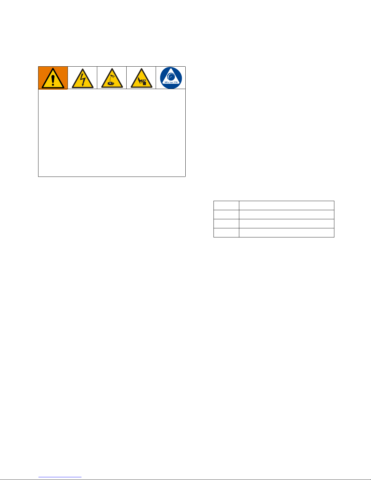
The following warnings are for the setup, use, grounding, maintenance, and repair of t his equipment. The exclamation point symbol alerts you to a general warning and the hazard symbols refer to procedure-specific risks. When
these symbols appear in the body of this manual or on warning labels, ref er bac k to these W arnings. Produ ct-specific
hazard symbols and warnings not covered in this section may appear throughout the body of this manual where
applicable.
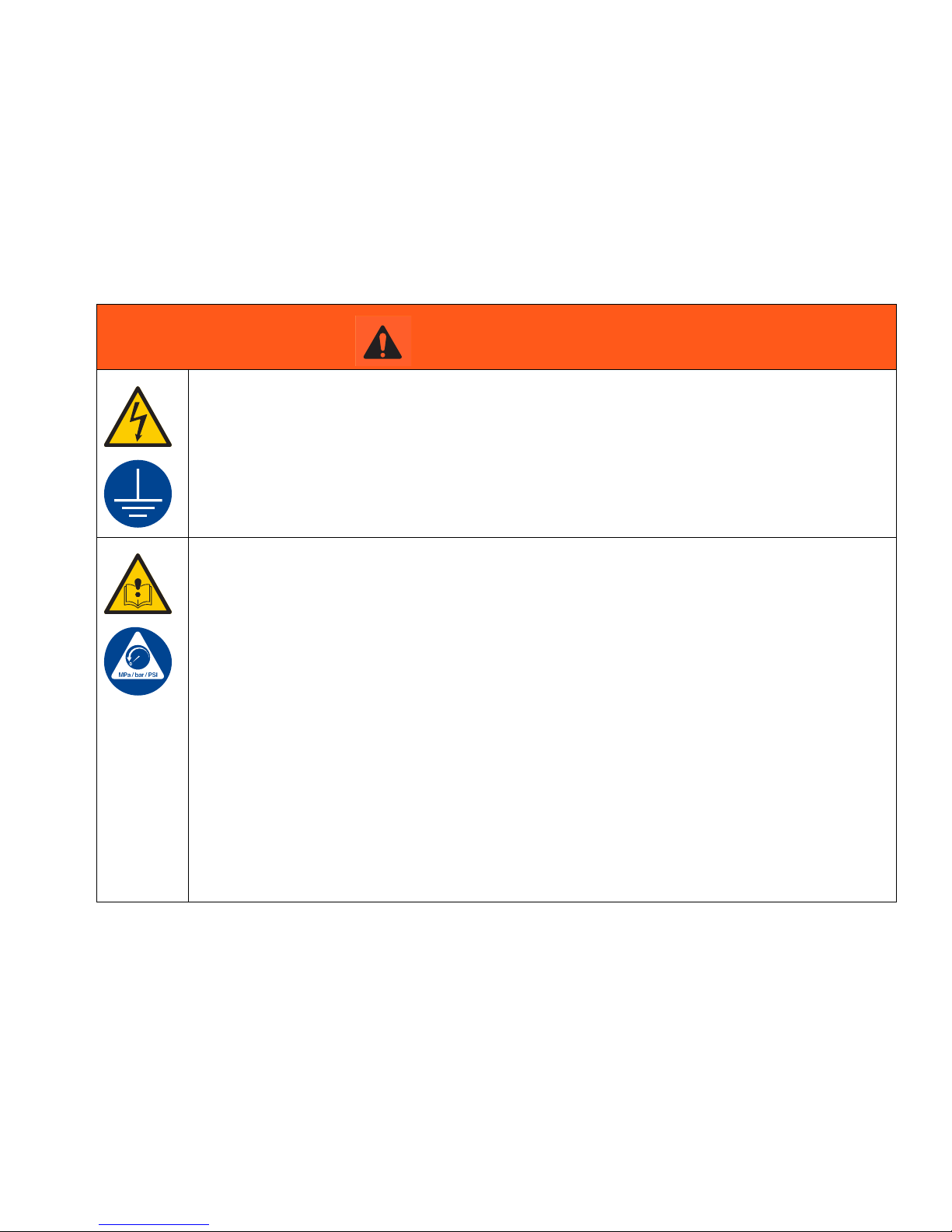
WARNING
ELECTRIC SHOCK HAZARD
This equipment must be grounded. Improper grounding, setup, or usage of the system can cause
electric shock.
• T urn off and disconnect power at main switch before disconnecting any cables and before servicing
or installing equipment.
• Connect only to grounded power source.
• All electrical wiring must be done by a qualified electrician and comply with all local codes and regulations.
EQUIPMENT MISUSE HAZARD
Misuse can cause death or serious injury.
• Do not operate the unit when fatigued or under the influence of drugs or alcohol.
• Do not exceed the maximum working pressure or temperature rating of the lowest rated system
component. See Technical Data in all equipment manuals.
• Use fluids and solvents that are compa tible with equipment wetted parts. See T echnical Data in all
equipment manuals. Read fluid and solvent manufacturer’s warnings. For complete information
about your material, request MSDS from distributor or retailer.
• Turn off all equipment and follow the Pressure Relief Procedure when equipment is not in use.
• Check equipment daily. Repair or replace worn or damaged parts immediately with genuine manufacturer’s replacement parts only.
• Do not alter or modify equipment. Alterations or mo difications ma y void agency a pprov als and create safety hazards.
• Make sure all equipment is rated and approved for the environment in which you are using it.
• Use equipment only for its intended purpose. Call your distributor for info rmation.
• Route hoses and cables away from traffic areas, sharp edges, moving parts, and hot surfaces.
• Do not kink or over bend hoses or use hoses to pull equipment.
• Keep children and animals away from work area.
• Comply with all applicable safety regulations.
332298E 5
Page 6
Warnings
WARNING
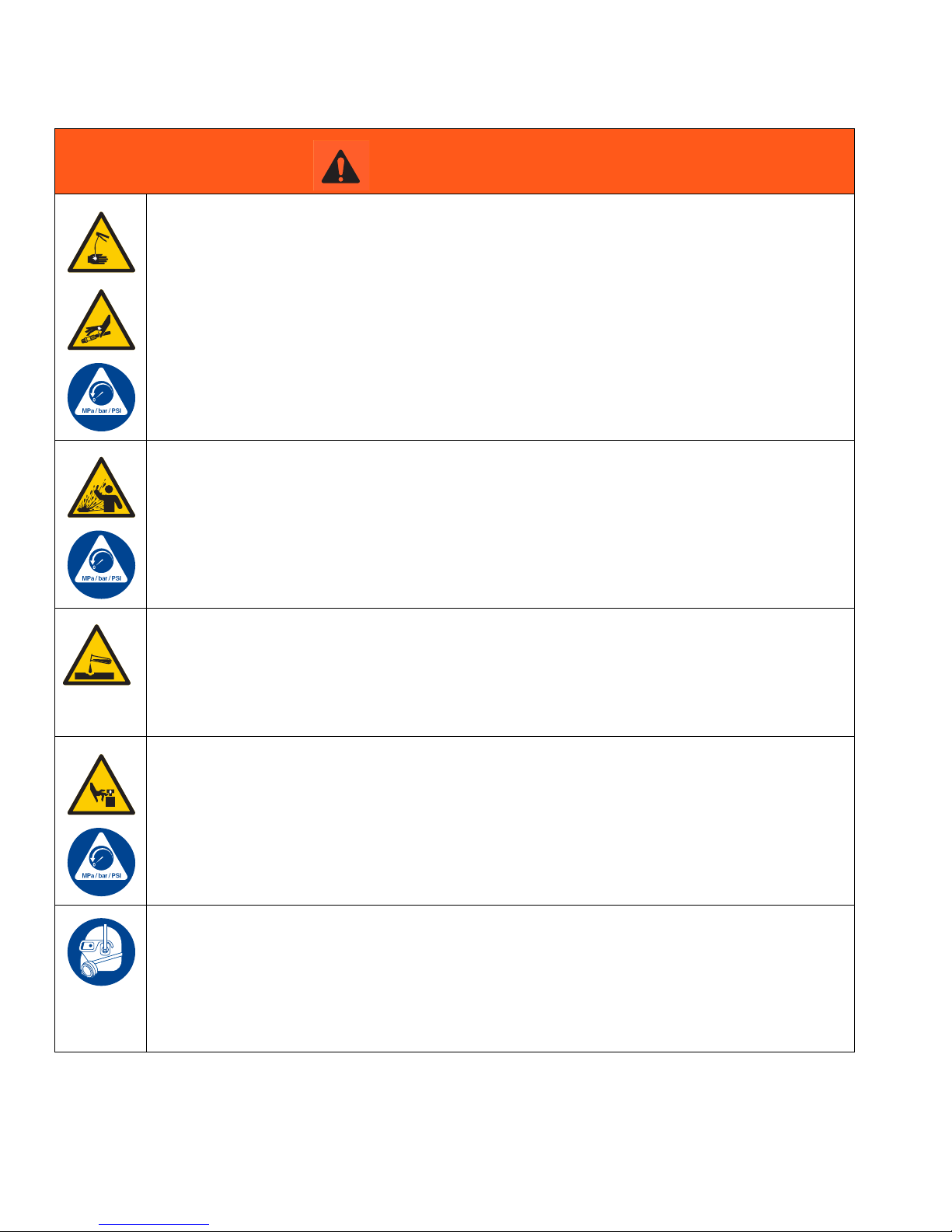
SKIN INJECTION HAZARD
High-pressure fluid from dispensing device, hose leaks, or ruptured components will pierce skin. This
may look like just a cut, but it is a serious injury that can result in amputation. Get immediate surgi-
cal treatment.
• Do not point dispensing device at anyone or at any part of the body.
• Do not put your hand over the fluid outlet.
• Do not stop or deflect leaks with your hand, body, glove, or rag.
• Follow the Pressure Relief Pr ocedure when y ou stop dispensing and bef ore clean ing, checking ,
or servicing equipment.
• Tighten all fluid connections before operating the equipment.
• Check hoses and couplings daily. Replace worn or damaged parts immediately.
PRESSURIZED EQUIPMENT HAZARD
Over-pressurization can result in equipment rupture and serious injury.
• A pressure relief valve is required at each pump outlet.
• Follow Pressure Relief Procedure in this manual before servicing.
PLASTIC PARTS CLEANING SOLVENT HAZARD
Many solvents can deg rade plastic parts and cause them to fail, which could cause serious injury or
property damage.
• Use only compatible water-based solv ents to clean plastic structural or pressure-containing parts.
• See Technical Data in this and all other equipment instruction manuals. Read fluid and solvent
manufacturer’s MSDSs and recommendations.
MOVING PARTS HAZARD
Moving parts can pinch, cut or amputate fingers and other body parts.
• Keep clear of moving parts.
• Do not operate equipment with protective guards or cov ers removed.
• Pressurized equipment can start without warning. Before checking, moving, or servicing equipment, follow the Pressure Relief Procedure and disconnect all power sources.
PERSONAL PROTECTIVE EQUIPMENT
Wear appropriate protective equipment when in the work area to help prevent serious injury, including eye injury, hearing loss, inhalation of toxic fumes, and burns. This protective equipment includes
but is not limited to:
• Protective eyewear, and hearing protection.
• Respirators, protective clothing, and gloves as recommended by the fluid and solvent manuf acturer
6 332298E
Page 7
Installation
A
D
H
I
B
E
F
J
G3-G-24PR-2LFL00-R0C00000
Grease Models with Follower
Plate
L
M
96GXXX
Oil Models
N
Grease Models
R
Auto-Fill Shut Off Models
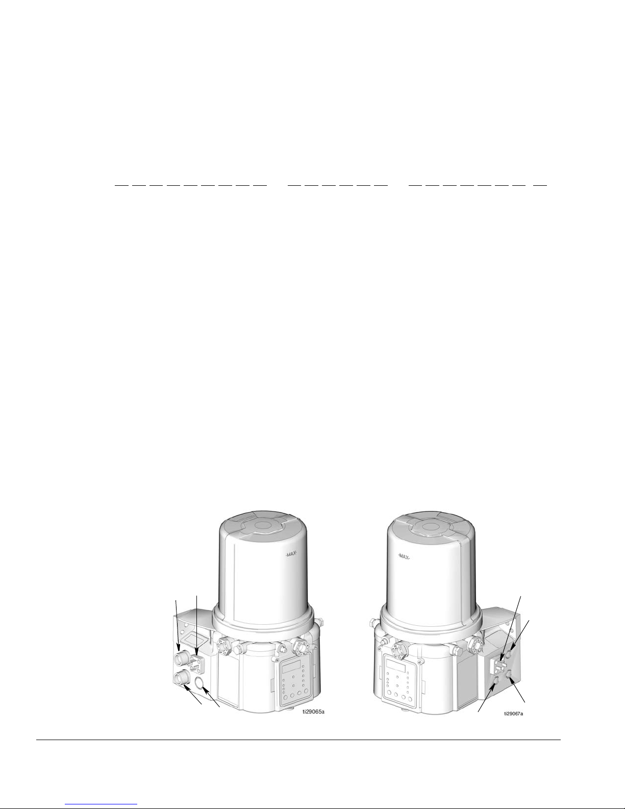
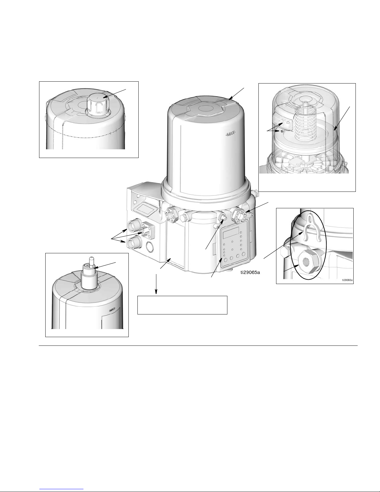
Component Identification
Installation
FIG. 2:
Key:
A Reservoir
B Pump Element (1 included. Can accommodate 3 total)
C Pressure Relief Valve (Not included / required for each
outlet - Available from Graco. See Parts, page 40.)
D Zerk Inlet Fill Fitting (1 included / grease models only)
E Pump Outlet Plug (2 included)
F Volume Control Spacers (2 included. More spacers = less
G Fuse (DC models only - Not included, not shown.
H Control Panel
I Power / Sensor Panel (both sides; only one side shown)
J Part Number / Model Number example only shown, (see
K Power Cord (DIN shown)
output volume per stroke) (also see F
Availab le from Graco. See Parts, page 39.)
IG. 15, page 18)
pages 4, Understanding the Model Number, for details)
L Follower Plate (grease models only / not availabl e on al l
M Vent Hole for Follower Plate (grease models only / not
N Fill cap (oil models only)
R Auto-Fill Shut Off
grease models)
available on all grease models)
332298E 7
Page 8
Installation
A
B
C
D
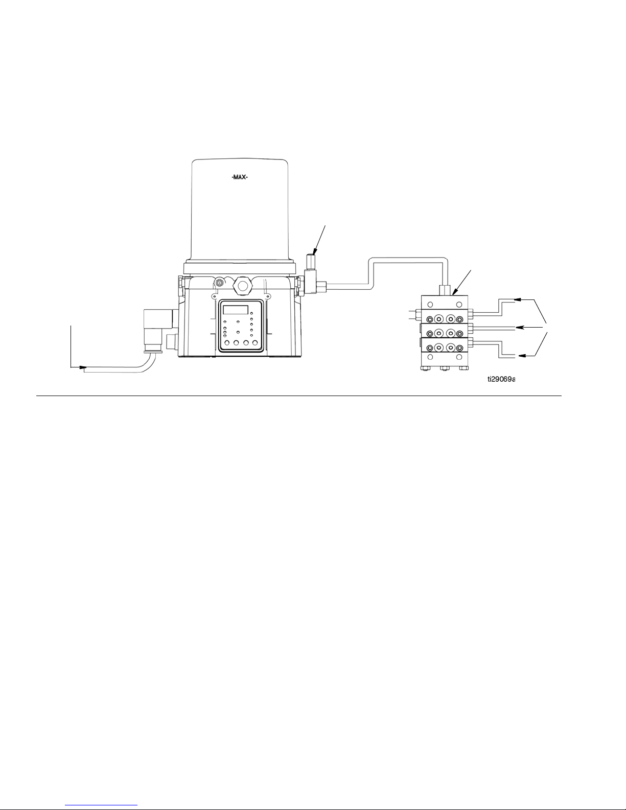
Typical Installation
Series Progressive Divider Valve Installations
FIG. 3
A Connected to fused power source
B Pressure relief valve (Not included/required for each outlet
- user supplied. See Parts, page 40)
C Series progressive divider valves (Divider Installations)
D To lube points
8 332298E
Page 9
Installation
E
D
C
F
P
N
K
H
J
M
L
A
R
Q
B
S
T
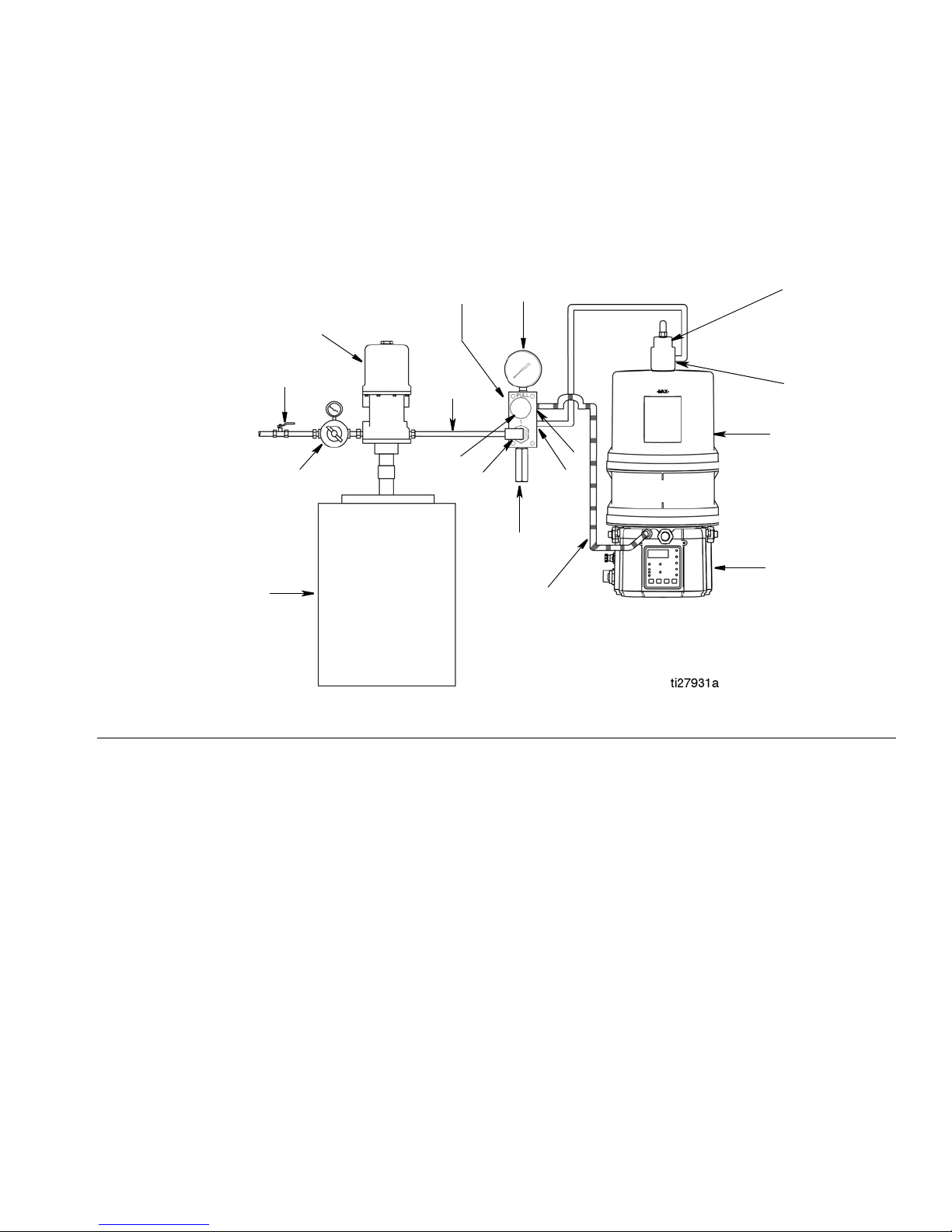
Typical Installation - With Remote Fill Manifold
The installation shown is only a guide for selecting and installing system components. Contact your Graco distributor
for assistance in planning a system to suit your needs.
FIG. 4
Key:
AG3 Pump
B Auto-Fill Shut Off Valve
C Auto-Fill Inlet
D G3 Reservoir
E Remote Fill Reservoir
F Remote Fill Pump
G Supply Hose (user supplied)
H Air Supply to Refill Pump
J Supply Hose (user supplied)
K Pressure Relief Valve
L Drain Hose
M Fill Coupler/Inlet (quick disconnect)
N Fill Manifold
P Fill Manifold Outlet
Q Fill Manifold Vent Port
R Pressure Gauge
S Pressure Regulator and Gauge
T Pressure Relief Knob
To relieve the stall pressure in the fill line a fill manifold
(N) must be installed in the system.
332298E 9
Page 10
Installation
E
F
J
S
B
C
D
A
L1
H
U
V
L
L2
W
Y
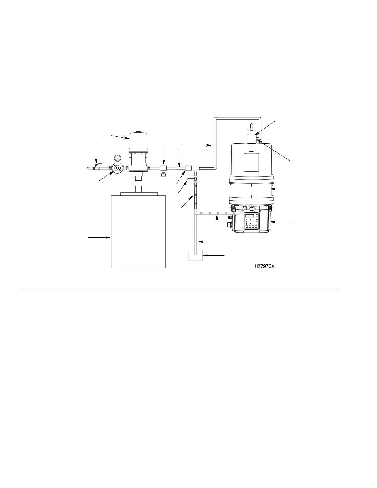
Optional Installation - Without Remote Fill Manifold
The installation shown is only a guide for selecting and installing system components. Contact your Graco distributor
for assistance in planning a system to suit your needs.
NOTE: The remote filling station pump stalls (dead-heads) when the reservoir is full. If the pump does not stall
(dead-head) there is a leak in the system.
FIG. 5
Key:
AG3 Pump
B Auto-Fill Shut Off Valve
C Auto-Fill Inlet
D G3 Reservoir
E Remote Fill Reservoir
F Remote Fill Pump
HRelief Valve
J Supply Hose (user supplied)
LDrain Tube
L1 Option - To reservoir
L2 Option - To overflow container
S Pressure Regulator and Gauge
U Pressure Relief Valve
V Quick Disconnect
W Overflow Container
Y Supply Hose Pressure Relief Valve
To relieve the stall pressure in the fill line a ball valve
(Y) must be installed in the system.
10 332298E
Page 11
Choosing an Installation Location
AUTOMATIC SYSTEM ACTIVATION HAZARD
If the system is equipped with has an auto matic timer
(user supplied) that activates the pump lubrication
system when power is connected or when exiting the
programming function, unexpected activation of the
system could result in serious injury, including skin
injection and amputation.
Before you install or remove the lubrication pu mp
from the system, disconnect and isolate all power
supplies and relieve all pressure.
• Select a location that will adequately support
the weight of the G3 Pump and lubricant, as
well as all plumbing and electrical connections.
• Refer to the mounting hole layouts provided in
the Mounting Pattern section of this manual,
page 42. No other installation configuration
should be used.
Installation
• Use designated mounting holes and pr ovided
configurations only.
• Always mount the G3 oil models upright.
• If the G3 grease model is going to be operated
in a tilted or inverted position for any period of
time, you must use a model that includes a follower plate, otherwise the G3 must be mounted
upright. Refer to your model number to confirm
if a follower plate was installed on your pump.
See page 4, Understanding the Model Number
to identify this character in your model number.
• Use the three faste ners (included) to secure t he
G3 to the mounting surface.
• Some installations may require an additional
reservoir support bracket. See Table below for
bracket information
Part No Description
571159 Reservoir bracket and strap
125910 L-Bracket for pump
127665 USP to G-Series mounting bracket
332298E 11
Page 12

Installation
System Configuration and Wiring
Grounding
The equipment must be grounded to reduce the risk
of static sparking and electric shock. Electric or static
sparking can cause fumes to ignite or explode.
Improper grounding can cause electric shock.
Grounding provides an escape wire for the electric
current.
Improper installation of the groundin g conductor may
result in a risk of electric shock. This product must be
installed by a qualified electrician in compliance with
all state and local codes and regulations.
If the product is permanently connected:
• It must be installed by a qualif ied electrician or serviceman.
• It must be connected to a grounded, permanent wiring system.
If an attachment plug is required in the end use
application:
• It must be rated for the product electrical specifications.
• It must be an approved, 3-wire grounding type
attachment plug.
Fuses
NOTICE
Fuses (user supplied) are required on all DC models. To avoid equipment damage:
• Never operate G3 Pump DC models without a
fuse installed.
• A fuse of the correct v oltage must be in stalled in
line with the power entry to the system.
Fuse Kits are available from Graco. The following Table
identifies the correct fuse to use for your input voltag e
and the corresponding Graco Kit number.
Input Voltage
12 VDC
24 VDC
Fuse Value
7.5 A
4 A
Graco Kit No.
571039
571040
Recommendations for Using Pump in
Harsh Environments
• Use pump with CPC style power cable.
• If using a DIN style power or alarm harness with a
right angle mating connector, make sure the connector does not exit the unit in the UP direction.
• Use a corrosion prev entat iv e electrical grease on all
contacts.
• It must be plugged into an outlet that is properly
installed and grounded in accordance with all local
codes and ordinances.
• When repair or replacement of the power cord or
plug is required, do not connect the grounding wire
to either flat blade terminal.
12 332298E
Page 13
Installation
Remote Illumination Response
The following tab les include g raphica l representations of the connector as it appear s on the unit, a pin-out a ssociated
with the connector and a typical installation wiring diagram. An internal representative wiring diagram is included
where it is deemed useful.
Wire colors provided on these pages only refer to the power cable provided by Graco with this product.
Standard Remote Illumination
(via 5 wire CPC power cable)
Unit in OFF Mode Off Off
Unit in ON Mode On Green
Warning Condition Toggles On and Off once per second Yellow
Fault Condition Toggles On and Off once per second Red
Tri-Color Remote Illumination
Wiring and Installation Diagrams
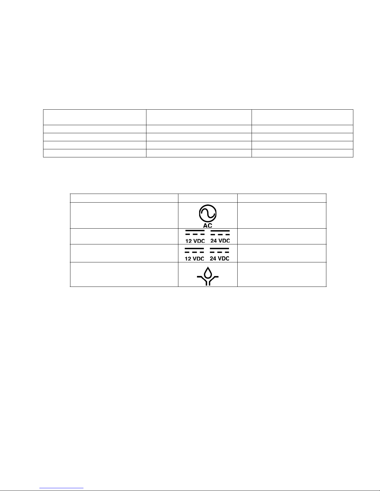
The following Table identifies the wiring and installation diagrams provided in this manual.
Diagram Symbol Page #
Power DIN AC 14
Power DIN DC 14
Power CPC DC 15
Illuminated Manual Run Input
Kits: 571030, 571031,
571032, 571033
(M12 Connector)
332298E 13
Page 14
Installation
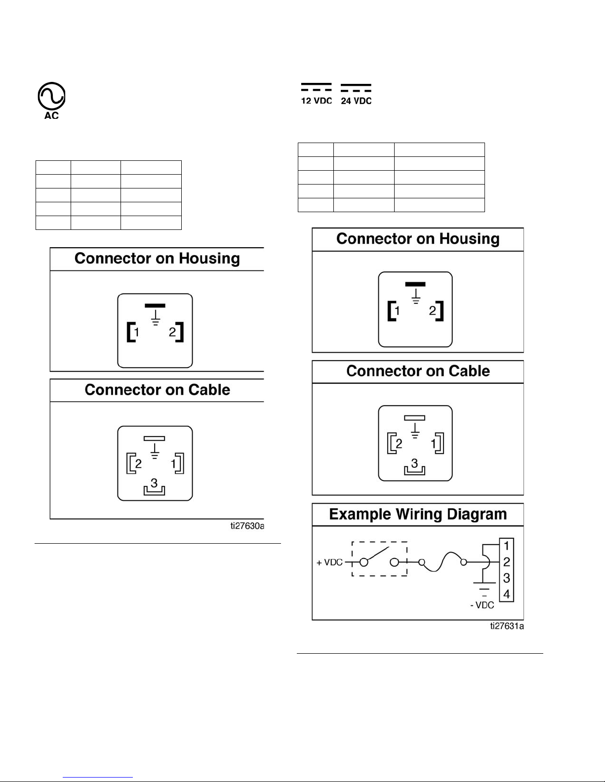
Power DIN AC - 15 foot
Pin and Related Wire Color (FIG. 6)
Pin Pin Name Color
1 Line Black
2Neutral White
3 Not Used Not Used
4
Ground Green
Power DIN DC - 15 Foot
Pin and Related Wire Color (FIG. 7)
Pin Pin Name Color
1-VDC Black
2+VDC White
3 Not Used Not Used
4
Not Used Green
FIG. 6
14 332298E
FIG. 7
Page 15

Installation
Power CPC DC -15 foot
Pin and Related Wire Color (FIG. 8)
Pin Pin Name Color
1 Not Used Not Used
2-VDC Black
3+VDC White
4 Not Used Not Used
5 Not Used Not Used
6 Not Used Not Used
7 Not Used Green
Power CPC DC - 5 Wire
Part No.: 127780: 15 ft (4.5 m)
Part No.: 127781: 20 ft (6.1 m)
Part No.: 127782: 30 ft (9.1 m)
An Illuminated Remote Run Button Kit: 571030, 57 1031
for starting a manual run cycle if used in conjunction
with a 5-wire CPC cable, is available from Graco. Contact your local Graco distributor or Graco Customer Service for additional information about these kits.
Pin and Related Wire Color (F
Pin Pin Name Color
1 Not Used Not Used
2-VDC Black
3+VDC Red
4LIGHT White
Manual Run
5
Switch
6 Not Used Not Used
7 Not Used Green
IG. 9)
Orange
FIG. 8
332298E 15
FIG. 9
Page 16

Installation
Part No. 124333: Cable Pin Out (M12)
Wire Colors (FIG. 10)
Item No. Color
1Brown
2White
3Blue
4Black
Part No. 124300: Field Wireable Pin Out
(M12)
Wire Colors (FIG. 12)
Item No. Color
1Brown
2White
3Blue
4Black
FIG. 10
Part No. 124595: 5 Pin Eurofast Field
Wireable Connector
FIG. 11
FIG. 12
Part No. 124594: 4 Pin Eurofast Field
Wireable Connector
FIG. 13
16 332298E
Page 17

Setup
Setup
Pressure Relief
Follow the Pressure Relief Procedure whenever
you see this symbol.
This equipment stays pressurized until pressure is
manually reliev ed. To help prevent serious injury from
pressurized fluid, such as skin injection, splashing
fluid and moving parts, follow the Pressure Relief
Procedure when you stop dispensing and before
cleaning, checking, or servicing the equipment.
Relieve pressure in system using two wrenches
working in opposite directions on pump element and
pump element fitting to slowly loosen fitting only until
fitting is loose and no more lubricant or air is leaking
from fitting.
NOTE: When loosening pump elem ent fitting, do NOT
loosen pump element. Loosening pump element will
change the output volume.
Connecting to Auxiliary Fittings
NOTICE
Do not attach unsupported equipment to auxiliary fittings such as fill ports and pump element. Attaching
unsupported equipment to these fitting can result in
irreparable housing damage.
• Always use two wrenches w orking in opposite
directions when connecting anything to pump element or auxiliary fittings. See F
ple.
• Torque pump element fittings to 50 in. lbs (5.6
N•m).
• When connecting pump element into housing
torque to 50 in. lbs (5.6 N•m).
Pressure Relief Valves
To prevent over-pressurization, which can result in
equipment rupture and serious injury, a pressure
relief valve appropriate for the lubrication system
must be installed close to every pump outlet to alleviate unintended pressure rises in the system and protect the G3 pump from damage.
IG. 14 for an exam-
IG. 14
F
332298E 17
• Only use a pressure relief valve that is rated for
no more than the working pressure of any component installed in the system. See Technical
Data, page 37.
• Install a pressure relief valv e close to ev ery pump
outlet; before any auxiliary fitting.
NOTE: A pressure relief valve can be purchased from
Graco. See Parts, page 40.
Page 18

Setup
D
Setting Pump Outlet Volume
NOTE:
• Before making an y adjustments to pump volume,
Relieve Pressure following procedure on page 17.
• Only use Graco supplied spacers to control output
volume.
1. Use a wrench to turn pump element counter-clockwise to loosen. Do not remov e entire pump element.
Only back pump element out enough to allow
spacer to be slid on or off.
If needed, remov e or insert spacers to achieve required
pump output volume. A tool may be needed to facilitate
removal.
Pump volume control is set using eithe r no (0) spacers,
1 or 2 spacers (F
Do not use more than 2 spacers to adjust output volume.
IG. 15).
FIG. 15
Loading Grease
To ensure optimal performance from the G3:
• Only use NLGI #000 - #2 greases appropriate for
your application, automatic dispensing, and the
equipment’s operating temperature. Consult with
machine and lube manufacturer for details.
• The reservoir can be filled using a hand operated
pump, pneumatic pump or electric transfer pump.
• Do not overfill (F
IG. 18).
Output Volume / Minute
No. Spacers
20.122
10.183
00.254
• The amount of dispensed volume can vary depending on external conditions such as lubricant temperature and back pressure from downstream
connections.
• Use of these volume adjustment in conjunction with
setting the ON time of the pump will allow for control
of the output volume.
• Use these volume adjustments as a starting point
and adjust as necessary to ensure desired lubrication dispense.
2. Tighten pump element fitting. Torque fitting to 50 in.
lbs (5.6 N•m).
cubic inches cubic cm
• Do not operate G3 without reservoir attached.
NOTICE
• Always clean inlet fitting (D) (FIG. 16) with a
clean dry cloth prior to filling reservoir. Dirt
and/or debris can damage pum p an d/ or lubrication system.
• Care must be used when filling the reservoir
using a pneumatic or electric transfer pump to
not pressurize and break the reservoir.
IG. 16
F
18 332298E
Page 19

Setup
D
E
max fill line
vent hole
Models without a follower plate:
1. Connect fill hose to inlet fitting (D) (FIG. 17).
FIG. 17
2. For higher viscosity fluids, start pump to rotate stirring paddle during fill to prevent air pockets from
forming in grease.
Start pump by pressing the manual run
button.
3. Fill reservoir with NLGI grease to max
fill line.
Models with a follower plate:
1. Connect fill hose to inlet fitting (D) (FIG. 17).
2. For higher viscosity fluids, start pump to rotate stirring paddle during fill to prevent air pockets from
forming in grease.
Start pump by pressing the manual run
button.
3. Fill reservoir with grease until seal of
follower plate breaches the vent hole (F
the majority of air is expelled from the reservoir.
IG. 19) and
NOTE: Vent port, located in rear of reservoir, should not
be used as an overfill port/indicator.
FIG. 18
4. Remove fill hose.
FIG. 19
NOTE: Vent port, located in rear of reservoir, should not
be used as an overfill port/indicator.
4. Remove fill hose.
Changing Greases
When changing greases, always use compatible fluids
or greases.
332298E 19
Page 20

Setup
pin
down
Auto-Fill Shut Off
Loading Grease
To ensure optimal performance from the G3:
• Only use NLGI #000 - #2 greases appropriate for
your application, automatic dispensing, and the tem perature. Consult with machine and lub e manufacturer for details.
• Do not overfill.
• Do not operate G3 without reservoir attached.
NOTICE
Care must be used when filling the reservoir using a
pneumatic or electric transfer pump t o not pressurize and break the reservoir.
Changing Greases
When changing greases, always use compatible fluids
or greases.
The Auto-Fill Shut Off is used for refilling the G3 reservoir in an automatic lubrication system. As fluid is added
to the reservoir , it pushes the plat e v alv e up to the t op of
the reservoir. The plate valve then pushes the valve pin
and closes the inlet fluid path.
COMPONENT RUPTURE HAZARD
The maximum working pressure of each component
in the system may not be the same. To reduce the
risk of over-pressurizing any component in the system, be sure you know the maximum working pressure of each component. Never exceed the
maximum working pressure of the lowest rated component in the system. Over-pressurizing any component can result in rupture, fire, explosion, property
damage and serious injury.
Regulate input pressure to the remote fill pump so
that no fluid line, component or accessory is over
pressurized.
Remote Fill with Remote Fill Manifold
The reference letters used in the following instructions
refer to the Typical Installation diagram, page 9.
The fill valve is used to relieve pressure in the refill line
and to reset the Auto Fill Shut Off . See Fill Valve instruction manual 333393. Graco fill valve, part no. 77X542 is
available. Contact your local Graco distributor.
When the fluid refilling path closes, the refilling line pressurizes and brings the refilling pump to a pressurized
stall condition.
NOTE: The operator must monitor system while filling
the reservoir to prevent overfilling.
The remote filling station pump stalls (dead-heads)
when the reservoir is full, causing the supply system
pressure to rise to the maximum output pressure
of the filling station pump. To help prevent equipment
damage or serious injury caused by pressurized fluid,
such as skin injection or injury from splashing fluid,
always use a remote filling station pump with a maximum output pressure of 5100 psi (35.1 MPa,
351.6 bar) and use supply hoses with a minimum
pressure rating of 5100 psi (35.1 MPa, 351.6 bar).
1. Pull out and hold the Pressure Relief Knob (T) long
enough to relieve line pressure between Fill Manifold (N) and Auto-Fill Shut Off Valve (B).
2. Verify the Auto-Fill Shut Off (B) pin is down, indicating it is reset (F
FIG. 20
3. Remove yellow Dust Cover from Fill Coupler (M).
IG. 20).
20 332298E
Page 21

Setup
pin
up
pin
up
4. Connect Supply Hose (J) between the Remote Filling Station Pump (F) and Fill Coupler port marked
with an “I”.
5. Start Remote Filling Station Pump (F).
6. When the G3 Reservoir (D) is filled:
• the Remote Filling Station Pump (F) stalls
(dead-heads),
• the Auto-Fill Shut Off (B) pin pops up as shown
IG. 21,
in F
• the Pressure Gauge (R) rises to the fill pump’s
set pressure.
NOTE: If the pump does not stall (d ead-hea d) th ere is a
leak in the system.
Remote Fill without Remote Fill Manifold
The reference letters used in the following instructions
refer to the Typical Installation diagram, page 10.
1. A supply hose pressure relief valve (Y) and o v erflow
container (W) (for collecting excess fluid that drains
during pressure relief) must be installed in an easily
accessible location between the remote filling station pump (F) and the Auto-Fill Shut Off (B). This
pressure relief valve is used to relieve pressure in
the refill line and to reset the Auto-Fill Shut Off. See
Typical Installation, starting on page 8.
A Pressure Relief Kit: 247902 is available from
Graco. Contact your distributor or Graco Customer
Service for additional information about this kit.
2. Connect Supply Hose (J) at Quick Connect (V).
3. Turn on remote filling station pump (F) and fill the
G3 reservoir (D) until the indicator pin on the
Auto-Fill Valve pushes up as shown in F
pressure in the refill pump (F) builds and the pump
stalls.
IG. 22. The
FIG. 21
NO
7. Turn off the Remote Filling Station Pump (F).
8. Pull out and hold the Pressure Relief Knob (T) long
enough to relieve line pressure between Fill Manifold (N) and Auto-Fill Shut Off Valve (B) and
between Remote Filling Station Pump (F) and Fill
Manifold (N).
NOTE: The length of time it takes to vent v aries depend ing on the system design and installation. In some
installations it may be necessary to repeat Step 8 to
ensure pressure is relieved.
9. Disconnect Supply Hose (J) at Fill Coupler (M).
10. Replace yellow Dust Cover over Fill Coupler (M).
332298E 21
FIG. 22
4. Turn off the air supply (H) to pump (F).
5. Relieve remote filling station pump pressure using
the following Remote Filling Station Pressure Relief
procedure:
Page 22

Setup
Y
L
W
a
b
Remote Filling Station Pressure Relief
The reference letters used in the following instructions
refer to the Typical Installation diagrams starting on
page 8.
The following Pressure Relief Procedure is only
used with the Auto-Fill Shut Off Valve to relieve
remote filling station and lubricant supply line
pressure.
This equipment stays pressuriz ed until pressure is
manually relieved. To help prevent serious injury from
pressurized fluid, such as skin injection, splashing
fluid and moving parts, follow the Pressure Relief
Procedure when you stop dispensing and before
cleaning, checking, or servicing the equipment.
a. To relieve pressure between the Refill Pump (F)
and Auto-Fill Shut Off (B), open ball valve (bv)
IG. 23). Pressure will be released and excess
(F
fluid will drain out of the drain tube (L) and into
the lubrication overflow container (W).
Filling Oil Unit
• Only use oil appropriate for your application, automatic dispensing, and the equipment’s operating
temperature. Consult with machine and lube manufacturer for details.
• Do not overfill (F
• Do not operate G3 without reservoir attached.
• Only use oils with viscosity at least 40 cSt.
FIG. 24
1. Remove fill cap (a).
2. Pour oil into reservoir to max fill line (b).
3. Replace fill cap. Hand tighten cap, securely.
IG. 24).
FIG. 23:
b. Close supply hose pressure relief valve (Y)
when all pressure has been relieved.
6. Disconnect the supply hose (J) from Quick Connect
(V).
22 332298E
Page 23

Setup
Priming
NOTE: It is not necessary to prime pump every time
pump is filled with lubricant.
Pump only requires priming the first time it is used or if it
is allowed to run dry.
1. Loosen pump element fitting (F
NOTE: When loosening pump elem ent fitting, do NOT
loosen pump element. Loosening pump element will
change the output volume
IG. 25).
2. Only run pump until air is no longer dispensed with
the lubricant coming out of element fitting (F
IG. 26).
FIG. 26
3. Tighten pump element fitting using two wrenches
working in opposite directions (F
IG. 25).
FIG. 25
332298E 23
Page 24

Quick Setup Guide
Quick Setup Guide
24 332298E
Page 25

Pro Model Setup
ON
OFF
!
HH MM
SS ##
MM : SS HH : MM
DISPLAY
• A blinking LED under HH, MM, SS or ##
indicates type of measurement unit you
are setting; i.e., HH is hours.
• A blinking number on the display indi-
cates the G3 is in SETUP MODE.
• In RUN MODE display ed n umbers count
up or down. See Time ON and Time
OFF.
ON TIME
• LED lights when ON Time
sequence is running.
• Display shows time as MM:SS
(minutes and seconds).
i.e., 08:30 is 8 minutes: 30 seconds.
• Times lubrication cycle.
OFF TIME
• LED lights when OFF Time sequence is
running.
• Value is entered in HH:MM.
• Displays in HH:MM (hours and minutes)
when > 1 hour.
• Displays in MM:SS (minutes and second)
ALARM ICONS
LED next to icon lights when a
fault / warning event occurs
during a run cycle. See page 33
for a complete description of
these alarm scenarios.
LOCK ICON
• LED next to icon lights indi-
cating PIN is required to
enter setup.
• In SETUP MODE LED
lights when setting up the
PRELUBE
LED next to icon lights indicating Prelube function is enabled.
LEFT DIRECTION ARROW /
RESET
• In SETUP MODE: moves cur-
sor in display one field to the
left.
• In RUN MODE: single press
clears warning.
• In RUN MODE: pressing for
one second ends run cycle if
there are no warnings.
• In ALARM MODE: pressing and
holding for 3 seconds clears
fault / warning and switches
cycle to OFF MODE.
RIGHT DIRECTION ARROW /
MANUAL RUN / ENTER:
• In SETUP MODE: saves
entry, moves cursor in display
one field to the right or to the
next setup step.
• In RUN MODE: starts a man-
ual run cycle.
UP and DOWN ARROW
• Hold both the UP and DOWN ARROW but-
tons down together for 3 seconds to enter
SETUP MODE.
• In SETUP MODE, increases or decreases
number values shown in display.
Control Panel Overview (FIG. 27)
NOTE: Programming instructions begin on page 26.
Pro Model Setup
FIG. 27
332298E 25
Page 26

Pro Model Setup
Instructions
Powering Units With Controllers
By default, units with controllers are set to
operate in a timed mode with 1 minute of
ON time and 8 hours of OFF time. The unit
should be powered up in OFF mode,
counting down from the 8 hours. If the unit power s u p in
ON mode and has not been primed, hold the reset button located on the control panel (example shown on the
right) for 1 second to move to the OFF mode.
The Pro Model uses a timer to regulate how long a
pump cycle runs and the length of time the pump rests
between cycles.
NOTE:
• A blinking number on the display indicates the G3 is
in SETUP MODE.
• In RUN MODE numbers on the display do not blink.
• After 60 seconds of no activity , the de vice returns to
RUN MODE in the OFF Time cycle and the OFF
Time restarts co un tin g down the tot al pr ogrammed
amount of time. It does not resume the countdown
from the point where the cycle was interrupted when
you entered SETUP MODE.
Entering Setup Mode
Press both the UP and DOWN
ARROW buttons together for 3
seconds to enter the SETUP
MODE.
NOTE: If the loc k LED is
lit after entering Setup
Mode and four 0000’s
are displayed, the unit
has a PIN Code lock out
enabled. See Entering a
PIN Code to Access
Setup Mode for instructions on entering a value.
Entering a PIN Code to Access Setup Mode
The G3 controller does not require a user to provide a
PIN code to access the programming features of the
unit. However, Gr aco u nderst ands t hat som e users m ay
want to protect the program settings and therefore, an
option for adding PIN Code authorization is available.
The instructions for setting a PIN Code are provided in
the Advanced Program ming section of this man ual. See
page 29.
To enter the PIN Cod e :
1. Press both the UP and
DOWN ARRO W b uttons for 3
seconds.
2. The LED next to the LOCK ICON on
the display lights and the 4 zeros
appear on the display indicating the
system requires a PIN Code entry to access the G3
in SETUP MODE.
3. The cursor is automatically
positioned to enter the first
character of the PIN Code.
Use the UP and DOWN
ARROW buttons to move up
and down through the numbers 0-9 until the first
number in the PIN code is displayed in the field.
4. Press the ENTER button to set the number. The cursor automatically moves to
the next number fie ld.
5. Repeat steps 3 and 4 for each PIN Code prompt
field.
If the PIN Code you entered is correct, the first editable
character on the display will flash.
NOTE: A blinking fie ld on the di spla y indica tes the G3 is
in SETUP MODE. In RUN MODE numbers on the display will not blink.
ON Time
26 332298E
• The LED next to the clock in the ON
field lights, indicating you are setting
the ON Time parameters.
• ON Time is set in Minutes and Seconds (MM: SS).
Page 27

Pro Model Setup
OR
OR
• An LED flashes under
either MM when programming minutes
OR SS when programming seconds.
• In SETUP MODE, the
number displayed in
the first field, on the
left side of display
blinks, indicating the
device is ready to program the ON Time minutes.
• The total amount of ON Time cannot
exceed 30 minutes. If a value greater
than 30 minutes is entered, the RED
alarm LED lights and the value must
be updated.
If this time does not meet the application needs,
contact Graco Customer Support.
Programming ON Time
NOTE: When programming a time of less than 10 min-
utes you must program a leading zero in the first number field and press the ENTER button to save the zero
selection.
1. To set the ON Time use the
UP or DOWN AR RO W bu tton
to scroll through numerals 0
to 5 until the desired number
appears in the first MM (minutes) field.
2. Press the ENTER button to lock in the
selection. The next MM number field to
the right flashes indicating it is ready for
programming.
5. Repeat steps 1 - 4 to set the SS (seconds) fields.
6. After pressing the ENTER button to set
the last SS field, all the programm ed ON
Time information is saved.
The G3 automatically switches to the OFF Time
SETUP MODE.
OFF Time
• The LED next to the clock in the OFF
field lights, indicating you are setting
the OFF Time parameters.
• OFF Time is set in Hours and Minutes
(HH: MM).
• An LED flashes under
either HH when programming hours OR
MM when programming minutes.
• In SETUP MODE the
number displayed in
the first field, on the
left side of display
blinks, indicating the
device is ready to program the OFF Time hours.
• The total amount of OFF Time m ust be
at least twice as long as the programmed ON Time. If a value less than
twice the ON Time is entered, the RED
alarm LED lights and the value must be updated.
If this time does not meet the application needs,
contact Graco Customer Support.
3. Use the UP or DOWN
ARROW button to scroll
through numerals 0 to 9 until
the desired number appears
in the second MM number
field.
4. Press the ENTER button to lock in the
selection.
The next number field to the right
flashes and the LED lights under SS; indicating it is
ready to program the seconds fields.
332298E 27
Programming OFF Time
NOTE: When programming a time of less than 10
hours you must program a leading zero in the first num-
ber field and press the ENTER button to save the zero
selection.
1. To set the OFF Time use the
UP or DOWN ARRO W button
to scroll through numerals 0
to 9 until the desired number
appears in the first HH (hour)
field.
Page 28

Pro Model Setup
2. Press the ENTER button to lock in the
selection. The next HH number field to
the right flashes indicating it is ready for
programming.
3. Use the UP or DOWN
ARROW button to scroll
through numerals 0 to 9 until
the desired number appears
in the second HH number
field.
4. Press the ENTER button to lock in the
selection.
The next number field to the right
flashes and the LED lights under MM; indicatin g it is
ready to program the minutes fields.
5. Repeat steps 1 - 4 to set the next MM (minutes)
fields.
6. After pressing the ENTER button to set
the last MM field, the OFF Time information is saved.
Prelube
The Prelube function determines operation of the pump
when power is applied. It can be set to OFF or ON.
4. If you want to set a
prelube delay time,
press the DOWN
ARROW button to
change OFF to ON
on the display.
Prelube Delay
Prelube Delay can be entered t o delay the start of the
pump’s cycle on p ower up. If pr elu be is set to ON, a prelube delay time in MM:SS must be entered. By default,
the delay is set to 0 (begin an ON cycle immediately).
Delaying the prelube function may be desired if other
critical functions or systems of your machine or vehicle
are also coming on line during power up.
1. Prelube Delay is set in
MM:SS (minutes and seconds). To set the time use the
UP or DOWN ARRO W button
to scroll through numerals 0
to 5 until the desired number
appears in the first MM (minutes) field.
The maximum length of time Prelube Delay can be
set to is 59:59 (59 minutes:59 seconds).
OFF (default) - The unit resumes its lubrication cycle at
the point it was at when power was removed.
ON - The unit begins a pump cycle.
Setting Prelube
1. After you set the OFF Time information and press
the ENTER button, the G3 automatically switches to
the Prelube setup.
Notice the LED next to the prelube
icon on the G3 display lights indicating you are now in the Prelub e setup
mode.
2. OFF displays. If you
want the prelube
cycle to begin immediately, leave this set
to OFF.
3. Press the ENTER button to set the
selection.
2. Press the ENTER button to lock in the
selection. The next MM number field to
the right flashes indicating it is ready f or
programming.
3. Use the UP or DOWN
ARROW button to scroll
through numerals 0 to 9 until
the desired number appears
in the second MM number
field.
4. Press the ENTER button to lock in the
selection.
The next number field to the right
flashes and the LED lights under SS; indicating it is
ready to program the seconds fields.
5. Repeat steps 1 - 4 to set the SS (seconds) fields.
6. After pressing the ENTER button to set
the last SS field the G3 automatically
switches to the RUN MODE.
28 332298E
Page 29

Advanced Programming
Advanced Programming
There are 2 Advanced Programming options. The following Table identifies each option and when it is used.
Advanced
Option
A1 Lockout
A2 Low Level
Setting Format/ Description Why Use This?
Secures setup modes with PIN Prevents unauthorized users to adjusting settings.
Code
(Optional)
MM:SS (minutes:seconds) sets
Alarm Time
amount of time between Low Le v el
Warning to Low Level Fault.
Default = 3 minutes
Entering a PIN Code for the First Time
A1-Setting Up PIN Code
A PIN Code can be programmed into the G3 to protect
the settings from inadvertently being changed by unauthorized users.
1. Press the UP ARROW button for 10
seconds.
The LED next to the LOCK ICON on the display lights, indicating you have entered the
PIN Mode.
2. The word OFF appears in the
display. Press the UP or
DOWN ARROW button to
change this to ON.
3. Press the ENTER button to enter the
PIN Code.
4. The cursor automatically is
positioned to entered the first
character of the PIN Code.
Use the UP and DOWN
ARROW buttons to move up
and down through the numbers 0-9 until the first
number in the PIN code is displayed in the field.
To accommodate most lubrication situations, a conservative amount of time is programmed between
the low level warning and fault to help protect unit
from running dry . If necessary the amount of time the
unit runs before stopping due to a low level fault can
be adjusted.
6. Repeat steps 4 and 5 for each PIN Code prompt
field.
7. Press the ENTER button to save the
PIN Code and exit Advanced Setup.
Entering Advanced Setup
Press the UP ARROW button for 10 seconds.
If the G3 was previously set up to require a
PIN Code, the LED next to the LOCK ICON lights, indicating a PIN Code is required.
1. The cursor is automatically
positioned to enter the first
character of the PIN Code.
Use the UP and DOWN
ARROW buttons to move up
and down through the numbers 0-9 until the first
number in the PIN code is displayed in the field.
2. Press the ENTER button to set the number. The cursor automatically moves to
the next number fie ld.
3. Repeat steps 1 and 2 for each PIN Code prompt
field.
If the PIN Code you entered is correct, the first editable
character on the display will flash.
5. Press the ENTER button to set the number. The cursor automatically moves to
the next number field.
332298E 29
Page 30

Advanced Programming
ON
OFF
!
HH MM
SS ##
MM : SS HH : MM
Selecting Advanced Setup Options
1. Press the UP or DOWN
ARROW button to mov e up or
down through Advanced
Options A1 and A2.
2. Press the ENTER button to set the
selection.
A2 - Low Level Alarm Time
Pump ON mode only.
Programs the amount of time in MM: SS (minutes and
seconds) the pump can run between a Low Level Warning and a Low Level Fault to help protect unit from running dry.
The maximum recommended length of time is 3:00 minutes.
Fault, and Low Level LED illuminate.
1. To set t he ti me use the UP or
DOWN ARROW button to
scroll through numerals 0 to 9
until the desired number
appears in the first MM (minutes) field.
2. Press the ENTER button to lock in the
selection. The next MM number field to
the right flashes indicating it is ready f or
programming.
3. Use the UP or DOWN
ARROW button to scroll
through numerals 0 to 9 until
the desired number appears
in the second MM number
field.
4. Press the ENTER button to lock in the
selection.
The next number field to the right
flashes and the LED lights under SS; indicating it is
ready to program the seconds fields.
FIG. 28
NOTE: When programming a time of less than 10 min-
utes you must program a leading zero in the first number field and press the ENTER button to save the zero
selection.
5. Repeat steps 1 - 4 to set the SS (seconds) fields.
6. After pressing the ENTER button to set
the last SS field, all the programmed O N
Time information is saved.
Unit exits Advanced Programming.
30 332298E
Page 31

Run Mode
ON
OFF
!
HH MM
SS ##
MM : SS HH : MM
ON
OFF
!
HH MM
SS ##
MM : SS HH : MM
Run Mode
Time Control
After setup is complete, the G3 automatically begins to
run the OFF Time sequence (F
• The G3 runs the programmed OFF sequence.
(Notice the OFF Time LED on the displa y light s and
the OFF Time counts down on the display.)
• The example shown in F
of 1 hour and 32 minutes before the lubrication cycle
begins.
IG. 29).
IG. 29 shows an OFF Time
• When the OFF Time count reaches zero, the G3
Automatic Lubrication Pump turns the pump on and
it runs for the programmed ON Time cycle (F
(Notice the ON Time LED is now illuminated on the
display.)
• The example shown in F
8 minutes and 42 seconds before the lubrication
cycle ends.
IG. 30 shows an ON Time of
IG. 30).
FIG. 30
• When the ON Time count reaches zero, the pump
shuts off again and the system again runs OFF
Time cycle and the OFF Time LED is now again illu-
IG. 29).
FIG. 29
minated (F
This sequence repeats itself until the device is
reprogrammed or an alarm occurs.
Manual Run Cycle
To run an extra (non-programmed) lubrica-
332298E 31
tion cycle, push the Manual Start button.
Page 32

Run Mode
ON
OFF
!
HH MM
SS ##
MM : SS HH : MM
Additional Controls
Prelube / Prelube Delay
In all models a power OFF/ON cycle can be controlled
with the Prelube and Prelube Dela y functions.
Prelube
The Prelube function has been selected. Prelube delay
is set to 00:00:
• Power to the unit cycles OFF then ON.
• Unit immediately begins a lubrication cycle.
• Pro Model - display shows ON Time (See Time
Control, page 31).
Prelube Delay
The Prelube function has been selected. Prelube delay
is set to something other than 00:00:
• Power to the unit cycles OFF then ON.
• Unit immediately begins the Prelube Delay
count down until the lubrication cycle begins.
• The LED next to the clock in the OFF field is illuminated (F
• The Prelube LED lights (F
IG. 31).
IG. 31).
• The display shows time remaining until lubrication cycle begins. The ex ample shown in F
shows 8 minutes and 14 seconds left until a
lubrication cycle begins.
IG. 31
IG. 31
F
Manual Run Cycle
To run an extra (non-programmed) lubrication cycle, push the Manual Start button.
NOTE: Manual Run option is not available while unit is
in Vent Mode.
32 332298E
Page 33

Alarms
Alarms
Any time a Fault / Warning occurs, a combination of LED’s will illuminate to notify you there is a problem and help
identify the kind of Fault / Warning has occurred.
• Faults and Warnings will not automatically clear.
• To clear an fault, press and hold the RESET button on the display button pad for 3 seconds.
• To clear a warning press and immediately release the RESET button.
Fault / Warning Scenarios
The following pages describe the most likely fault / warnings you could receive.
Alarm Type What it Looks Like What it Indicates Solution
Low Level
Warning
HH MM
ON
MM : SS HH : MM
SS ##
OFF
!
Level of lubricant in
reservoir is low and additional lubricant needs to be
added.
Unit continues to operate
as normal for a limited
Add lubricant to reservoir.
After lubricant
is added,
press the
RESET but-
ton to clear the warning.
period of time until a low
level alarm is triggered.
Low Level
Fault
HH MM
ON
MM : SS HH : MM
SS ##
OFF
!
Level of lubricant in
reservoir is low and additional lubricant needs to be
added.
Unit stops pumping and
displays amount of accumulated time since the
Add lubricant to reservoir.
After lubri-
cant is
added press
and hold the
RESET button to clear
fault.
alarm was triggered.
If repriming pump is
required, the low level
alarm time should be
decreased. See A-2:
Advanced Programming,
Low Level Alarm Time
page 30.
332298E 33
Page 34

Troubleshooting
Troubleshooting
Problem Cause Solution
Unit does not power on
Unit does not power on (DC models
only)
Unit does not power on (AC models
only)
Can’t set desired ON/OFF times
Unit is not operating based on the time
that was programmed
Lubricant leaks past seal located on
the bottom of the reservoir
Unit not pumping during ON cycle, but
controller lights and functions
Follower plate is not going down
Pump takes several minutes before it
begins pumping at the highest pump
volume setting (no stroke adjust spacers installed)
Dim display, unit is not operating
Incorrect/loose wiring Refer to Installation instructions, page
7.
Tripped external fuse due to internal
component failure
Tripped external fuse due to pumping
non-cold weather lubricant in cold
weather -13°F (-25°C)
Tripped internal power supply fuse due
to power supply failure
Maximum duty cycle is 33% (2 minutes
OFF for each minute ON)
Time entered was misinterpreted as
MM:SS instead of HH:MM (or visa
versa)
Reservoir retaining tabs are cracked or
broken
Reservoir is being pressurized during
filling
Failed motor Replace unit.
Air is trapped in the reservoir between
the follower plate and lubricant
Pumping non-cold weather lubricant in
cold weather -13°F (-25°C)
Tripped internal, resettable fuse due to
internal component failure or sensor
short circuit condition
Contact Graco Customer Service.
Replace lubricant with pumpable lubri-
cant, rated for environmental conditions
and application.
Replace fuse.
Contact Graco Customer Service.
Adhere to allowable duty cycle. Contact
Graco Customer Support if other duty
cycles are required for application.
Verify the unit was programmed as
intended, referencing programming
instructions. Note the dot designation
for hours, minutes, seconds on the top
row of the display.
Replace reservoir.
Ensure vent hole is not plugged.
If problem persists, contact Graco Cus-
tomer Service or your local Graco distributor for assistance.
Add grease following Loading Grease
instructions, page 18. Ensure air is
purged.
Add 1 stroke adjust spacer and adjust
lube cycle time to accommodate the
difference in pump volume per stroke.
Verify sensor and manual run inputs
have not created a short circuit condition. Cycle power.
34 332298E
Page 35

Maintenance
Maintenance
Frequency Component Required Maintenance
Daily and at refill Zerk Fittings Keep all fittings clean using a clean
dry cloth. Dirt and/or debris can damage pump and/or lubrication system.
Daily G3 Pump Unit and Reservoir Keep pump unit and reservoir clean
using a clean dry cloth.
Daily Display Keep display clean using a clean dry
cloth.
Monthly External Wiring Harness Verify ex ternal harnesses are secure.
332298E 35
Page 36

Parts - 2 Liter Models
35
16
15
27
1
45
60
23
57
40a
44
14
1
42
13
18
17
34
36
33
37
41
21
30
15
4
3
31
Follower Plate Models
43
Torque to 4 in. lbs (0.45 N.m)
1
Torque to 30 in. lbs (3.4 N.m)
2
Torque to 50 in. lbs (5.6 N.m)
3
2
3
40b
3
Low Level Grease Models
Low Level Oil Models Only
66
67
12
Parts - 2 Liter Models
36 332298E
Page 37

Parts - 4 Liter and Larger Models
40a
44
35
14
1
41
13
18
17
34
16
36
33
37
42
21
30
15
4
3
31
Follower Plate Models
43
Torque to 4 in. lbs (0.45 N.m)
1
Torque to 30 in. lbs (3.4 N.m)
2
Torque to 50 in. lbs (5.6 N.m)
3
2
3
61
40b
3
27
1
45
60
23
57
Low Level Grease Models Only
67
66
Low Level Oil Models
12
13
62
82
83
81
84
85
40c
36
87
88
74
89
45 73
72
Auto-Fill Shut Off Models
Parts - 4 Liter and Larger Models
332298E 37
Page 38

Parts
Parts
Ref Part Description Qty
1 BASE, three pump housing 1
3 278142 COVER, bottom, with seal 1
4 115477 SCREW, mach, torx pan hd 9
12 127079
13 124396
14 PLATE, ricer 1
15 BEARING, ball 1
16
17
18 16F368
21 278145 PLUG, pump, 3/4-16 2
RECT-RING, included in Kit 571042,
571069, 571179
O-RING, 258, included in Kit 571042,
571044, 571045, 571069, 571179
PADDLE, stirring, 2 Liter models without follower plate, included in Kit
571044, 96G178
PADDLE, stirring, 4 Liter and Larger
models without follower plate
PADDLE, stirring, 2 Liter models with
follower plate, included in Kit 571045
PADDLE, stirring, 4Liter models with
follower plate
PUMP, element, included in Kit
571041
SPACER, stroke adjust, included in
Kit 571041
Ref Part Description Qty
40b 16G021
40a 24B702
40b 16G020
1
40c 17F484 RESERVOIR, 4 Liter, G3 AFSO 1
2
1
1
1
1
1
2
278139 SEAL, follower plate, 2 Liter models 1
41
16F472 SEAL, follower plate, 4 Liter models 2
42 PLATE, follower 1
43 ROD, follower plate 1
44 SPRING, compression 1
24D838 BAFFLE, low level, 2 Liter models 1
24E246 BAFFLE, low level, 4 Liter models 1
45†
57 117156 BEARING, sleeve 1
24F836 BAFFLE, low level, 8 Liter models 1
24F923 BAFFLE, low level, 12 Liter models 1
24F924 BAFFLE, low level, 16 Liter models 1
RESERVOIR, 2 Liter, oil, included in
Kit 571179
RESERVOIR, 4 Liter, grease,
included in Kit 571183
RESERVOIR, 4 Liter, oil, included in
kit 571182
1
1
1
23 278136 PADDLE, low level models 1
27 123025 SCREW, M6 1
30
‡
31 119228 SCREW , machine , flat head 2
33 16A579 LABEL, safety 1
34 16A578 LABEL, overlay 1
35
36 LABEL, brand 1
37 123741
40a 24E984
38 332298E
258760 BOARD, circuit, Pro 1
WIPER, stirring, models without follower plate, included in Kit 571044
WIPER, stirring, models with follower
plate, included in Kit 571045
FITTING, Zerk, grease (not included
on models)
RESERVOIR, 2 Liter, grease,
included in Kit 571042, 571069
58 196548 LABEL 1
60 16D984 WASHER, low level models 2
RESERVOIR, mid-section (see quantity by
size / model below)
61 278135
62
1
66 126417 NUT, oil
1
67 24N806 FLOAT, oil
72 PLATE, baffle, low level 1
1
73 SCREW, machine 2
1
74 SPRING, plate, valve, reset 1
8 Liter models 1
2 Liter models 2
16 Liter 3
ADAPTER, reservoir, 4Liter models
and larger
1
Page 39

Parts
Ref Part Description Qty
81 VALVE, AFSO 1
82 BOLT, mounting 1
83 PACKING, o-ring 1
84 PACKING, o-ring 1
85 SEAL, upper, reservoir 1
87 SEAL, lower, reservoir 1
88 SPACER, seal, base 1
89 PLATE, valve 1
CABLE,15 ft (4.5 m), SOOW w/7pos,
127783
127780
200
201
202
Replacement Danger and Warning labels, tags and cards
are available at no cost.
Also order Ref 27, Part No. 123025 and Ref 60, Part No.
16D984
127781
127782
16U790
124300
124333
124301
124594
124595
3 pin, 90 deg (See Wiring Diagram,
page 14)
CABLE, 15 ft (4.5 m), SOOW w/7 pos,
5 pin, 90 deg, (See Wiring Diagram,
page 15)
CABLE, 20 ft (6.1 m), SOOW, w/7
pos, 5 pin, 90 deg, (See Wiring Diagram, page 15)
CABLE, 30 ft (9.1m) SOOW, w/7 pos,
5 pin, 90 deg, (See Wiring Diagram,
page 15)
CABLE, DIN, bare, (See Wiring Diagram, page 14)
CABLE, M12, 15 ft., 4 wire, straight
male to flying leads (See Wiring Diagram, page 16)
CABLE, M12, 15 ft., 4 wire, straight
male to female (See Wiring Diagram,
page 16)
CONNECTOR, Eurofast, fem,
straight, 4 Pin
CONNECTOR, Eurofast, 4 Pin (see
wiring diagram, page 16)
CONNECTOR, Eurofast, 5 Pin (see
wiring diagram, page 16)
Installation and Repair Kits
Kit No. Description
571026 KIT, output union, 3 pump
571063 KIT, output union, 2 pump
571028
571071
571030 KIT, remote manual run, 12 volt DC
571031 KIT, remote manual run, 24 volt DC
571032
571033
1
1
1
1
1
1
1
1
1
571036 KIT, cover with “G” label NA
571041
571042
571069
571044
571045
571046
571047
571058 KIT, output adapter, NPT
571070 KIT, output, adapter, BSPP
571060 KIT, fill, zerk, leakproof NA
571179
571183
KIT, return to reservoir NPT, includes
pressure relief valve 16C807
KIT , return to reservoir BSPP, includes
pressure relief valve 16C807
KIT, remote manual run, 12 volt DC,
with cable
KIT, remote manual run, 24 volt DC
with cable
KIT, pump element, includes Ref 17,
18, 33
KIT, repair, 2 liter reservoir, includes
Ref 13, 36, 40
KIT, repair, 2 liter reservoir, f or models
with follower plate, includes Ref 13,
36, 40
KIT, replacement, paddle, 2 liter, for
models without follower plate, includes
Ref 13, 16, 35, 57
KIT, replacement, paddle, 2 liter, for
models with follower plate, includes
Ref 13, 16, 35,40a, 42, 57
KIT, replacement, paddle, 4-16 liter,
for models without follower plate,
includes Ref 13, 16, 35, 57
KIT, replacement, paddle, 4 liter, for
models with follower plate, includes
Ref 13, 16, 35, 57
KIT , repair , reservoir oil, 2 liter models,
includes Ref 13, 36, 40b
KIT, repair, reservoir, oil 4 liter models,
includes Ref 13, 36, 40b
KIT, repair, reservoir, grease, 4 liter
models, includes Ref 13, 36, 40b
Manual
Number
3A0523
3A0525
3A0528
3A0533
3A0534
3A0535
3A0522
3A0534571182
‡ For Pro Models Only - Also order Ref 31, Part No. 119228
and Ref 34, Part No. 16A578
† Also order Ref. 57, Part No. 117156 when ordering this part.
332298E 39
Page 40

Parts
a
ti15644
b
a = adjustment screw
b = locking nut
Pressure Relief Valves
Important Information regarding Pressure Relief
Valve 16C807.
Pressure Relief Valve 16C807 can only be used on
the G3 Pump. It is not intended for use with any other
products.
The pressure relief valve uses a
pressure adjustment screw (a) to
set the pressure release point. It
is not intended as a way to
relieve pressure during normal
operation, but as a protective
measure in the event there is an
unintended pressure increase in
the system. Do not use this pressure relief valve a means of
relieving pressure in day-to-day,
normal cycle operation.
The pressure adjustment screw
will require periodic adjustments.
Whenever t he va lv e is set/adjusted ( after the set poin t is
found) it is important to ensure that the valve is not bottomed out and there is at least 1/2 turn of adjustment
remaining. This is determined by turning the screw (a)
1/2 turn and then back turning it out again.
Fuses
Part Description Qty
571039 FUSE, 12 volt DC
571040 FUSE, 24 volt DC
1
1
NOTE: Turning adjustment screw (a) clockwise
increases pressure.
Part Description Qty
V ALVE, pressure relief, 500-3500 psi (3.44
MPa, 34.4 bar - 24.1 MPa, 241 bar), Set
16C807
563156
563157
563158
563159
563160
563161
pressure 3000 psi + 10% (20.68 MPa,
206.8 bar +
571071
V ALVE, pressure relief, 750 psi (5.17 MPa,
51.71 bar)
VALVE, pressure relief, 1000 psi (6.89
MPa, 68.95 bar)
VALVE, pressure relief, 1500 psi (10.34
MPa, 103.42 bar)
VALVE, pressure relief, 2000 psi (13.78
MPa, 137.89 bar)
VALVE, pressure relief, 2500 psi (17.23
MPa, 172.36 bar)
VALVE, pressure relief, 3000 psi (20.68
MPa, 206.84 bar)
10%) Included in Kit 571028,
1
1
1
1
1
1
1
40 332298E
Page 41

Technical Data
Technical Data
A
Pump Output Pressure 5100 psi (35.1 MPa, 351.6 bar)
Fill Inlet Pressure 5000 psi (34.4 MPa, 344.7 bar)
Power
100-240 VAC 88 - 264 VAC; 0.8 A current, 90 VA Power, 47/63 Hz,
Single phase, inrush/locked rotor, max 40A (1ms)
12 VDC 9 - 16 VDC; 5 A current, 60 W, inrush/locked rotor 12 A
24 VDC 18 - 32 VDC; 2.5 A current, 60 W, inrush/locked rotor 6 A
Fluid
Grease Models Grease NLGI 000 - #2
Oil Models At least 40 cSt oil.
Pumps Up to 3
Pump Output
0.12 in.
0.18 in.
0.25 in.
Pump Outlet 1/4-18 NPSF. Mates with 1/4-18 NPT male fittings
Reservoir Size 2, 4, 8, 12, 16 Liters
IP Rating IP69K
Ambient Temps -40°F - 158°F (-40°C to 70°C)
Weight (Dry - includes power cord and plug)
Without follower plate 13.3 lbs (6.03 kg)
With follower plate 14.2 lbs (6.44 kg)
Wetted Parts nylon 6/6 (PA), zinc plated steel,
carbon steel, alloy steel, stainless steel, nitrile rubber
(buna-N), bronze , nickel plated alnico, chemically lubricated acetal, aluminum, PTFE amorphous polyamide
Sound Data <60 dB
3
(2 cm3) / minute per outlet - 2 spacers
3
(3 cm3) / minute per outlet - 1 spacer
3
(4 cm3) / minute per outlet - 0 spacers
Dimensions
Model
2L 13.25 33.65 8.00 20.32 9.00 22.86
4L 14.50 36.83 9.25 23.50 10.00 25.40
8L 18.50 47.00 9.25 23.50 10.00 25.40
12L 23.00 58.42 9.25 23.50 10.00 25.40
16L 27.50 69.85 9.25 23.50 10.00 25.40
332298E 41
Inches cm Inches cm Inches cm
Height Width Depth
Page 42

Technical Data
0.367inch
9.3 mm
2x Ø 0.366 inch
9.3 mm
3.544 inch
90.0 mm
7.087 inch
180.0 mm
1.180 inch
30.0 mm
3.268 inch
83.0 mm
0.722 inch
18.3 mm
2x Ø 0.366 inch
9.3 mm
3.189 inch
81.0 mm
6.378 inch
162.0 mm
3.740 inch
95.0 mm
0.708 inch
18.0 mm
Option 1
Option 2
Mounting Pattern
(For correct mounting configuration, choose either Option 1 or Option 2). See P/N 126916 template.
FIG. 32
42 332298E
Page 43

Notes
Notes
332298E 43
Page 44

Graco Standard Warranty
Graco warrants all equipment referenced in this document which is manufactured by Graco and bearing its name to be free from defects in
material and workmanship on the date of sale to the original purchaser for use. With the exception of any special, extended, or limited warranty
published by Graco, Graco will, for a period of twelve months from the date of sale, repair or replace any part of the equipment determined by
Graco to be defective. This warranty applies only when the equipment is installed, operated and maintained in accordance with Graco’s written
recommendations.
This warranty does not cover, and Graco shall not be liable for general wear and tear, or any malfunction, damage or wear caused by faulty
installation, misapplication, abrasion, corrosion, inadequate or improper maintenance, negligence, accident, tampering, or substitution of
non-Graco component parts. Nor shall Graco be liable for malfunction, damage or wear caused by the incompatibility of Graco equipment with
structures, accessories, equipment or materials not supplied by Graco, or the improper design, manufacture, installation, operation or
maintenance of structures, accessories, equipment or materials not supplied by Graco.
This warranty is conditioned upon the prepaid return of the equipment claimed to be defective to an authorized Graco distributor for verification of
the claimed defect. If the claimed defect is verified, Graco will repair or replace free of charge any defective parts. The equipment will be returned
to the original purchaser transportation prepaid. If inspection of the equipment does not disclose any defect in material or workmanship, repairs will
be made at a reasonable charge, which charges may include the costs of parts, labor, and transportation.
THIS WARRANTY IS EXCLUSIVE, AND IS IN LIEU OF ANY OTHER WARRANTIES, EXPRESS OR IMPLIED, INCLUDING BUT NOT LIMITED
TO WARRANTY OF MERCHANTABILITY OR WARRANTY OF FITNESS FOR A PARTICULAR PURPOSE.
Graco’s sole obligation and buyer’s sole remedy for any breach of warranty shall be as set forth above. The buyer agrees that no other remedy
(including, but not limited to, incidental or consequential damages for lost profits, lost sales, injury to person or property, or any other incidental or
consequential loss) shall be available. Any action for breach of warranty must be brought within two (2) years of the date of sale.
GRACO MAKES NO WARRANTY, AND DISCLAIMS ALL IMPLIED WARRANTIES OF MERCHANTABILITY AND FITNESS FOR A
PARTICULAR PURPOSE, IN CONNECTION WITH ACCESSORIES, EQUIPMENT, MATERIALS OR COMPONENTS SOLD BUT NOT
MANUFACTURED BY GRACO. These items sold, but not manufactured by Graco (such as electric motors, switches, hose, etc.), are subject to
the warranty, if any, of their manufacturer. Graco will provide purchaser with reasonable assistance in making any claim for breach of these
warranties.
In no event will Graco be liable for indirect, incidental, special or consequential damages resulting from Graco supplying equipment hereunder, or
the furnishing, performance, or use of any products or other goods sold hereto, whether due to a breach of contract, breach of warranty, the
negligence of Graco, or otherwise.
FOR GRACO CANADA CUSTOMERS
The Parties acknowledge that they have required that the present document, as well as all documents, notices and legal proceedings entered into,
given or instituted pursuant hereto or relating directly or indirectly hereto, be drawn up in English. Les parties reconnaissent avoir convenu que la
rédaction du présente document sera en Anglais, ainsi que tous documents, avis et procédures judiciaires exécutés , donnés ou intentés, à la suite
de ou en rapport, directement ou indirectement, avec les procédures concernées.
Graco Information
For the latest information about Graco products, visit www.graco.com.
TO PLACE AN ORDER, contact your Graco distributor or call to identify the nearest distributor.
Phone: 612-623-6928 or Toll Free: 1-800-533-9655, Fax: 612-378-3590
All written and visual data contained in this document reflects the latest product information available at the time of publication.
GRACO INC. AND SUBSIDIARIES • P.O. BOX 1441 • MINNEAPOLIS MN 55440-1441 • USA
Copyright 2013, Graco Inc. All Graco manufacturing locations are registered to ISO 9001.
Graco reserves the right to make changes at any time without notice.
Original instructions. This manual contains English. MM 332298
Graco Headquarters: Minneapolis
International Offices: Belgium, China, Japan, Korea
www.graco.com
Revision F,
September 2016
 Loading...