

Graco G3-G-24NC-2L0000-00C00000, 96G000, G3-G-24NC-2LFA00-L0C00000, G3-G-ACNC-2L0000-0D000000, G3-G-24NC-2L0A00-L0C00000 Instructions Manual
...
Instructions
Conforms to ANSI/UL 73
Certified to CAN/CSA
Std. 22.2 No 68-09
3132066
G3 Standard Automatic
332291G
Lubrication Pump
For dispensing of NLGI Grades #000 to #2 greases and oil with at least 40cSt. For
Professional Use Only.
Not approved for use in explosive atmospheres or hazardous locations.
Part Nos., page 3
5100 psi (35.1 MPa, 351.6 bar) Pump Output Pressure
5000 psi (34.4 MPA, 344.7 bar) Fill Inlet Pressure
EN
Important Safety Instructions
Read all warnings and instructions in this
manual. Save these instructions.

Contents
Part / Model Numbers . . . . . . . . . . . . . . . . . . . . . . . 3
2 Liter Models . . . . . . . . . . . . . . . . . . . . . . . . . . . 3
4 Liter Models . . . . . . . . . . . . . . . . . . . . . . . . . . . 3
8 Liter Models . . . . . . . . . . . . . . . . . . . . . . . . . . . 3
12 Liter Models . . . . . . . . . . . . . . . . . . . . . . . . . . 3
16 Liter Models . . . . . . . . . . . . . . . . . . . . . . . . . . 3
Understanding the Model Number . . . . . . . . . . . 4
Warnings . . . . . . . . . . . . . . . . . . . . . . . . . . . . . . . . . 5
Installation . . . . . . . . . . . . . . . . . . . . . . . . . . . . . . . . 7
Typical Installation . . . . . . . . . . . . . . . . . . . . . . . . 8
Typical Installation - With Remote Fill Manifold . . 9
Optional Installation -
Without Remote Fill Manifold . . . . . . . . . . . 10
Choosing an Installation Location . . . . . . . . . . . 11
System Configuration and Wiring . . . . . . . . . . . 12
Wiring and Installation Diagrams . . . . . . . . . . . 13
Setup . . . . . . . . . . . . . . . . . . . . . . . . . . . . . . . . . . . . 18
Connecting to Auxiliary Fittings . . . . . . . . . . . . . 18
Setting Pump Outlet Volume . . . . . . . . . . . . . . . 19
Loading Grease . . . . . . . . . . . . . . . . . . . . . . . . 19
Auto-Fill Shut Off . . . . . . . . . . . . . . . . . . . . . . . . 21
Filling Oil Unit . . . . . . . . . . . . . . . . . . . . . . . . . . 23
Priming . . . . . . . . . . . . . . . . . . . . . . . . . . . . . . . 24
Pump Operation . . . . . . . . . . . . . . . . . . . . . . . . . . . 25
Troubleshooting . . . . . . . . . . . . . . . . . . . . . . . . . . . 27
Maintenance . . . . . . . . . . . . . . . . . . . . . . . . . . . . . . 28
Parts - 2 Liter Models . . . . . . . . . . . . . . . . . . . . . . 29
Parts - 4 Liter and Larger Models . . . . . . . . . . . . . 30
Parts . . . . . . . . . . . . . . . . . . . . . . . . . . . . . . . . . . . . 31
Technical Data . . . . . . . . . . . . . . . . . . . . . . . . . . . . 34
Dimensions . . . . . . . . . . . . . . . . . . . . . . . . . . . . 34
Mounting Pattern . . . . . . . . . . . . . . . . . . . . . . . . 35
Graco Standard Warranty . . . . . . . . . . . . . . . . . . . 36
Graco Information . . . . . . . . . . . . . . . . . . . . . . . 36
2 332291G

Part / Model Numbers
Part / Model Numbers
The Part Number is a six-digit unique number that is only used to order the G3 Pump. Directly related to this six digit
Part Number is the configured Graco Model Number. This configured number identifies the distinct features of a specific G3 Pump. To help you understand each component that makes up the Model Number see Understanding Your
Model Number, page 4. The tables below shows the relationship between each Part Number and its related Model
Number.
2 Liter Models
Part
Numbers
96G000 G3-G-12NC-2L0000-00C00000
96G001 G3-G-24NC-2L0000-00C00000
96G002 G3-G-ACNC-2L0000-0D000000
96G003 G3-G-12NC-2L0A00-L0C00000
96G005 G3-G-24NC-2L0A00-L0C00000
96G006 G3-G-24NC-2LFA00-L0C00000
96G007 G3-G-ACNC-2L0A00-LD000000
96G008 G3-G-ACNC-2LFA00-LD00000
96G050 G3-A-24NC-2L0A00-L0C00000
96G059 G3-A-ACNC-2L0A00-LD000000
96G182 G3-G-24NC-2L0A00-0D00L000
Model Number
4 Liter Models
Part
Numbers
96G038 G3-G-12NC-4L0L00-00C00000
96G040 G3-G-24NC-4L0000-00C00000
96G042 G3-G-ACNC-4L0000-0D000000
96G044 G3-G-12NC-4L0A00-L0C00000
96G048 G3-G-24NC-4L0A00-L0C00000
96G051 G3-A-24NC-4L0A00-L0C00000
96G053 G3-G-24NC-4LFA00-L0C00000
96G055 G3-G-ACNC-4L0A00-LD000000
96G060 G3-A-ACNC-4L0A00-LD000000
96G062 G3-G-ACNC-4LFA00-LD000000
96G173 G3-G-ACNC-4LFA00-0D00L000
96G179 G3-G-ACNC-4LFA00-0D00L000
96G184 G3-G-24NC-4L0A00-0D00L000
96G210 G3-G-24NC-4LAA00-0D00L000
96G180 G3-G-24NC-4L0A02-L0C00000
96G202 G3-G-ACNC-4L0A00-0D00L000
96G204 G3-G-24NC-4LFA00-0D00L000
Model Number
8 Liter Models
Part
Numbers
96G039 G3-G-12NC-8L0000-00C00000
96G041 G3-G-24NC-8L0000-00C00000
96G043 G3-G-ACNC-8L0000-0D000000
96G045 G3-G-12NC-8L0A00-L0C00000
96G049 G3-G-24NC-8L0A00-L0C00000
96G052 G3-A-24NC-8L0A00-L0C00000
96G056 G3-G-ACNC-8L0A00-LD000000
96G061 G3-A-ACNC-8L0A00-LD000000
96G187 G3-G-ACNC-8LFA00-0D00L000
96G189 G3-G-24NC-8L0A00-0D00L000
96G192 G3-G-24NC-8LFA00-L0C00000
96G198 G3-G-24NC-8L0A06-0C000000
96G207 G3-G-ACNC-8LAA00-LD000000
96G213 G3-G-24NC-8LAA00-0D00L000
96G217 G3-G-24NC-8LAA06-00C00000
96G205 G3-G-24NC-8LFA00-0D00L000
Model Number
12 Liter Models
Part
Numbers
96G057 G3-G-ACNC-120A00-LD000000
96G171 G3-G-24NC-120000-00C00000
96G199 G3-G-24NC-120A00-L0C00000
Model Number
16 Liter Models
Part
Numbers
96G058 G3-G-ACNC-160A00-LD000000
96G172 G3-G-24NC-160000-00C00000
96G220 G3-G-24NC-1600A00-L0C00000
Model Number
332291G 3
Part / Model Numbers
k
m
n
p
h
j
i
g
Understanding the Model Number
Use the Code Sample provided below to identify each component’s location in the Model Number. The options for
each component that make up the code are provided on the lists below.
NOTE: Other pump configurations are available that are not documented in this manual. Contact Graco Customer
Service or your local Graco distributor for assistance.
Code Sample: a a b b - c c d e f f - g h i j k m n p
G3 - G = Identifies pump as being a G3; G = Grease
G3 - A = Identifies pump as being a G3; A = Oil
Code aa: Power Source
• 12 = 12 Volts DC
• 24 = 24 Volts DC
• AC = 100 - 240 Volts AC
Code bb: Operation Control
• NC = No Controller
Code cc: Reservoir Capacity (Liters)
• 2L = 2 Liters
• 4L = 4 Liters
• 8L = 8 Liters
• 12 = 12 Liters
• 16 = 16 Liters
Code d: Follower Plate Installed
• F = Follower Plate Installed
• 0 = No Follower Plate
• A = Auto-Fill Shut Off
G3 - G- NC 0 0 0 00 0
Code e: Low Level Option
• A = External Low Level
• 0 = No Low Level monitoring
Code ff: Options
• 00 = No Options
• 06 = Low Level in CPC
Code g, h, i, j, k, m, n, p
NOTE: Codes g - p relate to a specific location on the
G3 pump. See F
•C = CPC
•D = DIN
• L = Low Level
• 0 = Not populated
IG. 1 for these locations.
FIG. 1
4 332291G
Warnings
Warnings
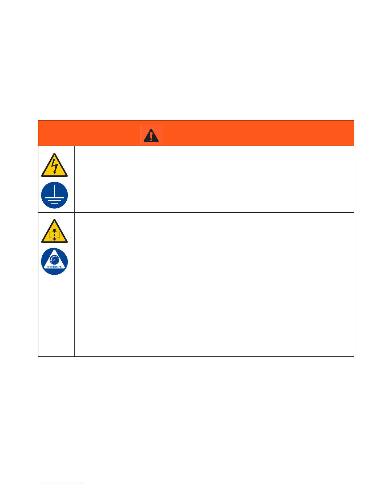
The following warnings are for the setup, use, grounding, maintenance, and repair of this equipment. The exclamation point symbol alerts you to a general warning and the hazard symbols refer to procedure-specific risks. When
these symbols appear in the body of this manual or on warning labels, refer back to these Warnings. Product-specific
hazard symbols and warnings not covered in this section may appear throughout the body of this manual where
applicable.
WARNING
ELECTRIC SHOCK HAZARD
This equipment must be grounded. Improper grounding, setup, or usage of the system can cause
electric shock.
• Turn off and disconnect power at main switch before disconnecting any cables and before servicing
or installing equipment.
• Connect only to grounded power source.
• All electrical wiring must be done by a qualified electrician and comply with all local codes and regulations.
EQUIPMENT MISUSE HAZARD
Misuse can cause death or serious injury.
• Do not operate the unit when fatigued or under the influence of drugs or alcohol.
• Do not exceed the maximum working pressure or temperature rating of the lowest rated system
component. See Technical Data in all equipment manuals.
• Use fluids and solvents that are compatible with equipment wetted parts. See Technical Data in all
equipment manuals. Read fluid and solvent manufacturer’s warnings. For complete information
about your material, request MSDS from distributor or retailer.
• Turn off all equipment and follow the Pressure Relief Procedure when equipment is not in use.
• Check equipment daily. Repair or replace worn or damaged parts immediately with genuine manufacturer’s replacement parts only.
• Do not alter or modify equipment. Alterations or modifications may void agency approvals and create safety hazards.
• Make sure all equipment is rated and approved for the environment in which you are using it.
• Use equipment only for its intended purpose. Call your distributor for information.
• Route hoses and cables away from traffic areas, sharp edges, moving parts, and hot surfaces.
• Do not kink or over bend hoses or use hoses to pull equipment.
• Keep children and animals away from work area.
• Comply with all applicable safety regulations.
332291G 5
Warnings
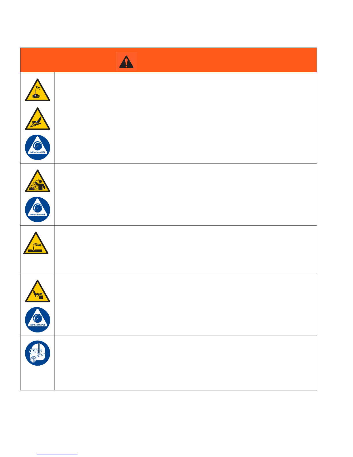
WARNING
SKIN INJECTION HAZARD
High-pressure fluid from dispensing device, hose leaks, or ruptured components will pierce skin. This
may look like just a cut, but it is a serious injury that can result in amputation. Get immediate surgi-
cal treatment.
• Do not point dispensing device at anyone or at any part of the body.
• Do not put your hand over the fluid outlet.
• Do not stop or deflect leaks with your hand, body, glove, or rag.
• Follow the Pressure Relief Procedure when you stop dispensing and before cleaning, checking,
or servicing equipment.
• Tighten all fluid connections before operating the equipment.
• Check hoses and couplings daily. Replace worn or damaged parts immediately.
PRESSURIZED EQUIPMENT HAZARD
Over-pressurization can result in equipment rupture and serious injury.
• A pressure relief valve is required at each pump outlet.
• Follow Pressure Relief Procedure in this manual before servicing.
PLASTIC PARTS CLEANING SOLVENT HAZARD
Many solvents can degrade plastic parts and cause them to fail, which could cause serious injury or
property damage.
• Use only compatible water-based solvents to clean plastic structural or pressure-containing parts.
• See Technical Data in this and all other equipment instruction manuals. Read fluid and solvent
manufacturer’s MSDSs and recommendations.
MOVING PARTS HAZARD
Moving parts can pinch, cut or amputate fingers and other body parts.
• Keep clear of moving parts.
• Do not operate equipment with protective guards or covers removed.
• Pressurized equipment can start without warning. Before checking, moving, or servicing equipment, follow the Pressure Relief Procedure and disconnect all power sources.
PERSONAL PROTECTIVE EQUIPMENT
Wear appropriate protective equipment when in the work area to help prevent serious injury, including eye injury, hearing loss, inhalation of toxic fumes, and burns. This protective equipment includes
but is not limited to:
• Protective eyewear, and hearing protection.
• Respirators, protective clothing, and gloves as recommended by the fluid and solvent manufacturer
6 332291G
Installation
A
D
H
B
E
J
F
I
G3-G-24NC-2L0A00-L0C00000
Grease Models with Follower
Plate
K
L
96GXXX
Oil Models
M
Grease Models
N
Auto-Fill Shut Off Models
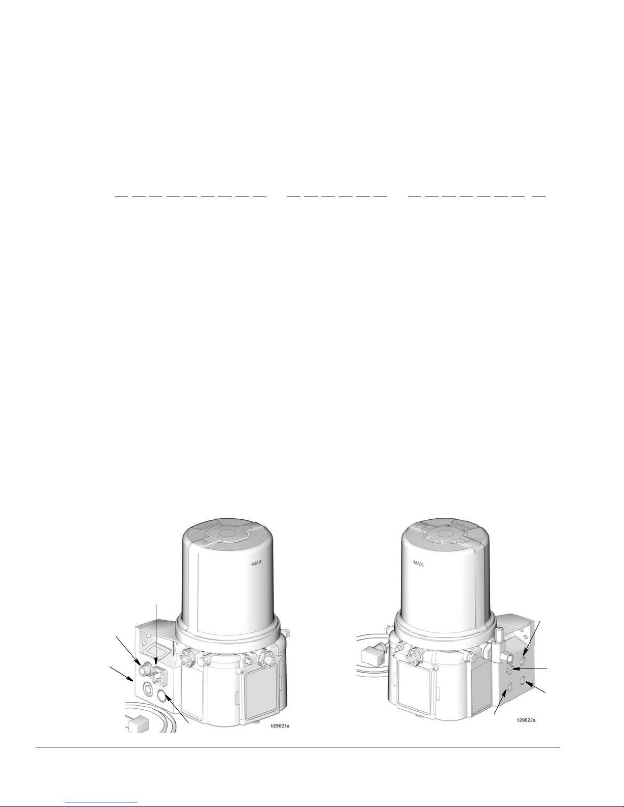
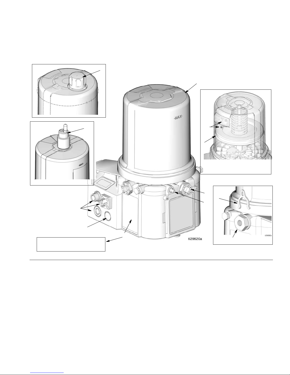
Component Identification
Installation
FIG. 2
Key:
AReservoir
B Adjustable Pump Element (1 included. Can accommodate 3
total)
C Pressure Relief Valve (Not included (not shown) / required for
each outlet - Available from Graco. See Parts, page 32.)
D Zerk Inlet Fill Fitting (1 included / grease models only)
E Pump Outlet Plug (2 included)
F Volume Control Spacers (2 included. More spacers = less
output volume per stroke) (also see F
G Fuse (DC models only - Not included, not shown. Available
from Graco. See Parts, page 32.)
H Power / Sensor Panel (both sides; only one side shown)
I Part Number / Model Number example only shown, (see
J Power Cord (DIN shown)
page 4, Understanding the Model Number, for details)
K Follower Plate (grease models only / not available on all
L Vent Hole for Follower Plate (grease models only / not
M Fill cap (oil models only)
N Auto-Fill Shut Off
IG. 18, page 19)
grease models)
available on all grease models)
332291G 7
Installation
A
B
D
E
F
C
A
B
D
E
F
H
G
C
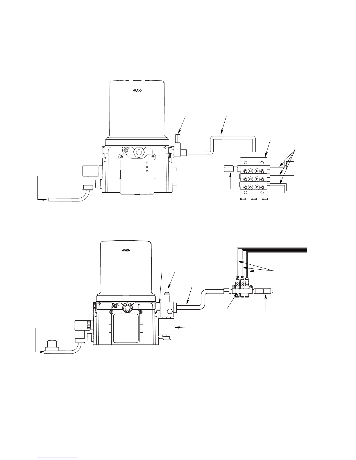
Typical Installation
Series Progressive Divider Valve
FIG. 3
Injector Installations
FIG. 4
Key
A Connected to fused power source
B Pressure relief valve (Not included/ required for each out-
let - user supplied. See Parts, page 32)
C Supply Hose (user supplied)
D Series progressive divider valves (Divider Installations)
- Injectors (Injector Installations)
8 332291G
E To lube points
F - Proximity Switch (Divider Installations)
- Pressure switch (Injector Installations)
G Vent valve (Not included / available from Graco. See
Parts, page 33.)
H Return to reservoir
Installation
E
D
C
F
P
N
K
H
J
M
L
A
R
Q
B
S
T
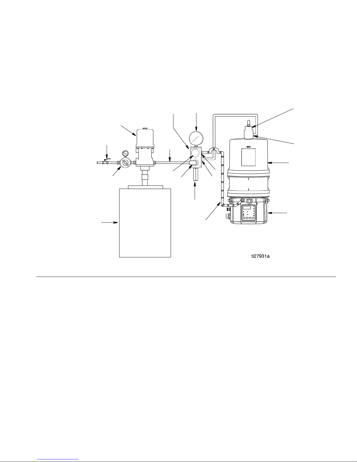
Typical Installation - With Remote Fill Manifold
The installation shown is only a guide for selecting and installing system components. Contact your Graco distributor
for assistance in planning a system to suit your needs.
FIG. 5
Key:
AG3 Pump
B Auto-Fill Shut Off Valve
C Auto-Fill Inlet
D G3 Reservoir
E Remote Fill Reservoir
F Remote Fill Pump
G Supply Hose (user supplied)
H Air Supply to Refill Pump
J Supply Hose (user supplied)
K Pressure Relief Valve
L Drain Hose
M Fill Coupler/Inlet (quick disconnect)
N Fill Manifold
P Fill Manifold Outlet
Q Fill Manifold Vent Port
R Pressure Gauge
S Pressure Regulator and Gauge
T Pressure Relief Knob
To relieve the stall pressure in the fill line a fill manifold
(N) must be installed in the system.
332291G 9
Installation
E
F
J
S
B
C
D
A
L1
H
U
V
L
L2
W
Y
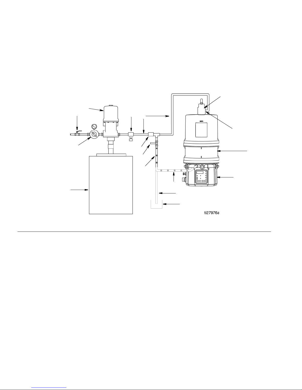
Optional Installation - Without Remote Fill Manifold
The installation shown is only a guide for selecting and installing system components. Contact your Graco distributor
for assistance in planning a system to suit your needs.
NOTE: The remote filling station pump stalls (dead-heads) when the reservoir is full. If the pump does not stall
(dead-head) there is a leak in the system.
FIG. 6
Key:
AG3 Pump
B Auto-Fill Shut Off Valve
C Auto-Fill Inlet
D G3 Reservoir
E Remote Fill Reservoir
F Remote Fill Pump
HRelief Valve
J Supply Hose (user supplied)
LDrain Tube
L1 Option - To reservoir
L2 Option - To overflow container
S Pressure Regulator and Gauge
U Pressure Relief Valve
V Quick Disconnect
W Overflow Container
Y Supply Hose Pressure Relief Valve
To relieve the stall pressure in the fill line a ball valve
(Y) must be installed in the system.
10 332291G
Choosing an Installation Location
AUTOMATIC SYSTEM ACTIVATION HAZARD
If the system is equipped with has an automatic timer
(user supplied) that activates the pump lubrication
system when power is connected or when exiting the
programming function, unexpected activation of the
system could result in serious injury, including skin
injection and amputation.
Before you install or remove the lubrication pump
from the system, disconnect and isolate all power
supplies and relieve all pressure.
• Select a location that will adequately support
the weight of the G3 Pump and lubricant, as
well as all plumbing and electrical connections.
• Refer to the mounting hole layouts provided in
the Mounting Pattern section of this manual,
page 35. No other installation configuration
should be used.
Installation
• Use designated mounting holes and provided
configurations only.
• Always mount the G3 oil models upright.
• If the G3 grease model is going to be operated
in a tilted or inverted position for any period of
time, you must use a model that includes a follower plate, otherwise the G3 must be mounted
upright. Refer to your model number to confirm
if a follower plate was installed on your pump.
See page 4, Understanding the Model Number
to identify this character in your model number.
• Use the three fasteners (included) to secure the
G3 to the mounting surface.
• Some installations may require an additional
reservoir support bracket. See Table below for
bracket information
Part No Description
571159 Reservoir bracket and strap
125910 L-Bracket for pump
127665 USP to G-Series mounting bracket
332291G 11
 Loading...