

Page 1
INSTRUCTIONS–P
This manual contains IMPORT
W
ARNINGS AND INSTRUCTIONS
READ AND RET
AIN FOR REFERENCE
ARTS LIST
ANT
Model G1200
HIGH EFFICIENCY
308–008
Rev D
Supersedes
C
LOW PRESSURE
HVLP
100
psi (7 bar) MAXIMUM WORKING FLUID PRESSURE
15 psi (1 bar) MAXIMUM WORKING AIR PRESSURE
See the Selection Chart on page 4 for complete spray
gun
assembly ordering numbers and descriptions.
Warnings 2.
Typical Installation 3.
Selection
Installation 7
Operation 8–9
Maintenance 10
Troubleshooting
Service 12–14
Air Flow 15.
Parts
Drawing
Parts List 17.
How
to Order Replacement Parts
Accessories 18–19
Technical
Warranty Back
SPRA
Y GUN
TABLE OF CONTENTS
. . . . . . . . . . . . . . . . . . . . . . . . . . . . . . . . . . . .
. . . . . . . . . . . . . . . . . . . . . . . . . . .
Charts
. . . . . . . . . . . . . . . . . . . . . . . . . . . . . . . . . . .
. . . . . . . . . . . . . . . . . . . . . . . . . . . . . . . . . . .
. . . . . . . . . . . . . . . . . . . . . . . . . . . . . . . . . . . .
. . . . . . . . . . . . . . . . . . . . . . . . . . . . . . . . . . .
Data
.
. . . . . . . . . . . . . . . . . . . . . . . . . . .
. . . . . . . . . . . . . . . . . . . . . . . . . . .
. . . . . . . . . . . . . . . . . . . . . . . . . . . . . . . . . . .
. . . . . . . . . . . . . . . . . . . . . . . . . . . . . . . . .
Chart
. . . . . . . . . . . . . . . . . . . . . . . . . . . . . . .
. . . . . . . . . . . . . . . . . . . . . . . . . . . . . .
.
. . . . . . . . . . . . . . . . . . . . . .
. . . . . . . . . . . . . . . . . . . . . .
. . . . . . . . . . . . .
Back Cover
Cover
4–6.
11.
16.
17.
GRACO INC. P.O. BOX 1441 MINNEAPOLIS, MN 55440–1441
COPYRIGHT
1990 GRACO INC.
Page 2

WARNINGS
FOR PROFESSIONAL USE ONLY. OBSERVE ALL WARNINGS.
Read and understand all instruction manuals, tags,
and warning labels before operating equipment.
EQUIPMENT MISUSE HAZARD
General
Any
as
chemicals and fluids, or using worn or damaged parts,
can cause them to rupture and result in serious bodily
injury,
NEVER point the spray gun at anyone or at any part of
the
zle.
ALWAYS
before
any
NEVER try to stop or deflect leaks with your hand or
body.
NEVER
so
CHECK all spray equipment regularly and repair or
replace
System Pressure
This gun has a
SURE
ING PRESSURE
maximum
ponent
Safety
misuse of the
over
pressurizing, modifying parts, using incompatible
fire, explosion or property damage.
body
. NEVER put hand or fingers over the spray noz
follow the
cleaning or removing
system equipment.
alter or modify any part of this equipment; doing
could cause it to malfunction.
worn or damaged parts immediately
spray equipment or accessories, such
Pressure Relief Procedure
the fluid nozzle or servicing
.
MAXIMUM FLUID WORKING PRES-
of 100 psi (7 bar) and a
of 15 psi (1 bar). Never exceed the
working pressure
or accessory used in the system.
MAXIMUM AIR WORK-
of the gun or any other com
, at
right,
Fluid Compatibility
BE SURE all fluids and solvents used are chemically
compatible
NICAL DATA on the back cover . Always read the fluid
and solvent manufacturer ’s literature before using the
fluid
Methylene
cleaning solvent with this gun or any other device with
nylon or
parts.
Pressure Relief Procedure
To reduce the risk of serious bodily injury , including
splashing
parts,
system,
system, when installing, cleaning or changing fluid nozzles,
1. T
2. Trigger the gun into a grounded metal waste con-
-
with the “W
or solvent in this gun.
Chloride
aluminum components as it can damage these
in the eyes or on the skin or injury from moving
always follow this procedure when shutting off the
when checking or servicing
and whenever you stop spraying.
urn of
f the air and fluid supply to the gun.
tainer
to relieve air and fluid pressure.
etted Parts” shown in the
is not recommended as a flushing or
any part of the spray
TECH-
HOSE SAFETY
TIGHTEN
NEVER use a damaged hose. Before each use, check
the
damage or movement of the hose couplings. If any of
these
all fluid connections securely before each use.
entire hose for cuts, leaks, abrasion, bulging cover
conditions exist, replace the hose immediately
, or
.
HANDLE AND ROUTE HOSES CAREFULL Y. Do not
on hoses to move equipment. Do not use fluids or sol
pull
vents which are not compatible with the inner tube and
cover
of the hose.
IMPORTANT
United
States Government safety standards have been adopted under the Occupational Safety and Health Act. These stan
dards––particularly the General Standards, Part 1910 and the Construction Standards, Part 1926––should be consulted.
-
-
Page 3
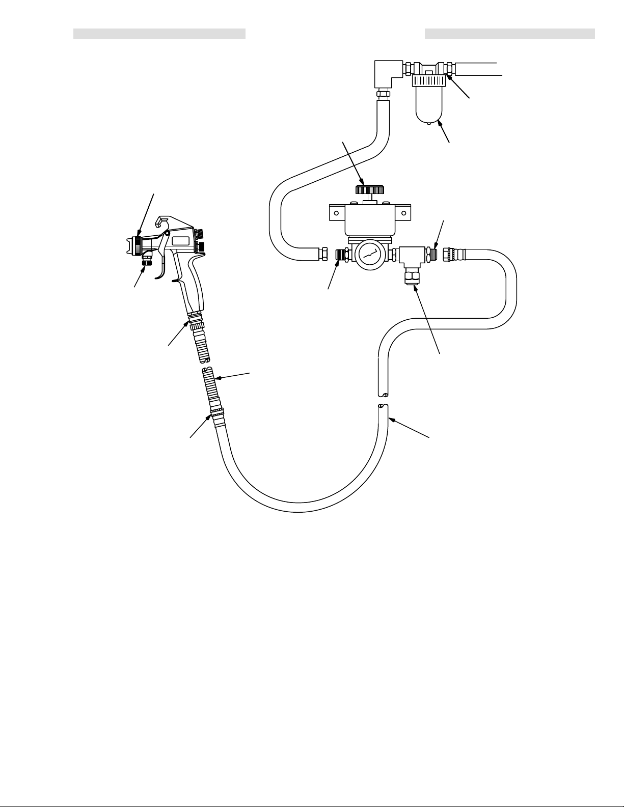
Fluid
Inlet
3/8 npsm
(R3/8–19)
MODEL G1200
SPRA
Y GUN
(See Chart, page 4)
TYPICAL INSTALLATION
1500
System
223–293
3/8 npt(m)
System air inlet
1/2 npt(f)
Filter inlet & outlet
Air
Filter 106–149
(See ACCESSORIES)
3/4–11.5 NH*
System air outlet
Quick-
Disconnect
Gun Air Hose
Connection
3/4–11.5 NH*
Swivel Fitting
*NH – standard garden hose fitting
Flexible
Hose
(See ACCESSORIES)
The Model G1200 High Efficiency Low Pressure Spray
Gun was designed to produce the highest quality finish
with
today’
organic
s fluids as well as the the Low V
compound)
fluids of tomorrow
.
.O.C.
(volatile
This spray gun can spray most coatings or finishes currently
being used
for automotive refinish, industrial, aero
space, marine, wood, plastic and architectural applications,
while easily operating from any paint delivery sys
tem, including pressure pots of any size, or remote
pumps
The
for production line operation.
Model G1200 Spray Gun
typically utilizes 10 psi (0.7
bar) air pressure with high air volume to produce high
quality
paint finishes.
One
air source is the High Ef
ficiency Low Pressure 1500
System. This system accurately converts standard air
Air Pressure Relief V
(Set at 15 psi [1.05 bar])
3/4”
ID Air Hose
(See ACCESSORIES)
line
pressure down to the 10 psi (0.7 bar) required to
all new regulations. Another air source is the High Efficiency Low pressure 8000 System. This system is a
stand-alone
plying
-
NOTE: Although
powered air supply
, which is
capable of sup
full, consistent air pressure to four guns.
the 1500 and 8000 Systems can have
an output air pressure of 15 psi (1.05 bar), for
-
Installation
operation,10 psi (0.7 bar) or lower output
proper
air
pressure is recommended.
of one of the Air Hose Assemblies listed in the
ACCESSORIES section is required to minimize the air
pressure drop in the hose while still maintaining good
hose flexibility. This combination produces the best
atomization
with high transfer ef
ficiency.
alve
meet
-
308-0083
Page 4
SELECTION
CHARTS
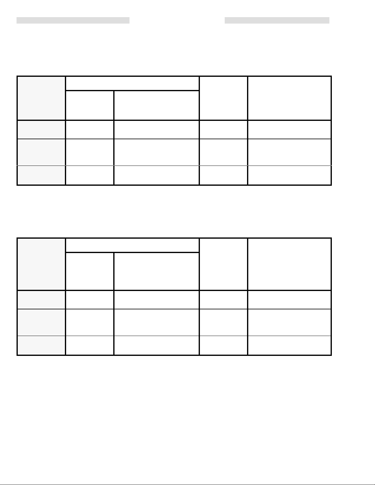
CHART 1: GUN ASSEMBLIES AVAILABLE
The following complete gun assemblies are
valves.
standard non-bleeder-type guns
Includes:
Complete
Gun Assy.
Part No.
223–252 223–300 223–232 0.055”
223–253 223–300 223–233 0.070”
223–254 223–300 223–234 0.086”
The
following complete gun assemblies are
Drawing
the
and List, pages 12 and 13). The bleeder-type gun allows air to bleed through the gun at all
trigger position.
Gun Body
Assy.
Part No.
Needle/Nozzle/Air Cap
Kit Part No.
bleeder-type guns
, which include the Air V
, with trigger-actuated air shut-of f
Orifice Size
(1.397 mm)
(1.778 mm)
(2.184 mm)
Material Usage
(See
TERMS below)
Light to Medium Fluids or
Low
Fluid
Flow (5–8 oz/min)
Medium to Heavy Fluids
or Medium
oz/min)
Heavy Fluids or Medium
Fluid
alve Filler 187–137 (see Parts
Fluid Flow (6–10
Flow (6–10 oz/min)
times, regardless of
Includes:
Complete
Bleeder
Gun Assy.
Part No.
224–609 224–606 223–232 0.055”
224–610 224–606 223–233 0.070”
224–611 224–606 223–234 0.086”
Gun Body
Assy.
Part No.
Needle/Nozzle/Air Cap
Kit Part No.
TERMS:
Light Fluid:
Medium Fluid:
Heavy Fluid:
15 to 20 seconds (No. 2 Zahn cup) -- Auto, Furniture, Appliances,
Fine Finish Metallics, T
20 to 25 seconds (No. 2 Zahn cup) -- Contact Adhesive, Latex, Maintenance
Paints, T
+25 seconds (No. 2 Zahn cup) -- 2.8 V
High-solid Polyurethanes, Heavy W
extures, Primers, Epoxies, V
op Coats, Lacquer
, Enamel Primer
inyls, High Flow High V
olatile Organic Compounds,
aterborne Enamels
Orifice Size
(1.397 mm)
(1.778 mm)
(2.184 mm)
.
iscosity.
Material Usage
(See
TERMS below)
Light to Medium Fluids or
Low
Fluid
Flow (5–8 oz/min)
Medium to Heavy Fluids
or Medium
oz/min)
Heavy Fluids or Medium
Fluid
Fluid Flow (6–10
Flow (6–10 oz/min)
4 308-008
Page 5
SELECTION
CHARTS
SELECTING THE PROPER NEEDLE/NOZZLE/AIR CAP SET
The High Efficiency Low Pressure Spray Gun’s needle/
nozzle sets range in size to provide dif ferent fluid flow
rates.
Chart 2 shows the recommended combinations of
needle/nozzle
Select
from Charts 2, 3, and 4, using the following
kits and air caps.
guide
lines.
As
a general guideline,
the
required flow with the needle fully triggered at the low
est
fluid pressure.
For low flow rates or light viscosity fluid,
smaller
For
nozzle
Some
one
nozzle sizes.
high flow rates or high viscosity fluid,
sizes.
applications may benefit by using an air cap that is
size larger then the needle/nozzle size that is being
used. In certain applications, this
use the fluid nozzle that will
select the
select the larger
may improve atomiza
give
tion, keep the air cap cleaner, and will decrease the pat
size. It will increase air flow
tern
pressure
at the air cap.
, but also
will decrease air
Using an air cap size that is smaller than the nozzle/
size
needle
is not
recommended.
NOTE: To help select the proper needle/nozzle size, a
fluid
pressure gauge may be connected
rarily to the gun fluid inlet to determine the fluid
pressure.
-
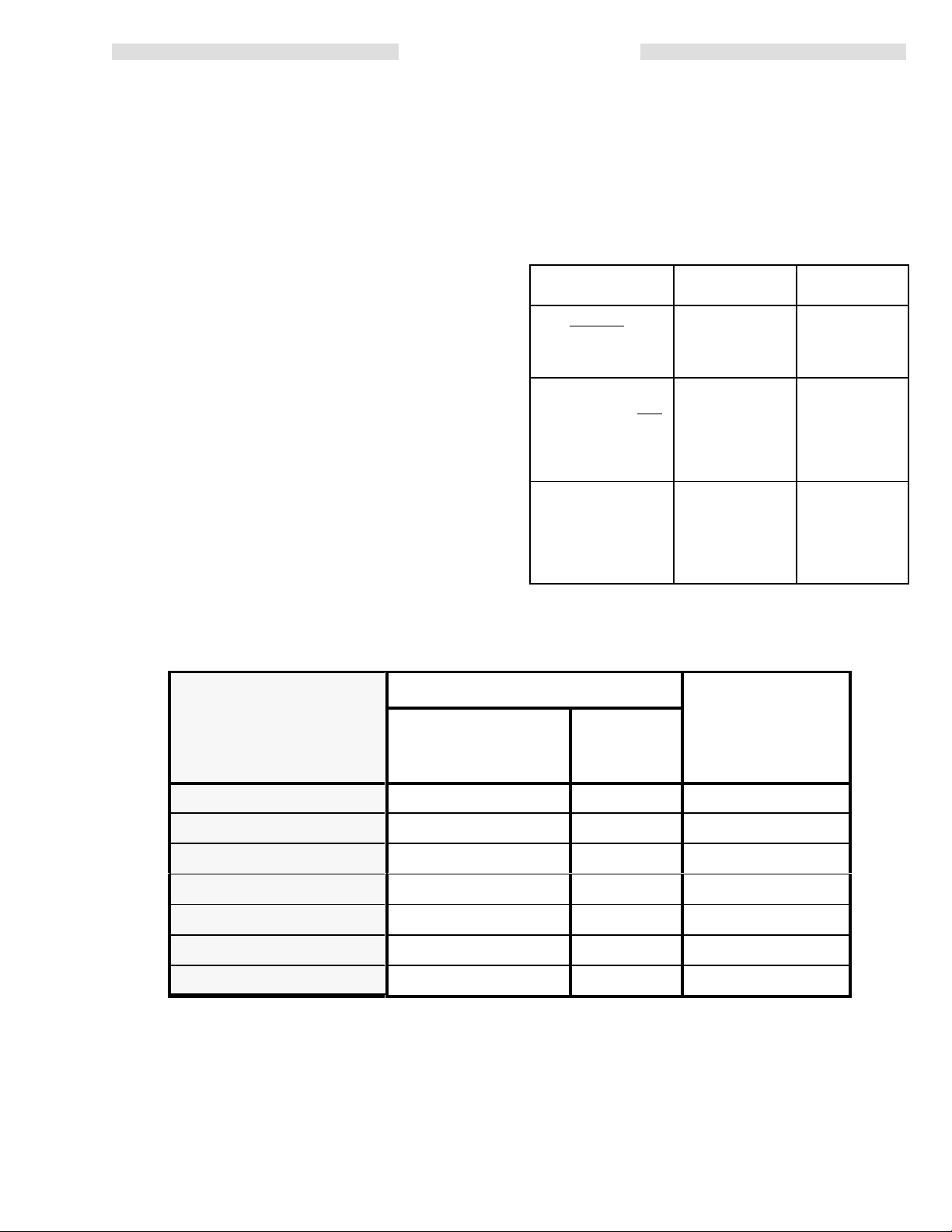
Selection Problems and Solutions
PROBLEM POSSIBLE
-
Fluid pressure
high (greater than 10
psi [0.7 bar]) with
gun triggered
Using a low pressure
setting, the fluid flow
is too high, making it
necessary to restrict
needle travel to
reduce fluid flow
-
-
Fluid system will not
operate at low
enough fluid pres
sure [below 10 psi
(0.7 bar)]
is too
.
-
CAUSE
Using set with too
small orifice
Using set with too
large orifice
There’
s no fluid
regulator or air
regulator is not
sensitive enough
SOLUTION
Use needle/
nozzle/air cap
set with larger
orifice
Use needle/
nozzle/air cap
set with smaller
orifice
Add low pres
sure fluid regu
lator or add
more sensitive
air regulator on
pressure pot
tempo
-
-
-
CHART 2: NEEDLE/NOZZLE/AIR CAP KIT
Includes:
Standard Plastic
Needle/Nozzle/Air Cap
Kit Part No.
223–230 223–240 185–720 0.030” (0.762 mm)
223–231 223–241 185–721 0.042” (1.067 mm)
223–232 223–242 185–722 0.055” (1.397 mm)
223–233 223–243 185–723 0.070” (1.778 mm)
223–234 223–244 185–724 0.086” (2.184 mm)
223–235 223–245 185–725 0.110” (2.794 mm)
223–236 223–246 185–726 0.125” (3.175 mm)
*Approximate fan width for all air cap sizes 9 to 12 in. (229 to 305 mm).
Needle & SST
Nozzle Kit Part No.
Air Cap*
Part No.
Charts
3 and 4 are on the next page.
Orifice Size
308-0085
Page 6

SELECTION
CHARTS
CHART 3: STANDARD NEEDLE/NOZZLE KIT
CHART 4:
OPTIONAL SST
MATCHED SET
Standard Plastic
Needle & SST
Nozzle Kit Part No.
223–240 185–700 185–710**
223–241 185–701 185–711
223–242 185–702 185–712
223–243 185–703 185–713
223–244 185–704 185–714
223–245 185–705 185–715
223–246 185–706 185–716
SST Fluid
Nozzle
Part No.
Includes:
Standard Plastic
Fluid Needle
Part No.
Orifice Size
0.030”
(0.762 mm)
0.042”
(1.067 mm)
0.055”
(1.397 mm)
0.070”
(1.778 mm)
0.086”
(2.184 mm)
0.110”
(2.794 mm)
0.125”
(3.175 mm)
Optional SST
Needle/Nozzle
Matched Set
Part No.
223–286
223–287
223–288
223–289
223–290
223–291
223–292
**Non-feathering
6 308-008
Page 7

Ventilate the Spray Booth
WARNING
To prevent hazardous concentrations of toxic
and/or
flammable vapors, spray only in a properly
ventilated
gun unless ventilation fans are operating.
Check and follow all of the National, State and
Local codes regarding air exhaust velocity
requirements.
Check
spray booth. Never operate the spray
and follow all local safety and fire codes.
Connect the Air Line
1. Connect
air hose and the gun’ s quick-disconnect air fitting.
Refer
the flexible air hose
to the System Drawing on page 3.
between the atomizing
INSTALLATION
2.
If using the High Efficiency Low Pressure Model
1500 Air Supply System,
separator (Part No. 106–149) on the air line to ensure
ture can ruin the appearance of your finished
workpiece.
Connect the Fluid Line
1. Before connecting the fluid line, blow it out with air
and flush it with solvent. Use solvent which is compatible
2. Install
pressure
3. Connect the fluid line to the gun fluid inlet (3/8–18
npsm
install an air and water
a dry
, clean air supply to the gun.
See ACCESSORIES.
with the fluid to be sprayed.
a fluid regulator on the fluid line to control fluid
to the gun.
[R 3/8–19] compound thread).
Dirt and mois
-
Air Cap
Fluid
Needle
Fluid
Nozzle
Fluid Inlet
Pattern Adjusting V
Fluid Adjusting Knob
alve
Fig 1
Air Inlet
308-0087
Page 8

OPERATION
WARNING
Pressure Relief Procedure
To
reduce the risk
splashing in the eyes or on the skin or injury from
moving parts, always follow this procedure when
shutting
any part of the spray system, when installing,
cleaning or changing fluid nozzles, and whenever
you
1. T
2. Trigger the gun into a grounded metal waste
of
f the system, when
stop spraying.
urn of
container
of serious bodily injury
checking or servicing
f the air and fluid supply to the gun.
to relieve fluid pressure.
, including
Filter the Fluid
Filter the fluid to remove coarse particles and sediment
which
could clog the spray nozzle.
Select a Needle/Nozzle Set and Air Cap
Check the viscosity of your paint. Install the proper
needle/nozzle
the
charts on pages 5 and 6.
Trigger the gun whenever you tighten or remove
the nozzle. This keeps the needle seat away from
the nozzle seating surface and prevents the seat
from
set and air cap combination, selected from
CAUTION
being scratched.
2. The
NOTE: The
3. Adjust
4. T
spray gun has a 15 psi (1 bar) maximum recom
mended inlet air pressure. Using the air pressure
regulator, set the air line pressure according to the
fluid
manufacturer’s recommendations for a high vol
ume,
low pressure application. Local laws may limit
the air line maximum pressure to 10 psi (0.7 bar).
H.E.L.P
(0.7
bar) air pressure with 100 psi (7 bar) air pres
sure at inlet. The pressure can be reduced by
adjusting
the pattern size by turning the pattern adjust
ing
valve
or
IN (clockwise)
o adjust the volume of fluid output:
a. Turn the fluid adjusting knob out
wise)
is
felt. Refer to Fig 1.
b. Then
or
pump until the desired fluid flow is obtained.
DO NOT
mum fluid pressure. Higher pressures can cause
parts
property
exceed the gun’ s 100 psi (7 bar) maxi-
to rupture and result in serious bodily injury
damage.
. 1500 System is factory set to 10 psi
the air supply adjustment knobs.
OUT (counterclockwise)
for a narrower pattern.
for a wider pattern
(counterclock-
until no restriction of the trigger
adjust the air pressure at the pressure
WARNING
movement
-
-
-
-
pot
or
Position the Air Cap
Rotate
the air cap as needed to achieve the desired spray
pattern direction. See Fig 2. T o create a round pattern,
turn
the pattern air of
Fig
2
f.
Vertical Pattern
Horizontal Pattern
Adjust the Spray Pattern
Follow these steps to establish the correct fluid flow
air
flow:
1. Adjust the fluid flow by using the fluid pressure
regulator
installed in the fluid line.
and
c. For
Restricting the trigger and fluid needle travel by
continuously
turned
sive wear on the fluid needle and wear on the trig
ger/air
For
sure pot or pump or use a dif ferent size needle/
nozzle set and air cap combination. See the
SELECTION
NOTE: If
d. The fluid flow can be feathered by partially trig-
5.
For continuous spraying,
valve in the full open position. This provides maximum
fluid
6. Test
the
test
final adjustment, turn the fluid adjusting
in
(clockwise)
put
and obtain the desired results.
in
(clockwise),
valve shaft interface.
the best results, adjust the fluid flow at the pres
the fluid adjusting valve is turned in all the way
the
gun will emit only air
gering the fluid needle, except when using the
smallest needle/nozzle/air cap size. See the
charts
on pages 5 and 6.
fluid flow and
nozzle.
the spray pattern and atomization while
gun about 6 to 8 inches (150 to 200 mm) from the
piece. Adjust as needed.
to reduce the volume of fluid out-
CAUTION
spraying
CHAR
with the fluid adjusting knob
will
cause accelerated abra
TS on pages 5 and 6.
.
leave the fluid adjusting
prevents premature wear on the
knob
-
-
-
holding
Page 9

OPERATION
Apply the Fluid
1. To
achieve the best
the
gun perpendicular to the surface and maintain a
consistent distance of approximately 6 to 8 inches
to 200 mm) from the object being sprayed. See
(150
Fig
3.
2. To obtain an even finish, use smooth, even strokes
across
the object being sprayed with 50% overlap.
3. Paint using parallel strokes. This spray gun applies
all
coatings evenly without cross coating.
results when applying fluid, keep
NOTE: To
at
110–367 in the gun’ s quick disconnect. See
ACCESSORIES.
If the one-way shut-of f valve is installed in the
gun
sure
of
eliminate the need to shut of
the air supply
line, allow for a 0.5 psi (0.035 bar) air
drop to the gun, due to increased restriction
the air line.
90
, install One-way Shut-of
6–8
in.
(150–200 mm)
f the air pressure
f V
pres
alve
-
Fig
WRONG RIGHT
3
Page 10

MAINTENANCE
Daily Care and Cleaning
WARNING
Pressure
To
reduce the risk
splashing in the eyes or on the skin or injury from
moving parts, always follow this procedure when
shutting
any part of the spray system, when installing,
cleaning or changing fluid nozzles, and whenever
you
1. T
2. Trigger the gun into a grounded metal waste
Clean all parts with a solvent compatible with the
fluid
parts.
Methylene
ing or cleaning solvent with this gun or any other
device
damage
To avoid getting solvent in the gun air passages,
NEVER
Relief Procedure
of serious bodily injury
of
f the system, when
stop spraying.
urn of
f the air and fluid supply to the gun.
container
being sprayed and compatible with gun wetted
See the Technical Data
with nylon or aluminum components as it can
to relieve fluid pressure.
CAUTION
Chloride
these parts.
immerse the gun in solvent.
is not recommended as a flush
checking or servicing
on the back page.
, including
3. Trigger the gun and remove the air cap and fluid
nozzle
from the gun. Soak them in solvent and scrub
them with the fine, bristled brush. See ACCESSO-
to order brush.
RIES
4. To
clean out air
as a toothpick, to avoid damaging critical surfaces.
Clean the air cap and fluid nozzle daily , minimum.
(Some
applications require more frequent cleaning.)
NOTE: If the fluid shaft is removed from the gun with
dried paint (fluid) still on the needle tip end,
replace
5. Lubricate
marked in Fig 4. Periodically lubricate the fluid
needle spring (16) with lubricant 1 11–265 (see ACCESSORIES to order).
-
cap holes, use a soft implement, such
the fluid seal as instructed on page 10.
the gun daily
, after cleaning it, at the points
Lubricate
Hold the front of the gun down when brushing it
clean
with solvent to prevent dirty solvent from get
into the air passages.
ting
1. After
2. Wipe the outside of the gun clean with a solvent
operation, flush the gun with a compatible sol
vent
until all traces of paint are removed from the gun
passages. Follow the Pressure Relief Procedure
Warning,
dampened
Trigger
nozzle. This keeps the needle seat away from the
nozzle seating surface and prevents the seat from
being
above, before proceeding.
cloth.
CAUTION
the gun whenever you tighten or remove the
scratched.
-
-
Lubricate
Fig 4
10 308-008
Page 11

TROUBLESHOOTING
WARNING
Pressure
To reduce the risk of serious bodily injury , including
splashing
ing
off
the system, when checking or servicing any part of
the
ing
PROBLEM CAUSE SOLUTION
Relief Procedure
in the eyes or on the
parts, always follow this procedure when shutting
spray system, when installing, cleaning or chang
fluid nozzles, and whenever you stop spraying.
skin or injury from mov
1. T
-
2. Trigger
-
CHART
urn of
f the air and fluid supply to the gun.
the gun into a grounded metal waste con
to relieve fluid pressure.
tainer
-
Whistling sound coming from gun
while
spraying
Fluid flow is fluttering while spraying
Fluid flow fades while spraying high
viscosity
No round pattern control
Pattern becomes of
on ends
fluids
f-set or heavy
Pattern valve vent hole position
1.
Fluid nozzle not tight enough
2.
Fluid filter clogged
3.
Fluid adjusting knob not
properly set
4. Baf
Fluid pressure too low, causing fluid
to stop or reduce when gun is
elevated
Baf
or damaged
1.
fle (item 1
or damaged
fle (item 1
Fluid nozzle is over tightened
1) installed wrong
1) installed wrong
Turn
pattern adjusting knob slightly
either
direction
1. Tighten fluid nozzle to 70–100
in-lbs (8–1
2.
Check fluid filter
3. Adjust
less feathering or use a larger
size
4. Check if baf fle protrusion is
properly inserted into gun insert
hole; see page 13. Replace
baffle
Raise
fluid pressure at source or use
a smaller fluid nozzle with higher air
pressure
Check if baffle protrusion is properly
inserted into gun insert hole; see
page
13. Replace baf
1. DO NOT exceed 70–100 in-lbs
(8–11 N m) torque. Replace
nozzle
1 N
m)
the fluid adjusting knob
nozzle
if damaged
on pressure pot
fle if damaged
if damaged
in
for
Fluid system will not operate at low
enough fluid pressure [below 10 psi
(0.7 bar)]
2.
Air cap too tight
3.
Air cap holes plugged
There’s
lator
no fluid regulator or air
is not sensitive enough
regu
2.
Loosen air cap
3. Clean air cap holes with non-
metallic
-
Add low pressure fluid regulator or
add more sensitive air regulator on
pressure
item such
pot
as a toothpick
308-00811
Page 12

Air Valve Service
When
the air valve is closed, a maximum of 0.5 scfm air
flow
is allowed to pass around the air valve during normal
operation. If an excessive amount of air is passing
through the air valve, service the valve as instructed
below; refer to Fig 7.
SERVICE
7h
1. Follow
NOTE:
the
Pressure Relief Procedure W
11 to relieve fluid pressure.
page
Removing the trigger will ease disassembly
arning
on
.
2. Remove the air cap ring (12), air cap (17), and fluid
nozzle (18).
3. Remove the fluid adjusting nut (8) and spring (16);
knob (9) will
the
spring (15),
guns only
come out with it. Remove the second
included with standard non-bleeder
.
4. Hold the fluid shaft (7b) while removing the fluid
needle (19). Pull the fluid shaft out the back of the
gun.
5. Push
the air valve (14) or air valve filler (25) out the
back of the gun.
6. Clean
the parts and check them for damage or wear
Replace
as necessary
.
NOTE: If dried paint is found on the fluid shaft (7b),
replace the fluid seal (7g) as instructed on
page 14.
Fig 5
4. Install the new air seal (14b) with its open end to the back of the gun body
wards
.
5. Align the flat on the cartridge (6) with the flat in the
gun
body
. See Fig 6.
6. Lightly lubricate the parts as indicated in Fig 7 and
.
reassemble
the gun.
0528
7. Lightly lubricate the fluid shaft (7b) and other parts
as indicated in Fig 7 with lubricant 1 11–265 (see
ACCESSORIES)
and reassemble the parts.
Air Valve Cartridge Removal
NOTE: The cartridge cannot be removed without dam-
aging the air seal (14b). Be sure to have a
replacement
1. Follow steps 1 through 4 in Air V alve Service ,
above.
2. Push
the air valve (14a) or air valve filler (25) out the
back
of the gun.
3. Place the packing removal tool (7h) through the
gun’s
trigger actuation area and against the air seal
(14b).
See Fig 5. Use a rubber mallet with the pack
removal tool to drive the cartridge (6) out the back
ing
of
the gun.
air seal.
FLAT
FLAT
6
Fig 6
-
0574
12 308-008
Page 13

12
Lightly
lubricate
SERVICE
T
17
orque to 70–100 in-lbs
(8–1
1 N
m).
18
19
T
orque to
30–40 in-lbs
Be sure protrusion is
properly inserted into
gun
insert hole before
tightening nozzle.
(3.4–4.5 N
5
m)
11
Flat
top of gun
U-cup spring
towards
front
of
gun
7g
7f
14b
3
Ref No. 14, Air V
7e
alve
Includes items 14a & 14b
U-cup spring
towards back
of gun.
with standard
6
25
Not included
non-bleeder
guns
NOTE:
Lubricate parts as indicated
in Fig 7 with lubricant 111–265. See
ACCESSORIES to order.
Optional
towards
Gun Plate
T
orque to
25–35 in-lbs
(2.8–4.0 N
13c
m)
Ref No. 7
Fluid Shaft Assembly
Includes items 7a–7i
14a
Lightly
lubricate
Lightly
lubricate
shaft
7c
7a
7b
7d
Fig
7
strength adhesive.
T
orque to 70–100 in-lbs
Apply low
(8–1
1 N
10
m).
Not included with
15
bleeder guns
16
Lightly
lubricate
T
orque to 25–35 in-lbs
(2.8–4.0 N
m).
8
Lightly
9
lubricate
0590
308-00813
Page 14

SERVICE
Fluid Seal Replacement
If
leakage occurs at the fluid seal area, the u-cup seal (7g)
or fluid shaft (7b) may be damaged or worn. Service as
instructed
NOTE: If the u-cup seal (7g) is removed, it MUST be
1. Follow
NOTE:
2. Remove the air cap ring (12), air cap (17), and fluid
3. Remove the fluid adjusting nut (8) and spring (16);
4. Hold the fluid shaft (7b) while removing the fluid
5. Insert
below; refer to Fig 7.
replaced.
the
Pressure Relief Procedure W
11 to relieve fluid pressure.
page
Removing the trigger will ease disassembly
arning
.
nozzle (18).
knob (9) will
the
spring (15),
guns only
come out with it. Remove the second
included with standard non-bleeder
.
needle (19). Pull the fluid shaft out the back of the
gun.
the
packing removal tool (7h) through the front
of the gun and push on the u-cup seal (7g) until
seal
and seal retainer (7f) are pressed out of the trig
ger
area. See Fig 8.
the
on
8. Install a new u-cup seal (7g) and seal retainer (7f)
into
the gun insert, following the procedure below
a. Carefully
er
diameter end of the seal insertion tool (7i), with
place the u-cup seal (7g) into the small
the open end of the seal facing outward in the
See Fig 9.
tool.
7i
7g
Fig 9
b. Make
sure the cavity for the seal is clean of dried
fluid. Place the seal insertion tool (7i) into the
back of the gun insert. See Fig 10. Then force
the seal down into the seal cavity , using the
packing
removal tool (7h).
7h
-
.
-
0531
7h
Fig 8
0533
6. To ease installation of the u-cup seal (7g), remove
the
trigger (3) and air valve (14) or air
valve filler (25).
7. Clean the parts. Check the fluid shaft (7b) for damage
or excessive wear
. Replace if necessary
. Lubri
cate the parts indicated in Fig 7 with lubricant
111–265.
7i
Fig 10
0532
c. Press the seal retainer (7f) in behind the u-cup
(7g) until a definite snap is felt.
seal
9.
Reassemble the remaining parts.
-
14 308-008
Page 15

AIR FLOW
STANDARD NON-BLEEDER GUNS
KEY
Fan
Open
Fan Closed
NOTE: T
standard 3/4” dia.,
25
1500
14
12
10
8
6
AIR FLOW (scfm)
4
2
0
02468101214
REGULATOR PRESSURE (psi)
ested with
ft (7.625
System
m) hose and
BLEEDER GUNS
KEY
Fan
Open
Fan Closed
NOTE: T
standard 3/4” dia.,
25
1500
14
12
10
8
6
AIR FLOW (scfm)
4
2
0
02468101214
REGULATOR PRESSURE (psi)
ested with
ft (7.625
System
m) hose and
308-00815
Page 16

17
18
19
PARTS
DRA
WING
12
4
11
**23
22**
3
Ref
No. 14,
Air V
alve
Includes items 14a & 14b
7g
7e*
7f
Optional,
replace item 2
5
2
21
to
Ref
No. 7
Fluid Shaft Assembly
Includes items 7a–7i
13e
13d*
13
13c
13b*
13a
14b*
6
14a*
7a
7c
7b
Not included
25
with standard
1
non-bleeder
guns
7d*
16 308-008
10
24
Not
included with
bleeder guns
15
16
8
9
Page 17

PARTS LIST
PTFE
Standard Non-bleeder Guns
Part
Nos. 223–252, 223–253, 223–254
Includes items 1–24
REF
NO. P
1 223–306
2 275–852 HOOK 1
3 185–761
4 185–746
5 203–953 SCREW
6 185–751 CAR
7 223–302
7a 224–849 S
7b SSSHAFT
7c
7d* 110–404 SS
7e* 223–304 S
7f 275–847 SSRET
7g 110–400 SS
7h 179–803 SST
7i 187–349 SST
8 185–744 NUT
9 185–745
10 185–772
11 275–851
12 185–759
13 223–301 VAL
ART NO.
DESCRIPTION QTY
GUN BODY
TRIGGER, two-finger
PIN, pivot; 10-24 UNC-2B
, lock; No. 10–24 UNC-2A
x 0.375 in.
TRIDGE, valve
SHAFT ASSEMBLY, fluid
Includes items 7a–7i
SHAFT RING Assembly
Includes items 7b–7d
, fluid;
cannot order
separately
{SS
RING, retaining;
separately
RING, grip
FLUID SEAL Assembly
Includes items 7f–7i
AINER, seal; Delrin
SEAL, u-cup; carbon graphite
filled
r 1
OOL, packing removal
OOL, seal insertion
, fluid adjusting
KNOB, fluid adjusting
FITTING, air inlet
BAFFLE, pattern
RING, air cap
VE ASSEMBLY, pattern
Includes items 13a–13e
1
cannot order
r 1
Bleeder Guns
Part
Nos. 224–609, 224–610, 224–61
Includes items 1–13, 14b, 16–25
REF
NO. P
13a 185–748 SSCREW
13b* 168–110 S
1
13c 185–747 SNUT
13d* 105–456 S
1
13e 275–850 SVAL
1
14 223–303 VAL
1
14a 223–305 SVAL
1
14b* 110–405 S
1
15 110–401
1
16 110–402
1
1
17
1
18
1
19
21 275–853 PLA
1
1
22** 185–758
23** 106–456
1
1
24 110–365
1
25 187–137
1
1
*Recommended “tool box” replacement parts.
1
**Not intended to be removed.
ART NO.
DESCRIPTION QTY
, air adjustment
O-RING; V
itonr 1
, air adjusting
RING, retaining
VE, pattern
VE, air;
Includes items 14a & 14b
VE, shuttle;
guns only
SEAL, u-cup; carbon/graphite
filled PTFE
SPRING, compression
non-bleeder
SPRING, compression;
AIR CAP; See charts on
pages 4–6
FLUID NOZZLE; See charts on
pages 4–6
FLUID NEEDLE; See charts on
pages 4–6
TE, gun;
(T
o replace hook, item 2)
FITTING, fluid
O-RING; V
iton 1
FITTING, quick-disconnect
FILLER, air valve;
bleeder
guns only
1
non-bleeder
guns only
1
1
1
1
1
1
1
1
1
1
1
1
1
1
1
1
HOW T
1. To be sure you receive the correct replacement parts, kits or
accessories, always give all of the information requested in the
chart
2. Check
the
ref. no. when ordering.
3.
Order all parts from your nearest Graco distributor
6 digit
Part
Number Qty
O ORDER REPLACEMENT P
below
.
the parts list to identify the correct
Part Description
ARTS
part number; do not use
.
{
Requires
factory tooling to install.
SERVICE INFORMATION
Added
Seal Insertion T
Seal Assembly . Added Bleeder Gun Models to the
manual.
Also completed a general
drawings.
ool 187–349 (item 7i) to the Fluid
update of the text and
308-00817
Page 18

ACCESSORIES
H.E.L.P. AIR REGULATOR & GUN SYSTEMS
Wall-Mount
H.E.L.P.
System
Part No.
224–074
224–075
224–076
224–078
224–079
224–080
*
Includes 25 ft (7.625 m) Atomizing Air Hose Assembly 223–265 and
5 ft (1.525 m) Flexible Air Hose Assembly 223–296.
Wall-Mount
& Pressure Cup System
H.E.L.P.
System
Part No.
224–089
Air Regulator & Gun System
G1200
Spray Gun
Part No.
223–251 0.042”
223–252 0.055”
223–253 0.070”
223–251 0.042”
223–252 0.055”
223–253 0.070”
Air Regulator
G1200 Gun
with Cup
Part No.
223–272 0.055”
Orifice
Size
(1.1
mm)
(1.4 mm)
(1.8 mm)
(1.1 mm)
(1.4 mm)
(1.8 mm)
, Gun
Orifice
Size
(1.4
mm)
Air Hose
Part No.
223–265
25’ (7.6 m)
223–265
25’ (7.6 m)
223–265
25’ (7.6 m)
223–274*
30’ (9.2 m)
223–274*
30’ (9.2 m)
223–274*
30’ (9.2 m)
Air Hose
Part No.
223–274*
30’ (9.2 m)
H.E.L.P.
1500 System
Part No.
223–293
wall-mount
223–293
wall-mount
223–293
wall-mount
223–293
wall-mount
223–293
wall-mount
223–293
wall-mount
H.E.L.P.
1500 System
Part No.
223–293
wall-mount
FOUR-FINGER TRIGGER CONVERSION
KIT 185–762
For
changing from a standard two-finger trigger to a four-
finger trigger.
AIR PRESSURE VERIFICATION
KIT 224–119
For
use in checking gun inlet air pressure at various sup
air pressures.
ply
Assemble
the
quick-disconnect air fitting in the gun air inlet. T
the kit as shown in the drawing below
the air to the gun, then trigger the gun and read the resulting
air pressure.
NOTE: To be “HVLP compliant”, the atomizing inlet air
pressure
The air cap pressure will be slightly lower than the inlet
air pressure reading [approximately 0.5 psi (0.3 bar)]
to the natural pressure drop in the gun air passages
due
Gauge accuracy is +/– 2% over the middle half of the
gauge scale, +/– 3% over the remainder of the gauge
scale.
NOT to be used
for actual spraying.
. Install
urn on
must not exceed 10 psi (0.7 bar).
-
*
Includes 25 ft (7.625 m) Atomizing Air Hose Assembly 223–265 and
5 ft (1.525 m) Flexible Air Hose Assembly 223–296.
Belt-Mount
H.E.L.P.
System
Part No.
224–084
224–085
224–086
Belt-Mount
Air Regulator & Gun System
G1200
Spray Gun
Part No.
223–251 0.042”
223–252 0.055”
223–253 0.070”
Orifice
(1.1
(1.4 mm)
(1.8 mm)
Air Regulator
Size
mm)
, Gun
Flex
Air Hose
Part No.
223–296
5’ (1.5 m)
223–296
5’ (1.5 m)
223–296
5’ (1.5 m)
H.E.L.P
1500 System
Part No.
223–285
belt-mount
223–285
belt-mount
223–285
belt-mount
& Pressure Cup System
H.E.L.P.
System
Part No.
224–083
G1200 Gun
with Cup
Part No.
223–272 0.055”
Orifice
(1.4
Size
mm)
Flex
Air Hose
Part No.
223–296
5’ (1.5 m)
H.E.L.P.
1500 System
Part No.
223–285
belt-mount
CLEANING BRUSH 105–749
For
use in cleaning gun
PRESSURE CUP with Cover 214–627
2
qt (1.94 liter) capacity
, aluminum body
Includes air pressure regulator and gauge, 4 ft (1.2 m)
.
length air and fluid hose with 1/4 npsm(f) swivel ends,
safety
relief valve, and rigid hook handle.
PRESSURE CUP with Cover 223–270
1
qt (0.95 liter) capacity
Some assembly required. To connect the supply air to
the pressure cup, you must replace the air inlet fitting
supplied with the gun with air inlet fitting 185–760
(supplied
with the pressure cup).
, aluminum body
.
LUBRICANT 111–265
One 4 oz. (113 gr) tube sanitary (non-silicone) lubricant
for
fluid packings and wear areas.
18 308-008
Page 19

ACCESSORIES
Circulating
Adapters
Coupler Stems
3/8 npsm
Stainless Steel
Gun Mounted
Fluid Regulators
Straight Adapters
3/8 npsm
1/4 npsm
Twist Lock
Models
Models
Models
Models
*
Stainless Steel Models
These
208–087*
223–627*
1.0
oz
223–621*
7.0 oz
214–018
223–624*
214–019
223–626*
Models are compatable with water-base fluids
Slip Ring
Union
Twist Lock
Adapter
208–085*
1.5 oz
208–082*
7.5 oz
208–250 223–625*
208–252 210–097
223–622*
7.0 oz
204–891*
223–628*
1.3 oz
223–623*
7.3 oz
FLUID HOSE ASSEMBLY 205–142
300
psi (21 bar) MAXIMUM WORKING PRESSURE
Nylon with neoprene cover , 0.375 in. (9.5 mm) ID,
3/8 npsm(fbe),
25 ft (7.6 m) long
FLEXIBLE AIR HOSE ASSEMBLY
15
psi (1 bar) MAXIMUM WORKING PRESSURE
0.62
in. (16 mm) ID, 3/4–1
female swivel fitting
thread
(to gun quick-disconnect).
movement
of the spray gun.
223–295
223–296
3 ft (0.912 m) long
5 ft (1.525 m) long
1.5 NH (standard garden hose)
(to air hose
) and 3/4–1 1.5 male
Install for more flexible
ATOMIZING AIR HOSE ASSEMBLY
15
psi (1 bar) MAXIMUM WORKING PRESSURE
0.75
in. (19 mm) ID, 3/4–1
male
x female swivel fittings, natural-color
223–263 15
223–265
25 ft (7.625 m) long
1.5 NH (standard garden hose)
polyurethane
ft (4.575 m) long
AIR HOSE COUPLING WASHER 110–366
Replacement
hose.
washer for use in
female swivel end of air
FILLER AIR VALVE 187–137
Replaces
air valve and converts the gun to a bleeder gun.
ONE-WAY AIR SHUT-OFF VALVE 110–367
Install in standard quick disconnect (provided with flexible
air hose assy
is
disconnected.
.) to turn of
f air pressure when spray gun
AIR HOSE QUICK-DISCONNECT 110–365
Install
between gun air inlet fitting and air hose.
TWIN OUTPUT AIR ADAPTER 111–222
Allows
output of air to two guns from
a H.E.L.P
. 1500 System.
AIR FILTER & MOISTURE
SEPARATOR 106–149
250 psi (17.5 bar) MAXIMUM WORKING PRESSURE
Removes
compressed
moisture, oil, and other contaminants from the
air supply
. 1/2 npt(fbe)
308-00819
Page 20

TECHNICAL
DA
TA
IMPORTANT
PHONE NUMBERS
Weight 17
Gun
Maximum Working Fluid Pressure
Maximum Working Air Pressure
Air
Fluid
Wetted
Delrin
.
. . . . . . . . . . . . . . . . . . . . . . . . . . . .
Length
Inlet
Inlet
WARRANTY
Graco
on
of
proven
Graco’s
This
misapplication,
of
Graco
facture,
This
tributor
defective
ment
may
.
. . . . . . . . . . . . . . . . . . . . .
.
. . . .
.
. . . . . . .
3/4–1
.
. . . . . . .
3/8–18 npsm (R3/8–19) compound thrd.
.
. .
Parts
is a registered trademark of Company
the date of sale by an authorized Graco distributor to the original purchaser for use. As purchaser’s sole remedy for breach
this warranty
warranty does not cover
non–Graco component parts. Nor shall Graco be liable for malfunction, damage or wear caused by the incompatibility with
warranty is conditioned upon the prepaid
include the costs of parts, labor and transportation.
. . . . .
warrants all equipment manufactured by it and bearing
defective. This warranty
written recommendations.
equipment of structures, accessories, equipment or materials not supplied by Graco, or the improper design, manu
installation, operation or maintenance of structures, accessories, equipment or materials not supplied by Graco.
for verification of the claimed defect. If the claimed defect is verified, Graco will repair or replace free of charge any
parts. The equipment will be returned to the original purchaser transportation prepaid. If inspection of the equip
does not disclose any defect in material or workmanship, repairs will be made at a reasonable charge, which charges
1.5 NH (standard garden hose)
304 Stainless Steel, Delrin
THE
GRACO W
, Graco will, for a
abrasion, corrosion, inadequate or improper maintenance, negligence, accident, tampering, or substitution
period of twelve months from the date of sale, repair or replace any part of the equipment
applies only when the equipment is installed, operated and maintained in accordance with
, and Graco shall not be liable for, any malfunction, damage or wear caused by faulty installation,
oz. (475 g)
6.39 in. (163 mm)
100 psi (7 bar)
15 psi (1 bar)
.
ARRANTY AND DISCLAIMERS
return of the equipment claimed to be defective to an authorized Graco dis
TO
PLACE AN ORDER
, contact your Graco distributor
or call this number to identify the distributor closest to
you:
FOR TECHNICAL ASSISTANCE
mation
or assistance regarding the application of Graco
equipment:
1–800–328–0211 T
1–800–543–0339 T
oll Free
, service repair infor-
oll Free
.
its name to be free from defects in material and workmanship
,
-
-
-
DISCLAIMERS AND LIMITATIONS
TERMS OF THIS W
THE
OF ANY OTHER W
RANTY
PRODUCT
SPECIAL
GRACO’S
MUST BE BROUGHT WITHIN TWO (2) YEARS OF THE DATE OF SALE.
EQUIPMENT NOT COVERED BY GRACO WARRANTY
GRACO
TICULAR
FACTURED
subject
claim
OF FITNESS FOR A PARTICULAR PURPOSE, AND OF ANY NON–CONTRACTUAL LIABILITIES, INCLUDING
LIABILITIES, BASED ON NEGLIGENCE OR STRICT LIABILITY
OR CONSEQUENTIAL DAMAGES OR LOSS IS EXPRESSL
LIABILITY EXCEED THE AMOUNT OF THE PURCHASE
MAKES NO W
PURPOSE, WITH RESPECT T
BY GRACO.
to the warranty
for breach of these warranties.
ARRANTY CONSTITUTE PURCHASER’S SOLE AND EXCLUSIVE REMEDY AND ARE IN LIEU
ARRANTIES (EXPRESS OR IMPLIED), INCLUDING W
Y EXCLUDED AND DENIED. IN NO CASE SHALL
PRICE. ANY ACTION FOR BREACH OF W
ARRANTY
These items sold, but not
, if any
, AND DISCLAIMS ALL IMPLIED W
O ACCESSORIES, EQUIPMENT
, of their manufacturer
manufactured by Graco (such as electric motor
. Graco will provide purchaser with reasonable assistance in making any
ARRANTIES
, MA
TERIALS, OR COMPONENTS SOLD BUT NOT MANU
ARRANTY OF MERCHANT
. EVER
Y FORM OF LIABILITY FOR DIRECT
OF MERCHANT
ABILITY AND FITNESS FOR A P
, switches, hose, etc.) are
ABILITY OR W
ARRANTY
AR-
,
AR-
-
Factory
Branches:
Atlanta, Chicago, Dallas, Detroit, Los Angeles, W
Subsidiary and Affiliate Companies:
GRACO INC.P.O. BOX 1441
est Caldwell (N.J.)
Canada; England; Switzerland; France; Germany; Hong Kong; Japan;
Korea
PRINTED
MINNEAPOLIS, MN
IN U.S.A. 308–008 3/90 Revised 7/91
55440–1441
 Loading...