

Page 1
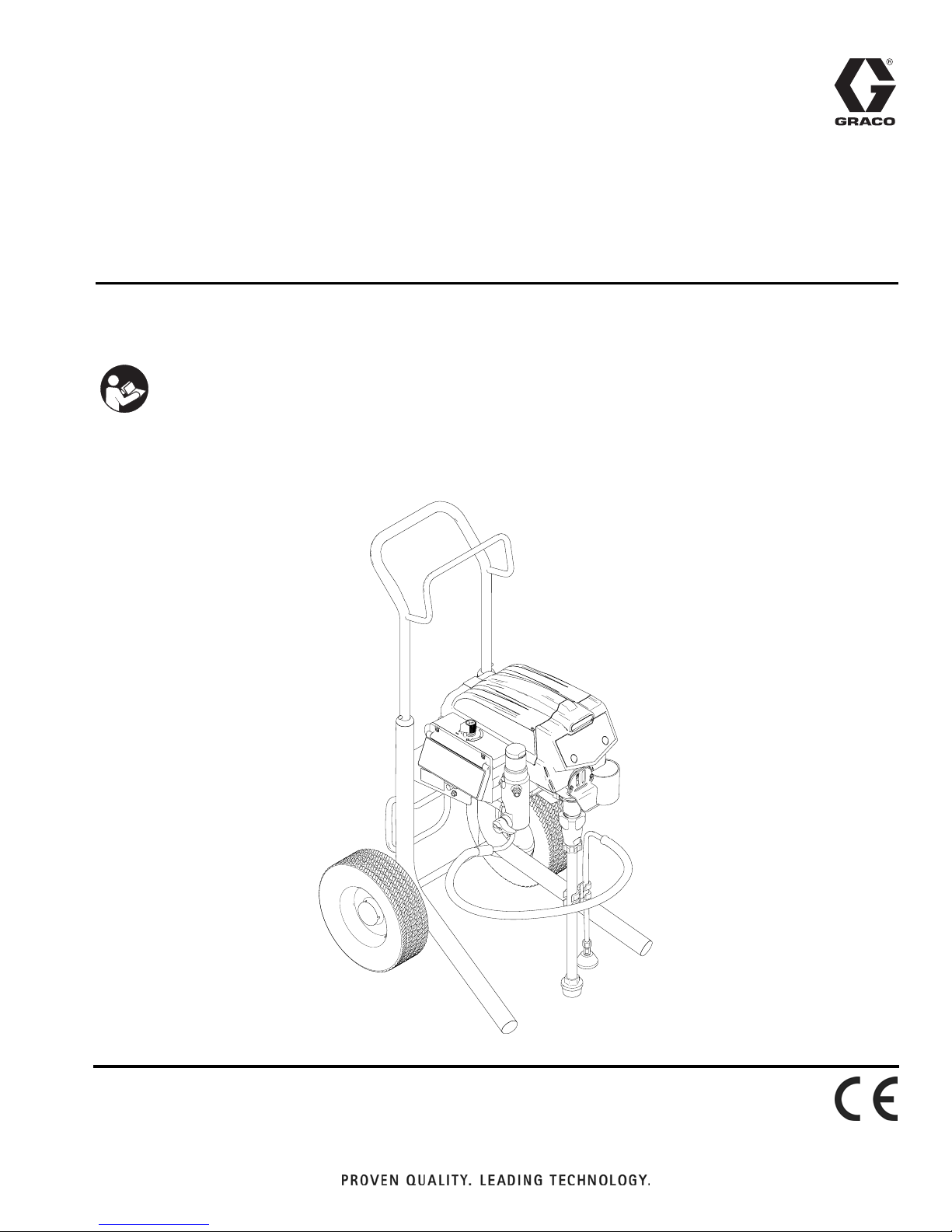
Operation
FT600 Electric Airless Sprayer
- For the application of architectural paints and coatings -
- For professional use only -
IMPORTANT SAFETY INSTRUCTIONS
Read all warnings and instructions in this
manual. Save these instructions.
Model 278680
3300 psi (227 bar, 22.7 MPa) Maximum Working Pressure
332255A
EN
ti21026a
Page 2

Contents
Contents
Warnings . . . . . . . . . . . . . . . . . . . . . . . . . . . . . . . . . 3
Component Identification . . . . . . . . . . . . . . . . . . . . 5
Grounding . . . . . . . . . . . . . . . . . . . . . . . . . . . . . . . . 6
Power Requirements . . . . . . . . . . . . . . . . . . . . . 6
Extension Cords . . . . . . . . . . . . . . . . . . . . . . . . . 6
Pails . . . . . . . . . . . . . . . . . . . . . . . . . . . . . . . . . . 7
Pressure Relief Procedure . . . . . . . . . . . . . . . . . . . 8
Setup . . . . . . . . . . . . . . . . . . . . . . . . . . . . . . . . . . . . 9
Startup . . . . . . . . . . . . . . . . . . . . . . . . . . . . . . . . . . 10
Tip and Guard Assembly . . . . . . . . . . . . . . . . . . . 11
Spraying . . . . . . . . . . . . . . . . . . . . . . . . . . . . . . . . . 11
Clearing Clog . . . . . . . . . . . . . . . . . . . . . . . . . . . . . 12
Cleanup . . . . . . . . . . . . . . . . . . . . . . . . . . . . . . . . . 13
Digital Display . . . . . . . . . . . . . . . . . . . . . . . . . . . . 15
Main Menu Operation . . . . . . . . . . . . . . . . . . . . 16
Secondary Menu . . . . . . . . . . . . . . . . . . . . . . . 16
Change Display Units . . . . . . . . . . . . . . . . . . . . 16
Technical Data . . . . . . . . . . . . . . . . . . . . . . . . . . . . 17
Graco Standard Warranty . . . . . . . . . . . . . . . . . . . 18
2 332255A
Page 3
Warnings
Warnings
The following warnings are for the setup, use, grounding, maintenance, and repair of this equipment. The exclamation point
symbol alerts you to a general warning and the hazard symbols refer to procedure-specific risks. When these symbols
appear in the body of this manual or on warning labels, refer back to these Warnings. Product-specific hazard symbols and
warnings not covered in this section may appear throughout the body of this manual where applicable.
WARNING
WARNINGWARNINGWARNING
FIRE AND EXPLOSION HAZARD
Flammable fumes, such as solvent and paint fumes, in work area can ignite or explode. To help prevent fire
and explosion:
• Do not spray flammable or combustible materials near an open flame or sources of ignition such as cigarettes, motors, and electrical equipment.
• Paint or solvent flowing through the equipment is able to result in static electricity. Static electricity creates
a risk of fire or explosion in the presence of paint or solvent fumes. All parts of the spray system, including
the pump, hose assembly, spray gun, and objects in and around the spray area shall be properly
grounded to protect against static discharge and sparks. Use Graco conductive or grounded high-pressure airless paint sprayer hoses.
• Verify that all containers and collection systems are grounded to prevent static discharge. Do not use pail
liners unless they are are antistatic or conductive.
• Connect to a grounded outlet and use grounded extensions cords. Do not use a 3-to-2 adapter.
• Do not use a paint or a solvent containing halogenated hydrocarbons.
• Keep spray area well-ventilated. Keep a good supply of fresh air moving through the area. Keep pump
assembly in a well ventilated area. Do not spray pump assembly.
• Do not smoke in the spray area.
• Do not operate light switches, engines, or similar spark producing products in the spray area.
• Keep area clean and free of paint or solvent containers, rags, and other flammable materials.
• Know the contents of the paints and solvents being sprayed. Read all Material Safety Data Sheets
(MSDS) and container labels provided with the paints and solvents. Follow the paint and solvents manufacturer’s safety instructions.
• Fire extinguisher equipment shall be present and working.
• Sprayer generates sparks. When flammable liquid is used in or near the sprayer or for flushing or cleaning, keep sprayer at least 20 feet (6 m) away from explosive vapors.
ELECTRIC SHOCK HAZARD
This equipment must be grounded. Improper grounding, setup, or usage of the system can cause electric
shock.
• Turn off and disconnect power cord before servicing equipment.
• Connect only to grounded electrical outlets.
• Use only 3-wire extension cords.
• Ensure ground prongs are intact on power and extension cords.
• Do not expose to rain. Store indoors
• Wait five minutes after disconnecting power cord before servicing large capacitor units.
332255A 3
Page 4
Warnings
WARNING
WARNINGWARNINGWARNING
SKIN INJECTION HAZARD
High-pressure fluid from gun, hose leaks, or ruptured components will pierce skin. This may look like just a cut, but it is a
serious injury that can result in amputation. Get immediate surgical treatment.
•
Do not spray without tip guard and trigger guard installed.
•
Engage trigger lock when not spraying.
•
Do not point gun at anyone or at any part of the body.
•
Do not put your hand over the spray tip.
•
Do not stop or deflect leaks with your hand, body, glove, or rag.
•
Follow the Pressure Relief Procedure when you stop spraying and before cleaning, checking, or servicing equip-
ment.
•
Tighten all fluid connections before operating the equipment.
•
Check hoses and couplings daily. Replace worn or damaged parts immediately.
EQUIPMENT MISUSE HAZAR
Misuse can cause death or serious injury.
•
Do not operate the unit when fatigued or under the influence of drugs or alcohol.
•
Do not exceed the maximum working pressure or temperature rating of the lowest rated system component. See
Technical Data in all equipment manuals.
•
Use fluid and solvents that are compatible with equipment wetted parts. See Technical Data in all equipment manuals. Read fluid and solvent manufacturer’s warnings. For complete information about your material, request MSDS
from distributor or retailer.
•
Do not leave the work area while equipment is energized or under pressure.
•
Turn off all equipment and follow the Pressure Relief Procedure when equipment is not in use.
•
Check equipment daily. Repair or replace worn or damaged parts immediately with genuine manufacturer’s replacement parts only.
•
Do not alter or modify equipment. Alterations or modifications may void agency approvals and create safety hazards.
•
Make sure all equipment is rated and approved for the environment in which you are using it.
•
Use equipment only for its intended purpose. Call your distributor for information.
•
Route hoses and cables away from traffic areas, sharp edges, moving parts, and hot surfaces.
•
Do not kink or over bend hoses or use hoses to pull equipment.
•
Keep children and animals away from work area.
•
Comply with all applicable safety regulations.
PRESSURIZED ALUMINUM PARTS HAZARD
Use of fluids that are incompatible with aluminum in pressurized equipment can cause serious chemical reaction and
equipment rupture. Failure to follow this warning can result in death, serious injury, or property damage.
•
Do not use 1,1,1-trichloroethane, methylene chloride, other halogenated hydrocarbon solvents or fluids containing
such solvents.
•
Many other fluids may contain chemicals that can react with aluminum. Contact your material supplier for
compatibility.
TOXIC FLUID OR FUMES HAZARD
Toxic fluids or fumes can cause serious injury or death if splashed in the eyes or on skin, inhaled, or swallowed.
•
Read MSDSs to know the specific hazards of the fluids you are using.
•
Store hazardous fluid in approved containers, and dispose of it according to applicable guidelines.
PERSONAL PROTECTIVE EQUIPMENT
Wear appropriate protective equipment when in the work area to help prevent serious injury, including eye injury, hearing
loss, inhalation of toxic fumes, and burns. This protective equipment includes but is not limited to:
•
Protective eyewear, and hearing protection.
•
Respirators, protective clothing, and gloves as recommended by the fluid and solvent manufacturer.
4 332255A
Page 5
Component Identification
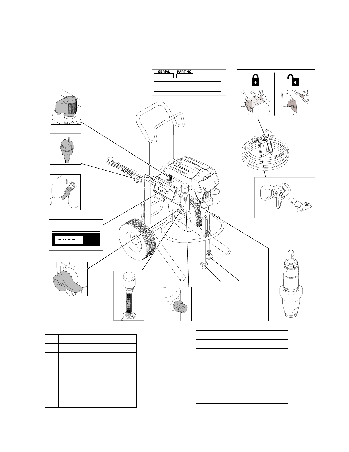
Component Identification
D
C
T
S
A
N
B
M
R
P
ps
E
A Pressure control
BPower Cord
C ON/OFF switch
D Digital Display
E Prime/Spray valve
FFilter
G Fluid outlet
H Siphon tube
K
F
HJ
G
J Drain tube
KPump
MHose
NSpray Gun
PSwitch Tip
R Tip Guard
S Trigger lock
T Serial Tag
332255A 5
Page 6
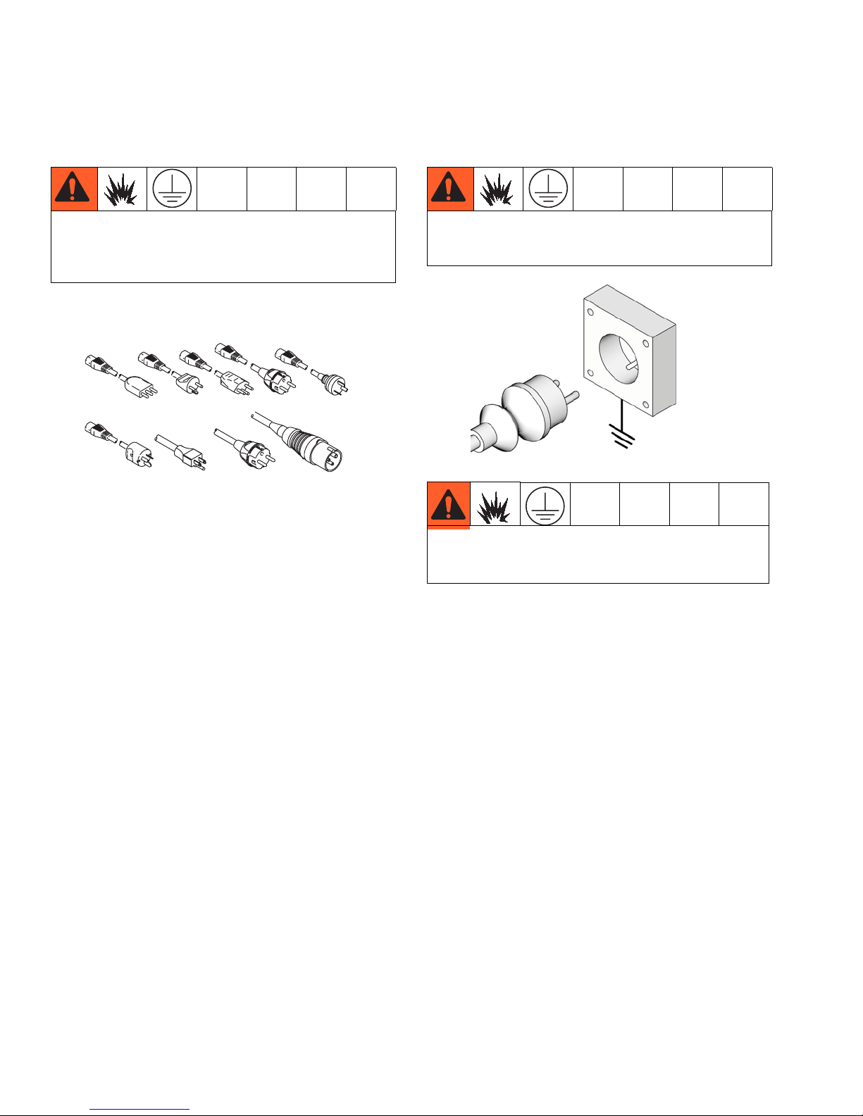
Grounding
Grounding
The equipment must be grounded to reduce the risk
of static sparking. Static sparking can cause fumes to
ignite or explode. Grounding provides an escape wire
for the electric current.
Sprayer Cord: The sprayer cord includes a grounding
wire with an appropriate grounding contact.
Air and fluid hoses: use only electrically conductive
hoses with a maximum of 500 ft. (150 m) combined hose
length to ensure grounding continuity. Check electrical
resistance of hoses. If total resistance to ground
exceeds 29 megohms, replace hose immediately.
Spray gun: ground through connection to a properly
grounded fluid hose and pump.
Fluid supply container: follow local code.
Object being sprayed: follow local code.
The plug must be plugged into an outlet that is properly installed and grounded in accordance with all
local codes and ordinances.
ti11730a
Do not modify plug! If it will not fit in outlet, have
grounded outlet installed by a qualified electrician.
Do not use an adapter.
Power Requirements
230V units require 220-240 VAC, 50/60 Hz, 8A, 1 phase.
6 332255A
Extension Cords
If an extension cord is necessary, use a 3-wire, 12 AWG
(2.5 mm
2
) minimum.
Page 7

Pails
Grounding
Solvent and oil/based fluids: follow local code. Use
only conductive metal pails, placed on a grounded surface. Do not place the pail on a nonconductive surface,
such as paper or cardboard, which interrupts grounding
continuity.
ti5850b
Grounding a metal pail: connect a ground wire to the
pail by clamping one end to pail and other end to a true
earth ground such as a water pipe.
To maintain grounding continuity when flushing or
relieving pressure: hold metal part of spray gun firmly
to side of a grounded metal pail. Then trigger gun.
ti5310c
ti5851a
332255A 7
Page 8

Pressure Relief Procedure
WASTE
Pressure Relief Procedure
Follow the Pressure Relief Procedure whenever
you see this symbol.
This equipment stays pressurized until pressure is
manually relieved. To help prevent serious injury from
pressurized fluid, such as skin injection, splashing
fluid and moving parts, follow the Pressure Relief Procedure when you stop spraying and before cleaning,
checking, or servicing the equipment.
1. Turn power OFF and unplug sprayer.
ti2707a
ti11730a
2. Turn pressure to lowest setting. Trigger gun to
relieve pressure. Turn prime valve down.
WASTE
3. If you suspect spray tip or hose is completely
clogged, or that pressure has not been fully relieved
after following these steps,
VERY SLOWLY
loosen
tip guard retaining nut or hose end coupling to
relieve pressure gradually, then loosen completely.
Now clear tip or hose obstruction.
ti2719a
8 332255A
Page 9

Setup
Setup
1. Connect Graco airless hose to sprayer.
Tighten securely.
ti21030a
2. Connect other end of hose to gun.
ti2702a
3. Tighten securely.
6. Fill throat packing nut with TSL to prevent
premature packing wear. Do this each time you
spray.
Approximate Fill Level
7. Turn power OFF.
ti2707a
8. Plug power supply cord into a properly grounded
electrical outlet.
ti2703a
4. Remove tip guard.
ti2769a
5. Check inlet strainer for clogs and debris.
ti2812a
9. Turn prime valve down.
ti2719a
10. Place siphon tube set in grounded metal pail partially filled with flushing fluid. Attach ground wire to
pail and to true earth ground. Do 1. - 5. of Startup,
page 10 to flush out storage oil shipped in sprayer.
Use water to flush water-base paint and mineral
spirits to flush oil-base paint and storage oil.
WASTE
ti2756B
FLUSH
332255A 9
Page 10

Startup
WASTE
599a
Startup
Do not operate or spray near children. Do not aim the
sprayer at, or spray any person or animal. Keep
hands and other body parts away from discharge. For
example, do not try to stop leaks with any part of the
body.
1. Turn pressure control to lowest pressure.
ti21028a
2. Turn power ON.
5. Hold gun against grounded metal flushing pail.
Trigger gun and increase fluid pressure to 1/2. Flush
1 minute.
WASTE
6. Inspect for leaks. Do not stop leaks with hand or a
rag! If leaks occur, do Pressure Relief. Tighten fittings. Do Startup, 1. - 5, page 10. If no leaks, proceed to 6.
7. Place siphon tube in paint pail.
ti2706a
3. Increase pressure to start motor and allow fluid
to circulate through drain tube for 15 seconds; then
turn pressure down.
ti21031a
4. Turn prime valve horizontal.Take spray gun trigger
safety OFF.
ti2712a
ti21028a
ti2714a
PAINT
8.
Trigger gun again into flushing pail until paint
appears. Move gun to paint pail and trigger for 20
seconds. Set gun safety ON. Assemble tip and
guard, page 11.
ti2713a
WASTE
10 332255A
Page 11

Tip and Guard Assembly
Tip and Guard Assembly
Do not operate or spray near children. Do not aim the
sprayer at, or spray any person or animal. Keep
hands and other body parts away from discharge. For
example, do not try to stop leaks with any part of the
body.
1. Insert metal seal and OneSeal.
ti2709a
2. Insert SwitchTip.
ti2708a
Spraying
1. Spray test pattern. Start with pressure turned to its
lowest setting, then gradually increase pressure
gradually until you achieve a consistent spray pattern without heavy edges. Use smaller tip size if
pressure adjustment can not eliminate heavy edges.
2. Hold gun perpendicular, 10-12 in. from surface.
Spray back and forth, overlapping by 50%. To prevent heavy spots, before pulling trigger, first move
gun using a back and forth motion. When you stop
spraying, after releasing trigger, continue to move
gun back and forth for a few seconds.
3. Screw assembly onto gun. Tighten.
ti2710a
332255A 11
Page 12

Clearing Clog
Clearing Clog
1. Release trigger, put safety ON.
4. Trigger gun to clear clog. Never point gun at your
hand or into a rag!
5. Put safety ON.
ti10166a
2. Rotate SwitchTip.
3. Take safety OFF.
ti10166a
6. Return Switch to original position.
7. Take safety OFF and continue spraying.
ti10167a
ti10167a
12 332255A
Page 13

Cleanup
WASTE
1. Turn power OFF and unplug sprayer.
Cleanup
6. Plug in sprayer. Turn power ON. Turn prime valve
horizontal.
ti2712a
ti2707a
ti11730a
2. Turn pressure to lowest setting. Trigger gun to
relieve pressure.
ti2599a
3. Put drain tube in pail. Turn prime valve down.
ti2719a
WASTE
RESÍDUOS
À JETER
DESECHO
ti2595a
ti11730a
ti2707a
7. Hold gun against paint pail. Take trigger safety OFF.
Trigger gun and increase pressure until flushing
fluid appears
ti2770a
PAI NT
8. Move gun to flushing pail, hold gun against pail, trigger gun to thoroughly flush system. Release trigger
and put trigger safety ON.
ti2599a
4. Remove guard and SwitchTip.
ti2769a
5. Remove siphon tube set from paint and place in
flushing fluid. Use water for water base paint and
mineral spirits for oil base paint.
WASTE
ti2756B
332255A 13
FLUSH
WASTE
9. Turn prime valve down and allow flushing fluid to
circulate for 1 to 2 minutes to clean drain tube.
ti2719a
Page 14

Cleanup
10. Raise siphon tube above flushing fluid and run
sprayer for 15 to 30 seconds to drain fluid. Turn
power OFF
PAIN T
ti2820a
FLUSH
ti2707a
11. Close drain valve. Trigger gun into flushing pail to
purge fluid from hose.
ti2712a
ti2713a
WASTE
12. Open prime valve.
ti2719a
14. If flushing with water, flush again with mineral spirits, or Pump Armor, to leave a protective coating to
prevent freezing or corrosion.
Pump Armor
ti2895a
15. Wipe sprayer, hose and gun with a rag soaked in
water or mineral spirits.
ti2776a
13. Remove filters from gun and sprayer, if installed.
Clean and inspect. Install filters.
ti2814a
14 332255A
Page 15

Digital Display
Digital Display
1. Follow Pressure Relief Procedure, page 8.
2. Plug sprayer in to grounded outlet. Turn power ON.
ti11730a
ti2706a
3. The pressure is displayed. Dashes indicate pressure is less than 200 psi (14 bar, 1.4MPa).
ti2786a
4. Press and hold display button to change pressure
units (psi, bar or MPa).
ti2888a
Stored Data
4. Press display button to display Data Point 2, motor
on time in hours.
5. Press display button to display Data Point 3, last
error code. Press and hold display button to erase
last error code.
ti2824a
6. Press display button to display Data Point 4,
software revision.
1. Turn power OFF.
ti2827a
2. While pressing display button, turn power ON to
enter Stored Data mode.
ti2706a
3. Model number is displayed and then Data Point 1,
power on time in hours, is displayed.
NOTE: FT600 = 595.
7. Press display button again to return to Data Point 1.
Turn power OFF to exit Stored Data.
ti2707a
332255A 15
Page 16

Digital Display
Main Menu Operation
Short press moves to next display. Press and hold
(5 seconds) changes units or resets data.
ti7484a
1. Follow Pressure Relief Procedure, page 8.
2. Turn power ON. Pressure display appears. Dashes
appear when pressure is less than 200 psi (14 bar,
1,4 MPa).
psi
Secondary Menu
1. Follow Pressure Relief Procedure, page 8.
2. Press DTS button and turn power switch ON.
3. Model (e.g. U595) displays for 1 sec, S/N for 1 sec,
then the serial number. Short press DTS button.
Total motor run hours displays. NOTE: FT600 = 595.
3. Short press DTS button to move to Job Gallons
(or Liters x 10). NOTE: JOB displays briefly, then
the number of gallons sprayed above 1000 psi
(70 bar, 7 MPa).
4. Press and hold to reset to zero, or short press DTS
button to move to Lifetime Gallons (or Liters x 10).
4. Short press DTS button. Last error code is
displayed; e.g., E=07 (see manual 332257).
5. Press and hold DTS button to clear error code to
zero. Short press to move to software REV.
Change Display Units
Press and hold DTS button for 8 seconds to change
pressure units (psi, bar, MPa) to desired units. Selection
of bar or MPa changes gallons to liters x 10.
psi
ti7487b
5. NOTE: LIFE displays briefly, then the number of gallons sprayed above 1000 psi (70 bar, 7 MPa)
16 332255A
Psi
bar
MPa
Page 17

Technical Data
Technical Data
FT600 (Model 278680)
US Metric
Maximum fluid working pressure 3300 psi 22.7 MPa, 227 bar
Maximum free-flow delivery 0.68 gpm 2.6 lpm
Recommended cycle rate for continuous duty 540 cycles per gallon 143 cycles per liter
Generator Minimum W 4000 4000
Motor Power 9/10 HP 671 W
Power Source 230V, 1 phase, 10A, 50/60 Hz 230V, 1 phase, 10A, 50/60 Hz
Dimensions
Weight 72 lb 33 kg
Length 21 in. 53.3 cm
Width 20.5 in. 52.1 cm
Height Handle Up: 39.5 in.
Handle Down: 29.5 in.
Basic Wetted Parts
Zinc-plated carbon steel, nylon,
stainless steel, PTFE, acetal,
chrome plating, leather,
UHMWPE, aluminum, tungsten
carbide
Noise Level
Sound Power 100 dBa* 100 dBA*
Sound Pressure 90 dBa* 90 dBA*
*Measured at 3 feet (1 meter) from equipment
Handle Up: 100.3 cm
Handle Down: 74.9 cm
Zinc-plated carbon steel, nylon,
stainless steel, PTFE, acetal,
chrome plating, leather,
UHMWPE, aluminum, tungsten
carbide
332255A 17
Page 18

Graco Standard Warranty
Graco warrants all equipment referenced in this document which is manufactured by Graco and bearing its name to be free from defects in
material and workmanship on the date of sale to the original purchaser for use. With the exception of any special, extended, or limited warranty
published by Graco, Graco will, for a period of twelve months from the date of sale, repair or replace any part of the equipment determined by
Graco to be defective. This warranty applies only when the equipment is installed, operated and maintained in accordance with Graco’s written
recommendations.
This warranty does not cover, and Graco shall not be liable for general wear and tear, or any malfunction, damage or wear caused by faulty
installation, misapplication, abrasion, corrosion, inadequate or improper maintenance, negligence, accident, tampering, or substitution of
non-Graco component parts. Nor shall Graco be liable for malfunction, damage or wear caused by the incompatibility of Graco equipment with
structures, accessories, equipment or materials not supplied by Graco, or the improper design, manufacture, installation, operation or
maintenance of structures, accessories, equipment or materials not supplied by Graco.
This warranty is conditioned upon the prepaid return of the equipment claimed to be defective to an authorized Graco distributor for verification of
the claimed defect. If the claimed defect is verified, Graco will repair or replace free of charge any defective parts. The equipment will be returned
to the original purchaser transportation prepaid. If inspection of the equipment does not disclose any defect in material or workmanship, repairs
will be made at a reasonable charge, which charges may include the costs of parts, labor, and transportation.
THIS WARRANTY IS EXCLUSIVE, AND IS IN LIEU OF ANY OTHER WARRANTIES, EXPRESS OR IMPLIED, INCLUDING BUT NOT LIMITED
TO WARRANTY OF MERCHANTABILITY OR WARRANTY OF FITNESS FOR A PARTICULAR PURPOSE
Graco’s sole obligation and buyer’s sole remedy for any breach of warranty shall be as set forth above. The buyer agrees that no other remedy
(including, but not limited to, incidental or consequential damages for lost profits, lost sales, injury to person or property, or any other incidental or
consequential loss) shall be available. Any action for breach of warranty must be brought within two (2) years of the date of sale.
GRACO MAKES NO WARRANTY, AND DISCLAIMS ALL IMPLIED WARRANTIES OF MERCHANTABILITY AND FITNESS FOR A
PARTICULAR PURPOSE, IN CONNECTION WITH ACCESSORIES, EQUIPMENT, MATERIALS OR COMPONENTS SOLD BUT NOT
MANUFACTURED BY GRACO
the warranty, if any, of their manufacturer. Graco will provide purchaser with reasonable assistance in making any claim for breach of these
warranties.
In no event will Graco be liable for indirect, incidental, special or consequential damages resulting from Graco supplying equipment hereunder, or
the furnishing, performance, or use of any products or other goods sold hereto, whether due to a breach of contract, breach of warranty, the
negligence of Graco, or otherwise.
FOR GRACO CANADA CUSTOMERS
The Parties acknowledge that they have required that the present document, as well as all documents, notices and legal proceedings entered into,
given or instituted pursuant hereto or relating directly or indirectly hereto, be drawn up in English. Les parties reconnaissent avoir convenu que la
rédaction du présente document sera en Anglais, ainsi que tous documents, avis et procédures judiciaires exécutés, donnés ou intentés, à la suite
de ou en rapport, directement ou indirectement, avec les procédures concernées.
. These items sold, but not manufactured by Graco (such as electric motors, switches, hose, etc.), are subject to
.
Graco Information
For the latest information about Graco products, visit www.graco.com.
TO PLACE AN ORDER, contact your Graco distributor or call 1-800-690-2894 to identify the nearest distributor.
All written and visual data contained in this document reflects the latest product information available at the time of publication.
Graco reserves the right to make changes at any time without notice.
For patent information, see www.graco.com/patents.
Original instructions.
International Offices: Belgium, China, Japan, Korea
GRACO INC. AND SUBSIDIARIES • P.O. BOX 1441 • MINNEAPOLIS MN 55440-1441 • USA
Copyright 2012, Graco Inc. All Graco manufacturing locations are registered to ISO 9001.
This manual contains English. MM 332255
Graco Headquarters: Minneapolis
www.graco.com
Revision A - February 2013
 Loading...