

Page 1
05217B
Instructions — Parts List
II 1/2 G T6
ITSO3ATEX11227
2575
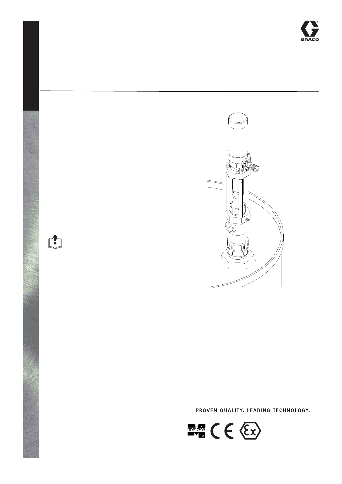
1:1 RATIO, 210 LITER (55 GAL.) SIZE
Foam-Cat
For use in drums of polyurethane chemicals.
180 psi (1.2 MPa, 12.4 bar) Maximum Air Working Pressure
180 psi (1.2 MPa, 12.4 bar) Maximum Material Working Pressure
* Mod
el No. 226946, Series B
Includes airtight bung adapter
Feed Pump Kit 217381
Includes two Model 226946 Feed Pumps, air dryer,
and air and fluid hoses.
Read warnings and instructions. See
page 2 for Table of Contents.
Feed Pump
®
307552K
EN
GRACO INC. P.O. BOX 1441 MINNEAPOLIS, MN 55440-1441
© Graco Inc., 1982. Graco Inc. is registered to I.S. EN ISO 9001
Page 2
Table of Contents
INSTRUCTIONS
Symbols . . . . . . . . . . . . . . . . . . . . . . . . . . . . . . . . . . . . 2
Installation . . . . . . . . . . . . . . . . . . . . . . . . . . . . . . . . . . 4
Operation . . . . . . . . . . . . . . . . . . . . . . . . . . . . . . . . . . . 7
Maintenance . . . . . . . . . . . . . . . . . . . . . . . . . . . . . . . . 8
Troubleshooting . . . . . . . . . . . . . . . . . . . . . . . . . . . . . 9
Service . . . . . . . . . . . . . . . . . . . . . . . . . . . . . . . . . . . . 10
Parts Drawing . . . . . . . . . . . . . . . . . . . . . . . . . . . . . . 12
Parts List . . . . . . . . . . . . . . . . . . . . . . . . . . . . . . . . . . 13
Technical Data . . . . . . . . . . . . . . . . . . . . . . . . . . . . . . 15
Graco Standard Warranty . . . . . . . . . . . . . . . . . . . . . . . 16
WARNING
Equipment misuse can cause the equipment to rupture or malfunction and result in serious injury.
This equipment is for professional use only.
•
Symbols
Warning Symbol
WARNING
This symbol alerts you to the possibility of serious
injury or death if you do not follow the instructions.
Caution Symbol
CAUTION
This symbol alerts you to the possibility of damage to
or destruction of equipment if you do not follow the
instructions.
• Read all instruction manuals, tags, and labels before operating the equipment.
• Use the equipment only for its intended purpose. If you are not sure, call your Graco distributor.
• Do not alter or modify this equipment.
• Check equipment daily. Repair or replace worn or damaged parts immediately.
• Do not exceed the maximum working pressure of the lowest rated component in your system. This equipment
has a 180 psi (1.2 MPa, 12.4 bar) maximum working pressure at 180 psi (1.2 MPa, 12.4 bar) maximum
incoming air pressure.
• Use fluids and solvents which are compatible with the equipment wetted parts. Refer to the Technical Data
section of all equipment manuals. Read the fluid and solvent manufacturer’s warnings.
• Do not use hoses to pull equipment.
• Route hoses away from traffic areas, sharp edges, moving parts, and hot surfaces. Do not expose Graco hoses
to temperatures above 82°C (180°F) or below –40°C (–40°F).
• Securely mount the pump. Do not attempt to operate it while holding it.
• Do not lift pressurized equipment.
• Comply with all applicable local, state, and national fire, electrical, and safety regulations.
2 307552
• Graco Inc. does not manufacture or supply any of the reactive chemical materials that may be used in this
equipment and is not responsible for their effects. Because of the vast number of chemicals that could be used
and their varying chemical reactions, before using this equipment, the buyer and the user should determine all
facts relating to the materials used, including any of the potential hazards involved. Particular inquiry and
investigation should be made into potential dangers relating to toxic fumes, fires, explosions, reaction times, and
exposure of human beings to the individual components or their resultant mixtures. Graco assumes no
responsibility for loss, damage, expense or claims for bodily injury or property damage, direct or consequential,
arising from the use of such chemical components.
Page 3
WARNING
TOXIC FLUID HAZARD
Hazardous fluid or toxic fumes can cause serious injury or death if splashed in the eyes or on the skin,
inhaled, or swallowed.
•
Know the specific hazards of the fluid you are using.
• Store hazardous fluid in an approved container. Dispose of hazardous fluid according to all local, state and
national guidelines.
• Any additives to the air supply, such as oil or anti–freeze will be exhausted into the atmosphere.
• Always wear protective eyewear, gloves, clothing and respirator as recommended by the fluid and solvent
manufacturer.
FIRE AND EXPLOSION HAZARD
Improper grounding, poor ventilation, open flames or sparks can cause a hazardous condition and result
in a fire or explosion and serious injury.
•
Ground the equipment. Refer to Grounding on page 5.
• If there is any static sparking or you feel an electric shock while using this equipment, stop pumping
immediately. Do not use the equipment until you identify and correct the problem.
• Provide fresh air ventilation to avoid the buildup of flammable fumes from solvents or the fluid being sprayed.
• Keep the work area free of debris, including solvent, rags, and gasoline.
• Electrically disconnect all equipment in the work area.
• Extinguish all open flames or pilot lights in the work area.
• Do not smoke in the work area.
• Do not turn on or off any light switch in the work area while operating or if fumes are present.
• Do not operate a gasoline engine in the work area.
MOVING PARTS HAZARD
Moving parts can pinch or amputate your fingers.
•
Keep clear of all moving parts when starting or operating the pump.
• Before servicing the equipment, follow the Pressure Relief Procedure on page 7 to prevent the equipment
from starting accidentally.
307552 3
Page 4
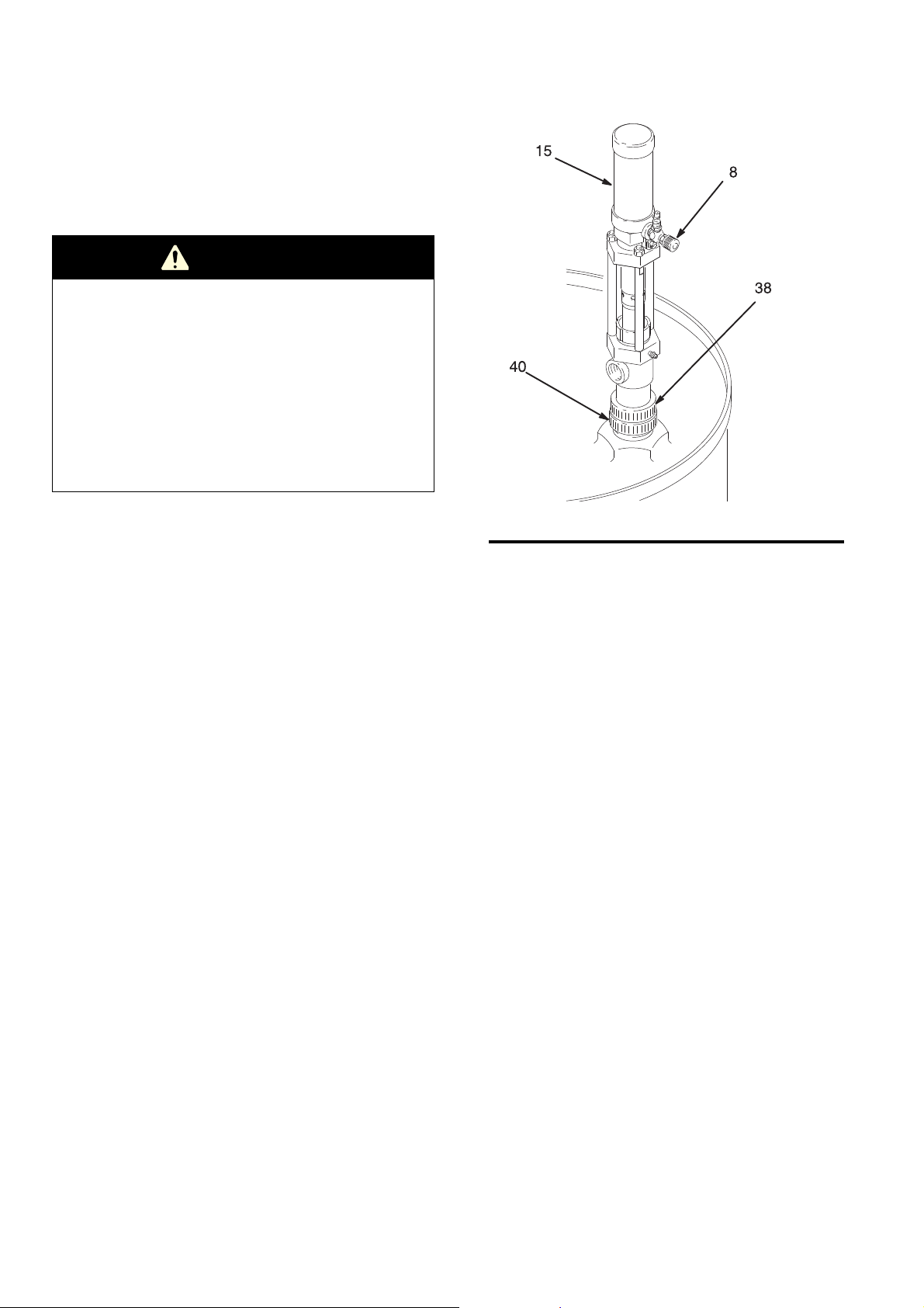
Installation
05217B
FIG.1
NOTE: The terms ISO and RES used in the text refer to
the polyurethane foam chemicals, Isocyanate and Resin.
NOTE: Reference numbers and letters in parentheses in
the text refer to the figure illustrations and the Parts
Drawing.
WARNING
A bleed–type master air valve (E) is required in your
system, to help reduce the risk of serious injury,
including splashing fluid in the eyes or on the skin, and
injury from moving parts if you are adjusting or repairing
the pump.
The bleed–type master air valve (E) relieves air trapped
between this valve and the pump after the pump is shut
off. Trapped air can cause the pump to cycle
unexpectedly and result in serious injury, including
amputation. Locate the valve close to the pump.
Installing the Feed Pumps
1. Screw the bung adapter (40) and pump tightly into the drum cover. See Fig 1.
2. Tighten the retainer (38) firmly to complete the airtight seal.
3. Separate the two halves of the identification label (15) along the perforation. Clean the surface of the air motor with solvent and apply the appropriate label (RES or ISO) to identify the type of material being pumped.
4. Install an air regulator in the feed pump air inlet to control pump speed. To install, remove the air valve (8) and use suitable adapters for the regulator and pin fitting. Use thread sealer on male threads.
4 307552
Page 5
Installation
TI1052
FIG.2
5. Connect an air supply hose to the 1/4 npt air line
coupler (13). Air supply hoses (103) are supplied in
Kit 217381. See Fig 3, page 6.
6. Connect a fluid supply hose from the 3/4 npt(f) fluid
outlet of the ISO feed pump to the inlet fitting of the
ISO proportioning pump, using adapters as needed.
Then connect a fluid supply hose between the RES
feed pump and RES proportioning pump.
CAUTION
Be sure all hose connections in your polyurethane
foam spray system are clearly labeled ISO or RES
and make connections only with identically labeled
components to avoid material crossing.
Crossing polyurethane materials will cause the
material to harden in the equipment and may
permanently damage it.
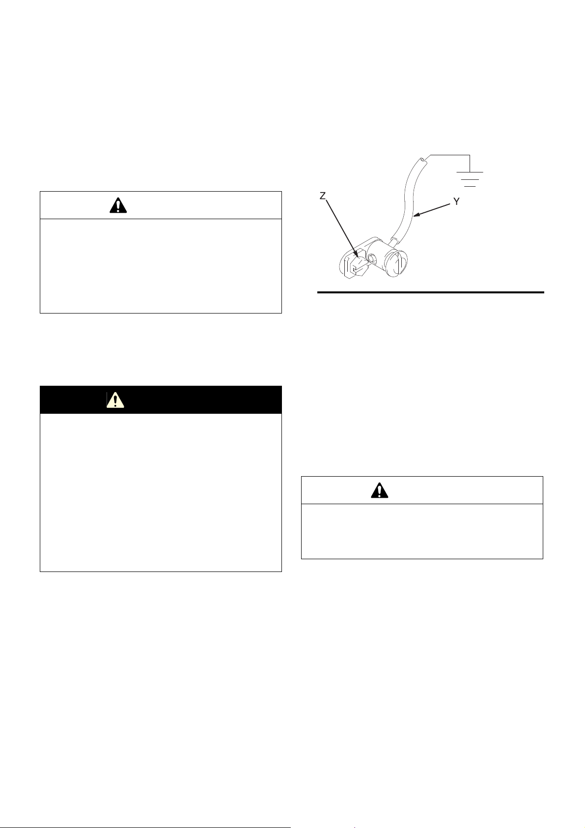
Grounding
Remove the ground screw (Z) and insert through eye of
ring terminal at the end of ground wire (Y). Fasten ground
screw back onto pump and tighten securely. See Fig 2.
Connect the other end of the wire to a true earth ground.
Order Part No. 222011 Ground Wire and Clamp.
Feed Pump Kit Installation
The following instructions assume you are using this kit
with a Graco Foam–Cat Sprayer.
WARNING
Static electricity is created by the high velocity flow of
fluid through the pump and hoses. If every part of the
spray system, and all objects in the spray area are not
properly grounded, the static electricity may cause
sparking. Sparks can ignite fumes from solvents and the
fluid being sprayed, dust particles, and other flammable
substances, causing a fire, explosion and serious bodily
injury and property damage.
To reduce the risk of static sparking, use only conductive
air and fluid hoses and be sure your entire system is
properly grounded. Ground the feed pumps as
explained below.
1. Install the feed pumps as described in Steps 1–4, on
page 4.
2. Mount the Air Dryer (105) in any suitable location.
Refer to manual 307548 for the mounting hole
diagram. See Fig 3.
3. Unscrew the air dryer ring (F) to remove the bowl.
See Fig 3. Remove the filter and fill the bowl with the
desiccant, provided. Reassemble.
CAUTION
One end of each fluid hose and each drum nipple (G)
of the drum fittings (H) is labeled ISO or RES. Make
only ISO to ISO and RES to RES connections to avoid
material crossing.
4. Install the drum fittings (H) in the 3/4 in. vent port of
the proper drum.
307552 5
Page 6

Installation
M
FIG.3
KEY
A Air Line
B Air Line Filter
E Bleed-type master valve
F Air Dryer Ring
G Nipple
H Drum Air Fittings
J Pin Fitting
K Ball Valve
L Bushing
M Air Hose (Air Dryer)
N Special Air Coupler
7 Pin Fitting
8 Air Control Valve
13 Air Line Coupler
103 Air Hoses (Pump)
104 Bushing
105 Air Dryer
5. Connect the dry air hoses (M) to the identically labeled drum fittings using the special pin fitting (J) and coupler (N). See Fig 3.
The special air line fitting (J) and coupler (N) are
designed to prevent accidentally coupling an
unregulated air supply hose to the container.
Unregulated air can overpressurize the container and
cause it to rupture, resulting in serious bodily injury
and property damage. If the coupler and fitting ever
needs to be replaced use only original Graco parts.
Never substitute a different type of coupler and fitting!
WARNING
05218
6. Attach a bushing (104) to one end of two of the air supply hoses (103) and attach a bushing to each end of the third air hose. See the Parts Drawing on page 13.
7. Connect one air hose between the feed pump and
the 1/2 npt(f) air manifold on the side of the FoamCat sprayer pump stand. Repeat for the other feed
pump.
8. Connect the hose with the two bushings between the 1/2 npt(f) air inlet of the Air Dryer and a bleed– type master air valve (E), required. Then connect the main air supply line to the air valve.
9. Connect the ISO fluid hose between the 3/4 npt(f) fluid outlet of the ISO feed pump and the 3/4 npt(f) inlet of the corresponding displacement pump. Repeat for the RES pumps.
6 307552
Page 7

Operation
Pressure Relief Procedure
WARNING
PRESSURIZED EQUIPMENT HAZARD
The system pressure must be manually relieved to
prevent the system from starting or spraying
accidentally. To reduce the risk of an injury from
accidental spray from the gun, splashing fluid, or moving
parts, follow the Pressure Relief Procedure whenever
you:
• are instructed to relieve the pressure,
• have an air supply interruption,
• stop spraying,
• check or service any of the system equipment,
• or install or clean the spray nozzle.
Starting and Operating the Pump
This pump is designed to be used with a Graco Foam-Cat
Sprayer. If you have purchased such a sprayer, complete
warning and operating instructions are contained in the
manual (307541 or 307542) which accompanied the
sprayer. If you have misplaced these manuals, obtain
additional copies by contacting your Graco distributor.
Changing Drums
CAUTION
To avoid crossing material when changing drums,
complete the changing of one type of material before
starting the other.
1. Disconnect the hose coupler (N) from the Air Dryer drum fittings (H). See Fig 3.
2. Leave the ball valve (K) open for a few minutes to release the air pressure in the drum, then close the valves.
3. Remove the pump and the drum fittings from the drum cover and install them in the new drum of material.
4. Repeat this procedure for the other material.
In general operation, when the pump is used for transfer
and supply operations with no dispensing valve, the pump
will run whenever air is supplied.
Normally, the Feed Pump air valve is opened before any
other equipment in the spray system is turned on. This is
so fluid can be supplied to the components immediately.
For shutdown, disconnect the air line coupler (13). See Fig
4.
Never let the pump run when the drum is empty. A dry
pump can quickly accelerate to a high speed and damage
itself. If the pump is running too fast, stop it immediately
and check and refill the material supply, or flush the pump
with a compatible solvent if you stop spraying for the day.
Always prime the entire system with fluid to remove any air
pumped into the system. Refer to Manual 307541 or
307542. Don’t let the material harden in the pump.
Feed Pump Kit
Refer to the operation instructions on page 2 of manual
307548, which was supplied with the Air Dryer, and the
above instructions for operating the Feed Pumps.
307552 7
Page 8

Maintenance
05219B
13
7
8
36
34
28
03765
FIG.5
Bung Adapter
If the ISO material shows signs of crystallization, and
whenever the pump is removed from the drum, check the oring (39) and gasket (41) for wear or damage, replacing as
needed. Refer to the Parts Drawing.
ISO Pump Packing Protection and Lubrication
CAUTION
Use only IPL (Isocyanate Pump Lube) to lubricate the
packings of the feed pump. Other types of lubricant
are not as effective in preventing packing damage.
1. Insert the 14.6 oz. cartridge (16) of IPL in a standard grease gun.
2. At shutdown each day, stop the pump with the rod (34) in the down position, then lubricate the packings liberally with IPL through the grease fitting (36). Proper lubrication prevents pump sticking. See Fig 4.
3. Wipe off the extra, contaminated IPL from around the top of the packing nut (28) and displacement rod (34).
4. Coat the displacement rod with fresh IPL.
Air Lubrication
If the air supply is dry, periodically oil the air motor. For
manual lubrication, turn off the air, put about 15 drops of
lightweight motor oil in the air inlet (7), reconnect the
hose, and turn on the air. See Fig 4.
1. Open the air valve (8) or regulator to start the pump. Allow the pump to cycle slowly for at least 5 minutes.
Flushing
CAUTION
Be sure the solvent used is compatible with the
material to be pumped to avoid material
contamination.
1. Connect a short hose to the pump outlet.
2. Insert the pump intake into a pail of solvent.
3. Direct the fluid hose into the pail.
2. Stop and disconnect the air hose.
3. Be sure to relieve the fluid pressure.
4. Push up on the intake valve (35) check plate to drain the lower part of the pump. See Fig 5.
5. Turn the pump over to drain the upper part of the pump.
Adjusting the Packing Nut
WARNING
Follow the Pressure Relief Procedure on page 7
before adjusting the packing nut.
Periodically, check the tightness of the packing nut (28).
It should be tight enough to prevent leakage; no tighter.
See Fig. 4. If the leakage cannot be stopped, change
the packings to prevent exposure to the fluid being
pumped.
8 307552
Page 9

Troubleshooting
Check all possible remedies before disassembling the
WARNING
Follow the Pressure Relief Procedure on page 7
before servicing the pump.
PROBLEM CAUSE SOLUTION
Pump fails to operate Material crystallized Clean pump, use IPL more liberally
Dirty or worn air motor parts Clean air motor, repair
pump.
Inadequate air supply or restricted
line
Insufficient air pressure, closed or
clogged air valves
Clogged material hose or valve Clear obstruction
Worn or damaged valves or seals Service pump
Pump operates, but output is low on
both strokes
Pump operates, but output is low on
down stroke
Pump operates, but output is low on
up stroke
Erratic or accelerated operation Exhausted material supply Refill
Clogged material hose or valve Clear obstruction
Exhausted material supply Refill
Worn or damaged valves or seals Service pump
Worn or damaged valves or seals Service pump
Intake valve held open Clear valve, service pump
Worn or damaged valves or seals Service pump
Piston valve held open Clear valve, service pump
Broken air motor compression spring Replace spring
Clear line; see TECHNICAL DATA
Check valves; increase pressure
NOTE: Removing the muffler (P, Fig 6) will increase both the pump flow rate and the exhaust noise and will reduce icing.
307552 9
Page 10

Service
03766B
FIG.6
TORQUE TO
11 N•m (8 ft–lb)
Disconnecting the Air Motor
Flush the pump, disconnect the air supply and relieve all
pressures in the system. Remove the pump from its
mounting. Unscrew the tie rod locknuts (3), remove the
screw (5) and barrel (4) set and lift the air motor.
Unscrew the rod (34). See Fig 6.
Reconnecting the Air Motor
Use lithium base grease on the threads of the rod (34).
Insert the muffler (P) as shown. Hand tighten the rod (34)
into the air motor connecting rod. Install the screw and
barrel set (4 and 5). Lubricate the tie rod threads. To
ensure alignment, thread the tie rod locknuts (3) loosely
onto the tie rods, then torque evenly to 11 N•m (8 ft–lb).
See Fig 6.
Intake Valve
Unscrew the intake valve housing (35). Disassemble,
clean and inspect all parts. Replace worn or damaged
parts. See Fig 7.
Piston Valve
Use a strap wrench to grip the cylinder (25) near the
housing (24) and unscrew it from the outlet housing. Pull
the cylinder down, then loosen the lower nut (19).
Unscrew the piston housing (33). Clean and inspect all
parts. Replace worn or damaged parts. Screw the
connecting rod all the way into the piston housing (33).
Tighten the upper nut (19) against the piston housing and
adjust the lower nut (19) to allow the piston disk (29) free
travel of 3.1 mm (0.1235 in.). See Fig 7.
Throat Packings
Remove the cylinder (25). Loosen the packing nut (28).
Pull the displacement rod (34) down and out. Remove
the glands (21,22) and packings (32). Clean and inspect
all parts. Replace worn or damage parts.
Reassemble the pump. Install packings one at a time to
be sure they nest properly. Leave the packing nut (28)
loosen until the displacement rod (34) has been
installed. Then tighten the packing nut firmly to seat the
packings.
NOTE: Insert the displacement rod from the top of the
outlet housing (24) to prevent packing damage.
Back the packing nut off until it no longer contacts the
packings, then turn it in just until contact is made.
10 307552
Page 11

Service
28
21
*32
*22
24
18
38
39
40
41
25
30
34
19
26
19
33
29
23
31*
27
18
35
36
05221
FIG.7
Torque to 31 N•m (23 ft–lb)
Torque to 33 N•m (24 ft–lb)
Lips face down
307552 11
Page 12

Parts Drawing
10
11
9
12
14
13
7
8
4
3
15
17
28
21
*32
*22
24
18
38
39
40
41
25
30
34
19
26
19
33
29
23
31*
27
18
35
36
37
03768
05221
03768C
5
12 307552
Page 13

Parts List
05222
102
Model 226946, Series B Includes Items 1–42
Ref.
Part
No.
No.
1 100508
3 104541 LOCKNUT, M8 w/nylon insert 3
4 15B249 PIN, barrel 1
5 15B250 SCREW 1
6 177171 TIE ROD 3
7 169969 FITTING, air line 1
8 206264 NEEDLE VALVE ASSEMBLY
9 157628
10 165722 BODY 1
11 166531 RING, friction washer 1
12 206263 NEEDLE 1
13 114558 COUPLER, air line 1
14 215963 AIR MOTOR see manual 307456 1
15 178600 LABEL, ISO/RES 3
16 106565 ISO PUMP LIQUID, 14.6 oz 1
17 217383 DISPLACEMENT PUMP
18 104537
19 105775 NUT, hex, M14 x 1.5
21* 178543 GLAND, female packing, PTFE 1
22* 172385 GLAND, male packing, sst 1
23 172393 WASHER, SST 1
24 178542 HOUSING, outlet 1
25 172416 CYLINDER 1
26 177150 ROD, connecting 1
27 177151 PISTON, pump 1
28 177152 NUT, packing 1
29 177155 DISK, piston 1
30 177156
31* 172489 CUP, piston 1
32* 172487 V-PACKING 3
33 177168 HOUSING, valve piston 1
34 217189 ROD, displacement 1
35 217102 VALVE, intake 1
36 101281 FITTING, grease 1
37 217359 BUNG ADAPTER
38 178576
39 106536 PACKING, o–ring, ethylene propylene 1
Description Qty.
DRIVESCREW, #4 x 3/16”, type U
Includes items 9–12
PACKING, o-ring, nitrile rubber
Includes Items 18–36
O–RING, PTFE
O–RING, Viton
Includes Items 38–41
RETAINER, O–RING
®
Feed Pump Kit 217381 Includes Items 101–105
Ref.
Part No. Description Qty.
No.
101 226946 1:1 RATIO FAST-FLO FEED PUMP
2
See parts at left. 2
102 217382 HOSE, fluid, cpld 3/4 npt(f), 10ft (3m) 2
103 200991 HOSE, fluid, cpld 1/4 npt(fbe), 10ft (3m) 3
104 100206 BUSHING, 1/2 x 1/4 npt 4
105 217341 AIR DRYER; see 307548 for parts 1
1
1
1
2
1
1
1
40 178575 ADAPETER, bung, 2” npsm(m) 1
41 106537 GASKET, polyethylene 1
* These parts are included in Repair Kit 213013, which
may be purchased separately.
Keep these spare parts on hand to reduce down time.
307552 13
Page 14

Notes
___________________________________________________________________________________________
___________________________________________________________________________________________
___________________________________________________________________________________________
___________________________________________________________________________________________
___________________________________________________________________________________________
___________________________________________________________________________________________
___________________________________________________________________________________________
___________________________________________________________________________________________
___________________________________________________________________________________________
___________________________________________________________________________________________
___________________________________________________________________________________________
___________________________________________________________________________________________
___________________________________________________________________________________________
___________________________________________________________________________________________
___________________________________________________________________________________________
___________________________________________________________________________________________
___________________________________________________________________________________________
___________________________________________________________________________________________
___________________________________________________________________________________________
___________________________________________________________________________________________
___________________________________________________________________________________________
___________________________________________________________________________________________
___________________________________________________________________________________________
___________________________________________________________________________________________
___________________________________________________________________________________________
14 307552
Page 15

Technical Data
1.3 m
(51.7”)
905 mm
(35.6”)
OUTLET
3/4 npt(f)
Recommended Air Operating Range . . . . . . . . . . . . . . . 40–180 psi (0.3–1.2 MPa, 3–12 bar)
Air Consumption . . . . . . . . . . . . . . . . . . Approx. 0.05 m
. . . . . . . . . . . . . . . . . . . . . . . . . . . . . . . . . . . . . . Up to 0.2 m
Max. Recommended Pump Speed (Continuous Duty) . . . . . . . . . . .. . . . . . . 100 cycles/min
Fluid Outlet . . . . . . . . . . . . . . . . . . . . . . . . . . . . . . . . . . . . . . . . . . . . . . . . . . . . . . . . 3/4 npt(f)
Air Inlet . . . . . . . . . . . . . . . . . . . . . . . . . . . . . . . . . . . . . . . . . . . . . . . . . . . . . . . . . . . 1/4 npt(f)
Fluid Inlet . . . . . . . . . . . . . . . . . . . . . . . . . . . . . . . . . . . . . . . . . . . . . . . . . . . .. . . . 1–1/2 npt(f)
Wetted Parts . . . . . . . . . . . . . . . . . . . . . . Carbon steel, 300 series stainless steel, Leather,
Cadmium plated ductile iron, Chrome and zinc plated steel, PTFE
Weight . . . . . . . . . . . . . . . . . . . . . . . . . . . . . . . . . . . . . . . . . . . . . . . . .. . . . . . 6.5 kg (14.25 lb)
Max. Operating Temperature . . . . . . . . . . . . . . . . . . . . . . . . . . . . . . . . . . . . . . 49°C (120°F)
Sound Data
Sound Pressure Level at 100 psi (0.7 MPa, 7 bar) . . . . . . . . . . . . . . . . . . 72 dB(A)
Sound Power Level at 100 psi (0.7 MPa, 7 bar) . . . . . . . . . . . . . . . . . . . . 82 dB(A)
Sound Pressure Level at 65 psi (0.4 MPa, 4.5 bar) . . . . . . . . . . . . . . . . . . 70 dB(A)
Sound Power Level at 65 psi (0.4 MPa, 4.5 bar) . . . . . . . . . . . . . . . . . . . . 70 dB(A)
3
/min at 4 liters/min and 5.5 bar input
(1.8 cfm at 1 gpm and 80 psi)
(6.8 cfm at 5 gpm and 100 psi)
3
/min at 20 liters/min and 6.9 bar
20 liters/min (5 gpm
Polyethylene, Tefzel
)
307552 15
Page 16

Graco Standard Warranty
Graco warrants all equipment manufactured by Graco and bearing its name to be free from defects in material and workmanship on the date of
sale by an authorized Graco distributor to the original purchaser for use. With the exception of any special, extended, or limited warranty published
by Graco, Graco will, for a period of twelve months from the date of sale, repair or replace any part of the equipment determined by Graco to be
defective. This warranty applies only when the equipment is installed, operated and maintained in accordance with Graco’s written
recommendations.
This warranty does not cover, and Graco shall not be liable for general wear and tear, or any malfunction, damage or wear caused by faulty
installation, misapplication, abrasion, corrosion, inadequate or improper maintenance, negligence, accident, tampering, or substitution of non–
Graco component parts. Nor shall Graco be liable for malfunction, damage or wear caused by the incompatibility of Graco equipment with
structures, accessories, equipment or materials not supplied by Graco, or the improper design, manufacture, installation, operation or
maintenance of structures, accessories, equipment or materials not supplied by Graco.
This warranty is conditioned upon the prepaid return of the equipment claimed to be defective to an authorized Graco distributor for verification of
the claimed defect. If the claimed defect is verified, Graco will repair or replace free of charge any defective parts. The equipment will be returned
to the original purchaser transportation prepaid. If inspection of the equipment does not disclose any defect in material or workmanship, repairs will
be made at a reasonable charge, which charges may include the costs of parts, labor, and transportation.
THIS WARRANTY IS EXCLUSIVE, AND IS IN LIEU OF ANY OTHER WARRANTIES, EXPRESS OR IMPLIED, INCLUDING BUT NOT LIMITED
TO WARRANTY OF MERCHANTABILITY OR WARRANTY OF FITNESS FOR A PARTICULAR PURPOSE.
Graco’s sole obligation and buyer’s sole remedy for any breach of warranty shall be as set forth above. The buyer agrees that no other remedy
(including, but not limited to, incidental or consequential damages for lost profits, lost sales, injury to person or property, or any other incidental or
consequential loss) shall be available. Any action for breach of warranty must be brought within two (2) years of the date of sale.
Graco makes no warranty, and disclaims all implied warranties of merchantability and fitness for a particular purpose in connection with
accessories, equipment, materials or components sold but not manufactured by Graco. These items sold, but not manufactured by Graco (such as
electric motors, switches, hose, etc.), are subject to the warranty, if any, of their manufacturer. Graco will provide purchaser with reasonable
assistance in making any claim for breach of these warranties.
In no event will Graco be liable for indirect, incidental, special or consequential damages resulting from Graco supplying equipment hereunder, or
the furnishing, performance, or use of any products or other goods sold hereto, whether due to a breach of contract, breach of warranty, the
negligence of Graco, or otherwise.
FOR GRACO CANADA CUSTOMERS
The parties acknowledge that they have required that the present document, as well as all documents, notices and legal proceedings entered into,
given or instituted pursuant hereto or relating directly or indirectly hereto, be drawn up in English. Les parties reconnaissent avoir convenu que la
rédaction du présente document sera en Anglais, ainsi que tous documents, avis et procédures judiciaires exécutés, donnés ou intentés à la suite
de ou en rapport, directement ou indirectement, avec les procedures concernées.
Graco Information
TO PLACE AN ORDER, contact your Graco distributor, or call one of the following numbers:
1–800–328–0211 (Toll Free)
612–623–6921
612–378–3505 (Fax)
All written and visual data contained in this document reflects the latest product information available at the time of publication.
16 307552
Graco reserves the right to make changes at any time without notice.
Sales Offices: Minneapolis, Detroit
International Offices: Belgium, Korea, Hong Kong, Japan
www.graco.com
PRINTED IN THE USA 307552 05/1982, Revised 07/2019
 Loading...