

Page 1
Instructions – Parts List
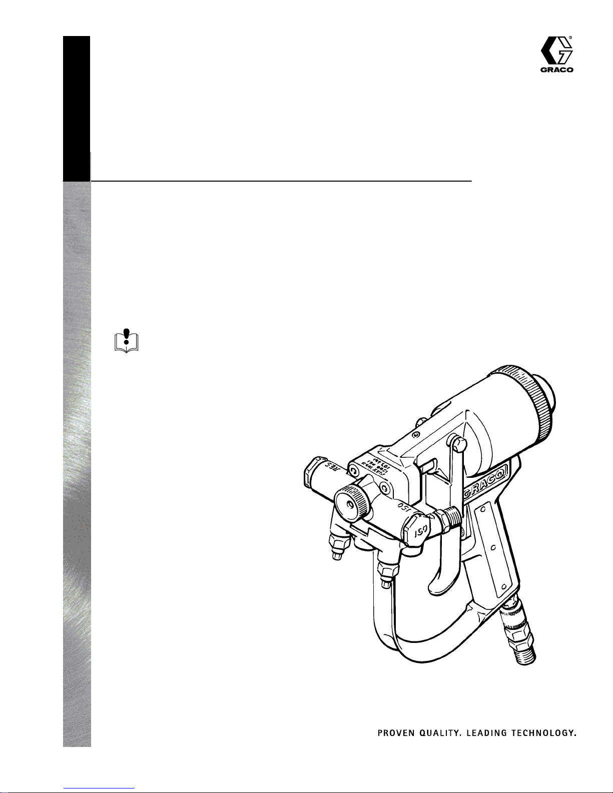
Foam-Catr Foam Gun
1500 psi (10.5 MPa, 105 bar) Maximum Working Pressure
Model 217373, Series E
Order a needle/nozzle kit separately. See page 5.
U.S. Patent No. 4,427,153
U.K. Patent No. 0,116,613
Patented Bréveté 1986 Canada
Other Foreign Patents Pending.
Read warnings and instructions.
See page 2 for Table of Contents.
307546T
GRACO INC.ąP.O. BOX 1441ąMINNEAPOLIS, MNą55440-1441
Copyright 1982, Graco Inc. is registered to I.S. EN ISO 9001
Page 2

Table of Contents
Symbols 3. . . . . . . . . . . . . . . . . . . . . . . . . . . . . . . . . . . . . .
Warnings 3. . . . . . . . . . . . . . . . . . . . . . . . . . . . . . . . . . . . . .
Spray Nozzle Performance Chart 5. . . . . . . . . . . . . . . . .
Pour Nozzle Performance Chart 5. . . . . . . . . . . . . . . . . .
Installation 6. . . . . . . . . . . . . . . . . . . . . . . . . . . . . . . . . . . . .
Safety 7. . . . . . . . . . . . . . . . . . . . . . . . . . . . . . . . . . . . . .
Grounding 7. . . . . . . . . . . . . . . . . . . . . . . . . . . . . . . . . . .
Optional O-rings 7. . . . . . . . . . . . . . . . . . . . . . . . . . . . .
Installing a Needle/Nozzle Kit on a New Gun 8. . . . .
Connecting Hoses 10. . . . . . . . . . . . . . . . . . . . . . . . . . .
Operation 11. . . . . . . . . . . . . . . . . . . . . . . . . . . . . . . . . . . .
Pressure Relief Procedure 11. . . . . . . . . . . . . . . . . . . .
Adjusting Cleanoff Air 12. . . . . . . . . . . . . . . . . . . . . . . .
Spray Pattern Adjustment 13. . . . . . . . . . . . . . . . . . . . . .
Effects of Fluid Temperature and Pressure 13. . . . . .
Observing the Effects of Varying Fluid Temperature
and Pressure 13. . . . . . . . . . . . . . . . . . . . . . . . . . . . .
About Surface Texture 13. . . . . . . . . . . . . . . . . . . . . . .
About Poured Foam Texture 13. . . . . . . . . . . . . . . . . .
Surface Texture Descriptions 14. . . . . . . . . . . . . . . . . . . .
Replacing the Needle/Nozzle Assembly 15. . . . . . . . . .
Cleaning the Nozzle 17. . . . . . . . . . . . . . . . . . . . . . . . . . .
Foam Spraying Nozzles 17. . . . . . . . . . . . . . . . . . . . . .
Foam Pouring Nozzles 17. . . . . . . . . . . . . . . . . . . . . . .
Maintenance 18. . . . . . . . . . . . . . . . . . . . . . . . . . . . . . . . . .
Keeping the Gun Clean While Spraying 18. . . . . . . .
Fluid Buildup on Nozzle 18. . . . . . . . . . . . . . . . . . . . . .
Fluid Buildup on Needle 18. . . . . . . . . . . . . . . . . . . . . .
Cleaning the Fluid Manifold 18. . . . . . . . . . . . . . . . . . .
Shutdown 18. . . . . . . . . . . . . . . . . . . . . . . . . . . . . . . . . .
Flushing 19. . . . . . . . . . . . . . . . . . . . . . . . . . . . . . . . . . . . . .
Troubleshooting 20. . . . . . . . . . . . . . . . . . . . . . . . . . . . . . .
Service 22. . . . . . . . . . . . . . . . . . . . . . . . . . . . . . . . . . . . . .
Needle Valves 22. . . . . . . . . . . . . . . . . . . . . . . . . . . . . .
Piston 23. . . . . . . . . . . . . . . . . . . . . . . . . . . . . . . . . . . . .
Check Valve 23. . . . . . . . . . . . . . . . . . . . . . . . . . . . . . . .
Air Valve 24. . . . . . . . . . . . . . . . . . . . . . . . . . . . . . . . . . .
Parts 26. . . . . . . . . . . . . . . . . . . . . . . . . . . . . . . . . . . . . . . .
Accessories 28. . . . . . . . . . . . . . . . . . . . . . . . . . . . . . . . . .
Technical Data 29. . . . . . . . . . . . . . . . . . . . . . . . . . . . . . . .
Nozzle Kit Summary 29. . . . . . . . . . . . . . . . . . . . . . . . . . .
Graco Standard Warranty 30. . . . . . . . . . . . . . . . . . . . . .
Graco Information 30. . . . . . . . . . . . . . . . . . . . . . . . . . . . .
2 307546
Page 3
Symbols
Warning Symbol
WARNING
This symbol alerts you to the possibility of serious
injury or death if you do not follow the instructions.
WARNING
FIRE AND EXPLOSION HAZARD
Improper grounding, poor air ventilation, open flames, or sparks can cause a hazardous condition and
result in a fire or explosion and serious injury.
D Ground the equipment and the object. See Grounding on page 7.
D Provide fresh air ventilation to avoid the buildup of flammable fumes from solvent or the fluid being
dispensed.
D Extinguish all the open flames or pilot lights in the dispense area.
D Keep the dispense area free of debris, including solvent, rags, and gasoline.
D Do not turn on or off any light switch in the dispense area while operating or if fumes are present.
Caution Symbol
CAUTION
This symbol alerts you to the possibility of damage to
or destruction of equipment if you do not follow the
instructions.
D Do not smoke in the dispense area.
D Do not operate a gasoline engine in the dispense area.
D If there is any static sparking while using the equipment, stop dispensing immediately. Identify
and correct the problem.
INJECTION HAZARD
Spray from the gun, hose leaks, or ruptured components can inject fluid into your body and cause
extremely serious injury, including the need for amputation. Splashing fluid in the eyes or on the skin
can also cause serious injury.
D Fluid injected into the skin might look like just a cut, but it is a serious injury. Get immediate medi-
cal attention.
D Do not point the gun at anyone or at any part of the body.
D Do not put hand or fingers over the gun nozzle.
D Do not stop or deflect fluid leaks with your hand, body, glove, or rag.
D Be sure the gun trigger safety operates before dispensing.
D Lock the gun trigger safety when you stop dispensing.
D If the nozzle clogs, stop dispensing, lock the gun trigger safety, and follow the instructions of page
17 to clean the nozzle.
D Keep the tip of the nozzle and the nozzle head free of foam buildup. Foam buildup on the nozzle
can cause foam shots to be misdirected and splash foam in the eyes or on the skin.
D Follow the Pressure Relief Procedure on page 11 whenever you: are instructed to relieve pres-
sure; stop dispensing; clean, check, or service the equipment; and install or clean the nozzle.
D Tighten all the fluid connections before operating the equipment.
D Check the hoses, tubes, and couplings daily. Replace worn, damaged, or loose parts immediately.
Permanently coupled hoses cannot be repaired; replace the entire hose.
307546 3
Page 4
INSTRUCTIONS
WARNING
EQUIPMENT MISUSE HAZARD
Equipment misuse can cause the equipment to rupture, malfunction, or start unexpectedly and result
in a serious injury.
D This equipment is for professional use only.
D Read all the instruction manuals, tags, and labels before operating the equipment.
D Use the equipment only for its intended purpose. If you are uncertain about usage, call your Graco
distributor.
D Do not alter or modify this equipment. Use only genuine Graco parts and accessories.
D Check the equipment daily. Repair or replace worn or damaged parts immediately.
D Do not exceed the maximum working pressure of the lowest rated system component. See the
front cover or the Technical Data for the maximum working pressure of your gun model.
D Route the hoses away from the traffic areas, sharp edges, moving parts, and hot surfaces.
D Do not use the hoses to pull the equipment.
D Use only Graco approved hoses. Do not remove hose spring guards, which help protect the hose
from rupture caused by kinks or bends near the couplings.
D Use fluids or solvents that are compatible with the equipment wetted parts. See the Technical
Data section of all the equipment manuals. Read the fluid and solvent manufacturer’s warnings.
D Comply with all applicable local, state and national fire, electrical and other safety regulations.
PLURAL COMPONENT MATERIAL HAZARD
Before using this equipment, read the material manufacturer’s warnings and determine all facts relating to the materials used, including any of the potential hazards relating to toxic fumes, fires, explosions, reactions times, and exposure of humans to the individual components or their resultant mixtures.
D Wear appropriate protective clothing, gloves, eyewear, face mask, and respirator.
D Know the specific hazards of the fluid you are using. Read the fluid manufacturer’s warnings.
D Graco does not manufacture or supply any of the reactive chemical components that may be used
in this equipment and is not responsible for their effects. Graco assumes no responsibility for loss,
damage, expense or claims for personal injury or property damage, direct or consequential, arising
from the use of such chemical components.
D Store hazardous fluid in an approved container. Dispose of hazardous fluid according to all local,
state, and national guidelines.
HOT MATERIAL HAZARD
Heated foam can cause severe burns and can cause equipment surfaces to become very hot. To
avoid a burn or injury from the foam adhering to the skin:
D Wear protective gloves and clothing when operating the equipment in a heated system.
D Do not come in contact with the dispensed material until it has cooled and cured.
D Allow the equipment to cool thoroughly before servicing.
D If you are burned, get emergency medical care at once. Do not pull the foam from your skin.
4 307546
Page 5

Spray Nozzle
Pour Nozzle
Performance Chart
DELIVERY
Nozzle Kit
No.
217420 0.125
217421 0.114
217423 0.089
217424 0.073
217425 0.083
217426 0.102
217428 0.060
Needle
Diameter
In. (mm)
(3.18)
(2.90)
(2.26)
(1.85)
(2.11)
(2.59)
(1.52)
1
Outlet
Pressure
psi (bar)
1200 (83)
950 (66)
750 (53)
1200 (83)
950 (66)
750 (53)
1000 (70)
750 (53)
1000 (70)
750 (53)
1000 (70)
750 (53)
1200 (83)
950 (66)
750 (53)
1200 (83)
950 (66)
750 (53)
2
Flow Rate
lb/min
(kg/min)
52 (23.4)
45 (20.3)
37 (16.7)
41 (18.4)
35 (15.8)
29 (13.1)
19 (8.6)
15 (6.6)
10.5 (4.7)
8.5 (3.8)
15 (6.8)
12 (5.4)
29 (13.1)
25 (11.3)
21.5 (9.7)
8 (3.6)
6 (2.7)
4 (1.8)
3
Diameter
in. (mm)
20 (508)
18 (457)
17 (432)
12 (305)
16 (406)
17 (432)
9 (228)
Pattern
Performance Chart
DELIVERY
1
Nozzle Kit No.
217427
220616
Needle
Diameter
In. (mm)
0.187 (4.75)
0.073 (1.85)
Outlet
Pressure
psi (bar)
700 (48)
700 (48)
NOTES:
1
Select a nozzle that will not exceed the maximum
recommended flow rate of your foam spray system as
the desired working pressure. Too high a flow rate may
exceed the performance capabilities of the foam
heater and other sprayer components, causing poor
foam development and equipment problems.
2
Flow rate test conditions:
D 2.7 lb (1.22 Kg) foam
D ISO viscosity of 200 cps (200 mPa.s) at 77_F
(25_C)
D RES viscosity of 650 cps (650 mPa.s) at 68_F
(20_C)
2
Flow Rate
lb/min
(kg/min)
16–20 (7–9)
6–8 (2.7–3.6)
D heater and hose temperature of 85–95_F
(29–35_C) for Pour Nozzle Kits 217427 and 220616
D heater and hose temperature of 115_F (43_C) for
all Spray Nozzle Kits
D Pump outlet pressure as indicated in chart
3
At the recommended spraying distance:
D 18–24 in. (457–610 mm) for Pour Nozzle Kits
217427 and 220616
D 30 in. (762 mm) for all Spray Nozzle Kits
307546 5
Page 6
Installation
The Graco Foam-Catr Gun has been designed and
manufactured to withstand rugged use. However, the
interior surfaces and cavities of the gun, and the
needle and nozzle, do require care during installation,
maintenance and service to avoid nicks and scratches.
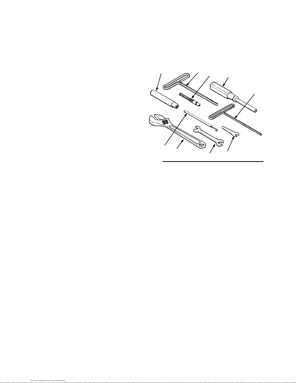
The following tools are supplied with the gun:
D 3/16 in. hex, T–handle hex key wrench (48)
D 3/32 in. hex, T–handle hex key wrench (47)
D 7/16 in. x 1/2 in. open end wrench (53)
D Pin vise (51) for cleaning pin supplied with Needle/
Nozzle Kits
D Nut driver (50)
D 1/4 in. open end wrench (52)
In addition, you will need to purchase an air valve hook
(O) to service the air valve, a pressing tool (P) to
service the piston (see Accessories, page 28), and a
small adjustable wrench (A). See Fig. 1.
You will also need a solvent flushing system to clean
the gun. See page 28 to order an accessory solvent
flush kit.
50
O
A
Fig. 1
48
53
51
50
47
52
6 307546
Page 7
Installation
)
Safety
For your safety, read all of the warnings and instructions in this manual, all system component manuals,
and the chemical manufacturer’s literature before
installing or operating the equipment. The warnings,
cautions and instructions are designed to help all
operators use this equipment with safety and confidence.
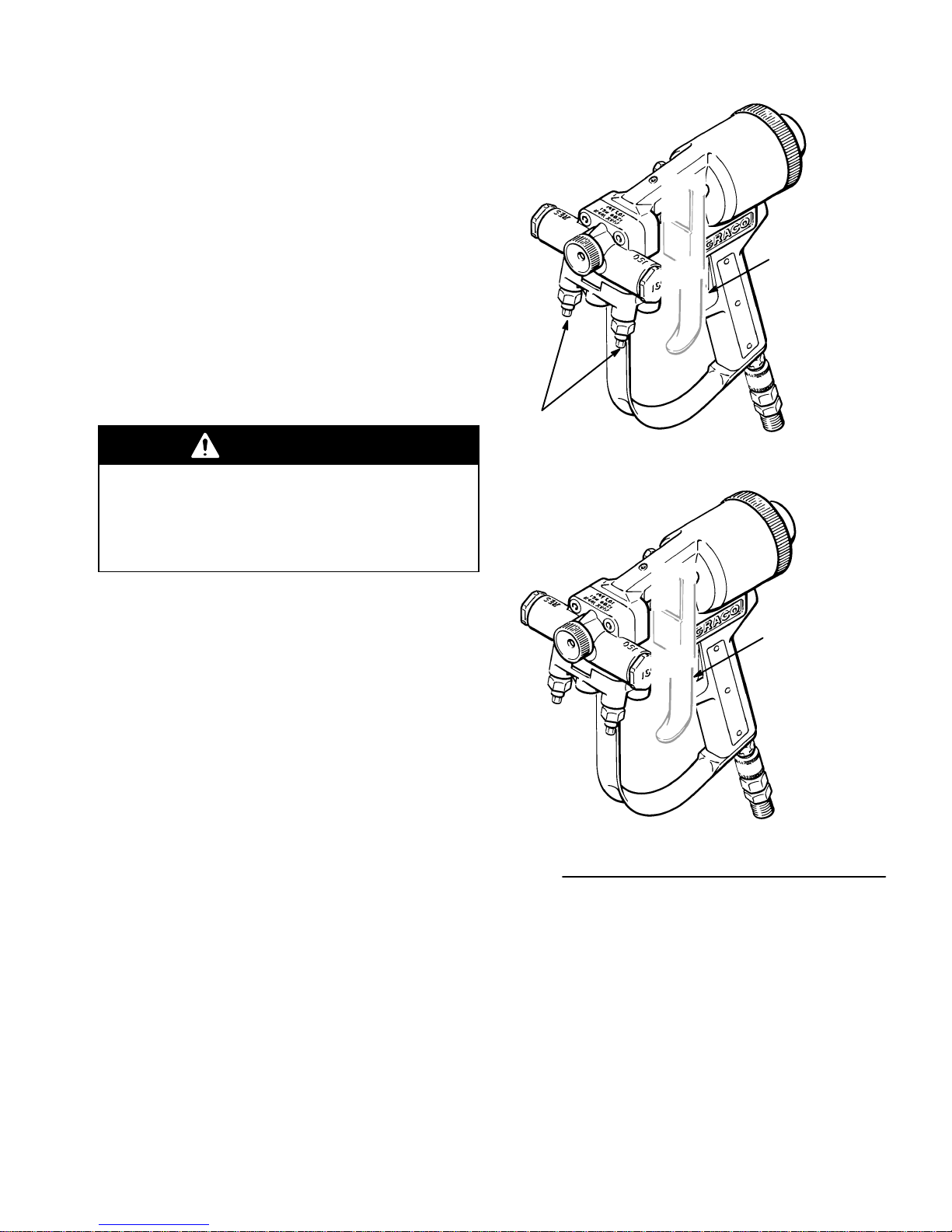
This gun has a trigger safety latch. To engage the
trigger safety latch (ON SAFE) and make the trigger
inoperative, pul out on the trigger safety latch (B) and
turn it so it is perpendicular to the gun body. To disengage the trigger safety latch (OFF SAFE) turn it so it is
parallel to the gun body. See Fig. 2.
WARNING
To reduce the risk of serious bodily injury from
injection of high pressure fluid, always engage the
trigger safety latch (ON SAFE) whenever you stop
spraying and close the needle valves (C) completely with the nut driver (50).
Trigger Safety (B
shown in ON
SAFE position
C
Grounding
When used with Graco Heated Hose, this gun is
grounded through hose connections. For other types of
hoses, be sure the hose you use is static grounded, or
attach a grounding wire between a metal part of the
gun and a true earth ground.
Optional O-rings
This gun is supplied with flourocarbon o-rings (44)
installed in the gun check valves, for use with methylene chloride solvent. A set of silicone o-rings (60) is
also included (not installed) for use with DMF (Dimethyl Formamide) and Cellosolver solvents.
Trigger Safety (B)
shown in OFF
SAFE position
Fig. 2
307546 7
Page 8
Installation
Installing a Needle/Nozzle Kit on a New Gun
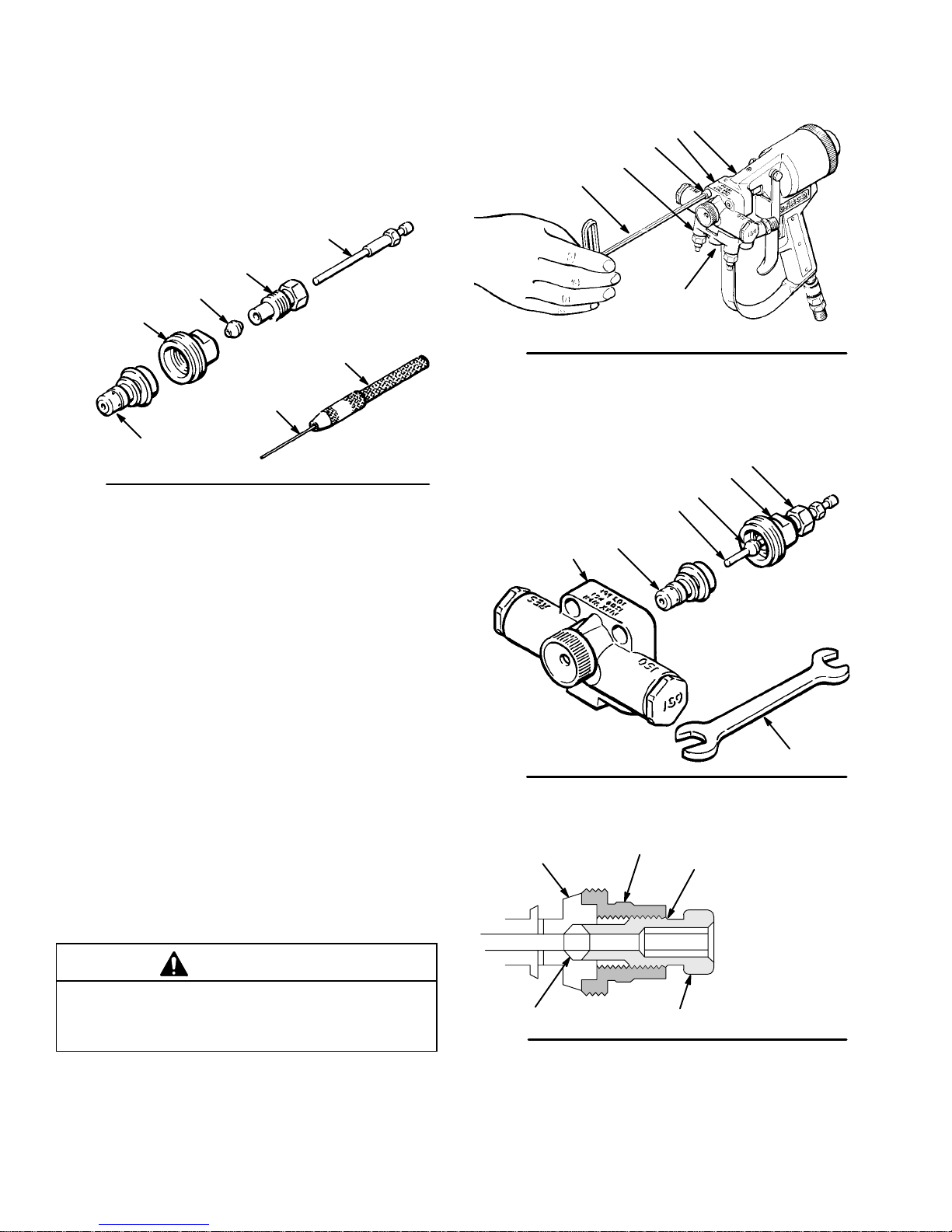
The needle/nozzle kit includes the parts shown in Fig.
3, except the pin vise (51) which holds the cleaning pin
(H), and the nozzle retainer (23).
KEY
23 Nozzle Retainer
51 Pin vise
D Needle
E Nozzle
F Packing
G Packing Nut
G
F
23
H
E
Fig. 3
To install the nozzle kit:
1. Use the 3/16 in. wrench (48) to remove the capscrew (7) from the fluid manifold (26) and to remove
the two capscrews (7) from the nozzle housing (2).
See Fig. 4.
D
51
KEY
1 Gun body
2 Nozzle housing
7 Capscrew
26 Manifold
48 Wrench
48
Fig. 4
KEY
2 Nozzle housing
23 Nozzle retainer
53 Wrench
D Needle
E Nozzle
F Packing
G Packing nut
2
26
1
2
7
7
G
23
F
D
E
2. Trigger the gun, then pull the housing straight off
the gun body (1).
3. Use the 1/2 in. end of the wrench (53) to remove
the nozzle retainer (23) from the back of the
housing (2). Refer to Fig. 5.
4. Insert the nozzle (E), tapered end first, into the
back of the housing. See Fig. 5.
5. Slide the packing nut (G), nozzle retainer (23), and
packing (F) onto the needle (D). Screw the packing
nut (G) into the nozzle retainer (23) until the top
threads of the packing nut is flush with the back of
the retainer. See Fig. 6.
6. Slide the needle assembly through the nozzle and
into the nozzle housing. Refer to Fig. 6.
CAUTION
Do not overtighten the nozzle retainer. This can
compact the nozzle and damage it or cause it to seat
improperly, resulting in spray pattern distortion.
Fig. 5
Fig. 6
53
E
23
F
Top thread of packing nut
(G) must be flush with
back of retainer (23)
KEY
23 Nozzle retainer
E Nozzle
G
F Packing
G Packing nut
8 307546
Page 9
Installation
7. Adjust the needle so it protrudes 1–3/4 in. (44 mm)
from the rear of the housing. See Fig. 7.
Fig. 7
8. Screw the nozzle retainer (23) snugly into the back
of the housing. Tighten using the open end wrench
(53). Torque to 25–35 in-lb (2.8–3.9 NSm).
9. Guide the needle of the nozzle assembly into the
front opening (J) of the gun body (1). The piston
(20) rod has a socket in the side of it which must
face down. Tilt the nozzle assembly up and swing
the ball of the needle (D) into the piston rod
socket. See Fig. 8.
10. Push the nozzle assembly further into the front
opening (J) until the back of the assembly meets
the gun body. Refer to Fig. 8.
11. Use the 3/16 in. wrench (48) to install the two
capscrews (7) firmly into the nozzle housing.
Torque to 40 in-lb (4.5 NSm). Refer to Fig. 9.
WARNING
To reduce the risk of serious bodily injury from fluid
injection, be sure the trigger safety latch (B) is
engaged (ON SAFE) before proceeding. Refer to
Fig. 2 on page 7.
12. Screw on the air cap (24). Connect an air line (K)
to the inlet bushing (9) of the gun. See Fig. 9.
43
7
KEY
1 Gun body
20 Piston
D Needle
J Front opening
Fig. 8
20
1
24
7
25
9
J
D
KEY
7 Capscrew
9 Bushing
24 Air cap
25 Manifold
32 Plug
40 O-ring
K Air line
32
K
Fig. 9
307546 9
Page 10

Installation
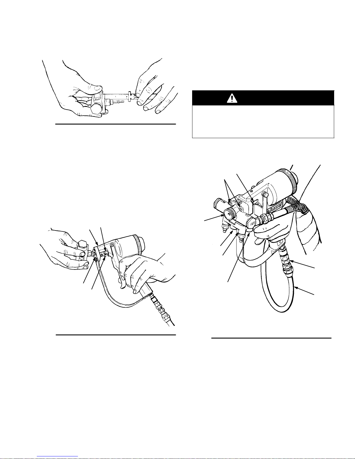
13. Use the 7/16 in. end of wrench (53) to adjust the
packing nut (G) until it is just snug. Don’t overtighten it. See Fig. 10.
14. Install the plastic shield (43) around the exposed
part of the needle assembly to keep foam over
spray from collecting on the needle. See Fig. 10.
15. Connect the fluid manifold (25) to the gun using
the 3/16 in. wrench (48) to tighten the capscrew
(7) firmly. Torque to 40 in-lb (4.5 NSm). See Fig.
10.
KEY
24 Air cap
53 Wrench
G
24
53
G Packing nut
Connecting Hoses
CAUTION
The Graco heated hoses and the fluid manifold (25)
inlets are labeled ISO and RES. Be very careful to
make only ISO to ISO and RES to RES connections.
Crossing fluid can damage the hoses and gun. Refer
to hose manual 307544.
1. The fluid hoses can be connected straight down
from the manifold or straight back from it as shown
in Fig. 10. Plug the manifold inlets that will not be
used with steel plugs (32).
2. Connect the fluid hoses to the manifold inlets. Be
sure the air hose (K) is connected to the gun. See
Fig. 10.
Fig. 10
10 307546
Page 11

Operation
Pressure Relief Procedure
WARNING
INJECTION HAZARD
The system pressure must be manually
relieved to prevent the system from
starting or dispensing accidentally. Fluid
under high pressure can be injected through the
skin and cause a serious injury. To reduce the risk
of an injury from injection, splashing fluid, or moving parts, follow the Pressure Relief Procedure
whenever you:
D are instructed to relieve the pressure,
D stop dispensing,
D check or service any of the system equipment,
D install or clean the nozzle.
1. Engage the spray gun trigger latch.
2. Shut off the air to the feed pumps.
3. Turn off the electric motor switch in a hydraulic
system.
4. Turn off the air to the proportioning system in an
air-powered system.
5. Close the gun manifold needle valves.
6. Disengage the trigger safety latch, trigger the gun
to relieve pressure, and engage the trigger safety
latch again.
7. Open both fluid filter drain valves, having a container ready to catch the draining fluid.
8. If you are working on any part of the heater, shut
off the main electrical power to the heater.
307546 11
Page 12

Operation
1. Adjust cleanoff air as instructed in the next
column. Be sure the needle valves (C) are closed.
See Fig. 11.
2. Adjust the fluid temperature. Most foam fluids
are designed for spraying at 100_ to 140_F (38_ to
60_C). Adjust the heater and hose controls to the
chemical manufacturer’s recommended temperature. If no temperature is specified, start at 115_F
(43_C).
Refer to manual 307543 for specific instructions on
adjusting and operating the Foam-Cat Heater and
Heated Hose Controls.
3. Adjust the pump outlet pressure to 1000 psi (70
bar). This is adequate for most spray applications.
If more fluid flow is needed at that pressure, try
using a larger fluid nozzle. Refer to the Nozzle
Performance Chart on page 5. Increasing the
fluid pressure could distort the spray pattern.
4. Allow the fluid to heat thoroughly. The Graco
Heater and Heated Hose requires 15 minutes
warm up time.
Adjusting Cleanoff Air
Each time the gun’s trigger is released, the needle
purges the nozzle and the cleanoff air blows the
purged foam off the tip of the nozzle. Be sure the
cleanoff air is properly adjusting to avoid a build up of
foam on the nozzle or under the air cap.
WARNING
To reduce the risk of an injection injury, follow this
procedure before adjusting the cleanoff air:
Engage the trigger safety (40), close the needle
valves (64), disengage the trigger safety, and
trigger the gun to relieve the fluid pressure. Engage
the trigger safety again.
1. Screw in the air adjusting setscrew (19) using the
3/32 in. wrench (47), until no air or almost no air is
escaping. See Fig. 11.
2. Regulate the air to the gun to 100 psi (0.7 MPa, 7
bar).
5. Spray for several seconds in cold weather to
bring thoroughly warmed fluid to the gun. Release
the gun trigger safety latch, open the needle
valves (C), and aim the gun at a large piece of
cardboard when testing spraying.
CAUTION
Open the RES side first to help prevent nozzle
damage.
6. Test for proper foam texture. Trigger the gun in
one second intervals to test the spray pattern. A
good spray pattern should be round and well
atomized and it should harden with a fairly smooth
surface. Refer to the chart on page 4 for the
proper size of pattern and spraying distance for the
nozzle being used.
7. Release the gun trigger at least once a minute
while spraying if you use a no–release triggering
method. This actuates the mechanical purger and
avoids fluid buildup on the nozzle tip and air cap.
3. Back off the setscrew two turns as a test setting.
4. If the air appears to affect the spray pattern, screw
in the setscrew another turn. If build up behind the
air cap occurs, back off the setscrew about 1/2
turn at a time.
NOTE: Use the minimum amount of air needed to
clean the nozzle. Too much air could affect the spray
pattern.
KEY
19 Setscrew
47 Wrench
C Needle valves
19
47
CAUTION
Do not nick or scratch the nozzle tip as this could
distort the spray pattern.
12 307546
RES
C
Fig. 11
Page 13

Spray Pattern Adjustment
Effects of Fluid Temperature and Pressure
This section will help you determine how fluid temperature and pressure affect the spray pattern, and what
adjustment can be made to correct a poor spray
pattern. Since fluid temperature and pressure, and the
nozzle, all affect the spray pattern, experimenting will
help you learn how to control these variables.
Changing the fluid temperature affects viscosity and
reaction time of the fluid. Raising the temperature
reduces the viscosity and produces a wider spray
pattern with finer atomization; it has much the same
effect as raising the fluid pressure.
As the fluid temperature gets too high, the pattern
becomes square with less foam in the center. Too high
a temperature can also cause the chemical reaction to
occur before the foam hits the spraying surface, which
causes an undesirable rough surface.
Observing the Effects of Varying Fluid
Temperature and Pressure
It is helpful to observe the effects of varying the fluid
pressure and temperature. Raising the fluid temperature has about the same affect as raising the fluid
pressure.
1. With fluid temperature set at 115_F (43_C), test
the spray pattern at 300 psi (2.1 MPa, 21 bar).
Increase the pressure in 100 psi (0.7 MPa, 7 bar)
increments up to 1000 psi (7 MPa, 70 bar). In the
lower pressure range, the pattern will be narrow
and coarse. As the pressure is raised, the pattern
becomes wider and finer. When the pressure
becomes too high, the pattern becomes square
and light in the middle.
2. Now, lower the fluid pressure and raise the fluid
temperature in 5_ increments up to 135_. Notice
that the spray pattern is affected much the same
by fluid temperature as it is by fluid pressure.
3. To minimize over spray and fogging, always use
the lowest fluid pressure possible to get the
desired spray pattern.
4. The output pressure of both displacement pumps
should be within 150 psi (1.1 MPa, 10.5 bar) of
each other to keep the viscosity of the ISO and
RES similar. To change the pressure in only one
displacement pump, adjust the temperature.
To raise the fluid pressure, decrease the fluid
temperature.
To lower the fluid pressure, increase the fluid
temperature.
About Surface Texture
The quality of foam developed is reflected in its
surface texture. There are several causes of poor
surface texture, including improper equipment adjustments. Descriptions of surface textures and recommendations on how to adjust the equipment to improve
the texture are on the following pages.
About Poured Foam texture
Poured foam should have no dark or soft spots. The
surface should be relatively smooth with only small
ripples. There should be no blow holes larger than 1/4
in. (6 mm) diameter.
307546 13
Page 14

Surface Texture Descriptions
Smooth Surface Texture
Description
Wavy texture.
Equipment Adjustments
None; has good surface texture.
Orange Peel Texture
Description
Fine texture; like the skin of an orange.
Equipment Adjustments
None; has good surface texture.
Coarse Orange Peel Texture
Description
Surface texture has nodules and valleys of similar size
and shape.
Equipment Adjustments
More flow-out time needed before the rise and cream
time.
Atomized material too coarse. Increase fluid pressure.
If condition persists, increase fluid temperature.
Try holding the gun further away from the spray surface.
Popcorn Surface Texture
Description
Linear surface pattern; forms sharp valleys and overhangs.
Equipment Adjustments
More flow-out time needed before the rise and cream
time.
Slow the foam reaction time by lowering fluid temperature; since this increases the viscosity of the chemicals, the fluid pressure must be raised to maintain
good atomization.
This type of surface pattern can also be caused by
spraying a second lift of foam on top of the first lift
while it is still creaming and rising.
Isocyanate-Rich Surface Texture
Description
Foam is dark in color; does not become tack-free in
the time specified by the chemical manufacturer.
Caused by lack of resin in the foam.
Equipment Adjustments
1. Refill or replace the resin supply.
2. Clean or replace the resin feed pump.
3. Clean the intake filter of the resin proportioning
pump.
4. Clean or repair the resin proportioning pump.
Resin-Rich Surface Texture
Description
Foam has appearance of white shaving cream; does
not become tack-free in the time specified by the
chemical manufacturer. Caused by lack of isocyanate
in the foam.
Equipment Adjustments
1. Refill or replace the isocyanate supply.
2. Clean or replace the isocyanate feed pump.
3. Clean the intake filter of the isocyanate proportioning pump.
4. Resin temperature is too high. Resin is frothing in
the nozzle. Reduce resin temperature.
14 307546
Page 15

Replacing the Needle/Nozzle Assembly
WARNING
PRESSURIZED EQUIPMENT HAZARD
To reduce the risk of serious bodily injury including
fluid injection, splashing in the eyes or on the skin,
follow the Pressure Relief Procedure whenever
you:
D are instructed to relieve the pressure,
D stop spraying,
D check or service any of the system equipment,
D or install or clean the spray nozzle.
1. Have a solvent pail ready to clean the old parts.
2. Solvent flush the gun as instructed in Flushing
steps 1–9 on page 19.
3. Disconnect the solvent manifold.
4. Remove the two capscrews (7) using the 3/16 in.
wrench (48). See Fig. 12. With the air connected
to the gun, hold the gun with the nozzle housing
straight down and briefly trigger the gun to push
the nozzle housing away from the gun body.
Disconnect the air line.
KEY
7 Capscrew
25 Manifold
50 Nut driver
B Safety latch
C Needle valves
Fig. 12
7
25
B
C
50
7
20
5. Tilt the nozzle housing up and disengage the
needle ball from the piston (20) rod. Remove the
housing from the gun. See Fig. 13.
6. Pull the needle out from the rear of the nozzle
assembly. Use the 1/2 in. end of the wrench (53)
to unscrew and remove the nozzle retainer (23).
Remove the air cap (24). Place all parts in the
solvent. Refer to Fig. 5 on page 8.
7. Use your fingers or a soft tool such as pencil
eraser to push on the front of the nozzle (E) and
pop it out the rear of the housing. Place the nozzle
in solvent, being careful to keep it separated from
the other parts to avoid damage. See Fig. 14.
NOTE: If the nozzle impingers holes are blocked, refer
to the section, Cleaning the Nozzle on page 17.
CAUTION
Do not use a sharp tool to remove the nozzle.
Scratches on the edge of the nozzle may distort the
spray pattern. Scratches or nicks on the raised
surfaces prevent the nozzle from sealing properly in
the nozzle housing. An improper seal can result in
fluid crossover which clogs the gun passages.
KEY
20 Piston
Fig. 13
KEY
E Nozzle
Fig. 14
E
307546 15
Page 16

Replacing the Needle/Nozzle Assembly
8. Check the interior surfaces of the nozzle housing
(2). The tapered “steps” inside the nozzle housing
must be free of fluid buildup. Soak the housing in
solvent to soften the foam, then use a soft bristled
brush to gently clean the interior surfaces.
9. Remove the check valve housings (45, 46) and
strainers (34) from the nozzle housing and clean in
solvent. Then reinstall the parts. See page 15.
10. Install the needle/nozzle assembly as instructed in
steps 4–15 on pages 8–10.
11. Reconnect the foam manifold.
46
KEY
2 Nozzle housing
34 Strainer element
45 ISO check valve housing
46 RES check valve housing
Fig. 15
2
34
45
16 307546
Page 17

Cleaning the Nozzle
Foam Spraying Nozzles
Nozzle
Bore Dia.
in. (mm)
0.125 (3.18)
0.114 (2.90)
0.102 (2.54)
0.089 (2.26)
0.073 (1.85)
0.083 (2.11
0.060 (1.52)
Cleaning
Pin Dia.
in. (mm)
0.033 (0.84)
0.029 (0.75)
0.026 (0.66)
0.024 (0.61)
0.018 (0.46)
0.020 (0.51)
0.018 (0.46)
Cleaning Pin
Part No.
106542
106543
106548
106545
106546
106547
106546
Foam Pouring Nozzles
0.187 (4.75)
0.073 (1.85)
1. Solvent flush the gun as instructed in Flushing,
steps 1–9 on page 19. Disconnect the solvent
manifold.
2. Remove the nozzle from the nozzle housing as
instructed on page 15.
3. Insert the correct impinger cleaning pin (H) in the
pin vise (51) so that it protrudes about 1/2 in. (13
mm). Tighten the vise jaws.
0.029 (0.75)
0.020 (0.51)
106543
106547
CAUTION
Each needle/nozzle kit has a specially-sized impinger
cleaning pin (H). Be sure to use the correct pin to
avoid damaging the nozzle. Refer to the tables
above.
4. Clean the rear impinger holes (M) of the nozzle
(E) first. From the tip end of the nozzle, look
through the nozzle while inserting the cleaning pin
(H) into the rear impinger holes. See Fig. 16.
5. Insert the needle (D) through the large end of the
nozzle and push out any debris.
6. Repeat Steps 4 and 5 to be sure the rear impinger
holes are clean.
KEY
51 Pin vise
D Needle
E Nozzle
H Cleaning pin
M Rear impinger holes
N Front impinger holes
51
H
N
M
E
D
Fig. 16
7. Now clean the front impinger holes (N). On the
spray nozzles these impinger holes are not on the
centerline of the nozzle, but are just off center. On
pour nozzles these holes are on the centerline. It is
important that the pin be inserted at the same
angle that the impinger hole is bored in order to
clean it properly.
Look through the nozzle from the tip end. Insert the pin
(H), pushing it through the impinger hole and into the
center of the nozzle. But do not push the pin all the
way through which will scratch the interior of the
nozzle. See Fig. 16.
The rear impinger holes are directly on the centerline
of the nozzle. Push the pin through the impinger hole
and into the middle of the nozzle. Don’t push the pin all
the way through or scratch the interior of the nozzle.
Clean each of the rear holes.
8. Insert the needle (D) through the large end of the
nozzle and push out any debris.
9. Repeat Steps 7 and 8 to be sure the impinger
holes are clean.
307546 17
Page 18

Maintenance
WARNING
PRESSURIZED EQUIPMENT HAZARD
To reduce the risk of serious bodily injury including
fluid injection, splashing in the eyes or on the skin,
follow the Pressure Relief Procedure whenever
you:
D are instructed to relieve the pressure,
D stop spraying,
D check or service any of the system equipment,
D or install or clean the spray nozzle.
Fluid Buildup on Nozzle
A build up of fluid on the nozzle and under the air cap
can cause an irregular spray pattern. If that happens,
follow the Pressure Relief Procedure on page 11.
Then thoroughly clean the air cap and nozzle. Be sure
that the cleanoff air is properly adjusted, also.
Fluid Buildup on Needle
If build up of fluid causes the needle (D) to stick, use
the 1/4 in. open end wrench (52) on the hex of the
needle and rotate to free it.
KEY
43 Needle shield
50 Nut driver
B Safety latch
C Needle valves
C
50
Fig. 17
43
Keeping the Gun Clean While Spraying
Coat it with grease or cover it with a plastic bag. Be
sure the plastic shield (43) is in place around the
exposed area of the needle. See Fig. 17.
A dirty needle can be cleaned by buffing it lightly with
bronze wool or very fine steel wool.
Cleaning the Fluid Manifold
B
Clean the manifold with solvent and a brush whenever
it is removed from the gun to keep fluid from hardening
on it.
Shutdown
WARNING
To reduce the risk of serious bodily injury from fluid
injection or splashing fluid in the eyes or on the
skin, engage the trigger safety latch (B) and close
the needle valves (C) whenever you stop spraying.
See Fig. 2, page 7.
For overnight shutdown:
1. Follow the Pressure Relief Procedure on page
11, and Flushing, steps 1–9 on page 19.
2. Disconnect the solvent manifold and store the gun.
18 307546
Page 19

Flushing
WARNING
PRESSURIZED EQUIPMENT HAZARD
To reduce the risk of serious bodily injury including
fluid injection, splashing in the eyes or on the skin,
follow the Pressure Relief Procedure whenever
you:
D are instructed to relieve the pressure,
D stop spraying,
D check or service any of the system equipment,
D or install or clean the spray nozzle.
CAUTION
Thorough flushing of the nozzle and nozzle housing
is essential each day to reduce fluid buildup which
will quickly ruin the nozzle.
KEY
C Needle valves
R Ground wire and clamp
C
R
Fig. 18
4. Use the lowest possible pressure and hold the gun
firmly to a grounded metal pail when flushing. See
Fig. 18.
5. Flush the gun for 10 seconds.
6. Engage the trigger safety latch.
Graco recommends using a power flushing method,
such as the Solvent Power Flush Kit, Part No.
218669. If you use this kit, refer to instruction manual
307692 for specific flushing procedure.
Use this flushing procedure when a Graco Solvent
Flush Kit is not available.
1. Remove the foam manifold capscrew (7) using the
3/16 in. wrench (68), then disconnect the manifold.
See Fig. 4, page 8.
2. Connect a solvent manifold to the gun; tighten the
capscrew.
3. Open the needle valves (C).
WARNING
7. Turn off the solvent system.
8. Follow the Pressure Relief Procedure on page
11.
46
KEY
34 Strainer element
45 ISO check valve housing
46 RES check valve housing
Fig. 19
9. Remove and clean the check valve housings (45
and 46) and strainers (34) in solvent. See Fig. 19.
10. Remove the solvent manifold and reconnect the
foam manifold.
NOTE: Whenever the foam manifold is removed, clean
it with solvent and a brush.
34
45
To reduce the risk of static sparking which could
result in fire or explosion and serious bodily injury
and property damage:
D Be sure all equipment used in the flushing
operation is properly grounded.
D Never flush gun while standing on or near a
surface where foam has been applied.
CAUTION
Use a solvent which is compatible with the check
valve o-rings. See page 7.
Never immerse the entire gun in solvent.
These steps help prevent damage to the gun o-rings
and seals.
307546 19
Page 20

Troubleshooting
WARNING
To reduce the risk of serious injury, whenever you
are instructed to relieve pressure, always follow the
Pressure Relief Procedure on page 11.
D Relieve the pressure before checking or servicing
the equipment.
D Check all possible problems and causes before
disassembling the pump.
Problem
Coarse atomization Fluid temperature too low. Increase temperature.
Fingering in spray pattern Fluid temperature too low. Increase temperature; use smaller
Square spray pattern with hollow
center
Triangular spray pattern with hollow center
Round spray pattern with hollow
center
Middle of spray pattern dense
Air valve leaks O-rings exposed to solvent. Replace o-rings. See page 24. Do not
Split spray pattern Nozzle impinger hole blocked. Clean nozzle. See page 17.
Distorted, irregular spray pattern Too much cleanoff air. Reduce air. See page 12.
Light-colored foam Too little ISO.
Dark-colored foam Too little RES.
Cause Solution
nozzle.
Fluid temperature too high or fluid
pressure too high.
Fluid temperature too high and a
nozzle impinger hole blocked.
Too much fluid flow. Reduce fluid pressure or tempera-
Fluid buildup on walls of impinger
holes.
Too little fluid flow. Increase fluid flow and/or tempera-
ISO check valve screen blocked. Remove check valve and clean
Decrease temperature and/or reduce
fluid pressure.
Decrease temperature; clean nozzle.
See page 17.
ture.
Clean nozzle. See page 17.
ture.
strainer. See step 9, page 16.
immerse gun in solvent.
Check and clean check valve strainers. See step 9, page 16.
Check and clean proportioning pump
filter screens.
Check and refill ISO fluid supply.
Check proportioning pump ratios.
Check and clean check valve strain-
ers. See step 9, page 16.
Check and clean proportioning pump
filter screens.
Check and refill ISO fluid supply.
Check proportioning pump ratios.
20 307546
Page 21

Troubleshooting
Problem Cause Solution
Gun operates slowly when triggered
Needle won’t pull back when gun
is triggered
Inbound air pressure too low. Increase air, but do not exceed 120
psi (0.8 MPa, 8 bar), since damage to
air valve o-rings may result.
Air valve leaking air. Check for worn, damaged, or over-
compressed o-rings on valve spool
and repair as needed. See pages 24.
Center spacer (12) of air valve compressed.
Air leaking past piston at rear of gun. Check piston o-rings and replace as
Blocked air passages. Check air passages for dried fluid
Foam over spray built up on needle. Clean. See page 18.
Inbound air pressure too low. Increase air, but do not exceed 120
Needle stuck in nozzle. Use 1/4 in. open end wrench to rotate
Piston o-ring (40) damaged, causing
imbalance of pressure between front
and rear chambers.
Check; replace if compressed. See
pages 24.
needed. See page 23.
foam and/or broken o-ring pieces;
clean as needed.
psi (0.8 MPa, 8 bar), since damage to
the air valve o-rings may result.
hex of needle to free. Clean. See
page 18. Check and clean or replace
nozzle.
Check; repair. See page 23.
307546 21
Page 22

WARNING
Service
9. Continue screwing the stem into the housing (28)
all the way to the shoulder.
Follow the Pressure Relief Procedure on page
11, then disconnect the gun from the manifold
before proceeding.
Needle Valves
NOTE: Repair Kit 217360 is available. See page 28.
1. Open the needle valves (C) completely – 3 1/2
turns.
2. Use a wrench (A) to unscrew the valve housing
(28). Refer to Fig. 20.
3. Hold the valve housing with a wrench (A). Turn the
(50) clockwise to free the needle valve stem (29).
See Fig. 21.
4. Use a pick to remove the backup washer (31) and
o-ring (17). See Fig. 22.
5. If needed, soak the valve housing (28) in solvent to
remove fluid buildup.
10. Screw the housing into the manifold (26). Don’t
exceed 80 in-lb (9 NSm) of torque.
11. Finish screwing the stem in gently – it doesn’t
require much torque.
KEY
28 Valve housing
C Needle valve
28
C
Fig. 20
KEY
29 Stem &
seal assembly
50 Nut driver
A Wrench
50
A
29
Fig. 21
6. Install the backup washer (31) on the stem and
screw the stem into the valve housing (28) to
“size” the washer. Unscrew the stem.
7. Install the o-ring (17) on the stem. See Fig. 22.
8. Holding the valve housing, screw the stem
assembly into it. It will require a couple of turns
before it starts to engage in the housing far
enough to use the nut driver.
KEY
17 O-ring
26 Manifold
28 Housing
29 Stem &
seal assembly
31 Backup washer
Fig. 22
26
29
17
31
28
22 307546
Page 23

WARNING
Service
4. Clean all parts thoroughly, replacing parts as
needed, and then reassemble.
Follow the Pressure Relief Procedure on page 11
before proceeding.
Piston (See Fig. 23)
1. Relieve pressure.
2. Remove the nozzle housing assembly as
instructed in Replacing the Needle/Nozzle As-
sembly on page 15.
3. Remove the cylinder cap (21), o-ring (39), spring
(15) and piston (20).
4. If fluid crossover has occurred, remove the bearing
(22) to clean the piston passage as follows: insert
the large end of the accessory pressing tool (P)
through the front end of the gun and press out the
piston rod bearing (22).
5. Replace the o-ring (41), then reinstall the bearing,
if it was removed, through the rear of the gun. Use
the small end of the pressing tool (P) to press it
into place.
KEY
15 Spring
20 Piston
21 Cylinder cap
22 Bearing
39 O-ring
40 O-ring
41 O-ring
P Pressing tool
40
41
22
Fig. 23
46
21
39
15
20
P
6. If the o-ring (40) around the piston shows signs of
wear or damage, replace it. Then reinstall the
piston, spring, o-ring and cylinder cap.
NOTE: The cylinder cap should fit snugly against the
rear of the gun.
Check Valve (See Fig. 24)
1. Relieve pressure.
2. Unscrew the check valve housings (45, 46).
3. If the check valve assembly (61) cannot be
removed easily, insert a pick (such as a dentist’s
pick) into the slot in the check valve housing and
push the seat (36) out of the housing.
KEY
34 Strainer
45 RES Check Valve Housing
46 ISO Check Valve Housing
61 Check Valve Assembly
Fig. 24
34
61
45
307546 23
Page 24

Service
Air Valve (See Fig. 25)
1. Relieve pressure.
2. Remove the nozzle housing assembly as
instructed in Replacing the Needle/Nozzle As-
sembly on page 15.
3. Use the 1/2 in. end of wrench (53) on the flats of
the stem guide (10) to unscrew it.
4. Use your fingers to pull out the valve pin (13).
5. To remove the valve spool (14) and spring (16) tilt
the gun forward and tap the gun against your
hand. The spring is very small – be careful not to
lose it.
NOTE: Use the accessory air valve hook (O) to pull
out the air valve spacers (11,12). To use it, insert the
hook into the valve, hook one of the holes in the
spacer and pull it out.
6. Use the hook (O) to pull the first spacer (11A) out
just 3/32 in. (2.8 mm). Push the spacer back into
the valve and remove the tool. This action will free
the first o-ring (18A). Use the hook to remove the
o-ring.
7. Insert the hook (O) again and remove the first
spacer. Notice the direction this spacer faces.
8. Remove the next o-ring (18B) with the hook.
9. Remove the next spacer (12) by shaking it out or
using the hook if it is stuck.
10. Remove the next o-ring (18C) with the hook.
11. Remove the last spacer (11B) by shaking it out or
using the hook if it is stuck. Again, notice the
direction the spacer faces.
12. Use the hook to remove the last o-ring (18D).
13. If foam has backed up into the air valve cavity,
remove the two setscrews (6, 33) on either side of
the valve cavity and clean the holes with a soft
wooden stick. Never use power tools!
14. Reassemble the air valve using all new o-rings
which have been lubricated with lithium grease.
Use the eraser end of a pencil to guide the o-rings
into the cavity and make sure they seat flatly.
15. Install the first o-ring (18D) and then a spacer
(11B) with the small diameter facing out.
CAUTION
The direction the first and last spacer face out is
critical. Although they are identical spacers, the small
diameters must face each other. See Fig. 24.
16. Install the next o-ring (18C), the U-shaped spacer
(12), another o-ring (18B), the last spacer – with
the small diameter facing in – and the last o-ring
(18A).
17. Gently screw the stem guide (10) into the valve by
hand. Then use the wrench to just snug the stem;
this will stack the o-rings properly.
24 307546
Page 25

CAUTION
Be careful not to wrench the stem guide (10) too
tightly to avoid damage to the air valve.
18. Remove the stem guide and drop in the new
spring (16), making sure it goes all the way into the
hole in the back of the valve cavity.
KEY
10 Stem guide
11 Spacer
12 U-shaped valve spacer
13 Pin
14 Spool
16 Spring
17 O-ring
18 O-ring
57 O-ring
O Pick
O
18A*
17*
Service
19. Install the valve spool (14) and valve pin (13), then
the stem guide (10). Tighten the stem guide until it
is just snug; don’t overtighten.
20. If the setscrews (6,33) were removed from either
side of the valve cavity, reinstall them using
PTFE tape on the threads.
21. Reinstall the trigger.
18D*
18C*
18B*
16
33
11B
6
Small diameter
Fig. 25
57
10
18
13
11A
12
Small diameter
14
NOTE: DO NOT allow o-ring to seat in grooves with passageways
307546 25
Page 26

Ref 25 Manifold Assy.
Includes items 26–32
and two of item 17.
7
24
58
TAP
INTO
PLACE
29
Parts
NEEDLE/NOZZLE DETAIL
See back cover for ordering.
Items 23 and 43 included
2
23
34
35
36
37
38
44 or 60
45 or 46
27
26
with gun only.
43
NEEDLE
PACKING NUT
PACKING
REF 23
NOZZLE
17
31
28
19
33
32
7
21
39*
15
20
4
PRESS FIT INTO GUN BODY (1)
22
40*
41*
5
1
42
54
6
8
9
THE TOOLS SUPPLIED WITH THE GUN
(ITEMS 47 TO 53) ARE PICTURED ON
P AGE 6.
33
16
18*
3
18*
10
57*
26 307546
13
17*
18*
14
11
6
11
12
Air Valve
Includes items
10 to 14, 16,
three of 17,
3 or 18 and 57
Page 27

Model 217373, Series E
Includes items 1 to 61
Parts
REF
NO. PART NO. DESCRIPTION QTY
1 217459 BODY, gun 1
2 178663 HOUSING, nozzle 1
3 178584 TRIGGER 1
4 178682 PIN, trigger 1
5 203953 CAPSCREW, hex hd;
10–24 x 0.375 in. 1
6 102279 SETSCREW, soc hd;
8–32 x 0.188 in. 1
7 101682 CAPSCREW, soc hd;
1/4–20 x 0.625 in. 3
8n 106552 COUPLER, air line 1
9 100030 BUSHING; 1/8 npt(m) x 1/4 npt(f) 1
10 178654 GUIDE, stem 1
11 178653 SPACER, valve 2
12 178652 SPACER, valve, u-shaped 1
13 178650 PIN, air valve 1
14 178651 SPOOL, valve 1
15 178671 SPRING, compression, piston 1
16 106561 SPRING, compression, air valve 1
17* 106560 O-RING; Vitonr 5
18* 106559 O-RING; Viton 5
19 106538 SETSCREW, soc hd;
10–32 x 0.5 in. 1
20 178649 PISTON 1
21 178648 CAP, cylinder 1
22 178647 BEARING, piston 1
23 178646 RETAINER, nozzle 1
24 178642 CAP, air 1
25 221177 MANIFOLD ASSEMBLY; includes
items 26–32 and two of 17 1
26 183598 .MANIFOLD, fluid 1
27 191872 .ADAPTER;
1/4 npsm(f) x 1/8 npt(m) 2
28 178657 .HOUSING, valve 2
29n 218628 .STEM and SEAL ASSEMBLY 2
31 106558 .WASHER, backup; PTFE 2
32 100139 .PLUG, pipe, hdls; 1/8 npt(f) 2
33 100002 SETSCREW, soc hd;
1/4–20 x 0.25 in. 1
REF
NO. PART NO. DESCRIPTION QTY
34n 178585 ELEMENT, strainer; SST; 80 mesh2
35 178660 STEM, check valve 2
36 178659 SEAT, check valve; Delrinr 2
37 106562 SPRING, compression 1
38 178658 RETAINER, spring 1
39* 106557 O-RING; Viton 1
40* 106556 O-RING; Viton 1
41* 106555 O-RING; Viton 1
42 102817 SCREW, drive 3
43 178586 SHIELD 1
44 110188 O-RING; flourocarbon; brown color;
for methylene chloride solvents 2
45 180964 HOUSING, check valve, ISO 1
46 180965 HOUSING, check valve, RES 1
47 106571 WRENCH, hex; 3/32 in. 1
48 106572 WRENCH, hex; 3/16 in. 1
50 106540 TOOL, nut driver 1
51 106550 VISE, pin 1
52 107015 WRENCH, open end; 1/4 in. 1
53 106539 WRENCH, open end;
7/16 in. x 1/2 in. 1
54 178587 PLATE, warning 1
55Y 178695 TAG, warning (not shown) 1
57* 106551 O-RING; Viton 1
58 179716 GASKET, housing 2
59 218756 O-RING KIT, check valve; includes
items 44 and 60 (not installed) 1
60 110189 .O-RING; silicone; rust colored; for
DMF and Cellosolver solvents 2
61 218627 CHECK VALVE ASSEMBLY;
includes items 35–38 1
* These parts are included in Repair Kit 217360,
which may be purchased separately.
n Keep these spare parts on hand to reduce down
time.
Y Replacement Danger and Warning labels, tags, and
cards are available at no cost.
307546 27
Page 28

Must be purchased separately.
Accessories
Foam Flush Kit 218669
120 psi (0.8 MPa, 8 bar) Maximum Working Pressure
For solvent flushing the Foam-Cat gun.
Air Valve Hook 178583
Essential for removing air valve o-rings and spacers.
Pressing Tool 178581
For servicing piston.
Air Valve Repair Kit 217360
Part No. Description Qty.
106560 O-RING; Viton 3
106559 O-RING; Viton 5
106557 O-RING; Viton 1
106556 O-RING; Viton 1
106555 O-RING; Viton 1
106551 O-RING; Viton 1
28 307546
Page 29

Technical Data
N
Packi
Packi
Category Data
Maximum working pressure 1500 psi (10.5 MPa, 105 bar)
Maximum air working pressure 120 psi (0.8 MPa, 8 bar)
Air inlet sizes 1/4 npt(m) with bushing; 1/8 npt(f) without bushing
Fluid inlet sizes 1/4 npsm(m) with adapter; 1/8 npsm(f) without adapter
Strainer element 80 mesh (177 micron)
Wetted parts Stainless steel, Carbon steel, Brass, PTFE, Viton, Delrin,
Fluorocarbon
Vitonr, and Delrinr are registered trademarks of the DuPont Company.
Nozzle Kit Summary
Needle
1
Kit No.
217420* 0.125 (3.18) 217364 178633 178624 178615 106542 0.033 (0.84)
217421* 0.114 (2.90) 217365 178634 178625 178616 106543 0.029 (0.75)
217423* 0.089 (2.26) 217367 178636 178627 178618 106545 0.024 (0.61)
217424* 0.073 (1.85) 217368 178637 178628 178619 106546 0.018 (0.46)
217425* 0.083 (2.11) 217369 178638 178629 178620 106547 0.020 (0.51)
217426* 0.102 (2.59) 217366 178635 178626 178617 106548 0.026 (0.66)
217428* 0.060 (1.52) 217371 178640 178631 178622 106546 0.018 (0.46)
217427{ 0.187 (4.75) 217370 181515 178630 178621 106543 0.029 (0.75)
220616{ 0.073 (1.85) 217368 183117 178628 178619 106547 0.020 (0.51)
* Use for foam spraying applications.
{ Use for pouring applications.
NOTES:
1
Each kit includes a needle, nozzle, packing, packing nut, and cleaning pin. Each part may be ordered separately or as a kit.
2
Select a nozzle that will not exceed the maximum recommended flow rate of your foam spray system at the desired working
pressure. Too high a flow may exceed the performance capabilities of the foam heater and other spray components, causing
poor foam development and equipment problems.
3
The last three digits of the part no. are stamped on the needle, nozzle, and packing nut to help you identify the size.
Diameter
in. (mm)
Part No.
3
ozzle Part
2, 3
No.
ng
Part No.
ng Nut
Part No.
3
Cleaning Pin
Part No.
Diameter
in. (mm)
307546 29
Page 30

Graco Standard Warranty
Graco warrants all equipment manufactured by Graco and bearing its name to be free from defects in material and workmanship on the
date of sale by an authorized Graco distributor to the original purchaser for use. With the exception of any special, extended, or limited
warranty published by Graco, Graco will, for a period of twelve months from the date of sale, repair or replace any part of the equipment
determined by Graco to be defective. This warranty applies only when the equipment is installed, operated and maintained in accordance with Graco’s written recommendations.
This warrant y does not cover, and Graco shall not be liable for general wear and tear, or any malfunction, damage or wear caused by
faulty installation, misapplication, abrasion, corrosion, inadequate or improper maintenance, negligence, accident, tampering, or substitution of non–Graco component parts. Nor shall Graco be liable for malfunction, damage or wear caused by the incompatibility of
Graco equipment with structures, accessories, equipment or materials not supplied by Graco, or the improper design, manufacture,
installation, operation or maintenance of structures, accessories, equipment or materials not supplied by Graco.
This warranty is conditioned upon the prepaid return of the equipment claimed to be defective to an authorized Graco distributor for
verification of the claimed defect. If the claimed defect is verified, Graco will repair or replace free of charge any defective parts. The
equipment will be returned to the original purchaser transportation prepaid. If inspection of the equipment does not disclose any defect
in material or workmanship, repairs will be made at a reasonable charge, which charges may include the costs of parts, labor, and
transportation.
THIS WARRANTY IS EXCLUSIVE, AND IS IN LIEU OF ANY OTHER WARRANTIES, EXPRESS OR IMPLIED, INCLUDING BUT
NOT LIMITED TO WARRANTY OF MERCHANTABILITY OR WARRANTY OF FITNESS FOR A PARTICULAR PURPOSE.
Graco’s sole obligation and buyer’s sole remedy for any breach of warranty shall be as set forth above. The buyer agrees that no other
remedy (including, but not limited to, incidental or consequential damages for lost profits, lost sales, injury to person or property , o r a ny
other incidental or consequential loss) shall be available. Any action for breach of warranty must be brought within two (2) years of the
date of sale.
Graco makes no warranty , and disclaims all implied warranties of merchantability and fitness for a particular purpose in connection
with accessories, equipment, materials or components sold but not manufactured by Graco. These items sold, but not manufactured
by Graco (such as electric motors, switches, hose, etc.), are subject to the warranty, if any, of their manufacturer. Graco will provide
purchaser with reasonable assistance in making any claim for breach of these warranties.
In no event will Graco be liable for indirect, incidental, special or consequential damages resulting from Graco supplying equipment
hereunder, or the furnishing, performance, or use of any products or other goods sold hereto, whether due to a breach of contract,
breach of warranty, the negligence of Graco, or otherwise.
FOR GRACO CANADA CUSTOMERS
The parties acknowledge that they have required that the present document, as well as all documents, notices and legal proceedings
entered into, given or instituted pursuant hereto or relating directly or indirectly hereto, be drawn up in English. Les parties reconnaissent avoir convenu que la rédaction du présente document sera en Anglais, ainsi que tous documents, avis et procédures judiciaires
exécutés, donnés ou intentés à la suite de ou en rapport, directement ou indirectement, avec les procedures concernées.
Graco Information
TO PLACE AN ORDER, contact your Graco distributor, or call one of the following numbers
to identify the distributor closest to you:
1–800–367–4023 Toll Free
612–623–6921
612–378–3505 Fax
All written and visual data contained in this document reflects the latest product information available at the time of publication.
Graco reserves the right to make changes at any time without notice.
International Offices: Belgium, Korea, Hong Kong, Japan
PRINTED IN USA 307546 05/1982, Revised 04/2002
30 307546
Sales Offices: Minneapolis, Detroit
www.graco.com
 Loading...